fass fuel systems parts installation instructions the vp44 been subjected to a psi of 5 or less? ......
TRANSCRIPT

INSTALLATION MANUAL
APPLICATION:
T D08 095G (95GPH @ 16-18psi)T D08 150G (150GPH @ 16-18psi)
Cummins 5.9L 24 ValveStandard Pickup Truck
1998.5-2004
**Note: Cab and Chassis may require modifications**
Serial #
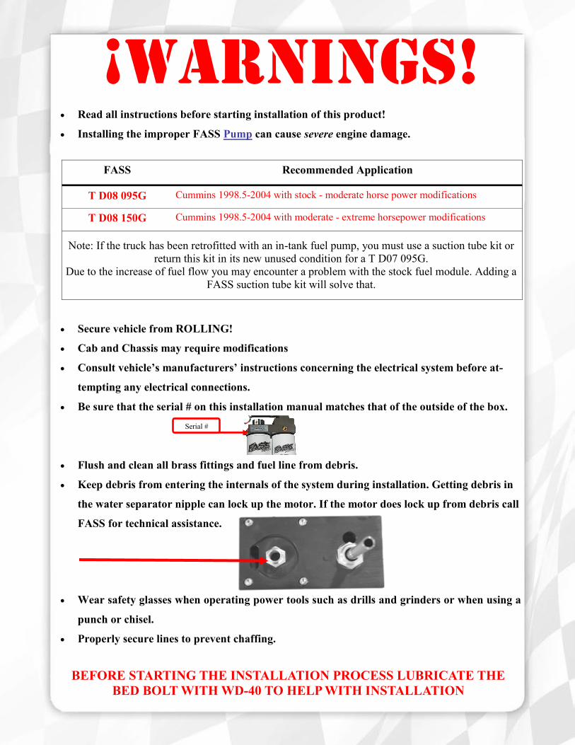
FASS Recommended Application
T D08 095G Cummins 1998.5-2004 with stock - moderate horse power modifications
T D08 150G Cummins 1998.5-2004 with moderate - extreme horsepower modifications
Note: If the truck has been retrofitted with an in-tank fuel pump, you must use a suction tube kit or
return this kit in its new unused condition for a T D07 095G.
Due to the increase of fuel flow you may encounter a problem with the stock fuel module. Adding a
FASS suction tube kit will solve that.
¡WARNINGs! Read all instructions before starting installation of this product!
Installing the improper FASS Pump can cause severe engine damage.
Secure vehicle from ROLLING!
Cab and Chassis may require modifications
Consult vehicle’s manufacturers’ instructions concerning the electrical system before at-
tempting any electrical connections.
Be sure that the serial # on this installation manual matches that of the outside of the box.
Flush and clean all brass fittings and fuel line from debris.
Keep debris from entering the internals of the system during installation. Getting debris in
the water separator nipple can lock up the motor. If the motor does lock up from debris call
FASS for technical assistance.
Wear safety glasses when operating power tools such as drills and grinders or when using a
punch or chisel.
Properly secure lines to prevent chaffing.
BEFORE STARTING THE INSTALLATION PROCESS LUBRICATE THE
BED BOLT WITH WD-40 TO HELP WITH INSTALLATION
INSTALLATION MANUAL
Follow these steps to ensure a simple installation of your new
FASS TITANIUM FUEL SYSTEM
1. Read the installation manual completely before attempting installation. The instal-
lation of this product indicates that the buyer has read and understands the limita-
tions of the FASS manufacturers warranty agreement and accepts the responsibility
of its terms and conditions.
2. Inventory the package components. Notify the place of purchase immediately of
any parts missing or damaged.
3. The installation recommendations contained herein are guidelines. Use good judg-
ment and take into consideration your vehicles' accessories.
4. For best results in accuracy and efficiency (due to training, communication, and our
relationship with our dealer network), we recommend a ViP FASS dealer for the
installation. They are prepared to install the FASS fuel pumps with the most effi-
ciency. If a situation/problem arises during the installation, they are the most pre-
pared for that situation/problem. DPPI is not responsible for any installation mis-
takes.

Titanium Series
Installation
Step 1: Install Electrical Harness
Step 2: Prepare Suction and Return Lines
Step 3: Mount Fuel System
Step 4: Install Fuel Line
Step 5: Check Installation
95 or 150 GPH
16-18 PSI (Approximately)
A fuel pressure gauge is highly recommended to identify fuel filter life and to prevent engine damage!
‘R’
Fuel Return to Tank
“E”
To Engine
Serial Number Location
‘G’
Fuel Pressure
‘T’
Fuel Inlet
Electric Heater
Port
“H”
Coolant Heater
2nd
Electric Heater Port

Contents
FL-1002 x17’
WH-1002
MP-9020
PBR-2001 PFB-2002
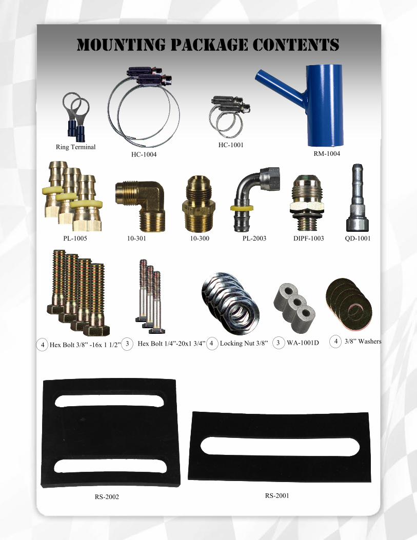
Mounting Package Contents
PL-1005 10-301 10-300 PL-2003 DIPF-1003 QD-1001
RM-1004 HC-1004
HC-1001 Ring Terminal
4 Hex Bolt 3/8” -16x 1 1/2” 3 Hex Bolt 1/4”-20x1 3/4” 4 Locking Nut 3/8” 3 WA-1001D 4 3/8” Washers
RS-2002 RS-2001
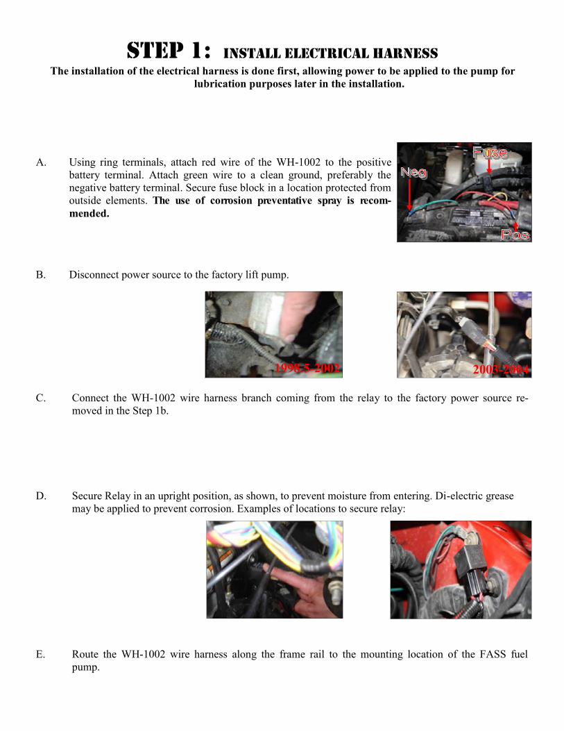
C. Connect the WH-1002 wire harness branch coming from the relay to the factory power source re-
moved in the Step 1b.
B. Disconnect power source to the factory lift pump.
D. Secure Relay in an upright position, as shown, to prevent moisture from entering. Di-electric grease
may be applied to prevent corrosion. Examples of locations to secure relay:
A. Using ring terminals, attach red wire of the WH-1002 to the positive
battery terminal. Attach green wire to a clean ground, preferably the
negative battery terminal. Secure fuse block in a location protected from
outside elements. The use of corrosion preventative spray is recom-
mended.
E. Route the WH-1002 wire harness along the frame rail to the mounting location of the FASS fuel
pump.
Step 1: Install Electrical Harness The installation of the electrical harness is done first, allowing power to be applied to the pump for
lubrication purposes later in the installation.
2003-2004 1998.5-2002
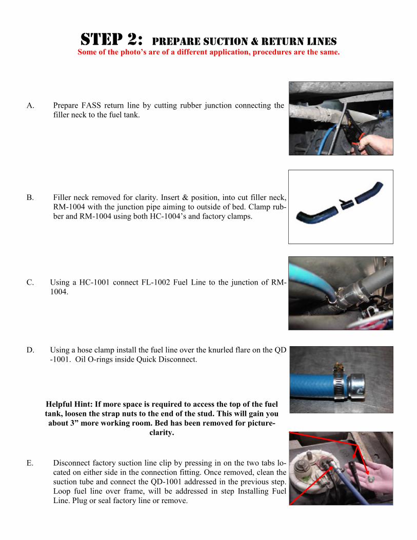
A. Prepare FASS return line by cutting rubber junction connecting the
filler neck to the fuel tank.
C. Using a HC-1001 connect FL-1002 Fuel Line to the junction of RM-
1004.
D. Using a hose clamp install the fuel line over the knurled flare on the QD
-1001. Oil O-rings inside Quick Disconnect.
E. Disconnect factory suction line clip by pressing in on the two tabs lo-
cated on either side in the connection fitting. Once removed, clean the
suction tube and connect the QD-1001 addressed in the previous step.
Loop fuel line over frame, will be addressed in step Installing Fuel
Line. Plug or seal factory line or remove.
B. Filler neck removed for clarity. Insert & position, into cut filler neck,
RM-1004 with the junction pipe aiming to outside of bed. Clamp rub-
ber and RM-1004 using both HC-1004’s and factory clamps.
Step 2: Prepare suction & Return lines
Some of the photo’s are of a different application, procedures are the same.
Helpful Hint: If more space is required to access the top of the fuel
tank, loosen the strap nuts to the end of the stud. This will gain you
about 3” more working room. Bed has been removed for picture-
clarity.
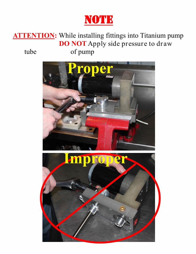
NOTE
ATTENTION: While installing fittings into Titanium pump
DO NOT Apply side pressure to draw
tube of pump
Improper
Proper

Step 3: Mount Fuel System
A. Using thread tape, install the 10-300 into “E” and the 10-302 into the “T” port (on opposite end).
Torque to 40 lb./ft.² Note: Do Not Put Thread Tape on Flare of Fitting ***The use of
thread sealant is not recommended***
B. For fitting purposes. Secure PBR-2001 to pump assembly lightly with (3) 1/4”-20x1 3/4 bolts and (3)
WA-1001D. This will assembly will be used in future steps for correct fitting of brackets. (Note:
Bracket maybe flipped to accommodate your application.)
NOTE: Before installing fittings make sure to inspect for burs or flare imperfections.
When cutting fuel line make sure to blow out line to keep debris from moving forward.

Step 3: Mount Fuel System
F. Connect factory plug into the FASS harness. Connect female plug of the FASS harness into pump.
Turn key to “on”. With pump operating (you may have to bump the starter), turn pump over, liberally
spray WD-40 (or equivalent) into water separator nipple lubricating Gerotor.
E. Position the PBR-2001 to the PFB-2002 pump assembly at the mounting location and check for fit.
Once location is established mark location for mounting in next step.
D. Secure PFB-2002 and RS-2001 with bed bolt in previous step.
C. Unbolt driver side front bed bolt from bed retain bolt for future use. Align RS-2001 with PFB-2002.
.

Step 3: Mount Fuel System
H. Once secure use (3) 1 3/4 bolts and (3) WA-1001D spacers to mount the pump to the bracket.
G. Assemble the FASS pump bracket PBR-2001 using the RS-2002 spacer between PFB-2002 and PBR-
2001 bracket with 4-3/8 bolts, nuts, and washers. Note: Torque bolts not flange nut.

Step 3: Mount Fuel System
I. Apply motor oil to gasket located on filters. Attach to system and
hand tighten.
Fuel Filter –Install FF-3003 on
side of pump with draw tube in
the middle of the filter nipple.
Water Separator Filter –Install FS-
1001 on water separator nipple without
the draw tube. Make sure to insert O-
Ring provided on nipple.
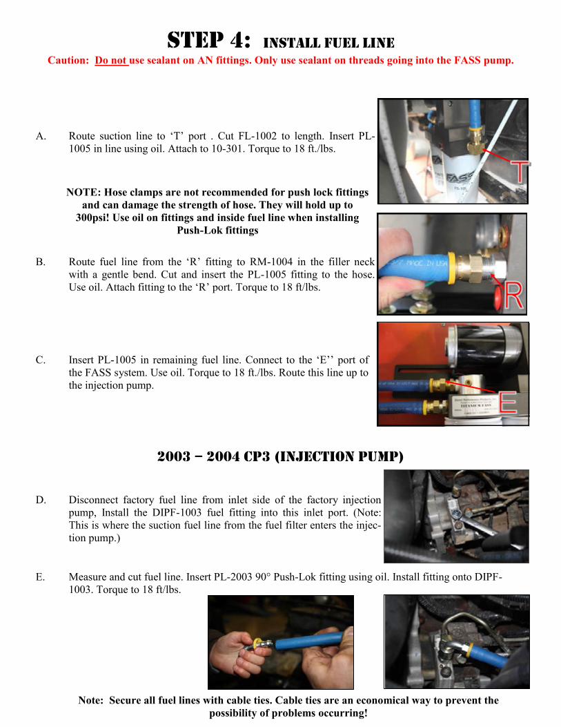
2003 – 2004 CP3 (Injection Pump)
D. Disconnect factory fuel line from inlet side of the factory injection
pump, Install the DIPF-1003 fuel fitting into this inlet port. (Note:
This is where the suction fuel line from the fuel filter enters the injec-
tion pump.)
E. Measure and cut fuel line. Insert PL-2003 90° Push-Lok fitting using oil. Install fitting onto DIPF-
1003. Torque to 18 ft/lbs.
Note: Secure all fuel lines with cable ties. Cable ties are an economical way to prevent the
possibility of problems occurring!
A. Route suction line to ‘T’ port . Cut FL-1002 to length. Insert PL-
1005 in line using oil. Attach to 10-301. Torque to 18 ft./lbs.
B. Route fuel line from the ‘R’ fitting to RM-1004 in the filler neck
with a gentle bend. Cut and insert the PL-1005 fitting to the hose.
Use oil. Attach fitting to the ‘R’ port. Torque to 18 ft/lbs.
C. Insert PL-1005 in remaining fuel line. Connect to the ‘E’’ port of
the FASS system. Use oil. Torque to 18 ft./lbs. Route this line up to
the injection pump.
Step 4: Install Fuel Line
Caution: Do not use sealant on AN fittings. Only use sealant on threads going into the FASS pump.
NOTE: Hose clamps are not recommended for push lock fittings
and can damage the strength of hose. They will hold up to
300psi! Use oil on fittings and inside fuel line when installing
Push-Lok fittings

Step 4: Install Fuel Line
1998.5 – 2002 VP44 (Injection Pump)
D. Disconnect factory fuel line from inlet side of the factory injection
pump, Install the DIPF-1003 fuel fitting into this inlet port. (Note:
This is where the suction fuel line from the fuel filter enters the
injection pump.)
E. Measure and cut fuel line. Insert PL-2003 90° Push-Lok fitting using oil. Install fitting to DIPF-1003.
Torque to 18 ft/lbs.
Note: Secure all fuel lines with cable ties. Cable ties are an economical way to prevent the
possibility of problems occurring!
The factory suction line can be capped off or removed from the truck. Make sure to drain fac-
tory filter. The openings on the filter and tank will need to be capped off to keep debris from
getting into lines or canister.

Hard Starts (DoDge ‘98.5 – ’02)
Answer the following questions:
Did the vehicle start fine without the FASS or HPFP? Do you have high mileage on the VP44? If yes,
have your VP44 checked. Has the VP44 been subjected to a PSI of 5 or less? Has the VP44 been sub-
ject to a failing lift pump? Does it occur more frequently when the conditions are warm? Have you
recently replaced your VP44? Was it used?
If yes to any of these questions, Star t vehicle as soon as you enter the key (do not wait for
the “wait to start” light to go out) If the vehicle starts it suggest that the problem lies with the VP44.
Is the fuel pressure where it should be?
Has the truck had an ECM re-flash? If not, contact your dealer to find the most current flash for your
truck.
Do you have a WH-1002? If yes, refer to the “WH-1002” section located in “Electrical”
Step 5: Review Installation
Blow out any open lines/cover any open ports
Bolts and fasteners properly tightened?
Electrical harness and fuel lines secured and properly tightened? Reconnect the battery.
Has the system been primed?
1. Turn key to the ignition position, turning on the FASS pump for 15 sec..
2. Crank engine and allow to run for at least 1 minute.
Check for leaks.
Start the engine
Recheck all fluid and filter connections for leaks
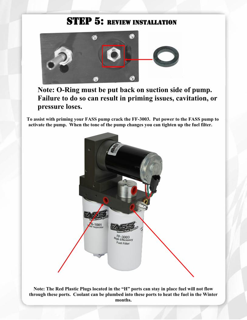
Note: The Red Plastic Plugs located in the “H” ports can stay in place fuel will not flow
through these ports. Coolant can be plumbed into these ports to heat the fuel in the Winter
months.
Note: O-Ring must be put back on suction side of pump.
Failure to do so can result in priming issues, cavitation, or
pressure loses.
To assist with priming your FASS pump crack the FF-3003. Put power to the FASS pump to
activate the pump. When the tone of the pump changes you can tighten up the fuel filter.
Step 5: Review Installation

Filter Cross References
Fuel Filter (Micron Rating) Water Separator (Micron Rating)
Thread Size (1-14) Thread Size (1-14)
Baldwin BF7633 (2M) Baldwin BF 1258 (10M)
Carquest 86528 (2M) Baldwin BF1214
CAT 1P2299 (6M) Baldwin BF7546 (10M)
CAT 1R0750 (2M) Donaldson P558000 (20M)
Donaldson P551025(4M) Donaldson P551000 (10M)
Donaldson P551311 (3M) Donaldson P551001(10M)
Donaldson P551313 (3M) Fleetguard FS1282 (14M)
Donaldson P553203(3M) Fleetguard FS-1000 (10M)
Donaldson P557440 (6M) Fleetguard FS-1001 (10M)
Fleetguard FF5320(2M) Fleetguard FS-1009(14M)
Fram P8334 (2M) Fleetguard FS-1212(14M)
Hastings FF1079 (2M) LuberFiner LFF8011
Wix 33352 (6M) LuberFiner LFF8000
Wix 33528 (2M) Motorcraft FD818 (14M)
Wix 33674 (2M) Wix 33405(14M)
Wix 33522 (10M)
(Currently in use)
Fuel (FWS-3003)
Water (FS-1001)