fantastic pharma airmail issue
TRANSCRIPT

1
INSTALLATION GUIDE
TCP RCKM-02Manual Rack & Pinion, Left-Hand Drive
1964-1970 Mustang/Cougar Small-Block V8 or 6-Cylinder Engines
READ ALL INSTRUCTIONS COMPLETELY AND THOROUGHLY UNDERSTAND THEM BEFORE DOING ANYTHING. CALL TOTAL CONTROL PRODUCTS TECH SUPPORT (916) 388-0288 IF YOU NEED ASSISTANCE.
Description: Manual TCP Rack & Pinion with mounting brackets and hardware ONLY
Applications: Fits ‘64-70 Mustang/Cougar with small-block V8 or 6-cylinder engines

2
1964-66 Mustang
Included in TCP EE-03
Optional use
Optional use
1967-70 Mustang
Included in TCP EE-02
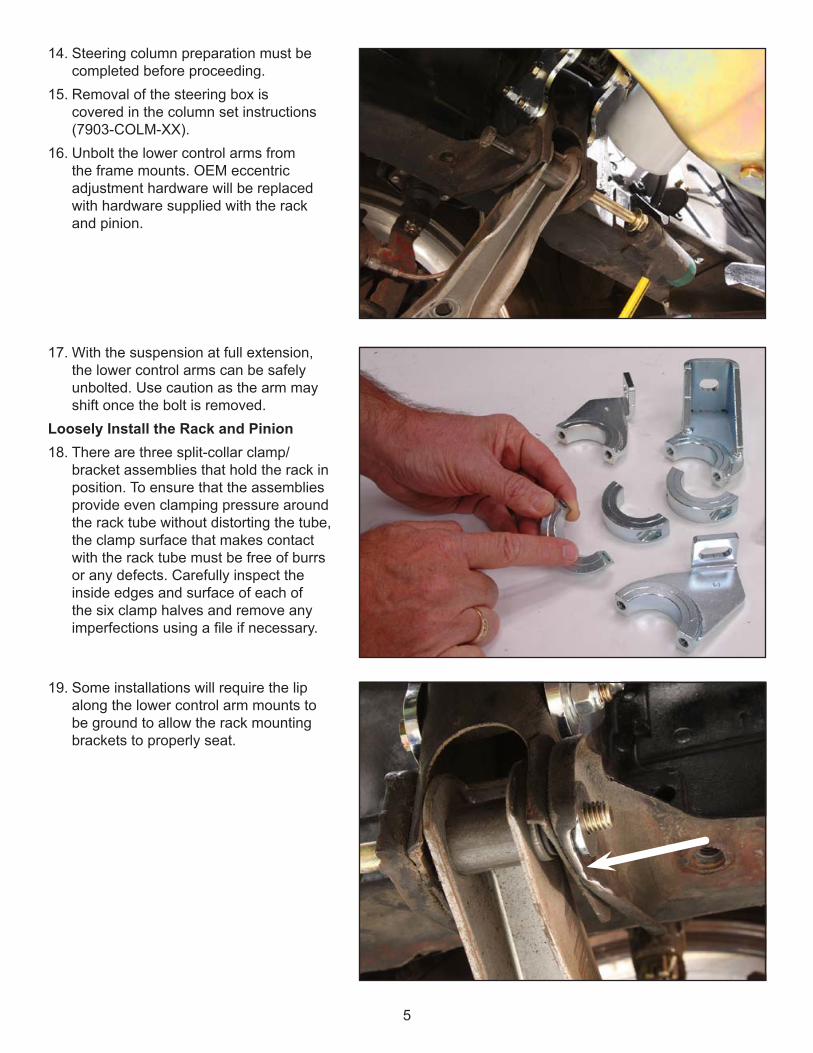
Manual Rack assembly is shown in diagram.
Manual Rack assembly is shown in diagram.

3
PARTS LISTRCKM-02 - Manual Rack and Pinion, SB Mustang Left Hand Drive
Qty Part Number Description1 TCP RCKM-02 Manual rack and pinion, left-hand drive, small-block Mustang/Cougar1 7900-185 Small-block mounting bracket set
7900-185 - Mounting Bracket Set, Small BlockQty Part Number Description3 7900-100 Clamp collar drilled half1 7900-113 Frame bracket, passenger side, small block1 7900-115 Lower-arm bracket, passenger side (bent left), small block1 7900-117 Lower-arm bracket, driver side (bent right), small block1 7918-005 Hardware bag
7918-005 - Hardware BagQty Part Number Description2 3100-050-C1.50Y Bolt, 1/2-13 x 1-1/2” hex head Grade 82 3100-050-C4.50Y Bolt, 1/2-13 x 4-1/2” hex head Grade 82 3101-050-13C Locknut, 1/2-13 nylon insert6 3103-031F1.00C Socket head, 5/16-24 x 1” cap screw6 3108-031H-S High-collar lockwasher, 5/16”, stainless steel2 3108-050L-C Lockwasher 1/2” regular6 3120-050S-Y Washer, 1/2” hardened flat SAE2 7900-022 Frame spacer, 1.175 x 1.875 x .25 thick, slotted2 7900-203 Frame spacer, 1.175 x 1.875 x .125 thick, slotted
TCP TIER-XX - Inner Tie-Rod Adapter Set (1 of the 3 listed)Qty Part Number Description1 TCP TIER-01 Rack tie-rod adapters, .46” minor diameter, fits Comet 60-65, Cyclone 64-65,
Falcon 60-65, Mustang 64-66, and Ranchero 60-651 TCP TIER-02 Rack tie-rod adapters, .49” minor diameter, fits Cougar 67-69 (exc.
Eliminator), and Mustang 67-69 (exc. Boss)1 TCP TIER-03 Rack tie-rod adapters, .53” minor diameter, fits Cougar Eliminator 67-69,
Cougar 1970, Mustang Boss 69, and Mustang 1970
INSTRUCTIONSNOTE: A 1965 Mustang was used for the following images and may show slight differences from the later Mustang and Cougar platforms. The installation procedure is identical unless noted.Removal of Factory Components All OEM steering components will be removed before starting to install the rack and pinion.

4
1. Remove the battery cable from the negative side of the battery.
2. Raise the vehicle using a two-post lift or jack and secure with jack stands so that the suspension hangs freely and the vehicle is safe to work underneath.
3. Unbolt the factory tubular crossmember that runs underneath the oil pan. There is one bolt at each frame rail. This crossmember is replaced by the rack and pinion and will not be reused.
OEM power steering cars only4. Disconnect the two power steering lines
at the control valve. 5. Fluid will be present, so be prepared to
plug the lines or drain remaining fluid from the system.
6. Unbolt the power ram bracket from the frame.
7. Loosen the fastening bolts to the power steering pump, swing the pump down, and remove the fan belt.
8. Unbolt all power steering pump brackets and remove the pump, brackets, and hoses as an assembly.
9. Remove the tie rods using a balljoint separator or similar tool.
10. If replacing the inner and outer tie rods, remove the outer tie rod from the spindle. The tie rods and center link will be removed as an assembly.
11. If reusing the inner and outer tie rods, remove the inner tie rods from the center link only.
12. Separate the center link from the pitman arm using a balljoint separator or similar tool.
13. Unbolt the idler arm from the vehicle and remove the steering system assembly.
5
14. Steering column preparation must be completed before proceeding.
15. Removal of the steering box is covered in the column set instructions (7903-COLM-XX).
16. Unbolt the lower control arms from the frame mounts. OEM eccentric adjustment hardware will be replaced with hardware supplied with the rack and pinion.
17. With the suspension at full extension, the lower control arms can be safely unbolted. Use caution as the arm may shift once the bolt is removed.
Loosely Install the Rack and Pinion18. There are three split-collar clamp/
bracket assemblies that hold the rack in position. To ensure that the assemblies provide even clamping pressure around the rack tube without distorting the tube, the clamp surface that makes contact with the rack tube must be free of burrs or any defects. Carefully inspect the inside edges and surface of each of the six clamp halves and remove any imperfections using a file if necessary.
19. Some installations will require the lip along the lower control arm mounts to be ground to allow the rack mounting brackets to properly seat.

6
23. Using a 5/16-24 tap, chase the threads of the split collar brackets.
24. Using a 1/2-13 tap, chase the threads of the factory-crossmember mounting holes.
20. Bolt the lower rack brackets to the lower control arm mounts using the orientation and hardware shown on page two. The bracket’s bend will face inward or outward depending upon the year of the vehicle.
21. Refer to installation guide (7903-EE-02), packaged with eccentric eliminator plates (TCP EE-02), for specific instructions regarding orientation of plates.
22. The bolts should be snug enough to remove slack, but loose enough to allow the brackets to pivot and slide vertically by hand.

7
25. On the passenger-side frame rail, loosely bolt the frame bracket to the OEM-crossmember mounting point using the 1/2-13 x 1-1/2” bolt, flat washer, and lockwasher.
26. Raise the rack-and-pinion assembly into position along the loosely installed brackets.
27. On driver-side frame rail, loosely bolt the rack and pinion’s attached frame bracket to the OEM-crossmember mounting point, using the same hardware as the passenger side bracket.

8
28. Loosely install each of the clamp collars (Item 2) onto their respective brackets so that the clamps seat against the rack tube to prevent rocking, but still allow rotation and sliding movement. A light lubricant can be used to more easily permit sliding of the brackets.
29. The opposing gaps between each clamp half must be even to prevent distorting the rack tube when tightened.
Mounting Bracket Alignment30. IMPORTANT: If any of the mounting
brackets do not easily align with the vehicle mounting points do not use the hardware to draw the rack and brackets into place. Doing so will bend the rack tube and create a binding condition that hinders performance and could potentially damage the rack. Each of the mounting brackets is slotted and additional optional-use spacers are included to accommodate differences in chassis dimensions.
31. If the outer brackets do not seat against the frame rails, use the 1/8”- and/or 1/4”-thick spacers to take up any slack. Some installations may require uneven spacer stacks to correctly align the rack brackets. Each vehicle is different and will need to be shimmed accordingly.
32. The inner brackets at the lower control arm mounts should seat against a 1/4” thick spacer (‘64-66) or 1/4” eccentric eliminator plate (‘67-70) with the frame brackets seated squarely against the frame rails.
33. In rare instances it may be necessary to increase the slot length of the brackets to achieve a proper fit. For safety purposes the brackets are made from mild steel and can be modified with fairly common tools.
9
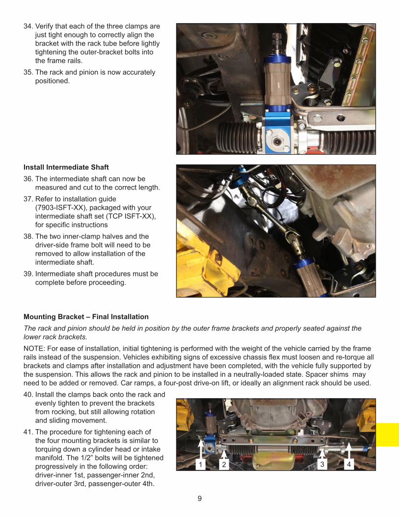
34. Verify that each of the three clamps are just tight enough to correctly align the bracket with the rack tube before lightly tightening the outer-bracket bolts into the frame rails.
35. The rack and pinion is now accurately positioned.
Install Intermediate Shaft36. The intermediate shaft can now be
measured and cut to the correct length.37. Refer to installation guide
(7903-ISFT-XX), packaged with your intermediate shaft set (TCP ISFT-XX), for specific instructions
38. The two inner-clamp halves and the driver-side frame bolt will need to be removed to allow installation of the intermediate shaft.
39. Intermediate shaft procedures must be complete before proceeding.
Mounting Bracket – Final InstallationThe rack and pinion should be held in position by the outer frame brackets and properly seated against the lower rack brackets.NOTE: For ease of installation, initial tightening is performed with the weight of the vehicle carried by the frame rails instead of the suspension. Vehicles exhibiting signs of excessive chassis flex must loosen and re-torque all brackets and clamps after installation and adjustment have been completed, with the vehicle fully supported by the suspension. This allows the rack and pinion to be installed in a neutrally-loaded state. Spacer shims may need to be added or removed. Car ramps, a four-post drive-on lift, or ideally an alignment rack should be used.40. Install the clamps back onto the rack and
evenly tighten to prevent the brackets from rocking, but still allowing rotation and sliding movement.
41. The procedure for tightening each of the four mounting brackets is similar to torquing down a cylinder head or intake manifold. The 1/2” bolts will be tightened progressively in the following order: driver-inner 1st, passenger-inner 2nd, driver-outer 3rd, passenger-outer 4th.
1 2 3 4

10
42. Begin by snugging up each bolt to remove any free play.43. Verify that each bracket will seat squarely against its mounting surface without drawing the rack tube.44. Make two to three passes through the tightening order to bring each bolt to its specified torque value.
Inner brackets – 60 lb-ft.; Outer brackets – 75 lb-ft.Check for BindingAt each step of final tightening, the rack must be checked for binding or tightness throughout its range of travel. A slight bend in the rack tube or the tube being pinched into a slight oval will create additional friction against the rack’s internal guide bushing or piston (power rack). Binding symptoms, probable causes, and solutions are explained in the following steps.45. Using an even motion, turn the steering wheel from lock-to-lock. The amount of resistance should feel even
from one end of the travel range to the other. Any noticeable increase or decrease in tension indicates a possible issue. • Notchy feeling or bump every 1/8th turn – The
pinion set screw adjustment at the base of the pinion housing is too tight. Loosen the large lock nut (15/16” hex) surrounding the set screw (5/16” allen) at the bottom of the pinion housing. While lightly rocking the steering wheel back and forth, tighten the set screw until it is seated then loosen 1/4 turn. Hold the set screw in position with an allen wrench and tighten the lock nut. The steering should feel smooth and have zero to 1/8” of play at the steering wheel. Too loose of an adjustment allows excessive play at the steering wheel. Too tight of an adjustment makes steering overly sensitive and can prevent the system from returning to center while driving.
• Notchy feeling or bump every ½ or ¼ turn – This usually indicates a binding condition at the intermediate steering shaft u-joints. Verify that the steering shafts do not extend into the open area of u-joint, causing it to bind.
• Gradual increase in resistance - The rack tube may be slightly bent due to bracket misalignment. This must be corrected before proceeding.
• Light variations in tension – This is very common and will smooth out once the internal guide bushings have developed wear patterns (approx. 1,000 miles); similar to piston rings seating within a cylinder.
46. Continue by tightening the passenger-side outer clamp to 13-15 lb-ft., and check for binding.• Tightness near full-left lock (manual rack) or center of travel (power rack) indicates that the
passenger-side clamp has created one of the following issues.• The clamp is too tight and needs to be loosened slightly.• The clamp is not square to the bracket-side clamp. Check by measuring the gap at the opposite ends
of the clamp.• There is debris, a burr, or other imperfection on the clamp or rack tube that must be removed.• Recheck for binding.

11
47. Tighten the two inner clamps to 13-15 lb-ft., and check for binding.• Tightness near full-left lock (manual rack) or center of travel (power rack) indicates that the
passenger-side clamp has created one of the following issues.• The clamp is too tight and needs to be loosened slightly.• The clamp is not square to the bracket-side clamp. Check by measuring the gap at the opposite ends
of the clamp.• There is debris, a burr, or other imperfection on the clamp or rack tube that must be removed.• Recheck for binding.
Tie-Rod Installation48. Verify that the rack has full travel.49. Turn the steering wheel to full left lock.50. From one of the frame rails, measure the
distance that the center link travels from full left to full right lock. The rack should travel 6-3/8”.
51. If travel is less than 6-3/8”, look for binding at the u-joints or with exhaust headers that may be limiting travel.
Centering the Rack and Pinion52. From full right lock, move the center link
3-3/16” toward the left. This is the rack and pinion’s center of travel.
53. Tie-rod assemblies can now be installed as described in their respective installation guides (7903-TIER-XX).
54. Installation of inner tie rod requires use of vehicle specific tie-rod adapter packaged with rack and pinion.55. Adjusting the tie-rods to correctly set the alignment toe must be done with the suspension fully weighted
and the rack and pinion at its center of travel.56. Recheck all hardware for each portion of the steering system (aftermarket and OEM) to ensure it has been
tightened to the proper torque specification.The installation for the complete subframe connector package is complete.

12
Total Control ProductsA Chris Alston’s Chassisworks, Inc. Brand8661 Younger Creek DriveSacramento, CA 95828Phone: 916-388-0288Technical Support: [email protected]
7903-RCKM-02 REV 02/24/11
WARRANTY NOTICE:There are NO WARRANTIES, either expressed or implied. Neither the seller nor manufacturer will be liable for any loss, damage or injury, direct or indirect, arising from the use or inability to determine the appropriate use of any products. Before any attempt at installation, all drawings and/or instruction sheets should be completely reviewed to determine the suitability of the product for its intended use. In this connection, the user assumes all responsibility and risk. We reserve the right to change specification without notice. Further, Chris Alston’s Chassisworks, Inc., makes NO GUARANTEE in reference to any specific class legality of any component. ALL PRODUCTS ARE INTENDED FOR RACING AND OFF-ROAD USE AND MAY NOT BE LEGALLY USED ON THE HIGHWAY. The products offered for sale are true race-car components and, in all cases, require some fabrication skill. NO PRODUCT OR SERVICE IS DESIGNED OR INTENDED TO PREVENT INJURY OR DEATH.