fan coil units model deco - biddle · 2 free-hanging stylish model the free-standing business model...
TRANSCRIPT

DECO
.NE-
uk.2
014-
11.P
DF•1
4102
842-
1
Individual climate control
Fan coil unitsModel DECO

2
Free-hanging Stylish model
The free-standing Business model fits in very well with the interior.
Benefits model DECO
• High quality climate • Low sound level• Individual control • Various controls• Wide scope of application• Directional heating and cooling • Many models and colours• Easy installation and maintenance
Fan coil unitsComfortable indoor climate
In buildings a pleasant work and living environment are, to a large degree, determined by the quality of the indoor climate. A comfortable climate in a room will be noticed by staff and visitors. The Biddle DECO fan coil unit gives you optimum control of the indoor climate by heating, cooling and/or ventilating the room.
High quality climate
The DECO proves that a comfortable living climate at a low noise level can be achieved. The unit is positioned in the room in such a way that the discharged air stream is distributed evenly across the room without causing a nuisance to the people in it.
Individual control
People like to have control of the climate in their working environments. Everyone has their own preference for air temperature and quality. Biddle fan coil units anticipate the need to control the climate per room. Users may simply regulate the room temperature and the fresh air supply themselves.
Wide scope of application
The Biddle DECO fan coil units are suitable for use in refurbished or newly built offices, meeting rooms, hotels, schools, care centres, hospitals, server rooms and retail outlets. The DECO is available in a variety of styles and designs, making it suitable for a wide range of applications.

3
Adjustable outlet grilleThe air is discharged “directionally”, max.: 20° sideward, 10° backward and 30° forward.
The filter can be withdrawn from the front of the unit.
Optional accessories: various controls
The DECO can incorporate an airside controller or a combined air- and waterside controller, either option having the corresponding easy-to-use control panel. The controller provides for efficient heating and cooling at the lowest possible noise level. The controller comes with a weekly timer and a room thermostat as a standard and can also be combined with a CO2-sensor to control the volume of fresh air (see page 7).
Comfort where you need it
The Biddle fan coil unit features an innovative adjustable discharge grille (Multi Vector Technology), which is made up of a number of stacked sheets with a hole pattern. Using this discharge grille, the direction of the air can be regulated. To cool a room, the air is blown into the room differently than when heating it. The grille enables the user to direct the air to or from the place where he or she is working, thus providing “comfort where you need it”.
Easy to install and maintain
All fan coil units that have an airside or combined controller are delivered ready to use, so they are fast and easy to install. All models come standard with a removable G2 filter. This filter prevents dust in the inlet air from settling on the battery or fans. The filter is hidden from view using a filter frame, which is easy to remove. The filter is fast and easy to clean with a vacuum cleaner.

4
Recessed floor model
A wide range of models
People prefer climate control equipment that is unobtrusive and fits in with its surroundings. That’s why Biddle has devoted so much attention to the design of the DECO fan coil unit and has made it suitable for a wide range interior designs.
Model with casing
This model is available either as a wall model (F) or as a ceiling model (C) and can be freely standing or suspended. The next units are available:
1. Stylish model (S): with curved plastic side covers2. Business model (B): with straight metal side covers
Recessed model
The recessed model (R) is easy to integrate into the wall (F) or ceiling void (C).
Standard colour combinations
Fan coil units with casing are available in two colours. Next to the conventional white colour, the unit is available in the colour titanium. Unless the customer requests a specific colour, the unit comes standard in white. Other colours are of course available at an extra charge.
Ceiling model (Business)
White (Business)
Titanium (Business)
Casing Filter frame
Stylish (S) RAL 9016 = white RAL 9006 = white aluminium Business (B) Polydrox 73830 = titanium Polydrox 73830 = titanium RAL 9016 = white RAL 9006 = wit aluminium

5
TypecodeDECO 75-H1C3-R-FS12
Unit size 50 = 140 - 605 m3/h 75 = 180 - 860 m3/h100 = 275 - 1180 m3/h 125 = 300 - 1400 m3/h 150 = 390 - 1800 m3/h
Coil typeH1, H2, H4 = Water heatingC2, C3, C4 = Water coolingH1C3 = Water heating and - cooling HE = electric heating(1,2,3,4 = number of rows)
Water connectionsR = right L = leftHE = electrical connection on the left side.
Model typeFS = floor model: stylishFB = floor model: businessCS = ceiling model: stylishCB = ceiling model: businessFR = recessed Floor modelCR = recessed ceiling model2 - 12 = see figure 1: model types
Figuur 1: model types
Many optionsBasic models
The fan coil unit is available in 5 unit sizes: DECO 50, DECO 75, DECO 100, DECO 125 and DECO 150. The air flow rates of these types range from 140 - 1800 m³/h. Model DECO can heat, cool or ventilate the room. The unit is available in different models (see figure 1).
Recirculation Ventilation Recirculation/Ventilation
Free-standing
Floor model(FS or FB)
Free-hanging
Ceiling model(CS or CB)
Recessed
Floor model(FR)
Recessed
Ceiling model(CR)
CS2CB2
CS6CB6
CS 8CB8
CS10CB10
CS12CB12
CR2 CR4 CR6 CR8 CR10 CR12
* All models are available as top discharge types. Only the recessed model has the possibility of a discharge plenum for front discharge. = inspection side = air direction
FB4FS2FB2
FS6FB6
FS8FB8
FS10FB10
FS12FB12
FR4FR2 FR6 FR8 FR10 FR12
Floor model (Stylish)

6
Standard delivery
Units with casing come with:• adjustable discharge grille • removable air filter• integrated condensate draining pump (only in ceiling model with cooling mode)• integrated frost-protection device and damper control (only in ventilation model)• condensate tray (only in models with cooling mode)
Recessed units come with:• removable air filter • frost-protection device (only in ventilation model)• condensate tray (only in models with cooling mode)
Accessories
The following control accessories are available (see page 7):• air side controller • air- and waterside controller • control panel • CO2 sensor• low-voltage cables (different lengths)• ventilation module for coupling to an exhaust fan
Also the following accessories are available (see page 23 - 27):• sound - damping air inlet section• wall sleeve• wall grate • roof cap• discharge plenum for recessed models• flexible connection sleeves with or without duct connecting flange • adjustable discharge grille• wall and ceiling grilles • condensate draining pump (standard in encased ceiling model with cooling mode, optional in floor model)
Biddle and customer may agree on custom alterations or modifications to the unit.
Weights of various models
The weights of the various fan coil models are represented below (in kg).
Model Type DECO 50 DECO 75 DECO 100 DECO 125 DECO 150
With casing recirculation 39 52 62 75 84 - stylish ventilation 41 55 65 79 88 (type FS and CS) recirculation/ventilation 41 55 65 79 88
With casing recirculation 43 56 66 79 89 - business ventilation 45 59 69 83 92 (type FB and CB) recirculation/ventilation 45 59 69 83 92
Recessed recirculation 29 40 47 57 64 (type FR and CR) ventilation 31 42 50 61 68 recirculation/ventilation 31 42 50 61 68
Adjustable discharge grille
Wall grille
CO2 sensor

7
Plug & play
Waterside connection (H1C3)
Control options
Model DECO is available with three types of control, in order to make it suitable for every project.
1. Basic (without control): The fan coil unit (only the recirculation model) is provided with a transformer and is wired in a fixed speed.
2. Airside controlThis plug & play controller regulates the fan speed (3 speeds) to achieve the desired room temperature.
3. Combined air- and waterside controllerThis plug & play controller regulates both the fan speed and the discharge air temperature to achieve the desired room temperature. The ventilation unit is delivered with the combined controller.
Controller with LCD display
The control panel has various soft-touch keys and a clear LCD display. The desired room temperature can be set using the control panel, after which you can choose to have the controller regulate the climate either automatically or using one of the three fan speeds. Next to this functionality, the control panel features an integrated weekly timer, which can be used to switch the unit automatically on and off each day of the week. The keys of the control panel can be blocked using a key lock to prevent unwanted use.
One single control panel allows the user to interconnect and operate a maximum of ten units. The maximum length of the control cables within a control system is 100 metres. The control panel offers menus for different purposes, including operation, installation and service menus as well as a menu for setting the weekly timer.
• Automatic or manual operationThe control panel allows the user to select either automatic or manual operation of the DECO.
• Weekly timerThe DECO comes standard with a weekly timer, which allows the user to automatically switch the unit on and off per day of the week.
• CO2 sensorThe ventilation units can be equipped with a sensor to read the CO2 level in the room. The sensor ensures that the CO2 value preset in the control panel is maintained by automatically increasing or reducing the supply of fresh air.
• Integrated frost protection and air valve controlThe ventilation units have a controller-integrated frost protection thermostat and air valve control. The frost protection reduces the risk of the battery freezing (preset at 5°C). In the event of a power interruption or failure, the air valve automatically switches to the recirculation mode.
• Ready to use Units with an airside or combined controller are delivered ready to use. The power cable (1.5 m), which has a moulded-on, earthed plug, is connected to the terminal box in the side of the unit. Via the connector plate and the interfaces in the terminal box, components such as slave units, control panel and in- and outputs can be connected to the PCB.
The control panel is inclusive room thermostat.

8
Technical data DECO 50
Installation dataelectric supply V ; ph ; Hz 230 ; 1 ; 50 max. running current A 0.35max. consumed power W 90
General selection data speed 1 2 3 4 5 6tapping voltage V 70 90 115 130 170 230power consumption, fans A 0.14 0.19 0.24 0.26 0.29 0.34input power, fans W 10 20 30 35 50 75air displacement m³/h 140 205 315 350 450 605sound level dB(A) 15 24 33 38 45 51
Heating H1 LPHW 82/71°C H2 LPHW 82/71°C H4 LPHW 60/40°Cspeed 1 2 3 4 5 6 1 2 3 4 5 6 1 2 3 4 5 6
air displacement m³/h 140 205 315 350 450 605 140 205 315 350 450 605 140 205 315 350 450 605air inlet temp. ºC -10 -10 -10heating capacity kW 3 4 5.5 5.9 6.9 8.4 4.1 5.6 8 8.8 10.6 13.3 3 4.3 6.4 7.1 8.8 11.4discharge temp. ºC 47 42 36 35 31 27 67 63 58 57 53 49 48 46 44 44 42 40
water flow rate l/h 0.07 0.09 0.12 0.13 0.15 0.19 0.09 0.13 0.18 0.19 0.24 0.30 0.04 0.05 0.08 0.09 0.11 0.14water pressure drop kPa 10.5 17.5 30.7 35.1 46.2 65.3 5.4 9.5 17.8 20.7 29.2 43.2 0.4 0.7 1.3 1.6 2.3 3.7air inlet temp. ºC 0 0 0heating capacity kW 2.6 3.4 4.7 5.1 6 7.3 3.5 4.8 6.9 7.5 9.1 11.4 2.4 3.4 5.1 5.6 7 9discharge temp. ºC 50 46 41 40 37 33 69 65 61 59 56 52 48 46 45 44 43 41water flow rate l/h 0.06 0.08 0.11 0.11 0.13 0.16 0.08 0.11 0.15 0.17 0.20 0.25 0.03 0.04 0.06 0.07 0.08 0.11water pressure loss kPa 8 13.4 23.6 27 35.6 50.4 4.1 7.2 13.6 15.8 22.3 33 0.2 0.4 0.9 1.1 1.6 2.4air inlet temp. ºC 10 10 10heating capacity kW 2.2 2.9 4 4.3 5 6.2 2.9 4.1 5.8 6.3 7.7 9.6 1.8 2.6 3.9 4.2 5.3 6.8discharge temp. ºC 54 50 46 45 42 39 70 67 63 62 59 56 47 47 45 45 44 42water flow rate l/h 0.05 0.06 0.09 0.10 0.11 0.14 0.07 0.09 0.13 0.14 0.17 0.21 0.02 0.03 0.05 0.05 0.06 0.08water pressure drop kPa 6 10 17.6 20.1 26.6 37.7 3 5.3 10 11.7 16.5 24.5 0.1 0.3 0.5 0.6 1 1.5air inlet temp. ºC 20 20 20heating capacity kW 1.8 2.4 3.3 3.6 4.2 5.1 2.4 3.3 4.8 5.2 6.3 7.9 1.3 1.8 2.7 3 3.7 4.7discharge temp. ºC 58 54 51 50 47 45 71 68 65 64 62 59 47 46 45 45 44 43water flow rate l/h 0.04 0.05 0.07 0.08 0.09 0.11 0.05 0.07 0.11 0.12 0.14 0.18 0.02 0.02 0.03 0.04 0.04 0.06water pressure drop kPa 4.2 7.1 12.5 14.3 19 27 2.1 3.8 7.1 8.3 11.7 17.4 0.1 0.1 0.3 0.3 0.5 0.8
Cooling C2 LPCW 6/12°C C3 LPCW 6/12°C C4 LPCW 6/12°Cspeed 1 2 3 4 5 6 1 2 3 4 5 6 1 2 3 4 5 6
air displacement m³/h 140 205 315 350 450 605 140 205 315 350 450 605 140 205 315 350 450 605air inlet temp. ºC 23 23 23relative humidity % 50 50 50cooling capacity total kW 0.5 0.7 1 1.1 1.3 1.6 0.6 0.8 1.1 1.3 1.6 2 0.6 0.9 1.2 1.3 1.6 2.2sensible capacity kW 0.5 0.7 1 1.1 1.3 1.6 0.5 0.8 1.1 1.3 1.6 2 0.6 0.8 1.2 1.3 1.6 2.2discharge temp. ºC 12 13 15 14 14 15 11 12 13 12 13 13 11 11 12 12 12 12water flow rate l/s 0.02 0.03 0.04 0.04 0.05 0.06 0.02 0.03 0.04 0.05 0.06 0.08 0.03 0.04 0.05 0.05 0.06 0.09water pressure drop kPa 0.5 1 1.7 2 2.8 4.1 0.3 0.6 1 1.3 1.9 2.8 0.2 0.4 0.8 0.9 1.2 2.1
* The control system limits the air discharge temperature to 50°C. This limitation is not included in the selection data.** Water pressure loss, exclusive three- or two- way valve. For sft-values of three- or two-way valve, see page 22.
9
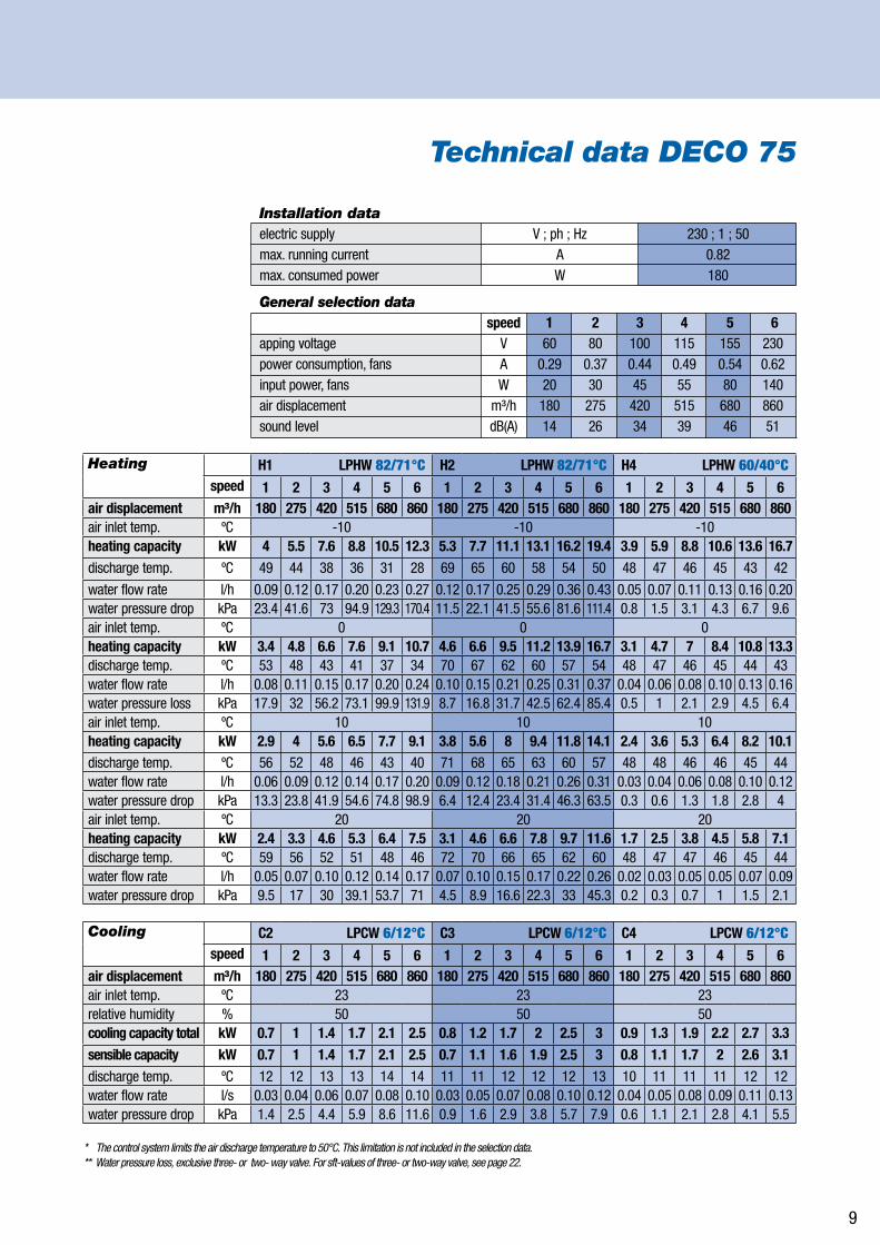
Technical data DECO 75
Installation dataelectric supply V ; ph ; Hz 230 ; 1 ; 50 max. running current A 0.82max. consumed power W 180
General selection data speed 1 2 3 4 5 6apping voltage V 60 80 100 115 155 230power consumption, fans A 0.29 0.37 0.44 0.49 0.54 0.62input power, fans W 20 30 45 55 80 140 air displacement m³/h 180 275 420 515 680 860sound level dB(A) 14 26 34 39 46 51
Heating H1 LPHW 82/71°C H2 LPHW 82/71°C H4 LPHW 60/40°Cspeed 1 2 3 4 5 6 1 2 3 4 5 6 1 2 3 4 5 6
air displacement m³/h 180 275 420 515 680 860 180 275 420 515 680 860 180 275 420 515 680 860air inlet temp. ºC -10 -10 -10heating capacity kW 4 5.5 7.6 8.8 10.5 12.3 5.3 7.7 11.1 13.1 16.2 19.4 3.9 5.9 8.8 10.6 13.6 16.7discharge temp. ºC 49 44 38 36 31 28 69 65 60 58 54 50 48 47 46 45 43 42
water flow rate l/h 0.09 0.12 0.17 0.20 0.23 0.27 0.12 0.17 0.25 0.29 0.36 0.43 0.05 0.07 0.11 0.13 0.16 0.20water pressure drop kPa 23.4 41.6 73 94.9 129.3 170.4 11.5 22.1 41.5 55.6 81.6 111.4 0.8 1.5 3.1 4.3 6.7 9.6air inlet temp. ºC 0 0 0heating capacity kW 3.4 4.8 6.6 7.6 9.1 10.7 4.6 6.6 9.5 11.2 13.9 16.7 3.1 4.7 7 8.4 10.8 13.3discharge temp. ºC 53 48 43 41 37 34 70 67 62 60 57 54 48 47 46 45 44 43water flow rate l/h 0.08 0.11 0.15 0.17 0.20 0.24 0.10 0.15 0.21 0.25 0.31 0.37 0.04 0.06 0.08 0.10 0.13 0.16water pressure loss kPa 17.9 32 56.2 73.1 99.9 131.9 8.7 16.8 31.7 42.5 62.4 85.4 0.5 1 2.1 2.9 4.5 6.4air inlet temp. ºC 10 10 10heating capacity kW 2.9 4 5.6 6.5 7.7 9.1 3.8 5.6 8 9.4 11.8 14.1 2.4 3.6 5.3 6.4 8.2 10.1discharge temp. ºC 56 52 48 46 43 40 71 68 65 63 60 57 48 48 46 46 45 44water flow rate l/h 0.06 0.09 0.12 0.14 0.17 0.20 0.09 0.12 0.18 0.21 0.26 0.31 0.03 0.04 0.06 0.08 0.10 0.12water pressure drop kPa 13.3 23.8 41.9 54.6 74.8 98.9 6.4 12.4 23.4 31.4 46.3 63.5 0.3 0.6 1.3 1.8 2.8 4air inlet temp. ºC 20 20 20heating capacity kW 2.4 3.3 4.6 5.3 6.4 7.5 3.1 4.6 6.6 7.8 9.7 11.6 1.7 2.5 3.8 4.5 5.8 7.1discharge temp. ºC 59 56 52 51 48 46 72 70 66 65 62 60 48 47 47 46 45 44water flow rate l/h 0.05 0.07 0.10 0.12 0.14 0.17 0.07 0.10 0.15 0.17 0.22 0.26 0.02 0.03 0.05 0.05 0.07 0.09water pressure drop kPa 9.5 17 30 39.1 53.7 71 4.5 8.9 16.6 22.3 33 45.3 0.2 0.3 0.7 1 1.5 2.1
Cooling C2 LPCW 6/12°C C3 LPCW 6/12°C C4 LPCW 6/12°Cspeed 1 2 3 4 5 6 1 2 3 4 5 6 1 2 3 4 5 6
air displacement m³/h 180 275 420 515 680 860 180 275 420 515 680 860 180 275 420 515 680 860air inlet temp. ºC 23 23 23relative humidity % 50 50 50cooling capacity total kW 0.7 1 1.4 1.7 2.1 2.5 0.8 1.2 1.7 2 2.5 3 0.9 1.3 1.9 2.2 2.7 3.3sensible capacity kW 0.7 1 1.4 1.7 2.1 2.5 0.7 1.1 1.6 1.9 2.5 3 0.8 1.1 1.7 2 2.6 3.1discharge temp. ºC 12 12 13 13 14 14 11 11 12 12 12 13 10 11 11 11 12 12water flow rate l/s 0.03 0.04 0.06 0.07 0.08 0.10 0.03 0.05 0.07 0.08 0.10 0.12 0.04 0.05 0.08 0.09 0.11 0.13water pressure drop kPa 1.4 2.5 4.4 5.9 8.6 11.6 0.9 1.6 2.9 3.8 5.7 7.9 0.6 1.1 2.1 2.8 4.1 5.5
* The control system limits the air discharge temperature to 50°C. This limitation is not included in the selection data.** Water pressure loss, exclusive three- or two- way valve. For sft-values of three- or two-way valve, see page 22.

10
Technical data DECO 100
Installation dataelectric supply V ; ph ; Hz 230 ; 1 ; 50 max. running current A 0.82max. consumed power W 180
General selection data speed 1 2 3 4 5 6tapping voltage V 70 90 115 130 170 230power consumption, fans A 0.33 0.41 0.51 0.56 0.63 0.69input power, fans W 25 40 60 70 105 155air displacement m³/h 275 405 635 700 900 1180sound level dB(A) 15 24 34 38 46 51
Heating H1 LPHW 82/71°C H2 LPHW 82/71°C H4 LPHW 60/40°Cspeed 1 2 3 4 5 6 1 2 3 4 5 6 1 2 3 4 5 6
air displacement m³/h 275 405 635 700 900 1180 275 405 635 700 900 1180 275 405 635 700 900 1180air inlet temp. ºC -10 -10 -10heating capacity kW 5.9 7.9 11 11.8 13.8 16.5 8 11.1 16.2 17.5 21.3 26.1 5.9 8.5 12.9 14.1 17.6 22.2discharge temp. ºC 47 42 36 35 31 27 68 63 58 57 53 49 48 46 44 44 42 40
water flow rate l/h 0.13 0.18 0.25 0.26 0.31 0.37 0.18 0.25 0.36 0.39 0.47 0.58 0.07 0.10 0.16 0.17 0.21 0.27water pressure drop kPa 8.2 13.8 24.9 28.2 37.1 51 4.2 7.5 14.5 16.6 23.5 33.6 0.3 0.5 1.1 1.3 1.9 2.8air inlet temp. ºC 0 0 0heating capacity kW 5 6.8 9.5 10.2 11.9 14.3 6.8 9.5 13.9 15 18.3 22.4 4.7 6.8 10.3 11.2 14 17.7discharge temp. ºC 51 46 41 40 37 33 69 65 60 59 56 53 48 46 45 44 43 41water flow rate l/h 0.11 0.15 0.21 0.23 0.27 0.32 0.15 0.21 0.31 0.33 0.41 0.50 0.6 0.08 0.12 0.14 0.17 0.21water pressure loss kPa 6.3 10.6 19.2 21.7 28.6 39.4 3.2 5.7 11 12.7 17.9 25.7 0.2 0.4 0.7 0.9 1.3 1.9air inlet temp. ºC 10 10 10heating capacity kW 4.3 5.7 8 8.6 10.1 12.1 5.7 8 11.7 12.6 15.4 18.9 3.6 5.2 7.8 8.5 10.6 13.3discharge temp. ºC 54 51 46 45 42 39 70 67 63 62 59 56 48 47 45 45 44 42water flow rate l/h 0.09 0.13 0.18 0.19 0.22 0.27 0.13 0.18 0.26 0.28 0.34 0.42 0.04 0.06 0.09 0.10 0.13 0.16water pressure drop kPa 4.7 7.9 14.3 16.2 21.4 29.4 2.3 4.2 8.2 9.4 13.3 19.1 0.1 0.2 0.4 0.5 0.8 1.2air inlet temp. ºC 20 20 20heating capacity kW 3.5 4.7 6.6 7.1 8.3 10 4.7 6.6 9.6 10.4 12.7 15.6 2.5 3.6 5.4 5.9 7.3 9.2air outlet temp. ºC 58 55 51 50 47 45 71 68 65 64 62 59 47 46 45 45 44 43water flow rate l/h 0.08 0.11 0.15 0.16 0.19 0.22 0.11 0.15 0.21 0.23 0.28 0.35 0.03 0.04 0.07 0.07 0.09 0.11water pressure drop kPa 3.3 5.6 10.2 11.5 15.3 21.1 1.7 3 5.8 6.6 9.4 13.5 0.1 0.1 0.2 0.3 0.4 0.6
Cooling C2 LPCW 6/12°C C3 LPCW 6/12°C C4 LPCW 6/12°Cspeed 1 2 3 4 5 6 1 2 3 4 5 6 1 2 3 4 5 6
air displacement m³/h 275 405 635 700 900 1180 275 405 635 700 900 1180 275 405 635 700 900 1180air inlet temp. ºC 23 23 23relative humidity % 50 50 50cooling capacity total kW 1 1.4 2 2.2 2.6 3.1 1.2 1.6 2.2 2.5 3.1 3.8 1.3 1.7 2.5 2.7 3.2 4.3sensible capacity kW 1 1.4 2 2.2 2.6 3.1 1.1 1.5 2.2 2.5 3.1 3.8 1.1 1.6 2.4 2.6 3.2 4.3discharge temp. ºC 12 13 14 14 14 15 11 12 13 12 13 13 11 11 12 12 12 12water flow rate l/s 0.04 0.06 0.08 0.09 0.10 0.13 0.05 0.06 0.09 0.10 0.12 0.15 0.05 0.07 0.10 0.11 0.13 0.17water pressure drop kPa 0.4 0.8 1.4 1.6 2.2 3.2 0.3 0.5 0.8 1.1 1.5 2.2 0.2 0.3 0.6 0.7 1 1.6
* The control system limits the air discharge temperature to 50°C. This limitation is not included in the selection data.** Water pressure loss, exclusive three- or two- way valve. For sft-values of three- or two-way valve, see page 22.

11
Technical data DECO 125
Installation dataelectric supply V ; ph ; Hz 230 ; 1 ; 50 max. running current A 1.2max. consumed power W 270
General selection data speed 1 2 3 4 5 6apping voltage V 60 80 100 115 155 230power consumption, fans A 0.42 0.57 0.68 0.77 0.86 0.97input power, fans W 25 45 65 85 125 215 air displacement m³/h 300 440 660 840 1070 1400sound level dB(A) 14 23 32 37 45 51
Heating H1 LPHW 82/71°C H2 LPHW 82/71°C H4 LPHW 60/40°Cspeed 1 2 3 4 5 6 1 2 3 4 5 6 1 2 3 4 5 6
air displacement m³/h 300 440 660 840 1070 1400 300 440 660 840 1070 1400 300 440 660 840 1070 1400air inlet temp. ºC -10 -10 -10heating capacity kW 6.6 8.9 12.1 14.4 16.8 20.1 8.9 12.4 17.5 21.3 25.8 31.6 6.5 9.4 13.8 17.2 21.3 27discharge temp. ºC 49 44 39 36 32 28 69 65 61 58 54 50 48 47 46 45 43 41
water flow rate l/h 0.15 0.20 0.27 0.32 0.37 0.45 0.20 0.28 0.39 0.47 0.57 0.70 0.08 0.11 0.17 0.21 0.26 0.33water pressure drop kPa 12.3 20.7 35.4 48.4 63.2 86.8 6.1 10.9 20 28.3 39.5 56.6 0.4 0.8 1.5 2.2 3.2 4.8air inlet temp. ºC 0 0 0heating capacity kW 5.7 7.7 10.4 12.4 14.5 17.4 7.6 10.6 15 18.3 22.1 27.2 5.2 7.5 11 13.7 17 21.5discharge temp. ºC 53 48 44 41 38 34 70 67 63 60 57 54 48 47 46 45 44 42water flow rate l/h 0.13 0.17 0.23 0.28 0.32 0.39 0.17 0.24 0.33 0.41 0.49 0.60 0.06 0.09 0.13 0.17 0.21 0.26water pressure loss kPa 9.4 15.9 27.2 37.2 48.8 67.1 4.6 8.3 15.2 21.6 30.2 43.4 0.3 0.5 1 1.5 2.1 3.2air inlet temp. ºC 10 10 10heating capacity kW 4.8 6.5 8.8 10.5 12.3 14.8 6.4 9 12.6 15.4 18.7 22.9 4 5.7 8.4 10.4 12.9 16.3discharge temp. ºC 56 52 48 46 43 40 71 69 65 63 60 57 48 47 46 46 45 43water flow rate l/h 0.11 0.14 0.20 0.23 0.27 0.33 0.14 0.20 0.28 0.34 0.42 0.51 0.05 0.07 0.10 0.13 0.16 0.20water pressure drop kPa 7 11.8 20.3 27.8 36.5 50.2 3.4 6.2 11.3 16 22.4 32.2 0.2 0.3 0.6 0.9 1.3 2air inlet temp. ºC 20 20 20heating capacity kW 4 5.3 7.3 8.7 10.2 12.2 5.2 7.4 10.4 12.7 15.4 18.9 2.8 4 5.9 7.3 9 11.3discharge temp. ºC 59 56 53 51 48 46 72 70 67 65 63 60 48 47 46 46 45 44water flow rate l/h 0.09 0.12 0.16 0.19 0.23 0.27 0.12 0.16 0.23 0.28 0.34 0.42 0.03 0.05 0.07 0.09 0.11 0.14water pressure drop kPa 5 8.4 14.5 19.9 26.1 36 2.4 4.4 8 11.3 15.9 22.9 0.1 0.2 0.3 0.5 0.7 1
Cooling C2 LPCW 6/12°C C3 LPCW 6/12°C C4 LPCW 6/12°Cspeed 1 2 3 4 5 6 1 2 3 4 5 6 1 2 3 4 5 6
air displacement m³/h 300 440 660 840 1070 1400 300 440 660 840 1070 1400 300 440 660 840 1070 1400air inlet temp. ºC 23 23 23relative humidity % 50 50 50cooling capacity total kW 1.2 1.6 2.2 2.7 3.2 4 1.4 1.9 2.6 3.1 3.8 4.8 1.5 2 2.9 3.5 4.2 5.1sensible capacity kW 1.1 1.5 2.2 2.7 3.2 4 1.2 1.7 2.4 3 3.8 4.8 1.3 1.8 2.6 3.2 4 5discharge temp. ºC 12 13 13 13 14 15 11 11 12 12 12 13 10 11 11 12 12 12water flow rate l/s 0.05 0.06 0.09 0.11 0.13 0.16 0.06 0.08 0.10 0.12 0.15 0.19 0.06 0.08 0.11 0.14 0.17 0.20water pressure drop kPa 0.7 1.2 2.1 2.9 4 5.7 0.4 0.8 1.3 1.8 2.7 3.9 0.3 0.5 0.9 1.3 1.8 2.6
* The control system limits the air discharge temperature to 50°C. This limitation is not included in the selection data.** Water pressure loss, exclusive three- or two- way valve. For sft-values of three- or two-way valve, see page 22.
12
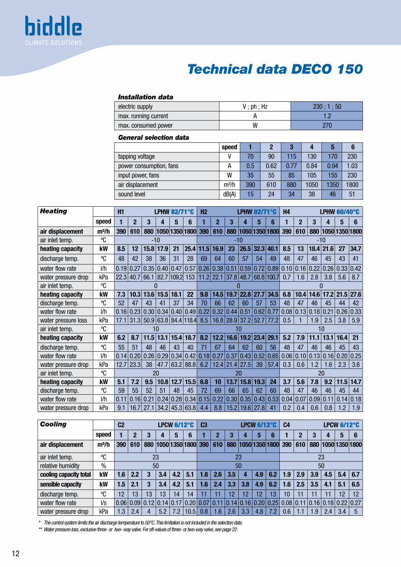
Technical data DECO 150
Installation dataelectric supply V ; ph ; Hz 230 ; 1 ; 50 max. running current A 1.2max. consumed power W 270
General selection data speed 1 2 3 4 5 6tapping voltage V 70 90 115 130 170 230power consumption, fans A 0.5 0.62 0.77 0.84 0.94 1.03input power, fans W 35 55 85 105 155 230air displacement m³/h 390 610 880 1050 1350 1800sound level dB(A) 15 24 34 38 46 51
Heating H1 LPHW 82/71°C H2 LPHW 82/71°C H4 LPHW 60/40°Cspeed 1 2 3 4 5 6 1 2 3 4 5 6 1 2 3 4 5 6
air displacement m³/h 390 610 880 1050 1350 1800 390 610 880 1050 1350 1800 390 610 880 1050 1350 1800air inlet temp. ºC -10 -10 -10heating capacity kW 8.5 12 15.8 17.9 21 25.4 11.5 16.9 23 26.5 32.3 40.1 8.5 13 18.4 21.6 27 34.7discharge temp. ºC 48 42 38 36 31 28 69 64 60 57 54 49 48 47 46 45 43 41
water flow rate l/h 0.19 0.27 0.35 0.40 0.47 0.57 0.26 0.38 0.51 0.59 0.72 0.89 0.10 0.16 0.22 0.26 0.33 0.42water pressure drop kPa 22.3 40.7 66.1 82.7 109.2 153 11.2 22.1 37.8 48.7 68.8 100.7 0.7 1.6 2.8 3.8 5.6 8.7air inlet temp. ºC 0 0 0heating capacity kW 7.3 10.3 13.6 15.5 18.1 22 9.8 14.5 19.7 22.8 27.7 34.5 6.8 10.4 14.6 17.2 21.5 27.6discharge temp. ºC 52 47 43 41 37 34 70 66 62 60 57 53 48 47 46 45 44 42water flow rate l/h 0.16 0.23 0.30 0.34 0.40 0.49 0.22 0.32 0.44 0.51 0.62 0.77 0.08 0.13 0.18 0.21 0.26 0.33water pressure loss kPa 17.1 31.3 50.9 63.8 84.4 118.4 8.5 16.8 28.9 37.2 52.7 77.2 0.5 1 1.9 2.5 3.8 5.9air inlet temp. ºC 10 10 10heating capacity kW 6.2 8.7 11.5 13.1 15.4 18.7 8.2 12.2 16.6 19.2 23.4 29.1 5.2 7.9 11.1 13.1 16.4 21discharge temp. ºC 55 51 48 46 43 40 71 67 64 62 60 56 48 47 46 46 45 43water flow rate l/h 0.14 0.20 0.26 0.29 0.34 0.42 0.18 0.27 0.37 0.43 0.52 0.65 0.06 0.10 0.13 0.16 0.20 0.25water pressure drop kPa 12.7 23.3 38 47.7 63.2 88.8 6.2 12.4 21.4 27.5 39 57.4 0.3 0.6 1.2 1.6 2.3 3.6air inlet temp. ºC 20 20 20heating capacity kW 5.1 7.2 9.5 10.8 12.7 15.5 6.8 10 13.7 15.8 19.3 24 3.7 5.6 7.8 9.2 11.5 14.7discharge temp. ºC 59 55 52 51 48 45 72 69 66 65 62 60 48 47 46 46 45 44water flow rate l/h 0.11 0.16 0.21 0.24 0.28 0.34 0.15 0.22 0.30 0.35 0.43 0.53 0.04 0.07 0.09 0.11 0.14 0.18water pressure drop kPa 9.1 16.7 27.1 34.2 45.3 63.8 4.4 8.8 15.2 19.6 27.8 41 0.2 0.4 0.6 0.8 1.2 1.9
Cooling C2 LPCW 6/12°C C3 LPCW 6/12°C C4 LPCW 6/12°Cspeed 1 2 3 4 5 6 1 2 3 4 5 6 1 2 3 4 5 6
air displacement m³/h 390 610 880 1050 1350 1800 390 610 880 1050 1350 1800 390 610 880 1050 1350 1800
air inlet temp. ºC 23 23 23relative humidity % 50 50 50cooling capacity total kW 1.6 2.2 3 3.4 4.2 5.1 1.8 2.6 3.5 4 4.9 6.2 1.9 2.9 3.9 4.5 5.4 6.7sensible capacity kW 1.5 2.1 3 3.4 4.2 5.1 1.6 2.4 3.3 3.8 4.9 6.2 1.6 2.5 3.5 4.1 5.1 6.5discharge temp. ºC 12 13 13 13 14 14 11 11 12 12 12 13 10 11 11 11 12 12water flow rate l/s 0.06 0.09 0.12 0.14 0.17 0.20 0.07 0.11 0.14 0.16 0.20 0.25 0.08 0.11 0.16 0.18 0.22 0.27water pressure drop kPa 1.3 2.4 4 5.2 7.2 10.5 0.8 1.6 2.6 3.3 4.8 7.2 0.6 1.1 1.9 2.4 3.4 5
* The control system limits the air discharge temperature to 50°C. This limitation is not included in the selection data.** Water pressure loss, exclusive three- or two- way valve. For sft-values of three- or two-way valve, see page 22.

13
* With electric heating, the heating capacity is 5% lower than the installed power.
Technical data DECO HE
Installation data
DECO 50 DECO 100 DECO 150 electric supply 400 V; 3 ph; 50 Hz 400 V; 3 ph; 50 Hz 400 V; 3 ph; 50 Hzmax. running current A 10.4 16 23.8max. consumed power kW 7.1 10.7 15.9heating*
General selection data
DECO 50 DECO 100 DECO 150 speed 1 2 3 4 5 6 1 2 3 4 5 6 1 2 3 4 5 6tapping voltage V 70 90 115 130 170 230 70 90 115 130 170 230 70 90 115 130 170 230power consumption, fans A 0.14 0.19 0.24 0.26 0.29 0.34 0.33 0.41 0.51 0.56 0.63 0.69 0.5 0.62 0.77 0.84 0.94 1.03input power, fans W 10 20 30 35 50 75 25 40 60 70 105 155 35 55 85 105 155 230air displacement m3/h 140 205 315 350 450 605 275 405 635 700 900 1180 390 610 880 1050 1350 1800sound level dB(A) 15 24 33 38 45 51 15 24 34 38 46 51 15 24 34 38 46 51
1 At some fan speeds, the available heating capacity may be higher than the real heating capacity, as the control system limits the outlet air temperature tot 50°C.* The DECO 75 and DECO 125 are not available as electrically heated units.
DECO 50 DECO 100 DECO 150 HE 400 V HE 400 V HE 400 V Speed 1 2 3 4 5 6 1 2 3 4 5 6 1 2 3 4 5 6air displacement m³/h 140 205 315 350 450 605 275 405 635 700 900 1180 390 610 880 1050 1350 1800available heating cap.1 kW 6.6 10 14.8max. power consumption per phase
A 10.1 15.2 22.5
air inlet temperature ºC -10 -10 -10discharge temperature ºC 50 50 46 41 29 19 50 50 32 28 20 13 50 50 35 28 19 12real heating capacity kW 3.1 4.6 6.6 6.6 6.6 6.6 6.2 9.1 10 10 10 10 8.8 13.7 14.8 14.8 14.8 14.8air inlet temperature ºC 0 0 0discharge temperature ºC 50 50 50 50 41 30 50 50 44 40 31 23 50 50 47 39 30 23real heating capacity kW 2.5 3.7 5.7 6.3 6.6 6.6 5 7.3 10 10 10 10 7 11 14.8 14.8 14.8 14.8air inlet temperature ºC 10 10 10discharge temperature ºC 50 50 50 50 50 42 50 50 50 50 42 34 50 50 50 50 42 34real heating capacity kW 1.9 2.8 4.4 4.8 6.2 6.6 3.8 5.6 8.8 9.7 10 10 5.4 8.4 12.2 14.5 14.8 14.8air inlet temperature ºC 20 20 20discharge temperature ºC 50 50 50 50 50 50 50 50 50 50 50 45 50 50 50 50 50 45real heating capacity kW 1.4 2.1 3.2 3.5 4.5 6.1 2.8 4.1 6.4 7 9 10 3.9 6.1 8.8 10.6 13.6 14.8
Electrical heating

14
Explanation of technical dataCorrection coefficients- heating capacity
The heating capacities for the coil types H1 and H2 listed in the tables on pages 8 to 12 are based on a water temperature range of 82/71°C. The heating capacities for the coil type H4 are based on a water temperature range of 60/40°C.
If water temperatures differ, the heating capacity is to be multiplied by the coefficients from the below tables. These coefficients are applicable to the heating capacities from the tables on pages 8 to 12 at an inlet air temperature of 20°C. The first table lists the correction coefficients for the coil types H1 and H2. The correction coefficients for the coil type H4 are listed in the second table.
Correction coefficients - cooling capacity
The cooling capacities for the coil types C2, C3 and C4 listed in the tables on pages 8 to 12 are based on a water temperature range of 6/12°C and on an inlet air temperature of 23°C at 50% R.H. If water temperatures and inlet air conditions differ, the cooling capacity is to be multiplied by coefficients from the table on page 15.
Explanation
The correction coefficients are for the capacities listed in the tables on page 8 to 12. They give an indication of the capacity at deviating water temperatures and air conditions. For exact data, please seek the advice of a Biddle employee.
Correction coefficients for heating capacities of the battery types H1 and H2
H1/H2 Air inlet temperature -10 ºC 0 ºC 10 ºC 20 ºC90/70 ºC 1.67 1.45 1.23 1.0282/71 ºC 1.65 1.43 1.21 180/60 ºC 1.46 1.24 1.03 0.8270/50 ºC 1.25 1.03 0.83 0.6260/40 ºC 1.04 0.83 0.62 0.4350/40 ºC 1.01 0.8 0.59 0.450/30 ºC 0.83 0.62 0.42 0.23
Correction coefficients for heating capacity of the battery type H4
H490/70 ºC 3.8 3.25 2.74 2.2682/71 ºC 3.72 3.17 2.67 2.1980/60 ºC 3.34 2.81 2.31 1.8470/50 ºC 2.88 2.36 1.88 1.4260/40 ºC 2.42 1.92 1.45 150/40 ºC 2.3 1.81 1.34 0.950/30 ºC 1.95 1.47 1.01 0.54

Explanation of technical data
C2, C3 and C4LPCW Air inlet
temp.Relative Humidity
40% R.H. 50% R.H. 60% R.H.Qt Qs Qt Qs Qt Qs
6/12 °C 22 °C 0.91 0.91 0.91 0.91 1.01 0.86
23 °C 1 1 1 1 1.21 0.94
24 °C 1.09 1.09 1.09 1.09 1.42 1.02
27 °C 1.34 1.34 0.63 1.27 2.06 1.24
28 °C 1.42 1.42 0.84 1.35 2.29 1.31
8/14 °C 22 °C 0.75 0.75 0.75 0.75 0.75 0.75
23 °C 0.83 0.83 0.83 0.83 0.83 0.83
24 °C 0.92 0.92 0.92 0.92 1.02 0.86
27 °C 1.17 1.17 1.24 1.12 1.67 1.09
28 °C 1.26 1.26 1.44 1.2 1.89 1.16
10/16 °C 22 °C 0.57 0.57 0.57 0.57 0.57 0.57
23 °C 0.66 0.66 0.66 0.66 0.66 0.66
24 °C 0.75 0.75 0.75 0.75 0.75 0.75
27 °C 1 1 1 1 1.24 0.94
28 °C 1.09 1.09 1.09 1.09 1.47 1.01
12/18 °C 22 °C 0.39 0.39 0.39 0.39 0.39 0.39
23 °C 0.49 0.49 0.49 0.49 0.49 0.49
24 °C 0.58 0.58 0.58 0.58 0.58 0.58
27 °C 0.84 0.84 0.84 0.84 0.84 0.84
28 °C 0.92 0.92 0.92 0.92 1.02 0.86
Water flow rate
The water flow rates listed in the tables on pages 8 to 12 are based on a water temperature range of 82/71°C, 50/30°C or 60/40°C. If water flow rates differ from those listed in the tables on pages 8 to 12, the water flow rate may be roughly calculated using the opposite formula. Before doing so, the heating capacity must first be recalculated (see page 14).
Water pressure loss
AIl water temperatures differ from those listed in the tables on pages 8 to 12, then the water pressure loss may be roughly calculated using the formula below. To do so, the water flow rate must first be calculated (see above).
15
Correction factors cooling capacity coil types C2, C3 and C4.
Qt = total cooling capacity Qv = sensible cooling capacity
mw = • 3600 [ l /h ] Q
ρw C pw ∆Tw
mw = water flow rate [l/h]Q = capacity [kW] (page 14)ρw = density of water [kg/l]Cpw = specific heat of water (= 4.18) [kJ/kg°C]∆Tw = temperature difference water [°C]
∆pw1 = water pressure loss, table
values [kPA]∆pw2
= water pressure loss [kPA]mw1
= water flow rate, table values [l/h]mw2
= water flow rate calculated using formula [l/h]
∆ pw2 = ∆pw1 [kPa]( )2
mw1
mw2

Explanation of Technical dataSound
In the tables on pages 8 to 13, a sound level in the reverberation field is listed for all six speeds. These sound level values are based on the use of one fan coil unit in a reference room.
Reference room
For each type of fan coil unit, a room has been taken for expressing the noise level. The reference room (Vo) is chosen dependent on the size of the unit, such that the air circulation ratio in the room is equal to 2 at fan speed 4. The reference room is stated in the opposite table. As many offices have sound-absorbing ceilings, an average reverberation time of 0.5 second has been assumed.
Deviating room and multiple units
If a unit is used in a deviating room or if multiple units are used in a single room, the sound level must be recalculated. This can be done using the below formula, whereby the relevant table value can be retrieved from the tables on pages 8 to 13 (general selection data per speed).
Sample calculation
Wanted: the noise level in the reverberation field if three DECO 75 fan coil units are used at speed 3 in a room featuring a reverberation time of 0.6 second and a volume of 600 m3.
= 34 + (0.8-3.7+4.8) = 35,9 dB(A)
) ( Lp = table value + 10 • log -10 • log
+10 • log (n) [dB(A)]
16
Unit size Reference room DECO 50 175 m3
DECO 75 258 m3
DECO 100 350 m3
DECO 125 420 m3
DECO 150 525 m3
Lp = sound pressure [dB(A)]T = reverberation value in deviating room [s]T0 = reverberation value is 0.5 sV = volume of deviating room [m3]V0 = volume reference room [m3] (see table)n = number of units
( ( ) ) T0
T VV0
34 + 10 • log -10 • log +10 • log (n) ( ( ) ) 0.5 258( ) 0.6 600

17
Explanation of technical dataOverview of sound data
Unit size Sound pres- Sound power level** sure level* in dB(A) Per octave band in the medium frequency in dB (ref 1 x 10-12W) in dB(A) Type Speed Lp 63 Hz 125 Hz 250 Hz 500 Hz 1000 Hz 2000 Hz 4000 Hz 8000 Hz LwDECO 50 1 15 30.3 32.4 30.7 25.4 16.3 8.9 0 0 26.3 2 23.8 33.7 39.7 37.4 34.5 28.6 23.7 10.3 0 35.3 3 33.3 38.9 47.5 44.5 43.1 39.2 6.9 25.9 14.5 44.8 4 37.9 41.5 51.6 48.5 46.6 44.2 42.4 33.5 23 49.4 5 45.4 47.2 58.1 55 53.1 51.2 50.9 45 36.1 56.9 6 50.6 51.2 62.6 60 57.6 56.7 55.9 51.5 44.1 62.1DECO 75 1 14.1 34.1 33.8 29.7 27.6 15.4 11.7 0 0 27.2 2 26.5 40.5 42.3 44.5 38.5 30.1 23.7 12 0 39.6 3 34 45.8 48.9 45.5 46.6 41.7 36.9 27.4 12.2 47 4 38.6 47.9 53.4 50 50.6 46.7 42.4 35 21.4 51.7 5 46.2 53.5 59.9 56 57.1 54.7 51.4 46 34.5 59.3 6 50.8 58 64.9 61 61.1 58.7 56.9 52 43 63.9DECO 100 1 14.8 35.6 35.1 32.2 29.4 19.8 12.4 0.8 0 29.3 2 24.1 39.1 42.4 38.9 38.5 32.1 27.2 13.3 1.6 38.6 3 33.7 44.2 50.2 46 47.1 42.7 40.4 28.9 18.1 48.2 4 38.3 46.9 54.2 50 50.6 47.7 45.9 36.5 26.6 52.8 5 45.8 52.5 60.7 56.5 57.1 54.7 54.4 48 39.6 60.3 6 51 56.5 65.2 61.5 61.6 60.2 59.4 54.5 47.6 65.5DECO 125 1 13.7 35.7 34.9 30.5 29.6 19.7 10.4 0 0 29 2 23.4 39.7 42.3 40.9 39 30.8 23.9 9 0 38.7 3 31.8 43.3 49.3 46 46.1 42.2 37.3 25.8 13.6 47.1 4 36.8 46.5 52.9 50.5 50.6 47.2 43.9 34 20.6 52.1 5 45 51.7 59.9 57 57.1 55.7 53.4 47 36.1 60.3 6 51.4 56.7 66.4 62.5 63.1 61.7 60.4 55 46.6 66.7DECO 150 1 15 36.9 37.3 33.7 31.4 21.3 13.9 2.9 0 31.2 2 24.2 40.4 44.6 40.4 40.5 33.6 28.7 15.3 2.2 40.4 3 33.8 45.5 52.4 47.5 49.1 44.2 41.9 30.9 18.6 50 4 38.3 48.2 56.4 51.5 52.6 49.2 47.4 38.5 27.1 54.5 5 45.8 53.8 62.9 58 59.1 56.2 55.9 50 40.1 62 6 51 57.8 67.4 63 63.6 61.7 60.9 56.5 48.2 67.2
* The noise levels are based on the reverberation field in a reference room (see page 16).** The value <0 indicates that the relevant value is below the threshold of hearing.

18
Explanation of Technical dataSound-damping air inlet section
To reduce the noise, a sound-damping air inlet section can be installed in units that feature outside-air inlet. The section reduces both the outside noise coming in, such as traffic noise, and the inside noise going out, such as bar noise. The inner side of the sound-damping inlet section is finished with a sound-absorbing open-cell foam coat. The sound damping values have been measured according to NEN 20140 at the laboratory of the Groningen-based firm Van Dorsser BV (The Netherlands).
The values from the table below can be used for a simplified calculation.
Damping value - sound power level [dB]Mode Dn*, referenced to 10 m2
per octave band in the medium frequence Total 125 Hz 250 Hz 500 Hz 1000 Hz 2000 Hz 4000 Hz LWDamper actuator in ventilation mode 25 21 28 36 37 48 29Damper actuator in recirculation mode 24 23 33 37 37 49 31* Dn is damping valve
Damping value, - sound level differential per octave
Recirculation
Ventilation
0
10
20
30
40
50
60
4000 Hz2000 Hz1000 Hz500 Hz250 Hz125 Hz
nD [d
B]
Damping value - sound power level [dB(A)]Mode RA,netto*
DECO 50 DECO 75 DECO 100 DECO 125 DECO 150Damper actuator in ventilation mode 6 8 10 11 11Damper actuator in recirculation mode 8 10 12 13 13wall duct [m2] 0.061 0.093 0.12 0.16 0.19* RA,netto is the sound reduction per type of sound-damping air inlet section.

19
20127
127
20
5212
7
84
21
280 B
650
5-20
*
280
A
41 239 B 239 41
2524
8
Curved plastic side covers
Filter frame
Adjustable discharge grille
Removable to lead lines through
Floor model, ceiling model also available
Adjusting foot
Inlet grille
Notes:• All dimensions in mm. * Adjusting size for adjusting feet. Only the floor model comes with adjusting feet.
Unit size A BDECO 50 1042 482DECO 75 1292 732DECO 100 1542 982DECO 125 1792 1232DECO 150 2042 1482
20127
127
20
5212
7
84
21
280 B
650
5-20
*
280
A
41 239 B 239 41
2524
8
Curved plastic side covers
Filter frame
Adjustable discharge grille
Removable to lead lines through
Floor model, ceiling model also available
Adjusting foot
Inlet grille
20127
127
20
5212
7
84
21
280 B
650
5-20
*
280
A
41 239 B 239 41
2524
8
Curved plastic side covers
Filter frame
Adjustable discharge grille
Removable to lead lines through
Floor model, ceiling model also available
Adjusting foot
Inlet grille
20127
127
20
5212
7
84
21
280 B
650
5-20
*
280
A
41 239 B 239 4125
248
Curved plastic side covers
Filter frame
Adjustable discharge grille
Removable to lead lines through
Floor model, ceiling model also available
Adjusting foot
Inlet grille
Dimensional sketches of stylish model (S)Depicted model DECO 50-HIC3-R-FS10
= inspection side = air directionSee page 5, figure 1
FS2 FS8
Recirculation Ventilation Recirculation/Ventilation
CS6 CS8
FS10
CS10 CS12
FS12FS6
CS2

20
248
2541239
A
B41 2395-
20*
650
507
**
21
20
2012
7
144
81
127280B280
Straight metal side covers
Filter frame
Adjustable discharge grille
Removable to lead lines through
Floor model, ceiling model also available
Adjusting foot
FB4
Inlet grille
Notes:• All dimensions in mm. * Adjusting size for adjusting feet. Only the floor model comes with adjusting feet. ** Applies only for encased floor model for recirculation, type FB4. The minimum distance between floor and unit will then be 120 mm.
Unit size A BDECO 50 1042 482DECO 75 1292 732DECO 100 1542 982DECO 125 1792 1232DECO 150 2042 1482
248
2541239
A
B41 239
5-20
*65
0 5
07**
21
20
2012
7
144
81
127280B280
Straight metal side covers
Filter frame
Adjustable discharge grille
Removable to lead lines through
Floor model, ceiling model also available
Adjusting foot
FB4
Inlet grille
Dimensional sketches of business model (B) Depicted model DECO 50-HIC3-R-FB10
248
25
41239
A
B41 239
5-20
*65
0 5
07**
21
20
2012
7
144
81
127280B280
Straight metal side covers
Filter frame
Adjustable discharge grille
Removable to lead lines through
Floor model, ceiling model also available
Adjusting foot
FB4
Inlet grille
FB2 FB8
Recircltaion Ventilation Recirculation/Ventilation
CB6 CB8
FB10
CB10 CB12
FB12FB6FB4
CB2
= inspection side = air directionSee page 5, figure 1
21
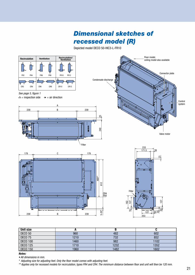
Notes:• All dimensions in mm. * Adjusting size for adjusting feet. Only the floor model comes with adjusting feet. ** Applies only for recessed models for recirculation, types FR4 and CR4. The minimum distance between floor and unit will then be 120 mm.
Unit size A B CDECO 50 960 482 602DECO 75 1210 732 852DECO 100 1460 982 1102DECO 125 1710 1232 1352DECO 150 1960 1482 1602
Dimensional sketches of recessed model (R)Depicted model DECO 50-HIC3-L-FR10
Recirculation Ventilation Recirculation/Ventilation
CR2 CR4 CR6 CR8 CR10 CR12
FR4FR2 FR6 FR8 FR10 FR12
= inspection side = air directionSee page 5, figure 1
Floor model, ceiling model also available
Condensate discharge
Connector plate
Control system
Valve motor
239
179
239 239253
127 201612
716
2
127
15
39171.5233
2025
B
179
CR4FR4
612
5-20
*46
9**
C
239
2524
0
B
A
Filter
Filter
Floor model, ceiling model also available
Condensate discharge
Connector plate
Control system
Valve motor
239
179
239 239253
127 201612
716
2
127
15
39171.5233
2025
B
179
CR4FR4
612
5-20
*46
9**
C
239
2524
0
B
A
Filter
Filter
Floor model, ceiling model also available
Condensate discharge
Connector plate
Control system
Valve motor
239
179
239 239253
127 201612
716
2
127
15
39171.5233
2025
B
179
CR4FR4
612
5-20
*46
9**
C
239
2524
0
B
A
Filter
Filter

22
Notes:• All dimensions in mm.• With sizes B and C, minor deviations of 5mm at the most may occur.* Kvs values for 3- and 2-way valves. Where values vary, the 3-way valve is mentioned first, followed by the 2-way valve. ** Adjusting size for adjusting feet. Only the floor model comes with adjusting feet. *** Size for H1-connection if H1C3 is used. - pipe diameter squeezed joint DN 15: 15 mm, DN 20: 22 mm. - pipe connection can be made to both the left- and the right-hand side of the unit.
158
288
213
5-20
**
158 41
58***
100-105
B*** 40
C 40
41 A
Straight side covers (model Business)
Curved side covers (model Stylish)
Hole in bottom to lead lines through
Key holes for mounting
Condensate discharge ø 15 mm
Squeezed joints
Return
Supply
Heating for 4-pipes H1C3
Cooling for 4-pipes H1C3Cooling or heating for 2-pipes
Unit size Coil types H1 H2 H4 C2 C3 C4 Kvs* DN Kvs* DN Kvs* DN Kvs* DN Kvs* DN Kvs* DNDECO 50 0.63 15 1 15 1.6 15 1 15 1.6 15 1.6 15DECO 75 0.63 15 1 15 1.6 15 1 15 1 15 1.6 15 DECO 100 1.6 15 3/2.5 20 3/3.5 20 1.6 15 3/3.5 20 3/3.5 20DECO 125 1 15 3/2.5 20 3/3.5 20 1.6 15 3/3.5 20 3/3.5 20DECO 150 1 15 2.5 20 3/3.5 20 1.6 15 3/2.5 20 3/3.5 20
Unit size A DECO 50 644 DECO 75 894 DECO 100 1144 DECO 125 1394 DECO 150 1644
Dimensional sketches water connections Depicted model DECO 50-HIC3-L-FR6
Coil types B C H1, H2, C2 - 129 C3 - 138 H4, C4 - 147 H1C3 126 145

23
Dimensional sketches of attenuated air inlet section Depicted DECO 50
Unit size A B CDECO 50 963 482 503DECO 75 1213 732 753DECO 100 1463 982 1003DECO 125 1713 1232 1253DECO 150 1963 1482 1503
Notes:• All dimensions in mm.• Available for Ceiling and Wall models.• Holes for mounting are situated at the back site of the unit (see page 22).
371
142x
C45
1.5
- 46
6.5
454
127
33.5
2212221
614.
5
240.5240.5 B
A
371
142x
C45
1.5
- 46
6.5
454
127
33.5
2212221
614.
5
240.5240.5 B
A
37114
2xC
451.
5 -
466.
5
454
127
33.5
2212221
614.
5
240.5240.5 B
A
371
142x
C45
1.5
- 46
6.5
454
127
33.5
2212221
614.
5
240.5240.5 B
A

24
230
826
A
C
214
171.
549
4.7
127
259
253
B
Dimensional sketches discharge section and plenum Depicted DECO 50-H1C3-L-FR10Discharge section*
Material: zinc coated plate steel
Unit size A B CDECO 50 645 602 482DECO 75 895 852 732DECO 100 1145 1102 982DECO 125 1395 1352 1232DECO 150 1645 1602 1482
Notes:• All dimensions are in mm.* The discharge section is used in recessed models to switch from top discharge to front discharge. * The discharge section may be used with a flexible connection sleeve (see page 26) or a grille (page 26).
Air inlet plenum for FRC/CR4Unit size A Spouts C
DECO 50 597 2 300DECO 75 847 3 300DECO 100 1097 4 270DECO 125 1347 5 275DECO 150 1597 6 265
Discharge plenumUnit size A B Spouts C
DECO 50 645 601 2 300DECO 75 895 851 3 300DECO 100 1145 1101 4 270DECO 125 1395 1351 5 275DECO 150 1645 1601 6 265
ø 200
B
A
228
ø 200
232
A
7942
7927
.546
930
79
ø 200
B
A
228
ø 200
232
A
7942
7927
.546
930
79
Air inlet and discharge plenumMaterial: zinc coated plate steel
Air inlet plenum for CR4/FR4Discharge section

25
171.5
204.5
127
180
55-155
55-1
55
D
A
B
C
*
* *
Unit size A B C DDECO 50 645 602 482 534DECO 75 895 852 732 784DECO 100 1145 1102 982 1034DECO 125 1395 1352 1232 1284DECO 150 1645 1602 1482 1534
Dimensional sketches flexible connection sleevesDepicted DECO 50-H1C3-L-FR10
Remarks:• All dimensions in mm. • Material: PVC-coated polyester tissue (bisonyl)* Available with or without duct connection flange (made of zinc plated sheet steel). Connection sleeves are delivered unit-mounted.

26
Dimensional sketches of wall and ceiling grilles Depicted for model DECO 50
Adjustable discharge grilleMaterial: painted zinc plated sheet steel.
Fin grillesMaterial: natural-coloured, extruded, anodised aluminium, includes a fixing frame with recessed holes.Available in three types:
1. Double adjustable grille
2. Single adjustable grille
3. Fixed grille
Notes:• These grilles can be used for both in- and outlet sides. On the outlet side, the grille is mounted onto the unit using a flange.
B
A 46
6
6
6
160
114
B
A 26
160
109
B
A 26
167
118.
5
B
A 46
6
6
6
160
114
B
A 26
160
109
B
A 26
167
118.
5
B
A 46
6
6
6
160
114
B
A 26
160
109
B
A 26
167
118.
5
52.5
156
C
A
206.
5
B
38.552.5
156
C
A
206.
5
B
38.5
52.5
156
C
A
206.
5
B
38.5
B
A 46
6
6
6
160
114
B
A 26
160
109
B
A 26
167
118.
5B
A 46
6
6
6
160
114
B
A 26
160
109
B
A 26
167
118.
5
Unit size A B CDECO 50 645 623 602DECO 75 895 873 852DECO 100 1145 1123 1102DECO 125 1395 1373 1352DECO 150 1645 1623 1602All dimensions are in mm.
Unit size A BDECO 50 515 469DECO 75 765 719DECO 100 1015 969DECO 125 1265 1219DECO 150 1515 1469All dimensions are in mm.
Unit size A BDECO 50 515 469DECO 75 765 719DECO 100 1015 969DECO 125 1265 1219DECO 150 1515 1469All dimensions are in mm.
Unit size A BDECO 50 528 477DECO 75 778 727DECO 100 1028 977DECO 125 1278 1227DECO 150 1528 1477All dimensions are in mm.

27
530
319
139
145
C
B70 70 7070
70
600
325
50
445
Wire grid
Removable cover
A
Threaded connection, to be drilled after removal of rain cap
Architectural roof upstand finished with roofing.
Dimensional sketches wall and roof ducts Depicted model DECO 50
530
319
139
145
C
B70 70 7070
70
600
325
50
445
Wire grid
Removable cover
A
Threaded connection, to be drilled after removal of rain cap
Architectural roof upstand finished with roofing.
Roof cap and roof ductMaterial: 1.5 mm aluminium sheet
530
319
139
145
C
B70 70 7070
70
600
325
50
445
Wire grid
Removable cover
A
Threaded connection, to be drilled after removal of rain cap
Architectural roof upstand finished with roofing.
Unit Size A B CDECO 50 494 503 678DECO 75 744 753 928DECO 100 994 1003 1178DECO 125 1244 1253 1428DECO 150 1494 1503 1678All dimensions in mm
Wall grate
Unit size A B C D EDECO 50 529 478 500 503 491DECO 75 779 728 750 753 741DECO 100 1029 978 1000 1003 991DECO 125 1279 1228 1250 1253 1241DECO 150 1529 1478 1500 1503 1491
Wall duct Outside Inside
46 200 206
205-355
A B C D E
Wall grate Wall duct Wall duct
178
127
176
139
142
17.5
-32.
5
133
170
6
of 350-650
Top view
Side view
Wall duct and wall grateMaterial: zinc coated plate steel
DECO
.NE-
uk.2
014-
11.P
DF•1
4102
842-
1
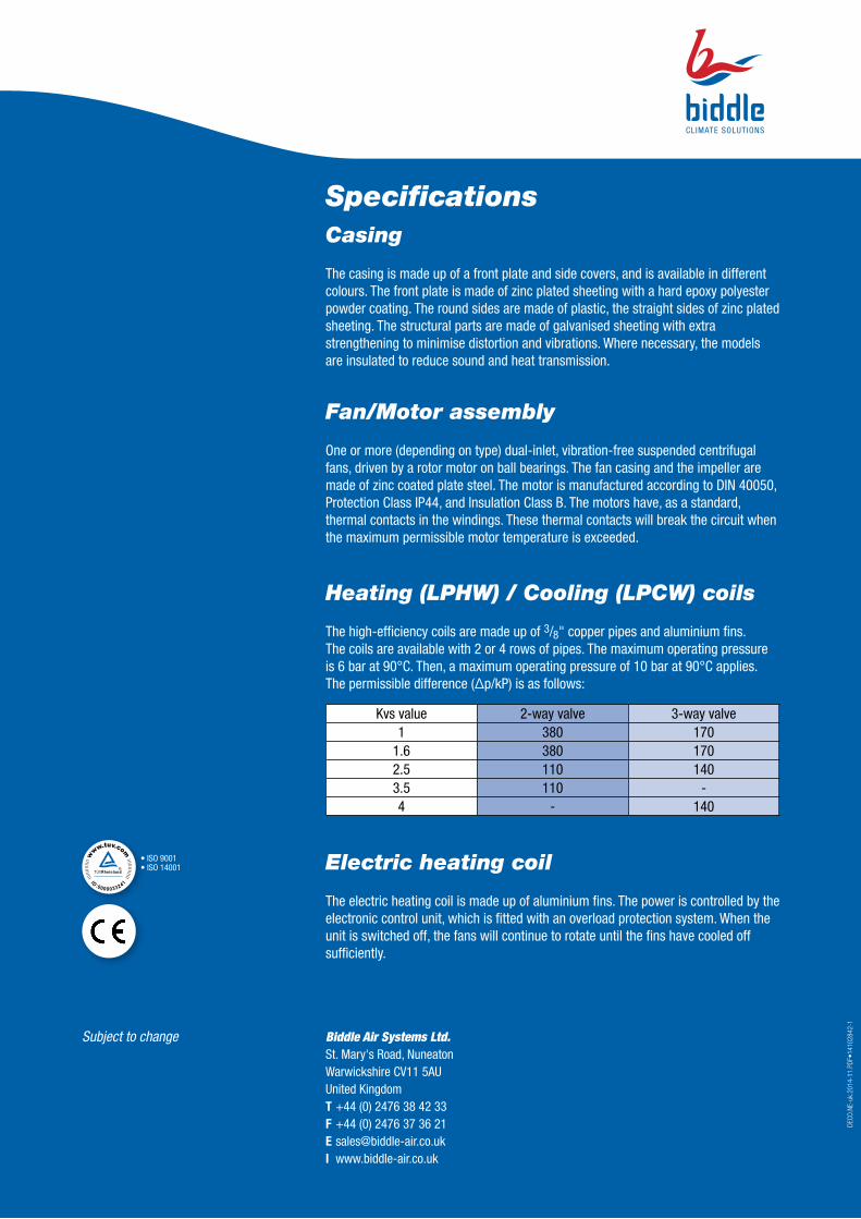
SpecificationsCasing
The casing is made up of a front plate and side covers, and is available in different colours. The front plate is made of zinc plated sheeting with a hard epoxy polyester powder coating. The round sides are made of plastic, the straight sides of zinc plated sheeting. The structural parts are made of galvanised sheeting with extra strengthening to minimise distortion and vibrations. Where necessary, the models are insulated to reduce sound and heat transmission.
Fan/Motor assembly
One or more (depending on type) dual-inlet, vibration-free suspended centrifugal fans, driven by a rotor motor on ball bearings. The fan casing and the impeller are made of zinc coated plate steel. The motor is manufactured according to DIN 40050, Protection Class IP44, and Insulation Class B. The motors have, as a standard, thermal contacts in the windings. These thermal contacts will break the circuit when the maximum permissible motor temperature is exceeded.
Heating (LPHW) / Cooling (LPCW) coils
The high-efficiency coils are made up of 3/8" copper pipes and aluminium fins. The coils are available with 2 or 4 rows of pipes. The maximum operating pressure is 6 bar at 90°C. Then, a maximum operating pressure of 10 bar at 90°C applies.The permissible difference (Δp/kP) is as follows:
Electric heating coil
The electric heating coil is made up of aluminium fins. The power is controlled by the electronic control unit, which is fitted with an overload protection system. When the unit is switched off, the fans will continue to rotate until the fins have cooled off sufficiently.
• ISO 9001• ISO 14001
Subject to change Biddle Air Systems Ltd.St. Mary's Road, NuneatonWarwickshire CV11 5AUUnited KingdomT +44 (0) 2476 38 42 33F +44 (0) 2476 37 36 21E [email protected] www.biddle-air.co.uk
Kvs value 2-way valve 3-way valve1 380 170
1.6 380 1702.5 110 1403.5 110 - 4 - 140