false color suppression in demosaiced color images
TRANSCRIPT
False Color Suppression in Demosaiced Color Images
Jayanta Mukherje Manfred K. Lan S. K. MitraDepartment of Computer Institute for Human- Department of Electrical
Science & Engg. -Machine Communication & Computer Engg. IndianInstituteofTechnology TechnicalUniversityofMunich, UniversityofCalifornia
Kharagpur, INDIA-721302 D-80290, Munich, Germany Santa Barbara, 93106, [email protected] [email protected] [email protected]
Abstract
In a single-chip digital color camera, a color filter array(CFA) is used to obtain sampled spectral components (red,green and blue) in an interleaved fashion. A color demo-saicing operation is then carried out to determine the miss-ing spectral components at every location. One of the prob-lems in color demosaicing is that many of the interpolatedimages are affected by colored artifacts near the edges cre-ating false colors. The problem is more severe if the edgesare achromatic. In this paper we propose the use of medianfiltering for suppressing this phenomenon. We have con-sidered a set of existing interpolation algorithms and pre-sented their performances in interpolating mosaiced pat-terns. Next we have carried out median filtering of thechrominance components of the demosaiced images. Ineach case, the post-processing has remarkably improved thequality of the reconstructions. The observations are verifiedby both quantitative measures for expressing the quality ofreconstruction as well as by visual examinations of the re-constructed images.
1. Introduction
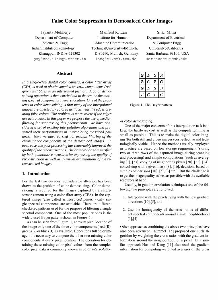
For the last two decades, considerable attention has beendrawn to the problem of color demosaicing. Color demo-saicing is required for the images captured by a single-sensor camera using a color filter array (CFA). In the cap-tured image (also called as mosaiced pattern) only sin-gle spectral components are available. There are differentcheckered patterns used for the purpose of filtering a singlespectral component. One of the most popular ones is thewidely used Bayer pattern shown in Figure 1.
As can be seen from Figure 1, at every pixel location ofthe image only one of the three color components ( red (R),green (G) or blue (B)) is available. Hence for a full color im-age, it is necessary to compute the other two missing colorcomponents at every pixel location. The operation for ob-taining these missing color pixel values from the sampledcolor pixel data is commonly known as color interpolation
� � � �
� � � �
� � � �
� � � �
Figure 1: The Bayer pattern.
or color demosaicing.One of the major concerns of this interpolation task is to
keep the hardware cost as well as the computation time assmall as possible. This is to make the digital color imag-ing (for both still and video images) cost-effective and tech-nologically viable. Hence the methods usually employedin practice are based on low storage requirement (storingtwo or three rows of the captured image during scanningand processing) and simple computations (such as averag-ing [1], [23], copying of neighboring pixels [20], [21], [24],convolving with a given mask [8], [16], decisions based onsimple comparisons [10], [5], [3] etc.). But the challenge isto get the image quality as best as possible with the availableresources at hand.
Usually, in good interpolation techniques one of the fol-lowing two principles are followed:
1. Interpolate with the pixels lying with the low gradientdirections [10],[5], and
2. Use the homogeneity of the cross-ratios of differ-ent spectral components around a small neighborhood[1],[4].
Other approaches combining the above two principles havealso been advanced. Kimmel [15] proposed one such al-gorithm by weighting the cross-ratios with the gradient in-formation around the neighborhood of a pixel. In a sim-ilar approach Hur and Kang [11] also used the gradientinformation for computing weighted averages of the cross

ratios and recovering the spectral component from it. In[17] also, relatively faster algorithms combining the abovetwo principles are designed for interpolating color images.The approaches are adopted for processing with two rowsor three rows of the mosaiced patterns. Accordingly, theyare called as Two-Line Algorithm (2L) and Three-Line Al-gorithm (3L).
One of the problems associated with color interpolationis the appearances of false colors or colored artifacts nearthe edges. The problem gets more severe if the edges areachromatic (of grey shades). A typical example is demon-strated in Figure 2. The original image is shown in Figure2(a). A mosaiced pattern following the Bayer CFA is gener-ated from it and then interpolated using the bilinear interpo-lation algorithm. The interpolated image is shown in Figure2(b). One could see that the reconstructed image is severelyaffected by colored artifacts in the walls of the house andalso in the white fencing.
(a) Origina (b) BI
Figure 2: Examples of false color edges in the reconstructedimage
There are also a few efforts in suppressing the falsecolors near the edges. Earlier Kimmel [15] had adoptedan iterative cross-ratio adjustment policy for mutually cor-recting the spectral components. Similar policy has beenalso adopted by Hur and Kang [11]. They have also usedthe color edge information for localizing these corrections.Kimmel [15] also carried out an inverse diffusion pro-cess for the further enhancement of the images. Thereare also efforts in using Markov Random Field process-ing [6], [18] for enhancing the image quality. However,all these processes are computationally intensive and alsoexpensive for hardware realizations. Besides there are alsoefforts [22],[19] in using different types of color filter ar-rays (CFAs) for suppressing false colored edges. In a recent
work Gunturk et. al. [9] have exploited interchannel cor-relation of different spectral components for reconstructingmissing pixels through an iterative adjustment. They haveperformed subband decomposition of different color planesand used the higher subbands of those planes whose truepixel values are available (e.g. CFA values at red and bluemasks) during the synthesis of non CFA green pixels. Simi-larly, red and blue pixel values are reconstructed by synthe-sising their low-low subband with higher subbands of inter-polated green values. The process is repeated for a numberof times by projecting back ‘true’ pixel values of red (blue)in the synthesised image. The algorithm (denoted by APin the Table 1) has provided interpolated images of excel-lent quality and subsequently false colored artifacts are alsogreatly reduced by this process.
In this work we have used median filtering for suppress-ing false colors in the demosaiced images. Median filtering[12] is a well known operation for removing shot or impul-sive noises in an image. It has the good edge preservingcharacteristics. In fact some of the interpolation algorithms[7], [14] have used median filtering for estimating the miss-ing spectral components. In this contribution we use it as apost-processing operation for improving the image qualityand also suppressing false colored artifacts at the end. In-terestingly, in our methods median filtering is applied glob-ally at every pixel of the image. There is no requirementof localizing the false color occurrences. This makes ourcomputation much simpler and faster than the existing ap-proaches for false color removal. One may note also that inhardware realization median filtering does not require anyfloating point operation. Only comparators are necessaryfor the computation. This makes it an attractive propositionfor VLSI implementation.
2. Color Demosaicing Algorithms
A variety of different algorithms have been advanced forcolor demosaicing. Brief discussions on different ap-proaches are available in [18], and [9]. In Table 1 wepresent a summary of comparative performances of dif-ferent techniques. In these comparisons various featuresare considered such as quality of reconstruction of images,quality of edge reconstruction, speed of computation andbuffer requirement. The algorithms are mostly identified byacronyms as used in [18]. For evaluating quality of recon-structions, we have used measures such as Composite-Peak-Signal-to-Noise-Ratio (CPSNR) and Peak-Edge-Intensity-to-Noise-Ratio (PEINR) defined as follows.
Let ����������� ����������������� be the spectral components of abenchmark image of size ����� and ���� �������� ��� �!�"���������be the respective reconstructed spectral components. ThenCPSNR is defined as:

Table 1: Summary of relative performances
Algorithms Overall Image Edge Speed Number ofReconstruction Reconstruction rows to be
stored inthe buffer
NN [20], [21] Poor Blurred Fast 22L [17] Good Fair Medium 2BI (Bilinear) Fair Blurred Fast 3ARBH [1] Fair Fair Fast 3ECI [10], [5] Fair Good Fast 33L [17] Good Good Medium 3EDCRAC [15] Excellent Good Slow 3LCEC [13] Excellent Good Fast 5VNGD [2] Excellent Good Slow 5AP [9] Excellent Excellent Slow 5
����� � � � ��� log �� � ��� ��������������������� � ����� "!$#%��� ����� &!'!'()�*,+ � (1)
Since CPSNR measures do not always reflect the qual-ity of the images in terms of edge reconstructions, we havealso used another measure, PEINR (Peak-Edge-Intensity-to-Noise-Ratio) for reflecting how edges are recovered inthe interpolated images. For defining PEINR we have usedthe binary edge map of an image, which is computed fromthe gradient image of the sampled array. In an edge map- �������� of an image, if the value at a pixel location is � itshows the presence of edge pixels and otherwise the valueis � . Then, PEINR is defined as:
�/. �"� � � ��� log ���"� ��� � ��� � ��� � �0�21 ����� "!435��� � ����� "!$#%��� ����� &!'! () �����"���0� 1 ����� "! �
(2)For some of the representative techniques as referred in
Table 1, CPSNR and PEINR values for some typical im-ages are shown in Table 2 and Table 3 respectively. Inthe tables, highest CPSNR and PEINR values (among thesetechniques) are highlighted in bold figures. One may notethat the alternating projection technique[9] (denoted by AP)outperforms other techniques in terms of quality of recon-struction (as well as edge reconstructions) of images. How-ever a computationally faster technique such as LCEC[13]also provides good image reconstructons. Later it will beshown that LCEC coupled with median filtering as a postprocessing measure improves the quality of reconstructionto a great extent and provides image qualities as good asobtained using AP[9].
3. Median Filtering for Improving the Image Quality
We presume that false color appears due to the impul-sive noises (on account of estimation errors) present in the
Table 2: CPSNR for Different Interpolation TechniquesImages BI EDCRAC LCEC VNGD AP
(dB) (dB) (dB) (dB) (dB)Statue 27.85 31.59 32.21 34.08 36.47Window 26.84 32.69 33.09 33.62 35.78Pepper 25.45 25.04 27.24 26.94 28.13Lighthouse 25.09 30.40 30.48 31.46 34.62Sail 27.14 31.20 31.01 31.81 32.52
Table 3: PEINR for Different Interpolation TechniquesImages BI EDCRAC LCEC VNGD AP
(dB) (dB) (dB) (dB) (dB)Statue 12.91 13.57 13.70 13.79 29.02Window 15.17 24.18 24.09 21.13 29.69Pepper 11.51 11.77 12.10 12.13 16.80Lighthouse 19.61 17.35 20.53 20.04 19.57Sail 18.33 23.74 24.60 22.95 27.95
chrominance components of the interpolated images. Hencewe have separated the chrominance components of the in-terpolated image from its luminance component and sub-jected them to the median filtering operations. For this wehave converted the interpolated image from the RGB spaceto the YUV space. Here 6 represents the luminance or theachromatic component. On the other hand, 7 and 8 rep-resent the chrominance components. This helps in tacklingthe appearances of false colors near the achromatic edges ofthe color image. We have adopted a very simple strategy forsuppressing the false colors. We model false colors as noisysamples of the 7 and 8 components. A typical case is pre-sented in Figure 3 , where errors of reconstructions of 7 and8 components are shown. Visibly they occur in isolated re-gions with sharp discontinuities. Hence, we modeled themas ‘salt and pepper’ noise. We have reduced this noise inour work using median filtering [12]. Finally, as the CFApixel values of the color channels are also modifed in thisprocess, we restore them back once again. The algorithm isbriefly described below.Algorithm False Color Suppression using Median FilteringInput: Demosaiced color image � in RGB color space usingany conventional color interpolation algorithm and mask-size of the median filtering, say, 9 �:9 .Output: Post-processed image ��; .Begin
1. Convert � from RGB color space to YUV color space.Let us call the components as 6 , 7 and 8 , where 6represents the luminance component and 7 and 8 rep-resent the chrominance components.
2. Apply median filtering to 7 using a mask of size 9 �9 . Let the filtered component be called as 7 ; .
3. Apply median filtering to 8 using a mask of size 9 �9 . Let the filtered component be called as 8 ; .

020
4060
80100
120140
0
50
100
150
2000
5
10
15
20
25
Absolute Error of Reconstruction in U
020
4060
80100
120140
0
50
100
150
2000
5
10
15
20
25
30
Absolute Error of Reconstruction in V
(a) U (b) V
Figure 3: Error of reconstruction in U and V components using LCEC technique
4. Convert 6 , 7 ; and 8 ; to the image �&; in the RGBcolor space.
5. True pixels values of the respective spectral compo-nents in the CFA are projected back to the interpolatedimage.
End False Color Suppression using Median FilteringWe present here in Tables 4 and 5 the respective gains
in CPSNR and PEINR values in each method using medianfiltering with a � ��� mask. One may observe that in manycases there are significant improvements in the CPSNR andPEINR values. For the first case, the gains in the CPSNRvalues range from 0.11 dB to 3.07 dB. With respect to thePEINR values there are substantial gains in many cases.The gains are as high as more than 5 dB. Another inter-esting aspect is that substantial gains in CPSNR values arealso obtained even for a good demosaicing technique (yield-ing higher CPSNR values in usual circumstances) like theLCEC method (see Table 2). A typical comparitive result ispresented in Figure 4. One may observe that false colorededges are significantly reduced by using median filtering.The reduction of spikes in the error plane of the chromaticcomponents are also abserved in Figure 5. It may be notedthat there is also improvement in the quality of reconstruc-tions by AP, though the degree is smaller than others. Thisalso indicates the good false color suppression feature ofthis algorithm.
3.1. Varying the mask-sizes of the median filteringoperations
We have also experimented with different mask-sizes forthe median filtering operations. It has been empirically ob-served that in most cases, use of a mask of size � yields
(a) (b)
Figure 4: Reconstructed images: (a) LCEC and (b) LCECwith median filtering with a mask-size of 3x3
the maximum CPSNR. Further increases in the sizes causereduction in the CPSNR values. In Tables 6 and 7, wepresent the CPSNR and PEINR values obtained after usingmedian filtering with a � mask. In the tables absolutevalues of the CPSNR and PEINR values (instead of gains)are shown in order to highlight the maximum (mostly) whatcould be achieved by these post-processings for differentconventional techniques. Interestingly in this case, theLCEC method sometimes outperforms AP. Though masksizes higher than � yield relatively lower CPSNR val-ues, it has been observed that in many cases false colorededges are better suppressed by them. A typical example isshown here in Figure 6. The reconstructed images (from


Table 6: CPSNR for Different Interpolation Techniquesafter median filtering (mask-size = 5x5) of U and V com-ponents
Images BI EDCRAC LCEC VNGD AP(dB) (dB) (dB) (dB) (dB)
Statue 31.89 34.49 36.37 37.16 38.00Window 30.58 34.56 36.03 34.67 35.98Pepper 27.57 27.75 28.74 28.01 28.19Lighthouse 28.76 32.91 34.27 32.96 35.66Sail 30.33 32.53 33.09 32.62 32.90
Table 7: PEINR for Different Interpolation Techniquesafter median filtering (mask-size = 5x5 )of U and V com-ponents
Images BI EDCRAC LCEC VNGD AP(dB) (dB) (dB) (dB) (dB)
Statue 18.70 19.36 20.52 20.55 29.39Window 18.13 24.95 27.11 23.15 29.40Pepper 15.66 16.04 16.44 16.58 17.66Lighthouse 22.19 21.24 23.21 22.43 20.71Sail 21.06 25.54 27.30 24.79 28.08
Acknowledgement
The first author acknowledges the Alexander Von Humboldtfoundation, Germany for awarding Humboldt Fellowship,under which the work was carried out.
References
[1] J. E. Adams. Interactions between color plane interpolationand other image processing functions in electronic photog-raphy. Proc. of SPIE, 2416:144–151, 1995.
[2] E. Chang, S. Cheung, and D. Pan. Color filter array recoveryusing a threshold-based variable number of gradients. Proc.of SPIE, 3650:36–43, January, 1999.
[3] D. Cok. Reconstruction of CCD images using templatematching. Proc. of IS & T’s Annual Conference (ICPS),pages 380–385, 1994.
[4] D. Cok. Signal processing method and apparatus for pro-ducing interpolated chrominance values in a sampled colorimage signal. US Patent No. 4642678, February, 1987.
[5] D. R. Cok. Signal processing method and appratus for sam-pled image signals. U.S. Patent No. 4630307, December,1986.
[6] C. H. W. et. al. Reconstruction of color images from asingle-chip CCD sensor based on markov random field mod-els. Proc. of SPIE, 2564:282–288, 1995.
[7] H. Z. et al. A new digital signal processor for progres-sive scan CCD. IEEE Trans. on Consumer Electronics,44(2):289–296, 1998.
[8] R. G. K. et. al. Cubic convolution interpolation for digitalimage processing. IEEE Trans on Acoustic,Speech and Sig-nal Processing, ASSP-29:1153–1160, 1981.
[9] B. Gunturk, Y. Altunbasak, and R. Mersereau. Color planeinterpolation using alternating projections. IEEE Trans. onImage Processing, 11(9):997–1013, 2002.
[10] R. Hibbard. Apparatus and method for adaptively interpo-lating a full color image utilizing luminance gradients. USPatent No. 5382976 , January, 1995.
[11] B. Hur and M. Kang. Edge-adaptive color interpolation al-gorithm for progressive scan charge-coupled device imagesensors. Optical Engineering, 40(12):2698–2708, 2001.
[12] A. K. Jain. Fundamentals of Digital Image Processing.Prentice-Hall, Englewood Cliffs, NJ, 1989.
[13] J. H. (Jr.) and J. A. (Jr.). Adaptive color plane interpolationin single color electronic camera. US Patent No. 5629734,May, 1997.
[14] H. Kim, J. Y. Kim, S. Hwang, I. C. Park, and C. M. Kyung.Digital signal processor with efficient RGB interpolation andhistogram accumulation. IEEE Trans. on Consumer Elec-tronics, 44(4):1389–1395, 1998.
[15] R. Kimmel. Demosaicing : Image reconstruction from colorCCD samples. IEEE Trans. on Image Processing, 8(9):1221– 1228, Sep. 1999.
[16] D. P. Mitchell and A. N. Netravali. Reconstruction filtersin computer graphics. Computer Graphics, (SIGGRAPH’88Proc.), 22(4):221–228, 1988.
[17] J. Mukherjee, M. Moore, and S.K.Mitra. Color demosaicingwith constrained buffering. Proc. of ISSPA, Kuala Lumpur,pages 52–55, Aug. 2001.
[18] J. Mukherjee, R. Parthasarathi, and S.K.Goyal. Markov ran-dom field processing for color demosaicing. Pattern Recog-nition Letters, 22:339–351, 2001.
[19] N. Ozawa. Chrominance Moire reduction using CCM sig-nal interpolation single-chip color video camera. ITEJ,46(2):210–216, 1992.
[20] K. A. Parulski. Color filters and processing alternatives forone-chip cameras. IEEE Trans. on Electron Devices, ED -32(8):1381 – 1389, Aug. 1985.
[21] T. Sakamoto, C. Nakanishi, and T. Hase. Software pixelinterpolation for digital still camerasuitable for a 32-bit mcu.IEEE Trans. on Consumer Electronics, 44(4):1342 – 1352,Nov. 1998.
[22] H. Sugiara, K. Asakawa, and J. Fujino. False color signalreduction method for single-chip color video cameras. IEEETrans. on Consumer Electronics, 40(2):100–106, 1994.
[23] X. L. Wu and et.al. Color retoration from digital camera databy pattern matching. Proc. of SPIE, 3018:12–17, 1997.
[24] H. Zen, T. Koizumi, H. Yamamoto, and I. Kimura. A newdigital signal processor for progressive scan CCD. IEEETrans. on Consumer Electronics, 44(2):289 – 295, May1998.