fall 2005 john a. chandy - school of...
TRANSCRIPT

ECE ECE 280280 / CSE / CSE 280280Digital Digital Design LaboratoryDesign Laboratory
Fall 2005John A. Chandy
ECE 280 Digital Design Laboratory
Fall 2005 - Lecture 1 - 09/01/2005
John A. Chandy
Dept. of Electrical and Computer Engineering
University of Connecticut
Instructor Instructor –– John Chandy John Chandy
•• Office: ITEB 437Office: ITEB 437
•• Office Hours: TW43-5Office Hours: TW43-5
•• Tel: (860) 486-5047Tel: (860) 486-5047
•• Email: john.Email: john.chandychandy@@uconnuconn..eduedu
•• Class home page:Class home page:www.www.engrengr..uconnuconn..eduedu/~/~chandychandy/ece252/ece252

ECE 280 Digital Design Laboratory
Fall 2005 - Lecture 1 - 09/01/2005
John A. Chandy
Dept. of Electrical and Computer Engineering
University of Connecticut
Course OutlineCourse Outline
•• Week 1: Introduction, Review of Logic DesignWeek 1: Introduction, Review of Logic DesignFundamentalsFundamentals
•• Week 2-3: ASIC and Programmable LogicWeek 2-3: ASIC and Programmable LogicDevicesDevices
•• Week 4-5: Introduction to VHDLWeek 4-5: Introduction to VHDL
•• Week 6-8: VHDLWeek 6-8: VHDL Modeling Modeling of Digital Systems.of Digital Systems.
•• Week 9-14: Digital System ComponentsWeek 9-14: Digital System Components

ECE 280 Digital Design Laboratory
Fall 2005 - Lecture 1 - 09/01/2005
John A. Chandy
Dept. of Electrical and Computer Engineering
University of Connecticut
GradingGrading
•• Labs:Labs: 6060 % %
•• QuizzesQuizzes:: 1010 % %
•• Final Design ProjectFinal Design Project :: 3030 %%
ECE 280 Digital Design Laboratory
Fall 2005 - Lecture 1 - 09/01/2005
John A. Chandy
Dept. of Electrical and Computer Engineering
University of Connecticut
Course RequirementsCourse Requirements•• Textbook:Textbook:
–– Circuit Design with VHDL, Circuit Design with VHDL, Volnei Pedroni, MIT Press.Volnei Pedroni, MIT Press.
•• ReferencesReferences
–– VHDL StarterVHDL Starter’’s Guides Guide, Sudhakar Yalamanchili, Sudhakar Yalamanchili
–– The Designers Guide to VHDL (2nd Edition),The Designers Guide to VHDL (2nd Edition), Peter J. Peter J.Ashenden, Morgan KaufmannAshenden, Morgan Kaufmann
•• Computer Software:Computer Software:
–– XilinxXilinx ISE ISE 77 with with Modelsim Modelsim 6E6E•• Available from Available from xilinxxilinx.com/support/download..com/support/download.htmhtm

ECE 280 Digital Design Laboratory
Fall 2005 - Lecture 1 - 09/01/2005
John A. Chandy
Dept. of Electrical and Computer Engineering
University of Connecticut
What is a Digital System?What is a Digital System?•• A collection of interconnected digital modulesA collection of interconnected digital modules
designed to perform a particular service ordesigned to perform a particular service orfunctionfunction
ApplicationsApplications
ComputersComputers
MicroprocessorsMicroprocessors
Embedded Systems - appliances, automobilesEmbedded Systems - appliances, automobiles
Special purpose - military chips, high performanceSpecial purpose - military chips, high performancecomputingcomputing

ECE 280 Digital Design Laboratory
Fall 2005 - Lecture 1 - 09/01/2005
John A. Chandy
Dept. of Electrical and Computer Engineering
University of Connecticut
Digital SystemsDigital Systems
•• High Level Digital ModulesHigh Level Digital Modules
–– Microprocessors/MicrocontrollersMicroprocessors/Microcontrollers
–– PLDsPLDs
–– ASICsASICs
•• Low Level Digital ModulesLow Level Digital Modules
–– Gates - AND, OR, NOR, etc.Gates - AND, OR, NOR, etc.
–– Blocks - Adder, Blocks - Adder, subtractorsubtractor, shifter, etc., shifter, etc.
ECE 280 Digital Design Laboratory
Fall 2005 - Lecture 1 - 09/01/2005
John A. Chandy
Dept. of Electrical and Computer Engineering
University of Connecticut
Digital SystemsDigital Systems
•• ImplementationsImplementations
–– PCB - printed circuit boardPCB - printed circuit board
–– FPGA - field programmable gate arrayFPGA - field programmable gate array
–– VLSI - very large scale integrationVLSI - very large scale integration
–– SoC SoC - system on a chip- system on a chip
ECE 280 Digital Design Laboratory
Fall 2005 - Lecture 1 - 09/01/2005
John A. Chandy
Dept. of Electrical and Computer Engineering
University of Connecticut
Digital SystemsDigital Systems
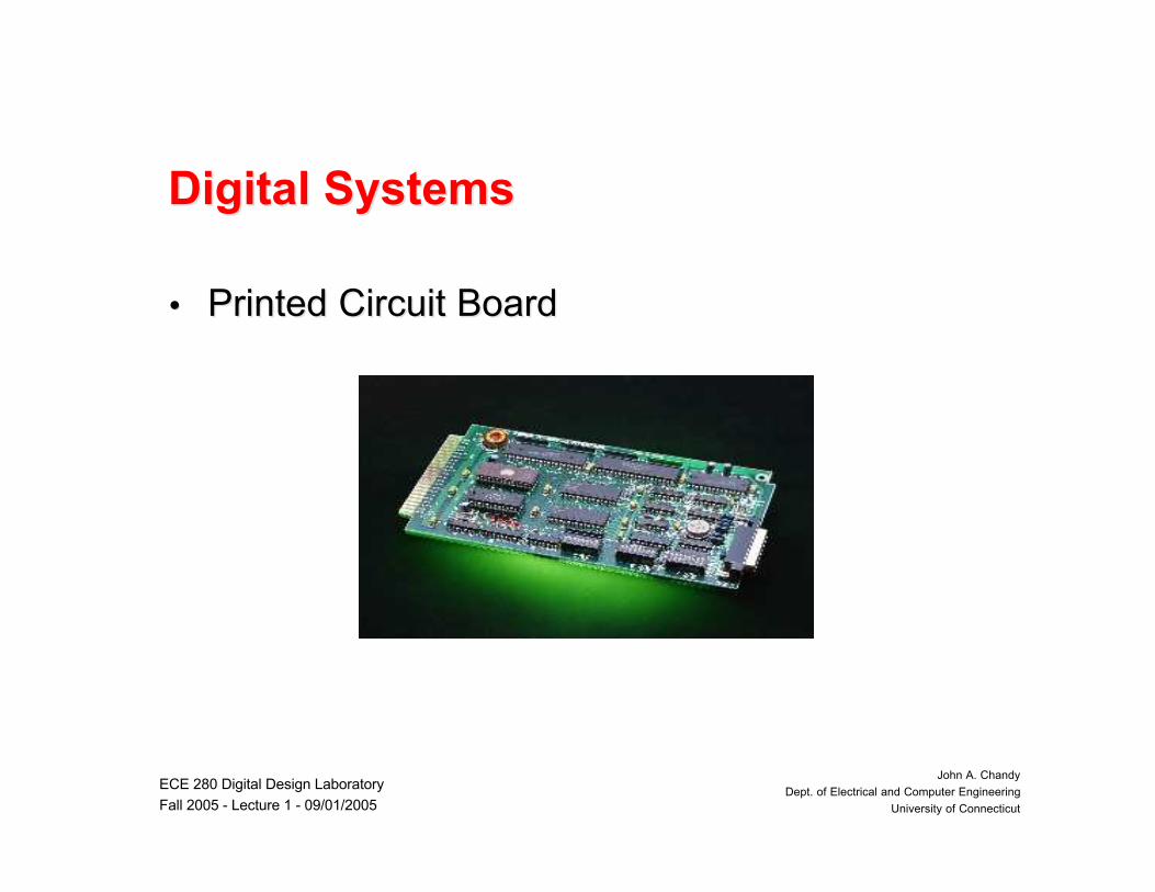
•• Printed Circuit BoardPrinted Circuit Board
ECE 280 Digital Design Laboratory
Fall 2005 - Lecture 1 - 09/01/2005
John A. Chandy
Dept. of Electrical and Computer Engineering
University of Connecticut
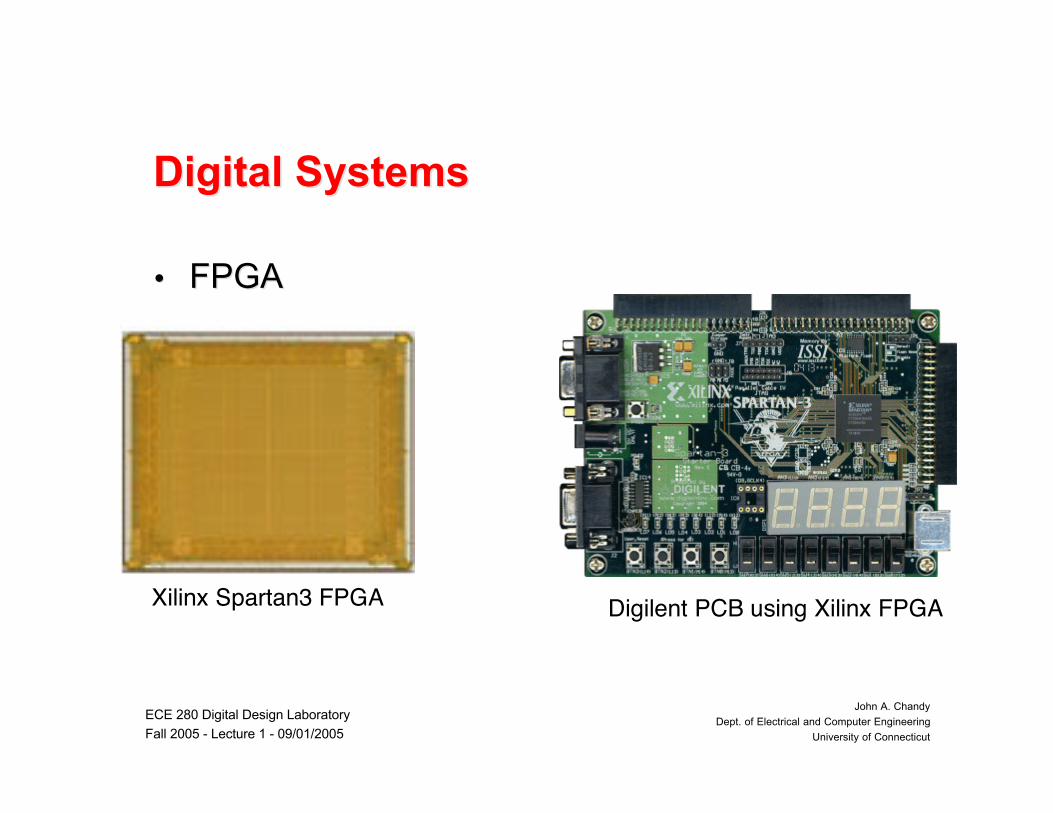
Digital SystemsDigital Systems
•• FPGAFPGA
Xilinx Spartan3 FPGA Digilent PCB using Xilinx FPGA
ECE 280 Digital Design Laboratory
Fall 2005 - Lecture 1 - 09/01/2005
John A. Chandy
Dept. of Electrical and Computer Engineering
University of Connecticut
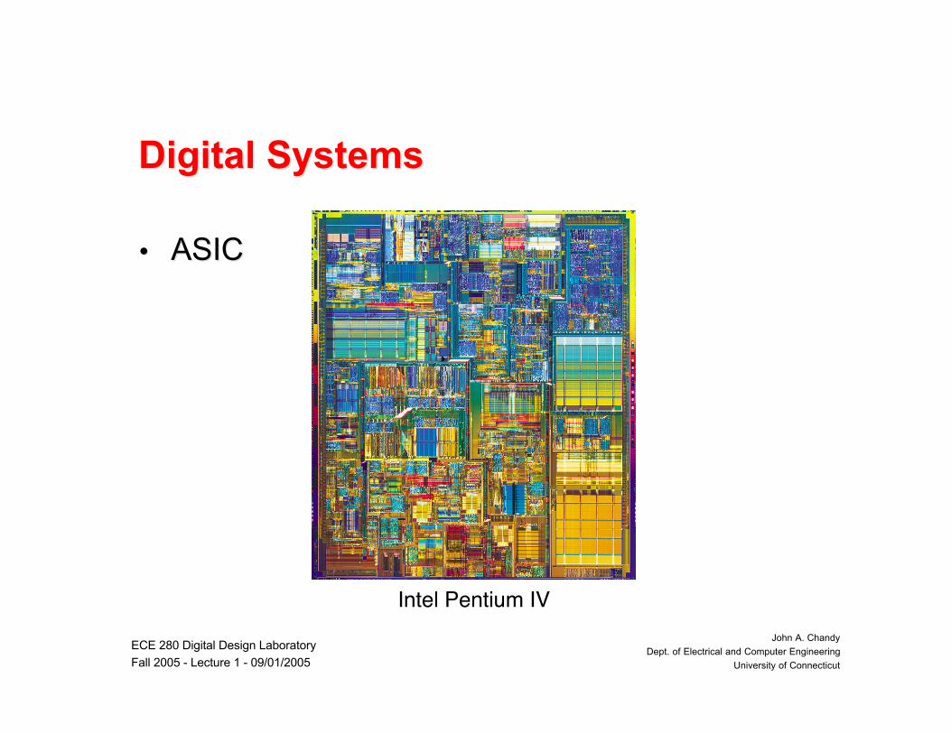
Digital SystemsDigital Systems
•• ASICASIC
Intel Pentium IV

ECE 280 Digital Design Laboratory
Fall 2005 - Lecture 1 - 09/01/2005
John A. Chandy
Dept. of Electrical and Computer Engineering
University of Connecticut
Digital SystemsDigital Systems•• SoCSoC
–– Reusable IPReusable IP
–– Embedded processor Embedded processor corescores
Philips Nexperia PNX831 Set Top Digital Video Chip
ECE 280 Digital Design Laboratory
Fall 2005 - Lecture 1 - 09/01/2005
John A. Chandy
Dept. of Electrical and Computer Engineering
University of Connecticut
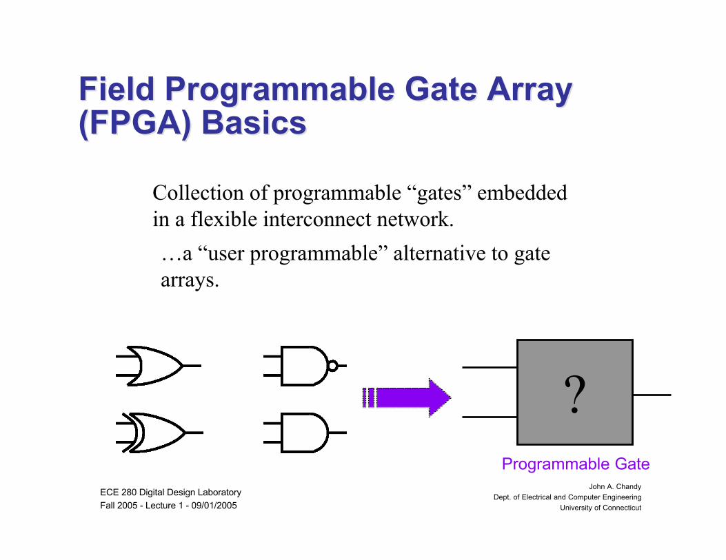
Field Programmable Gate ArrayField Programmable Gate Array(FPGA) Basics(FPGA) Basics
Collection of programmable “gates” embeddedin a flexible interconnect network.
…a “user programmable” alternative to gatearrays.
?Programmable Gate
ECE 280 Digital Design Laboratory
Fall 2005 - Lecture 1 - 09/01/2005
John A. Chandy
Dept. of Electrical and Computer Engineering
University of Connecticut
FPGA BasicsFPGA Basics
•• LUT for computeLUT for compute
•• FF for timing/retimingFF for timing/retiming
•• Switchable interconnectSwitchable interconnect
•• Everything we need to build fixed logicEverything we need to build fixed logiccircuitscircuits
–– latches can be built from gateslatches can be built from gates

ECE 280 Digital Design Laboratory
Fall 2005 - Lecture 1 - 09/01/2005
John A. Chandy
Dept. of Electrical and Computer Engineering
University of Connecticut
Look-Up Table (LUT)Look-Up Table (LUT)
In Out00 001 110 111 0
2-LUT
Mem
In1 In2
Out

ECE 280 Digital Design Laboratory
Fall 2005 - Lecture 1 - 09/01/2005
John A. Chandy
Dept. of Electrical and Computer Engineering
University of Connecticut
What is Digital Systems Design ?What is Digital Systems Design ?
•• Digital Systems Design is a process thatDigital Systems Design is a process that entails a entails asystematic development of an idea into an systematic development of an idea into an architecturearchitecturethat can be implemented digitally.that can be implemented digitally.
Specification
Architecture
Hardware
Design
Implement
Verify
ECE 280 Digital Design Laboratory
Fall 2005 - Lecture 1 - 09/01/2005
John A. Chandy
Dept. of Electrical and Computer Engineering
University of Connecticut
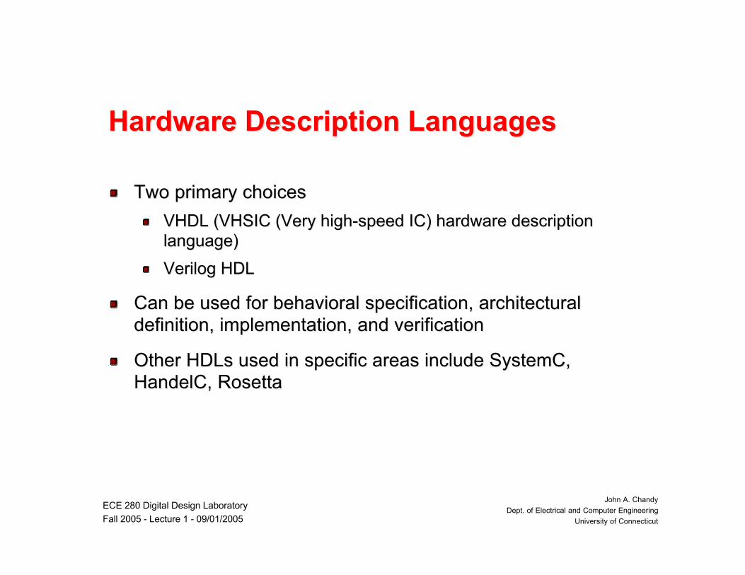
Hardware Description LanguagesHardware Description Languages
Two primary choicesTwo primary choices
VHDL (VHSIC (Very high-speed IC) hardware descriptionVHDL (VHSIC (Very high-speed IC) hardware descriptionlanguage)language)
Verilog HDLVerilog HDL
Can be used for behavioral specification, architecturalCan be used for behavioral specification, architecturaldefinition, implementation, and verificationdefinition, implementation, and verification
Other HDLs used in specific areas include SystemC,Other HDLs used in specific areas include SystemC,HandelC, RosettaHandelC, Rosetta
ECE 280 Digital Design Laboratory
Fall 2005 - Lecture 1 - 09/01/2005
John A. Chandy
Dept. of Electrical and Computer Engineering
University of Connecticut
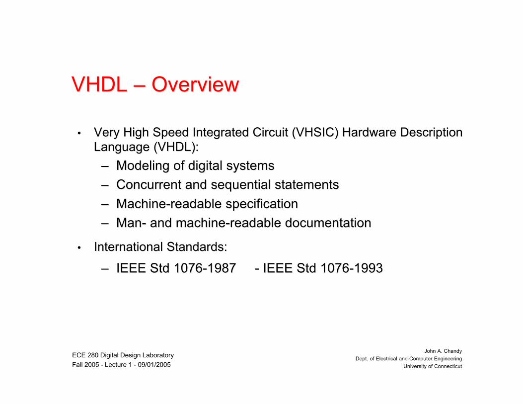
VHDL VHDL –– Overview Overview
•• Very High Speed Integrated Circuit (VHSIC) Hardware DescriptionVery High Speed Integrated Circuit (VHSIC) Hardware DescriptionLanguage (VHDL):Language (VHDL):
–– Modeling of digital systemsModeling of digital systems
–– Concurrent and sequential statementsConcurrent and sequential statements
–– Machine-readable specificationMachine-readable specification
–– Man- and machine-readable documentationMan- and machine-readable documentation
•• International Standards:International Standards:
–– IEEE Std 1076-1987 - IEEE Std 1076-1993IEEE Std 1076-1987 - IEEE Std 1076-1993

ECE 280 Digital Design Laboratory
Fall 2005 - Lecture 1 - 09/01/2005
John A. Chandy
Dept. of Electrical and Computer Engineering
University of Connecticut
Concepts of VHDLConcepts of VHDL
•• Execution of assignments:Execution of assignments:
–– Sequential:Sequential:•• Executed one after another, like in software programmingExecuted one after another, like in software programming
languages.languages.•• Can override the effects of previous statements.Can override the effects of previous statements.
–– Concurrent:Concurrent:•• Active continuously.Active continuously.•• The order of statements is not relevant.The order of statements is not relevant.•• Suited to model the parallelism of hardware.Suited to model the parallelism of hardware.

ECE 280 Digital Design Laboratory
Fall 2005 - Lecture 1 - 09/01/2005
John A. Chandy
Dept. of Electrical and Computer Engineering
University of Connecticut
Concepts of VHDLConcepts of VHDL
•• Methodologies:Methodologies:–– Abstraction:Abstraction: description of different parts of a system. description of different parts of a system.
•• On every abstraction level, only the essential information isOn every abstraction level, only the essential information isconsidered, nonessential information is left out.considered, nonessential information is left out.
–– ModularityModularity: split big functional blocks and to write a model for each: split big functional blocks and to write a model for eachpart.part.
–– Hierarchy:Hierarchy: build a design out of submodules. Each level of build a design out of submodules. Each level ofhierarchy may contain modules of different abstraction levels.hierarchy may contain modules of different abstraction levels.

ECE 280 Digital Design Laboratory
Fall 2005 - Lecture 1 - 09/01/2005
John A. Chandy
Dept. of Electrical and Computer Engineering
University of Connecticut
Digital Systems ModelingDigital Systems Modeling•• Gajski and Kuhn Y ChartGajski and Kuhn Y Chart
StructuralBehavioral/Functional
Physical/Geometry
Transistors
Circuit
Rectangles
Gates, FFsLogic
Logic
Cell, Module Plans
ALUs, RegistersRegister Transfer
Functional Block
Floor Plans
Hardware ModulesAlgorithms
Algorithmic
Clusters
Processor
Systems
Architectural
Physical Partitions(Adapted from RASSP Module 10, Slide 11)
Transfer Functions

ECE 280 Digital Design Laboratory
Fall 2005 - Lecture 1 - 09/01/2005
John A. Chandy
Dept. of Electrical and Computer Engineering
University of Connecticut
Abstraction levels in Digital DesignAbstraction levels in Digital Design
•• Behavioral level:Behavioral level:–– Functional description of the model is outlined.Functional description of the model is outlined.–– No system clock and signal transitions are asynchronousNo system clock and signal transitions are asynchronous
with respect to the switching time.with respect to the switching time.–– Simulation only,Simulation only, but but typically not synthesizable.typically not synthesizable.
ECE 280 Digital Design Laboratory
Fall 2005 - Lecture 1 - 09/01/2005
John A. Chandy
Dept. of Electrical and Computer Engineering
University of Connecticut
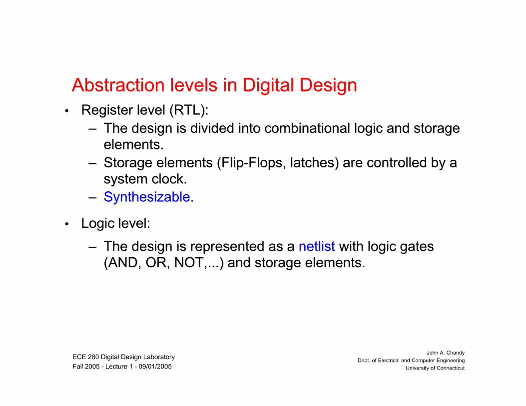
Abstraction levels in Digital DesignAbstraction levels in Digital Design•• Register level (RTL):Register level (RTL):
–– The design is divided into combinational logic and storageThe design is divided into combinational logic and storageelements.elements.
–– Storage elements (Flip-Flops, latches) are controlled by aStorage elements (Flip-Flops, latches) are controlled by asystem clock.system clock.
–– Synthesizable.Synthesizable.
•• Logic level:Logic level:
–– The design is represented as a The design is represented as a netlistnetlist with logic gates with logic gates(AND, OR, NOT,...) and storage elements.(AND, OR, NOT,...) and storage elements.
ECE 280 Digital Design Laboratory
Fall 2005 - Lecture 1 - 09/01/2005
John A. Chandy
Dept. of Electrical and Computer Engineering
University of Connecticut
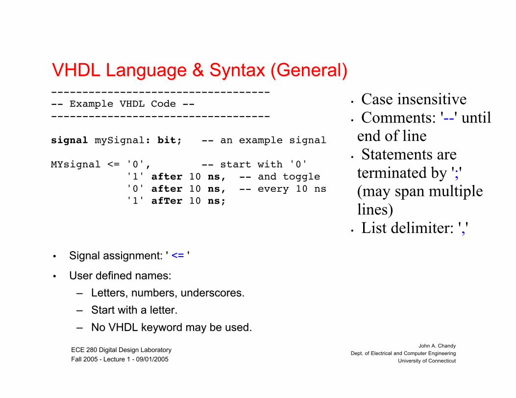
VHDL Language & Syntax (General)VHDL Language & Syntax (General)
•• Signal assignment: ' Signal assignment: ' <=<= ' '
•• User defined names:User defined names:
–– Letters, numbers, underscores.Letters, numbers, underscores.
–– Start with a letter.Start with a letter.
–– No VHDL keyword may be used.No VHDL keyword may be used.
------------------------------------- Example VHDL Code -------------------------------------
signal mySignal: bit; -- an example signal
MYsignal <= '0', -- start with '0' '1' after 10 ns, -- and toggle '0' after 10 ns, -- every 10 ns '1' afTer 10 ns;
• Case insensitive• Comments: '--' untilend of line
• Statements areterminated by ';'(may span multiplelines)
• List delimiter: ','

ECE 280 Digital Design Laboratory
Fall 2005 - Lecture 1 - 09/01/2005
John A. Chandy
Dept. of Electrical and Computer Engineering
University of Connecticut
VHDL Language & Syntax (Identifier)VHDL Language & Syntax (Identifier)•• Normal Identifier:Normal Identifier:
–– Letters, numbers, underscoresLetters, numbers, underscores
–– Uppercase and lowercase letters areUppercase and lowercase letters areequivalent when used in identifiers (Caseequivalent when used in identifiers (Caseinsensitive)insensitive)
–– The first character must be a letter.The first character must be a letter.
–– The last character cannot be an underscore.The last character cannot be an underscore.
–– No two consecutive underscoresNo two consecutive underscores..
–– VHDL reserved words may not be used asVHDL reserved words may not be used asidentifiers.identifiers.
•• Extended Identifier (VHDL93)Extended Identifier (VHDL93)
–– Enclosed in back slashesEnclosed in back slashes
–– Case sensitiveCase sensitive
–– Graphical characters allowedGraphical characters allowed
–– May contain spaced and consecutiveMay contain spaced and consecutiveunderscores.underscores.
–– VHDL keywords allowedVHDL keywords allowed
MySignal_23 -- normal identifierrdy, RDY, Rdy -- identical identifiersvector_&_vector -- X : special characterlast of Zout -- X : white spacesidle__state -- X : consecutive underscores24th_signal -- X : begins with a numeralopen, register -- X : VHDL keywords
\mySignal_23\ -- extended identifier\rdy\, \RDY\, \Rdy\ -- different identifiers\vector_&_vector\ -- legal\last of Zout\ -- legal\idle__state\ -- legal\24th_signal\ -- legal\open\, \register\ -- legal

ECE 280 Digital Design Laboratory
Fall 2005 - Lecture 1 - 09/01/2005
John A. Chandy
Dept. of Electrical and Computer Engineering
University of Connecticut
Legal and Illegal Identifiers_ Legal Identifiers:
– Uconn_huskies– ECE_252– Sel6B
_ Illegal Identifiers:– _time_is_9am -- an identifier must start with a
letter.– 8thsemester -- an identifier must start with a letter.– Homework#1 -- letter, digits, and underscore only.– final_ _example -- two underscore in succession not
allowed– Entity -- keyword cannot be used as
identifier– Time_out_ -- last character cannot be an underscore.

ECE 280 Digital Design Laboratory
Fall 2005 - Lecture 1 - 09/01/2005
John A. Chandy
Dept. of Electrical and Computer Engineering
University of Connecticut
VHDL Reserved WordsVHDL Reserved Words
xorxorsignalsignalisis
xnorxnorsharedsharedoutoutinoutinoutconstantconstant
withwithseverityseverityothersothersinertialinertialconfigurationconfiguration
whilewhileselectselectororinincomponentcomponent
whenwhenrorroropenopenimpureimpurecasecase
waitwaitrolrolononififbusbus
variablevariablereturnreturnofofguardedguardedbufferbuffer
useusereportreportnullnullgroupgroupbodybody
untiluntilremremnotnotgenericgenericblockblock
unitsunitsrejectrejectnornorgenerategeneratebeginbegin
unaffectedunaffectedregisterregisternextnextfunctionfunctionattributeattribute
typetyperecordrecordnewnewforforassertassert
transporttransportrangerangenandnandfilefilearrayarray
totopurepuremodmodexitexitarchitecturearchitecture
thenthenprotectedprotectedmapmapentityentityandand
subtypesubtypeprocessprocesslooploopendendallall
srlsrlprocedureprocedureliteralliteralelsifelsifaliasalias
srasrapostponedpostponedlinkagelinkageelseelseafterafter
sllsllportportlibrarylibrarydowntodowntoaccessaccess
slaslapackagepackagelabellabeldisconnectdisconnectabsabs
ECE 280 Digital Design Laboratory
Fall 2005 - Lecture 1 - 09/01/2005
John A. Chandy
Dept. of Electrical and Computer Engineering
University of Connecticut
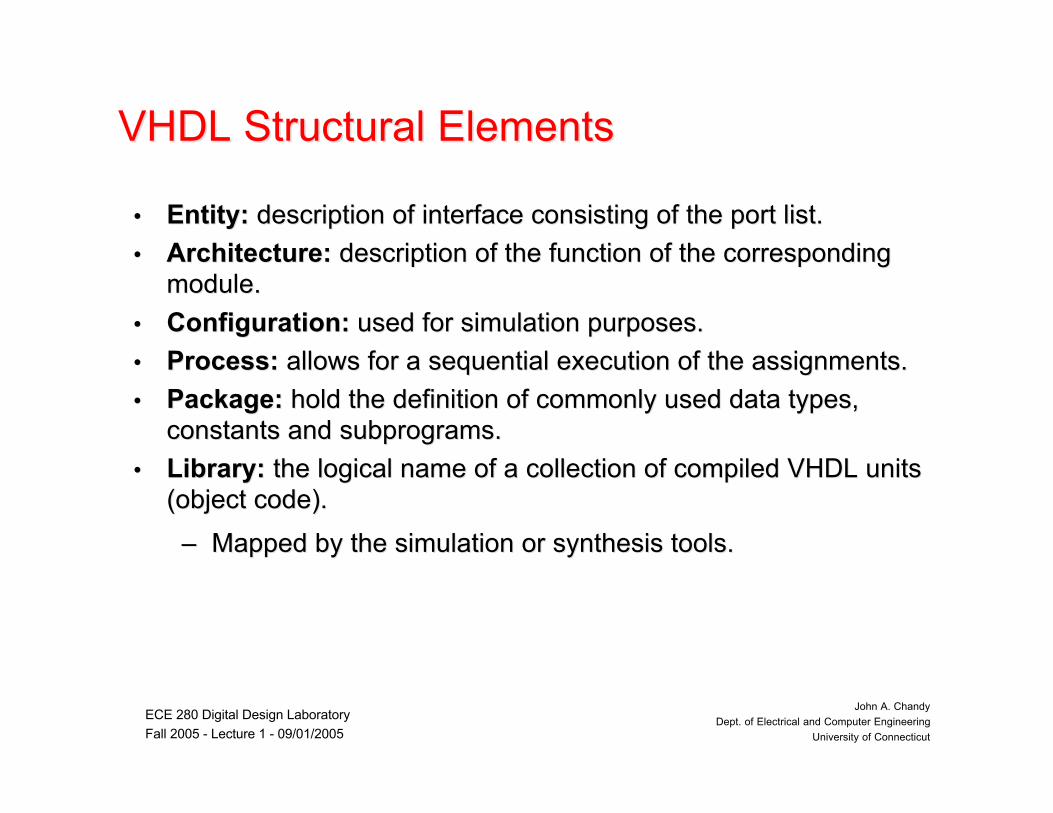
VHDL Structural ElementsVHDL Structural Elements
•• Entity:Entity: description of interface consisting of the port list. description of interface consisting of the port list.
•• Architecture: Architecture: description of the function of the correspondingdescription of the function of the correspondingmodule.module.
•• Configuration:Configuration: used for simulation purposes. used for simulation purposes.
•• Process:Process: allows for a sequential execution of the assignments. allows for a sequential execution of the assignments.
•• Package: Package: hold the definition of commonly used data types,hold the definition of commonly used data types,constants and subprograms.constants and subprograms.
•• Library:Library: the logical name of a collection of compiled VHDL units the logical name of a collection of compiled VHDL units(object code).(object code).
–– Mapped by the simulation or synthesis tools.Mapped by the simulation or synthesis tools.

ECE 280 Digital Design Laboratory
Fall 2005 - Lecture 1 - 09/01/2005
John A. Chandy
Dept. of Electrical and Computer Engineering
University of Connecticut
Entity statementEntity statement
•• InterfaceInterface description description
•• Linking via port signalsLinking via port signals
–– Data typesData types
–– Signal widthSignal width
–– Signal directionSignal direction
•• Port clause identifiesPort clause identifiesports used by "entity" toports used by "entity" tocommunicates with itscommunicates with itsenvironment.environment.
entity HALFADDER isport( A, B: in bit; SUM, CARRY: out bit);end HALFADDER;
entity ADDER is port( A, B: in integer range 0 to 3; SUM: out integer range 0 to 3; CARRY: out bit );end entity ADDER;

ECE 280 Digital Design Laboratory
Fall 2005 - Lecture 1 - 09/01/2005
John A. Chandy
Dept. of Electrical and Computer Engineering
University of Connecticut
Entity Port Modes
in:signal values are read-only
out:signal values are write-onlymultiple drivers
buffer:comparable to outsignal values may be read as wellonly 1 driver
inout:bidirectional port
ECE 280 Digital Design Laboratory
Fall 2005 - Lecture 1 - 09/01/2005
John A. Chandy
Dept. of Electrical and Computer Engineering
University of Connecticut
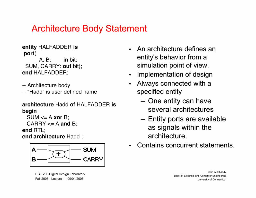
Architecture Body StatementArchitecture Body Statement
•• An architecture defines anAn architecture defines anentity's behavior from aentity's behavior from asimulation point of view.simulation point of view.
•• Implementation of designImplementation of design•• Always connected with aAlways connected with a
specified entityspecified entity
–– One entity can haveOne entity can haveseveral architecturesseveral architectures
–– Entity ports are availableEntity ports are availableas signals within theas signals within thearchitecture.architecture.
•• Contains concurrent statements.Contains concurrent statements.
entity HALFADDER is port( A, B: in bit; SUM, CARRY: out bit);end HALFADDER;
-- Architecture body-- "Hadd" is user defined name
architecture Hadd of HALFADDER isbegin SUM <= A xor B; CARRY <= A and B;end RTL;end architecture Hadd ;

ECE 280 Digital Design Laboratory
Fall 2005 - Lecture 1 - 09/01/2005
John A. Chandy
Dept. of Electrical and Computer Engineering
University of Connecticut
Architecture Body StructureArchitecture Body Structure•• Declarative part:Declarative part:
–– data typesdata types–– constantsconstants–– additional signals ("actual"additional signals ("actual"
signals)signals)–– componentscomponents–– ......
•• Statement part (after 'begin'):Statement part (after 'begin'):–– signal assignmentssignal assignments–– processesprocesses–– component instantiationscomponent instantiations–– concurrent statements canconcurrent statements can
be placed within thebe placed within thestatement part..statement part..
-- architecture Bodyarchitecture EXAMPLE of STRUCTURE is-- Declarative part subtype DIGIT is integer range 0 to 9; constant BASE: integer := 10; signal DIGIT_A, DIGIT_B: DIGIT; signal CARRY: DIGIT;
begin-- Statement part DIGIT_A <= 3; SUM <= DIGIT_A + DIGIT_B; DIGIT_B <= 7; CARRY <= 0 when SUM < BASE else 1;
end EXAMPLE ;
ECE 280 Digital Design Laboratory
Fall 2005 - Lecture 1 - 09/01/2005
John A. Chandy
Dept. of Electrical and Computer Engineering
University of Connecticut
Data ObjectsData Objects
•• Data objects hold a value of specified type. They belongData objects hold a value of specified type. They belongto one of three classes:to one of three classes:
–– ConstantsConstants
–– SignalsSignals
–– VariablesVariables
•• Must be declared before they are usedMust be declared before they are used
• Signals are typically used to model wires and flip-flops,while constants and variables are typically used to modelthe behavior of the circuit.

ECE 280 Digital Design Laboratory
Fall 2005 - Lecture 1 - 09/01/2005
John A. Chandy
Dept. of Electrical and Computer Engineering
University of Connecticut
SignalsSignals
• Signal data objects represent the logic signals orwires in a circuit. Signals can also represent thestate of a memory
• There are three places in which signals can bedeclared in a VHDL code
– In an entity declaration
– In the declarative part of an architecture
– In the declarative part of a package.
ECE 280 Digital Design Laboratory
Fall 2005 - Lecture 1 - 09/01/2005
John A. Chandy
Dept. of Electrical and Computer Engineering
University of Connecticut
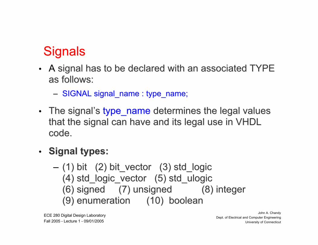
SignalsSignals•• AA signal has to be signal has to be declared with an associated TYPE declared with an associated TYPE
as follows:as follows:
–– SIGNAL signal_name : type_name;SIGNAL signal_name : type_name;
•• The signalThe signal’’ss type_name type_name determines the legal values determines the legal valuesthat the signal can have and its legal use in VHDLthat the signal can have and its legal use in VHDLcode.code.
•• Signal types:Signal types:
–– (1) bit (2) bit_vector (3) std_logic(1) bit (2) bit_vector (3) std_logic(4) std_logic_vector (5) std_ulogic(4) std_logic_vector (5) std_ulogic(6) signed (7) unsigned (8) integer(6) signed (7) unsigned (8) integer(9) enumeration (10) boolean(9) enumeration (10) boolean

ECE 280 Digital Design Laboratory
Fall 2005 - Lecture 1 - 09/01/2005
John A. Chandy
Dept. of Electrical and Computer Engineering
University of Connecticut
Logic OperatorsLogic Operators
•• and, or, xor, xnor, nand, nor, notand, or, xor, xnor, nand, nor, not
•• Example:Example:
–– Z <= A Z <= A andand B B andand C; C;
–– Z <= ( Z <= (notnot A A andand B) B) oror (A (A andand notnot B); B);
ECE 280 Digital Design Laboratory
Fall 2005 - Lecture 1 - 09/01/2005
John A. Chandy
Dept. of Electrical and Computer Engineering
University of Connecticut
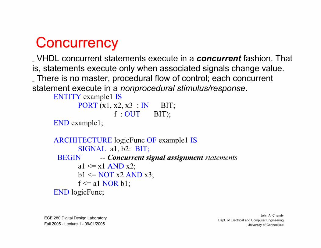
ConcurrencyConcurrency_ VHDL concurrent statements execute in a concurrent fashion. Thatis, statements execute only when associated signals change value._ There is no master, procedural flow of control; each concurrentstatement execute in a nonprocedural stimulus/response.
ENTITY example1 ISPORT (x1, x2, x3 : IN BIT;
f : OUT BIT);END example1;
ARCHITECTURE logicFunc OF example1 ISSIGNAL a1, b2: BIT;
BEGIN -- Concurrent signal assignment statementsa1 <= x1 AND x2;
b1 <= NOT x2 AND x3; f <= a1 NOR b1;END logicFunc;

ECE 280 Digital Design Laboratory
Fall 2005 - Lecture 1 - 09/01/2005
John A. Chandy
Dept. of Electrical and Computer Engineering
University of Connecticut
Process StatementProcess Statement
•• PROCESSPROCESS statement:statement:–– basic building block for behavioral modelingbasic building block for behavioral modeling of of
digital systems.digital systems.–– concurrent shell in which a concurrent shell in which a sequential statementsequential statement
can be executed.can be executed.–– appears inside an architecture body, and itappears inside an architecture body, and it
encloses other statements within it.encloses other statements within it.–– IF, CASEIF, CASE, and , and LOOPLOOP statements can appear statements can appear
only inside a process.only inside a process.–– All statements with a process are All statements with a process are executedexecuted
sequentiallysequentially when the process becomes active.when the process becomes active.

ECE 280 Digital Design Laboratory
Fall 2005 - Lecture 1 - 09/01/2005
John A. Chandy
Dept. of Electrical and Computer Engineering
University of Connecticut
Process Statement FormatProcess Statement Format
[Process_label] : [Process_label] : PROCESSPROCESS [(sensitivity_list)] [(sensitivity_list)]
Process_declarative_region Process_declarative_region
BEGINBEGIN
process_statement_region process_statement_region
END PROCESSEND PROCESS [Process_label] [Process_label]
•• The keyword The keyword PROCESSPROCESS in the first line is the beginning delimiter of in the first line is the beginning delimiter ofthe process. The optional label allows for a user_defined name forthe process. The optional label allows for a user_defined name forthe process.the process.
•• The The END PROCESSEND PROCESS is the ending delimiter of the process statement. is the ending delimiter of the process statement.If the label is included in the If the label is included in the END PROCESSEND PROCESS clause, it must match clause, it must matchthe process label.the process label.

ECE 280 Digital Design Laboratory
Fall 2005 - Lecture 1 - 09/01/2005
John A. Chandy
Dept. of Electrical and Computer Engineering
University of Connecticut
Process Statement Sensitivity ListProcess Statement Sensitivity List•• The process statement may include an optional The process statement may include an optional sensitivity sensitivity listlist..
A sensitivity list contains the signals that trigger the process.A sensitivity list contains the signals that trigger the process.
•• The process statement begins to execute if any of the signalsThe process statement begins to execute if any of the signalssensitivity list contains an event.sensitivity list contains an event.
•• Once activated by a Once activated by a sensitivity list eventsensitivity list event, the process, the processstatement executes statements in a sequential manner.statement executes statements in a sequential manner.
•• Upon reaching the end of the process execution suspendsUpon reaching the end of the process execution suspendsuntil another event occurs from the sensitivity list.until another event occurs from the sensitivity list.
ECE 280 Digital Design Laboratory
Fall 2005 - Lecture 1 - 09/01/2005
John A. Chandy
Dept. of Electrical and Computer Engineering
University of Connecticut
VariablesVariables
•• A A variablevariable, unlike a SIGNAL, does not necessarily, unlike a SIGNAL, does not necessarilyrepresent a wire in a circuit.represent a wire in a circuit.
•• Variables can be Variables can be used in sequential areas onlyused in sequential areas only- i.e.- i.e.processes and subprograms.processes and subprograms.
•• The scope of a variable is the process or theThe scope of a variable is the process or thesubprogram.subprogram.
•• A variable in a subprogram does not retain its valueA variable in a subprogram does not retain its valuebetween calls.between calls.
•• Variable assignment is immediate, not scheduled.Variable assignment is immediate, not scheduled.

ECE 280 Digital Design Laboratory
Fall 2005 - Lecture 1 - 09/01/2005
John A. Chandy
Dept. of Electrical and Computer Engineering
University of Connecticut
Modeling Modeling of Flip-Flopsof Flip-Flops
•• D Flip-flop controlled by aD Flip-flop controlled by aclock pulse edge.clock pulse edge.
•• If an event occurs at theIf an event occurs at theclock signal and this eventclock signal and this eventhas the value ONE, thehas the value ONE, thevalue of the pin D will bevalue of the pin D will betransferred to the pin Qtransferred to the pin Q..
Library IEEE;use IEEE.Std_Logic_1164.all;
entity FLOP is port (D, CLK : in std_logic; Q : out std_logic);end FLOP;
architecture A of FLOP isbegin process(CLK) begin if CLK’event and CLK=‘1’; Q <= D;
end if; end process;end A;

ECE 280 Digital Design Laboratory
Fall 2005 - Lecture 1 - 09/01/2005
John A. Chandy
Dept. of Electrical and Computer Engineering
University of Connecticut
Lab 1Lab 1•• Design a digital system that can display aDesign a digital system that can display a
counter on a set of 7-segment LCDcounter on a set of 7-segment LCDdisplaysdisplays
•• Switches control hex or decimal displaySwitches control hex or decimal display

ECE 280 Digital Design Laboratory
Fall 2005 - Lecture 1 - 09/01/2005
John A. Chandy
Dept. of Electrical and Computer Engineering
University of Connecticut
Lab1Lab1
•• 1 millisecond pulse1 millisecond pulse