raspberry pi basics - school of engineeringengr.uconn.edu/~song/classes/nes/rpi.pdf · raspberry pi...
TRANSCRIPT

RASPBERRY PI BASICS

System on Chip (SoC)
• What is System on Chip?– A complex IC that integrates the major functional elements
into a single chip or chipset. • programmable processor
• on-chip memory
• accelerating function hardware (e.g. GPU)
• both hardware and software
• analog components
• Benefits of SoC– Reduce overall system cost
– Increase performance
– Lower power consumption
– Reduce size

SoC in Raspberry Pi: Broadcom
BCM2835 SoC Multimedia processor• CPU
– ARM 1176JZF-S (armv6k) 700MHz
– RISC Architecture and low power draw
– Not compatible with traditional PC software
• GPU– Broadcom Video IV
– Specialized graphical instruction sets
• RAM– 512MB (Model B rev.2)
– 256 MB (Model A, Model B rev.1)

SoC in Raspberry Pi:
Broadcom BCM2835 SoC
BCM2835 SoC (right) and Samsung K4P2G324ED Mobile DRAM (left)

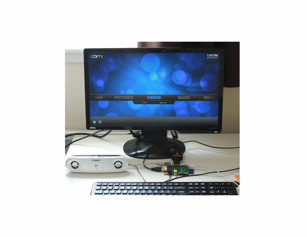
Connecting a Display and Audio
• HDMI– Digital signal
– Video and audio signal
– DVI cannot carry audio signal
– Up to 1920x1200 resolution
• Composite RCA– Analog signal
– 480i, 576i resolution
• 3.5mm jack

RPi Remote Connections
http://pihw.wordpress.com/guides/direct-network-connection/

Universal Serial Bus
• Two USB 2.0 ports in RPi
• Buy a powered USB hub
Passive models are cheaper and smaller, but lack the ability to run current-hungry devices like CD drives and external hard drives.

Storage: Secure Digital (SD)• Form factor
– SD, Mini SD, Micro SD
• Types of Card
– SDSC (SD): 1MB to 2GB
– SDHC: 4GB to 32 GB
– SDXD up to 2TB
The card should be at least 2GB in capacity to store all the required files

Storage: Continue
SD Formatter:
https://www.sdcard.org/downloads/formatter_4/
How to mount USB flash drive from
command line:
http://linuxcommando.blogspot.co.uk/2007/12/how-to-mount-usb-flash-drive-from.html

Networking
Ethernet (IEEE 802.3)
USB Ethernet Converter
Wi-Fi Adapter
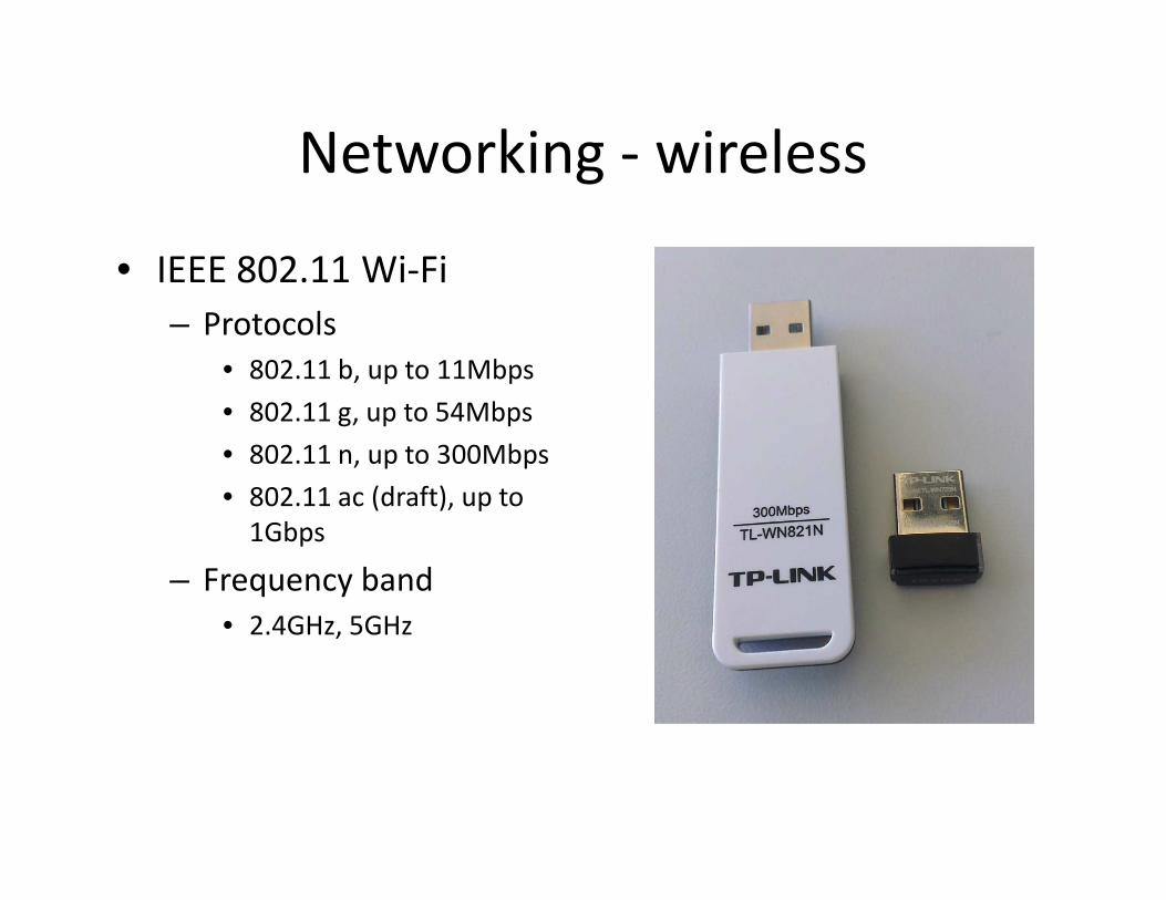
Networking - wireless
• IEEE 802.11 Wi-Fi
– Protocols
• 802.11 b, up to 11Mbps
• 802.11 g, up to 54Mbps
• 802.11 n, up to 300Mbps
• 802.11 ac (draft), up to
1Gbps
– Frequency band
• 2.4GHz, 5GHz

Low Speed Peripherals
• General Purpose
Input/Output (GPIO)
– Pins can be configured to
be input/output
– Reading from various
environmental sensors
• Ex: IR, video,
temperature, 3-axis
orientation, acceleration
– Writing output to dc
motors, LEDs for status.

Power Consumption
• microUSB power connector
– 2.5W (model A)
– 3.5W (model B)
• Powered USB hub
– To provide more power for USB peripherals

Useful links
• Raspberry Pi official website
– http://www.raspberrypi.org/
• Raspberry Pi wiki
– http://elinux.org/RaspberryPiBoard
• Raspberry Pi verified peripherals
– http://elinux.org/RPi_VerifiedPeripherals
• The MagPi
– http://www.themagpi.com
• Raspberry Pi on Adafruit Learning System:
– http://learn.adafruit.com/category/learn-raspberry-pi

• 1. Download the Raspberry Pi operating system– Linux releases compatible with the Pi:
http://www.raspberrypi.org/downloads
– The recommended OS is Raspbian:
http://downloads.raspberrypi.org/raspbian_latest
• 2. Unzip the file that you just downloaded– Right click on the file and choose “Extract all”.
– Follow the instructions—you will end up with a file ending in .img
Raspberry Pi Setup


• 3. Download the Win32DiskImager software
– a) Download win32diskimager-binary.zip
(currently version 0.6) from:
https://launchpad.net/win32-image-
writer/+download
– b) Unzip it in the same way you did the Raspbian
.zip file
– c) You now have a new folder called
win32diskimager-binary

• 4. Writing Raspbian to the SD card– a) Plug your SD card into your PC
– b) In the folder you made in step 3(b), run the file named Win32DiskImager.exe
– c) If the SD card (Device) you are using isn’t found automatically then click on the drop down box and select it
– d) In the Image File box, choose the Raspbian .img file that you downloaded
– e) Click Write
– f) After a few minutes you will have an SD card that you can use in your Raspberry Pi

• 5. Booting your Raspberry Pi for the first time
– On first boot you will come to the Raspi-config window
– Change settings such as timezone and locale if you want
– Finally, select the second choice: expand_rootfs and say ‘yes’ to a reboot
– The Raspberry Pi will reboot and you will see raspberrypilogin:
• Username: pi, password: raspberry
– Start the desktop by typing: startx
– The desktop environment is known as the Lightweight X11 Desktop Environment (LXDE)


Re-mapping Keyboard:
• sudo vi /etc/default/keyboard
XKBLAYOUT=”gb”
Change “gb” to “us”
• (This assumes you want a us mapping, if not
replace the gb with the two letter code for
your country)

Install and Start SSH
• Update apt-get package index files:
– sudo apt-get update
• Install SSH:
– sudo apt-get install ssh
• Start SSH server:
– sudo /etc/init.d/ssh start
• To start the SSH server every time the Pi boots up:
– sudo update-rc.d ssh defaults

• SSH client for Windows:
– PuTTY
– http://www.putty.org/
• SSH Secure File Transfer
– http://www.utexas.edu/learn/upload/ssh_client.h
tml


Install Java
• 1. JDK 8 (with JavaFX) for ARM Early Access
http://jdk8.java.net/fxarmpreview/
– Download from Raspberry pi
– Download from your own PC and copy it (scp) to
Raspberry pi
• Extract the JDK tar.gz file
– tar –zxvf fileToExtract.tar.gz
– You will get a folder “jdk1.8.0”

Set Java PATH
• If you put the folder “jdk1.8.0” in the home directory (i.e. /home/pi), you will see the java executables (e.g. javac, java, appletviewer) in the directory: /home/pi/jdk1.8.0/bin
• open /etc/profileadd:
PATH=$PATH:/home/pi/jdk1.8.0/bin export PATH
• Reboot:
sudo reboot

Linux System Administration
29
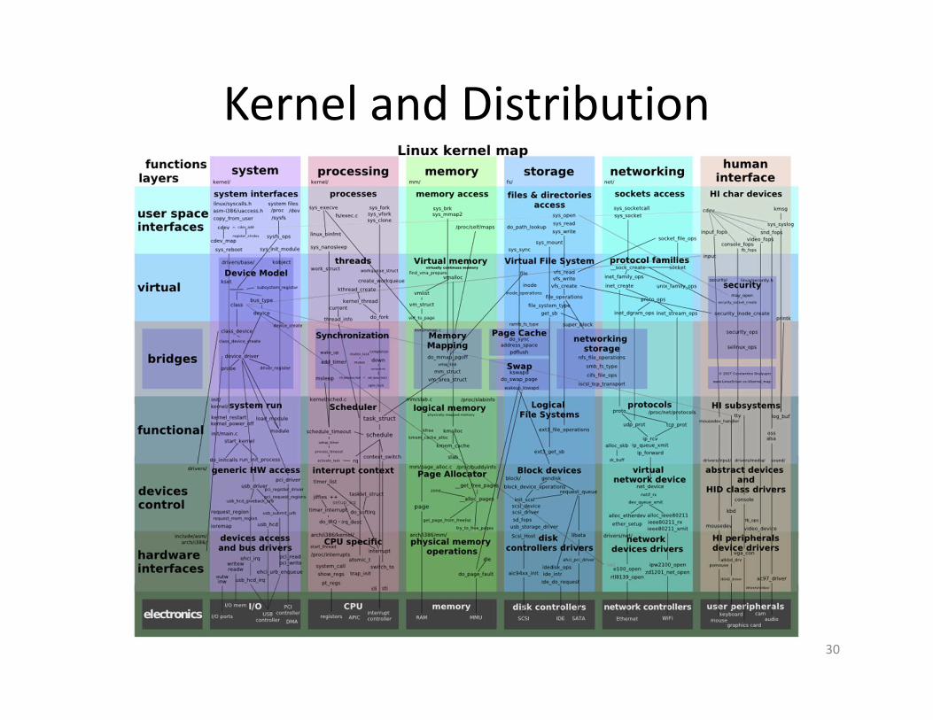
Kernel and Distribution
30

Kernel and Distribution
31
Although only the kernel itself is rightly
called Linux, the term is often used to
refer to a collection of different open-
source projects from a variety of
companies. These collections come
together to form different flavors of
Linux, known as distributions.
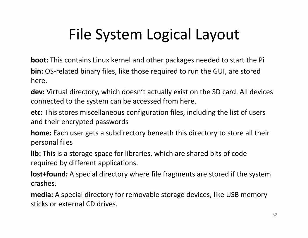
File System Logical Layout
boot: This contains Linux kernel and other packages needed to start the Pi
bin: OS-related binary files, like those required to run the GUI, are stored
here.
dev: Virtual directory, which doesn’t actually exist on the SD card. All devices
connected to the system can be accessed from here.
etc: This stores miscellaneous configuration files, including the list of users
and their encrypted passwords
home: Each user gets a subdirectory beneath this directory to store all their
personal files
lib: This is a storage space for libraries, which are shared bits of code
required by different applications.
lost+found: A special directory where file fragments are stored if the system
crashes.
media: A special directory for removable storage devices, like USB memory
sticks or external CD drives.
32

File System Logical Layout
mnt: This folder is used to manually mount storage devices, such as external hard drives.
opt: This stores optional software that is not part of the OS itself. If you install new software to your Pi, it will usually go here.
proc: Another virtual directory, containing information about running programs which are known in Linux as processes.
selinux: Files related to Security Enhanced Linux, a suite of security utilites originally developed by the US National Security Agency.
sbin: Stores special binary files, primarily used by the root account for system maintenance.
sys: This directory is where special OS files are stored.
tmp: Temporary files are stored here automatically.
usr: This directory provides storage for user accessible programs.
var: This is virtual directory that programs use to store changing values or variables.
33
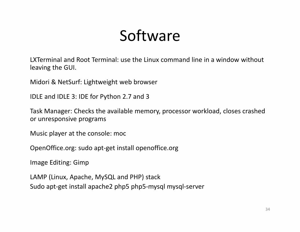
Software
LXTerminal and Root Terminal: use the Linux command line in a window without leaving the GUI.
Midori & NetSurf: Lightweight web browser
IDLE and IDLE 3: IDE for Python 2.7 and 3
Task Manager: Checks the available memory, processor workload, closes crashed or unresponsive programs
Music player at the console: moc
OpenOffice.org: sudo apt-get install openoffice.org
Image Editing: Gimp
LAMP (Linux, Apache, MySQL and PHP) stack
Sudo apt-get install apache2 php5 php5-mysql mysql-server
34

Installing, Uninstalling and Updating Software
• Package manager in Debian: apt• GUI for apt, Synaptic Package Manager doesn’t work well on Pi due to the
lack of memory
• Make sure that the apt cache is up to date: • apt-get update
• Finding software: • apt-cache search emacs
• Installing software and dependencies: • sudo apt-get install emacs
• Uninstalling software: • sudo apt-get remove emacs
• sudo apt-get purge emacs (removes everything including configurations)
• Upgrading software:• Sudo apt-get upgrade
• Sudo apt-get install emacs
35
Troubleshooting
36
Keyboard and Mouse Diagnostics
Power Diagnostics
Display Diagnostics
Network Diagnostics
Emergency Kernel
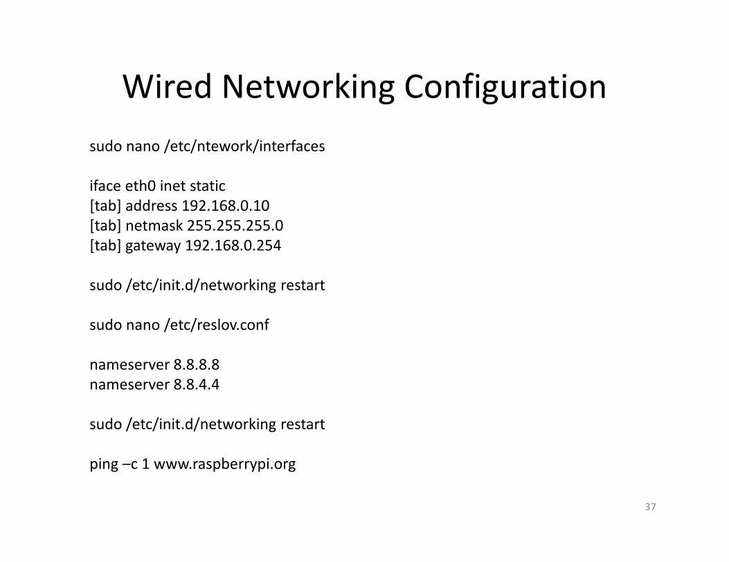
Wired Networking Configuration
37
sudo nano /etc/ntework/interfaces
iface eth0 inet static
[tab] address 192.168.0.10
[tab] netmask 255.255.255.0
[tab] gateway 192.168.0.254
sudo /etc/init.d/networking restart
sudo nano /etc/reslov.conf
nameserver 8.8.8.8
nameserver 8.8.4.4
sudo /etc/init.d/networking restart
ping –c 1 www.raspberrypi.org

Wireless Networking Configuration
38
• USB Wi-Fi adapters are very power-hungry. Connect a powered USB
hub to the Pi, and then insert the Wi-Fi adapter into that.
• Print out the entire kernel ring buffer and find out the company that
makes the actual chip: mesg | grep ^usb
Atmel-firmware
Firmware-atheros
Firmware-brcm80211
Firmeware-intelwimax
Firmware-ipw2x00
Firmware-iwlwifi
Firmware-ralink
Firmware-realteck
Zd1211-firmware
• Check the current status of the network: iwconfig
Configurating the Raspberry Pi
39
RPi doesn’t have a BIOS menu. It relies on
text files containing configuration strings that
are loaded by the chip when powers on.
• Hardware settings: config.txt
• Memory Partitioning: start.elf
• Software Settings: cmdline.txt

References for Python
Beginner’s Guide to Python
http://wiki.python.org/moin/BeginnersGuide
A free, interactive tutorial
http://www.learnpython.org
Learn Python the Hard Way (Shavian Publishing, 2012)
Dive Into Python 3 (APRESS, 2009)
40

General Purpose Input/Output
(GPIO)
41

• General Purpose Input/Output (GPIO) is a
generic pin on a chip whose behavior can be
controlled by the user at run time.
42

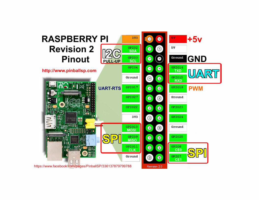
• The GPIO connector has a number of different types of connection:
– True GPIO (General Purpose Input Output) pins that you can use to turn LEDs on and off etc.
– I2C interface pins that allow you to connect hardware modules with just two control pins
– SPI interface with SPI devices, a similar concept to I2C but uses a different standard
– Serial Rx and Tx pins for communication with serial peripherals
43

• GPIO pins can be used as both digital outputs and digital inputs.
• Output: turn a particular pin HIGH or LOW.
– Setting it HIGH sets it to 3.3V; setting it LOW sets it to 0V.
• Input: detect the pin being at HIGH or LOW
– we can connect switches and simple sensors to a pin and check whether it is open or closed (that is, activated or not)
44

All the pins have 3.3V logic levels and are not 5V-safe so the output levels are
0-3.3V and the inputs should not be higher than 3.3V. 45
To use the pin numbers from the ribbon cable board:
GPIO.setmode(GPIO.BCM)
To use the pin numbers on raspberry pi board
GPIO.setmode(GPIO.BOARD)

Electronic Equipment
• Breadboard– Components in the same row are connected together without wires
• Jumper Wires– Try to use different colors to differentiate different purposes
• Resistors
• Push-Buttons
• LEDs
46

47

GPIO setup on Raspberry Pi
• Install Python 2 library Rpi.GPIO.
– A library that will let us control the GPIO pins.
• https://pypi.python.org/pypi/RPi.GPIO
• Install commands:
sudo apt-get update
sudo apt-get install python-dev
sudo apt-get install python-rpi.gpio
48
GPIO as Output
• Experiment 1: Controlling LED
– LED
– Breadboard
– Jumper wire
49

Breadboard
• Build circuit easily without soldering
50

Use Cobbler kit to extend the GPIO to
breadboard
51

Light-emitting diode (LED)
• Current flows from the anode to cathode.
– Anode: longer pin
– Cathode: shorter pin
• Use a multimeter to test the polarity
– Check resistance
– In both directions.
52

Multimeter
53

Task 1: Turn LED on for 2 seconds and
off for 1 second, loop forever
• In this example, we control the LED
by controlling the voltage at the
anode (+).
54
Code for task 1
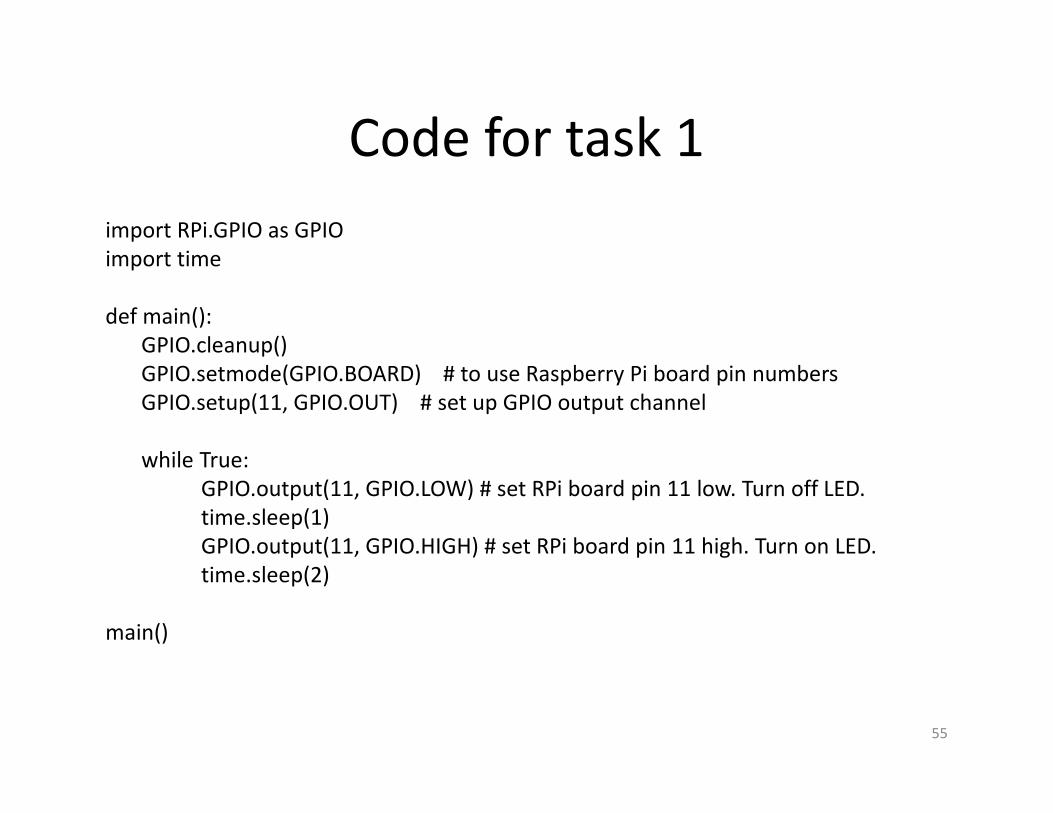
import RPi.GPIO as GPIO
import time
def main():
GPIO.cleanup()
GPIO.setmode(GPIO.BOARD) # to use Raspberry Pi board pin numbers
GPIO.setup(11, GPIO.OUT) # set up GPIO output channel
while True:
GPIO.output(11, GPIO.LOW) # set RPi board pin 11 low. Turn off LED.
time.sleep(1)
GPIO.output(11, GPIO.HIGH) # set RPi board pin 11 high. Turn on LED.
time.sleep(2)
main()
55
GPIO as Input
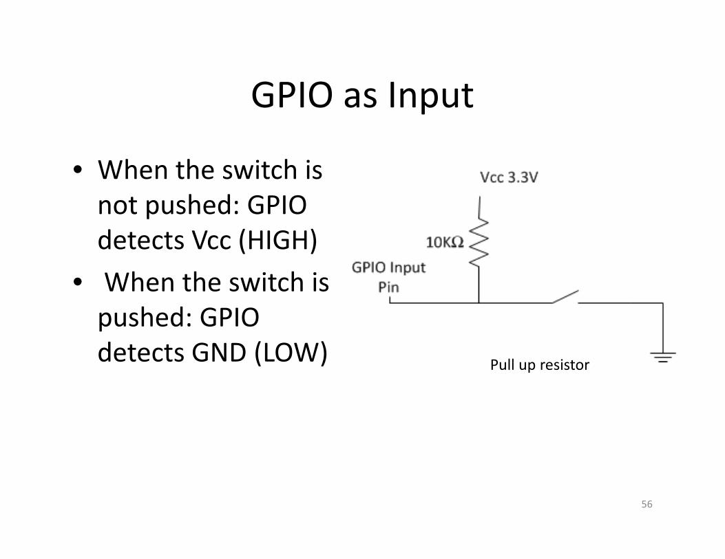
• When the switch is
not pushed: GPIO
detects Vcc (HIGH)
• When the switch is
pushed: GPIO
detects GND (LOW)
56
Pull up resistor

GPIO Input Sample Code
• import RPi.GPIO as GPIO
• # Use the pin numbers from the ribbon cable boardGPIO.setmode(GPIO.BCM)
• # Set up this pin as input.GPIO.setup(17, GPIO.IN)
• # Check the value of the input pinGPIO.input(17)
• # Hold down the button, run the command again. The output should be "true".GPIO.input(17)
57

Check input using polling
input = True
prev_input = True
while True:
input = GPIO.input(17)
if (prev_input and (not input)):
print("Button pressed")
#update previous input
prev_input = input
#slight pause to debounce
time.sleep(0.05)
58
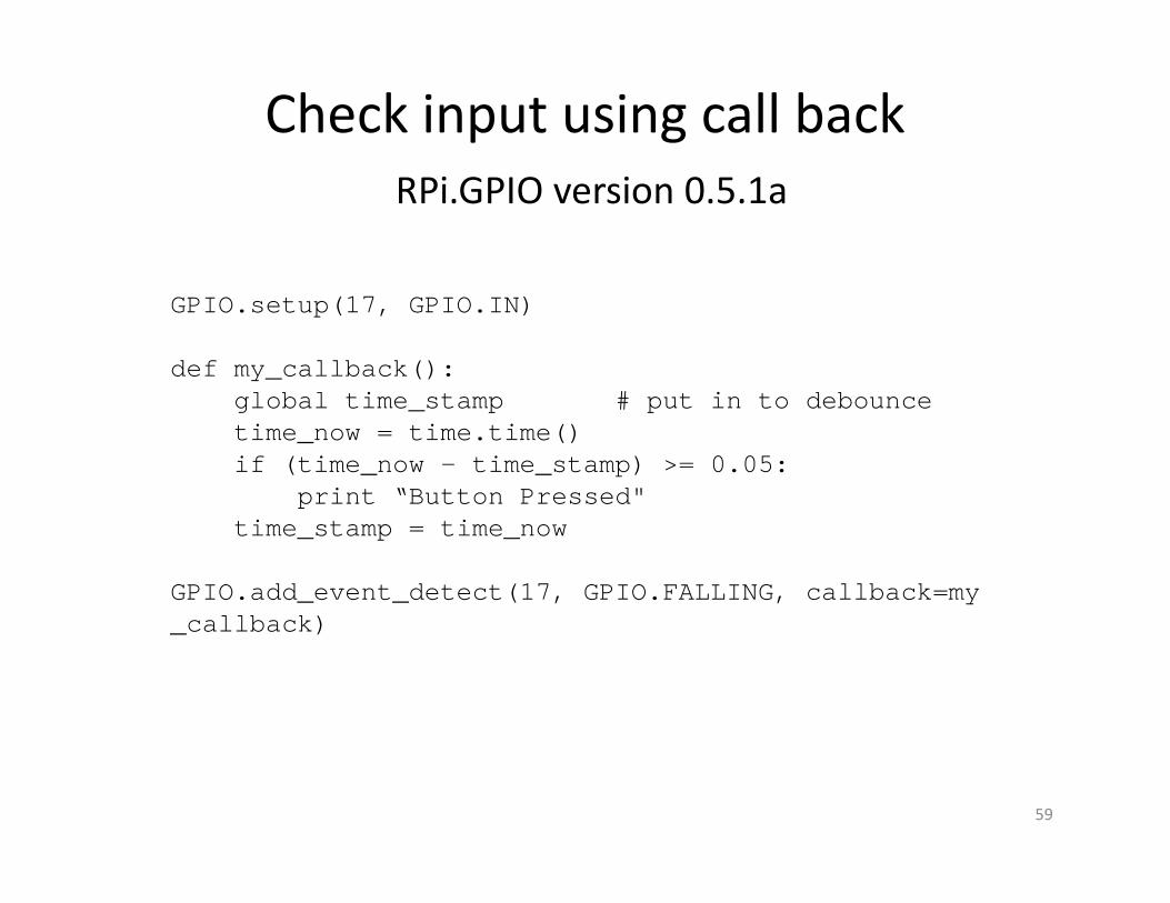
Check input using call back
RPi.GPIO version 0.5.1a
59
GPIO.setup(17, GPIO.IN)
def my_callback():global time_stamp # put in to debouncetime_now = time.time()if (time_now - time_stamp) >= 0.05:
print “Button Pressed"time_stamp = time_now
GPIO.add_event_detect(17, GPIO.FALLING, callback=my_callback)

Experiment 2: Display digit on 7-
segment LED
60

Experiment 2: Display digit on 7-
segment LED
• Most direct way to control display:
– Connect pin 3/8 of 7-seg-LED to Vcc
– Connect the other 8 pins to 8 GPIO pins
– Configure the 8 GPIO pins as output
61

Experiment 2: Display digit on 7-
segment LED
• For example: display “2”
– Turn on segments A, B, D, E G.
and turn off segments C, F, DP
– Set A,B,D,E,G to LOW
and set C, F, DP to HIGH
– Set Pin 7, 6, 2, 1, 10 LOW
Set pin 4, 9, 5 HIGH
62

• The most direct way uses 8 GPIO pins.
• If we only display 0-9 digits, this is inefficient.– Use BCD to 7-segment decoder to display digit
• How to display multiple digits?
63

Using I2C:
Control 4 digit 7-segment display
• How to do multiple 7-
segment display?
– Multiplexing
• The driver chip behind
it will do this for us
• We can control it
through I2C
64

Configure I2C
• Add modules– Add two modules to the end of file /etc/modules :
i2c-bcm2708
i2c-dev
• Install I2C tools utilitysudo apt-get install python-smbus
sudo apt-get install i2c-tools
– If we have file: /etc/modprobe.d/raspi-blacklist.conf, comment the following two lines:
blacklist spi-bcm2708
blacklist i2c-bcm2708
• To see all the connected devices:– sudo i2cdetect -y 1
65

Control 4-digit 7-Segment Display
• Connect the 4 digit 7-segment display:
– Four pins
– Vcc, GND, SDA (Serial Data Line), SCL (Serial Clock)
• Use Adafruit’s library to control the display:http://learn.adafruit.com/matrix-7-segment-led-backpack-with-the-raspberry-
pi/using-the-adafruit-library
• All the low level I/O: Adafruit_LEDBackpack.py
• 7-Segment Library: Adafruit_7Segment.py
– writeDigit(charNumber, value, dot=False)
– setColon(state)
66

Experiment 3: Temperature Sensor
• Maxim: DS18B20+
• Operating temperature: -55 °C to +125 °C
• Accuracy: 0.5 °C (-10 °C to +80 °C)
• Datasheet:
http://datasheets.maximintegrated.com/en/d
s/DS18B20.pdf
• Request free sample at:
http://www.maximintegrated.com/
67

68

DS18B20+ Features
• Unique 1-Wire® Interface Requires Only One Port Pin for Communication
• Each Device has a Unique 64-Bit Serial Code Stored on an On-Board ROM
• Requires No External Components
• Thermometer Resolution is User Selectable from 9 to 12 Bits
• Convert temperature to 12-Bit Digital Word in 750ms (max)
69
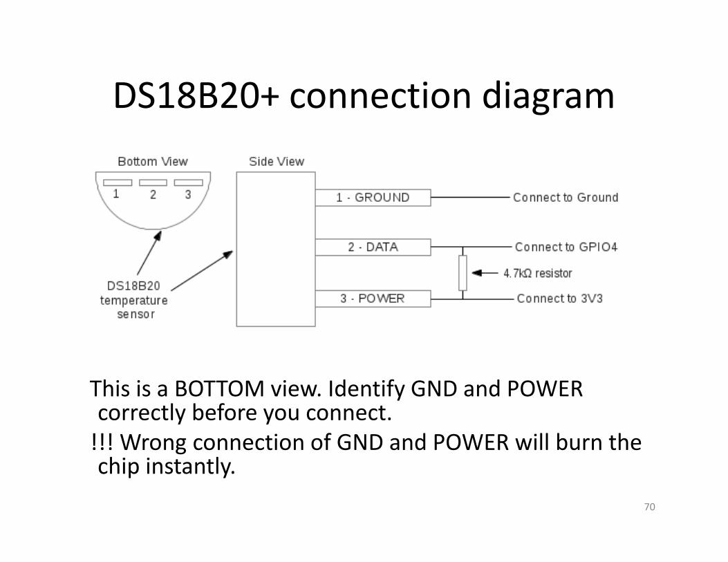
DS18B20+ connection diagram
This is a BOTTOM view. Identify GND and POWER correctly before you connect.
!!! Wrong connection of GND and POWER will burn the chip instantly.
70

How to read data from DS18B20+?
• Look at DS18B20+. Follow the 1-wire protocol.
– 1-Wire is a device communications bus system designed by Dallas Semiconductor Corp. that provides low-speed data, signaling, and power over a single signal.
– Multiple 1-wire sensors can share the same pin
– See http://en.wikipedia.org/wiki/1-Wire for details
– http://datasheets.maximintegrated.com/en/ds/DS18B20.pdf
71

Read temperature
• We do not need to implement the 1-wire protocol ourselves.
• We can read temperature from a file
– sudo modprobe w1-gpio
– sudo modprobe w1-therm
– cd /sys/bus/w1/devices
– ls
– cd 28-xxxx (may need change to match serial no.)
– cat w1_slave
72
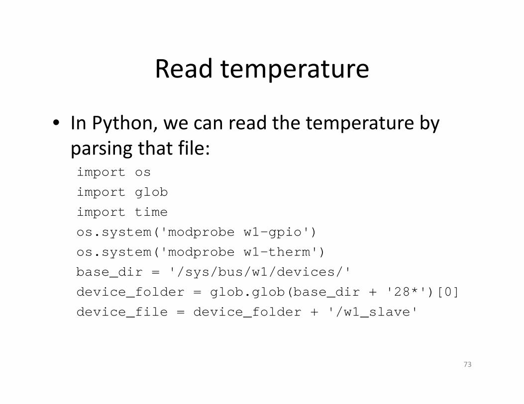
Read temperature
• In Python, we can read the temperature by
parsing that file:import os
import glob
import time
os.system('modprobe w1-gpio')
os.system('modprobe w1-therm')
base_dir = '/sys/bus/w1/devices/'
device_folder = glob.glob(base_dir + '28*')[0]
device_file = device_folder + '/w1_slave'
73

Python Socket Programming
• Two types of sockets:
– Stream & datagram
– streamSock = socket.socket( socket.AF_INET,
socket.SOCK_STREAM )
– dgramSock = socket.socket( socket.AF_INET,
socket.SOCK_DGRAM )
74

Sample Code: Stream Client
75
import socket
clientSocket = socket.socket(socket.AF_INET, socket.SOCK_STREAM)clientSocket.connect((‘192.168.2.10',23000))clientSocket.send("Hello World\n")
# data receive from server and printprint clientSocket.recv(100)
clientSocket.close()

Sample Code: Stream Server
76
import socket
serverSocket = socket.socket(socket.AF_INET, socket.SOCK_STREAM)serverSocket.bind(('',23000))serverSocket.listen( 5 )
while 1:# wait for client’s connectionclientSocket, (remoteHost, remotePort) =
serverSocket.accept()# receive data from clients = clientSocket.recv(100)# send data back to serverclientSocket.send(s)clientSocket.close()

Experiment:
LED controlled by remote sensor
• 1st Raspberry Pi board houses temperature sensor
• 2nd Raspberry Pi board houses an LED.
• The sensor reports the temperature to the 2nd
Raspberry Pi board. LED will be turned on when the temperature is higher than a threshold.
77

IP Camera Setup
• Turn a USB-based camera to an IP camera
• Install “motion” package
– sudo apt-get install motion
• Start “motion” service
– sudo services motion start
• Configure “motion” in /etc/motion/motion.conf
Daemon = OFF to ONwebcam_localhost = ON to OFFwebcam_port = desired port number or 8088control_port = desired port number or 8089
78

IP Camera Setup
• Let the motion service start automatically:
sudo vi /etc/default/motion:“start_motion_daemon=no” to “yes”
• sudo service motion restart
• View video from webcam
– http://192.168.0.85:8088
• Remotely control the web cam settings:
– http://192.168.0.85:8089
79
References
• http://en.wikipedia.org/wiki/Breadboard
• http://robig.net/blog/
• http://www.societyofrobots.com/electronics_led_tutorial.shtml
• http://macao.communications.museum/eng/exhibition/secondfloor/moreinfo/Displays.html
• See http://en.wikipedia.org/wiki/1-Wire for details
• http://datasheets.maximintegrated.com/en/ds/DS18B20.pdf
• http://learn.adafruit.com/category/raspberry-pi
80