(facsimile copy) ohio hl~mrical --. scx:iety oi ... · oi-iiohistoric inv'entory . ... corn...
TRANSCRIPT

e OHIO(facsimile copy) Ohio Historic Preservation Office c::7'-. Hl~mRICAL --. SCX:IETY
1985 Velma Avenue Columbus, Ohio 43211 S1l'CE I88SOI-IIOHISTORIC INV'ENTORY 614/297·2470
5. Historic or Other Name(s) Building 64, 65, 66. 67,68, 69, 70,73,74. 75,76.95,96,97, 123, 124, 125, 126, 144
1. No. /2. County
CUY-4608-15 .~_.~ah~:a 3. Location of Negatives Gray & Pape, Inc.
Roll No. Frame 15,17,18 (C.OI"\1'<:\
4. Present Name(s)
NASA Lewis Research Center Propulsion Systems Laboratory D Coded
...-::>
~ z, 0
"""E;O cp en
.._.... ...._._-_...~---------- ....._.....-.._---_._---_.
28. No. of Stories _._-------------.----
29. Basement? Yes (XJ
...__ND..~..g....~...._.._. 30. Foundation Material
concrete
41. Distance from and Frontage on Road
varies from 150' to -30'
40. Chimney Placement
Side
27. Other Surveys in Which Included
22. Original Use, if apparent technical facility-""_....."'---------------------------_._---------------------_._-------3. Present Use technical facility
24. OwnershipLakewood
j N
9. U.T.M. Reference Quadrangle Name
17 Zone
30~~ ~O-
46. Prepared by d (' Debm.A. M£.~C:!:,la"!.n~e ........ ti.. ~ 47. Organization .!' ~
~~~~&~te~P~;~~;r~d"i-;;"Fi;id'~""-"'- ~ ~~
42. Further Description of Important and Exterior Features (Continue on reverse if
Building 66, the PSL Access Building, is a two-story, T·shaped plan building with a concrete foundation and flat roof. The building is clad with horizontal profiled metal siding. The main entrance to this building is centrally located on the west facade, which faces onto Walcott Road. This entry consists of a set of metal doors with glass insets with a boxed metal canopy above, A concrete stoop is located in front of the entry. Two spans of windows flank this entry. These windows are multi-paned factory-type windows, some of which are glazed with clear glass while others are filled with frosted or opaque glass. The (cont'd)
43. History and Significance (Continue on reverse if necessary)
The Lewis Research Center was establ ished in 1941 as the Aircraft Engine Research Laboratory of the National Advisory Committee on Aeronautics. The AERL served as the propulsion research center of NACA until 1958 when the lab became part of the newly-formed National Aeronautics and Space Administration. As a part of this organization, the LeRC has continued its aeronautic research, (cont'd)
44. Description of Environment and Outbuildings (see #52)
The PSL Complex occupies an entire block within the Central Area. Parking is permitted on the ~orth and south sides of the complex at designated sites. Areas of lawn are located on the Walcott and Durand Road sides. The cooling towers are located across Walcott Road in a remote area near Abram Creek Valley,
-4-5-.-So-u-r-c-es-of-I-n-f-o-rm-a-ti-o-n----------------------------J1;........;Aay'"-',_1_9_9~6_~ ..~.__ ,c -~ - ..~-_I ~ ,..
49 yPlans of Buildings and Structures, NASA LeRC Overall Cultural Resource Reconnaissance Survey t-__._R_e_v_is..e_d_b_ ..•5..0a._.Da..t.e _ 1~ Real Property Records, NASA LeRC, Real of NASA Lewis Research Center, Cleveland, Ohio,
1
SOb. Reviewed byProperty Division Gray & Pape. 1996 (Cont'd)

51. Condition of Property 54. Farmstead Plan
o Excellent o Ruin N00 GoodlFair o Destroyed/Burned o Deteriorated
Date
52. Historic Outbuildings and Dependencies Barn Type(s)
Corn Crib or Shed 0 Smoke House 0 Privy 0 Summer Kitchen 0 Spring House 0 Garage 0
Silo 0 Ice House 0 Designed landscape 0
53. Affiliated OAI Site and multiple
Archaeological Features: Observed Expected on Basis of Archival Research
Well -----l Privy _ ...--J Cistern _._._.._-.1 Foundation -----l Structural Rubble .__ .J Formal Trash Dump ~
Other ~
42. (Cont'd)
symmetrically arranged facade has a long expanse of windows on the second story. The north facade of this building is clad on the first story with metal panels and on the second story with profiled metal siding. A large span of multi-pane, factory-type windows is located on the second floor. A second floor entrance islocated on this facade and is accessed by an exterior metal staircase. The south facade of this building has a cargo door flanked by an entry door and short span of multi-pane windows. The second floor contains a large span of these windows. This building was constructed in 1951 by the Sam W. Emerson Co. ofCleveland, Ohio. (Cont'd)
43. (Cont'd)
while also advancing technologies in aerospace propulsion, and space flight systems.
The Propulsion Systems Laboratory is an altitude simulation facility capable of testing full-scale gas turbine engines operating continuously at simulated altitudes up to 70,000 feet and simulated velocities up to Mach 3.0. After components are tested at other facilities at the center, complete engines are tested at the PSL. The facility consists of two engine test cells, which measure 24' in diameter and 38' in length. Flight simulation is achieved by closely controlling test chamber altitude as well as the inlet-air pressure and temperature, so as to match flight conditions. These test chambers are capable of testing large-scale airbreathing engine systems under controlled simulated altitude, temperature, and pressure conditions. Modifications to the test chambers, supplying inlet air in limited quantities at temperatures up to 3000 F, allows testing in the hypersonic regime (up to Mach 6.0). The PSL support complex includes central air system equipment, an exhaust-gas cooler, a closed-coupled air temperature conditioning plant, and a cooling tower water system. System studies in the PSL evaluate engine thrust, fuel consumption, airflow, stall limits, blowout limits, temperature, pressure, fuel distortion and starting characteristics. (cont'd)
44. (Cont'd)

--3. Roll 3 Frames 7, 8, 10, II, 14 Roll 6 Frames 2, 3, 4
Photographs provided by NASA: C-90-093 I I , C-90-09295, C-90-09352, cutaway schematic, C-79-4008, C-68791
5. Central Air Building; PSL Altitude Chambers (2); PSL Access Building; PSL Primary Coolers (2); PSL Secondary Cooler; PSL Tie Lines: PSL Cooling Tower No.3; Service Support Building (Control Components Laboratory): PSL Cooling Tower Water Pump Building; Substation "J"; PSL Combustion Air Heaters (3); PSL Dessicant Air Dryer; PSL Fuel Storage Building; PSL Oxidant Storage Building; PSL Primary and Secondary Cooler; PSL Heater Building; PSL Engine Test Building; PSL Cooling Tower No.6; PSL Turbo-Expander No.2.
20. Treadwell Construction (65); Sam W. Emerson Co., Cleveland, Ohio (66); R. Hansen Co., Cleveland, Ohio (Foundation at 70; 74); Foster Wheeler (Cooling Tower at 70); John G. Taubman (73); Pittsburgh-Des Moines Steel Company (123); Neville Island, Pittsburgh, PA (123); Gillmore-Olsen, Cleveland, OH (124; 125); Fluor Corporation, Santa Rosa, CA (126); Feldman Mechanical. Cleveland, OH (144). Contrators working on Substation "J," Building 75 included: Westinghouse Corp .. Collier Construction Co., General Electric Co.. Phillips Electric Co., and Hansen Co.
42. Building 65, the PSL Altitude Chambers (2), connects to the eastern end of Building 66. This building is a two-story, concrete structure that is rectangular in plan. Spans of multi-pane, factory-type windows are located on the north and south facades on the second ±loor level. Some windows are also located on the first ±loor, but these are obscured by a series of large steel pipes. This building was constructed between 1949 and 1952 by Treadwell Construction Co. and consisted of two steel tanks supported on concrete foundations.
Building 97, the PSL Oxidant Storage Building, is a detached shed like structure. It has a concrete foundation and a gable roof covered with interlocking metal. It is clad with vertical metal siding. Windows are located on the north and south facades and are eight-pane. The west facade consists of a large cargo door, while metal entry doors are located on the south and north facades. These doors are covered by thin metal shed roofs. This building was erected in 1964 and measures 50' by 16'.
Building 95, the Desiccant Air Dryer, is a one-story, concrete structure that is square in plan. It appears to be clad with transite panels and has a flat, built-up roof. Strips of factory type windows are located on the west and east sides. A metal entry door is located on the east. Two large dryer tanks are located to the north and south of this building. This building was constructed in 1955.
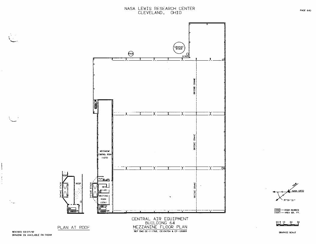
Building 76, the PSL Combustion Air Heaters, consists of three large steel tanks set on concrete foundations. Two of these heaters were installed in 1952. Building 64, the PSL Central Air Equipment Building, is a large square building that consists of a brick base approximately 6' in height, a concrete sill, and horizontal profiled metal siding above. The building is a one-story structure with a mezzanine and basement level. It was constructed in 1952 by the Hunkin-Conkey Construction Co. of Cleveland. The west facade, which faces onto Westover Road. consists of a long expanse of multi-pane, factory type windows that is centered on the top level and a cargo bay on the western end that is accessed by a concrete ramp from Westover Road. A pedestrian access door is centrally located on this facade and consists ofa set of concrete steps and a set of double glass doors with an upwardly curving canopy. Two projecting brick vent stacks are located on the eastern end of this facade ±lank another overhead cargo door that is also covered with an upwardly curving metal canopy.
Building 123, PSL Primary and Secondary Cooler, is a large pill-shaped steel structure that is connected to Building 125 by way of additional steel pipes. This building includes an exhaust plenum, dry cooler, de-mister and water cooled shell. It was constructed in 1972 by Pittsburgh-Des Moines Steel Company of Pittsburgh.
Building 125, PSL Engine Test Building, consists of two units. The front part of the building is two-stories and rectangular in plan with one half clad in brick and one half clad with profiled metal siding. The wall of the brick portion of this building is articulated by brick pilasters. The main entrance to Building 125 is located in this part of the building and consists of a set of double glass doors, glass sidelights and glass transom. The entry is covered by a curved metal canopy. The profiled metal portion of the building has a long strip of multi-paned, horizontally divided windows on the first ±loor.
The rear unit of the building is completely clad with profiled metal siding with a one-story brick addition on the south side. Two overhead cargo doors are located on the north facade of this building. This part of the building houses two large test chambers.
Building 70, PSL Cooling Tower No.3, is rectangular in plan and three-stories in height. The frame, 10 cell cooling tower rests on a tall concrete foundation with walls of corrugated plastic. The lower portions of these walls are louvered, supported by wooden joists, and covered with screen. Access into the cooling tower is located on the southeast side. Building 70 is joined to Building 126 on the southeast side by a system of catwalks. Building 126, PSL Cooling Tower No.6, is similar in construction and materials to Building 70. Located on the southeast facade of this building there is a one-story concrete structure that is rectangular in plan. This building appears to function as a pump house. Access into the building is by a single metal door located on the north facade.
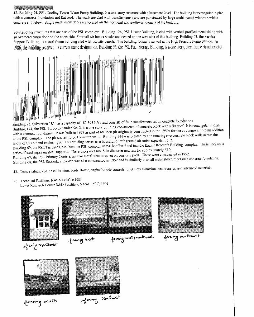
.iII&~ 42. Building 74, PSL Cooling Tower Water Pump Building, is a one-story structure with a basement level The b 'Id" I . with a concrete foundation and flat roof. The walls are clad with transite panels and are punctuated by I~ge m IUt·l mgdls r~cdtangu ~ Ihn plan concrete sl'll b I S' I tid u I-pane wm ows Wit a e ow. mg e me a entry oors are located on the northeast and northwest comers of the building.
Several other structures that are part of the PSL complex: Building 124, PSL Heater Building, is clad with vertical profiled metal siding with an overhead cargo door on the north Side. Four tall air intake stacks are located on the west side of this building B 'Id' 73 th S .S rt B 'ld" If b" . Ul mg , e ervlce
uppo UI. I~g, IS a ~tee .rame Ulldmg clad :vith ~ransite. p~els. The building formerly served as the High Pressure Pump Station. In
19861
the building received Its current name deSignation, Bulldmg 96, the PSI, fuel Storage Building, is aone-story, steel frame structure clad
I I
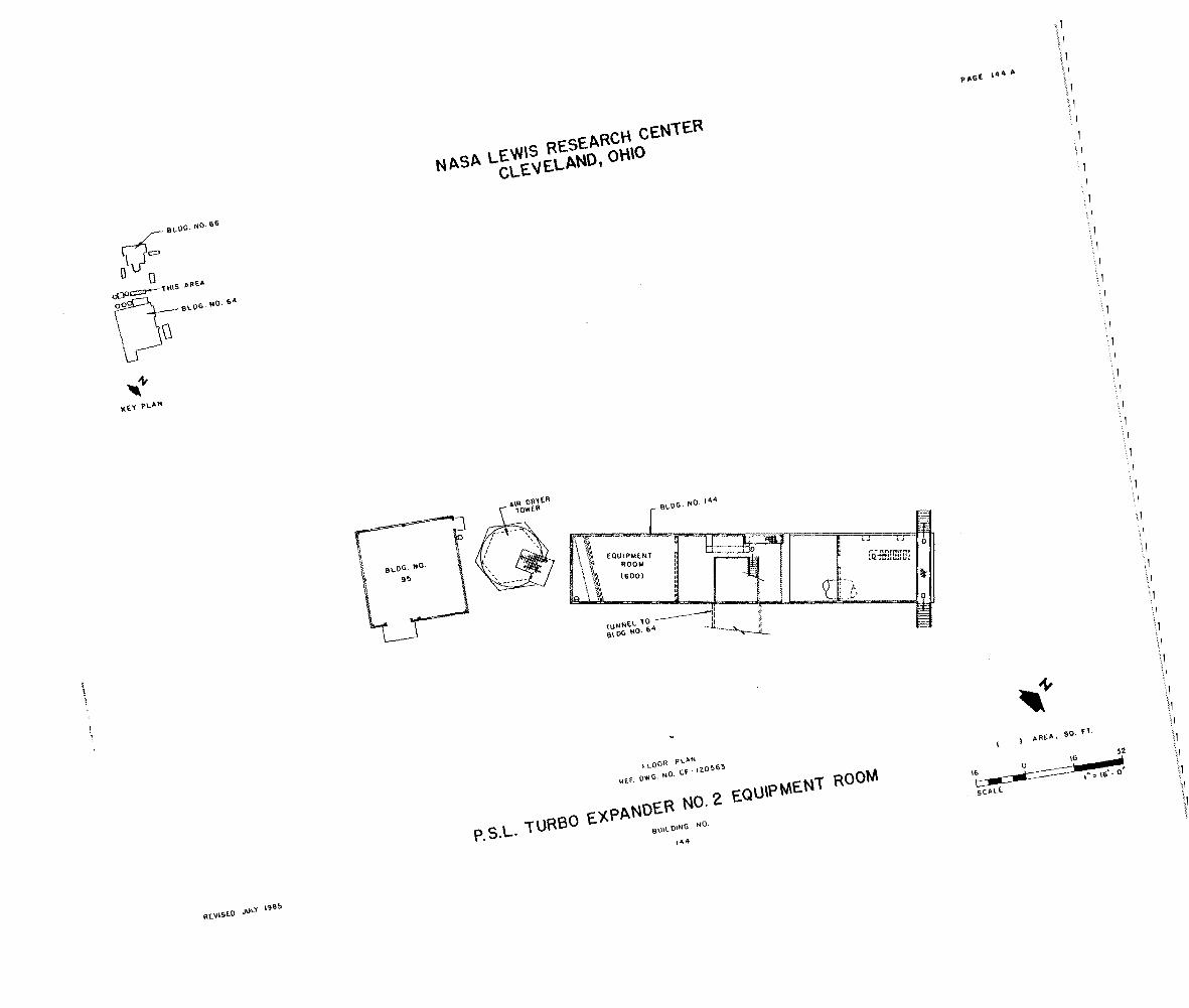
! "~IJW Building 75, Substation "J," has a capacity of 182J95 KYa and consists offour transformers set on concrete foundations. Building 144, the PSL Turbo-Expander No.2, is a one story building constructed of concrete block with a flat roof. It is rectangular in plan with a concrete foundation. It was built in 1978 as part of an open pit originally constructed in the 1950s for the col/warm air piping addition to the PSL complex. The pit has reinforced concrete walls. Building 144 was created by constructing two concrete block walls across the
width of this pit and enclosing it. This building serves as a housing for refrigerated air turbo expander no. 2. Building 69, the PSL Tie Lines, run from the PSL complex across Moffett Road into the Engine Research Building complex. These lines are a
series of steel pipes on steel supports. These pipes measure 6' in diameter and run for approximately 510'. Building 67, the PSL Primary Coolers, are two metal structures set on concrete pads. These were constructed in 1952. Building 68, the PSL Secondary Cooler, was also constructed in 1952 and is similarly is an all metal structure set on a concrete foundation.
43. Tests evaluate engine calibration. blade flutter, engine/nozzle controls. inlet flow distortion. heat transfer. and advanced materials.
45. Technical Facilities. NASA LeRC, c.1983 Lewis Research Center R&D Facilities. NASA LeRC, 1991.

Q
">0"'1""""''';' • , ..:''' •• ~l (~ "Ie "
II I·. I_:',.(,ax 01_'''''111'''.1 ..(1''' .........
I'" ",-,,,,,, ~'\ "a.~,. '" ,11 >0(111,.. ~'I 0(1 D"'O I
111":1""""1"'.''''0'1 11""..... 1' '· ... ' " ......'ICvI .... lV"D" In .~" .. ,..... , .~~ IL....ou' tn"
·\..,1""""·(_....1" I "1""" ",,"""\000 ,.. ~.
,\ ''''''"~O'[_'('I I'
01 ..., ....... (00).,.,./, III '1'f."'.... "II I, .." I"" 'I, ,0.1'" I...... ~.., ,
'"''''''00'00'''.( III (""'."(""1'''''U "~If\'''(~',_,
.. ·\<\l,,",oU,(<;>;l"'I·
.. ...,1(,.11
10 .""'.1""(11'0,."" I
In D1'''''''')O<lll'I'('''' l.ll ""~l>IIPF~~""'II""""',D'•
"I 1L'(;~'''II''(~ ,"'~f""""''' ,,", (ISutSl'l(JOo·1
.. 'f(_ .. I' • ....:;II .. ~ ..
'I (c.. ,t",(Jo"U«loll",(jII"O'"
" ..., (00 ,." '1)00(' ,tOUO ..... "'~{
" "'i,I"U"'''''
"""·(,II;·"I·"'IJII",.I'·'"'' 1'/ ·""\j'!O,P(I,()'<'III,.c.,r;
11l1"'("""ll\l""·C,II.
l\ ""~.I"'''' • "'"cro'"I''(Jo·''-oIarlO''' • "HUT( .. O"Ul ..... Ol'I .. , ... ot 'Ih\'O"",,_'l(lf'o("'·'OI'''''"' I" ~""('1 UI"'~"(II)1~
II ....OUC'O(UollI..(\ " ..... r~ .. " I.... """".".OOO1C...._.
II lOll".",").('IoOG
III (('N',-"'~I\ CL' ..... '· "",,1' .~~"
111"""""\,,,,,/
"'''''1-0.11,1')''', "(00.""('101I0..01 till I•• ,,,, ~,(lI.LI"1 ,,, .... ",,'I(
"I"oo:"'(I"'III"fl";'; I' ("OCl~O( 1"""11',0' I" (0_"'("1(1,.., ... ""'11>"'"''
",1·\( ...... 0 .."1"10..'('10· • \("It,,,, ...,."""'I'.'uo..., lI·'O I ... ·"""' .. ..: l'O ,)<1""" ... ' II _.<A'o( .... 'U.Ull....,..
II \"110'00·(
nhu.. "",( ...""ILOIOI"""·
10 IW'_"''''.,Io'IOOo',D(;" ·o<·n,·.,"·'''''·''"'';· II lit _'_1''''( _lit 1""'_1'.""1"10""" .. r •• l~"I.'H""_'f\_Il'.lO' ,.,
.11 \ ..'0.' ~ 1 \"'00·1 II 1 110100' .. e.t1-.l'lloo..'>l 0'
1\ ~.l.." ~I
• r.1 ,''' t::.o.., '()Oll '0(; 1
• .c(\ S'~'''''''''I''' • ·"II".I.,'Olllfl,·I""·',·'
'11".'1('10:-\<-'
'1 -"'''''''''-.('''''0''''(10' \,\ ,,' I"'.'·"III.,"'('O\IU
... r ,I· I'"" 'nf"{~' [,",,"'" ..."
.. ".I",_,I ...I··..":-.IG " 1'"""'"......-O;:I,·I:lI·' .... '>l , ,. I"". ~I"I' a:: 'II 1.'1\\'1'000" oC , ...... IH"-':III.~(
... ·ot-o.'StOlCI
" '1I'.lf\" .. """..: ....D'c....."'w·· • If. Ill' 1.' (I' 'II ~ "-"",,," """ P If .10;'" \lUt,:>", [3""'Hn' "0"11,'"
.. 'W, \~ I.' 1,.'I'OIl(>O, •
oc 10, It I'" ~.'" (W"''Ie-. ""'.1 .. 00 '1 ,~, I~ I,"""", ..,II".' '"n ...,.. 1"'.00.
'1 F~, II I"" ......... '11 .... ' 'un ..... "DC
f1 •• ,III' I'" '00l ..' I"",. '00 \
0\ ... , ~'I\O( '"1 .,. PO-" .. "'1'~1' II ...... 1.0"
" '1l O"~"" SIJ"'" 110.
• 1~,;,""{[)OoO"""'''1 .,11.0<'''''"''''''00' ..... ' "'.':(»o'I"I'Oo'.-oI"!'
,01: '(1('(100'1'''''''11,0. ,:r I~C' ... ,(»O,_"',.'Sl o, ..... ,,'...
Ie ,....,~~'"'''' "'I' '"(""I ,.\..\ " 1(11 ~ ... Ct
I~ W'II"o.\ ";;<fll".",()lI"OOIIJ. UI( ~·'!""II"O"'()lI'
Ill' c.·,...." ... IOL .... (~' I ,,"'co, '(""" C'
III' ."1 ....... \1 "."""~ ;.,·'Il 1'''1(0,
IJI '''''''O'o{~'; tl, ......, "{l Ll_
,l; ... 1(.,"\I\lt'HII .... "".-,~,,"
OCl<l'Y.IO· ...·
/III '''"''''0.,lIJ."'-'!'fNC.,,.,,,I",I;I" ,IJ) ' ••"~If ...(~h·(1 ",,,,,,,,,
iD' ~".... 0'0 f1~I'.1 1(1""'·,"" ,d" ~ I
1)\ \r"," ..o "(>,,,, "'~\lU' I'" •• :., "I' o' 110 ,.,,)~,~,{ ..>'{.t'l,. """". (, ,
II' lu' \(. "0•• I '0"'<:' I,~'
D '..:)'1 e:.-O<,~DI ... ,«f''''~''''P. '!!~~'!!
III ....""CtOC~l W041"~(! "~'
m, l,,~l1 ,[ '.U.u, \...,,, ._1""",,' 101 1..... , ("""ll'I'(;~I"O"'(~'
Il)O IIO'''Ct I"~
1CllI'(·..<;"·\I .... '
o 0'000<'.'" \lQ..""'_
»f ~i'-U" \\011:'';( ......
.. ">,,[( I~'Q 'OIl: "I .,~ r,,' ..!-:. Ill' 1'.(' 1. 'I\l~'(" ..• ~,' •• ""
'Ili "'H, ,'C_~"""(.
II' .~~';;'~:'.'";~\"..\.!\
u. (Co .. !'", I""~'
II' ""'1.,,0' \~1l'(I
l~ .(("".o~ "",''\ I,~'.
'" ,u'",,"'llJ1~IC'II(rx.
"'''''1'''''\''''1\''
..".,~ "I}
llJj :,_",,,· .. "I,,,,·,."",(,I,"
'<)1 OI'f,D""'"' '~","'I''''( ',0' W ',"1-0"'1,,,)1'"
tOO 0 /fJ' ~~l MIl .~.~.~.~.;"!_ .....!=-~~
"r>11
o
./
CD 1l1"lO-J) A
klVISEO AlJGUSlI). 1911
(
/'
OJ I","~ "'W' '"' "" ,,," .., '" .... fLIP\'"Jl!.\·,,...-•• ,
Q

I
I
I NASA LEWIS RESEARCH CENTER I
CLEVELAND, OHIO I
I
I
I
I
I
I
I
I
I
I
I
I
I
I
I
I
I
I
I SEE INDEX fOR BUI~DING pLANS
I
50 0 50 \00 150 200
p~AN
-=-=-=====_1__t:1==:=:J1__dlli I SCALE ,",50'·0"PROPULSION SyS1EMS LA60RA10RY GROUP I
I

• • •
II_
NASA LEWIS RESEAkLH LENlck CLEVELAND. OHIO
AREAWAY
I o
RETAINING WALL :COIf'RE!~ETAINING WALL
'•• ,.(:1 Ii ~ tCOMPR~OR __•
8 o.. .' i ,.ST ACK tEXHAUSTER ~ : Jltj;====.... • • .. .. 0 .
:COMPR~iiR"'" '.~1 0 D~ ::~ • i.....-•.;.-'-.--. , a ----- '. CI • C • • .. o. . I I .' ~ tEXHAUSTER 0 _0__ o
c c • • 0 • OJ 0
-Il-Jl--Jl--- --Jl---- __---I- --IL--, r-·" .. ···_-····" ......MEZZANINE ABOVE ---lnl
GENERATOR PADS ,. ELECTRICAL 13431DOD l~foERAT(jl PAC4 Itk if
i.'-"':_~.. • • "'~--II'" INTAKE SYS.
TACI<SINLET PLENUM
HATCH ~'~;i ABOVE ~~~
TACK iSINLET I PLENl.!M
INTAKE SYS.
,I .. TUfj.. '. j '•• '..'
STEAM : ~1i.A~US;,,;T~ER~---- _C _ C C
TRENCH'....., pn
ENrfARt;OOi 0 0 :::::~!JO ~~ ,0,[[[] ~ • ... "IC·I : ~H.!'",US"lT~ER~ _
~ • ,... ,.C. ,opn, ~ , I -dIIlII&upl I I I I I
PIPE~ZZANINE ABOVE
1 CHAMBER.. '
(:I
AIR
AIR
.,(:1 !cO:LSQRi' ~._.... .. . . .... •• ": -D:~~S;IELEC .: ~1143)" • ;1 i •
,
C· . .i····· • , 'CdSSCll~_.' ••
, .up~It ., • .,- • (j /'\-RAILING
CENTRAL AIR EOUIPMENT BUILDING 64
BASEMENT FLOOR PLAN
_ .. LGRIO ~ o
EXHAUST DUCT
~ - ROOM NUMBER (XXX) - AREA sa. FT.
REVISED 03/25/92 REF DWG CE-I 11761. CD-II6064, CD·II2'52. GRAPHIC SCALECE-'04748. " CEIOHOI. CF-'20886DRAWING IS AVAILABLE ON CADAM

• • • •
• • •• •
•
PAGE 64BNASA ~E~0~LARNEDSEARCH CENTER . OHIO
AREAWAY
UP
, ~.
t EXHAUSTER ~
'.. '.."
AREAWAYQ,. • .~ .. 'I ..
S~STEM - -
SYSTEM --
8 INLETPLENUM
i~~lf~'<J
8 INLET PLEMJM
SYSTEM _.
. .Q., • '. i • •tCOMPR.<SSOR
· .: (j
.,~ .,., CENTRAL AIR EQUIPMENT
'n•
'j
8 .. C., •e, e .. ., • I·---- .. • • .. ~
e
e
e
I, ~ .. >-<0 0 -<0 0 , c 0 • • .' • ". '"t COMPRESSOR we a: -<
8 • ,.8- .c.c. .. ... • ...' a·' • •
e et EXHAUSTER e n
AIR INTAKE P
'. 0 j o 0' 0..10 . ..'
Q ,• • . •• o
• 0
• '.0
0
10· • • c. c.· 0 0., ,.0. ,. • ,. .1 ~I
In
SWITCHGEAR AREA.
MEZZANINE ABOVE
AIR INTAKE BASEMENT I (2862)
.,Q .' Q ,g __--"t>-IC,J,REss<l ' · • .'•
Q · • ".• •
, ,
•AIR INTAKE
• · .' o EXHAUST
DUCT
~ - ROOM NUMBER lXXXI-AREA sa. FT.
BUILDING 64 BASEMENT MEZZANINE FLOOR
REVISED 03/25/92 REF DWG CE 111761. CEI04704 ~ CF -120B87 PLAN GRAPHIC SCALE
DRAWING IS AVAILABLE ON CADAM

NASA LEWIS RESEARCH CENTER PAGE 64C
CLEVELAND, OHIO AREAWAY7\.
.-Ih t
...........
.~-
.~ ~
X37"51'21.
~ - ROOM NUMBER (XXX) - AREA SO. FT.
! ..lP-CENTRAL AIR EOUIPMENT
BUILDING 64 FIRST FLOOR PLAN
VENTILATION I~TAKE ./"SYSTEM ·C·~
= JAN 40
.. MENtv! (214)
ON jlIIIIIl.
~J 51 .r_----wl r/r---...J.J'"! ~: r I
D EXHAUST
DUCT
~ ;~DN=..:!__l...l !! TBUENrJi !! I ..
REF OWG CE-111762, CE-104702. CO-112177 ~ CF-120888
DRAWING IS AVAILABLE ON CAOAM
REVISED 03126/92 GRAPHIC SCALE
NASA LEWIS RESEARCH CENTER CLEVELAND, OHIO
~
~ , .. 1.. ' ..........
EXHAUST STACK
e STA~ II
~
~
i .....
I /
/-i\1 ill ...,,
\
I____oL
I
MEZZANII£ CONTRQ ROOM
(12731
-I -
I- MEN III n!'TI
MEN
Ml'451 I I !
MEETING I IROOM
12361
CoN ·To
I I_ n10 J_ i
I I I I
!l!1<,151
~I 0:1ceq
! I, i I - I
I I_ I I_ I I_ I
i I I,, I I
~!51wi81 llil,,,
i
I I 1 I I I I Cb'
-
yO-. -i
CENTRAL AIR EQUIPMENTBUILDING 64
PLAN AT ROOF MEZZANINE FLOOR PLAN REVISED 03/27/92 REF DWG CE-111762. CEI04704 ~ CF-120889
DRAWING IS AVAILABLE ON CADAM
PAGE 640
:r!X37'5"2J.
§8J - ROOM NUMBER lXXX) - AREA sa. FT.
GRAPHIC SCALE

PAGE 65-66BNASA LEWIS RESEARCH CENTER CLEVELAND, OHIO
METAL GRATING TO~
STRUCTURE NO, 67 PRIMARY COOLERS
I, !
~ Ii Ii. lo'-t-KEY PLAN
ROOF
(1025 )
~
'" o
~ 'Q.
BUILDING NO. 66
1320) \2881
-
----l1lo
PLATFORM
INSTRUMENTATION
(~~~~) ~ AC UNIT IIr I'7l 8'1; Q ~ I!
..... _L._J_-t ...,
THIRD FLOOR PLAN
SECOND FLOOR PLAN
-'-....-, SECOND AND THIRD FLOOR PLANS
REF. OWG. NO. CO-1I1804. CO-104139 8 CO-111828
P'S.L. ALTITUDE CHAMBE RS ~ ACCESS BU I LD ING ) AREA, SQ. FT.
REVISED WARCH '98~ BUILDING NO.
ES &EE
16 0 16 32 1::1:::JI--=:::IIMiIi=:====iI'__Ii' SCA.LE I" ; 16' - ci

PAGE 70A NASA LEWIS RESEARCH CENTER CLEVELAND, OHIO
-_-_-~- • .__.c_M
hi I
I Ii I I
ooo
:[CIU I i : IDJ
/SULFURIC ACID TANK
o
PUMP PAD
o on
i I
r STRUCTURE "0. lZ6
BAS IN PLAN REF. DWG. NO. CE-I04575
) AREA, SQ. FT.
PSL COOLING TOWER NO. 3 16 0 16 U
STRUCTURE NO. I ... ! !
REVISED JULY 1978 70 SCALE 1/32"·1'·0"

PAGE 73ANASA LEWIS RESEARCH CENTER CLEVELAND, OHIO
KEY PLAN o
(776 )
o
SECOND FLOOR PLAN
(559) J II
(299)
~--~ ~---
FIRST FLOOR PLAN
FLOOR PLANS REF. DWG. NO. CD-111767
CONTROL COMPONENTS BUILDING NO.
LABORATORY 8 I
0 .....
) AREA, SQ.
8
FT.
16 !
REVISED NAY 198~ 73 SCALE 1"=8'-0·

PAGE 740' NASA LEWIS RESEARCH CENTER CLEVELAND. OHIO
u
u
(229) J i
! ILI ~'"~~ ~
CONC. WALKCONC. PLATFORMI 0BASEMENT
I I , , , ~
OPEN BELOW AT Flo El.BA:;MENT B'ECOW
I
.... .... ELEV. 733.82',.".""' ..................
... ...
~;==-=-----------_·,;;-:.:~;.;:::,."-:uetf;;=====-======e;====it-ti=====:l=====aE=======:E====n.i:; o
Fl. El. 742.55'
I WORK
AREA GUARD RAil
Fl. El. 738.92' (1034)
,I:i Fl. El. 744.50' ~ 888
O I 1,1 ~ TANK TANK TANK
SALT STORAGE1
L~~~L_-..J~;;;;;;;;;;~~;;;;;;;;;;;;t;;;;;;;;;;;;;;;;;;;;~;;;;;;;;;;;;;;;;;;~~~:;;;;;;;;;;;;;;;;;;;;;;;;t;;;;;;;;;;;;;;;;;;;;;;~I~;;;;;;;;;;~;;:;;;;;;~il- __B_A_SI_N__--.J
o
733.82'
# REF.
FLOOR PLAN DWG. NO. CE-!04579
~
REVISED JULY 1978
P.S.L. COOLING TOWER WATER BUILDING NO.
74
PUMP BUILDING )
8 0
I -.... SCALE
AREA, SQ. FT.
8 16. !
1/16'-1'·0'

P:'GE 751.NASA LEWIS RESEARCH CENTER CLEVELAND, OHIO
THIS AesR....EAo CJ., .•.•.•.•.• U·D'"--,, t:::J fJ, >~
"d . ", KEY PLAN
00
P.S.L. EQUIPMENT BUILDING 64
REF. PLAN
DWG. NO. CF-I04401
REVISED JULY 1978
P.S.L. SUBSTATION STRUCTURE NO.
75
16 01 __
SCALE
16 32 ! •
1132"·1' -0"

PAGE 76A NASA LEWIS RESEARCH CENTER CLEVELAND, OHIO
I I
P.S.L. EQUIPMENT BLDG. NO. 64
-~IKEY PLAN
~CONCRETE BELOW
Cl.. o cr: cr: UJ > o... U)
UJ X
FOUNDATION
PLAN REF. DWG. NO. CD-I04042
) AREA, SQ. FT.
P. S. L. COMBUSTION AIR HEATERS (3) ,STRUCTURE NO. .....o B 16
REVISED JULY 197B 16 . SCALE 1/16"1'-0'

PAGI t5A NASA LEWIS RESEARCH CENTER CLEVELAND, OHIOifBLDG. NO, "
o 0 000 THIS ARIA
o-.~.~ ... GUARD RAIL=="~:"fr~' ~. '" r \
ItlY PLAN
FOUNDATION OF DRYER
u, PLATFORM
(899)
TOP VIEW AIR DRYER TOWER
REACTIVATION BUILDING
BLDG. NO, 64
TOP VIEW AIR DRYER TOWER
FLOOR PLAN REF. DWG. NO. CC-104043
REVISEO JULY 19U
P.S.L. DESSICANT AIR BUILDING NO.
95
DRYER ) AREA,
8 0 1- ... SCALE
SQ. FT,
8 16 ! !
IN. e' 0"

PAGE 96ANASA LEWIS RESEARCH CENTER CLEVELAND, OHIO
KEY PLAN
PIT
u
BLDG. NO. 66
FLOOR PLAN REF. DWG. NO. CD-112879
) AREA, SQ. FT.
P. S. L. FUEL STORAGE BUILDING ,
BUILDING NO. ....o 8
REVISED JULY 1978 96 SCALE

PAGE 97A NASA LEWIS RESEARCH CENTER CLEVELAND, OHIO
KEY PLAN
IE:::JI
! I
I P,-II__P_IT_B_EL_OW_-;i I,
e- IIIi II I i ~,
I !,II I I
: nTmTIT I : - SLOPE EYEWASH
o
FLOOR PLAN 0"". DWG. NO. CD-112879
) AREA, SQ. FT.
P. S.L. OXIDANT STORAGE BUILDING o
BUILDING NO. .REVISED JULY 1978 97 SCALE 1/8' ·1 '-0'

PAGE 124110 NASA LEWIS RECLEVELA~~AROCHH CENTER , 10
KEY PLAN
RETAINING
WALL
I I I I
I I I I
4 PLATFORM
I ABOVE
I I I I I I
AIR HANDLING RM (1332) •
o D
I
I, In: iii
l~
I '" '"";:::::'1~'t~ I I
I I I I .~
II
DO U -+,I
BLDG. NO. 125
BASEMENTREF. DWG FLOOR PLAN
• NO. CF-153061
BUILDING BUILDING NO.
P. S. L. HEATER 8
I.
)
o .... AREA,
8•
SQ.
..
FT.
: 16
REVISED A PRIL 1985 m SCALE I '8' - 0"

PAGE 1248NASA LEWIS RESCLEVELAN~~R5~oCENTER
KEY PLAN
I EXHAUST STACKS
REMOVABLE PANELS
. I
I
EJ~I III ABOVEi i IFL. EL. 757.00'i IMONORA IL--l rMONORAIL
ROOF
-"'~r"'''' I I
I
, !
iII
FIRSTREF FL OOR PLAN • DWG. NO • CF-153061
) AREA, SQ. FT.
P. S. L. HEATER BUILDING
REVISED APRIL 198~
BUILDING
124 NC.
B 0
I~~-~:::J-.It::==::i.~__~16 .SCALE ,!I" , 8' 0"

PAGE 125A NASA LEWIS RESEARCH CENTER CLEVELAND, OHIO
PLATFORM
I ABOVEO
!oo
LOUVER
LOUVER
TRANSFORMER AREA ~8 Ii j' °18' I i '"D~ n
, ~ ,w,,,,",,..,·8~ .' " ..~
AIR INTAKE li"I~rV'\~lfOlOIillJliI' I I 0 0\. LOUVER !1111~ol itd!hi I I OJ' \ 0
.. .I~L.2...- I', I! o.
I I I r
KEY PLAN
, "'-."
13521 AIR HANDLING EaUIP. ROOM
CONFERENCE ROOM (690)
3
BASEMENT FLOOR PLAN REF. DWG. NO. CF-153052
REVISED MARCH 1985
P.S.L. ENGINE TEST BUILDING NO.
125
BUILDING 16
! -SCALE
0
"'"
) AREA, SQ.
16. FT.
32 ,

PAGE 125BNASA LEWIS RESEARCH CENTER
CLEVELAND, OHIO
KEY PLAN
OVERHEAD DOOR
D nl I jl DATA PREPARATION
~ ' i ROOM
(1500) 201
I
SOFTWARE STORAGE AREA
202
-----11(r;===~ i D
I {
!
MEZZANINE FLOOR PLAN FIRST FLOOR'PLAN
STACKING
FIRST FLOOR &MEZZANINE PLANS REF. DWG. NO, CF-153051
AREA, SQ, fT.
P.S.L. ENGINE TEST BUILDING 16 0 16 J2
!BUILDING NO, I,
SCALE "6' - 0"125 -... ,.. REVISED MARCH ,985

PAGE 126A NASA LEWIS RESEARCH CENTER CLEVELAND, OHIO
_x_~ __)C.--x.-'K.:
__-lCo--1.-}(._ll-X.
~ ...-".---"'----I'~-)I.,, 1i\
,- ... I , /
,,--,, / ",..-- .... /"-- ....., "",,--, '" ...--"- ./ ... -- '
o "" " / \, \ I \ ,I \ I \ I '
I , , I , I f \ I \II " I / \ \ I \ ,
\ I \ I \ I \, I ' \ I \ I \ I \ I \ I, / , / , / , ./
....... _-'" ..... _-" ........ _-"" "- ... _- ./ " --' / ... _- " ... _- ./
CONCRETE BASIN FAN HOUSING I -- .... ",,--, ,-- -- .... ",.-- ..... --.... ,-- ...... / '" ,
\ , / .... / ./ "\
/ , /", - " ,I \ I \ I ' I \ I \ I , I
, I \ , \ { \ II ' \ , , ( I \ , \ , \
\ I I \ J \, I' \ I \ I
\ / \ I , / \ / \ I \ /
' .... _-~" , .... _"'" ./
...... _-,," .... "" ' .... __ .... ,,/ ' .... __ .... / ' .... _-""
~u================================================================_=_=_=_=~====~~m~: ~:o:~:============~o~~,mF O
SULFURIC ACID TANK
STRUCTURE NO, 70
PUMPS
BASIN PLAN REF, DWG, NO. CF-153363
) AREA, SQ. FT.
PSL COOLING TOWER NO.6 ,
STRUCTURE NO, .....o
REVISED JULY 1978 126 SCALE 1/8" -1'-0"
8
I
I I
I
I I
INASI' LEVIIS RESEARCH CEN"TER I
CLE'JELft.NO,O\-\\O I I
I
I I
I I
I
I
I
I I
I I
I
fl-O Ofl Pl-~" Ref. O'/iG. ,,0. Cf- \ZO~6'

NASA Lewis Research Center Propulsion Systems Laboratory Group Buildings 5, 64, 65, 66, 67, 68, 69, 70, 73, 74, 75, 76, 95, 96, 97, 123, 124, 125, 126, 144
Laser Prints Courtesy of NASA Lewis Research Center Imaging Technology Center
1. C-90-09311, 1990 Aerial view looking northeast at the western end of the PSL complex. The comer of Walcott Road and Westover Road is visible at the lower right.
2. C-90-09295, 1990 Aerial view looking east/southeast at the eastern end of the PSL complex. Westover Road is located at the right.
3. C-90-09352, 1990 Aerial view looking west at the cooling tower complex for the PSL.
4. Schematic cutaway view of Building 125 and test chambers at the PSL.
5. C-79-4008, 1979 Aerial view looking west/northwest at the PSL complex. Durand Road is in foreground.
6. C-68791, n.d. View of engine mounted in test chamber at PSL.

NASA C-90-09295

NASA C-90-09311

NASA C-90-09352
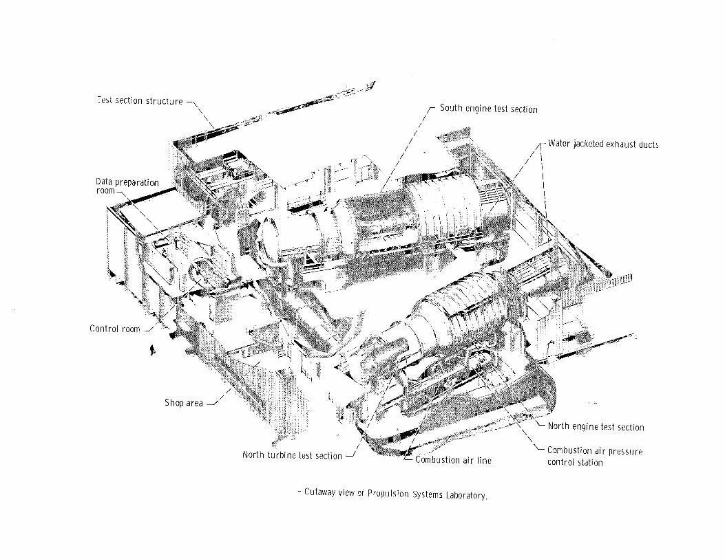
Test section structure ~ r South engine test section"
"- / /
/ " / 1\ Water jacketed exhaust ducts
/ /\II
\
\ \
Control room
Shop area -.//
North engi ne test secti on
/ Combustion air pressure North turbine test section ---.I control stati on
- Cutaway view of Propulsion Systems Laboratory.

NASA C-79-4008

C-68791