fabrication and properties of … b. rejab, mr. zulkarnian b. ... understanding and financial...
TRANSCRIPT

FABRICATION AND PROPERTIES OF
TRANSPARENT, CONDUCTIVE AND FLEXIBLE
MULTI-WALLED CARBON NANOTUBES
(MWCNTS)/EPOXY COMPOSITE FILM
SAW LIAN NA
UNIVERSITI SAINS MALAYSIA
2012

FABRICATION AND PROPERTIES OF TRANSPARENT, CONDUCTIVE
AND FLEXIBLE MULTI-WALLED CARBON NANOTUBES
(MWCNTS)/EPOXY COMPOSITE FILM
by
SAW LIAN NA
Thesis submitted in fulfillment of the requirements
for the degree of
Master of Science
March 2012
i
ACKNOWLEDGEMENTS
First and foremost, I would like to express special thanks to Prof. Ahmad
Fauzi b. Mohd. Noor, Dean of School of Materials & Mineral Resources Engineering
(SMMRE), Universiti Sains Malaysia (USM), Penang, Malaysia, for offering me the
opportunity to explore the wonderful nanoscale world. I would also like to express
my sincere gratitude to my main supervisor, Ir. Associate Prof. Dr. Mariatti bt. Jaafar
@ Mustapha, programme chairman of material engineering, USM, for her constant
guidance and encouragement which is indispensable for me to carry out this graduate
work. She showed me how to deal with conflicts and difficulties in life. Besides that,
she put a lot of extra efforts to develop my communication skills ranging from
writing to presentation. I am extremely thankful to her for sparing her valuable time
and going through my thesis and making useful corrections and suggestions. Without
her constant support, it would have been really difficult to finish my M.Sc project. I
would like to thank my first co-supervisor Dr. Azura bt. A. Rashid for her comments
about material arrangement at the early stages of my studies. I would like to extend
my thanks to my second co-supervisor Associate Prof. Dr. Azizan b. Aziz, deserves
my deepest thanks for inviting me to his lab, giving me unconditional support and
advice throughout my graduate work.
Moreover, I would like to thank all academic and technical staffs of the
(SMMRE) particularly, Mrs. Fong Lee Lee, Mrs. Hasnah bt. Awang, Mrs. Haslina bt.
Zulkifli, Mr. Mohd. Faizal b. Mohd. Kassim, Mr. Abdul Rashid b. Selamat, Mr.
Mohd. Azam b. Rejab, Mr. Zulkarnian b. Hasbolah, Mr. Mokhtar b. Mohamad, Mr.
Mohammad b. Hasan, and Mr. Mohd. Suhaimi b. Sulong for teaching me regarding

ii
the lab procedures and method techniques and always being open to suggestions and
discussions. Special thanks to Mr. Gnanasegaran A/L N. B. Dorai for supporting me
on various ways in completion of my M.Sc thesis work.
I would like to express my deepest gratitude to my family who has
encouraged me so much in my life and helped me become the person that I am today.
They have showered me with love, kindness, care and their encouragement,
understanding and financial supports, especially during the hard time in my life.
Their love and support over the years have enabled me to cross the finish line.
I express my sincere thanks to all my friends including Chua Tze Ping, Tay
Hong Kang, Kenneth Kong Theam Soon, Sam Sung Ting, Norkhairunnisa bt.
Mazlan, Lee See Yau, Nurulizzati bt. Mohd. Shukri and Norfadhilah bt. Ibrahim for
their advice and motivation and their encouragement and kind assistance throughout
the work. The warm support of all my friends enabled me to complete this thesis and
have a wonderful time along the way.
At the ends, I highly acknowledge the financial support from the Short Term
Grant, Research University Postgraduate Research Grant Scheme under Universiti
Sains Malaysia, and support from the National Science Fellowship Research
Scholarship under the auspices of the Ministry of Science, Technology, and
Innovation.
A special thank to my beloved mother, brother, sisters and Chee Chee Weng.

iii
TABLE OF CONTENTS
Page
ACKNOWLEDGEMENTS
ii
TABLE OF CONTENTS iv
LIST OF TABLES
viii
LIST OF FIGURES
ix
LIST OF PLATES
xi
LIST OF ABBREVIATIONS
xii
LIST OF SYMBOLS
xvi
LIST OF APPENDICES
xvii
LIST OF SEMINAR AND EXHIBITION
xviii
ABSTRAK
xix
ABSTRACT
xx
CHAPTER 1 – INTRODUTION
1
1.1 Introduction
1
1.2 Problem Statement
2
1.3 Research Objectives
3
1.4 Organization of Thesis
3
CHAPTER 2 – LITERATURE REVIEW
5
2.1 Introduction
5
2.2 Nanocomposites
5
2.2.1 Silicon Dioxide
9
2.2.2 Clay 9

iv
2.2.3 Carbon Nanotubes
10
2.3 Thin Film Nanocomposites
11
2.4 CNTs/Thin Film Nanocomposites
13
2.4.1 Fabrication of Flexible CNTs TCFs Nanocomposite
15
2.4.2 Properties of Flexible CNTs TCFs Nanocomposite
17
2.4.3 Applications of Flexible CNTs TCFs Nanocomposite
20
2.5 MWCNTs/Thin Film Nanocomposites
23
2.5.1 MWCNTs/Thermoplastic Thin Film Nanocomposites
24
2.5.2 MWCNTs/Thermoset Thin Film Nanocomposites
26
2.6 MWCNTs/Epoxy Thin Film Nanocomposites
32
CHAPTER 3 – MATERIALS AND METHODS
35
3.1 Materials
35
3.1.1 Matrix System
35
3.1.2 Multi-wall Carbon Nanatubes (MWCNTs)
36
3.2 Experimental Methods
36
3.2.1 Stage I: Different Epoxy-Hardener-Ratio System
Preparation
37
3.2.2 Stage II: L-MWCNTs/Epoxy and S-MWCNTs/Epoxy
Thin Film Nanocomposites Preparation
39
3.3 Characterization of Epoxy System and MWCNTs/Epoxy
Thin Film Nanocomposites
39
3.3.1 Field Emission Scanning Electron Microscopy
(FESEM)
40
3.3.2 Transmission Electron Microscopy (TEM)
40
3.3.3 Light Transmittance of MWCNTs in Epoxy
Thin Film Nanocomposites
40

v
3.3.4 Dispersion of MWCNTs in Epoxy Thin Film
Nanocomposite
41
3.3.5 Tensile Testing
41
3.3.6 Thermogravimetry Analysis (TGA)
42
3.3.7 Fourier Transform Infrared Spectrometry (FTIR)
42
3.3.8 Dynamic Mechanical Analysis (DMA)
42
3.3.9 Thermal Conductivity Measurement
43
3.3.10 Electrical Conductivity Measurement
43
CHAPTER 4 – RESULTS AND DISCUSSION
45
4.1 Introduction
45
4.2 Characterization of Different Epoxy-To-Hardener-Ratios System
45
4.2.1 Flexibility and Bendability Properties of Epoxy
Systems
45
4.2.2 Tensile properties of Epoxy Systems
47
4.2.3 Dynamic Mechanical Properties of Epoxy Systems
51
4.2.4 Fracture Surface Morphology
53
4.2.5 Fourier Transform Infrared (FTIR) Analysis
55
4.3 Characterization of L-MWCNTs/Epoxy and S-MWCNTs/Epoxy
Thin Film Nanocomposites
59
4.3.1 Surface Morphology of L-MWCNTs and S-MWCNTs
59
4.3.2 Elemental Analysis of L-MWCNTs and S-MWCNTs
by Energy Dispersive Spectroscopy (EDS)
62
4.3.3 Electrical conductivity of L-MWCNTs/Epoxy and
S-MWCNTs/Epoxy Thin Film Nanocomposites
65
4.3.4 Light Transmittance of L-MWCNTs/Epoxy and
S-MWCNTs/Epoxy Thin Film Nanocomposites
66
4.3.5 Optical transmittance of L-MWCNTs/Epoxy and
S-MWCNTs/Epoxy Thin Film Nanocomposites
68

vi
4.3.6 Dispersion Analysis L-MWCNTs/Epoxy and
S-MWCNTs/Epoxy Thin Film Nanocomposites
69
4.3.7 Fracture Surface Morphology of L-MWCNTs/Epoxy
and S-MWCNTs/Epoxy Thin Film Nanocomposites
71
4.3.8 Tensile properties L-MWCNTs/Epoxy and
S- MWCNTs/Epoxy Thin Film Nanocomposites
72
4.3.9 Dynamic Mechanical Properties of L-MWCNTs/Epoxy
and S-MWCNTs/Epoxy Thin Film Nanocomposites
75
4.3.10 Thermal Stability of L-MWCNTs/Epoxy and
S-MWCNTs/Epoxy Thin Film Nanocomposites
77
4.3.11 Thermal Conductivity of L-MWCNTs/Epoxy and
S-MWCNTs/Epoxy Thin Film Nanocomposites
80
4.3.12 Comparison of sheet resistance and transmittance of
L-MWCNTs/Epoxy and S-MWCNTs/Epoxy
Thin Film Nanocomposites with Previous Works
81
CHAPTER 5 - CONCLUSIONS AND RECOMMENDATIONS
83
5.1 Conclusions
83
5.2 Recommendations for Further Research Works
84
REFERENCES
85
APPENDICES

vii
LIST OF TABLES
Page
Table 3.1 The typical properties of D.E.R 331 epoxy matrix and
hardener type D-230
35
Table 3.2 Two types of MWCNTs specifications 36
Table 4.1 Tensile properties of the epoxy thin films as a function
of the epoxy-to-hardener ratios (System A and B)
48
Table 4.2 IR characteristic bands of uncured epoxy resin and
System A and System B
56
Table 4.3 EDS analysis data on the different types of MWCNTs 64
Table 4.4 Tensile properties of neat epoxy with different contents
of MWCNTs/epoxy thin film nanocomposites
74
Table 4.5 Thermal properties of neat epoxy with different
contents of MWCNTs/epoxy thin film nanocomposites
79
Table 4.6 Thermal conductivity of neat epoxy and with different
contents of MWCNTs/epoxy thin film nanocomposites
80
.

viii
LIST OF FIGURES
Page
Figure 2.1 A comparison of particle and matrix interaction in
nanocomposites and microcomposites
8
Figure 2.2 The polymer matrix molecular arrangement for
thermoplastic
24
Figure 2.3 The polymer matrix molecular arrangement for
thermoset
27
Figure 2.4 The characteristic group structures for epoxy resin 29
Figure 2.5 The commercially used of diglycidyl ether of bisphenol
A (DGEBA)
30
Figure 2.6 The polyaddition curing reaction of epoxy-1-propyl
phenyl ether/polyamines system
31
Figure 2.7 The different network formation of difunctional
epoxide and tetrafunctional curing agent
32
Figure 3.1 Micrograph of as-received MWCNTs at a
magnification of 20 KX (a) S-MWCNTs (b) L-
MWCNTs
36
Figure 3.2 The specimen preparation method 38
Figure 3.3 The specimen fabrication process by using hot-pressing
technique, (a) suspension in between two hot press
plates, (b) application of pressure and (c)
MWCNTs/epoxy thin film nanocomposites
39
Figure 3.4 Schematic of specimens and sensor for the Hot Disk 43
Figure 4.3 Stress-strain curves of System A and System B 49
Figure 4.4 The rigid macromolecular structure of reaction between
epoxides and polyamine
50
Figure 4.5 Storage modulus and tan delta curves for different
epoxy-to-hardener ratio systems
52
Figure 4.6 Loss modulus curves for different epoxy-to-hardener
ratio systems
53

ix
Figure 4.9 FTIR spectra of uncured epoxy resin and different
epoxy-to-hardener systems at the bands of 914 cm-
1with a shoulder at 862 cm
-1
57
Figure 4.10 FTIR spectra of uncured epoxy resin and different
epoxy-to-hardener systems at the band of 3054 cm-1
57
Figure 4.11 FTIR spectra of uncured epoxy resin and different
epoxy-to-hardener systems
58
Figure 4.13 EDS analysis on L-MWCNTs (a) Spot taken for EDS
analysis and (b) EDS spectrum
63
Figure 4.14 EDS analysis on S-MWCNTs (a) Spot taken for EDS
analysis and (b) EDS spectrum
64
Figure 4.15 Electrical conductivity as a function of MWCNTs
contentsfor L-MWCNTs and S-MWCNTs
65
Figure 4.16 UV-visible spectra of thin film nanocomposites
containing different MWCNTs contents
68
Figure 4.20 Young’s modulus as a function of MWCNTs contents
for L-MWCNTs and S-MWCNTs
74
Figure 4.21 Tensile strength as a function of MWCNTs contents for
L-MWCNTs and S-MWCNTs
75
Figure 4.22 Strain at break as a function of MWCNTs contents for
L-MWCNTs and S-MWCNTs
75
Figure 4.23 Storage modulus and loss factor tan δ as a function of
temperature for thin film nanocomposites with different
MWCNTs contents (a) L-MWCNTs, and (b) S-
MWCNTs
77
Figure 4.24 TGA as a function of temperature for thin film
nanocomposites with different MWCNTs contents for
L-MWCNTs and S-MWCNTs
79
Figure 4.25 Thermal conductivity of thin film nanocomposites as a
function of MWCNTs contents for L-MWCNTs and S-
MWCNTs
81
Figure 4.26 Comparison of normalize sheet resistance (Ω/sq)
versus normalized transparency (%) at wavelength
550nm between the current study and those taken from
the literature
82

x
LIST OF PLATES
Page
Figure 4.1 Optical photographs of transparent, conductive flexible
thin films with different epoxy-to-hardener ratios: (a)
100:32 (b) 100:45 (c) 100:60
46
Figure 4.2 Optical photographs of dumbbell specimens with
different epoxy-to-hardener ratios: (a) 100:32 (b)
100:45 (c) 100:60
46
Figure 4.7 Tensile fracture surface features of System A: a) the
mirror zone; b) the transition zone; c) the final
propagation zone
54
Figure 4.8 The fracture surface of System B dominated by a very
large tear zone
54
Figure 4.12 Typical FESEM micrographs of as-received CNTs
exhibiting net-like arrays (a) L-MWCNTs, (b) S-
MWCNTs, (c) L-MWCNTs with outer diameter of 26
nm, and (d) S-MWCNTs with outer diameter of 76 nm.
Typical TEM images of (e) L-MWCNTs and (f) S-
MWCNTs
59
Figure 4.17 Optical photographs of transparent thin film
nanocomposites containing (a) L-MWCNTs (b) S-
MWCNTs of MWCNTs contents (i) 0.04 wt% (ii) 0.10
wt% (iii) 0.50 wt%
69
Figure 4.18 Optical micrographs MWCNTs/epoxy thin film
nanocomposite specimens containing 0.10 wt% (a) L-
MWCNTs and (b) S-MWCNTs; and 0.50 wt% (c) L-
MWCNTs and (d) S-MWCNTs
70
Figure 4.19 FESEM micrograph of fracture surface of
MWCNTs/epoxy thin film nanocomposite specimens
containing different MWCNTs contents:- (a) and (b)
0.10 wt% L-MWCNTs; (c) and (d) 0.10 wt% S-
MWCNTs, (e) and (f) 0.50 wt% L-MWCNTs, (g) and
(h) 0.50 wt% S-MWCNTs
71

xi
LIST OF ABBREVIATIONS
Al Aluminium
AFM Atomic force microscopy
AHEW Amine Hydrogen Equivalent Weight
Ca Calcium
CNTs Carbon nanotubes
DC Direct Current
DGEBA Diglycidyl Ether of Bisphenol A
DMA Dynamic mechanical analysis
DNA Deoxyribonucleic acid
DWCNTs Double wall carbon nanotubes
EDS Energy dispersive spectroscopy
EEW Epoxide equivalent weight
EPD Electrophoretic deposition
ESC Electrostatic charge
FESEM Field emission scanning electron microscope
FPD Flat panel displays
FTIR Fourier transform infrared spectroscopy
ITO Indium tin oxide
IZO Indium-doped zinc oxide
K Potassium
L-MWCNTs High aspect ratio MWCNTs
LB Langmuir-Blodgett
LCD Liquid crystal display

xii
MAPLE Matrix-assisted pulsed-laser evaporation
Mg Magnesium
MMT Montmorillonite
MWCNTs Multi wall carbon nanotubes
Na Sodium
NH2 Amino group
N-H Secondary amine unit
Ni Nickel
O Oxygen
OH Hydroxyl unit
OLED Organic light-emitting diodes
PC Polycarbonate
PCBM Phenyl-C61-butyric acid methyl ester
PE Polyethylene
PEO Polyethylene oxide
PET Polyethylene terephthalate
PI Polyimide
PLD Pulsed-laser deposition
PMMA Polymethyl methacrylate
PNCs Polymer nanocomposites
PVA Polyvinyl alcohol
RR-P3HT Regioregular-poly-3-hexylthiophene
S Sulphur
SSA Specific surface area
SWCNTs Single wall carbon nanotubes

xiii
S-MWCNTs Low aspect ratio MWCNTs
T Transmittance
TCFs Transparent conductive thin films
TCO Transparent conducting oxides
TEM Transmission electron microscopy
TFPVs Thin film photovoltaics cell
TGA Thermogravimetric analysis
TiO2 Titanium dioxide
TV Television
UV-vis Ultraviolet–visible
XMS X-ray Microanalysis System
TG/DTA Thermo Gravimetry/Differential Thermal Analyzer
0-D 0-Dimensional
1-D 1-Dimensional
2-D 2-Dimensional
3-D 3-Dimensional
cPs Centipoises
cm-1
reciprocal centimeters
g/eq gram per equivalent
g/ml gram per millilitre
GPa Giga Pascal
Hz hertz
kHz kilohertz
kN Kilo Newton
kV Kilovolt
xiv
meq/g Milliequivalent per gram
m2/g square meters per gram
mPa.s milli Pascal second
MPa Mega Pascal
mm2
square millimeter
mg milligram
min Minute
mm Millimetre
nm Nanometre
Pa.s Pascal second
S/cm Siemens per centimeter
t Thickness
TPa Tera Pascal
μm Micrometre
o Degree
°C Degree Celsius
Ω/sq ohms per square
%wt weight percent

xv
LIST OF SYMBOLS
d Thickness
D Diameter
E Young’s modulus
E’ Storage modulus
F Load
L Length
δ Loss factor
Td Onset Temperature of thermal decomposition
T5 Temperature at 5 % weight loss
σdc DC conductivity
Rs Sheet resistance
σop Optical conductivities
σ Electrical conductivity
pv Volume resistivity
Rv Volume resistance
σ Tensile strength
Tg Glass transition temperature
ε Strain at break
% Percentage
C60 Buckyball
λ Lambda
xvi
LIST OF APPENDICES
APPENDIX A: The Volume Conductivity Formulation Derivation
APPENDIX B: Stoichiometric Calculation

xvii
LIST OF SEMINAR AND EXHIBITION
Seminar
1. Mariatti, M., Saw, L.N. (2010). Tensile and Electrical Properties of
Thin, Flexible and Transparent Multi-walled Carbon Nanotube/Epoxy
Composites In: Seminar Kebangsaan Aplikasi Sains & Matematik
(SKASM) sempena Simposium Kebangsaan Sains Matematik ke-18
(SKSM 18), Johor Bahru, Malaysia, 8th -10
th December 2010, pp.1-6.
Exhibition
1. Mariatti, M., Foo, Y. L. E., Saw, L.N., Voo, T.V., & Lim, C. S. (2011)
A novel flexible epoxy thin film composites. In: 22nd
International
Invention, Innovation & Technology Exhibition (ITEX 2011), Kuala
Lumpur, Malaysia, 20th -22
th May 2011.

xviii
FABRIKASI DAN SIFAT FILEM KOMPOSIT NANOTIUB KARBON
DINDING BERBILANG/EPOKSI LUTSINAR, KONDUKTIF DAN MUDAH
LENTUR
ABSTRAK
Dalam kajian ini filem nipis nanokomposit epoksi yang lutsinar optikal,
konduktif dan mekanikal mudah lentur dihasilkan. Kajian ke atas sifat bagi
perbezaan nisbah epoksi/agen pematangan, dua jenis nisbah aspek nanotiub karbon
dinding berbilang (MWCNTs) dan pembebanan MWCNTs telah dijalankan.
Keputusan ujian tegangan dan analisis dinamik mekanik (DMA) menunjukkan sifat
sistem epoksi bergantung kepada nisbah epoksi-kepada-agen pematangan. Ianya
menunjukkan spesimen dengan nisbah epoksi-kepada-agen pematangan 100: 45
(Sistem A) mempamerkan kekuatan tegangan, modulus Young dan modulus
simpanan yang lebih tinggi berbanding dengan nisbah epoksi-kepada-agen
pematangan 100: 60 (Sistem B). Dua jenis MWCNTs yang berlainan nisbah aspek
dan pembebanan disebarkan dalam resin epoksi melalui proses ultrasonic dan
diacuan mampat untuk menghasilkan filem nipis epoksi nanokomposit. Keputusan
menunjukkan nanokomposit yang mengandungi MWCNTs dengan nisbah aspek
yang rendah (S-MWCNTs) mempamerkan kekonduksian elektrik yang lebih bagus
berbanding dengan nisbah aspek yang lebih besar (L-MWCNTs). Modulus Young,
kekuatan tegangan dan kestabilan terma dalam filem nipis S-MWCNTs
nanokomposit lebih tinggi jika dibandingkan dengan L-MWCNTs. Ini disebabkan
penyebaran S-MWCNTs yang lebih bagus dalam resin epoksi. Rintangan helaian
serendah 100 Ω/sq dengan lutsinar optikal lebih kurang 60 % pada 550 nm dicapai
dengan penambahan MWCNTs ke dalam epoksi.
xix
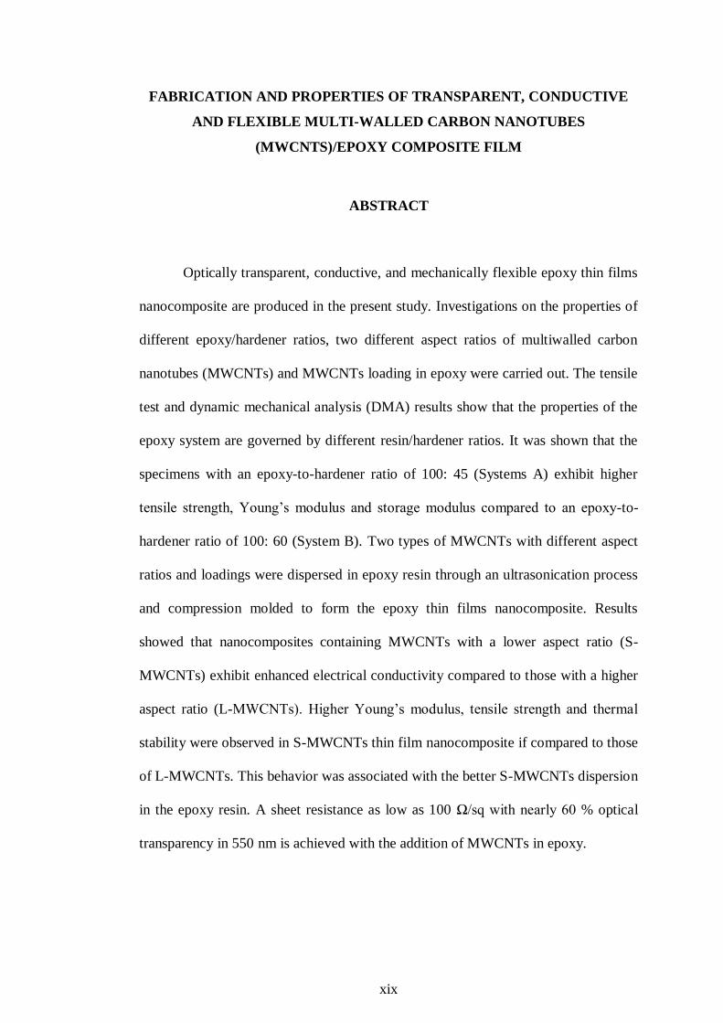
FABRICATION AND PROPERTIES OF TRANSPARENT, CONDUCTIVE
AND FLEXIBLE MULTI-WALLED CARBON NANOTUBES
(MWCNTS)/EPOXY COMPOSITE FILM
ABSTRACT
Optically transparent, conductive, and mechanically flexible epoxy thin films
nanocomposite are produced in the present study. Investigations on the properties of
different epoxy/hardener ratios, two different aspect ratios of multiwalled carbon
nanotubes (MWCNTs) and MWCNTs loading in epoxy were carried out. The tensile
test and dynamic mechanical analysis (DMA) results show that the properties of the
epoxy system are governed by different resin/hardener ratios. It was shown that the
specimens with an epoxy-to-hardener ratio of 100: 45 (Systems A) exhibit higher
tensile strength, Young’s modulus and storage modulus compared to an epoxy-to-
hardener ratio of 100: 60 (System B). Two types of MWCNTs with different aspect
ratios and loadings were dispersed in epoxy resin through an ultrasonication process
and compression molded to form the epoxy thin films nanocomposite. Results
showed that nanocomposites containing MWCNTs with a lower aspect ratio (S-
MWCNTs) exhibit enhanced electrical conductivity compared to those with a higher
aspect ratio (L-MWCNTs). Higher Young’s modulus, tensile strength and thermal
stability were observed in S-MWCNTs thin film nanocomposite if compared to those
of L-MWCNTs. This behavior was associated with the better S-MWCNTs dispersion
in the epoxy resin. A sheet resistance as low as 100 Ω/sq with nearly 60 % optical
transparency in 550 nm is achieved with the addition of MWCNTs in epoxy.

1
CHAPTER 1
INTRODUCTION
1.1 Introduction
The invention of the optically transparent, conductive and mechanically
flexible electronic device could open a promising door for the next generation
optoelectronic technology. Since the 1960s, the conducting indium tin oxide (ITO)
has known as a key ingredient to offer electrical conductivity onto the optical
transparent glass or polymeric thin film nanocomposites (Deshpande et al., 2008).
However, the choice of this transparent conducting oxide is not promising. ITO thin
film nanocomposites have shown several drawbacks, including high production costs
and the scarcity of indium (Castro et al., 2009; Chan and Roussel, 2007).
Furthermore, their rigidity made ITO coatings on flexible substrates performs
reliability concern in certain applications (Chan and Roussel, 2007, Xu et al., 2009).
As a consequence, new materials as replacements have been studied in the
development of the flexible optical transparent conductive thin films (TCFs)
nanocomposite. Carbon nanotubes (CNTs) are acknowledged as good replacements
for ITO in TCFs nanocomposite fabrication (Chan and Roussel, 2007). The potential
applications for TCFs nanocomposite range from transparent electrical shielding
products to flexible video displays, including transparent monitors, touch screen
panels, and laptop screens (Chan and Roussel, 2007).
CNTs/polymer thin film nanocomposites are commonly referred as potential
materials to produce the TCFs nanocomposites. CNTs/polymer thin film
nanocomposites combine the advantages of CNTs and polymeric materials, in which

2
CNTs exhibit higher strength (~100 times stronger than steel), modulus (about 1TPa)
and thermal conductivity (about twice as high as diamond), excellent electrical
capacity (1000 times higher than copper), thermal stability (2800°C in vacuum) and
electrical properties (in the order of 103–10
4 S/cm) (Liao et al., 2004; Zhou et al.,
2008). On the other hand, polymers present good flexibility, transparency, easy
processing, and low cost (Peng, 2008). Besides that, CNTs have the superior
combination of environmental stability, flexibility and high transparency at the
visible wavelength characteristic compared to the conventional TCFs nanocomposite
in the display industries (Gu and Swager, 2008; Saran et al., 2004). Furthermore, the
CNTs were commonly deposited by spray coating and printing from suspension
instead of the costly vacuum process (Gu and Swager, 2008). Thus, CNTs gives a
great perspective for future flexible displays in the development of TCFs
nanocomposite which more reliable in this application than the amorphous ITO.
Compare to various types CNTs, multi wall carbon nanotubes (MWCNTs) has been
widely used due to their lower price than single wall carbon nanotubes (SWCNTs)
and double wall carbon nanotubes (DWCNTs). It is reported to show the highest
potential of thermal and electrical conductivity enhancements in CNTs-based
nanocomposites (Gojny et al., 2006).
1.2 Problem Statement
Fabrication of high quality, flexible, conductive, and transparent thin films
remain challenging. Most of the previous efforts on these materials have focused on
the properties of CNTs/thermoplastic thin film nanocomposites, such as polymethyl
methacrylate (PMMA) and polyimide (PI) (Sellinger et al., 2006; Wu et al., 2010).
The unique properties of thermoset polymers are excellent thermal stability and

3
optical properties, low viscosity and shrinkage, superiority in adhesion properties,
good mechanical strength, erosion protection, and processing versatility. After
realizing those unique properties, researchers have begun to carry out an increasing
number of studies on thin films produced from epoxy systems (Shin et al., 2009a).
This rigid epoxy thin film provides good thermal properties and mechanical strength,
but it can only be positioned in two dimensions (Li et al., 2008a). Demand on
flexible electronic technologies for a substrate which is able to fold and bent in three
dimensions has increased. It is reported that this flexible substrate can decrease the
failure under mechanical bending by absorbing internal stress, which is generated
during processing (Li et al., 2008a). This will increase the reliability of the thin film
in roll-to-roll processing and reducing manufacturing costs.
1.3 Research Objectives
The objectives of this research work are:
1. To determine the effect of the different ratio of epoxy-to-hardener on the
properties of transparent epoxy thin films.
2. To investigate the effect of different types of MWCNTs and contents on the
transparency, electrical conductivity and tensile properties of the thin film
nanocomposite materials.
1.4 Organization of Thesis
The thesis consists of five chapters. Chapter 1 contains an introduction of the
TCFs nanocomposite, the project problem statements, research objectives and the
arrangement of the thesis. Chapter 2 reports on a literature review that discusses on
chemical structure and properties of CNTs, on thin film, TCFs nanocomposite and

4
CNTs in TCFs nanocomposite application. Chapter 3 describes the materials and
experimental procedures details regarding the design, the optimization of the
fabrication method and characterization techniques of epoxy thin film and
MWCNTs/epoxy thin film nanocomposites. The results and discussion of the
findings, including the surface morphology, mechanical electrical, thermal properties
of the MWCNTs/epoxy thin film nanocomposites, are presented in Chapter 4.
Chapter 5 is the final chapter that provides a foundation for the conclusions drawn
out from the results. Moreover, the observations and suggestions for the future work
to complement this research also presented.

5
CHAPTER 2
LITERATURE REVIEW
2.1 Introduction
In this chapter, the development of the optical flexible CNTs transparent
conductive thin films (TCFs) nanocomposite is discussed. Various techniques
fabrication, properties and application of optical flexible CNTs TCFs nanocomposite
are also introduced. Finally, the development of the MWCNTs/epoxy thin film
nanocomposites was explored as well.
2.2 Nanocomposites
Nanomaterials are typically categorized as 0-D (nanoparticles), 1-D
(nanowires, nanotubes, and nanorods), 2-D (nanofilms and nanocoatings) or 3-D
(bulk) (Ashby et al., 2009). Nanocomposites are nanomaterials that are created by
introducing nanofillers into a macroscopic specimen material (Li et al., 2009). After
adding nanofillers to the matrix material, the resulting nanocomposites may exhibit
drastically enhanced properties (Li et al., 2009). Moreover, Michler, (2008) reported
that the nanoscale reinforcement has an observable effect on the properties and the
stability of polymers. For example, adding CNTs tends to improve the electrical and
thermal conductivity. Other kinds of nanofillers may result in enhanced optical
properties, dielectric properties, or mechanical properties such as stiffness and
strength (Li et al., 2009). This has demonstrated a new class of composites, the
polymer nanocomposites (PNCs) (Michler, 2008). PNCs are polymers
(thermoplastics, thermosets or elastomers) that have been reinforced with small
quantities (less than 5% by weight) of nano-sized fillers having high aspect ratios

6
with one dimension in the range of 0.1–100 nm. These PNCs are generally
lightweight, require low filler content, and are often easy to process. They provide
property enhancements extending orders of magnitude beyond those realized with
traditional composites (Miller, 2008).
The development in PNCs technologies has been carried out as new classes
of nanoscale fillers continue to emerge. By using nanofillers in a polymer matrix
and achieving extraordinary properties is an area of active interest in nanocomposite
technology (Kotsilkova & Pissis, 2007). Depending on the properties to be modified,
the most suitable nanofiller have to be chosen to obtain the desired effect (Bellucci et
al., 2010).
Nanofiller-filled polymers provide advantages over micron-filled polymers
because they provide better resistance to degradation, and improvement in thermo-
mechanical properties without causing a reduction in dielectric strength (Kozako et
al., 2004; Ash et al., 2002). For example, Nelson and Fothergill, (2004) documented
that an increase in dielectric strength and a reduction in space charge of nano-
titanium dioxide (TiO2) filled epoxy resin over micron size TiO2 filled epoxy
composites. These dielectric properties improvements could be due to several factors:
(i) the large surface area of nanofillers altered the polymer behavior, (ii) polymer
morphology changed due to the surfaces of particles, (iii) decrease in size of the
particles causes the reduction of the internal field, (iv) change of the space charge
distribution, and (v) a scattering mechanism (Ash et al., 2004; Ma et al., 2005;
Nelson et al., 2002; Roy et al., 2005). According to Kotsilkova and Pissis, (2007)
nanocomposites can exhibit novel and significantly improved properties not just

7
because of the small nanoscale size of the filler but also the chemical processes that
occur at the nanofiller-matrix interface. Nanofillers in the polymer matrix showed
two differences compared with conventional fillers (in the micron range) in polymer
composites (Michler, 2008). These differences are due to the transition from micro-
particles to nanofillers lead to a number of changes in physical properties. Firstly,
the sizes of the nanofillers are comparable to the radius of gyration of the
macromolecules in the polymer matrix, so that the morphological development of the
polymer matrix can be substantially affected by the dispersed nanofillers
(morphology under constraint condition). Secondly, the nanofillers have a high
surface area-to-volume ratio, particularly when the size decreases below 100 nm and
hence their properties are dominant by surfaces rather than bulk (Hosokawa et al.,
2007).
This high surface area to volume ratio means that for the same particle
content, nanocomposites will have a much greater interfacial area than
microcomposites. Since this interaction zone is much more extensive for
nanocomposites than for microcomposites, it can have a significant impact on
properties as shown in Figure 2.1 (Peukert et al., 2003). As a consequence, the
amount of modified polymer interfaces relative to the total volume will be
significantly increased which corresponding to the transition from a polymer matrix
material to a quasi-polymer interfacial material (Michler, 2008). For example,
depending upon the strength of the interaction between polymer and particle, the
interaction zone can have a higher or lower mobility than the bulk material and result
in an increase or decrease in glass transition temperature (Ash et al., 2002). Roy et al.
(2005) stated that the dramatic improvement in electrical properties of the

8
nanocomposite was affected by the interactions between the nanoparticles surface
and the matrix. They found that covalent bonding between the nanofillers and the
matrix increases the temperature at which the breakdown strength decreases. The
increase in the interfacial region in nanocomposites creates a zone of altered polymer
properties, which reduces the dielectric permittivity of nanocomposites. The highest
voltage endurance occurs for composites with strong covalent bonding between the
matrix and the filler. Additionally, the nanofillers have dimensions below the critical
wavelength of light makes them transparent, a property that makes them very
attractive for applications in packaging, cosmetics, and coatings.
Figure 2.1: A comparison of particle and matrix interaction in nanocomposites and
microcomposites (Li et al., 2009).
The commonly dispersed nanofillers in polymer matrices include: Silicon
oxides (silica), Nanoclays (montmorillonite, hectorite, etc.), CNTs, etc. (Bellucci et
al., 2010). Like most nanofiller, the nanoclay and silica were used to improve the
barrier properties, modulus, mechanical properties of most composites, particularly
stiffness and tensile strength. However, these types of nanofillers were unsuitable for
the application that electrical conductivity was needed such as conductive plastics,
nano-electronics. Thus, CNTs become the common nanofiller used to increase the
conductive properties of the polymeric matrix.
Interaction
zone
Nano-sized
particle Interaction
zone
Micron-sized
particle
9
2.2.1 Silicon Dioxide
Silicon dioxide is also known as silicon (IV). It is commonly called silica and
become popular not just because of its hardness but also it can be easily found in
nature as sand or quartz mineral (Whelan, 1994). The silica appears like a quasi-
spherical shape with the diameter ranging from a few nanometers to 100 nm and thus
the aspect ratio is close to 1. It can be used as filler in both thermoplastic and
thermosetting polymer matrix with content in the range of 1–20 wt%. A compatible
material is needed for better nanofillers dispersion. However, it depends on which
type of polymer matrix (hydrophilic/hydrophobic) used in preparing the composite
materials.
2.2.2 Clay
Clay is commonly called layered silicates which belong to the structure
family known as phyllosilicates. This crystal structure consists with the prevailingly
Si and O (base formula SiO4) to form a tetrahedral structure (Rabová, 2009). Since
each tetrahedral has an excess negative net electrical charge, the silicate must have
that charge balanced by some metal cations to achieve an electrically neutral
compound. The alkali or alkaline earth metals like magnesium (Mg), kalium (K),
sodium (Na) and calcium (Ca) have purposed to bind together the different silicate
tetrahedral structures. Montmorillonite (MMT), hectorite and saponite are the most
common used of layered silicates in nanocomposites (Sinha Ray and Okamoto,
2003). These materials are widely used as electrical insulating materials due to their
high aspect ratio (up to 1,000) and peculiar intercalation/exfoliation capability
(Bellucci et al., 2010).

10
2.2.3 Carbon Nanotubes
After the report on the discovery of ― buckyball ‖, fullerence C60 molecule by
Kroto et al. in 1985 there is huge increase in interest in their science. The C60
molecule exists in the discrete molecular form and consists of a hollow spherical
cluster of sixty carbon atoms (Kakani & Kakani, 2006). Each molecule is composed
of groups of carbon atoms that are bonded to one another to form both hexagon and
pentagon geometrical configuration (Kakani & Kakani, 2006). In 1991, Sumio Iijima,
a Japanese researcher working in NEC Laboratory explored a method to make
fullerences using cathode arc discharge. He unexpectedly discovered a whole new
class of fullerence called CNTs.
Since the discovery of CNTs, lots of researches have greatly stimulated this
novel material in the field of physical, chemistry and material science. CNTs are
cylindrical nanostructures with a diameter ranging from 1nm to several nanometers,
and a length of tens of micrometers. They are made of graphene sheets wrapped into
a hollow cylinder and capped by fullerence like structures (Ye and Sheu, 2007).
CNTs are considered as a unique material with a lot of unusual properties such as
hard and heat-conductive as diamonds, and many times stronger than steel at one
sixth of the density. Unlike steel, nanotubes are flexible and elastic, bouncing back to
their original shape after being bent or stretched. Besides that, it can be electrically
conductors, insulator and semiconductor (Shim et al., 2008).
CNTs consisting of single and multiple concentric graphene cylinders such as
single wall (SWCNTs), double-wall (DWCNTs), and multiwall (MWCNTs),
depending on the shell number and how the graphene sheet rolled up itself

11
(Hernández-Pérez et al., 2008; Li et al., 2008b). SWCNTs possess a cylindrical
nanostructure with a high aspect ratio, formed by rolling up a single graphite sheet
into a tube. SWCNTs often capped at both ends, with outer diameters in the range
from several nanometers up to 200 nm (O'Connell, 2006). The van der Waals forces
keep the individual SWCNTs together, forming a triangular lattice with a lattice
constant of 0.34 nm. DWCNTs are another new species in the family of carbon
nanophase. They have the same small size as the SWCNTs but are stiffer and
therefore, more appropriate as mechanical sensors (Kuzmany, 2006). Although
DWCNTs are constructed from two SWCNTs with the same or different chiralities,
the electronic properties of each nanotube within DWCNTs can be different from
those of isolated SWCNTs (Banerjee et al., 2009). MWCNTs are tiny electrodes
made of carbon, metals or semiconducting materials having typical dimensions of 1-
100 nm. The MWCNTs composed of individual SWCNTs concentrically with
different diameters and separated by an interlayer distance of about 0.34 nm slightly
larger than in graphite due to curvature (Maser, et al., 2008). The length and
diameter of the most inner tubes are similar to SWCNTs, the outer diameters,
depending on the number of individual nanotubes, easily can reach values up to 20 or
30 nm (O’Connell, 2006; Maser et al., 2009). These concentric nanotubes are held
together by van der Waals bonding.
2.3 Thin Film Nanocomposites
Thin film technology is closely linked with nanotechnology, which is
becoming one of the main areas in the new-generation manufacturing and precision
engineering industries, especially in the manufacture of electronic, magnetic and
optical devices (SreeHarsha, 2006). Thin film is considered as a layer of material

12
ranging from fractions of a nanometer (monolayer) to several micrometers in
thickness (Tilman, 2010). Nowadays, there are strong requirements for the layer of
materials to be transparent, conductive and flexible. It has also become an essential
part of technologies to require both large area electrical contact and optical access in
the visible portion of the light spectrum (Liu, 2007). For example, the resistivity of
transparent conductive thin films must be made as low as possible in order to
conserve energy, power and resources. For the past decades, transparent conducting
oxides (TCO) become the only choice for the large flat screen high definition
television, flat panel displays, hand-held smart displays, thin film solar cells,
functional glass for window applications (SreeHarsha, 2006; Liu, 2007). One of the
most widely used transparent conducting oxides is ITO.
ITO causes a great interest due to its transparency (higher than 80 % in the
visible wavelength) and good electrical conductivity (Castro et al., 2009; Djaoued et
al., 1997). Apart from that, ITO also has important properties such as high infrared
reflectance, excellent substrate adherence and chemical inertness (Kim et al., 1999).
Those properties have made ITO thin film nanocomposites adopted in many
applications include plasma display panels, flat panel displays (FPD), liquid crystal
display (LCD), organic light-emitting diodes (OLED) (Lee, et al., 2008).
Nevertheless, ITO thin film nanocomposites can be prepared by many methods such
as activated reactive evaporation, chemical vapor deposition, the sol-gel process (Ota
et al., 2003; Biswas et al., 2003; Djaoued et al., 1997). However, those fabrication
techniques involve vacuum and high temperature processes which are expensive and
complicated (Chan and Roussel, 2007; Watcharotone et al., 2007). Furthermore, ITO
coatings tend to undergo severe dimensional changes after mechanical bending or

13
hammering and thermal gradient (Chan and Roussel, 2007). All these drawbacks
increase the interest for alternative material studied for ITO replacement, such as
CNTs (Kaempgen et al., 2005).
2.4 CNTs/Thin Film Nanocomposites
CNTs are chosen to replace ITO in TCFs nanocomposite fabrication due to
their ability to retain the same optical transparency and electrical conductivity
properties, which are comparable with traditional ITO thin film nanocomposites (Pei
et al., 2009). Furthermore, CNTs thin film nanocomposites exhibit comparable
flexibility and environmentally resistant to ITO thin film nanocomposites. The
carbon sources are cheaper and easy to obtain than indium; hence, CNTs become the
only potential material in TCFs nanocomposite technology for replacement of ITO
thin film nanocomposites in optoelectronic, durable transparent electrode application.
Dos Santos (2008) reported that there are two important factors that influence
the load transfer in CNTs TCFs nanocomposite. The first factor is the strong
interfacial bonding between a polymer matrix and CNTs and the second is a
homogeneous dispersion of nanotubes throughout the polymer matrix. For examples,
Ajayan et al., (2000) reported the weak interfacial bonding between the epoxy matrix
and SWCNTs resulted in low performance nanocomposites. Agglomeration of
nanotubes is reported to weaken the nanocomposite properties since agglomerated
nanofillers often behave as micro or even macroscopic defects. Kim et al., (2007)
reported that the higher surface energy of nanotubes leads to a heterogeneous
dispersion in the polymer matrix and has negative effects on the properties of the
resulting nanocomposites. Clearly, the state of dispersion of CNTs directly affects
14
the mechanical behavior of the materials (Song et al., 2005). To meet these
challenges, a few successful approaches for the homogeneous dispersion have been
explored by today researchers.
CNTs dispersion aids can be divided into five main types: (1) surfactant; (2)
polymer wrapping; (3) direct dispersion of pristine or functionalized CNTs in
organic solvent and water; (4) other dispersion aids such as DNA, protein and starch
and (5) sonication (Hu et al., 2010; Suave et al., 2009). Using surfactant is the most
widely used method for TCFs nanocomposite fabrication at high CNTs concentration.
These are due to surfactant can be easily removed by subsequent washing of thin
film after fabrication without affecting the thin film properties (Hu et al., 2010).
Polymer wrapping is another common method for CNTs dispersion, especially for
CNT PNCs applications. Polymers are potentially assembled onto pristine CNTs
through π-π stacking interactions, which preserve the CNTs intrinsic properties. For
CNTs thin film nanocomposites applications, polymer-assisted dispersion is not
preferred due to large size of polymers and the difficulty in removing the polymers
after fabrication. Some methods have been proposed to remove polymers after CNTs
thin film nanocomposites fabrication such as annealing or un-wrapping the polymers
(Hu et al., 2010). Besides that, dispersed the functionalized CNTs in water is
favorable due to the environmental friendly and biocompatible nature of water.
Functionalization in acid condition can generate enough functional groups to
facilitate the solubility of CNTs in water. However, dramatic amounts of defects are
induced and cause matrix cracking, which leads to fiber debonding during
mechanical testing (Hosur et al., 2010). Other materials have been studied for
dispersing CNTs such as DNA, protein and Nafion. DNA-assisted dispersion is of

15
particular significance due to its biological implications (Hu et al., 2010). According
to Asada et al., (2010), the DNA wrapped CNTs are completely stable without
unbound the DNA molecules. The DNA-CNTs are easily formed into uniform,
desired-density and conductive networks of individual nanotubes (Asada et al.,
2010). Centrifugation and sonication are the simple techniques that use high-
intensity acoustic energy to create well dispersed CNTs solutions. During sonication,
nanotubes entanglements are reduced. However, these techniques are reported to
damage and degrade the structure of the CNTs which in turn could eventually
shorten the length of the nanotubes (Hecht and Gruner, 2009). The sonication effect
has been evaluated by Suave et al., (2009) that tensile strength of CNTs system
increased after sonication at high amplitude for a short period of time.
2.4.1 Fabrication of Flexible CNTs TCFs Nanocomposite
Currently, several methods can be used in industrial and laboratory for TCFs
nanocomposite fabrication. The solution-based deposition methods such as spin
coating, dip-coating, slot coating, Langmuir-Blodgett (LB) and vacuum filtering are
the most reliable and cost-effective methods to fabricate CNTs TCFs nanocomposite
(Hu et al., 2010; Andrew Ng et al., 2008; Hecht and Gruner, 2009; Manivannan et
al., 2010; Woo et al., 2007). Spin coating is preferred due to its simple processes,
and it can be used directly on the substrate compared to vacuum filtration. The spin
coating involved the high-speed spinning of the substrate (Hu et al., 2010). However,
this simple solution deposition technique is hard to control the wetability on the
substrate. As a consequence, the thin film that was fabricated is non uniform and
become a problem for large production (Liu et al., 2010). This uneven thickness

16
would affect the TCFs nanocomposite electrical conductivity, transparency and
mechanical properties.
Andrew Ng et al., (2008) reported on the use of dip coating in CNTs TCFs
nanocomposite fabrication. They promoted that dip coating is scalable and become
more promising for low cost and large-scale production of transparent and
conductive coatings. The solution viscosity, concentration of the solution, the time of
dip coating, the interaction between the substrate and the dispersion and the coating
speed affect the thickness of the TCFs nanocomposite (Hu et al., 2010). However,
both sides of the substrate are coated during the dip coating, become not practical for
certain applications (Hu et al., 2010).
Slot coating is another process where a thin film (5–30 μm) of solution is
applied evenly to the substrate surface through a slot die (Hecht and Gruner, 2009).
This method yields thin films of high uniformity and high yield, and is a well known
commercial process used in roll-to-roll manufacturing. However, the conductivity of
thin films deposited by this method is limited by surfactant molecules remaining in
the thin film structure after deposition. Therefore, all unwanted solubilization agents
must be removed before processing (Hecht and Gruner, 2009).
LB is the method that needs the CNTs in hydrophobic behavior. This
hydrophobic group enables a thin film to lay on a free surface of a subphase
compound such as water (Armitage et al., 2004). This method is widely used by
researchers to fabricate high quality CNTs TCFs nanocomposite because it is easier
to control the thickness (Manivannan et al., 2010; Woo et al., 2007).

17
The vacuum filtration is also a widely used method to prepare CNTs TCFs
nanocomposite specimen. However, this method shows few drawbacks where it is
not suitable for large scale production in industrial due to the small and limited size
of the membrane filtration (Manivannan et al., 2010). De et al., (2009) in their work
develop the CNTs TCFs nanocomposite using vacuum filtration with transmittance
and sheet resistance values of T=75 % and Rs= 80 Ω/sq.
Recently, an effective approach to produce flexible CNTs TCFs
nanocomposite by a combination of electrophoretic deposition (EPD) and hot-
pressing transfer was proposed by Pei et al., (2009). The CNTs TCFs nanocomposite
obtained by this technique can achieve a sheet resistance of 220 Ω/sq and a
transparency of 81 %, which satisfy the requirements set for touch screen application
(Pei et al., 2009). It is reported that the pressing transfer lead to strong adhesion
between the CNTs thin film and the polymer substrate. Since part of the CNTs thin
film nanocomposites can be embedded into the polyethylene terephthalate (PET)
substrate, the CNTs TCFs nanocomposite displays excellent flexibility. Besides,
these EPD and hot-pressing techniques are simple, low cost, and have already been
widely used in the industry. Therefore, this approach is reported well for the
continuous production of homogeneous and large CNTs TCFs nanocomposite with
desirable performance (Pei et al., 2009).
2.4.2 Properties of Flexible CNTs TCFs Nanocomposite
CNTs thin film nanocomposites are a novel 2D structure with a mixture of
semiconducting and metallic tubes (Hu et al., 2010). CNTs thin film nanocomposites
have the collective behavior of the individual tubes and the properties arising from

18
the tube-tube interactions (Hu et al., 2010). The properties of CNTs thin film
nanocomposites, covering the electronic properties, optical transparency properties,
chemical properties, and mechanical properties. According to Hu et al., (2010), the
CNTs, doping level, tube length, thickness, and dispersion quality influenced the
performance of transparent and conductive thin film nanocomposites. For example,
Chien et al., (2010) reported that the resistivity and transmittance are mainly affected
by the thickness of the CNTs thin film nanocomposites. As the thickness of the
CNTs is decreased, the thin film nanocomposite becomes less conductive and more
transparent. Usually, the thin film nanocomposite DC conductivity can be calculated
using equation (2.1) (Hu et al., 2010):
σdc=1
Rs x d (2.1)
where σdc is the dc conductivity, Rs is the sheet resistance and d is the thickness of
the thin films. The thickness of CNTs thin film nanocomposites is usually measured
by an atomic force microscopy (AFM) image taken at the thin film edge. Equation
(2.2) is used to measure the relationship between transmittance (T) and Rs of
conductive and transparent CNTs thin film nanocomposites (Shin et al., 2009b). This
formula is suitable for thin film nanocomposites where the material must have
absorption smaller than the reflectance, and has the thickness less than wavelengths.
𝑇 = 1+1
2Rs μ0 σop
ε0σdc
−2
= 1+188
Rs
σop
σdc
(λ) −2
(2.2)
Here σop is the optical conductivities and λ is generally measured at 550 nm. The
high value of the ratio σop /σdc is needed for low Rs and high T properties (Nirmalraj
et al., 2009). Lyons et al. (2008) in their work concluded that the dc conductivity
depends on the nanotubes graphitization; however the conductivity decreases with

19
increasing thin film nanocomposite porosity and mean bundle diameter. Saran et al.,
(2004) reported that 1500 nm thick SWCNTs/PET thin film nanocomposites offer a
sheet resistance of Rs~80 Ω/sq and T~80 %, which is comparable with commercial
ITO/PET thin film properties (Rs~60-90 Ω/sq, T~80 %).
CNTs as one-dimensional crystalline carbon nanostructures have been used
as extremely strong nano-reinforcements in TCFs nanocomposite fabrication due to
its modulus on the order of 1 TPa, strength of 50-200 GPa, failure strains of up to 15 %
CNTs (Coleman et al., 2006; Dumitrica et al., 2006; Treacy et al., 1996). With these
unique properties make CNTs can easily be bended without breaking and will spring
back to their original shape with no degradation in properties (Peltola et al., 2007).
These become an essential property for CNTs TCFs nanocomposite fabrication,
which required thin films to be mechanical flexibility, stretchability, and foldability.
However, Buongiorno Nardelli et al., (2000) reported that under large geometrical
deformations, a lot of defects formed and will significant affect the electrical
response of CNTs. Thus, a lot of quantitative evaluations of the mechanical
flexibility and sheet resistance of CNTs coating and ITO coating has been performed
by cyclic and tensile strain test. For examples, Shin et al., (2009b) demonstrated that
the SWCNTs/PET thin film shows more significant in sheet resistance than the
commercial thin films of ITO/PET. The changes in sheet resistance were measured
continuously to evaluate the specimen flexibility. They reported that the
CNTs/coating showed only 20 % change in resistance after repeated bending and
straightening and completely recovered after release, whereas ITO/PET thin films
showed a > 48 fold increase in resistance after bending and become insulating after
similar bending. Furthermore, the repeated bending cause cracks to occur and
20
degrades the ITO/PET thin films. Thus, the brittle ITO/PET thin films lead to
catastrophic failures (Shin et al., 2009b). Weeks (2006) adopted the tensile strain test
to evaluate the flexibility of CNTs/PET thin film and the resistance was measured in-
situ with a digital multimeter. When the strain is above 5 %, the CNT/PET thin film
change from elastic behavior to plastic deformation and the electrical resistance start
to change. Only 14 % change in resistance was observed after 18 % change in the
tensile strain which consider as smaller change than plastically deforming metal.
Cairns et al., (2000) reported the onset of crack of ITO/PET thin film between 2 %
and 2.5 % and the resistance was observed to increase sharply (>20000 %). The ITO
failing catastrophically before 3 % tensile strain is reached.
2.4.3 Applications of Flexible CNTs TCFs Nanocomposite
CNTs thin film nanocomposites have found a large range of applications. The
excellent mechanical, electrical conductivity and highly optical transparency
properties of CNTs thin film nanocomposites have resulted in specific applications.
There are many applications for CNTs thin film nanocomposites such as solar cell,
OLEDs, electrostatic charge (ESC), touch screen, LCDs and EPD (Ulbricht et al.,
2006; Koo et al., 2007; Smith Jr. et al., 2008; Hecht et al., 2009; Jang, 2006). A thin
film solar cell is also called as thin film photovoltaics cell (TFPVs) (Adikaari et al.,
2010). CNTs have a superior electron transport, which makes the CNTs suitable to
be used as filler in the organic photovoltaic device. It is able to increase carrier
transport and as a transparent electrode to replace the ITO (Kymakis et al., 2008).
For example, Ulbricht et al., (2006) reported that the use of strong transparent
MWCNTs as the holes collecting electrode in polymer solar cells with regioregular-
poly 3 hexylthiophene (RR-P3HT) as the donor material and phenyl-C61-butyric

21
acid methyl ester (PCBM) as the acceptor material. The material shows the
efficiency of 1.32 % with sheet resistance of transparent CNT about 605 Ω/sq and it
is reported to exhibit 30 times higher sheet resistance than that of ITO.
CNTs based OLEDs have rapidly reached large-scale commercialization due
to its initial promise for low cost, large area, flexible displays and push by advances
in efficiencies and operational lifetimes (Chien et al., 2010). Usually, CNT
transparent electrode is deposited on a transparent substrate to form the anode (Chien
et al., 2010). CNTs layer act as an electron injection enhancer at the cathodeorganic
interface in OLED and were fabricated by using pulsed laser vaporization (Liu et al.,
2009a). For example, Koo et al., (2007) demonstrated that the luminance and current
efficiency of polymer light-emitting diode improves with the increase in the doping
amount of CNTs.
The ultralight weight, transparent, low colour, flexible, space-durable
polymer thin films with inherent and robust electrical conductivity to dissipate ESC
is needed for many applications such as advanced spacecrafts and roll-to-roll
manufacturing facilities (Smith Jr. et al., 2008; Hu et al., 2010). The buildup of ESC
without appropriate dissipation could cause catastrophic damage to the sensitive
spacecraft electronic (Watson et al., 2005). The surface resistivity (which relates to
the surface conductivity) is required to dissipate ESC build-up on insulators (in the
range from 106 to 10
10Ω
/sq) (Watson et al., 2005). It was found that surface
conductivity of a CNTs coating is sufficient for ESC mitigation with negligible
degradation in the optical properties. This thin film nanocomposites exhibit a high
22
degree of flexibility and mechanical robustness through harsh manipulation tests (Hu,
et al., 2010).
Another application for transparent CNTs thin film nanocomposites is touch
screens. Scientists predict that the first generation of transparent CNTs thin film
nanocomposites was used as flexible electrodes in touch screens. Touch screens have
rapidly expanded its market due to the popularity of the iPhone, amongst other
devices (Hecht, 2009). There are various types of touch screens: four, five, or eight
wires resistive touch screens, capacitive touch screens, acoustic touch screens,
infrared touch screen, and others. Transparent and conductive electrodes are an
essential component in most types of touch screen. The high-performance touch
screens stringently require high T (>95 %) but tolerate of Rs of 400-600 Ω/sq (Hu et
al., 2010). The mechanical robustness demonstrated by CNTs touch panels able to
increase the lifetime and durability of current touch screens, while opening future
applications in flexible and curved touch screens (Hu et al., 2010). The touch
resistance of CNTs-CNTs versus CNTs-ITO could be better due to the absence of the
possible heterojunction between CNTs and ITO (Hu et al., 2010). For examples,
Hecht et al., (2009) demonstrated a prototype four-wire touch panels using a CNTs
thin film as the top (touch) electrode. The CNTs refractive index of ~1.55 leads to
CNTs touch panels with low reflection (<9 % over the visible range) and showed the
total transmission of CNTs/PET thin film with 86 % over the visible and resistivity
of 600 Ω/sq.
The application of transparent CNTs thin film nanocomposites on LCDs and
EPD prototypes confirms the use of CNTs thin film nanocomposites for voltage-

23
driven displays (Hu et al., 2010). Although the Rs (200 Ω/sq) with transmittance
above 80 % for CNTs is much higher than for ITO (~20 Ω/sq), it has been
demonstrated that high Rs does not prohibit the use of CNTs thin films in voltage
driven devices. The response time in electrowetting displays, EPDs, and LCDs is not
significantly larger than that for ITO or indium-doped zinc oxide (IZO)-based
devices (Hu et al., 2010). Because of their reflective mode, EPDs can only be used
for e-paper or e-books and LCD for full colour video displays (Jang, 2006).
2.5 MWCNTs/Thin Film Nanocomposites
Today, most of the CNTs TCFs nanocomposites are made of SWCNTs. This
is due to SWCNTs tend to be stronger than MWCNTs (Malik et al., 2008). On the
other hand, the synthesis process of SWCNTs is expensive and cause the higher
production cost (Resasco, et al., 2002). Furthermore, exfoliation of SWCNTs
individually is difficult to be carried out during the purification process (Spitalsky et
al., 2009). Thus, the use of MWCNTs is 500 times cheaper than SWCNTs at a
similar purity (95 %) in the polymer matrix become more practically and rapidly
growing (Postolek and Bogdal, 2010). MWCNTs present several complementary
features with respect to SWCNTs, both for basic science and for applications. The
MWCNTs can be produced in large quantities, which are an important aspect from
the economic and scaling-up perspectives (Bautista-Quijanoa et al., 2010). The
MWCNTs also can be grown without magnetic catalytic particles, which are
certainly disturbing for magnetic, and probably for transport measurements, as well
(Forro & Schonenberger, 2001). In addition, MWCNTs are considerably less
agglomerated than SWCNTs and easier to form paper-like networks with
homogeneous porosity (Spitalsky et al., 2009). The measurement of mechanical

24
properties of SWCNTs is generally more difficult than measuring those of MWCNTs,
partly because the as-produced SWCNTs are held together in bundles by van der
Waals forces and to separate them into individual SWCNTs is untrivial (Ma & Kim,
2011).
2.5.1 MWCNTs/Thermoplastic Thin Film Nanocomposites
Thermoplastic is also used with MWCNTs because it can be re-shaped,
reheated into various forms without damaging the matrix properties. These behaviors
allow the thermoplastic to be recyclable materials (Sheikh-Ahmad, 2009).
Thermoplastic is the simplest molecular structure among the polymer matrix, consist
of long molecular chains with no branches or cross-links as shown in Figure 2.2
(Buys and Oakley, 1994). Thermoplastic become softened or melted homogenized
liquid when heated and become solidified hard when cooled.
Figure 2.2: The polymer matrix molecular arrangement for thermoplastic.
Example of thermoplastic used in MWCNTs/polymer thin film
nanocomposites fabrication is polyvinyl alcohol (PVA), polyethylene oxide (PEO)
and PMMA. PVA is a water-soluble synthetic thermoplastic polymer. The
hydrophilic property of PVA makes it permeable for water. It has an excellent thin
film forming, emulsifying, adhesive properties and resistant to oil, grease and solvent.
As for mechanical properties, it has high tensile strength and flexibility (Park, 2007).
PEO is a synthetic thermoplastic polymer. It is soluble in water, methanol, benzene,