f input 400output - virginia tech
TRANSCRIPT

(12) United States Patent
Hudson et al.
US008080964B2
US 8,080,964 B2
Dec. 20, 2011
(10) Patent No.:
(45) Date of Patent:
(54)
(75)
(73)
(*)
(21)
(22)
(86)
(87)
(65)
(60)
(51)
(52)
NEURAL NETWORKAND METHOD FOR
ESTIMATING REGIONS OF MOTOR
OPERATION FROM INFORMATION
CHARACTERIZING THE MOTOR
Inventors: Christopher Allen Hudson, Blacksburg,
VA (US); Nimal Lobo, Blacksburg, VA
(US); Krishnan Ramu, Blacksburg, VA
(US)
Assignee: Virginia Tech Intellectual Properties,
Inc., Blacksburg, VA (US)
Notice: Subject to any disclaimer, the term of this
patent is extended or adjusted under 35
U.S.C. 154(b) by 906 days.
Appl. No.: 11/718,325
PCT Filed: Oct. 31, 2005
PCT No.: PCT/US2005/039432
§ 371 (C)(1),
(2), (4) Date: Apr. 15, 2008
PCT Pub. No.: W02006/050344
PCT Pub. Date: May 11, 2006
Prior Publication Data
US 2008/0315811A1 Dec. 25, 2008
Related US. Application Data
Provisional application No. 60/622,968, filed on Oct.
29, 2004.
(58) Field of Classification Search 700/48;
701/59; 318/568.11, 620, 632
See application file for complete search history.
(56) References Cited
U.S. PATENT DOCUMENTS
5,365,158 A 11/1994 Tanaka
6,472,842 B1 10/2002 Ehsani
6,629,089 B1* 9/2003 Supino
6,713,978 B2 * 3/2004 Parlos et a1. .. 318/268
6,922,036 B1 * 7/2005 Ehsani et a1. .. 318/701
2009/0112334 A1 * 4/2009 Grichnik et a1. ................ 700/29
OTHER PUBLICATIONS
International Search Report dated Dec. 14, 2006 with Written Opin-
ion.
R. Krishnan, “Switched Reluctance Motor Drives,” CRC Press, pp.
1-7, 2001.
............................ 706/23
* cited by examiner
Primary Examiner 7 Bentsu Ro
Assistant Examiner 7 Erick Glass
(74) Attorney, Agent, or Firm 7 Dickinson Wright PLLC
(57) ABSTRACT
A method for collecting operational parameters of a motor
may include controlling the energization of a phase winding
of the motor to establish an operating point, monitoring
operational parameters of the motor that characterize a rela-
tionship between the energization control applied to the
motor’s phase winding and the motor’s response to this con-
trol, and collecting information ofthe operational parameters
for the operating point that characterizes the relationship
between the applied energization control and the motor’s
response. The collected information characterizing the rela-
tionship between the applied energization control and the
motor’s response may be employed by a neural network to
estimate the regions of operation of the motor. And a systemI t. CI.
31125] 9/18 (2006.01) for controlling the operation ofmotor may employ this infor-
G053 19/19 (2006.01) mation, the neural network, or both to regulate the energiza-
U.s. Cl. ................... 318/568.11; 318/620; 318/623; tion Ofa mom’s Phase Winding during a Phase Cyde‘
700/48; 701/59 20 Claims, 17 Drawing Sheets
P00
400
. 1
z — ROTOR
2 4 POSITION
A. .—
400
A 3
i X 400
f INPUT OUTPUT602 LAYER LAYER

US. Patent Dec. 20, 2011 Sheet 1 0f 17 US 8,080,964 B2
100
102 1/04 106
DISCRETE
@ CONVERTER «9/0 1 MOTOR (3.331%
I 114 110
VOLTS
DSP PROCESSOR :
AND CURRENTCONTROLLER 4*
1.03 A ROTORANGLE
A
V
COMPUTER SOFTWARE DATA
AND SOFTWARE 1 CAPTURE AND SIGNAL
INTERFACE PROCESSING
112
FIG. 1

US. Patent Dec. 20, 2011 Sheet 2 0f 17 US 8,080,964 B2
200
/
202\ INITIALIZE CONTROL
PARAMETERS
204\ FSTART MOTOR —_T
205 L SETTEST FLAG /218WAIT T
COLLECT DATA 22°
1STOP MOTOR {222 .
PWM AND CONTROL
1DOWNLOAD DATA /224
i T0 PC
212\ LOAD TEST 1SETTINGS INCREMENT TEST /226#— INDEX
214\ CONTROL MOTOR
SPEEID{$2380
216
STEADY STATE YESSPEED?
FIG. 2

US 8,080,964 B2Sheet 3 of 17Dec. 20, 2011U.S. Patent
9“DH
99;;
HHEH
0099
;303m
NW“?
mawnr
saauwvava
we
XEIGNIGVOT
\999
am
1399010139
L
3:!011301010
/HEHSNVHl
\799
maids
jELVLSAGVEIlS
10313119
00001an\zge
Jam
mawaaom\092
(ME.
+992
ass333m
\WHISAS
319W
Nouvmwwoo
01mm
"Mom“
939/
300030
4
asvan-xma
bye/*leiaggxegm0/
010%100mmlNEHUflO
”Sgfiaflfiifi“Kane
zzc/
3011mm
xaam139
’009/
age/SS1dWV83/WS
laws
are9‘9
.LNI

U.S. Patent
INPUT
8---.“
>3
Dec. 20, 2011 Sheet 4 of 17 US 8,080,964 B2
yo
402
/ BIAS
X1—b K1 408
/.404 /412
—* K2 x- f(76m) --—>Y
"‘ ACTIVATION
Kn 410 FUNCTION
\
406
RELATED ART
US. Patent Dec. 20, 2011 Sheet 5 0f 17 US 8,080,964 B2
FIG. 5
RELATED ART

US. Patent Dec. 20, 2011 Sheet 6 0f 17 US 8,080,964 B2
INPUT OUTPUT
502 LAYER 4* LAYER
FIG. 6

US. Patent Dec. 20, 2011 Sheet 7 0f 17 US 8,080,964 B2
US. Patent Dec. 20, 2011 Sheet 8 0f 17 US 8,080,964 B2
}00
POWER
CONTROLLER CONVERTER MOTOR
8_02 m 8.0.6
FIG. 8

US. Patent Dec. 20, 2011 Sheet 9 0f 17 US 8,080,964 B2
900
MAIN WINDING
/-B1 AUXILIARY WINDING
/'904
r902
”A2 MAIN WINDING
AUXILIARY WINDING BZ-x
904'
MAIN WINDINGA4\
902/
AUXILIARYWINDING31/
' -B2 AUXILIARY WINDING
MAIN WINDING
FIG. 9
US. Patent Dec. 20, 2011 Sheet 10 0f 17 US 8,080,964 B2
902
MAIN
WINDING
= V00
1004
904
AUXILIARY
WINDING

US. Patent Dec. 20, 2011 Sheet 11 0f 17 US 8,080,964 B2
1100
1102 RESET POSFLAG
V 1132
RESETTIMER
1104 <
1105 INCREMENT
\ TIMER
vSETPOSFLAG
1108 - 1122\ DECREMENT\ PWM-DUTY TIMER " 1133
v " SETTIMER=X
1110 FILTERNEURAL\ ANGLE 1124\ RESiLgEgRAL v 11/40
RESET SHUTDOWN
v FLAG
1126\ PWM=0 v 1142
RESET NEURAL/
ANGLE
1144V
1114\ SET SHUTDOWN SETFILTERSLOPE
FLAG >0
0“
END
FIG. 11
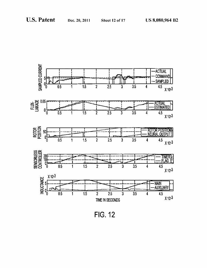
FIG. 12
INDUCTANCE
oocln
X —-I
C?ca
I__ -- -4-.. -
II+------r-- ---- -o--
I
~-4---------1..----__-| ,____-..4---------1-------
1 5 2 5
TIME IN SECONDS
-~r3-------r_ ---AUXLIARY
x103
SENSORLESS
CONTROLLER
—-v\:
oooc:
p (11
I I
---- -4-— __ ....+
---- -4.._ __T-___ _..J|:._ -- ---
1 1.5
I
2
I_ -- q- ———- -4..-_. --
rlf‘
I l I l I
___ _.. -— —--— 4- _-—— -q---__-+_-_—-
4
--*-- FLAG
" — TIMER
ROTOR
POSITION
c8
CD
‘
1.5
I I
2
-1—— —--- .r---- —.-'—— —— ———r ——-
.J-—-'"I
'L-—_-
3
-I-
3.5
— NEURAL OUTPUT
4
'5 x10³
,c
"""I'"""1"'“""I""""'"T""' j—; ---- ESTIMATED
5
x103
SAMPLEDCURRENT
DC
(’1
'9“
I
CWT"—0.5
up!“
—ACTUAL
-. --- COMMAND.
-- SAMPLED
4'5 x10³
U.S. Patent Dec. 20, 2011 Sheet 12 of 17 US 8,080,964 B2

U.S. Patent
1306\
START
INCREMENT
TIMER1
V
Dec. 20, 2011
SET FIRST
TIMER1 =
[1354
Sheet 13 of 17
1300
1308\PWM = DUTY
II 1310\
FILTER NEURAL
ANGLE
SET SHUTDOWN
FLAG
DECREMENT/mz
TIMER1
V
RESET NEURAL /1324
AME;
I
PWM =0 1325
US 8,080,964 B2
1328
YES
RESETPOSFLAG f133°
V
RESETTIMERI ‘332
V
RESET FIRST I333
SHUTDOWN
FLAG > 0
SET POSFLAG/1336
I,
SET TIMER1 = X/I338
I
RESET SHUTDOWN
FLAG
/1340
IL RESET NEURAL
ANGLE
/I342
I
FIG. 13
SET FILTER SLOPE
> 0
/I344 Vr
INCREMENT
TIMERZ
END
/1346
US 8,080,964 B2Sheet 14 of 17Dec. 20, 2011U.S. Patent
llE
if‘
cf)
I‘F'I'T
('0
I1:;
LL.
OI
‘—
5SI
><
33
Xr—‘n.
><
E2
'mm
_"
'—|—
I'
'"’3
no
II
Om
o_o
I_,_,u.II.LI
'T"N
.N
,1_,N
2mm
N
IO:
_.O..D_
.:
o.
I—mm
-.
II-=‘.
II
IOLLI
'I
II
II
Iczz
.I
II
II
I'l
II
“TVI—co
--I-7-
<0
I:-<o
T-r-
<0
II
I
II
II
II
IIII
I:\
rI
II
IIIII
II
II
III
II
II
II
II
II
II
II
‘
I:I
.-
1.J1
.L'
II...._m
_+_|._I,r>
-—.u)
-|-
to
II
.I.-I--I...
II
I..I--
II
I
|I
II
I:
I1'
:.‘
I|
II
II
III
‘I
‘II
\
II
II
II
II
I‘I
II
II
II:
:I
I.‘
II
\
II
I
‘1'“?
—'-f'—<f
1I-rfil
Qilfi‘i—Ii'J‘fi’:V
II
I
II
III
I.
3“"
I
II
III
II
‘I
I
II
II
IIIII
l‘
I.I
III
II
II
II
II
HI.
I
II/
II
III
II
I\I‘.
I
—I-u-—I
or)
—I—&—
or)
L4-“
(‘0
-I--‘&¢-I
or)
II
II
III
I\I
II
II
Il
II
II
II
II
IIII
I‘
II
III
II
III
III
II
II
II
II\
I
I[I
II
II
II
II
I“|
A-qL.—N
_l_
L—N
J—
J_.L_IN
-L..L
+..N
II
II
II
II
II
I.
I'l
II
II
II
II
I
-.
-:
I'
II
II
r-+-
--.
__
II
II
II
II
I1“
‘
II
II
II
II
Il‘
II
II
II
II
II
“"I""‘"
.1”.
r..._
,_,..,
1......
T.,..
-.\.._
II
III
II
II
II
III
II
II
I
II
III
II
II
‘l
II
II
II
I|
I
Is‘
II
III
II‘
II
I
‘o
II
lo
I}
I!o
II
I(3
fl’No
(”NV-o
oocoo
0
mama
°°°
‘°8
HEITIOHINOO
NIVW
BENIN”
NOIIISOd
.30103
ssamosnas
x
=3
_l
LL
TIME IN SECONDS
FIG. 14

U.S. Patent
1 START 1
V
1502\
CALCULATE
INDUCTANCE
‘1 15°4\ LOOKUP INDREF
Dec. 20, 2011
1506 @110
1508\YES
CALCULATE INDERR
Sheet 15 of 17
1 500
CLEAR
SET INDFLAG
W:
1415 INDERR=0 ”0
1516\ YES
CLEAR INDFLAG
SET COUNTDOWN
V
CLEAR LREF
1534\ 1
DECREMENT
TIMER
FIG. 15
US 8,080,964 B2
1536
®N°1538\ CLEAR
1540\
YES
TIMER
w
CLEAR
COUNTDOWN
1542\ V
SET 1NDFLAG
END

TIMERS
COMMUTATIONFLAG
INDUCTANCE
MAINCURRENT
0
-_Lo
—L
6
4
2
00'‘I
3
O
.
4
, J
1‘
5
TIME IN SECONDS
FIG. 16
6
7
37
L. r7
x103
i
1
o—---+--u+
0 ----;-----
0“ "ao"'
1
I
u--
dl
‘O
3"
I
3
II
'Lo':;ai
1"
l
I
3
....._+.‘...
"u
2
Il
-—---t 4——-—-I—----4~—-—-
l
l
2
' l
l.—
4
4
:1
'1|\—-.-qu.-———qI--—
5
l
i
5
—
'v
i
6
,5,sr--__
I
6
Il
l------l-----l-;_-.-¢
:----L
4 ’1'
I
-_---+---_4--_--
“--
"v
8
I
ESTIMATED
i
8
n
l
E
- - — SPEED ADJUST
\ 4i’
7
---- COUNTDOWN
9 x10³
9 x10³
U.S. Patent Dec. 20, 2011 Sheet 16 of 17 US 8,080,964 B2

US. Patent Dec. 20, 2011 Sheet 17 0f 17 US 8,080,964 B2
$00
INT 1714
START
SAVE SAMPLES /1716
1702\ INITIALIZE TO VARIABLES
PROCESSOR I
{ CALCULATE /1718
1706 CALCULATE
THERE FLUX-LINKAGE /1720
(OPTIONAL)
CALCULATE /1722
INDUCTANfE OR ANN
PROCESS SENSORLESS /1724
- ALGORITHM
CALCULAFTE SPEED /1723
I
h...—
vJUMPT TO 1730
THERE
FIG. 17

US 8,080,964 B2
1
NEURAL NETWORKAND METHOD FOR
ESTIMATING REGIONS OF MOTOR
OPERATION FROM INFORMATION
CHARACTERIZING THE MOTOR
CROSS-REFERENCE TO RELATED
APPLICATIONS
This application claims priority to US. Provisional Appli-
cation No. 60/622,968 and incorporates by reference this
provisional application in its entirety. Additionally, the appli-
cation incorporates by reference the disclosures provided in
Applicants’ co-pending PCT International Application Nos.
PCT/USO3/l6627, PCT/USOS/l 6628, PCT/USO3/l 6629,
PCT/USO3/l6630, and PCT/USO3/l6631.
FIELD OF THE INVENTION
The present invention relates to a method and system for
collecting characteristic information of a motor, a neural net-
work and method ofusing the same for estimating regions of
motor operation from information characterizing the motor,
and system and method for controlling motor operation using
the characteristic information, the neural network, or both.
BACKGROUND OF THE RELATED ART
Currently in the motor control industry, engineers require
various characteristic electrical andmechanical parameters to
design and control motors. The typical parameters necessary
to characterize the motor’s operation, for any aspect ofmotor
development, are winding current (i), rotor position (0),
torque and speed ((1)). The relationship among these param-
eters provides indicia of the performance of the motor and
system.
Related art methods to obtain motor operational param-
eters, either for design or system development, rely on finite
element analysis (FEA) and locked-rotor tests. FEA proves
useful in motor design and can be used to develop control
methods. However, FEA does not account for parameter dis-
tortion arising from influences external to the motor, such as
digital signal processing, sampling, or non-linear effects due
to noise or Pulse-Width Modulation (PWM) switching. All of
these influences are happenstance in typical motor drive sys-
tems.
Aside from FEA, the most prevalent method for obtaining
motor operational parameters employs the locked-rotor test.
According to this method, the motor rotor is locked at a
specific position and a voltage is induced across the motor
windings. Current and voltage measurements are made for
numerous rotor positions, and other parameters, such as
inductance and flux-linkage, are derived from the current and
voltage measurements. No converter or controller is required
to perform these measurements. Once all of the required
measurements are taken, the measured and derived data can
be used to control the motor. Although the locked-rotor test
provides highly accurate results, the measurements are time
consuming and may only be obtained through the operation
of an actual motor drive.
Currently, there is a trend in the motor drive industry to
eliminate rotor position sensors, which are used to provide
rotor position information for the control of a motor. Position
sensors increase the overall cost and decrease the overall
lifetime of the system. In low-cost, high-speed applications
like grinders, fans and vacuum cleaners, the presence of a
rotor position sensor adds cost to the motor drive system that
could be avoided by smart sensor-less based position estima-
15
25
30
35
40
45
2
tion techniques. Also, for high-temperature and physical dis-
turbance applications, the presence of a position sensor to
provide the rotor position is not preferred.
Additional background information on the modeling,
analysis, and control of switched reluctance motors (SRMs)
and sensor-less control techniques is provided in “Switched
Reluctance Motor Drives” by R. Krishnan.
Some sensor-less control methods use motor parameters
that are stored in the form of look-up tables within a micro-
controller. “Accurate Position Estimation in Switched Reluc-
tance Motor With Prompt Starting”, by Debiprasad Panda,
and V. Ramanarayanan (IEEE publication) provides a
description of state-of-the-art control techniques for sensor-
less control of SRMs.
As a substitute for position sensors and look-up tables,
artificial neural networks (ANNs) are increasingly being used
for inferring a rotor’s position using various sensor-less tech-
niques. So far, though, the large size ofANNs has made their
implementation in practical low-cost and high-speed systems
impossible.
All reference material cited herein is hereby incorporated
into this disclosure by reference.
SUMMARY OF THE INVENTION
An object of the present invention is to overcome the
above-described problems and limitations of the related art.
Another object of the invention is to provide a method for
collecting characteristic information of a motor.
Still another object of the invention is to provide a system
for collecting characteristic information of a motor.
A further object of the invention is to provide a neural
network for estimating regions ofmotor operation from infor-
mation characterizing the motor.
A further object ofthe invention is to provide a method for
estimating regions of motor operation, using a neural net-
work, from information characterizing the motor.
A further object ofthe invention is to provide a system for
controlling motor operation using the characteristic informa-
tion, the neural network, or both.
A further object ofthe invention is to provide a method for
controlling motor operation using the characteristic informa-
tion, the neural network, or both.
These and other objects ofthe inventionmay be achieved in
whole or in part by a method for collecting operational param-
eters of a motor. According to the method, the energization of
a phase winding of the motor is controlled to establish a
rotational operating point. Operational parameters of the
motor that characterize a relationship between the energiza-
tion control applied to the motor’s phase winding and the
motor’ s response to this control are monitored. And informa-
tion of the operational parameters, for the operating point,
that characterizes the relationship between the applied ener-
gization control and the motor’s response are collected.
The objects ofthe invention may also be achieved in whole
or in part by a system for collecting operational parameters of
a motor. The system includes a power converter that energizes
a phase winding of the motor to establish a controlled oper-
ating point. Sensors monitor operational parameters of the
motor characterizing a relationship between the energization
applied to the motor’s phase winding and the motor’s
response to the applied energization. A controller controls the
energization applied by the power converter and collects
information of the operational parameters for the operating
point from the sensors.
The objects of the invention may be further achieved in
whole or in part by a neural network that estimates the posi-
US 8,080,964 B2
3
tion of a motor’s rotor with respect to its stator. The network
includes a preprocessor that produces a substantially non-
linear response based on one or more variables. Each of a
plurality ofneurons produces a response based on a plurality
of variables. An input layer of the neural network includes a
group ofthe plurality ofneurons and each neuron ofthe input
layer produces a response based on the response produced by
the preprocessor. An output layer of the neural network
includes one of the plurality of neurons, which produces a
response based on the responses produced by the neurons of
the input layer.
The objects of the invention may be further achieved in
whole or in part by a method for estimating the position of a
motor’ s rotor with respect to its stator using a neural network.
The method includes generating a substantially non-linear
response based on one or more variables and generating, for
each input layer neuron ofthe network, a response based on a
plurality of variables, which include the substantially non-
linear response. Also, a network response is generated based
on the responses generated by the input layer neurons.
The objects of the invention may be further achieved in
whole or in part by a method for controlling a motor. Accord-
ing to the method, the motor’s region of operation is esti-
mated and a phase winding ofthe motor is energized when the
region of operation is estimated to be a region for applying
motoring torque. A determination is made whether a motor-
ing torque region of operation has been errantly estimated. If
the determination is affirmative, the energization ofthe motor
phase winding is discontinued.
The objects of the invention may be further achieved in
whole or in part by a system for controlling a motor. The
system includes an estimation component that estimates the
motor’s region of operation and an energization component
that energizes a phase winding of the motor when the region
ofoperation is estimated to be a region for applying motoring
torque. A determination component determines whether a
motoring torque region of operation has been errantly esti-
mated. If the determination is affirrnative, the energization
component discontinues energizing the motorphase winding.
BRIEF DESCRIPTION OF THE DRAWINGS
Preferred embodiments of the present invention will now
be further described in the following paragraphs ofthe speci-
fication and may be better understood when read in conjunc-
tion with the attached drawings, in which:
FIG. 1 illustrates a runtime data collection system for a
motor;
FIG. 2 illustrates an automatic test method for implement-
ing the collection of operational parameters using the system
illustrated in FIG. 1;
FIG. 3 illustrates a method for controlling and collecting
data from the system illustrated in FIG. 1;
FIG. 4 illustrates a related art neuron;
FIG. 5 illustrates a related art neural network that models a
motor’s magnetic characteristics using electrical signal
inputs;
FIG. 6 illustrates a neural network ofthe present invention;
FIG. 7 illustrates the relationship betweentorque andphase
winding inductance for a motor;
FIG. 8 illustrates a sensor-less control system ofthe present
invention;
FIG. 9 illustrates a two-phase SRM of the present inven-
tion;
FIG. 10 illustrates a circuit topology ofthe power converter
illustrated in FIG. 8;
10
15
20
25
30
35
40
45
50
55
60
65
4
FIG. 11 illustrates a sensor-less motor control algorithm
for rotor angle estimation;
FIG. 12 illustrates the results achieved by simulating the
application of the algorithm illustrated in FIG. 11 to the
sensor-less control system illustrated in FIG. 8;
FIG. 13 illustrates another sensor-less motor control algo-
rithm for rotor angle estimation;
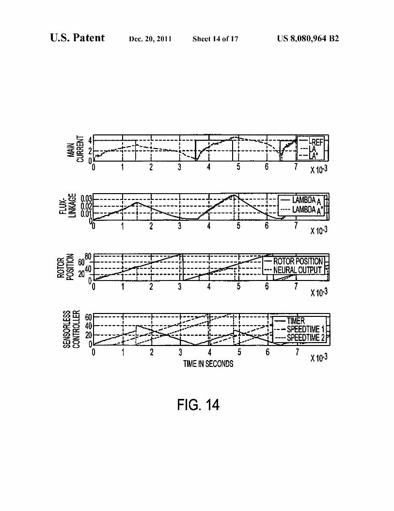
FIG. 14 illustrates the results achieved by simulating the
application of the algorithm illustrated in FIG. 13 to the
sensor-less control system illustrated in FIG. 8;
FIG. 15 illustrates a sensor-less commutation algorithm for
commutating current applied to a motor winding based on
estimates of the winding’s inductance;
FIG. 16 illustrates the results achieved by simulating the
application of the algorithm illustrated in FIG. 15 to the
sensor-less control system illustrated in FIG. 8; and
FIG. 17 illustrates a method of implementing the algo-
rithms illustrated in FIGS. 11, 13, and 15 via firmware in a
microprocessor or digital signal processor of the controller
illustrated in FIG. 8.
DETAILED DESCRIPTION OF THE INVENTION
FIG. 1 illustrates a runtime data collection system 100 for
a motor. In system 100, an alternating current (ac) voltage
source 102 provides power to a power converter 104. Power
converter 104 energizes one or more phase windings of a
motor 106 to induce rotational operation of the motor’ s rotor
under the control of a digital signal processor (DSP) control-
ler 108. DSP controller 108 monitors the voltage across, and
the current through, one ormore phase windings ofmotor 1 06
and the rotor angle of motor 106 based on information pro-
vided by a sensor 110. A computer 112 communicates with
DSP controller 108 to capture and process the monitored
voltage, current, and rotor position information.
During runtime operation of motor 106, data samples for
parameters such as speed, current (i), flux-linkage (A), and
rotor position can be collected and stored by computer 112.
The data collection can be repeated manually or automati-
cally to achieve data sets over the entire range of operating
points for motor 106.
FIG. 2 illustrates an automatic test method 200 for imple-
menting the collection of operational parameters using the
system illustrated in FIG. 1. Firmware on DSP controller 108
controls the data collection at the various operating points in
sequence while saving the data automatically at the end of
each capture. This method eliminates the laborious data col-
lection required by the related art locked-rotor tests. System
100 supports the measurement of the monitored parameters
simultaneously, without delays in measurement time.
According to method 200, DSP controller 108 initializes
202 control parameters for motor 106. Thereafter, DSP con-
troller 108 interacts with power converter 104 to start 204 the
rotation ofmotor 106’ s rotor. Then, DSP controller 108 waits
206 for a period of time before determining 208 whether the
rotor is rotating. Until DSP controller 108 determines 208 that
the rotor is rotating, DSP controller 108 continues attempting
to start 204 motor 106 and waiting 206 for a period of time
before reassessing its determination 208.
Once the rotor is determined 208 to be rotating, DSP con-
troller 108 sets 210 a test index value and establishes 212 test
settings for the indexed test. Using the established test set-
tings, motor 106’s rotor speed is controlled 214 via DSP
controller 108 and power converter 104 until the rotor speed
is determined 216 to have reached a steady state condition.
When the rotor speed reaches a steady-state condition,
DSP controller 108 sets 218 a test flag and collects 220 data

US 8,080,964 B2
5
regarding the voltage and current applied to motor 106 and
the rotor’s angular position with respect to the stator. There-
after, DSP controller 108 stops 222 the rotor’ s rotation, down-
loads 224 the collected data to computer 112, and increments
226 its test index. Ifthe incremented test index is determined
228 to be beyond the index value set for the last test measure-
ment, then the testing is discontinued. Otherwise, the motor is
restarted 204 and another measurement ofthe motor’ s opera-
tional parameters is made at the newly indexed operating
point, as indicated by operations 204-228. Note, however,
that the test index set in operation 210 is that identified by the
test index value incremented in operation 226.
FIG. 3 illustrates a method 300 for controlling and collect-
ing data from the system illustrated in FIG. 1. According to
method 300, DSP controller 108 initializes 302 control
parameters for motor 106. Thereafter, DSP controller 108
interacts with power converter 104 to start 306 the rotation of
motor 106 ’ s rotor and, then, determines 3 08 whether the rotor
is rotating. Until DSP controller 108 determines 308 that the
rotor is rotating, DSP controller 108 continues attempting to
start 306 the motor and reassessing its determination 308, via
a program executionjump to program label HERE 304 made
after every negative determination 308.
Once the rotor is determined 308 to be rotating, program
execution proceeds to program label THERE 310 and DSP
controller 108 waits 312 a period of time before determining
314 whether an interrupt condition has occurred. If the inter-
rupt has not occurred, DSP controller 108 jumps program
execution to program label THERE 310 and waits 312 a
period of time before reassessing its determination 314 as to
whether an interrupt has occurred. If the interrupt has
occurred, DSP controller 108 performs a programmingjump
316 to program label INT 318 to start an interrupt routine.
Once the interrupt jump 316 occurs, DSP controller 108
saves 320 data samples of the monitored motor parameters
and calculates 322 a current control value and also calculates
324 a flux linkage value for the motor, based on the data
samples of the monitored motor parameters. Then, DSP con-
troller 108 determines 326 the commutation angle ofthe rotor
by decoding the Ball-effect sensor signals. If DSP controller
108 determines 328 that pulse width modulation (PWM) is
used to control the energization of motor 106’s phase wind-
ings, then DSP controller 108 sets 330 the PWM duty cycle to
achieve the desired rotor speed for the motor. Otherwise,
program execution skips the PWM duty cycle setting opera-
tion 330 and proceeds directly to operation 332. After setting
330 the PWM duty cycle, DSP controller 108 determines 332
whether a speed calculation should be made. If so, DSP
controller 108 makes 334 this calculation. Otherwise, DSP
controller 108 determines 340 whether the motor rotor has
reached a steady-state speed. If a steady-state speed has been
achieved, DSP controller 108 sets 342 a Dataset flag. Other-
wise, DSP controller 108 executes a jump 344 in its process-
ing routine to execution label THERE 310, where DSP con-
troller 108 waits 312 for an interrupt condition to be identified
314.
After the Dataset flag is set 342 or DSP controller 108
calculates 334 the rotor’s speed, DSP controller 108 deter-
mines 336 whether the Dataset flag is set. If so, DSP control-
ler 108 executes a jump 338 to execution label DATA 346.
Otherwise, DSP controller 108 executes ajump 344 to execu-
tion label THERE 310.
Once the Dataset flag is set and program execution has
jumped 338 to execution label DATA 346, DSP controller 108
obtains 348 the current index value and determines 350
whether this index value is the last one in the set. If so, DSP
controller 108 shuts 352 down the system and ends the pro-
10
15
20
25
30
35
40
45
50
55
60
65
6
gram execution. Otherwise, DSP controller 108 saves 354 a
data structure containing the monitored and calculated opera-
tional parameters. Then, DSP controller 108 determines 356
whether the saved data structure is the last to be saved. Ifnot,
DSP controller 108 jumps 358 its processing to execution
label THERE 310 where it waits 312 for an interrupt condi-
tion 314. Otherwise, DSP controller 108 increments 360 the
index value, shuts down 362 the system operation, transfers
364 the saved data structures to computer 112, loads 366
index parameters, and jumps 368 its program execution to
label HERE 304 so that motor 106 may be restarted.
Method 300 was applied to system 100 for collecting the
operational parameters of a switched reluctance motor
(SRM) having two phases, though it could have been applied
to an SRM having any number of phases. In this application,
the measurements of three parameters were collected by the
system. These parameters were the current (i) provided to a
phase winding by power converter 104, the flux-linkage (A),
and the discrete position (0) ofmotor 106’s rotor.
The current (i) was collected via an amplified signal
obtained from a simple resistor transducer 114. The inexpen-
sive resistor transducer eliminated the need for an expensive
current (i) sensor in the system.
The flux-linkage (A) was estimated from the sampled cur-
rent (i) using Faraday’s law:
A:f(Va—Roi)dz
DSP controller 108 implemented the integration operation
through numerical techniques, based on power converter
104’s operational modes.
The winding voltage Va was determined from sampled
converter parameters. The rotor position (0) was measured
using two hall-effect sensors 110 whose signals provided
quadrature angle encoding designating 0, 45, and 90 degrees.
Due to the construction ofthe particular motorused in the test,
this angle encoding was well suited for decoding commuta-
tion cycles to drive the motor.
Phase inductance was calculated using both the measured
current and flux-linkage, in accordance with the expression
L:Mi. The monitored parameters were collected for each
phase over an entire rotation of the rotor, though collecting
these parameters from one phase was all that was required for
controlling the motor’s operation.
During each sample period the sampled parameters were
stored and used to calculate other motor parameters such as
flux-linkage (A). The speed of the rotor was measured to
determine the next point for data collection. If the data col-
lection flag was set for a specific time, DSP controller 108
saved the sampled and calculated parameters into an array.
Once all of the predetermined data points were collected,
system 100 was shut down. Then, system 100 sent the col-
lected data to computer 112, which stores and processes the
collected data as well as establishes the test conditions for
additional test points to be tested.
Table 1 provides a comparison ofthe collected parameters
with those obtained through FEA simulations.
TABLE 1
Rotor Position Measured Flux- FEA Flux-
(degrees) linkages (V—s) linkages (V—s) Error
27 0.0389 0.0378 2.9%
31 0.0448 0.0524 14.6%
38 0.0650 0.0713 8.7%
41 0.0722 0.0752 3.9%
45 0.0789 0.0757 4.2%

US 8,080,964 B2
7
As may be determined from Table l, the average flux
linkage error between the data measured by system 100 using
method 300 and the data obtained through the FEA simula-
tion was about 7%. The FEA data itself had an expected
simulation error of about 3%. Therefore, the data obtained
using system 100 and method 300 are closely correlated with
the FEA data.
Current (i), flux-linkage (A), rotor angle (0), and phase
inductance (L) are important parameters for applying sensor-
less control algorithms to a motor. Thus, the above-provided
discussion elicits the significance of obtaining actual runtime
measurements of these parameters. Obtaining runtime mea-
surements of the operational parameters eliminates the need
to employ expensive FEA design software for determining
the data used in control design, as well as the manual labor
involved in compiling the data at all the various operating
points using locked-rotor tests. The above-described collec-
tion methods provide motor parameters, as the controller
would experience them during runtime, for the purpose of
developing sensor-less control systems more rapidly. If any
noise or consistent, uncorrectable calculation error is present
in the control signals, then a method canbe devised to account
for such variances and bring the sensor-less control back to
the realm of high performance.
More specifically, a motor’s rotorposition canbe estimated
from the phase currents and flux-linkages of the windings,
based on the three-dimensional relationships among these
parameters. This fact may be used to model a sensor-less
estimation technique with an Artificial Neural Network
(ANN), since neural networks have an inherent capability for
system identification.
FIG. 4 illustrates a related art neuron 400.A neural network
consists of multiple neurons 400 in one or many layers with
suitable inputs to neurons 400 and a bias/threshold 408 con-
trol. Eachneuron 400 applies a set ofgains, known as synaptic
weights 402-406, to its input signals. Weights 402-406 are
multiplied by the corresponding inputs x1 -xn and the products
are summed with bias 408 in a summer 410 and then pro-
cessed through an activation function 412.
Generally, the more nonlinear a system is, the more neu-
rons that are required to model the system. In related art
neural networks, the layers ofneural nodes between the input
and output nodes (i.e., hidden layers) induce the non-linear
characteristics of the model. Consequently, the more non-
linear a system is, the more hidden layers that are required to
model the non-linearity ofthe system. Increasing the number
ofneurons and hidden layers increases the computation time
required to generate outputs for the neural network.
In high-speed and inexpensive applications, such as blend-
ers, the time required for a neural network to process a set of
inputs so as to obtain the position of the rotor is far too great
for practical applications. Inexpensive microcontrollers used
for motor control applications cannot satisfactorily process
the computations for a large ANN. And processors that are
capable of processing the computations of large ANNs in a
small amount of time are not feasible for low-cost applica-
tions. Therefore, the need for a better technique to infer rotor
position from neural networks for high speed motor applica-
tions is required.
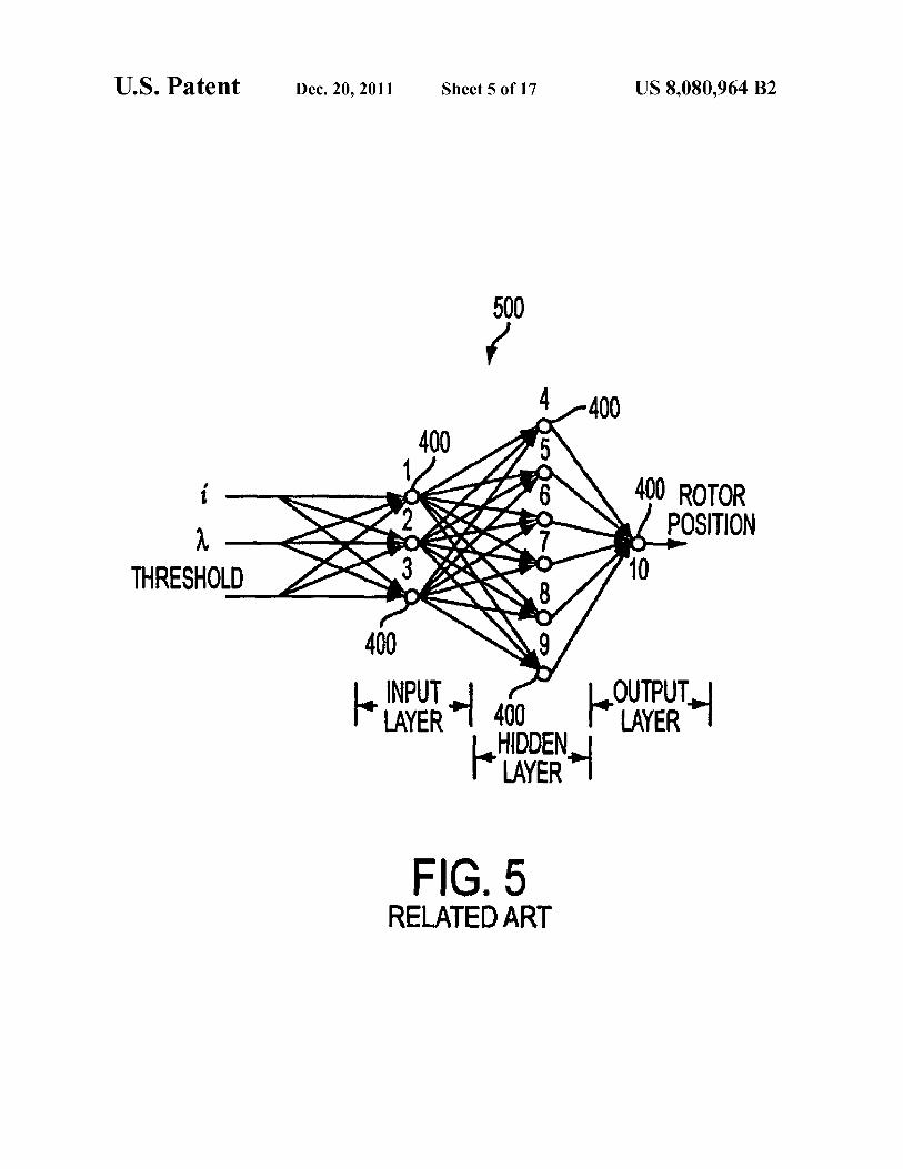
FIG. 5 illustrates a related art neural network 500 that
models a motor’s magnetic characteristics using electrical
signal inputs, such as the motor’s phase current (i) and flux-
linkage (A). Neural network 500 has ten neurons 400, of
which three constitute an input layer, six constitute a hidden
layer, and one constitutes an output layer. Only the six hidden
layer and one output layer neurons employ a bias signal in
neural network 500 and these bias signals are weighted in a
10
15
20
25
30
35
40
45
50
55
60
65
8
manner similar to the weighting applied to the other neural
inputs. Based on signals indicating a motor’ s phase current (i)
and flux-linkage (A), neural network 500 generates an esti-
mate of the motor’s rotor position.
FIG. 6 illustrates a neural network embodiment 600 ofthe
present invention. Similar to neural network 500, neural net-
work 600 generates an estimate of a motor’s rotor position
based on signals indicating the motor’s phase current (i) and
flux-linkage (2»). However, neural network 600 models the
motor’s magnetic characteristics with nearly the same
amount of accuracy as neural network 500 using only four
neurons 400. Neural network 600 has three input layer neu-
rons 400 and one output layer neuron 400. Both the input and
output layer neurons 400 employ biasing in neural network
600 and the biasing signals are weighted in a manner similar
to the weighting applied to the other input signals. Since
neural network 600 has no hidden layers for generating the
non-linearities needed to closely model the motor’ s magnetic
characteristics, a non-linearity is introduced to the input layer
neurons 400 by a multiplier 602. Multiplier 602 multiplies the
motor’s phase current (i) and phase-linkage (A) signals
together to produce a non-linear component representing the
motor’s magnetic characteristics and introduces this non-
linear product as an input to each neuron 400 of neural net-
work 600’s input layer.
While both neural networks 500 and 600 are similarly
capable of accurately estimating a motor’s rotor position
without the use of position sensors, neural network 600 does
so with much fewer neurons 400 and computations. This is
achieved by providing the additional pre-processed non-lin-
ear input to ANN 600. The non-linear input is a suitable
combination ofthe primary inputs, such as phase current and
flux-linkage, and provides the necessary dimension required
to model the non-linear behavior of the motor.
Table 2 compares the performance characteristics ofneural
networks 500 and 600 for estimating the rotor position of a
motor. In the comparative test conducted with the two net-
works, a back-propagation algorithm was used to train the
networks to produce estimates of a motor’s rotor position
based on the motor’s phase current (i) and flux-linkage (A).
Neural network 500 was trained to an average root-mean-
square (rrns) error of 5><10'5 in 40,000 epochs and neural
network 600 was trained to an rms error of 8.5><10'5 in rela-
tion to the results obtained through locked-rotor tests.
TABLE 2
Operational
Characteristic Neural network 500 Neural Network 600
Multiplications 40 17
Summations 30 12
Activations l 0 4
Total Operations 80 33
Computation Time 31.5 us 13 us
RMS Error 5 x 10*5 8.5 x 10*5
As indicated in Table 2, neural network 600 performs 33
mathematical operations to calculate the motor’s rotor angle
to an accuracy nearly the same as that achieved by neural
network 500 through 80 mathematical operations. Ofgreater
importance perhaps, neural network 600 estimated the rotor
angle with a similar degree of accuracy in less than half the
time required by neural network 500.
Generally speaking, anANNrequires training to model the
motor system relationships accurately. Training theANN can
be accomplished by various methods known in the related art.

US 8,080,964 B2
9
The motor data collection techniques discussed in connection
with FIGS. 1-3 can be used to extract the parameters that are
required to train theANN. For example, voltages and currents
from the motorwindings or the drive circuit can be sensed and
used to provide inputs to theANN to obtain the rotor position.
However, the techniques described above for modeling the
characteristics of a motor using an ANN are not limited to a
motor or to inferring rotor position, they can be applied to
infer any information for a system using pre-processed
inputs. Also, the data collection methods can be combined
with the neural estimators to achieve a quasi-self learning
sensor-less motor drive, as described below.
To generate motion for a motor rotor, torque must be
applied to the rotor. The motor torque relationship is
described by:
1dL_2——z
22%
According to this relationship, the sign ofthe torque depends
on the slope of the inductance with respect to the change in
angle. If the slope is positive, then the torque is positive, and
vice versa. Also, the magnitude of the torque is directly pro-
portional to the squared value of the current flowing in the
phase windings. From this relationship, several methods to
control the torque generation in the motor using sensor-less
methods can be developed. One such method relies on an
estimation of rotor position (0) to govern the torque genera-
tion, another method relies on an estimation of winding
inductance (L). In either case, the basic premise for generat-
ing torque is to control current conduction in the windings
with respect to the angular rotor region corresponding to
positive torque generation.
The angular symmetry of a motor ensures that the positive
torque region repeats every X90 degrees and the negative
torque region repeats every Y9X degrees, where X is Y/2
(e.g., X:45 and Y:90 for a two-phase switched reluctance
motor). Thus, to produce forward motoring, current must be
generated in the stator winding when the rotor angle is
between X90 degrees with respect to the approaching stator
pole. Minimal current should conduct through the stator
winding when the rotor angle is betweenY9X degrees, so as
to avoid producing negative torque during forward motoring
that will slow or even stall the rotor.
FIG. 7 illustrates the relationship betweentorque andphase
winding inductance for a motor. As illustrated in FIG. 7, when
current is applied to a phase winding as a rotor pole rotates
fromX90 degrees with respect to an approaching stator pole
associated with the phase winding, the inductance of the
phase winding increases monotonically and positive torque is
applied to the rotor. Conversely, when current is applied to the
phase winding as the rotor pole rotates from Y9X degrees
with respect to the stator pole associated with the phase wind-
ing, the inductance ofthe phase winding decreases monotoni-
cally and negative torque is applied to the rotor. The relation-
ship between phase inductance (L), phase current (i), and
torque may be used to control the operation of sensor-less
motor.
The basic goal of a sensor-less controller is to estimate
rotor position without using position sensors. The rotor posi-
tion may be estimated from estimates ofthe phase inductance
and flux-linkage, for both single-phase and multi-phase
SRMs, and is used to regulate the application ofcurrent to the
motor phases.
m
U
N
5
w
5
M
M
K
i
K
6
10
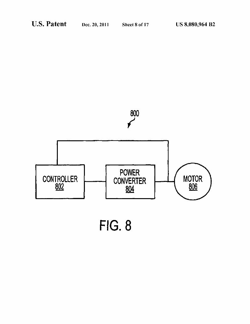
FIG. 8 illustrates a sensor-less control system 800 of the
present invention. System 800 includes a controller 802, a
power converter 804, and a motor 806, which may be a
two-phase switched reluctance motor (TPSRM) for the pur-
pose of this discussion. Controller 802 monitors voltage and
current signals that are indicative of the voltage and current
applied to a main phase winding ofTPSRM 806. From these
voltage and current signals, controller 802 estimates the flux-
linkage. Applying the monitored current and estimated flux-
linkage signals to neural network 600, which is implemented
by controller 802, controller 802 may estimate the rotor posi-
tion of motor 806. Based on the estimated rotor position,
controller 802 regulates the PWM signal applied to power
converter 804 so as to regulate the torque applied to the motor
rotor.
FIG. 9 illustrates a two-phase SRM 900 of the present
invention. TPSRM 900 includes four main phase windings
902 and four auxiliary phase windings 904. The stator poles
bearing auxiliary phase windings 904 are shifted 45 degrees
with respect to the stator poles bearing main phase windings
902. Although TPSRM 900 is a two-phase machine, main
phase windings 902 contribute nearly all of the torque pro-
duced in the machine. Auxiliary phase windings 904 are used
to start the rotation of the machine’s rotor and for recovering
energy from main phase windings 902 when main phase
windings 902 are not being energized.
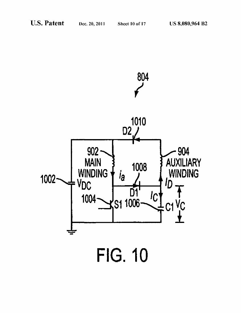
FIG. 10 illustrates a circuit topology of power converter
804 illustrated in FIG. 8. A direct current (dc) source 1002
provides a voltage Vdc across main phase windings 902 to
energize these windings when a switch 1004 is activated by a
PWM signal from controller 802. When the current in main
phase windings 902 is to be commutated, switch 1004 is
turned off and the energy stored in main phase windings 902
is partially transferred to the rotor as mechanical energy and
partially transferred to auxiliary phase windings 904 and
capacitor 1006 through diode 1008. When main phase wind-
ings 902 are re-energized, the energy stored in auxiliary phase
windings 904 is partially returned to capacitor 1006. Diode
1010 is optional in power converter 804.
An equation that controller 802 may use for estimating the
motor flux-linkage from the monitored current and voltage
signals is derived as follows. First, two sets of equations
modeling the behavior of TPSRM 806 and power converter
804 are derived, one for the conduction period and the other
for the non-conduction period of switch 1004. The devices in
power converter 804 are assumed to be ideal and, therefore,
the voltage drops across the devices and switching transients
of the devices and their induced effects are neglected. The
differential equations expressing the operation of the
machine, when switch 1004 is turned off, are provided below:
dM _
d1 = -Rala + (Vdc - Vc)
dM;_ R'
fi?——b%+W&—W)
ch (ia - ib)
d1: C
g+g+g=0
awm
J7 +me =Tc—Tl,

US 8,080,964 B2
11
where J is the inertia of the rotor (Kg-m2); B is the load
constant; La and Ab are the flux-linkages (V—s) ofthe main and
auxiliary windings, respectively; ia, i b, and ic are the currents
through main phase windings 902, auxiliary phase windings
904, and capacitor 1006, respectively; C is the capacitance of
capacitor 1006; and T8 and T] are the electromagnetic torque
(N-m) and load torque, respectively.
Equations describing the motorwhen switch 1 004 is turned
on are:
dk _
d1 = Vdc_Rala
4% .
W = Vc_Vdc_Rblb
dV i i
d: = C = Eb,where ib 20
g+g+g=0
Lia)
JE+me=TC—T,
The machine magnetic characteristics applied by control-
ler 802 in the determination ofthe motor flux-linkage may be
obtained from a finite element analysis (FEA) tool or by the
data collection techniques described previously. For the pur-
pose of deriving the flux-linkage equation below, the switch-
ing frequency of power converter 804 may be assumed to be
20 kHz, which determines the required sampling interval, and
the control algorithm may be assumed to be executed only
once per switching cycle. Since the flux linkages have a much
larger time constant than the sampling period, the average
flux-linkage may be derived as:
A :A +Aavg avggw, avg,tof
Amg,,m:f[dVd.—dR.I]dz
Ewe]?![(1 -d)dVc-(l -d) Vc(1-d)RaI]111,
where d is the duty cycle, Vdc is the source voltage, Ra and Rb
are the resistances ofthe main and auxiliary windings, respec-
tively, I is the sampled current, V6 is the voltage across the
capacitor, and dt is the sample period. Thus, the average
flux-linkage Mug sample period can be expressed, by sum-
ming the equations for A and AavgJofS as:avg,ton
Awff[Vac-(1 -d) Vc-RaUdl,
in light ofthe fact that output variables such as rotor position
and speed hardly change within a switching period.
FIG. 11 illustrates a sensor-less motor control algorithm
1100 for rotor angle estimation. This algorithm was experi-
mentally applied to system 800 using controller 802 to con-
trol the on and off switching of switch 1004 within power
converter 804 and thereby drive TPSRM 806. Controller 802
implemented neural network 600 so as to estimate TPSRM
806’s rotor position.
Based upon the rotor position estimated by neural network
600, controller 802 commutated the phase current applied to
main phase winding 902, by activating and deactivating the
PWM controlling the phase current, to regulate the torque
applied to the rotor. Power converter 804 was used to energize
the SRM phase windings using the single switch 1004 for
actively conducting current through main phase winding 902.
The energy stored in main phase winding 902 by its energi-
zation was passively degenerated through auxiliary phase
winding 904 during the PWM off state. Thus, the commuta-
tion of the current occurred as if the system was a single-
phase motor drive.
m
U
N
w
5
M
5
K
E
12
Although algorithm 1100 is designed to control a single
phase motor drive, multiple instances of this algorithm may
used in conjunction with multiple PWM drives to adapt the
commutation scheme for multi-phase systems.
Referring now to FIG. 11, algorithm 1100 uses the rotor
position obtained fromANN 600 to determine whether main
phase winding 902 should be conducting current or not. To
make this determination, a comparison is made as to whether
the rotor is in the conduction angle region with respect to the
stator pole. That is, controller 802 determines 1102 whether
the rotor poles are within 45 degrees of the stator poles they
are approaching. If not, energizing main phase winding 902
will not produce positive torque for the rotor. The algorithm
controls conduction by using a flag. This flag is set and reset
based on the determination of the rotor angle provided by
ANN 600. Ifthe rotor poles are determined 1102 to be within
45 degrees (i.e., the commutation angle) of the upcoming
stator poles, then a determination 1104 ofa Posflag’s value is
made. Ifthe rotor poles are determined 1 1 1 6 to be greater than
45 degrees with respect to the upcoming stator poles, then
Posflag is set 1118 to 1. Ifthe rotor poles are determined 1116
to be at an angle of 45 degrees with respect to the upcoming
stator poles, then the Posflag is left unchanged. After deter-
mining the angle ofthe rotor poles with respect to the upcom-
ing stator poles, controller 802 determines 1104, 1120 the
value of the Posflag. If the rotor-to-stator pole angle is less
than the commutation angle (i.e., less than 45 degrees) and the
Posflag value is 0, controller 802 will increment 1106 a timer
and update 1108 the PWM duty cycle. The timer is used to
determine the length of time main phase winding 902 will
conduct current.
A secondary operation is performed to determine whether
main phase winding 902 is conducting in the negative torque
region. Controller 802 digitally filters 1110 the rotor position
information generated byANN 600 andthen determines 1 1 12
whether the slope of the filtered signal is decreasing. If the
angle appears to be decreasing, then a Shutdown flag is set
1114.
If: (1) the rotor-stator pole alignment is determined 1102 to
be less than 45 degrees and the Posflag is not equal to 0; (2) the
rotor-stator pole alignment is determined 1116 to be 45
degrees; (3) the Posflag is set 1118 to l; (4) the slope ofthe
filtered rotor position signal is determined to be positive; or
(5) the Shutdown Flag is set 1114 to 1, then a determination
1120 is made whether the Posflag has a value greater than 0.
If so, then the timer is decremented 1122, the neural angle is
reset 1124, the PWM signal is set 1126 to a value of 0, and a
determination 1128 is made whether the timer value equals 0.
Otherwise, the determination 1128 of the timer value is
directly made without performing the intervening operations
1122-1126.
Ifthe timer is determined 1128 to have a value of0, then the
Posflag is reset 1130 to a value of0, the timer is reset 1132 to
a value of 0, and a determination 1134 is made whether the
Shutdown Flag has a value greater than 0. If the timer is
determined 1128 to have a value different from 0, then the
determination 1 134 is made whether the Shutdown Flag has a
value greater than 0 without performing the intervening
operations 1130 and 1132.
If the Shutdown Flag is determined 1134 not to have a
value greater than 0, then the algorithm is ended. Otherwise,
the Posflag is set 1136 to a value of l, the timer is set 1138 to
a value ofX, the Shutdown Flag is reset 1140, the neural angle
is reset 1142, the slope of the filtered angle signal is set 1144
positive, and the algorithm is ended.
More generally, the sensor-less control algorithm illus-
trated in FIG. 11 uses the rotor position obtained from ANN

US 8,080,964 B2
13
600 for estimating the motor’s rotor position so as to deter-
mine whether the motor’s phase winding should be conduct-
ing current or not. First a comparison is made as to whether
the rotor is in the conduction angle region with respect to the
stator pole. Positive torque can only be generated in the motor
when its rotor is in the conduction angle region.
Algorithm 1100 controls conduction by using a flag. This
flag is set and reset based on the determination of the rotor’s
angle. IfANN 600 estimates that the rotor position (e) is less
than the commutation angle, then the flag is reset. If the
commutation angle has been reached, then the algorithm will
set the flag. While the angle is less than the commutation
angle and the flag is not set, algorithm 1100 will increment a
timer and update the PWM duty cycle. The timer is used to
determine the length of time the phase has been conducting.
A secondary operation is performed to determine whether
the phase is conducting in the negative torque region. First,
controller 802 digitally filters the output ofANN 600 and then
determines whether the slope ofthe filtered output is decreas-
ing. Ifthe angle appears to be decreasing then a shutdown flag
is set.
Once the commutation angle is achieved, the position flag
is set. The timer and duty cycle are no longer updated. Con-
troller 802 will set the PWM duty cycle to zero and start
decrementing the timer. The basis ofthe control is to equalize
the time that the phase conducts with the time that it does not
conduct. Thus, to produce positive torque, the phase is ener-
gized and a timer is incremented until the commutation angle
is achieved. Thereafter, the negative torque region will be
bypassed by withholding energization of the main phase
winding for the same amount of time. The algorithm, as
explained, works well if the motor has reached a constant
speed, i.e., the amount of time for positive torque region
conduction equals that needed to bypass the negative torque
region.
To achieve highly satisfactory operation when the motor
speed is changing, a secondary operation is performed to
determine whether the rotor angle is in the positive or negative
torque region. Depending on the training of ANN 600, the
estimation of the angle in the negative torque region should
vary greatly from the estimation while in the positive torque
region. An appropriate HR filter may accomplish the signal
processing required for the decision making task of shut-
down.
Shutdown is used to correct for commutation error if the
machine speed is not constant. The shutdown mechanism
may be controlled via a shutdown flag. If the flag is set,
algorithm 1100 will enter a special state wherein the PWM is
turned off, sets the position flag for countdown, and adjusts
the countdown timer to a special value. The special count-
down value is much less than a normal conduction period
timer value.
FIG. 12 illustrates the results achieved by simulating the
application of algorithm 1100, illustrated in FIG. 11, to the
sensor-less control system 800 illustrated in FIG. 8. Referring
to FIG. 12, current conduction through the motor’s main
winding 902 starts just prior to entering the positive torque
region and algorithm 1100 senses this condition and shuts the
PWM off. The start ofthe positive torque region is denoted by
rotor position 0 (zero). The current conduction produces a
short, but significant, current pulse in the negative torque
region having a duration that is directly proportional to the
shutdown timer value used in the secondary operation,
described above.
Whether setting the countdown normally due to the com-
mutation angle being reached or whether in the special shut-
down mode, the algorithm operation is the same. A value is
10
15
20
25
30
35
40
45
50
55
60
65
14
placed in the countdown timer and the PWM is shut off.
Algorithm 1100 then proceeds to decrement the timer. Once
algorithm 1100 has completed its countdown, all the flags and
controlling variables are reset, algorithm 1100 will begin to
count up, and the whole process repeats.
FIG. 13 illustrates another sensor-less motor control algo-
rithm 1300 for rotor angle estimation. Algorithm 1300 and
1100 similarly adjust a timer to bypass a motor’s negative
torque region. However, the basic premise of algorithm 1300
is to estimate the speed of the machine and adjust the timer
just prior to countdown and PWM turn off. If the machine is
speeding up, the timer will reflect this and algorithm 1300
should adjust the bypass countdown such that the time
required to bypass is less. Ifthe machine is slowing down, just
the opposite should happen, algorithm 1300 should adjust the
timer up to increase the amount oftime required to bypass the
negative torque generation region.
The time adjustment for the bypass region is accomplished
by adding a second timer that counts the duration between
resets of the position flag. The timer value at PWM shut off
due to the commutation angle being reached is exactly twice
what the bypass duration should be, thus the countdown can
be set, at the commutation time, to have a value equal to half
the value ofthe second timer. More simply stated, the bypass
duration is set equal to halfthe amount oftime controller 802
estimates for the combined durations of the conduction and
non-conduction phases of operation.
Algorithm 1300 operates as follows. Controller 802 deter-
mines 1302 whether the angle estimated by ANN 600 is less
than 45 degrees. ANN 600 produces an angle estimate of
between 0-90 degrees. Rotor angle estimates of between 90
and 45 degrees indicate the region where the rotor pole has
passed or is leaving the stator pole it was aligned with previ-
ously. A 45-degree estimate corresponds to the point where
the rotor is equally far from its adjacent stator poles. The
region indicated by an estimate of 45-0 degrees is where the
rotor pole is closer to the stator pole it is approaching for a
specified direction of rotation.
Accordingly, if ANN 600 estimates an angle that is less
than 45 degrees, the motor is operating in the conduction
region, that is, switch 1004 is to be turned on. If the rotor
position obtained from ANN 600 is greater than 45 degrees,
switch 1004 has to be turned off, if it is on, or has to remain
off.
Controller 802 determines 1304 whether the position flag,
Posflag, has a value of 0. This flag determines whether the
motor is in the conduction (positive torque) region or not. If
the position flag, Posflag, has a value of 0, a timer, Timer1, is
incremented 1306. Ifthe position flag is not 0, algorithm 1300
proceeds to operation 1320, discussed later. Timer1 counts
the conduction time during a conduction interval.
After Timer1 is incremented 1306, controller 802 calcu-
lates and sets 1308 the PWM duty cycle. Then, controller 802
obtains and filters 1310 an angle estimate provided by ANN
600. Based on the filtered angle estimate, controller 802
determines 1312 whether the angle estimated byANN 600 is
increasing or decreasing with respect to the previous angle
that was obtained and filtered. Ifthe filtered slope ofthe angle
estimates is negative, the rotor is moving in the specified
direction of rotation and approaching the next stator pole in
the direction ofrotation. Ifthis slope is positive, the rotor pole
is moving away from the statorpole it is supposed to approach
in the direction of rotation. In other words, a positive slope
means that ANN 600 is estimating increasing angles (oppo-
site to the intended direction of rotation), instead of decreas-
ing angles.

US 8,080,964 B2
15
Ifcontroller 802 determines 1312 that the slope is less than
0 (decreasing angles), controller 802 sets 1314 the shutdown
flag. Ifcontroller 802 determines 1312 that the slope is greater
than 0, controller 802 proceeds to operation 1320.
At operation 1320, controller 802 determines 1320
whether Posflag has a value greater than 0. If so, which means
its value is l, Timer1 is decremented 1322 (counting down
Timer1, non-conduction period), the estimated angle pro-
vided byANN 600 is reset or zeroed 1324, the PWM is turned
off 1326, and program execution proceeds to operation 1328.
In operation 1326, PWM:0 indicates that the PWM is turned
off, which results in switch 1004 being turned off. Timer1 is
incremented during conduction and decremented during non-
conduction of switch 1004. If Posflag is determined 1320 not
to have a value greater than 0, then program execution pro-
ceeds to operation 1328 without performing the intervening
operations 1322-1326.
In operation 1328, controller 802 determines 1328 whether
the value of Timer1 is 0. If Timer1’s value is zero, controller
802 resets 1330 the value ofPosflag, which makes its value 0,
and resets Timer1 1332 and a flag called First 1333. Timer1
would be equal to zero if Timer1 had been decremented to 0
(finished the conduction interval) or if operation 1354 set
Timer1 to be 0, when algorithm 1300 is called for the first
time. The First flag indicates the first time sensor-less algo-
rithm 1300 is called by controller 802, that is, when the motor
is turned on. Accordingly, resetting 1333 the value of First
will only occur the first time algorithm 1300 is called.
Before proceeding further (to operation 1334), consider
the circumstance where controller 802 determines 1302 that
the estimated rotor angle is not less than 45 degrees. Control-
ler 802 determines 1316 whether the angle estimated byANN
600 is greater than 45 degrees. If not, controller 802 deter-
mines that the motor has just been turned on or there is no
voltage across, or current in, the windings and no angular
position has been estimated by ANN 600. However, if the
rotor angle is estimated 1316 to be greater that 45 degrees,
controller 802 sets 1318 the value ofPosflag to 1, so the PWM
remains offin the next cycle. Then, controller 802 determines
1350 whether the value of the First flag is less than 1. If so,
which means its value is 0, controller 802 sets 1352 the value
of FIRST to 1. Then, controller 802 sets 1354 the value of
Timer1 to be equal to half the value of Timer2, which calcu-
lates the total time for conduction (positive torque region) and
non-conduction (switch 1004 is off to bypass the negative-
torque region). Therefore, controller 802 sets 1354 Timer1 to
be half of Timer2 under the premise that the conduction
interval is equal to the non-conduction interval. Thereafter,
controller 802 proceeds to operation 1320, which is described
above. If the estimated rotor angle was not determined 1316
to be greater than 45 degrees or the value of First flag was not
determined 1350 to be less than 1, then the value ofTimer1 is
set 1354 to half the value of Timer2 without performing the
intervening operations 1318 and 1350-1352 or 1352, respec-
tively.
Returning now to operation 1334, if controller 802 deter-
mines 1328 that the value ofTIMER1 is not 0 or if controller
has reset 1333 the value ofFirst flag 1334, then controller 802
determines 1334 whether the Shutdown flag was set in opera-
tion 1314. If so, then controller 802 determined that the esti-
mated angles provided byANN 600 were decreasing. There-
fore, ifthe angles are decreasing, then position flag Posflag is
set 1336 to a value of l and Timer1 is set 1338 to a time
determined by controller 802. Also, controller 802 resets
1340 the Shutdown Flag to a value of 0, the estimated angle
provided byANN 600 is cleared 1342, and controller 802 sets
1344 the filter slope to a positive value in 1334. Then, con-
10
15
20
25
30
40
45
50
55
60
65
16
troller 802 increments 1346 the value ofTimer2. If controller
802 determines 1334 that the Shutdown flag is not greater
than 0, then Timer2 is incremented 1346 without performing
the intervening operations 1336-1344.
Algorithm 1300 is set to run every 50 microseconds by
controller 802. Before algorithm 1300 is called for the first
time, all the timers and flags are cleared or set to 0. As the
motor runs, algorithm 1300 will determine the conduction
intervals based on the position estimated by ANN 600 every
50 microseconds.
FIG. 14 illustrates the results achieved by simulating the
application of algorithm 1300, illustrated in FIG. 13, to the
sensor-less control system 800 illustrated in FIG. 8. Referring
to FIG. 14, the simulation shows that the initial non-conduc-
tion period is too long. The countdown period was artificially
adjusted to demonstrate the position error correcting capabil-
ity of the algorithm. The PWM should initiate conduction
almost 0.0005 seconds earlier in the second conduction
period. To correct this error, the speed estimation is used to
adjust the countdown timer. This timer’s value is adjusted in
consecutive conduction periods until the sensor-less conduc-
tion period matches the positive torque region. The flux-
linkage estimation drives the neural network output for com-
mutation angle derivation, as previously discussed. The speed
estimation is used to correct error in the speed timers, which
are used to determine the non-conduction duration.
As an alternative to commutating the current applied to the
main winding 902 of motor 806 based on estimating the
rotor-stator pole alignment with ANN 600, the commutation
may be based on an estimate of the winding’s inductance.
This approach is similar to that described for commutating
the current based on the estimation of rotor position, in that
both approaches use a flag to determine the region of conduc-
tion in conjunction with a timer so as to determine the lengths
of time to conduct or not. However, with the latter approach,
the method for setting or resetting this flag and thus commu-
tating the current is based on an inductance estimate and not
an estimate of rotor position provided by an ANN.
There are two methods by which inductance can be esti-
mated: a two-point current sampling method and a flux-link-
age divided by current method. Both methods are described
below.
The two-point current sampling method relies upon the
assumption that the switching period is sufficiently fast that
the inductance is relatively constant during the on-period of
the switch. Based on this assumption, the slope ofthe current
during this time is directly proportional to the inductance of
the phase and the inductance ofthe phase winding is related to
the motor’ s rotor angle. Thus, ifthe inductance is calculated,
the angle of the rotor can be predicted.
Two points are sampled from the phase current measure-
ments. The two sample points should be obtained during the
same conduction period of the switch to get a proper mea-
surement. The method is viable across many speeds and cur-
rent levels if the system can tolerate steady-state error in the
current control.
Low-performance drives for appliances are the intended
application. Also, this method is subject to signal noise. If
noise is present in the sampled signals, it is difficult to deter-
mine the actual inductance signal. Thus, methods to accu-
rately measure the winding current may be appropriate.
The flux-linkage method involves estimating the flux and
then calculating the inductance via the relationship:

US 8,080,964 B2
17
where A is the estimated flux linkage, i is the estimated current
flowing through the main winding, and L is the inductance.
From the relationship:
1dL_2——z
=2d0’
where 0 is the angle of rotor alignment with respect to the
stator and T is the torque applied to the rotor, it may be
determined that if the change in inductance is positive then
the torque generation will also be positive. This principle is
relied upon to accomplish a commutation scheme.
Accordingly, algorithms 1100 and 1300 could be modified
to perform current commutation based on the above-de-
scribed methods for estimating the inductance ofthe motor’ s
winding, rather than estimating the motor’s rotor position. As
such, the estimated inductance would determine whether to
set or reset the commutation flag in algorithms 1100 and
1300.
FIG. 15 illustrates a sensor-less commutation algorithm
1500 for commutating current applied to a motor winding
based on estimates ofthe winding’s inductance. The premise
of control in algorithm 1500 is similar to that for algorithms
1100 and 1300. A flag controls the conduction region. A
lookup table derived from FEA data is implemented and used
to generate an inductance reference level. The first step is to
select a reference level from the lookup table by which the
estimated inductance is evaluated. The method of selection is
based on a current reference level that can be either derived
from the torque command or from the actual sensed current
signal. When the estimated value exceeds the reference, the
PWM signal should be terminated. Again a timer is used to
determine the duration between the time that the PWM is shut
off and when it should be reinitiated.
Since there is no inherent error correction in this method, if
the inductance estimation is incorrect, the algorithm will
produce incorrect commutation angles. This is due to the
absolute scale values that are used for determining the time at
which the PWM should be shut off. Other methods have to be
used to correct for any inconsistencies in the estimation pro-
cess.
Algorithm 1500 is implemented by controller 802 as fol-
lows. The inductance of the motor’s main winding 902 is
estimated 1502 based on estimates of the flux linkage and
current flowing through main winding 902. Based on the
current estimate or an estimate of the torque applied to the
rotor, an inductance reference value is selected 1504 from a
lookup table. If an Indflag is determined 1506 to be greater
than 0, then an Inderr value is calculated 1508 and a determi-
nation 1510 is made whether the calculated Inderr value
exceeds 0. Otherwise, the determination 1510 is made
whether the Inderr value exceeds 0 without performing the
intervening operation of calculating 1508 the Inderr value.
If the Inderr value is determined 1510 to be greater than 0,
then an Indflag is set 1512 and a determination 1514 is made
whether the value ofInderr is 0. Otherwise, the determination
1514 is made whether the value of Inderr is 0 without per-
forming the intervening operation of setting 1512 Indflag.
If the value of Inderr is determined 1514 to be 0, then the
value of Indflag is cleared 1516 and a determination 1518 is
made whether the value of Indflag is greater than 0. Other-
10
15
20
25
30
35
40
45
50
55
60
65
18
wise, the determination 1518 of whether Indflag is greater
than 0 is made without performing the intervening operation
of clearing 1516 the value of Indflag.
Ifthe value ofIndflag is determined 1518 to be greater than
0, then the value of I_ref is set 1520, a timer value is incre-
mented 1522, a countdown value is cleared 1524, and a deter-
mination 1526 is made whether the value of Indflag is 0.
Otherwise, the determination 1526 is made whether the value
ofIndflag is 0 without performing the intervening operations
1520-1524.
Ifthe value of Indflag is determined to be 0, then the value
of Countdown is set 1528 and a determination 1530 is made
whether the value ofCountdown is greater than 1 . Otherwise,
the determination 1530 is made whether the value of Count-
down is greater than 1 without performing the intervening
operation of setting 1528 the Countdown.
Ifthe value ofCountdown is determined 1530 to be greater
than 1, then the value ofI_ref is cleared 1532, the Timer value
is decremented 1534, and a determination 1536 is made
whether the Timer value is 0. Otherwise, the determination
1536 is made whether the Timer value is 0 without perform-
ing the intervening operations 1532 and 1534.
If the Timer value is determined 1536 to be 0, then the
Timer value is cleared 1538, the Countdown value is cleared
1540, the Indflag value is set 1542, and the algorithm is
discontinued. Otherwise, the algorithm is discontinued with-
out performing the intervening operations 1538-1542.
A method of adjusting the negative torque region using a
timer that estimates the speed can be used for induction error
correction in conjunction with algorithm 1500. The induction
estimation error should be consistent enough that the com-
mutation angles happen at the same angle, but not necessarily
at the correct angle. Thus, a timer, used to measure the dura-
tion between commutation angles, can be used to adjust the
position error. The value in the countdown timer of algorithm
1500 can be adjusted up or down to correct any error that
occurs during the positive torque region conduction time.
A significant difference between algorithm 1500 and algo-
rithm 1300 is that algorithm 1500 uses an indication of the
phase winding’s inductance to determine positive torque and
negative torque regions of the motor, instead of the rotor
position (or angle). Referring back to FIG. 7, it may be seen
that the positive inductance slope region corresponds to the
positive torque region and the negative inductance slope
region corresponds to the negative torque region (or non-
conduction interval). Where the inductance remains constant,
no torque is generated even if main winding 902 is commu-
tating. Therefore, if algorithm 1500 determines that the
inductance is increasing 1510, it will commutate current
through main winding 902 by turning on switch 1004. If a
negative inductance slope is detected or a zero inductance
slope is detected, controller 802 will stop commutating cur-
rent through main winding 902.
Inductance flag, IndFlag, will be set (IndFlag:1) if a posi-
tive inductance slope is detected 1510. Operation 1518 deter-
mines whether IndFlag is 1 or 0. If the flag’s value is greater
than 0, then the rotor is in the conduction region and controller
802 will commute current through switch 1004.
I_ref is the current reference (or commanded current)
determined by controller 802. Operation 1522 will increment
the Timer and proceed. The Timer will count the conduction
interval or the positive inductance slope interval.
If the inductance error from operation 1510 is less than 0,
operation 1514 checks ifthe inductance error is equal to zero
or not. If operation 1514 determines the error is not zero,
program execution proceeds to operation 1518. If the induc-
tance error is determined 1514 to be 0, then the inductance

US 8,080,964 B2
19
estimated is less equal to the inductance reference 1504. This
means the inductance is constant at two different time inter-
vals and, hence, the motor is operating in a zero torque region.
This means that the rotor is completely aligned or unaligned
with reference to the stator and the inductance flag is cleared
or set to 0. This would result in algorithm 1500 proceeding to
operation 1526 which sets the Countdown Flag (Count-
down:l), which results in the controller 802 withholding
conduction until the timer reaches 0. The Countdown flag will
remain at a value of 1 until the Timer has decremented 1534
to 0, which occurs in operation 1536. Hence, operation 1532
clears I_ref, which will result in non-conduction and switch
1004 being turned off. The Timer decrementing to 0 indicates
the negative torque region or zero torque region and the
negative torque interval lasting as long as the positive torque
interval.
If the inductance error 1508 has a value less than 0, the
IndFlag will remain at a value of 0 as it was set when algo-
rithm 1500 ran for the first time or by operation 1540. If the
inductance flag has a value of 0, then the current reference
I_ref will remain at a value of 0 and switch 1004 will remain
off. If the Timer is decremented to 0, it is cleared/reset, the
Countdown Flag is cleared/reset, and the inductance flag is
set to l for the next cycle, which will result in algorithm 1500
checking for the positive inductance slope region again. Ifthe
Timer does not have a value of 0, algorithm 1500 ends and
waits till the next time it is called.
FIG. 16 illustrates the results achieved by simulating the
application of algorithm 1500, illustrated in FIG. 15, to the
sensor-less control system 800 illustrated in FIG. 8. In the
simulation, the rotor’s start angle was intentionally set so as
not to coincide with the beginning of the conduction angle
region. The start angle was set 20 degrees into the region, thus
introducing significant error in the system. As may be deter-
mined from inspection of FIG. 16, the inductance reference
algorithm gives a very good indication of the commutation
angle. Coupling the good inductance reference with an
adjustment to the countdown timer, based on the measured
time between commutation angles, an excellent correction of
the induction error may be achieved.
Another sensor-less commutation control method employs
an inductance slope method. This method calculates the
inductance slope from a filtered, estimated value. When the
slope of the filtered variable is near zero or negative, then a
flag will be set to shutdown the PWM. All rules still apply
with the use oftimers to determine length ofconduction/non-
conduction periods. This method inherently has some error
correction for commutation without any speed adjustment.
Since an absolute scale is not used, the algorithm can correct
position errors in the presence of estimation errors by using
the general shape of the inductance.
FIG. 17 illustrates a method of implementing the algo-
rithms illustrated in FIGS. 11, 13, and 15 via firmware in a
microprocessor or digital signal processor of controller 802.
The processor firmware implements the algorithm calcula-
tions on a repetitive interrupt basis. Controlled automatically
by the processor, an interrupt service routine can be written to
sequentially control the current and speed loops while per-
forming any necessary calculations, estimations, or deci-
sions. The software routine calculates current commands
based on current samples and adjusts a PWM duty cycle. The
sensor-less algorithm determines whether that PWM is
allowed to run or whether is should be turned off.
Referring now to FIG. 17, controller 802’s processor ini-
tializes 1702 the program variables for the start of motor
operation and motor 806 is started 1704. Execution proceeds
to program label THERE 1706 where program execution
10
15
20
25
30
35
40
45
50
55
60
65
20
waits 1708 for a timed interrupt to occur. When the timed
interrupt is determined 1710 to occur, program execution
jumps 1712 to program label TNT 1714.
Uponjumping 1712 to label INT 1714, program execution
saves 1716 samples of the monitored parameters used to
control the motor’s operation. From these samples, a current
control parameter is calculated 1718, the flux-linkage may be
calculated 1720, the motor’s estimated phase inductance or
rotor-stator alignment is calculated 1722, and one of the sen-
sor-less algorithms 1100, 1300, or 1500 is executed. There-
after, a determination 1726 is made whether to calculate the
rotor’s speed. If determination 1726 is affirmative, then the
rotor’s speed is calculated 1728 andprogram executionjumps
1730 to program label THERE 1706. Otherwise, program
executionjumps 1730 to program label THERE 1706 without
calculating the rotor’s rotational speed.
The foregoing description illustrates and describes the
present invention. However, the disclosure shows and
describes only the preferred embodiments of the invention,
but it is to be understood that the invention is capable ofuse in
various other combinations, modifications, and environ-
ments. Also, the invention is capable of change or modifica-
tion, within the scope of the inventive concept, as expressed
herein, that is commensurate with the above teachings and the
skill or knowledge of one skilled in the relevant art.
The embodiments described herein are further intended to
explain best modes known ofpracticing, the invention and to
enable others skilled in the art to utilize the invention in these
and other embodiments, with the various modifications that
may be required by the particular applications or uses of the
invention. Accordingly, the description is not intended to
limit the invention to the form disclosed herein.
What is claimed is:
1. A neural network for estimating the position ofa motor’ s
rotor with respect to its stator, the network comprising:
a preprocessor that produces a substantially non-linear
response based on a plurality of variables; and
a plurality of neurons, wherein:
an input layer of the neural network comprises a group of
the plurality of neurons and each neuron of the input
layer produces a response based on the plurality ofvari-
ables and the response produced by the preprocessor,
an output layer ofthe neural network comprises one ofthe
plurality of neurons, which produces a response based
on the responses produced by the neurons of the input
layer, and
information indicative of: (l ) the amount ofcurrent applied
to a phase winding of the motor and (2) the motor’s
flux-linkage are variables provided to the preprocessor
for use in producing the substantially non-linear
response and also provided to each of the input layer
neurons for use in producing its respective response.
2. The neural network of claim 1, wherein the input layer
comprises all but one of the neurons.
3. The neural network of claim 2, wherein the input layer
consists of three neurons.
4. The neural network ofclaim 1, wherein the preprocessor
produces the non-linear response by multiplying two of the
variables together.
5. The neural network ofclaim 1, wherein the preprocessor
produces the non-linear response by dividing one of the vari-
ables by another.
6. The neural network of claim 1, wherein the position is
estimated for the rotor of a switched reluctance motor.
7. A neural network for estimating a value, the network
comprising:

US 8,080,964 B2
21
a preprocessor that produces a substantially non-linear
response based on a plurality of variables; and
a plurality of neurons, wherein:
an input layer of the neural network comprises a group of
the plurality of neurons and each neuron of the input
layer produces a response based on the plurality of vari-
ables and the response produced by the preprocessor,
an output layer ofthe neural network comprises one of the
plurality of neurons, which produces a response based
on the responses produced by the neurons of the input
layer, and
each ofthe variables provided to the preprocessor for use in
producing the substantially non-linear response is also
provided to each of the input layer neurons for use in
producing its respective response.
8. The neural network of claim 7, wherein the input layer
comprises all but one of the neurons.
9. The neural network of claim 8, wherein the input layer
consists of three neurons.
10. The neural network of claim 7, wherein the preproces-
sor produces the non-linear response by multiplying two of
the variables together.
11. The neural network of claim 7, wherein the preproces-
sor produces the non-linear response by dividing one of the
variables by another.
12. A method for estimating the position of a motor’ s rotor
with respect to its stator using a neural network, the method
comprising:
generating a substantially non-linear response based on a
plurality of variables;
generating, for each input layer neuron of the network, a
response based on the plurality of variables and the
substantially non-linear response; and
generating a network response based on the responses gen-
erated by the input layer neurons, wherein
information indicative of: (l ) the amount ofcurrent applied
to a phase winding of the motor and (2) the motor’s
flux-linkage are variables provided to the preprocessor
for use in producing the substantially non-linear
20
30
22
response and also provided to each of the input layer
neurons for use in producing its respective response.
13. The method of claim 12, wherein the substantially
non-linear response is generated by multiplying two of the
variables together.
14. The method of claim 12, wherein the substantially
non-linear response is generated by dividing one of the vari-
ables by another.
15. The method of claim 12, wherein the neural network
input layer consists of three neurons, a single output layer
neuron produces the network response, and no neuron exists
in an intermediate layer between the input layer and the
output layer.
16. The method of claim 12, wherein the position is esti-
mated for the rotor of a switched reluctance motor.
17.A method for estimating a value using a neural network,
the method comprising:
generating a substantially non-linear response based on a
plurality of variables;
generating, for each input layer neuron of the network, a
response based on the plurality of variables and the
substantially non-linear response; and
generating a network response based on the responses gen-
erated by the input layer neurons, wherein
each of the plurality of variables provided to the prepro-
cessor for use in producing the substantially non-linear
response is also provided to each of the input layer
neurons for use in producing its respective response.
18. The method of claim 17, wherein the substantially
non-linear response is generated by multiplying two of the
variables together.
19. The method of claim 17, wherein the substantially
non-linear response is generated by dividing one of the vari-
ables by another.
20. The method of claim 17, wherein the neural network
input layer consists of three neurons, a single output layer
neuron produces the network response, and no neuron exists
in an intermediate layer between the input layer and the
output layer.