f e b r ua r y n o .298 1955 - studebaker-info.org
TRANSCRIPT

F E B R U A R Y
N o.. 2 9 8 1 9 5 5
TRANSMISSION REMOTE CONTROLALL 1955 MODELS
P l e a s e r e c o r d t h i s a r t i c l e o n t h e S e r v i c e
B u l l e t i n R e f e r e n c e p a g e a t t h e e n d o f t h eTransmission section of your 1955 Passenger CarShop Manual.
The conventional or overdrive transmissionremote con t ro l sh i f t l eve r space r p la te (Pa r tNo. 532554) has been revised by being madet h i c k e r , from .0478" t o .058" - .062". Al lparts depot stock of P a r t N o . 5 3 2 5 5 4 s p a c e rPlate will be of the revised version.
Likewise, a longer spacer, Part No. 537545,for the Automatic Drive remote control gear-shift lever spring housing is available throughParts depots and the original spacer, Part No.
532556, wi l l no longer be ca r r i ed . The newspacer (Part No. 537545) for Automatic Drivec a r s i s n o w .776" - .780" l o n g i n s t e a d o f.763" - . 773" as in the original spacer.
The purpose of these changes is to reduceend play and consequent looseness of the remotemechanism. This will make it easier to secureproper adjustments.
CHANGES IN CONVERTERVALVE BODY ASSEMBLY
P l e a s e r e c o r d t h i s a r t i c l e on t h e S e r v i c e B u l l e t i n R e f e r e n c e p a g e a t t h e e n d o f t h e
Studebaker Automat ic Drive sec t ion o f your 1955P a s s e n g e r Car Shop Manual
Effective w i th Transmiss ion Ser ia l Nos .SCH-2101 (DG150M-16G6), SP-10801 (DG250M-16G8and 6H),, and ST-1281 (DG250TM-E7 and E12), theconverter shuttle valve is regulated by multi-p l e d i s c c l u t c h p r e s s u r e i n s t e a d o f d i r e c td r ive c lu tch p ressure when in d r ive range .
This gives converter pressures of 50 to 70psi when in low gear and 20 to 30 psi in drive-in te rmedia te o r d i rec t d r ive . Because of the
greater differential between Converter andd i rec t d r ive c lu tch p ressures a t the t ime o f
t h e s h i r t i n t o d i r e c t , t h e S h i f t i n t o d i r e c tdrive from drive-intermediate is more posit ive.
P A G E
A U T O M A T I C D R I V E C H A N G E S . . . . . . . . . 3
A U TO M AT I C DRIVE SHIFT S P E E D S - 16G8. . .. 3BATTERY SPECIFIC G R A V I T Y C HA N G E D . . . . 1B O DY SYMBOLS - U LT R A- V I S T A . . . . . . .. 4
C A R B U R E T O R G A S K E T - 6 H . E 3 8 . . . . . . . .. 3CARBURETOR J E T .050" E7,E12,E13,E28,E38 1 0
C O N V E R T E R - 1 7 A . ............... 6
C O N V E R T E R P A R T NUMBERS ........... 2
C O N V E R T E R V A LV E BODY CH A N G E S ....... 1D E F R O S T E R H E A T C H E C K S . ......... 10D I R E C T I O N A L SI GN A L WI R I N G - E S E R I E S . . 6F E N D E R- T O- C O W L SQUEAK C O R R E C T I O N .... 10G A S O L I N E M I L E A G E C H A RT ........... 4
H O R N TONE. ................... 2
IGNITION LOCK RA T TL E ......... 3
MULTIPLE D I S C CL U T C H S E R V I C E P A R T S .... 6
O V E R D R I V E C H E C K - O U T C H A R T S R E V I S E D . . . 8-9O V E R D R I V E R E V E R S E L O C K O U T S W I T C H ..... 7
R E A R QU A R T E R MOULDING P AN E L. ....... 4
R E A R Q U A R T E R U P P ER MOULDING ....... 2
S P E E D O M E T E R D R I V E G E A R A N D PINION-6H(AD) 2
T R A N S M I S S I O N R E M OT E C O NT R O L. ...... 1
BATTERY IMPROVEMENTSLOWER SPECIFIC GRAVITY
P l e a s e r e c o r d t h i s a r t i c l e o n t h e S e r v i c eB u l l e t i n R e f e r e n c e p a g e s a t t h e e n d o f t h eElectrical sections of your 1955 Passenger CarShop Mnual and your 3R Series Trucks ShopManua l .
Improvements in the separators now used inWillard Storage Datteries placed in Studebakerc a r s a n d t r u c k s h a v e m a d e p o s s i b l e b e t t e rovercharge and undercharge life and also longers t o r a g e life of the ba t te ry when used wi the lec t ro ly te o f 1 .260 spec i f ic g rav i ty a t fu l lcharge. This is to be compared with a previousfull cha rge specificaiton of 1.280-1.300 sp .g r .
The new, "low gravi ty” battery has been usedin production on the Pacif ic Coast for some
G O O D S E R V I C E C R E A T E S C U S T O M E R G 0 0 D w I L L

No. 298 S E R V I C E B U L L E T I N F E B R U A R Y 1 9 5 5
time and entered South Rend production recently.Phe new battery is easily identified by astamping on the negat ive ce 11 connector s t rap ,which reads: “Ful l CH 1 260 "1. .
The Willard model designation of this bat-tery remains the same, HDW-l-100.
CONVERTER PART NUMBERS
P l e a s e r e c o r d t h i s a r t i c l e o n t h e S e r v i c eB u l l e t i n R e f e r e n c e page a t t h e e n d o f t h eStudebaker Automat ic Drive sec t ion o f your 1955Passenger Car Shop Manual.
The following chart shows the part numbersto use when o rder ing to rque conver te r s fo rs e r v i c e r e p l a c e m e n t :
ConverterModel Years Model Designation Part No.
Champion 1950-54 9G,10G,12G,14G,15G 5278251955 17G6 537316
Commander 1950 17A 5290741951-54 H,3H,4H,5H 530331
1955 16G8 536501
President 1955 6H 536501
Truck 1955 E7,E12 536501
REAR DOOR AND REAR QUARTERWINDOW UPPER MOULDING CLIP
HELD BY SCREW
P l e a s e r e c o r d t h i s a r t i c l e o n t h e S e r v i c eB u l l e t i n R e f e r e n c e p a g e a t t h e e n d o f t h e B o d ysection of your 1955 Passenger Car Shop Manual.
The rear door and rear quarter window mould-ing c l ips were o r ig ina l ly he ld in p lace by asnap fastener that went into a hole in the body.A revision has been made to the extent thatthis clip is now held by a metal screw.
The metal screw requires a smaller hole thant h e o r i g i n a l f a s t e n e r . When you install thenew type clip on a car originally equipped withthe snap- in fas tener , sea l the o r ig ina l ho lewith tape and with a #31 drill bit drill a newhole alongside the original hole directly underthe centerline of the moulding. Use a Part No.638-#8-6G metal screw to mount the clip.
The new par t numbers , toge the r wi th thecanceled original part numbers, of this mouldingclip are:
New CancelPart Part
No. No. Part Name
311276 308506 Rear door-rear quarter windowupper moulding clip, right
311275 304781 Rear door-rear quarter windowupper moulding clip, left
SPEEDOMETER DRIVE GEAR ANDPINION -- PRESIDENT WITH
AUTOMATIC DRIVEP l e a s e r e c o r d t h i s a r t i c l e on t h e S e r v i c e
Bul le t in Reference page at the end of theStudebaker Automat ic Drive sec t ion o f your 1955Passenger Car Shop Manual.
Effective with Automatic Transmission SerialNo. DG-250-M 7001, a f ive - too th speedomete rd r ive gea r , Pa r t No . 537565 , i s u sed in 6HPresident models equipped with Studebaker Auto-matic Drive and 3.54 rear axle. Th i s d r ivegear requires the use of Part No. 537620 pinionhaving 19 teeth.
Prior to Automatic Transmission serial No. DG-250-M 7001, a six-toothed speedometer drivegear, Part No. 531040, was used in conjunctionwith a 23-toothed speedometer pinion, Part No.527689.
When replacing the speedometer drive gear orpinion on 1955 President models equipped withStudebaker Automatic Drive, check the trans-m i s s i o n s e r i a l n u m b e r b e f o r e o r d e r i n g t h er e p l a c e m e n t p a r t .
OFF-TONE HORN
P l e a s e r e c o r d t h i s a r t i c l e on t h e S e r v i c e
B u l l e t i n R e f e r e n c e p a g e a t t h e e n d o f t h e Electrical section of your 1955 Passenger CarShop hanua 1.
Unsatisfactory tone from one horn may betraceable to a horn bracket that is too stiff ,a result of having too many laminations and animproper spacer. This will affect the tone ofone horn more than the other because of thedifference in frequencies.
The correct horn bracket has two laminationson each s ide , a t o t a l o f f o u r . I f a hornbracket has morethe bracket with
than four laminations, replacea new one.
STARTINGSUPPLEMENT
SERIALS LISTED INNO.1 TO SHOP MANUAL
P l e a s e m a k e the following change on t h eForeword page of your copy of Supplement No. 1to 1955 Studebaker Passenger Car Shop M a n u a l .
The serial numbers for Hamilton were trans-posed for Los Angeles. To correct , cross outthe words “Los Angeles, Ca l i fo rn ia” and im-media te ly above ink in , “Hami l ton , Ontar io ,Canada. "
Cross ou t the p r in ted words , “Hami l ton ,Ontario, Canada” and immediately below ink in,“Los Angeles, California.”
2
S E R V I C E B U L L E T I N
STUDEBAKER AUTOMATIC DRIVEP l e a s e record t h i s a r t i c l e o n page 2 8 o f
Supplement NO . 1 to 1955 Studebaker P a s s e n g e rCar Shop Manual.
In addition to the changes for StudebakerAutomatic Drive given on page 28 of your copyof 1955 Shop Manual Supplement No. 1, there isalso a change in multiple disc clutch make-up,Commander and President speedometer drive gear,and in Commander shift speeds.
MULTIPLE DISC CLUTCH
CHAMPION The multiple disc clutch consistsof 3 thin, s in te red f r i c t ion d i scs and 4 f l a tsepara to r p la tes ( iden t i f i ed by a notch at theend of one lug), and a spacer located betweenthe innermost separator plate and the retractorsp r ing inne r p la t e . (Previously, there was acertain amount of “dish” shape to the separatorplates .) F h e s e multiple d i s c f r i c t i o n d i s c splus separator p l a t e s m u s t b e s e r v i c e d i n c o m -p l e t e s e t s .
This means that for whatever reason any oneplate or disc is replaced in a Champion trans-m i s s i o n , a l l s e v e n c o m p o n e n t s ( 3 d i s c s , 4plates) must be installed new and the originaldiscs and plates discarded.
COMMANDER and PRESIDENT The Commander andP r e s i d e n t t r a n s m i s s i o n h a s 4 t h i n , s i n t e r e df r i c t ion d i scs and 5 separa to r p la tes and as pacer, loca ted as in the Champion , in i t smultiple disc clutch.
The same service instruction given above forChampion models applies to the Commander andP r e s i d e n t m u l t i p l e d i s c c l u t c h . S e r v i c e i ns e t s o n l y a n d r e p l a c e a c o m p l e t e s e t o f 4f r i c t i o n d i s c s p l u s 5 s e p a r a t o r s w h e n e v e r r e -p lac ing any one or more of either discs orP l a t e s i n t h e m u l t i p l e d i s c c l u t c h a s s e m b l y .
COMMANDER& PRESIDENT SPEEDOMETER DRIVE GEAR
The transmission used on the Commander andPresident models has a five-toothed speedometerdrive gear.
CARBURETOR-TO-AIR CLEANER GASKET1955 PRESIDENT MODELS
AND E38 TRUCK
P l e a s e r e c o r d t h i s a r t i c l e o n t h e S e r v i c eB u l l e t i n R e f e r e n c e page a t t h e e n d o f t h eGasoline System sections of your 1955 PassengerCar S h o p Manua 1 a n d 3 R S e r i e s Trucks ShopManua 1.
Excessive gasoline consumption or too rich amixture at high speeds may result grom obstruc-t i o n o f t h e v e n t s b y t h e c a r b u r e t o r - t o - a i rcleaner gasket. If this gasket is not properlypositioned, it can cover the vent tubes.
F E B R U A R Y 1955 No. 298
1955 COMMANDER MODEL SHIFT SPEEDS -DG250MTRANSMISSION - 6.70 x 15 TIRES
AND 3.31 REAR AXLE
SPEEDOMETERTYPE OF SHIFT MPH
Light th ro t t le upshi f t 1 -2 8-102-3 22-24
Ful l th ro t t l e upsh i f t 1 -2 25-282 -3 44-47
Kickdown upshift l - 2 37-402 -3 68-72
Closed th ro t t l e downsh i f t 3 -2 18-202 -1 9-11
Kickdown downshift l imit 3 -2 62 -662 -1 14-16
Par t th ro t t l e Kickdown l imit 3-2 35-38
The inner opening of this gasket is squarewi th b ias -cu t co rne r s . Two opposite sides ofthe square have one inden ta t ion each a t thecen te r . The other two opposite sides each havea pair of holes for the purpose of clearing theven t s a t the top o f the ca rbure to r . I f t h egasket is installed 90° (one quarter turn) fromthe cor rec t pos i t ion , a l l four ven ts wi l l beobstructed.
T h e r e f o r e , c h e c k t h e c a r b u r e t o r - t o - a i rcleaner gasket position when investigating con-ditions of excessive gasoline consumption orrich mixture at high speeds.
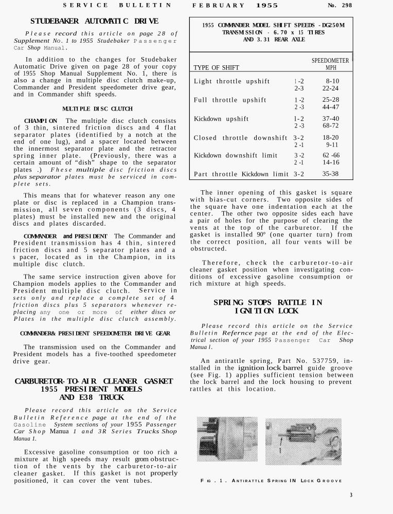
SPRING STOPS RATTLE INIGNITION LOCK
P l e a s e r e c o r d t h i s a r t i c l e o n t h e S e r v i c eB u l l e t i n Refernce page a t t h e e n d o f t h e E l e c -trical section of your 1955 Passenger Car ShopManua l .
An antirat t le spring, Part No. 537759, in-stalled in the ignition lock barrel guide groove(see Fig. 1) applies sufficient tension betweenthe lock barrel and the lock housing to preventra t t l e s a t th i s loca t ion .
F IG . 1 . A N T I R A T T L E S P R I N G I N LO C K G R O O V E
3

No. 298 S E R V I C E B U L L E T I N F E B R U A R Y 1 9 5 5
BODY DESIGNATIONS FOR STYLESADDED TO 1955
PASSENGER CAR LINE
P l e a s e r e c o r d t h i s a r t i c l e o n page 2 8 o fSupplement No.1 to 1955 Studebaker P a s s e n g e rCar Shop Manual.
In addition to the body designation symbolslisted on page 21 of Service Bulletin No. 293,the following symbols are added to cover sedanand station wagon models equipped with Ultra-Vista wrap-around windshield:
D 4 - 16G6 Champion and 16G8 Commander DeluxeStat ion Wagon
D6 0 16G6 Champion and 16G8 Commander RegalStat ion Wagon
D8 - 16G6 Champion and 16G8 Commander DeluxeAmbulet
D1 0 - 16G6 Champion and 16G8 Commander RegalAmbulet
F2 - 16G6 Champion and 16G8 Commander Custom2-door sedan
F4 - 16G6 Champion and 16G8 Commander Deluxe2 -door sedan
w2 - 16G6 Champion and 16G8 Commander Custom4 -door sedan
w4 - 16G6 Champion and 16G8 Commander Deluxe4-door sedan
W6 - 16G6 Champion and 16G8 Commander Regal4-door sedan
Y4 - 6H President Deluxe 4-door sedanY6 - 6H President state 4-door sedan
NOTE.. --It may be easier to remember these newbody symbols by keeping in mind that all Ultra-Vista equipped cars have symbols ending in evenn u m b e r s ( 2 . . .4.. .6.. .) and that none of thecoupe or hardtop m o d e l s i s equipped w i t h t h eUltra-Vista windshie ld.
REAR QUARTER PANEL-AND-FENDERMOULDING UPPER PANEL
P l e a s e r e c o r d t h i s a r t i c l e o n t h e S e r v i c eB u l l e t i n R e f e r e n c e page at the end of the Bodysection of your 1955 Passenger C a r Shop Manual .
311069 Rear Quarter Panel-and-Fender Moulding,Upper Left
311082 Rear Fender Side Moulding, Right311063 Rear Fender Side Moulding, Left
Original production mouldings for the upperp a n e l o f t h e t h r e e - p i e c e c o v e r o f t h e r e a rfender joint were held in place by two stud nutsand three snap fasteners.
GASOLINE MILEAGE CHART
A revised moulding upper panel , Part No.311066-7, is now being used. This moulding hastwo studs, one at the top and the other a fewinches below it , and two screws through a taba t t h e b o t t o m . W h e n i n s t a l l e d , t h e s e t w obottom screws are covered by the fender sidemoulding.
P l e a s e r e c o r d t h i s a r t i c l e o n t h e S e r v i c eB u l l e t i n R e f e r e n c e page a t t h e e n d o f t h eGasoline System section of your 1955 PassengerCar Shop Manual.
The gasoline consumption figures in the ac-companying chart are the result of tests madewith cars in good mechanical condition and runat constant speeds over a measured course.
4 (Cont'd. on P. 6)
F I G. 2
1. R E A R Q T R. U P P E R M O U L O I N G 5 . U P P E R P A N E L
2 . R E A R Q T R. C O R N E R M O U L O I N G 6 . CE N T E R P A N E L
3 . R E A R Q T R. LOWER MOULDI NG 7 . LO W E R P A N E L
4 . P A I N T M O U L O I N G M O U L O I N G
When cur ren t s tocks o f the o r ig ina l - typemoulding are depleted, only the new type willb e f u r n i s h e d . W h e n r e p l a c i n g a n o r i g i n a lm o u l d i n g w i t h t h e n e w t y p e , s e a l t h e o l dfas ten ing ho les wi th pu t ty o r t ape and dr i l lnew holes for the studs and mounting screws.Use the new moulding panel as a template. I tis also necessary to cut a slot in the front ofthe fender s ide mould ing to c lea r the upperpanel moulding tab that f i ts beneath the sidemoulding.
A new fender side moulding is also beingused , the only d i f fe rence f rom the or ig ina lbeing that the new side q oulding has this slot.The new side noulding can be used with theoriginal-type upper moulding panel.
The new parts are:
Part NO . Part Name
311068 Rear Quarter Panel-and-Fender Moulding,Upper Right

S E R V I C E B U L L E T I N F E B R U A R Y 1 9 5 5 No. 298
GASOLINE MILEAGE CHART
MODEL - TRANSMISSION - AXLE
16G6 CHAMPIONConvent ional(4 .10 to 1 Axle )
Overdr ive(4 .56 to 1 Axle )
(Conv .)(Conv .)(Conv. )(OD)( O D )
Automat ic Drive(3 .54 to 1 Axle )
16G8 COMMANDER -- 224.3 -- V8Convent ional(4 .1 to 1 Axle )
Overdrive(4 .27 to 1 Axle )
(Conv .) 20 19 2 2 . 8 32,2 8,1(Conv. ) 40 18 21 .6 64,4 7,7(Conv. ) 60 15 1 8 . 0 96,6 6,4(OD) 40 23 2 7 . 6 64,4 9,8(OD) 60 19 2 2 . 8 96,6 8,1
Automatic Drive(3 .54 to 1 Axle)
20 22 2 6 . 440 20 2 4 . 060 17 2 0 . 4
32 ,264,496,6
- -
9,48,57,2
16G8 COMMANDER -- 259.2 -- V8Convent iona 1(3 .54 to 1 Axle )
Overdrive(3 .73 to 1 Axle )
(Conv. )(Conv. )(Conv. )(OD)(OD)
MILES KILOMCONSTANT PER PER
SPEED U.S. IMPERIALMPH GALLON GALLON
PER PERHOUR LITER
20 2240 2260 17
20 214 0 1960 1540 2660 20
2 6 . 4 32,2 9,42 6 . 4 64,4 9,42 0 . 4 96,6 7,2
2 5 . 2 32,2 8,92 2 . 8 64 ,4 8,11 8 . 0 96,6 6,431 ,2 64,4 11 ,12 4 . 0 96,6 8,5
20 23 2 7 . 6 32,2 9,840 22 26.4 64,4 9,460 18 21 ,6 96,6 7,7
20 19 2 2 . 8 32 ,2 8 ,140 19 2 2 . 8 64,4 8,1G O 16 1 9 . 2 96,6 6,8
40 1960 1640 2460 20
Automatic Drive
20 19
(3 .31 to 1 Axle ) 40 2060 17
6H PRESIDENTConvent iona l 20 19
(3 .92 to 1 Axle ) 40 1860 15
Overdrive (Conv. ) 20 1 8
(4 .27 to 1 Axle ) (Conv. ) 40 17(Conv. ) 60 14(OD) 40 21(OD) 60 18
Automatic Drive 20 19
(3 .54 to 1 Axle ) 40 1860 16
2 4 . 0 32,22 4 . 0 64,42 0 . 4 96,6
2 4 . 0 32,22 2 . 8 64,419.2 96,62 8 . 6 64,42 4 . 0 96,6
8,58,57,2
8,58,16,8
10,28,5
2 2 . 8 32,2 8,12 4 . 0 64,4 8,52 0 . 4 96,6 7,2
2 2 . 8 32,221 ,6 64,41 8 . 0 96,6
21 .6 32,22 0 . 4 64,41 6 . 8 96,62 5 . 2 64.42 1 . 6 96,6
2 2 . 8 32,22 1 . 6 64,41 9 . 2 96,6
8,17,76,4
7,77,26,08,97 . 7
8,17 . 76,8
TERS
5

No. 2 9 8 S E R V I C E B U L L E T I N F E B R U A R Y 1 9 5 5
These figures should be used as a guide when TRUCKS WIRED FORmaking mileage tests. DIRECTIONAL SIGNALS
Because of the extremely wide variation of P l e a s e r e c o r d t h i s a r t i c l e o n t h e S e r v i c efac tors affecting gaso l ine mi leage - - such as B u l l e t i n R e f e r e n c e page at the e n d o f t h ed r i v e r h a b i t s , re la t ive humidi ty , a l t i t ude , E l e c t r i c a l s e c t i o n o f y o u r 3 R S e r i e s T r u c k sambient temperature, road surface, wind force Shop Manua 1.and direction, condition of engine, carburetion,i g n i t i o n , amount and uni formi ty of tire pres-sures,, and many more - - i t i s p o s s i b l e t o
Effec t ive wi th the fo l lowing t ruck se r ia l
establish accurate gasoline consumption figuresnumbers, w i r e s a r e i n c l u d e d i n t h e w i r i n g
only by using accredited mileage tester equip-h a r n e s s f o r t h e c o n n e c t i o n o f d i r e c t i o n a l
ment and strictly following the test proceduress i g n a l s : E5-115443, E6-14562, E7-1030,
or the manufacturers.E10-38049, E l l - 1 1 6 0 5 , E12-147, E13-105,E14-1902, a n d E15-14315. S ta r t ing Canad ian
Always, in a gasoline test , try to have the plant production Serial No. He5-101.
owner a long to see the results. Explain to himbriefly how the tester works so he wi l l haver a i t h i n i t , then make test runs at constantspeeds , on l eve l roads , i n b o t h d i r e c t i o n s .
AUTOMATIC DRIVE MULTIPLEDISCCLUTCHSERVICE PARTS
P l e a s e r e c o r d t h i s a r t i c l e o n t h e S e r v i c eB u l l e t i n R e f e r e n c e page a t t h e e n d o f t h eStudebaker Automa tic Drive Sec tion of your 1955Passenger Car Shop Manual.
When i t i s necessa ry to rep lace e i the r amultiple disc c lutch friction disc or a f r i c t iondisc p la te in any au tomat ic t ransmiss ion , a l lthe friction discs and all the plates should bereplaced in complete sets . Parts necessary to
1950 COMMANDER AUTOMATICDRIVE TORQUE CONVERTER
P l e a s e r e c o r d t h i s a r t i c l e o n t h e S e r v i c eB u l l e t i n R e f e r e n c e Page a t t h e e n d o f t h eStudebaker Automatic Drive Shop Manua 1.
Orig ina l ly , the torque converter (Part No.529074) for 1950 Commander (17A) model Auto-matic Drive had eight mounting studs. This hasnow been revised to contain but six studs, thetwo studs eliminated were diametrically opposed.
The converter with six studs is interchange-make the replacement are: able with the eight-stud converter.
No.Part NO. Part Name Req’d. Mode 1
537702 Friction Disc 3 All Champion 1950-554 All Commanders and Presidents 1950-554 E7 and El2 Trucks
537699 Frict ion Disc Plates 4 All Champion 1950-555 All Commanders and Presidents 1950-555 E7 and El2 Trucks
*537720 Spacer 1 Champion 1950-55 DG-150 Transmission Serial N O.
NOTE SCH-1001 and up with RED serial plateCommander 1950-55 DG-200 Transmission Serial No.
A l l t r a n s m i s s i o n s a f t e r t h e trans- SCO-1001 and up with BLACK serial platemiss ion serials g i v e n a t t h e r i g h t Commander 1950-55 DG-200-M Transmission Serial No.a r e p r o d u c e d w i t h t h e P a r t N o . SCC-1001 and up with BLUE STRIPES ON ALUMINUM537720 space r a s a componen t o f se r i a l p l a t etheir Multiple Disc Clutch assembly. President 1955 DG-250-M Transmission Serial No.It is not necessary to replace a spacer SP-1001 through SP-7000 with WHITE serial plateas a part of installing new discs and E7 and El2 Truck DG-250-TM Transmission Serial No.p la t e s . ST-1001 through ST-1183 with YELLOW serial plate
l The spacer, Part NO. 537720, is required because the discs (Part No. 537762) are thinner thanthose previously used and the plates (Part No. 537699) are flat,, rather than dished as were theo r i g i n a l t y p e p l a t e s . Ins ta l l the spacer be tween the innermos t f r i c t ion d i sc p la te and theretractor spring inner plate.
NOTE. --When overhauling a multiple discdrums without the NDC centrifugal bleedbleed va lve .
c l u t c h , e i g h t e e n (18)) r e t r a c t o r springs are used o n l o wvalve and 12 retractor springs in transmissions with the

S E R V I C E B U L L E T I N F E B R U A R Y 1 9 5 5 No. 298
OVERDRIVE TRANSMISSION PRODUCED TRANSMISSION ASSEMBLIES WITH OVERDRIVEWITHOUT REVERSE LOCKOUT SWITCH
Par tP l e a s e r e c o r d t h i s a r t i c l e o n t h e S e r v i c e No. Model Application
B u l l e t i n R e f e r e n c e pages a t t h e e n d o f t h eT r a n s m i s s i o n s e c t i o n s o f y o u r 1955 P a s s e n g e r 537681 10G-16G6Car Shop Manual and your 3R Series Trucks Shop 537692 16G8-H-6HManua 1. 684825 3R5,3R10,E5,E10
Reverse lockout switches are no longer usedin the p roduc t ion o f overdr ive t ransmiss ionassemblies. This results in a revision or theo v e r d r i v e u n i t s h i r t r a i l , t h e c o n t r o l s h a r t
684828684831
684834
3R6 and E6 with 43R6 and E6 with 43Rll with 4.59 axE11,E12
.09 axle
.55 axlele
assembly, and in the use or a different o v e r -drive housing.
The transmission units are interchangeableas un i t s , but the various parts are not . Theparts depots will carry both old and new partsexcept for the complete transmission assemblieslisted below. The new part numbers will be ineffect as soon as present stocks are depleted.
The wiring is revised by adding a connectorto connect the cable from the governor to thatrrom the gas gage. When a new style trans-miss ion i s ins ta l l ed in ca r o r t ruck mode lspreviously equipped with the lockout switch,connect these two wires by install ing Douglasterminals and using a connector or by solderingthe two wires together and insulating them withtape. See Fig. 3.
#14 Black and Green
IGNITION SWITCH
IGNITION C o i l
STARTER SWITCH
DISTRIBUTOR .D. Kickdown 16
FIG. 3 - WIRING O F O V E R D R I V E T R A N S M I S S I O N H A V I N G NO R E V E R S E L O C K O U T S W I T C H.
F O R W I R I N G D I A G R A M O F O V E R D R I V E U N I T S T H A T H A V E T H E
R E V E R S E L O C K O U T S W I T C H , S E E S H O P M A N U A L S ,
7

No. 298 S E R V I C E B U L L E T I N F E B R U A R Y 1 9 5 5
TRANSMISSION WILL NOT EN-GAGE IN OVERDRIVE.
Inspect the 20-amperee fuse (3) in the overdrive
Check fuse terminals for proper contact.
I
Remove the wire from the overdrive control
If a sharp “click” is heard in the overdrivesolenoid and the overdrive solenoid relay. thecircuit is in good condition: this indicates thata new governor should be installed, or thetransmission companion flange nut tightened.
|
Check for current at the ignition ( ellow andred wire) terminal (5) on the overdririve relay.If there is no current. repair or replace theyellow and red wire from the gas gage to theignition terminal on the relay.
The overnor circuit should be inspected. Makethe following checks, with the ignition switchon. using a 6-volt test lamp with a No. 51 bulb.
J
I. ,
Check for current at the throttle switchIgreen
wire) terminal (2) on the overdrive relay. Ifthere is no current, replace the relay.
Check the overdrive kick-down switch (throttle
|
, switch) for current at the two terminals (7 and| 9).
| I 1
Current at both terminals. Current at one terminal (7) only. NO current at either terminal.
IThe "green" wire leading from the overdrive Irelay to the overdrive kick-down switch. andthe switch itself are in good condition.
Replace kick-down switch.
IRepair or replace the wire leading from theoverdrive relay to the overdrive kick-down
Check for current at the governor terminal (I 5). switch.
IThen recheck the other terminal: if there stillis no c u r r e n t , replace the overdrive k i c k - d o w nswitch.
Check the overdrive relay for current at thebattery (black wire) terminal (I).
I
;, $Ij$i!&overdrive relay to the overdrive solenoid.
FIG. 4 - C H E C K O U T CHART F O R OVERDRIVE
T R A N S M I S S I O N S NOT H AV I NG R E V E R S E L O C K OU T S W I T C H
S E E S H O P M A N U A L S F O R C H E C K O U T C H A R T O F O V E R D R I V E
U N I T S EQUIPPED W I T H R E V E R S E L O C K O U T S W I T C H

S E R V I C E B U L L E T I N F E B R U A R Y 1 9 5 5 N o . 298
TRANSMISSION CANNOT BE SHIFTED INTO REVERSE AND
OVERDRIVE DASH CONTROL BUTTON CANNOT BEPULLED OUT INTO CONVENTIONAL DRIVE POSITION
If click occurs in solenoid and transmission cannow be shitted into reverse and the overdrivedash control button can be pulled out to conven-tional position. then
If no click occurs in solenoid and transmissioncannot be shifted into reverse and dash controlbutton cannot be pulled out to conventional po-sition, disconnect wire from relay terminal (4).
|| 1
If click is heard in solenoid when
outlined in last test below.L I
If click occurs as black wire is disconnected fromterminal (15). governor is grounded: replace thegovernor.
If no click occurs in solenoid, connect wire atterminal (15), Disconnect wires from kickdownswitch terminals (7 and 9).
|
If click occurs in solenoid when wires are dis-connected from terminals (7 and 9). momentarilycontact wires together.
|
If no click occurs in solenoid, connect wires toterminals (7 and 9) and disconnect wire at relaythrottle switch terminal (2).
If click occurs in solenoid. wirefrom kickdown switch terminal(9) to governor terminal (15)is grounded. Repair or replace.
replace kickdown switch.
If click occurs in solenoid. wirefrom kickdown switch terminal(7) to relay terminal (2) isgrounded. Repair or replace.
If no click occurs in solenoid.connect wire to relay throttleswitch terminal (2) and discon-nect wire from relay solenoidterminal. (4).
If no click occurs in solenoid and car is still in overdrive. remove and replace thesolenoid. If solenoid can be pulled straight out without turning clockwise orcounter-clockwise, check pawl control rod. If rod will not turn. try to pull pawl toconventional position. If it cannot be pulled out, pawl may be released by using asmall rod through solenoid hole in adapter plate; otherwise disassemble and freeup or replace unit. If it can be pulled out. leave it in conventional and install sole-noid as outlined in Transmission-Reassembly.
FIG. 5 - CHECK OUT CHART FOR OVERDRIVE
T R A N S M I S S I O N S NOT HAVING REVERSE L OC K OU T S W I T C H
S E E S H O P M A N U A L S F O R C H E C K O U T C H A R T O F O V E R D R I V E
U N I T S EQUIPPED W I T H R E V E R S E L O C K O U T S W I T C H

No. 298 S E R V I C E B U L L E T I N
CARBURETOR JET NOW .050" ON E7,E12 TRUCKS WITH AUTOMATIC DRIVEAND MANUAL CHOKE E7, E12, E13,
E28, AND E38Please record th i s a r t i c l e on t h e S e r v i c e
B u l l e t i n R e f e r e n c e page at the end o f the Gas-o l i n e S y s t e m s e c t i o n o f y o u r 3R S e r i e s T r u c k sShop Manua l.
The Stromberg WW6-112C carburetor used on E7and El2 trucks with Studebaker Automatic Drivehas been modified to contain a .050" main met-e r i n g j e t i n s t e a d o r .049" J e t . As a resultof th is modification, the WW6-112C ca rbu re to r son hand will be reworked to have the . 0 5 0 " jetand will be coded WW6-112F. New carburetorsproduced at Stromberg with the .050" Jet andfor use in E7 and El2 trucks with AutomaticDrive will be coded WW-115.
The .049" Jet in the WW6-114 carburetor usedon E7, E12, E13, E28 and E38 trucks with man-ual choke has also been replaced by a .050" Jet.The code number of the carburetor with the newJe t s i ze i s WW6-114A.
ELIMINATING SQUEAK FROMFENDER-TO-COWL CONTACT- -'53-'55
Please r e co rd th i s a r t i c l e on t h e S e r v i c eBullet in Reference pages at the end of the Bodysec t ions of your 1953 and 1955 P a s s e n g e r C a r ’Shop Manua ls.
An insulating pad between the top rear edgeof the front fender and the cowl of all 1955models (except those with Ultra Vista wind-s h i e l d s ) e n t e r e d p r o d u c t i o n a p p r o x i m a t e l yJanuary 3. This pad eliminates possible objec-tionable squeaks resulting from fender-to-cowl
F E B R U A R Y 1 9 5 5
contact at this point. The insulating pad usedin p roduc t ion cannot eas i ly be ins ta l l ed ins e r v i c e . Therefore, the following correctionis suggested for use on all 1953-1955 modelsexcept 1955 models with wrap-around windshields.
A good insulator may be cut from a sectiono f r e a r s p r i n g l e a f p l a s t i c l i n e r , P a r t N o .530431, and used as follows:
(1) cut a piece from the side of the plasticspring l iner approximately 1" wide and 8”long.
(2) Trim one side of the rounded edge of theliner to make an even surface.
(3 ) Coa t bo th s ides of the l iner str ip with agood adhesive cement.
(4) Apply masking tape to the area at the rearo f t h e f e n d e r - a n d - c o w l j o i n t t o p r o t e c taga ins t damage to the f in i sh ,
(5 ) Loosen the top fender - to -body a t t ach ingscrew. Insert a wedge or f lat bar (widehladed screw driver) between the front edgeof the cowl and tne fender and pry outward.Inse r t the l ine r s t r ip wi th the f l a t s idetoward the cowl and position it evenly overt h e f u l l l e n g t h o f t h e f e n d e r - t o - c o w ljoint.
(6) Release the vedge and allov the fender toresume its original posit ion. Tighten thetop fender-to-body attaching screw.
(7) Trim the excess liner material so that theexposed edge is no higher than the top ofthe fender and the cowl panel,
(8) Remove the masking tape.
Studebaker DivisionSTUDEBAKER-PACKARD CORPORATION
South Bend 27, Indiana 25512M