external power supply definitions, test procedures ... power supply definitions, test procedures...
TRANSCRIPT

External Power Supply Definitions, Test Procedures
Chris Calwell and Suzanne Foster
Ecos Consulting
Presentation at ENERGY STAR Stakeholder Meeting
San Francisco, CA
May 24, 2004
& Testing Results – The Technical Context

Key Technical Topics
• • • • •
Historic context Test procedure development Original measurements New data External power supply definitions

History
•
• by NRDC, EPA, LBNL, and PG&E in January 2002 – savings potential and market strategies discussed.
•
regarding importance of active mode efficiency. •
with federal & state government agencies, EU, and utilities; and presentations at PSMA board meeting, battery conferences, and Consumer Electronics Show. Need for standard test procedure and efficiency label is identified.
Power supply samples obtained and measured by Ecos Consulting – 2001 to 2004. First technical workshop on power supplies co-sponsored
NRDC/Ecos power supplies paper published in May 2002 – highlights key research and workshop findings, especially
Savings opportunity highlighted in 2002-2003 meetings

Recent History
• begins funding test procedure development, design
• on www.efficientpowersupplies.org
• November 2003.
• possible specification levels (late 2003/early 2004).
• support, draft ENERGY STAR specification announced, and
CEC’s Public Interest Energy Research (PIER) program
competition, and information-sharing website – May 2003. Initial and revised test procedure drafts posted for comment
- June to October 2003. First technical workshop and U.S./China meetings –
Joint U.S./China/Australia data set analyzed for trends and
Final draft test procedure posted with broad international
design competition unveiled at APEC – February 2004.

Guiding Principles
• the energy efficiency of the ac-dc power conversionprocess and encourage customers to buy more efficientpower supplies.
• paramount.
• as needed. Power supplies represent a first step tocapture a big chunk of readily available energy savings.
• performance or too complex to justify its cost. Aiming fora balance between usefulness and cost effectiveness.
Keep our eye on the ball – the main goals are to improve
What the dc power is used for is relevant but not
New product categories can be considered in the future
Testing can be too simple to predict real world

Scope of External Ac-Dc Power Supply Test Procedure
•
•
•
•
•
•
•
•
•
Dc to dc converters
Ac to ac power supplies
Ac to dc power supplies
Internal
Multi voltage
Single voltage
External
Multi voltage
Single voltage – focus of this test procedure

Why do we need a standard test method?
85
87
89
91
93
95
0.5 1
1.5 2
2.5 3
3.5
( )
data point spacing & standby vs. active mode distinctions Output Current 0.5A/Div
% E
ffic
ienc
y
90VAC
120VAC
230VAC
Need consistency regarding

Key features of IEEE 1515-2000:
• Helpful for the core
•
points between no-load and max rated load
• minimum, nominal, and maximum input voltages
• Lacks detail regarding spacing of data points and rating of output load by wattage or current
issues of efficiency
Calls for curve consisting of 10 data
Calls for three plots at

Power Input Ac Total Power Output Dc Useful Efficiency =
• IEEE 1515-2000 (operating conditions,safety)
• mode conditions (25%, 50%, 75%, and 100%of nameplate output current).
• 115 V @ 60 Hz and 230 V @ 50 Hz
• used to load power supply
Power Supply Test Procedure- Summary
IEC 62301 (standby), UL 60950-1 (safety),
Test at no load and at four different active
Test at 2 input voltages and frequencies –
Resistive or electronic load banks can be

Power Supply Test Procedure-Summary Continued
•
• Load conditions must be tested in sequencefrom 100% to 25% of nameplate current, thenno load
• Load condition tolerances and measurement tolerances have been specified
• –
procedure to IEC for formal adoption
– procedure comments at efficientpowersupplies.org
Power supply warm up time is 30 minutes
Next stepsAustralia to bring external power supply test
Continued need for internal power supply test
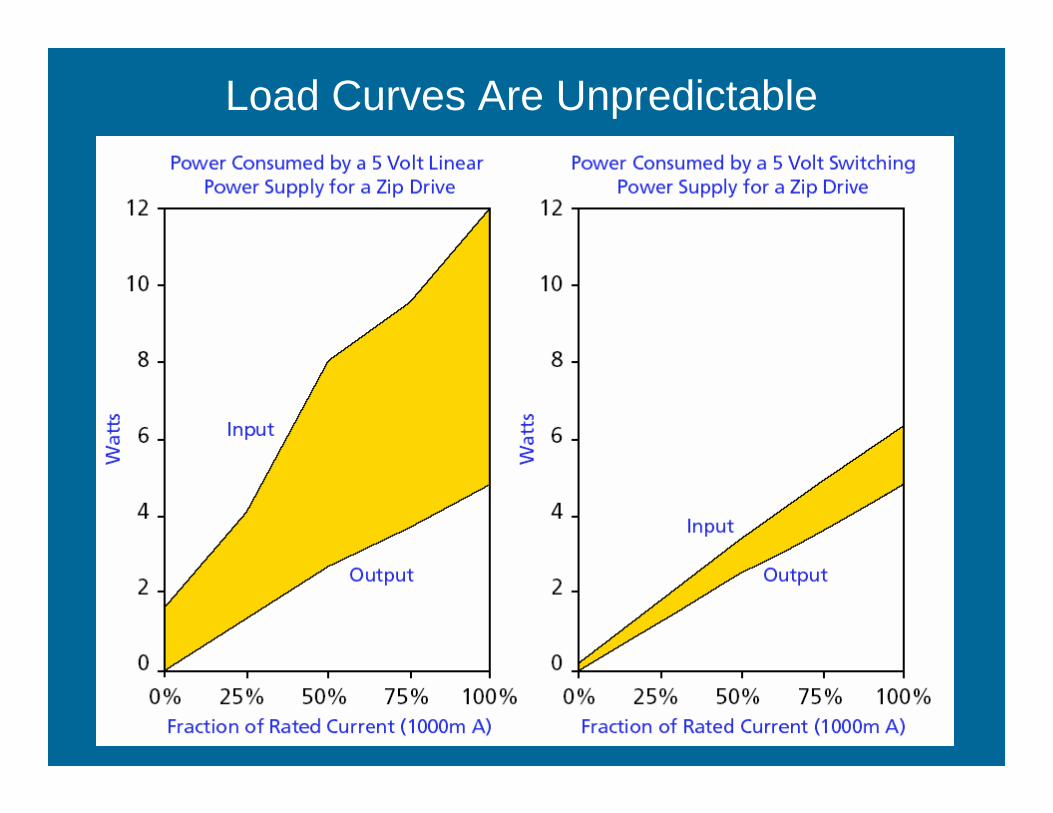
Load Curves Are Unpredictable

Sample Test
Report

0%
20%
40%
60%
80%
100%
0 100 120 140 160
Effic
ienc
y
U.S.
Range of Average Efficiency in Active Mode
20 40 60 80
Nameplate Output Power (watts)
China
Australia
New data

0%
20%
40%
60%
80%
100%
0 100 120 140 16
Effic
ienc
y
Distribution of External Power Supplies and Proposed ENERGY STAR Active Mode Specification
20 40 60 80
Nameplate Output Power (watts)
China Australia U.S. New data Proposed Active Mode Spec

0% 0 1 2 3 4 5 6 7 8 9
)
Distribution of External Power Supplies and Proposed ENERGY STAR Active Mode Specification: 10 Watts and Less
20%
40%
60%
80%
100%
10
Nameplate Output Power (watts
Effic
ienc
y
China
Australia
U.S.
New data
Proposed Active Mode Spec

0.0
0.5
1.0
1.5
2.0
2.5
3.0
3.5
4.0
0 100 125 150 175
Mea
sure
d N
o Lo
ad P
ower
(ac
wat
ts)
U.S.A.
25 50 75 Nameplate Output Power (dc watts)
China
Australia
New data

0.0
0.5
1.0
1.5
2.0
2.5
3.0
3.5
4.0
0 100 125 150 175
Mea
sure
d N
o Lo
ad P
ower
(ac
wat
ts)
(1) (2)
Revised No Load Specification Proposal
25 50 75 Nameplate Output Power (dc watts)
China Australia U.S.A. New data Proposed No Load Max PowerProposed No Load Max Power

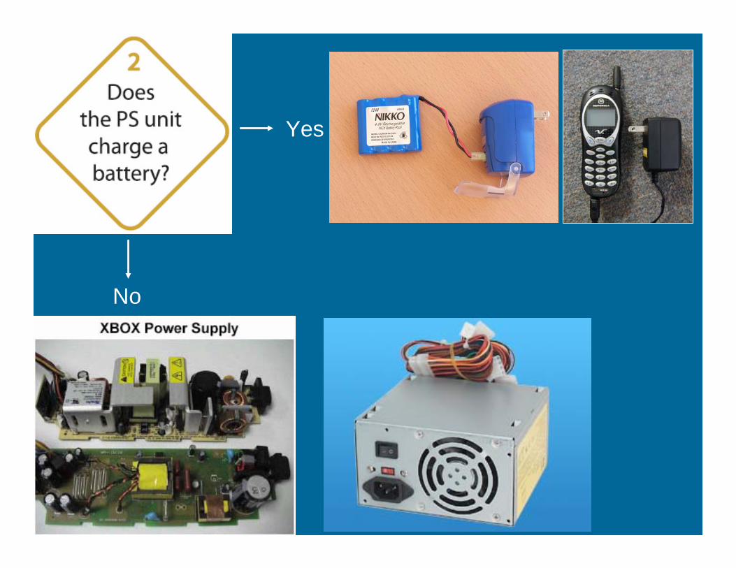
It Is Easier to Spot the Difference Between an External Power Supply and a Battery Charger In
Some Products than Others

Most Products Connected to External Power Supplies Are Battery Chargers
• external power supplies are battery chargers
•
phones, cordless shavers, PDAs, laptops •
answering machines, computer speakers, faxes and modems
Approximately 60% of products connected to
Examples of EPS where dc output is used to charge batteries - cellular and cordless
Examples of EPS with no battery charging

Pow
er C
onsu
mpt
ion
Functionality
Ac-dc power
conversion
trickle charge
Indicator light
Multiple battery
charge monitoring, multiple voltage capability,
Defining Power Supply/Battery Charger Differences
Constant
chemistry capability
Thermal and state-of-
charge meter or display

Circuitry Location Is Less Important than Circuitry Function and Power Consumption
Ac-dc power conversion charging charging
Ac-dc power conversion
Battery packBasic battery Basic battery


OR

Defining Differences Between External Power Supplies and Cosmetically Similar Battery Chargers

No
Yes
Yes
No

Yes
No

No
Yes

Yes
No

Yes
No
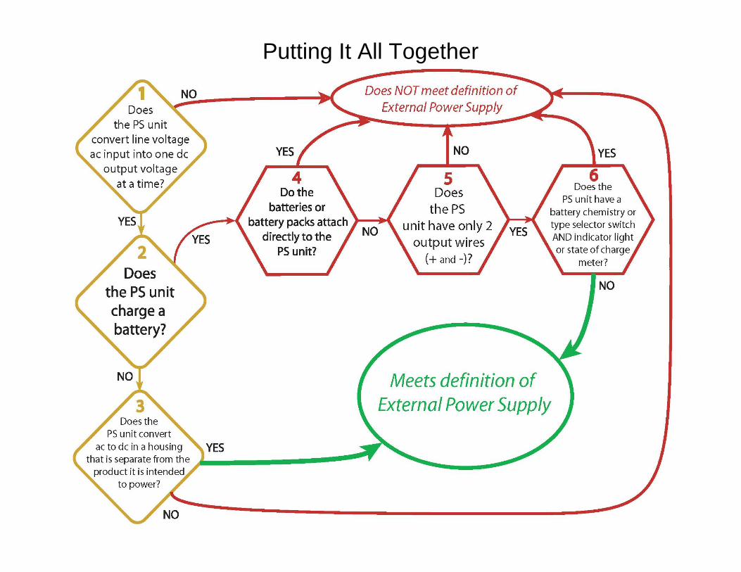
Putting It All Together