extension of an automatic building extraction technique to
TRANSCRIPT

HAL Id: halshs-00264836https://halshs.archives-ouvertes.fr/halshs-00264836
Submitted on 19 May 2008
HAL is a multi-disciplinary open accessarchive for the deposit and dissemination of sci-entific research documents, whether they are pub-lished or not. The documents may come fromteaching and research institutions in France orabroad, or from public or private research centers.
L’archive ouverte pluridisciplinaire HAL, estdestinée au dépôt et à la diffusion de documentsscientifiques de niveau recherche, publiés ou non,émanant des établissements d’enseignement et derecherche français ou étrangers, des laboratoirespublics ou privés.
Extension of an automatic building extraction techniqueto airborne laser scanner data containing damaged
buildingsFayez Tarsha-Kurdi, M. Rehor, Tania Landes, Pierre Grussenmeyer, H.P
Baehr
To cite this version:Fayez Tarsha-Kurdi, M. Rehor, Tania Landes, Pierre Grussenmeyer, H.P Baehr. Extension of anautomatic building extraction technique to airborne laser scanner data containing damaged buildings.ISPRS Hannover Workshop, Germany, High-Resolution Earth Imaging for Geospatial Information,Jun 2007, Germany. pp.1-6. �halshs-00264836�

EXTENSION OF AN AUTOMATIC BUILDING EXTRACTION TECHNIQUE TO
AIRBORNE LASER SCANNER DATA CONTAINING DAMAGED BUILDINGS
F. Tarsha-Kurdi a, M. Rehor b, T. Landes a, P. Grussenmeyer a, H.-P. Bähr b
a Photogrammetry and Geomatics Group, MAP-PAGE UMR 694 – INSA de Strasbourg, 67000 Strasbourg, France -
(fayez.tarshakurdi, tania.landes, pierre.grussenmeyer)@insa-strasbourg.fr b Institute of Photogrammetry and Remote Sensing (IPF), Universität Karlsruhe (TH), Englerstr. 7, 76128 Karlsruhe,
Germany – (miriam.rehor, hans-peter.baehr)@ipf.uni-karlsruhe.de
KEY WORDS: Laser scanning, LIDAR, Point Cloud, DSM, Segmentation, Extraction, Building, Disaster
ABSTRACT:
Airborne laser scanning systems generate 3-dimensional point clouds of high density and irregular spacing. These data consist of
multiple returns coming from terrain, buildings, and vegetation. The major difficulty is the extraction of object categories, usually
buildings. In the field of disaster management, the detection of building damages plays an important role. Therefore, the question
arises, if damaged buildings can also be detected by a method developed for the automatic extraction of buildings. Another purpose
of this study is to extend and test an automatic building detection method developed initially for first echo laser scanner data on data
captured in first and last echo. In order to answer these two questions, two institutes share their data and knowledge: the Institute of
Photogrammetry and Remote Sensing (IPF, Universität Karlsruhe (TH), Germany) and the MAP-PAGE team (INSA de Strasbourg,
France). The used 3D LIDAR data was captured over an area containing undamaged and damaged buildings. The results achieved
for every single processing step by applying the original and the extended algorithm to the data are presented, analysed and
compared. It is pointed out which buildings can be extracted by which algorithm and why some buildings remain undetected.
1. INTRODUCTION
The airborne laser scanning technique represents a recent
technology based on fast acquisition of dense 3D data and
allowing the automation of data processing. Many applications
have begun to find their way towards LIDAR data such as
urban planning, GIS databases, mobile communication, and 3D
city modelling or virtual reality. Among the LIDAR application
domain, automatic building extraction and modelling have
important positions. The former permits detecting building
point clouds automatically from the total point cloud. During
automatic building modelling, 3D building models which are
composed of sets of intersected planes and edges are calculated.
It has to be mentioned that a LIDAR system has the ability to
capture many returns for every laser beam. For each of these
returns the laser system generates one point cloud. So at the end
of laser scanning many point clouds are provided whereas each
one represents one return (Alharthy and Bethel, 2002). The
most important of these point clouds are those belonging to the
first and last returns. They are called first and last echo.
Generally, the difference between first and last echo allows
eliminating the vegetation from a digital surface model (DSM)
during building extraction operations (Tarsha-Kurdi et al.,
2006; Alharthy and Bethel, 2004; Tóvári and Vögtle, 2004).
But in most cases, either last echo is less accurate than first
echo (Hyyppä et al., 2005; Yu et al., 2005) or it is not separable
from first echo (Pfeifer et al., 1999; Wotruba et al., 2005).
Nowadays, disaster management becomes more and more
important. Due to the fast collection of height data, laser
scanning is particularly suitable for the extensive coverage of
information about the damage situation after disasters like
earthquakes. As a consequence, damage analyses can be carried
out rapidly after the occurrence of a disaster. This in turn can
support rescue activities because the required resources depend
among other things on the damage types appearing at the
affected buildings (Schweier and Markus, 2004). Therefore, one
project within the Collaborative Research Centre 461: “Strong
Earthquakes: A Challenge for Geosciences and Civil
Engineering” deals with the development of techniques for
automatic determination of damage classes occurring at
buildings in consequence of earthquakes (Rehor and Bähr,
2006). The project is sponsored by the Deutsche
Forschungsgemeinschaft (German Research Foundation) and
worked on by the Institute of Photogrammetry and Remote
Sensing (IPF, Universität Karlsruhe (TH), Germany).
The classification of building damages will normally be based
on the comparison of pre- and post-event building models. If no
pre-event model is available, it might be helpful to know which
buildings can be detected by a building extraction method based
on laser scanning data. It is assumed that damaged buildings
can only be recognised as buildings if their roof structure is
preserved. So, if this presumption proves true, damage types
like outspread multi layer collapse or any heap of debris type
can be excluded for all buildings identified by the mentioned
method. And although no statement can be made, if the
buildings are damaged or not, it might be a useful hint for
decision makers.
Due to these remarks, the IPF and the MAP-PAGE team (INSA
de Strasbourg, France) are working together to answer the
following two questions:
1.
2.
What are the benefits provided by the simultaneous
use of first and last echo in an automatic building
extraction operation?
Can damaged buildings be detected by a method
developed for the automatic extraction of
(undamaged) buildings?

2. RELATED WORK
Regarding automatic building extraction from LIDAR data, the
proposed approaches can be divided into two families according
to their processing manners. The first family presents
approaches which are mainly based on images produced by
interpolation and/or segmentation of the original point cloud. In
this case, segmentation mostly means the generation of objects
composed of similar pixels. The second family contains
approaches trying to concentrate processing on point level. In
this context, segmentation means the discrimination of several
clusters in a point cloud. Another way to classify the automatic
building extraction approaches can be achieved according to the
used data: either they are using only first echo or first and last
echo together.
This paper focuses on the latter classification, because its aim is
to analyse if the consideration of two echoes is more
appropriate than only one echo for the detection of damaged or
undamaged buildings. In the approach family which uses first
echo only, many methods are envisaged. The methods proposed
by (Tarsha-Kurdi et al., 2006; Tarsha-Kurdi et al., 2007)
suggest to superimpose the point cloud with the DSM and to
analyse topological relationships between points located in the
same cell for separating vegetation from buildings. (Whang and
Tseng, 2004) propose the use of a segmentation based on an
octree structure. Furthermore, the use of interpolation methods
such as the linear prediction method (Kraus and Pfeifer, 1998;
Rottensteiner and Briese, 2002) or the 3D surface detection
(Lee and Schenk, 2002) can be cited.
In the second approach family which uses first and last echoes
together, digital image processing techniques are employed, e.g.
remote sensing classification methods (Tóvári and Vögtle,
2004; Lohmann and Jacobsen, 2004). In this category, two
directions are followed: the first one considers the DSMs
generated from first and last echo as two separate bands; the
second one uses the first/last echo difference matrix as one
single band. Another method developed by (Alharthy and
Bethel, 2002) proposes the use of a gradient filter and the
first/last echo difference matrix to eliminate vegetation.
Concerning the detection of damaged buildings after disasters,
the use of laser scanning data is proposed in several
publications, e. g. (Dash et al., 2004), (Vu et al., 2004a), (Vu et
al., 2004b), (Murakami et al., 1999). But until now change
detection methods based on LIDAR data have never been tested
on data containing real damaged buildings.
3. DATA
The test site is a training field of the Swiss Military Disaster
Relief located in the surroundings of Geneva (Figure 1). It is
used for training search and rescue activities in case of
catastrophic events and has a size of about 500 m × 800 m. It is
situated in a valley and belongs to a hard-relief rural region.
The particularity of the test area is that both undamaged and
damaged buildings are located on it (Figure 1). Some
characteristics of the buildings marked in Figure 1 are
summarised in Table 2. The areas encircled in blue characterise
damages like outspread multi layer collapse or different heap of
debris types, whereas areas marked in red emphasise damage
types like pancake collapse or inclined planes. As already
mentioned in section 1, only the latter damage types are of
interest since it is foreseeable that only such kinds of building
damages might be identified by an automatic building detection
procedure.
In 2004 laser scanning data were acquired on the test site for the
project within the Collaborative Research Centre 461
mentioned above. Table 1 contains some more information
about the data.
For testing the developed algorithms, the first and last echo
point clouds are considered. Furthermore, they enter into the
processing chain in their original form (point cloud) as well as
in their interpolated form (DSM).
Figure 1: Aerial image of the test area (in red: undamaged
buildings, pancake collapses, inclined planes; in
blue: heaps of debris, outspread multi layer collapse)
Acqui-
sition Sensor
Flying
height
Laser
pulse rate
Scan
width Echo
June
2004
TopoSys
Falcon II900 m 83 kHz 14.3°
first and
last
Table 1: Laser scanning data characteristics
4. THE ALGORITHMS
In automatic building extraction approaches, it is important to
analyse the benefit provided by the simultaneous use of first
and last echo in comparison with other methods using first echo
only. In order to achieve this purpose, the method suggested by
(Tarsha-Kurdi et al., 2006) which is based on first echo only
has been tested by means of the available data. Moreover, this
method has been extended to the use of both first and last
echoes. Finally, a comparison of the results obtained by both
methods is carried out.
4.1 Building detection using first echo only
As aforementioned, the method developed by (Tarsha-Kurdi et
al., 2006) is initially based on the first echo point cloud and the
DSM derived from it by nearest neighbour interpolation. The

last echo point cloud is not included in the workflow because it
is not always available with a sufficient reliability. The
approach consists of two steps: the segmentation of the point
cloud into terrain and off-terrain points, and then the extraction
of a building subclass from the off-terrain class.
The first step uses only the DSM as input data. Furthermore two
thresholds Δh and S are introduced, where Δh represents the
minimum height difference between terrain and off-terrain and
S typifies the minimal acceptable building surface. In order to
carry out this processing step, successive procedures are
achieved. Firstly, the borders of the off-terrain class are
detected using gradient filters and the threshold Δh. Secondly,
the bodies of the segment borders created previously are filled
by means of an algorithm which uses a 3 × 3 moving window
passing over the binary matrix containing the off-terrain
borders.
The second stage consists in the discrimination of the off-terrain
into vegetation and buildings. The input data of this step are the
calculated off-terrain mask containing all off-terrain objects, the
DSM and the original point cloud. This operation starts with the
detection of the building kernels by studying the spatial
topological relationships between points included in the same
cell of the DSM. Afterwards a region growing algorithm is
carried out starting from these extracted kernels to identify the
remaining building points. During this operation based on the
DSM only, two thresholds S and Δhroof are adopted. The first
one (S) represents again the minimal acceptable building
surface and the other one (Δhroof) typifies the maximum allowed
roof slope converted into a height difference by means of the
DSM sampling value p (p=1 m) (Tarsha-Kurdi et al., 2007).
4.2
4.2.1
Building detection using first and last echo
In this section, the algorithm described previously is extended
to the use of first and last echo. Before presenting the main
elements of the extended approach, it is necessary to define the
DIF matrix.
Calculation and analysis of the DIF matrix: The DIF
matrix expresses the difference between first and last echo and
is calculated by the subtraction of the two DSMs (eq. 1).
DIF = DSMFE – DSMLE (1)
where DSMFE = DSM generated from first echo
DSMLE = DSM generated from last echo
Figure 2 shows the DIF matrix and emphasizes that the values
of the pixels are located between –20 m and +20 m. The
majority of the non-null pixels have positive values. This
confirms the fact that the first echo captures points located on a
higher altitude than the last echo.
By analysing the DIF matrix values in more detail three main
intervals can be extracted:
1. Pixels with positive values (10.7 % of the total
number). They represent vegetation and building
borders. Sometimes they represent noise.
2. Pixels with values equal zero (86.0 %). They
represent terrain and building bodies. Only a few
points are located in vegetated areas.
3. Pixels with negative values (3.3 %).
Figure 2: Visualisation of the DIF matrix
The presence of the last kind of pixels can be explained easily.
A pixel of negative value does not result from the same laser
beam in first and last echo. For example, Figure 3 presents three
laser beams for which the first echo is displayed in red and the
last one in blue. The resulting pixel in the produced DSM is
shown in the lower part of the figure. The cells A and B belong
to the DSM. Generally, if two points belong to the same DSM
cell and have the same X and Y coordinates, then the DSM cell
value is equal to the mean altitude value of the two points. If ZFi
and ZLi represent the altitudes of the first and last reflection of
laser beam number i, then the values of the cells A and B in
DSMFE and DSMLE are calculated as follows:
DSMFE (A) = (ZF1 + ZF3) / 2, (2)
DSMFE (B) = ZF2, (3)
DSMLE (A) = ZL3, (4)
DSMLE (B) = (ZL1 + ZL2) / 2. (5)
Consequently, the values of these cells in the DIF matrix are:
DIF (A) = (ZF1 + ZF3) / 2 - ZL3 > 0, (6)
DIF (B) = ZF2 - (ZL1 + ZL2) / 2 < 0. (7)
Therefore, it is clear that DIF (B) is inferior to zero. Moreover,
the accuracy difference between the first and the last echo
sometimes generates negative values in the DIF matrix.
Figure 3: Explanation of negative values in the DIF matrix.
First echo is marked in red and last echo in blue.
4.2.2 Extension of the algorithm to the use of first and
last echo: Like the original approach, this procedure starts with
the segmentation of terrain and off-terrain points. Since this
processing step is identical to the first step of the original
algorithm it is not explained again in this part.
The second step of the process consists in the discrimination of
the off-terrain class into the subclasses vegetation and
buildings. This is the point where the modified approach differs
from the original one. In this adapted and extended method,
first of all, the difference between first and last echo DSM is
calculated and provides the DIF matrix (as shown in the
previous section). The DIF matrix is an indicator for the nature
of the pixels (vegetation or building) and is consequently useful
for the elimination of a large part of vegetation. Indeed, as
already mentioned, pixels having values equal to zero in the
DIF matrix represent terrain and building bodies; furthermore,
pixels with other values represent vegetation and building
borders. So the off-terrain pixels corresponding to non-zero
pixels of the DIF matrix have to be eliminated. In order to
remove the remaining vegetation segments considered as noise,
the threshold S limiting the minimal acceptable building surface
is introduced. In such a manner the noisy building kernel mask
can be cleaned and then the remaining segments represent the
building kernels. The last step of this building extraction task
consists in completing the building kernels with the surrounding
pixels lost previously. This is done with the use of a normalised
first echo DSM on which the same region growing algorithm is
applied as it is used during the original approach (see section
4.1). It works on the eight neighbouring height differences
(Δhroof). A last filter operation erases the remaining segments by
regarding the threshold S again.
5. RESULTS AND COMPARISON OF THE TWO
APPROACHES
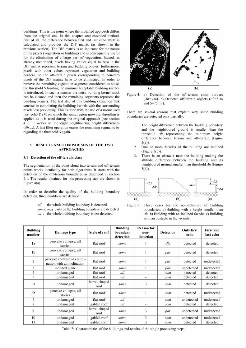
5.1 Detection of the off-terrain class
The segmentation of the point cloud into terrain and off-terrain
points works identically for both algorithms. It starts with the
detection of the off-terrain boundaries as described in section
4.1. The results obtained for this processing step are shown in
Figure 4(a).
In order to describe the quality of the building boundary
detection, three qualifiers are defined:
all: the whole building boundary is detected
some: only parts of the building boundary are detected
any: the whole building boundary is not detected
(a) (b)
Figure 4: a) Detection of the off-terrain class borders
(Δh=3 m). b) Detected off-terrain objects (Δh=3 m
and S=75 m²).
There are several reasons that explain why some building
boundaries are detected only partially:
1. The height difference between the building boundary
and the neighboured ground is smaller than the
threshold Δh representing the minimum height
difference between terrain and off-terrain (Figure
5(a)).
2. One or more facades of the building are inclined
(Figure 5(b)).
3. There is an obstacle near the building making the
altitude difference between the building and its
neighboured ground smaller than threshold Δh (Figure
5(c)).
(a) (b) (c)
Figure 5: Three cases for the non-detection of building
boundaries: a) Building with a height smaller than
Δh. b) Building with an inclined facade. c) Building
with an obstacle in the vicinity.
Building
number Damage type Style of roof
Building
boundary
detection
Reason for
non-
detection
Detection Only first
echo
First and
last echo
1a pancake collapse, all
stories flat roof some 1 dis detected detected
1b pancake collapse, all
stories flat roof some 1 par detected detected
2 pancake collapse in combi-
nation with an inclination flat roof some 1 par detected undetected
3 inclined plane flat roof some 1 par undetected undetected
4 undamaged flat roof all - com detected detected
5 undamaged flat roof all - com detected detected
6a undamaged barrel-shaped
roof some 3 com detected detected
6b pancake collapse, all
stories flat roof some 1 com detected undetected
7 undamaged flat roof all - com undetected undetected
8 undamaged gabled roof all - com detected detected
9 undamaged barrel-shaped
roof some 3 par undetected undetected
10 undamaged gabled roof some 3 com undetected undetected
11 undamaged gabled roof some 3 com detected detected
Table 2: Characteristics of the buildings and results of the single processing steps

Table 2 presents the results of the boundary detection. It can be
seen that the boundaries of 4 buildings (all undamaged) are
detected completely, whereas the boundaries of 9 buildings (5
damaged and 4 undamaged) are detected only partially.
After the off-terrain boundaries, the bodies of the off-terrain
objects are determined (Figure 4(b)). For describing the quality
of the building detection during the extraction of the off-terrain
class the following three qualifiers are used:
com: building is detected completely
par: building is detected partially
dis: building is not detected at all
The results of this processing step are also summarised in Table
2. It can be noticed that 8 buildings are detected entirely. Four
of them correspond to the buildings for which the whole
boundary was extracted in the previous step.
The buildings 6a, 6b, 10 and 11 are determined because the
missing boundary parts are small enough. As a consequence, it
can be pointed out that the results of this step are directly
correlated with the results of the off-terrain boundary detection.
If the boundary of a building is completely detected, the whole
building body will be extracted as well. Else its detection is
dependent on the orientation of the building in relation to the
direction of the moving window.
5.2 Extraction of buildings from the off-terrain class
Figures 6(a) and 6(b) show the results obtained by using the
original and the extended algorithm, respectively. Table 2 gives
an overview of the final results.
(a) (b)
Figure 6: a) Building detection using DSM and first echo
only. b) Building detection using first and last echo.
If the original approach using first echo only is applied to the
test dataset, 9 buildings are detected correctly, whereas 4
buildings remain undetected. That means that 4 of the 5
damaged and 5 of the 8 undamaged buildings can be found. The
reason for the non-detection of the buildings 3, 7, 9 and 10 is
their size. Their building kernels determined during the second
step of the process (see section 4.1) are smaller than threshold S
standing for the minimal building size. That is the case because
there are details and noise on the roof surfaces. Furthermore,
the nature of the building roofs plays an important role at the
extraction of buildings, because the algorithms act on the
assumption that roofs are generally composed of planar
surfaces. If this assumption is not fulfilled, like e.g. for building
9, the algorithms fail for the concerning building. Furthermore,
there are two cases in which misclassifications occur i.e.
vegetation is classified as building. They are marked in Figure
6(a) with blue circles.
The use of the extended method introducing first and last echo
as input data results in the detection of the buildings 1a, 1b, 4,
5, 6a, 8 and 11. That means that besides the buildings which
have not been extracted by the original algorithm the buildings
2 and 6b stay undetected additionally. The buildings 3, 7, 9 and
10 are not identified because of the same reasons as described
above for the other method. Concerning the buildings 2 and 6b
it has to be mentioned that they are damaged. In the case of
damaged buildings there is the risk of eliminating
supplementary points over the building roof if the DIF matrix is
used for the elimination of vegetation. Consequently, the
building kernels are smaller than those obtained by using first
echo data only.
Building 1a is extracted by both methods although it has not
been detected as off-terrain object in the first step of the
algorithms (see section 5.1). For understanding this
phenomenon, it has to be mentioned that there are two
possibilities for the input data of the region growing algorithm:
1. The region growing algorithm is based on the total
DSM. In this case the possibility exists to complete
the disappeared parts of only partially detected
buildings. At the same time, if the used height
difference threshold Δhroof is relatively big and the
terrain and off-terrain separation threshold Δh is
relatively small, the risk exists that all points of the
DSM are detected as off-terrain.
2. The region growing algorithm is applied on the off-
terrain class. In this case there is not any risk, but the
partially detected buildings cannot be completed.
In the studied examples, the region growing algorithm is based
on the total DSM, because the used height difference threshold
Δhroof was small (Δhroof=0.35 m). Now it is obvious that building
1a is correctly detected since it is adjacent to building 1b.
6. CONCLUSION AND FUTURE WORK
It has to be noted that the results obtained by using first echo
only are more satisfactory than those achieved by using both
first and last echo, since the number of buildings detected by
this segmentation is higher (see Figures 6(a) and 6(b), Table 2).
On the other hand, the obtained results achieved by the
extended algorithm are more satisfying in areas where the
proportion of vegetation is high. Consequently, in general case,
if both echoes are available, it would be judicious to carry out
the calculation by applying both algorithms and by preserving
the union of the images extracted in this way. However, in the
presented example no improvement could be achieved by
generating the union of the two images because the extended
method does not detect additional buildings. Furthermore, the
vegetation classified as buildings by the original algorithm
would not be eliminated.
It has been shown in which cases undamaged buildings as well
as damaged buildings can be detected by the developed
approaches. To recapitulate, it can be said that the results
depend strongly on the thresholds used for the minimal height
differences and the minimum building surfaces. As a
consequence, buildings lower than the height difference

threshold Δh or smaller than the minimum building surface S
cannot be identified, no matter if they are damaged or not.
Therefore, damaged buildings can only be detected if they
exceed a certain height. A further condition for their recognition
is that the roof structure is preserved and that its slope is lower
than the threshold value of the maximum allowed roof slope
(Δhroof). So the assumption was confirmed that only buildings
suffered by damage types like pancake collapses, inclined
planes or overhanging elements can be extracted. In contrary
damage types like all heaps of debris types or outspread multi
layer collapses remain undetected.
In the near future, both institutes will follow up their research in
order to construct 3D building models automatically allowing
the realisation, classification and quantification of the total
building damages. For this purpose, a terrestrial laser scanning
campaign was carried out on the test area in March 2007. On
the one hand, it shall be used to confirm these results and on the
other hand, it will provide useful data for completing the 3D
models of the buildings.
ACKNOWLEDGEMENTS
The presented work has been funded by the Deutsche
Forschungsgemeinschaft (DFG) as part of the Collaborative
Research Centre (CRC) 461: “Strong Earthquakes”. The
authors would like to thank the Swiss Disaster Relief
Coordination and Control Centre DDPS for providing their
facilities.
REFERENCES
Alharthy, A. and Bethel, J., 2002. Heuristic filtering and 3d
feature extraction from LIDAR data. In: International Archives
of Photogrammetry and Remote Sensing (IAPRS), Graz,
Austria, Vol. XXXIV, Part 3A, ISSN 1682-1750, pp. 29-34.
Alharthy, A. and Bethel, J., 2004. Detailed building
reconstruction from airborne laser data using a moving surface
method. In: IAPRS, Istanbul, Turkey, Vol. XXXV, Part B3.
Dash, J., Steinle, E., Singh, R.P. and Bähr, H.-P., 2004.
Automatic building extraction from laser scanning data: an
input tool for disaster management. Advances in Space
Research, Volume 33, Issue 3, pp. 317-322.
Hyyppä, H., Yu, X., Hyyppä, J., Kaartinen, H., Kaasalainen, S.,
Honkavaara, E. and Rönnholm, P., 2005. Applicability of first
pulse derived digital terrain models for boreal studies. In: The
International Archives of Photogrammetry, Remote Sensing and
Spatial Information Sciences (IAPRSIS), Enschede, The
Netherlands, Vol. XXXVI, Part 3/W19, ISSN 1682-1777.
Kraus, K., and Pfeifer, N., 1998. Determination of terrain
models in wooded areas with airborne laser scanner data. ISPRS
Journal of Photogrammetry and Remote Sensing, 53, pp. 193-
203.
Lee., I. and Schenk., T., 2002. Perceptual organization of 3d
surface points. In: IAPRS, Graz, Austria, Vol. XXXIV, Part
3A, ISSN 1682-1750, pp. 193-198.
Lohmann, P., Koch, A. and Schaeffer, M., 2000. Approaches to
the filtering of laser scanner data. In: IAPRS, Amsterdam, The
Netherlands, Vol. XXXIII, Part B3/1, pp. 534-541.
Murakami, H., Nakagawa, K., Shibata, T. and Iwanami, E.,
1999. Potential of an airborne laser scanner system for change
detection of urban features and orthoimage development. In:
IAPRS, Stuttgart, Germany, Vol. XXXII, Part 4, pp. 422-427.
Pfeifer, N., Reiter, T., Briese, C. and Rieger, W., 1999.
Interpolation of high quality ground models from laser scanner
data in forested areas. In: IAPRS, La Jolla, California, USA,
Vol. XXXII, Part 3-W14, pp. 31-36.
Rehor, M. and Bähr, H.-P., 2006. Segmentation of damaged
buildings from laser scanning data. In: IAPRSIS, Bonn,
Germany, Vol. XXXVI, Part 3, ISSN 1682-1750, pp. 67-72.
Rottensteiner, F. and Briese, Ch., 2002. A new method for
building extraction in urban areas from high-resolution LIDAR
data. In: IAPRS, Graz, Austria, Vol. XXXIV, Part 3A, ISSN
1682-1750; pp. 295-301.
Schweier, C. and Markus, M., 2004. Assessment of the search
and rescue demand for individual buildings. In: Proceedings of
the 13th World Conference on Earthquake Engineering,
Vancouver, Canada.
Tarsha-Kurdi, F., Landes, T., Grussenmeyer, P. and Smigiel, E.,
2006. New approach for automatic detection of buildings in
airborne laser scanner data using first echo only. In: IAPRSIS,
Bonn, Germany, Vol. XXXVI, Part 3, ISSN 1682-1750, pp. 25-
30.
Tarsha-Kurdi, F., Landes, T. and Grussenmeyer, P., 2007. Joint
combination of point cloud and DSM for 3D building
reconstruction using airborne laser scanner data. 6th
International Symposium on Remote Sensing of Urban Areas,
Paris, France.
Tóvári, D. and Vögtle, T., 2004. Classification methods for 3D
objects in laserscanning data. In: IAPRS, Istanbul, Turkey, Vol.
XXXV, Part B3, ISSN 1682-1750.
Vu, T.T., Matsuoka, M. and Yamazaki, F., 2004a. LIDAR-
based Change Detection of Buildings in Dense Urban Area. In:
Proceedings of the International Geoscience and Remote
Sensing Symposium, IEEE, Anchorage, Alaska, USA, CD-
ROM, pp. 3412-3416.
Vu, T.T., Matsuoka, M. and Yamazaki, F., 2004b. Employment
of LIDAR in Disaster Assessment. In: Proceedings of the 2nd
International Workshop on Remote Sensing for Post-Disaster
Response, Newport Beach, California, USA.
Wotruba, L., Morsdorf, F., Meier, E. and Nüesch, N., 2005.
Assessment of sensor characteristics of an airborne laser
scanning using geometric reference targets. In: IAPRSIS,
Enschede, The Netherlands, Vol. XXXVI, Part 3/W19, ISSN
1682-1777.
Wang, M. and Tseng, Y.-H., 2004. Lidar data segmentation and
classification based on octree structure. In: IAPRS, Istanbul,
Turkey, Vol. XXXV, Part B3, ISSN 1682-1750.
Yu, X., Hyyppä, H., Kaartinen, H., Hyyppä, J., Ahokas, E. and
Kaasalainen, S., 2005. Applicability of first pulse derived
digital terrain models for boreal studies. In: IAPRSIS, Enschede,
The Netherlands, Vol. XXXVI, Part 3/W19, ISSN 1682-1777.