exposed linear encoder
DESCRIPTION
How to read and filter data from a heidenhein exposed optical linear encoderTRANSCRIPT
Exposed Linear Encoder
Title1b
Research Report
TITLE : Optical Linear Encoder measurement.
DOCUMENT NUMBER : 0000 ISSUE: 1
SYNOPSIS : This document describes Incremental linear encoder measurement. The report assesses different measurement methods, as well as advantages and disadvantages of this type of encoder.
KEYWORDS : Exposed, Linear, Incremental, Encoder, Optical, Interference pattern,
PREPARED BY : Jeran CloeteSAAO, Electronics
DATE : 03 October 2013
Exposed Linear Encoder
Title1b
ACRONYMS AND ABBREVIATIONS
MCU Microcontroller Unit
ISR Interrupt service routine
TCNT2 AVR microcontrollers timer2 register
Definitions
Microphonic /Microphony
The phenomenon whereby electronic devices transform mechanical vibrations into electrical signals, usually due to the piezoelectric effect.
Moire pattern A secondary pattern created when to similar or identical patterns are superimposed and shifted out of alignment.
Quadrature phase
Two signals phase shifted by ¼ of their period (90°) have a quadrature phase relationship.
Accuracy The proximity of the measure value and the actual value.
Error The actual difference between the measure value and the real world value.
Resolution The smallest change in the measured quantity to which the instrument will respond.
Displacement Change in position.
Distance The space between two positions.
Content
Exposed Linear Encoder
s
ABSTRACT:....................................................................................................................1
INTRODUCTION:............................................................................................................1
INVESTIGATIONS:..........................................................................................................2
1. Theoretical Considerations:................................................................................................................................21.1. Scanning Methods:........................................................................................................................................21.2. Interpolation:.................................................................................................................................................31.3. Linear Displacement Measurement:.............................................................................................................41.3.1. Measurement methods:.............................................................................................................................41.3.2. Vibration analyses:...................................................................................................................................4
2. Practical Considerations:....................................................................................................................................52.1. MCU Encoder connections:.....................................................................................................................52.2. Incremental Measurement Method:..............................................................................................................52.3. Vibration filtering..........................................................................................................................................62.4. Other sources of interference........................................................................................................................82.5. Encoder Mounting:........................................................................................................................................82.6. Absolute Reference Calculation:...................................................................................................................92.7. Microcontroller Considerations:.................................................................................................................102.8. Other interface methods:.............................................................................................................................10
3. CONCLUSIONS:.....................................................................................................11
4. RECOMMENDATIONS:..........................................................................................11
5. APPENDICES:........................................................................................................12
A. Data obtained from Heidenhain internal database:.......................................................................................12
B. Atmega328P C code:..........................................................................................................................................13
C. Heidenhain linear optical encoder brochure...................................................................................................17
D. HCTL2032 Quadrature decoder/interface IC.................................................................................................17
REFERENCES...............................................................................................................18
FIGURE 1 : HEIDENHAIN INTERFERNTIAL SCANNER, WITH REFLECTIVE GRATING [2]........2FIGURE 2: HEIDENHAIN IMAGING SCANNER [2]...............................................................................2FIGURE 3: QUADRATURE SIGNAL WITH 5 FOLD INTERPOLATION [3]........................................3FIGURE 4: QUADRATURE SIGNALS ILLUSTRATING OPPOSING DIRECTIONS OF TRAVEL [3]
...............................................................................................................................................................3FIGURE 5: GRATING BASED OPTICAL INERTIAL VIBRATION SENSOR.......................................4FIGURE 6: GRATING AND DISTANCE CODED REFERENCE MARKS ON HEIDENHAIN
GRATING STRIP..................................................................................................................................5FIGURE 7: QUADRATURE SIGNAL FILTERING ELECTRONICS AND TIMING DIAGRAM [4]....7

Exposed Linear Encoder
FIGURE 8: DIADURE PHASE GRATING WITH DISTANCE CODED REFERENCE MARKS...........9
5
Exposed Linear Encoder
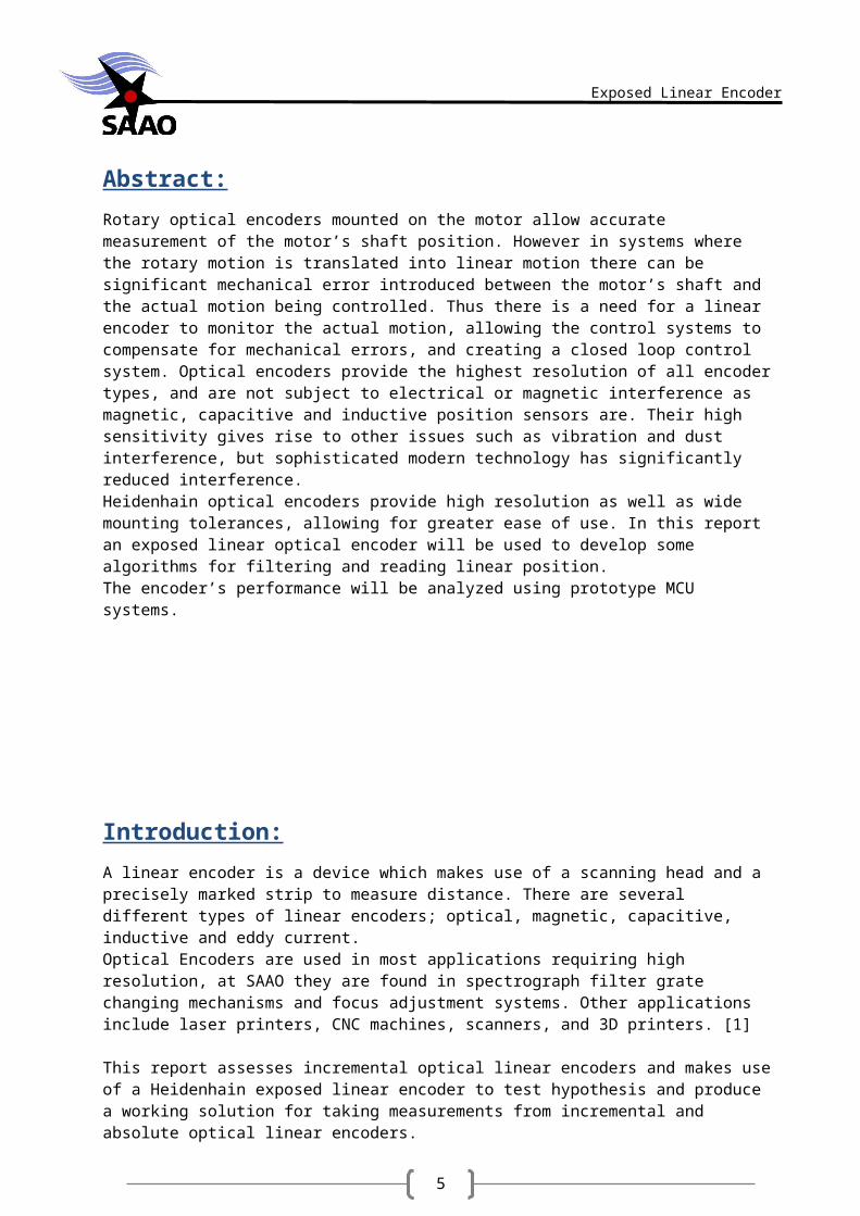
Abstract:
Rotary optical encoders mounted on the motor allow accurate measurement of the motor’s shaft position. However in systems where the rotary motion is translated into linear motion there can be significant mechanical error introduced between the motor’s shaft and the actual motion being controlled. Thus there is a need for a linear encoder to monitor the actual motion, allowing the control systems to compensate for mechanical errors, and creating a closed loop control system. Optical encoders provide the highest resolution of all encoder types, and are not subject to electrical or magnetic interference as magnetic, capacitive and inductive position sensors are. Their high sensitivity gives rise to other issues such as vibration and dust interference, but sophisticated modern technology has significantly reduced interference.Heidenhain optical encoders provide high resolution as well as wide mounting tolerances, allowing for greater ease of use. In this report an exposed linear optical encoder will be used to develop some algorithms for filtering and reading linear position.The encoder’s performance will be analyzed using prototype MCU systems.
Introduction:
A linear encoder is a device which makes use of a scanning head and a precisely marked strip to measure distance. There are several different types of linear encoders; optical, magnetic, capacitive, inductive and eddy current.Optical Encoders are used in most applications requiring high resolution, at SAAO they are found in spectrograph filter grate changing mechanisms and focus adjustment systems. Other applications include laser printers, CNC machines, scanners, and 3D printers. [1]
This report assesses incremental optical linear encoders and makes use of a Heidenhain exposed linear encoder to test hypothesis and produce a working solution for taking measurements from incremental and absolute optical linear encoders.
The principles outline in this report apply to any incremental quadrature output based encoder, although the absolute position measurement will vary depending on manufacturer and encoder type.
6
Exposed Linear Encoder
Investigations:
1. Theoretical Considerations:
1.1. Scanning Methods:
An optical encoder consists of a light source, one or more optical sensors, and an interfering grating. The grating is often placed above a reflective coating (usually aluminium) which allows the sensor and light source to be in one scanning head. The reflected light can be measured in 3 ways; by analysing the Moiré pattern, by calculations performed on a diffraction pattern, or by holographic analysis of the surface being scanned.
Heidenhain Linear position sensors utilize imaging scanning or interferential scanning.Imaging scanning is only suitable for gratings spaced wider than 10µm, and interferential scanning is used for gratings spaced 8µm, 4µm or less (this is because a narrower slit produces a wider diffraction). Interferential scanning produces an output which is more easily interpolated, allowing extremely high resolution.
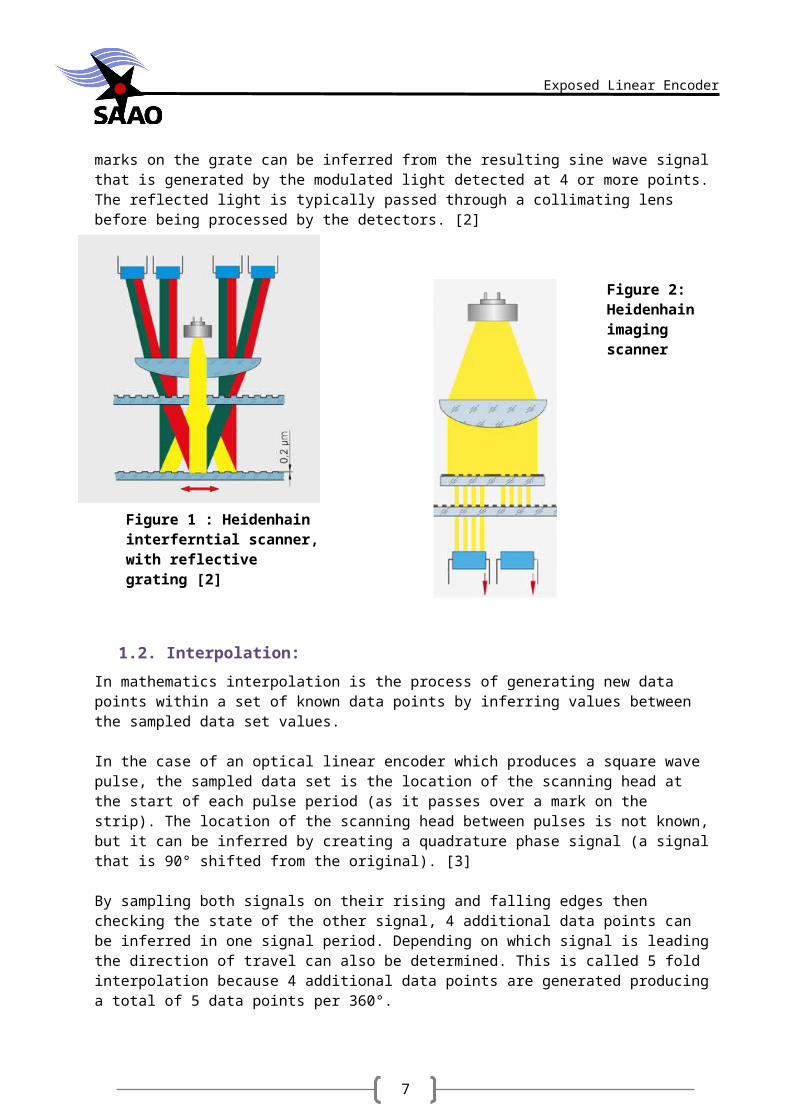
An imaging scanner has a reference grating fixed to the scanning head, it has the same grating period as the strip, and when it moves with respect to the strip the reflected or passed light is modulated.
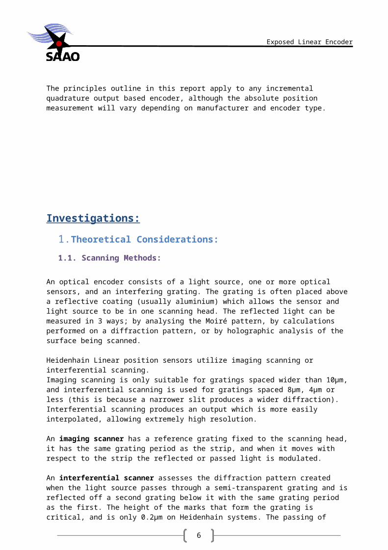
An interferential scanner assesses the diffraction pattern created when the light source passes through a semi-transparent grating and is reflected off a second grating below it with the same grating period as the first. The height of the marks that form the grating is critical, and is only 0.2µm on Heidenhain systems. The passing of marks on the grate can be inferred from the resulting sine wave signal that is generated by the modulated light detected at 4 or more points. The reflected light is typically passed through a collimating lens before being processed by the detectors. [2]
1.2. Interpolation:
In mathematics interpolation is the process of generating new data points within a set of known data points by inferring values between the sampled data set
Figure 1 : Heidenhain interferntial scanner, with reflective grating [2]
Figure 2: Heidenhain imaging scanner [2]
7
Exposed Linear Encoder
In the case of an optical linear encoder which produces a square wave pulse, the sampled data set is the location of the scanning head at the start of each pulse period (as it passes over a mark on the strip). The location of the scanning head between pulses is not known, but it can be inferred by creating a quadrature phase signal (a signal that is 90° shifted from the original). [3]
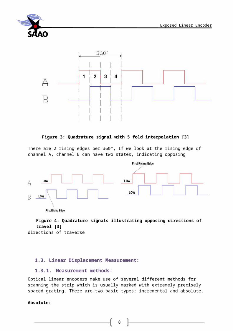
By sampling both signals on their rising and falling edges then checking the state of the other signal, 4 additional data points can be inferred in one signal period. Depending on which signal is leading the direction of travel can also be determined. This is called 5 fold interpolation because 4 additional data points are generated producing a total of 5 data points per 360°.
Figure 3: Quadrature signal with 5 fold interpolation [3]
There are 2 rising edges per 360°, If we look at the rising edge of channel A, channel B can have two states, indicating opposing directions of traverse.
Figure 4: Quadrature signals illustrating opposing directions of travel [3]
8
Exposed Linear Encoder
1.3. Linear Displacement Measurement:
1.3.1. Measurement methods:
Optical linear encoders make use of several different methods for scanning the strip which is usually marked with extremely precisely spaced grating. There are two basic types; incremental and absolute.
Absolute:
In absolute encoders the strip has several unique tracks each bearing a digital code (marked in lines of varying lengths). When the encoder moves a different digital sequence is generated for each position.
Incremental:
In incremental type encoders there are usually two tracks, one contains the closely spaced measurement marks, and the other reference marks. The absolute position is determined by counting the measurement marks between reference marks, and the position thereafter is determined purely by counting marks. These require the scanning head to traverse a short distance (at least the distance between 2 consecutive reference marks) before an absolute position is known. This is called distance coded reference marks (the alternative being only one reference mark at the centre point of the strip). Distance coded reference marks are unequally spaced so that the number of increments between reference marks can be used to determine absolute position by calculation.
1.3.2. Vibration analyses:
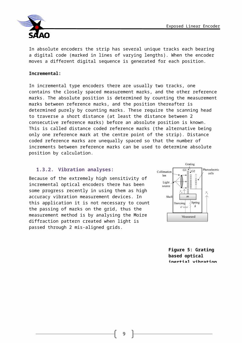
Because of the extremely high sensitivity of incremental optical encoders there has been some progress recently in using them as high accuracy vibration measurement devices. In this application it is not necessary to count the passing of marks on the grid, thus the measurement method is by analysing the Moire diffraction pattern created when light is passed through 2 mis-aligned grids.
2. Practical Considerations:
2.1. MCU Encoder connections:
The MCU at hand is an Arduino Uno which has only 2 interrupt pins, therefore the second quadrature signal will only be used to determine direction of motion. The first quadrature signal
Figure 5: Grating based optical inertial vibration sensor
9
Exposed Linear Encoder
and the reference signal will be connected to the interrupts to track incremental position and allow the MCU to precisely monitor the passing of reference marks.
Encoder pin MCU pin DescriptionUa1 Interrupt 0 Quadrature signal 1Ua2 Digital pin 4 Quadrature signal 2Ua0 Interrupt 1 Reference trackUp, Sensor 5V 5V0V, Sensor 0V GNDUs Digital pin 5 Error signal
Table 1: Microcontroller interface to optical linear sensor
2.2. Incremental Measurement Method:
The microcontroller will attempt to keep track of the displacement of the encoder head by counting pulses. The position will be determined by calculation every time a distance coded reference mark is passed. Between reference marks the distance from the end of the strip is incremented by each pulse.
The LIF171C Encoder head produces a signal period of 0.8µm (after 5 fold electronic interpolation), thus each pulse indicates a change in position of 0.8µm and every 5 pulses indicates the passing of a single mark on the strip’s grating. Performing 4 fold evaluation of the phase shifted outputs allows you to increase the resolution to 0.2µm.Unfortunately since a motion of 0.8µm causes the scanning head to output a pulse, high resolution incremental encoders are highly susceptible to vibration induced errors.
2.3. Vibration filtering.
The encoder strip’s grating period is 8µm, thus a change in output signal level is produced every 4µm. After 5 fold interpolation a change of 4µm produces 5 pulses.
Therefore any vibration with a frequency below 1
4 µm=250kHz will produce an output, because
one oscillation will move the scanning head back and forth over more than 4µm causing the sensors to detect a change. For low frequency vibrations the microcontroller interrupts can keep
Figure 6: Grating and distance coded reference marks on Heidenhain grating strip

10
Exposed Linear Encoder
up with the oscillations, incrementing and decrementing the count as the scanning head moves back and forth across the marks. The high frequency vibrations cause the microcontroller to count arbitrary transitions as fast as the interrupt can track the signal, which results in more counts in one direction than the other and the position is lost. This is exacerbated by the 5 fold interpolation which effectively multiplies the physical vibrating frequency by 5.Heidenhain indicates that their optical encoders cannot track motion with acceleration above 11 /ms or 6m/s. Machine vibration can also interfere during fast motion, so comprehensive tests should be done on a mounted system.
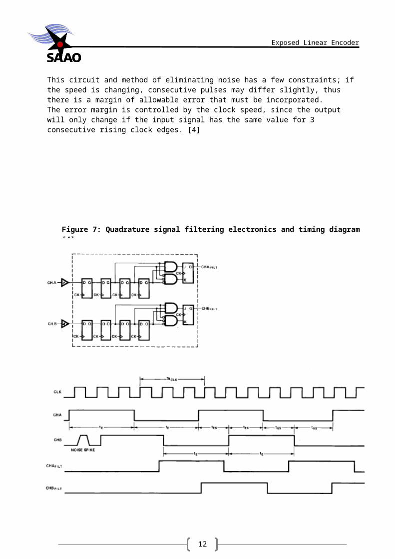
Unfortunately a simple low pass filter will not work because the noise induced on the digital signal is actually measurement of the transient physical motion, removing transitions that occur too close to others may filter increments caused by permanent motion of the scanning head. Additionally the frequency of the output signal increases when the scanning head is moving faster.To solve this problem it is necessary to keep track of the pulse width of both channels of the quadrature output, then compare each count’s pulse width with a few preceding pulses, if the width is significantly different the count is ignored. This can be implemented electronically with the circuit in figure 7.This circuit and method of eliminating noise has a few constraints; if the speed is changing, consecutive pulses may differ slightly, thus there is a margin of allowable error that must be incorporated.The error margin is controlled by the clock speed, since the output will only change if the input signal has the same value for 3 consecutive rising clock edges. [4]
11
Exposed Linear Encoder
Figure 7: Quadrature signal filtering electronics and timing diagram [4]
12
Exposed Linear Encoder
Without the use of the circuit in figure 7, the signal period can be tracked by the MCU using just one interrupt. By filtering out signals with a period significantly different to the previous 2 pulses sound induced vibrations can be filtered out. The AVR MCU’s timer2 was used. [See appendix B function ‘void UaRise()’].However in order to monitor the pulse width another interrupt pin is needed to track the falling edge of the signal. Unfortunately the Atmega328P only has 2 interrupt pins which are both in use. The other pins can be used for state change detection interrupts, but they all trigger the same interrupt routine, with too many interrupts operating together noise spikes or erroneous triggers may cause glitches when interrupts try to interrupt each other and fail.Thus further filtering needs to be done in the hardware not the software.
2.4. Other sources of interference.
Due to the encoders high sensitivity the position error is susceptible to contaminants on the encoder strip such as oil, dust, and fingerprints. By increasing the width of the area being scanned the effects of spot contaminants can be decreased. However in dirty machine environments the encoder strip may require occasional cleaning. This is vital for exposed linear encodes which have no covering over the strip, but permit broader mounting applications.The expected error for different contaminants can be seen in appendix C along with application specific mounting tolerance and error.
2.5. Encoder Mounting:
Most of the vibration that induces erroneous increments can be countered by mounting the encoder on vibration damping rubber mounts. Or ensuring the encoder head is attached to a rail that does not allow excessive motion with respect to the grating strip.
The positioning of the encoder parts on the machine should follow certain criteria: The more solid parts of the machine vibrate less, any smaller pieces between them and
the encoder parts will vibrate considerably more and should be avoided. Surfaces with varying temperatures, especially heat, should be avoided. The encoder head should be mounted close to the strip with as little variation as
possible.
Small grating periods (markings close together) result in the light being diffracted more. This results in close mounting tolerances. A deviation in the scanning heads distance from the grate of just 0.1µm can result in signal attenuation of 50%. The LIF171C is rated to withstand up to 0.1mm of scanning gap variation, which is considered large.
13
Exposed Linear Encoder
2.6. Absolute Reference Calculation:
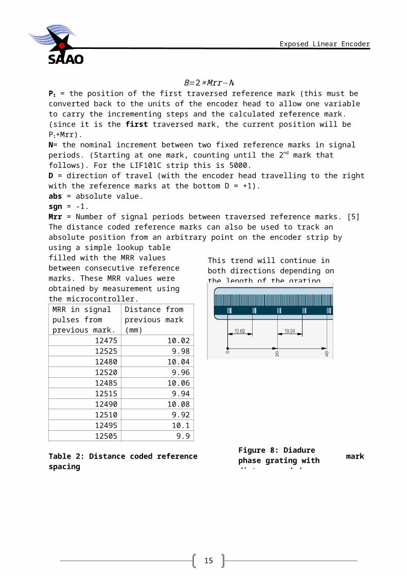
The following applies to heidenhain linear encoders with distance coded reference marks. Refer to figure 8 for layout of the marks.Before beginning the absolute reference calculation the values must be converted from the units of the encoder head to the units of the grating on the strip. The encoder head performs 5 fold evaluation on the signal, transforming an 4µm signal period into a 0.8µm signal period. Divide the output of the encoder head by 5 (0.8 = 4/5).The formula:
P1=(|(B )|−sgn B−1 )× N2
+(sgnB−sgnD)× Mrr2
B=2×Mrr−NP1 = the position of the first traversed reference mark (this must be converted back to the units of the encoder head to allow one variable to carry the incrementing steps and the calculated reference mark. (since it is the first traversed mark, the current position will be P1+Mrr).N= the nominal increment between two fixed reference marks in signal periods. (Starting at one mark, counting until the 2nd mark that follows). For the LIF101C strip this is 5000.D = direction of travel (with the encoder head travelling to the right with the reference marks at the bottom D = +1).abs = absolute value.sgn = -1.Mrr = Number of signal periods between traversed reference marks. [5]The distance coded reference marks can also be used to track an absolute position from an arbitrary point on the encoder strip by using a simple lookup table filled with the MRR values between consecutive reference marks. These MRR values were obtained by measurement using the microcontroller.
MRR in signal pulses from previous mark.
Distance from previous mark (mm)
12475 10.0212525 9.9812480 10.0412520 9.9612485 10.0612515 9.9412490 10.0812510 9.9212495 10.112505 9.9
Table 2: Distance coded reference mark spacing
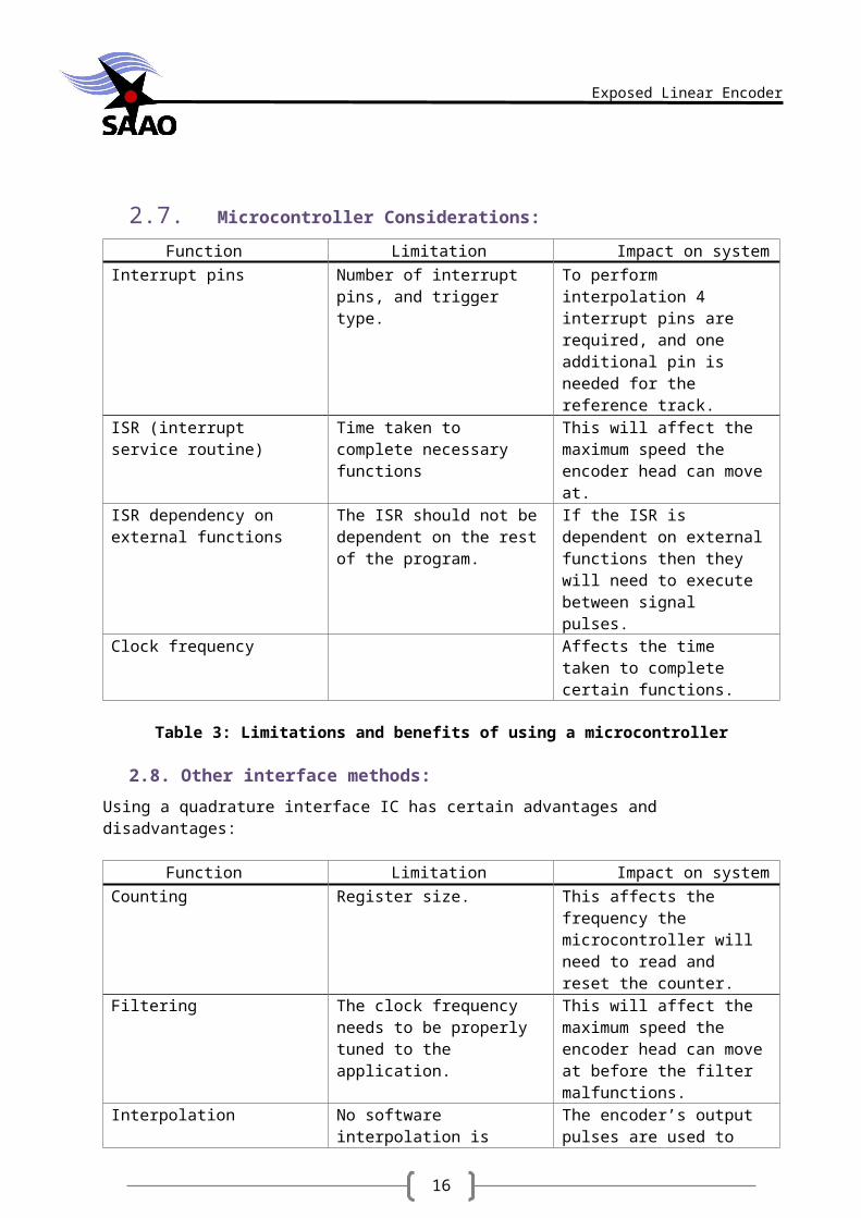
2.7. Microcontroller Considerations:
Function Limitation Impact on system
This trend will continue in both directions depending on the length of the grating strip.
Figure 8: Diadure phase grating with distance coded reference marks
14
Exposed Linear Encoder
Interrupt pins Number of interrupt pins, and trigger type.
To perform interpolation 4 interrupt pins are required, and one additional pin is needed for the reference track.
ISR (interrupt service routine) Time taken to complete necessary functions
This will affect the maximum speed the encoder head can move at.
ISR dependency on external functions
The ISR should not be dependent on the rest of the program.
If the ISR is dependent on external functions then they will need to execute between signal pulses.
Clock frequency Affects the time taken to complete certain functions.
Table 3: Limitations and benefits of using a microcontroller
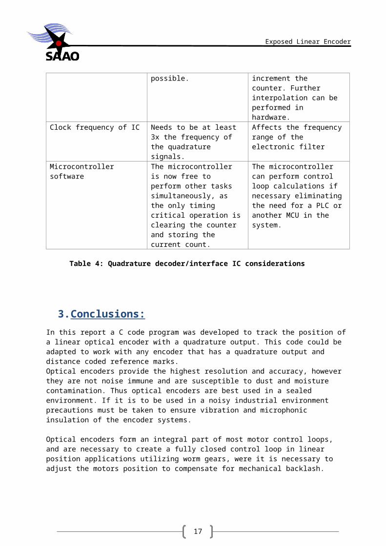
2.8. Other interface methods:
Using a quadrature interface IC has certain advantages and disadvantages:
Function Limitation Impact on systemCounting Register size. This affects the frequency the
microcontroller will need to read and reset the counter.
Filtering The clock frequency needs to be properly tuned to the application.
This will affect the maximum speed the encoder head can move at before the filter malfunctions.
Interpolation No software interpolation is possible.
The encoder’s output pulses are used to increment the counter. Further interpolation can be performed in hardware.
Clock frequency of IC Needs to be at least 3x the frequency of the quadrature signals.
Affects the frequency range of the electronic filter
Microcontroller software The microcontroller is now free to perform other tasks simultaneously, as the only timing critical operation is clearing the counter and storing the current count.
The microcontroller can perform control loop calculations if necessary eliminating the need for a PLC or another MCU in the system.
Table 4: Quadrature decoder/interface IC considerations
15
Exposed Linear Encoder
3.Conclusions:
In this report a C code program was developed to track the position of a linear optical encoder with a quadrature output. This code could be adapted to work with any encoder that has a quadrature output and distance coded reference marks.Optical encoders provide the highest resolution and accuracy, however they are not noise immune and are susceptible to dust and moisture contamination. Thus optical encoders are best used in a sealed environment. If it is to be used in a noisy industrial environment precautions must be taken to ensure vibration and microphonic insulation of the encoder systems.
Optical encoders form an integral part of most motor control loops, and are necessary to create a fully closed control loop in linear position applications utilizing worm gears, were it is necessary to adjust the motors position to compensate for mechanical backlash.
4.Recommendations:
In order to track the signal with more precision and perform additional interpolation it will be beneficial to utilize an external IC such as the HCTL20XX line, which is a quadrature decoder/interface IC. The HCTL20XX series is designed to utilize quadrature signals, and filter vibration induced noise, thus significantly increasing accuracy and drift.
Alternatively an MCU such as Atmega2560 with six interrupts. With 5 or more interrupt pins it would be possible to track 2 rising and falling edges per signal to track (Quadrature signal A and B + one interrupt for the reference track). However with so many ISR’s jockeying for control there is likely to be timing issues. By overclocking the MCU however it may be possible to perform mathematical filtering with higher adaptability than the electronic filter found in the HCTL20XX IC’s.It is usually necessary to filter optical encoder outputs, however many encoders include embedded electronics which simply supplies the 20 bit SSI value directly upon request. It is usually wise to take vibration damping precautions.
16
Exposed Linear Encoder
5.Appendices:
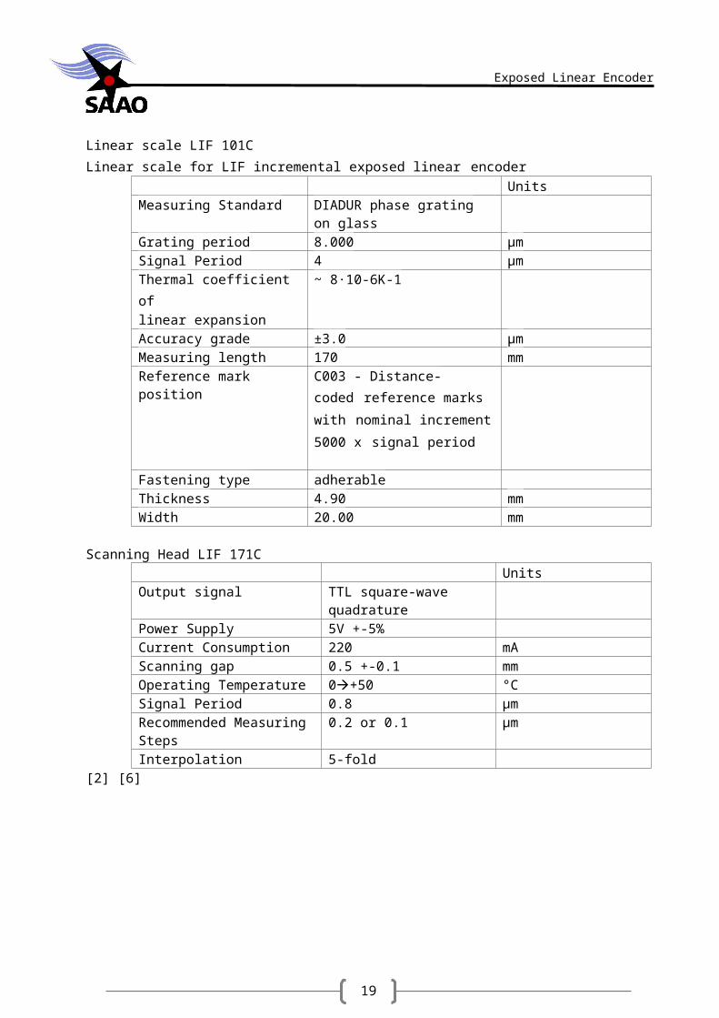
A.Data obtained from Heidenhain internal database:(by email).Linear scale LIF 101CLinear scale for LIF incremental exposed linear encoder
UnitsMeasuring Standard DIADUR phase grating on
glassGrating period 8.000 µmSignal Period 4 µm
Thermal coefficient of linear expansion
~ 8·10-6K-1
Accuracy grade ±3.0 µmMeasuring length 170 mmReference mark position C003 - Distance-
coded reference marks
with nominal increment 5000
x signal period
Fastening type adherableThickness 4.90 mmWidth 20.00 mm
Scanning Head LIF 171CUnits
Output signal TTL square-wave quadrature
Power Supply 5V +-5%Current Consumption 220 mAScanning gap 0.5 +-0.1 mmOperating Temperature 0+50 °CSignal Period 0.8 µmRecommended Measuring Steps
0.2 or 0.1 µm
Interpolation 5-fold[2] [6]
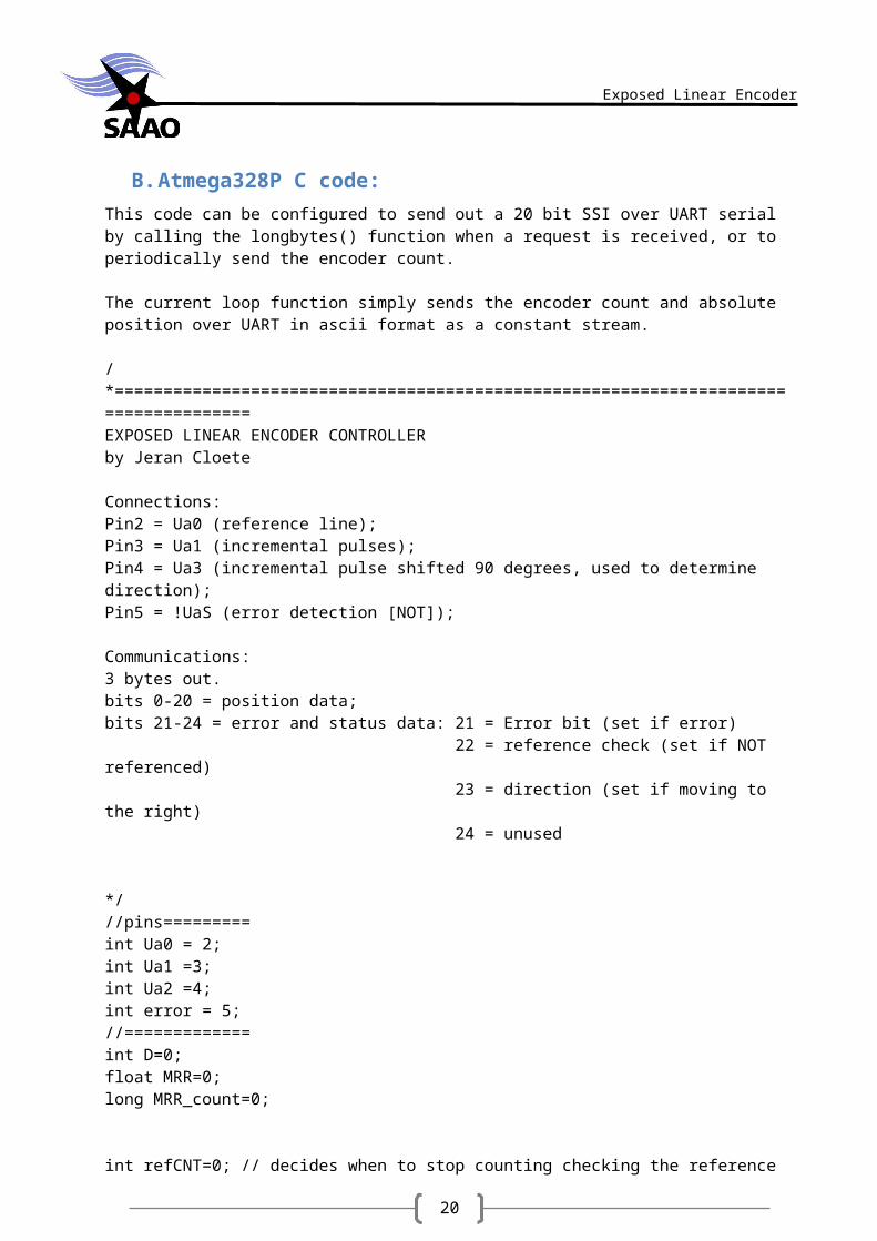
B.Atmega328P C code:This code can be configured to send out a 20 bit SSI over UART serial by calling the longbytes() function when a request is received, or to periodically send the encoder count.
17
Exposed Linear Encoder
The current loop function simply sends the encoder count and absolute position over UART in ascii format as a constant stream.
/*====================================================================================EXPOSED LINEAR ENCODER CONTROLLERby Jeran Cloete
Connections:Pin2 = Ua0 (reference line);Pin3 = Ua1 (incremental pulses);Pin4 = Ua3 (incremental pulse shifted 90 degrees, used to determine direction);Pin5 = !UaS (error detection [NOT]);
Communications:3 bytes out.bits 0-20 = position data;bits 21-24 = error and status data: 21 = Error bit (set if error) 22 = reference check (set if NOT referenced) 23 = direction (set if moving to the right) 24 = unused
*///pins=========int Ua0 = 2;int Ua1 =3;int Ua2 =4;int error = 5;//=============int D=0;float MRR=0;long MRR_count=0;
int refCNT=0; // decides when to stop counting checking the referenceint ref;
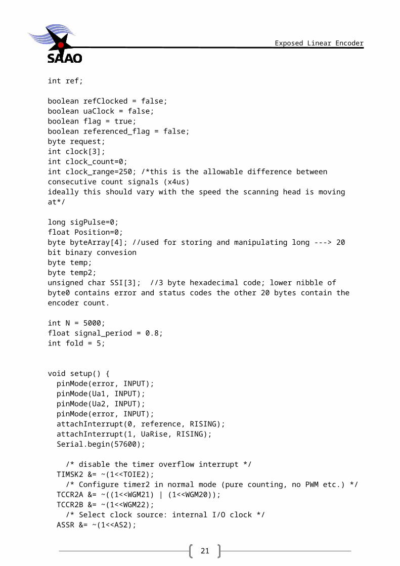
boolean refClocked = false;boolean uaClock = false;boolean flag = true;boolean referenced_flag = false;byte request;int clock[3];int clock_count=0;int clock_range=250; /*this is the allowable difference between consecutive count signals (x4us)ideally this should vary with the speed the scanning head is moving at*/
long sigPulse=0;float Position=0;byte byteArray[4]; //used for storing and manipulating long ---> 20 bit binary convesionbyte temp;byte temp2;
18
Exposed Linear Encoder
unsigned char SSI[3]; //3 byte hexadecimal code; lower nibble of byte0 contains error and status codes the other 20 bytes contain the encoder count.
int N = 5000;float signal_period = 0.8;int fold = 5;
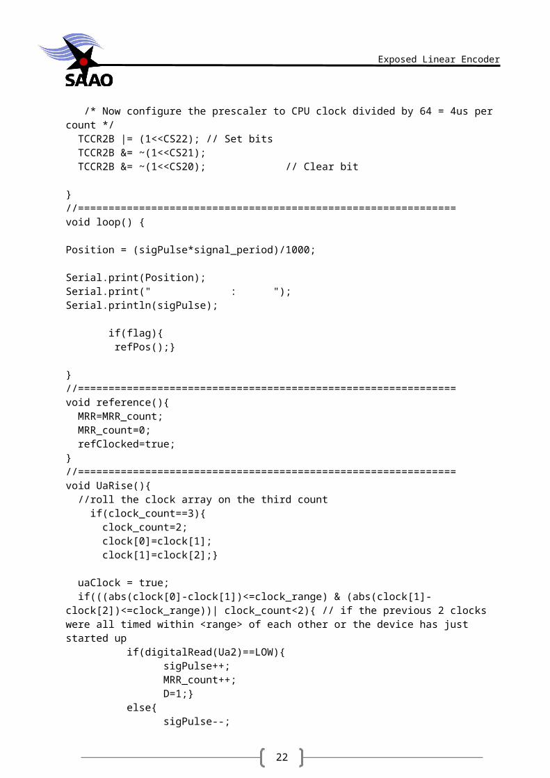
void setup() { pinMode(error, INPUT); pinMode(Ua1, INPUT); pinMode(Ua2, INPUT); pinMode(error, INPUT); attachInterrupt(0, reference, RISING); attachInterrupt(1, UaRise, RISING); Serial.begin(57600); /* disable the timer overflow interrupt */ TIMSK2 &= ~(1<<TOIE2); /* Configure timer2 in normal mode (pure counting, no PWM etc.) */ TCCR2A &= ~((1<<WGM21) | (1<<WGM20)); TCCR2B &= ~(1<<WGM22); /* Select clock source: internal I/O clock */ ASSR &= ~(1<<AS2); /* Now configure the prescaler to CPU clock divided by 64 = 4us per count */ TCCR2B |= (1<<CS22); // Set bits TCCR2B &= ~(1<<CS21); TCCR2B &= ~(1<<CS20); // Clear bit
}//==============================================================void loop() {
Position = (sigPulse*signal_period)/1000;
Serial.print(Position);Serial.print(" : ");Serial.println(sigPulse);
if(flag){ refPos();} }//==============================================================void reference(){ MRR=MRR_count; MRR_count=0; refClocked=true; }//==============================================================void UaRise(){ //roll the clock array on the third count if(clock_count==3){ clock_count=2;
19
Exposed Linear Encoder
clock[0]=clock[1]; clock[1]=clock[2];}
uaClock = true; if(((abs(clock[0]-clock[1])<=clock_range) & (abs(clock[1]-clock[2])<=clock_range))| clock_count<2){ // if the previous 2 clocks were all timed within <range> of each other or the device has just started up if(digitalRead(Ua2)==LOW){ sigPulse++; MRR_count++; D=1;} else{ sigPulse--; MRR_count--; D=-1;} //============timing the pulses to eliminate vibration induced noise clock[clock_count] = TCNT2; TCNT2 = 0; clock_count++; } }//==============================================================void refPos(){ float P1; float B; float sgnB = -B; float sgnD = -D; if(refCNT<2){ if(refClocked==true){ //Serial.println("================================================================"); refClocked=false; refCNT++; if(refCNT==2){ refCNT=0; //===============corrects a miscount if a trigger was missed /*int x = MRR%5; if(x>0){ MRR=MRR+x;}*/ //=================================== MRR=MRR/fold; //converts between the strips 4um grid and the encoders 0.8um step B=2*abs(MRR)-N; P1=(abs(B)-sgnB-1)*(N/2)+(sgnB-sgnD)*(abs(MRR)/2); if(D==-1){ sigPulse = (P1+abs(MRR))*fold;} // add MRR because P1 is the location of the FIRST traversed reference mark else{
20
Exposed Linear Encoder
sigPulse = (P1-abs(MRR))*fold;} // add MRR because P1 is the location of the FIRST traversed reference mark flag = false; referenced_flag = true; /* Serial.print(" MRR = "); Serial.println(MRR); Serial.println("================================================================"); delay(5000);*/ } } } }//=====================================================================================================//This function converts the encoder count to a 20 bit number to match the industry standard 20 bit SSI output found on most encoders//=====================================================================================================void longBytes(){ // convert from an unsigned long int to a 4-byte array byteArray[3] = (int)((sigPulse >> 24) & 0xFF) ; byteArray[2] = (int)((sigPulse >> 16) & 0xFF) ; byteArray[1] = (int)((sigPulse >> 8) & 0XFF); byteArray[0] = (int)((sigPulse & 0XFF)); //========================20 bit format================================== byteArray[2] = byteArray[2] << 4; temp = byteArray[1]>>4; byteArray[2] = byteArray[2]|temp; //byte 2 now contains [byte2 lower nibble][byte1 upper nibble] temp = byteArray[1]<<4; //temp now has byte1 lower nibble in upper nibble slot temp2 = byteArray[0]>>4;//temp 2 has byte0 upper nibble in lower nibble slot byteArray[1] = temp|temp2; byteArray[0] = byteArray[0]<<4; //======================================================================= SSI[2] = byteArray[2]; SSI[1] = byteArray[1]; SSI[0] = byteArray[0]; //set the error bit if the error line is LOW (there is an error) temp = digitalRead(error); if(temp==0){ bitSet(SSI[0], 3);} else{ bitClear(SSI[0], 3);} // SET the reference bit if the encoder has NOT performed the reference run. if(referenced_flag){ bitClear(SSI[0], 2);}
21
Exposed Linear Encoder
else{ bitSet(SSI[0], 2);} //set the direction bit if the encoder has most recently moved to the right bitWrite(SSI[0], 1, D); Serial.write(SSI[2]); Serial.write(SSI[1]); Serial.write(SSI[0]); }//=======================================================================================================
C.Heidenhain linear optical encoder brochure
D.HCTL2032 Quadrature decoder/interface IC.
References
22
Exposed Linear Encoder
[1] Various, "wikipedia," [Online]. Available: http://en.wikipedia.org/wiki/Position_sensor.[2] Heidenhain, 2013. [3] J. Miller, "Quantum Devices INC," 10 February 2010. [Online]. Available:
http://quantumdevices.wordpress.com/2010/02/22/why-use-an-optical-quadrature-encoder-for-a-motor-encoder/. [Accessed 2013].
[4] Avago Technologies, "Quadrature decoder/interface IC's," 2007.[5] DR. Johannes Heidenhain GmbH, "Heidenhain," 2007. [Online]. Available:
www.heidenhain.com.[6] "A Tech Authority," [Online]. Available: www.atechauthority.com. [Accessed 09 2013].[7] D. S. Nyce, "Linear Position sensors Theory and application," John Wiley and Sons Inc.,
Hoboken, New jersey, 2004.[8] S. Y. Xi Chen, "Optical Inertial Vibration sensor system using grating technology," SPIE
digital library, 2013.