exploration | drilling | production march 2019 · when faced with a critical well event, you need...
TRANSCRIPT

MARCH 2019 EXPLORATION | DRILLING | PRODUCTION

© 2019 National Oilwell Varco | All Rights Reserved © 2019 National Oilwell Varco | All Rights Reserved
No matter the shale play, we have the equipment you need to tackle your intervention challenges.
Learn more about how our intervention and stimulation equipment helps you handle
multi-well and extended-reach operations at nov.com/intervention.
From the Permian
to the Bakken

Copyright © Palladian Publications Ltd 2019. All rights reserved. No part of this publication may be reproduced, stored in a retrieval system, or transmitted in any form or by any means, electronic, mechanical, photocopying, recording or otherwise, without the prior permission of the copyright owner. All views expressed in this journal are those of the respective contributors and are not necessarily the opinions of the publisher, neither do the publishers endorse any of the claims made in the articles or the advertisements. Printed in the UK.
Oilfi eld Technology is audited by the Audit Bureau of Circulations (ABC). An audit certifi cate is
available on request from our sales department.
MARCH 2019 EXPLORATION | DRILLING | PRODUCTION
ISSN 1757-2134
CCoontentsntentsMarch 2019 Volume 12 Issue 03
More from Read on the goApp available on Apple/Android
Like us on FacebookOilfield Technology
Join us on LinkedInOilfield Technology
Follow us on Twitter@OilfieldTechMag
2247
Front cover
Abaco Drilling Technologies is
a leading technology-driven
manufacturer of power sections
for oil and gas drilling and
thru-tubing operations.
Our modern facilities, precision
manufacturing capabilities,
quality control, R&D, and
engineering proficiency deliver
ideal elastomer and power
section solutions that increase
efficiency, improve safety
and maximise downhole
performance.
03 Comment
05 World news
10 Weighing the oddsOilfield Technology Correspondent, Gordon Cope, reviews the state of
the upstream industry in the Middle East and Northern Africa.
13 Leveraging legacy dataJo Firth and Priyabrata Pradhan, CGG, UK, explore the value in
reprocessing legacy seismic data sets.
18 A critical componentTom Hewitt, Jordan Lewis, and Stephen Forrester, NOV, examine the use
of custom solutions to the challenges of North American coiled tubing.
23 Enhancing tubing technologyIrma Galvan, Global Tubing, USA, explores how the rise of ‘super lateral’
wells is driving the optimisation of coiled tubing interventions.
27 Collaborative completionsDale Logan, C&J Energy Services and Panos Adamopoulos, Seismos, USA,
examine a combination of new technologies designed to optimise horizontal
completions.
30 Developing a digital futureManoj Nimbalkar, Weatherford International, USA, discusses recent advances
in digital and cloud-based technology designed to drive oilfield productivity.
33 Thinking outside the boxAndrew Poerschke, Teddy Mohle and Paul Ryza, Apergy, discuss a new
approach to implementing artificial gas lift designed to improve production
in declining wells.
37 Keeping things crystal clearSimon Larson, Siemens, Sheng Kun Sun, CNPC, and Xiao Ming Sun,
Liaohe Petro Engineering Company, review water treatment measures
designed to comply with China’s tough new treatment standards.
41 Well Control Q&AOilfield Technology invited experts from Cudd Well Control, Halliburton,
RESMAN and Wild Well Control to share their knowledge on a variety of well
control topics.
46 An integrated approachMichael MacMillan, C-Innovation, USA, discusses the benefits that a
single-source ROV and vessel support services solution can deliver for subsea
construction projects.

When faced with a critical well event, you need to rely on the experienced well control leaders to resolve your situation quickly and safely. Cudd Well Control promptly responds to assess the situation and develop a plan of action to return your operations to production.
• Well Firefighting/Blowout Operations
• Well Control Engineering
• Surface and Subsea Well Control
• Well Recovery Operations
• Hot Tap Operations
• Gate Valve Drilling
• Freeze Operations
+1.713.849.2769 | cuddwellcontrol.com
CRITICAL WELL INTERVENTION SERVICES

Comment March 2019
David Bizley, Editordavid.bizley@oilfi eldtechnology.com
March 2019 Oilfield Technology | 3
Contact us Contact us
Subscription Subscription
EditorialManaging Editor: James Little
Editor: David Bizley
Editorial Assistant: Aimee Knight
DesignProduction: Hayley Hamilton-Stewart
SalesAdvertisement Director: Rod Hardy
Advertisement Manager: Ben Macleod
WebsiteWebsite Manager: Tom Fullerton
Digital Editorial Assistant: Nicholas Woodroof
MarketingSubscriptions: Laura White
Reprints: [email protected]
Palladian Publications Ltd,
15 South Street, Farnham, Surrey GU9 7QU, UK
Tel: +44 (0) 1252 718 999 Fax: +44 (0) 1252 718 992
Website: www.oilfieldtechnology.com
Oilfield Technology subscription rates: Annual subscription
£80 UK including postage/£95 overseas (postage airmail). Two
year discounted rate £128 UK including postage/£152 overseas
(postage airmail).
Subscription claims: Claims for non receipt of issues must be
made within three months of publication of the issue or they will
not be honoured without charge.
Applicable only to USA & Canada: OILFIELD TECHNOLOGY
(ISSN No: 1757-2134, USPS No: 025-171) is published monthly
by Palladian Publications, GBR and is distributed in the USA
by Asendia USA, 17B S Middlesex Ave, Monroe NJ 08831.
Periodicals postage paid New Brunswick, NJ and additional
mailing off ices.
Postmaster: Send address changes to Oilfield Technology, 701C
Ashland Ave, Folcroft PA 19032.
A fter a gloomy start to 2019 and the January slump that saw
oil prices fall to the low-US$50s, Brent crude is back on the
rise again – at least for now.
The return of Brent crude to the mid-US$60s range has
largely been driven by OPEC’s continued output cuts. OPEC and
its allies have actually over-delivered on the cuts with a further
300 000 bpd decline. According to a Reuters survey, the 11 OPEC members bound by the
deal managed to achieve 101% compliance with the agreed-upon cuts, up from 70% in
January. Saudi Arabia alone produced 130 000 bpd less than in January, whilst Kuwait,
the UAE and Iraq also all made significant cuts.1
Adding an interesting geopolitical twist to the proceedings is the fact that these
increased cuts have occurred despite US President Donald Trump urging OPEC and its
allies to produce more and reduce efforts to raise prices. When questioned by Reuters,
sources at OPEC simply said: “We are sticking to the plan.”2
Involuntary cuts also played a part in the production decline. Venezuela’s already
ailing output was hit by newly imposed US sanctions on PDVSA. Once a leading global
supplier, and despite being blessed with vast natural reserves, Venezuela’s output has
fallen significantly as a result of years of mismanagement. Iran also continues to be the
subject of US sanctions, which have seen its output fall. Some estimates show that the
sanctions on these two countries have taken as much as 2 million bpd of supply off the
global market.
Analysts are treating the news of tightening supply with some optimism – a
note released by Barclays was quick to point out that: “OPEC exports are off by over
1.5 million bpd since November”, and a spokesperson for Fitch Solutions was quoted as
saying that they expected Brent crude to average US$73/bbl this year.3
Another factor driving up prices is the news that the US and China could be close to
signing a trade deal that would end the ongoing tariff row between the two economic
giants. The disagreement, which had seen heavy tariffs placed on hundreds of goods
including solar panels, washing machines, aluminium, airplanes, cars, pork, and
soybeans, had been acting as something of a wet blanket on the global economy. The
news that this dispute could soon be over has boosted hopes that economic activity will
increase and drive further oil demand. Given the current rate of progress, a formal trade
deal could be agreed upon by President Trump and President Xi by the end of March.4
All things considered, the signs are looking fairly positive for the upstream sector
– challenges still remain, but the silver linings currently outnumber the clouds. As we
head into spring, here’s hoping that the signs of new life continue to grow and eventually
bloom.
References1. ‘In rebuff to Trump, OPEC oil output drops further in February’ – https://uk.reuters.com/article/
uk-oil-opec-survey/opec-oil-output-drops-further-in-february-as-saudi-over-delivers-on-cuts-idUKKCN1QI4GT?rpc=401&
2. Ibid.3. ‘Oil climbs on US-China trade deal hopes, OPEC’s deepening supply cuts’ – https://www.cnbc.
com/2019/03/04/oil-markets-us-china-trade-opec-in-focus.html 4. Ibid.

TERMINATORSACRIFICIAL DEPLOYMENT MOTOR
Visit www.downholeproducts.com to fi nd out more
Final string deployment
Disposable motor
Fully confi gurable
Value added solution

World newsMarch 2019
In brief In brief
March 2019 Oilfield Technology | 5
Tendeka secures multi-million-pound AICD contract to boost oil recovery in Middle EastIndependent global completions service company Tendeka has secured a further
multi-million-pound contract with a major national oil company in the Middle East.
The agreement will see Tendeka provide reservoir modelling and the installation of its
FloSure Autonomous Inflow Control Devices (AICDs) to boost production and improve reservoir
performance in several mature fields. The company will perform reservoir simulations for
each well, working closely with the client to ensure optimum reservoir performance, with the
technology helping in the reduction of unwanted fluid production.
Having carried out several similar projects in the region, the company has significant
experience of the challenges of brownfields and carbonate reservoir that form a large proportion
of oilfields in the Middle East.
Scott Watters, Chief Operating Officer at Tendeka, said: “This is a major contract for the
business and one that continues a long and well-established relationship with the client. We’re
renowned for our FloSure technology with a strong track record in supporting clients and driving
efficiencies.
“Our FloSure technology and global supply chain capability has allowed us to bring real
value to major Middle East projects. We are committed to the continuous development of this
technology to tackle future challenges and smooth field development planning for the long term.
It’s an area we aim to grow over the coming months and years.”
Shearwater GeoServices awarded 4D contractsShearwater GeoServices Holding AS has
announced the award of three 4D seismic
surveys by Equinor AS to be conducted this
summer. The projects confirm Shearwater’s
Isometrix crews will be active in 2019, on 4D
projects in the North Sea and Barents Sea.
Equinor has awarded Shearwater a
multi-project contract, with three surveys
to be conducted in 2019 at the Kvitebjørn
& Valemon, Visund and Snøhvit fields.
The first survey is scheduled to start in
Q2 and the total duration for the three
2019 projects is estimated at around 3
months. The surveys will be conducted
by Shearwater’s Amazon Conqueror and
SW Amundsen.
“We see a clear increase in activity in
the 4D market in 2019, and we are very
pleased to see a leading purchaser of 4D
seismic choosing Shearwater’s Isometrix
technology for their 4D surveys. Shearwater
has decades of innovation and crew
experience in 4D and it is important to
see this capability selected by established
clients,” said Irene Waage Basili, CEO of
Shearwater GeoServices.
Block Energy to acquire 100% interest in West Rustavi fieldBlock Energy Plc, the exploration and production
company focused on the Republic of Georgia,
has announced that it has secured an agreement
with Georgian Oil and Gas Limited to increase its
working interest in the West Rustavi licence to
100% from the current 25%.
Block’s interest in the Licence is held via its
100% owned subsidiary Georgia New Ventures,
Inc which is also party to the Agreement. The
Agreement replaces the original earn-in deal,
which provided that Block would increase its
WI to 75% upon completion of the Company’s
ongoing West Rustavi workover and sidetracking
programme.
On completion of the transaction Block
will take full strategic control of future
operations in the field, which holds an
estimated 38 million bbls of gross contingent
resources (‘2C’) of oil (source: CPR completed
by Gustavson Associates, 1 January 2018), and a
legacy gas discovery.
According to the well passport the company
received on acquiring its interest in the 36.5 km2
Licence, one of West Rustavi’s discovery
wells flowed at rates up to 29 000 m3/d when
originally tested in 1988.
Senegal MODEC, Inc. has announced that its
subsidiary, MODEC International Inc.,
has been awarded a contract by
Woodside Energy (Senegal) B.V., as
Operator of the SNE Field Development,
for a floating production storage and
offloading (FPSO) vessel for Senegalese
waters.
Under the contract, MODEC will
perform Front-End Engineering Design
(FEED) for the FPSO and, subject to a
final investment decision on the project
in 2019, will be responsible for the
supply, charter and operations of the
FPSO.
The SNE deepwater oilfield is
expected to be Senegal’s first offshore
oil development. The field is located
within the Sangomar Deep Offshore
permit area, approximately 100 km
south of Dakar, Senegal.
Algeria Neptune Energy and Sonatrach
have announced that first gas
has gone in to the Touat project
in Algeria as part of project
commissioning. The development,
which will produce around 75 000 boe/d
(450 million standard ft3/d) at plateau,
remains on track to commence gas
export production by the end of the
first half of 2019.
Touat comprises eight gas fields
and a gas processing plant and is
located in the Basin of Sbaa, 1500 km
southwest of Algiers, near Adrar.
Jim House, Neptune CEO,
said: “First gas in at Touat marks
a significant milestone for this
important project. We are now focused
on delivering commercial full export
production by the end of the first half
of the year.”

World newsMarch 2019
Diary dates Diary Diary dates
To read more about these articles and for more event listings go to:
Web news Web news highlightshighlights
www.oilfieldtechnology.com
6 | Oilfield Technology March 2019
Andalas Energy & Power announce Colter well update
EnerQuip sets sail on Vantage drillship project
N-Sea announces multi-million pound North Sea contract wins
Weatherford completes sale of Algeria land drilling rigs
Lundin Petroleum completes exploration wellLundin Petroleum AB (Lundin Petroleum)
has announced that its wholly
owned subsidiary Lundin Norway AS
(Lundin Norway) has completed the
drilling of exploration well 7121/1-2 S,
targeting the Pointer and Setter prospects
in PL767 in the southern Barents Sea.
Oil shows were encountered at various
intervals in the Pointer prospect but the
well is classified as dry.
The main objective of the well, located
20 km north of the Snøhvit gas field, was
to test the two distinct lower Cretaceous
sandstone targets, the shallower Setter
prospect and the deeper Pointer prospect.
Water wet sands with a total
thickness of 40 m with moderate reservoir
properties were encountered in the
Setter prospect. In the Pointer prospect,
about 130 m of sand with oil shows
was found, however the reservoir was
evaluated to be tight and of low quality
across the entire interval. The well was
not formation-tested, but extensive
data acquisition and sampling have
been carried out. The well has been
permanently plugged and abandoned.
KCA Deutag awarded US$110 million of land drilling contracts in the Middle East, Russia and AfricaKCA Deutag has announced that its land drilling operation has won new contracts and
contract extensions worth approximately US$110 million.
In the Middle East, KCAD has been successful in winning a total of 7 years of contract
extensions for five heavy rigs operating in Oman. The extension for each rig ranges from
one to two years. In addition to this, the company has also signed a contract with a new
client in Oman for one of its 2000hp rigs.
In Russia, the company has been awarded a contract for a 1000 hp rig with one of
the country’s leading integrated oil companies. KCAD is also the drilling contractor on
three platforms offshore Sakhalin Island.
In Nigeria one of the company’s 700 hp rigs has won a one year contract to carry out
a workover programme, with a further one year extension option. Additionally a second
rig has won a short term contract for a three month programme.
This 1500 hp rig will be operating in an area of Nigeria where KCA sees increasing
activity. This is the rig’s second contract in quick succession in this location and there
are many other active opportunities that are currently being pursued.
KCAD has also had some success in Algeria, where it was awarded a short term
contract extension for one of its 1500 hp Speed rigs.
18 - 21 March, 2019
MEOS 2019Manama, BahrainE: [email protected]
27 - 29 March, 2019
OMC 2019Ravenna, ItalyE: [email protected]
06 - 09 May, 2019
OTCHouston, USAE: [email protected]
19 - 22 May, 2019
AAPG ACESan Antonio, USAE: [email protected]/2019
22 - 24 July, 2019
URTeC 2019Denver, USAE: [email protected]
www.urtec.org
Aker Solutions to develop digital twin for Nova fieldAker Solutions has been appointed by
Wintershall AS to build a complete digital
replica of the Nova production system to
enable data driven engineering, production and
maintenance decisions.
Through two separate agreements,
Aker Solutions will provide both a fully
interactive digital replica of the integrated
production system as well as undertake a study
to enable live data streaming and condition
monitoring of the subsea equipment.
The digital twin will become an advanced
replacement to traditional paper-based
handbooks and equipment documentation,
ensuring that all relevant engineering data
is held centrally in a single, interactive
and searchable solution. It will be built
on a cloud-based architecture capable of
processing live data and ensuring that vital
engineering information is kept up to date at
all times.
The connected study to enable live
data streaming from the subsea production
equipment will be instrumental in driving
forward real time subsea condition monitoring,
production optimisation and predictive
maintenance for the field.

03/19 © TETRA Technologies, Inc. All Rights Reserved.
Delivering More Through LessBy “Closing the Loop on Water Management”
Automation and Monitoring • Sourcing • Fresh and Produced Water Transfer •Pipeline Construction • Storage and Pit Lining •Treatment and Recycling •Oil Recovery • Blending and Distribution • Flowback and Testing
Close the loop and clear the way for a new approach to managing water in shale plays. Our fully automated and integrated water management solution helps meet your increasing water requirements by treating, recycling, and optimizing produced water for fracturing operations – all while yielding
provide you with the lowest cost per barrel water management solution.
TETRA Integrated Water Management Solution
TETRA Automated Technology

8 | Oilfield Technology March 2019
March 2019World news
RockRose Energy plc to acquire Marathon Oil UKRockRose has announced that it has signed a share
purchase agreement (‘SPA’) to acquire 100% of
Marathon Oil U.K. LLC and 100% of Marathon Oil West
of Shetland Limited from subsidiaries of Marathon
Oil Corporation. The consideration payable by
RockRose to Marathon Oil in connection with
the Acquisition is circa US$140 million (subject to
customary adjustments), which RockRose currently
anticipates will be funded through existing resources
and facilities.
MOUK holds 37 - 40% operated interests in fields
in the Greater Brae Area and MOWOS holds a 28%
interest in the BP plc operated Foinaven Field unit
and a 47% interest in Foinaven East, respectively.
RockRose Executive Chairman, Andrew Austin
said: “This acquisition marks a major step change in
the Group’s reserves and production profile. Given
the quality of these assets the Board’s view is this is
a good opportunity to make the transition to the role
of operator.
We look forward to welcoming Marathon Oil UK
employees, who have an excellent track record
operating in the North Sea, to the RockRose team at
closing.”
McDermott awarded EPCI contract from Saudi AramcoMcDermott International, Inc. has announced
a large contract award from Saudi Aramco for
engineering, procurement, construction and
installation (EPCI) services in the Marjan field,
offshore Saudi Arabia.
The contract includes the full suite of
EPCI services for the upgrade of two existing
platforms related to the installation of associated
equipment for electrical submersible pumps
(ESPs) and space for a future high integrity
pressure protection system (HIPPS), subsea
composite cable lay and topside cable tie-ins.
“This award is testament to Saudi Aramco’s
confidence in McDermott’s ability to execute
this complex type of project,” said Linh Austin,
McDermott’s Senior Vice President, Middle East
and North Africa. “We have a long track record of
executing similar scopes of work and believe that
by working closely with our clients we can offer
industry leading solutions which are suited to this
evolving market segment.”
Santos boosts operated position across off shore Northern AustraliaSantos has announced that it has reached an agreement to align the company’s
interests, under Santos operatorship, across four exploration permits in the
Bonaparte Basin offshore Northern Australia adjacent to a large existing contingent
resource.
Santos’ position in the Bonaparte Basin already includes an 11.5% interest in
the Bayu-Undan gas-condensate field and the Darwin LNG plant, as well as a 25%
interest in the Barossa field, which is currently in front end engineering and design
and is the leading candidate to backfill Darwin LNG.
The transaction with Beach Energy will see the companies become 50/50 joint
venture partners across NT/P82, NT/P85, NT/P84 and WA-454-P. Santos will operate
all four permits.
Permits NT/P82 and NT/P85 are located immediately to the south of the Barossa
project area, where Santos acquired the 4347 km2 Bethany 3D seismic survey in
2018. NT/P84 and WA-454-P are proximal to the Petrel/Tern/Frigate field complex in
the Petrel sub-basin, where separate agreements with Neptune Energy see Santos
move to 100% operated interest in the Tern and Frigate fields and a 40.25% interest
in the Petrel field, subject to customary approvals.
Santos Managing Director and Chief Executive Officer Mr Kevin Gallagher said:
“This alignment of equity and operatorship will allow for a more strategic approach
to the next phase of exploration in the region.”
“The next step for these permits is to evaluate new and existing seismic data to
build inventory and define potential targets for drilling within the next few years.
Permits NT/P82 and NT/P85, which are located immediately south of our Barossa
project, will be a key focus for this work,” Mr Gallagher said.
Wood awarded EPCI contract by Equinor in Norway Wood has secured a new US$13 million contract with Equinor to deliver engineering,
procurement, construction, and installation (EPCI) services to the Vigdis boosting station
increased oil recovery (IOR) project.
Effective immediately, Wood will provide topside modifications to enable the tie-in
of subsea equipment to offshore platforms Snorre A and Snorre B, which process oil from
the Vigdis subsea field, located in the Norwegian North Sea.
The contract is delivered from Wood’s office in Sandefjord, Norway, and follows
the company’s successful completion of the front-end engineering design (FEED) and
concept study for the asset. Wood also currently provides maintenance, modification
and operations (MMO) services on Snorre A and B under a framework agreement with
Equinor.
Dave Stewart, CEO of Wood’s Asset Solutions business in Europe, Africa, Asia &
Australia, comments: “Wood has a longstanding relationship with Equinor and this
contract award further demonstrates their confidence in our offshore modifications
capabilities. This new contract also supports our strategic focus on solidifying our
position as a modifications service provider in Norway.”
Lars Fredrik Bakke, Wood’s senior vice president in Norway adds: “Wood has decades
of experience in the Norwegian energy sector. This experience, combined with our local
engineering team’s customer specific knowledge of Equinor’s processes and systems,
positions us ideally to safely and successfully deliver this contract.”
On completion of the project, production from the Vigdis field will be increased by
almost 11 million bbls.

Clearly Better.
Marine Acquisition
Processing & Imaging
Reveal Software
Multi-Client
shearwatergeo.com

WEIGHING THE ODDS
Oilfield Technology Correspondent, Gordon Cope, reviews the state of the upstream industry in the Middle East and Northern Africa.
10 |

TThe countries of the Middle East and Northern Africa (MENA)
have an incredible profusion of hydrocarbons – and an
unenviable track record of war, misfortune and catastrophe.
The global oil and gas sector is also facing wrenching
transformations to which the MENA region is by no means immune.
The growth in North American production, the political travails of key
OPEC members and the comprehensive US sanctions against Iran all
threaten traditional markets.
Many MENA countries have the intelligence and foresight to take
the initiative and prepare for the future. Others are mired in social,
cultural and mismanagement complications that threaten their
prospects. The stakes are high: who will win the race? This article
considers the winners, placers, also-rans and long-shots.
WinnersThe smart money is on Qatar, which has almost 800 trillion ft 3 of gas
reserves and is the world’s largest producer of LNG. According to the
International Gas Union, Qatar exported 81 million t of LNG in 2017,
over one quarter of global trade.
Qatar announced that it will boost capacity by approximately
30% over the next five to seven years. The decision is predicated, in
part, by the tremendous increase in Chinese LNG demand as it tries
to ween domestic industry and utilities off coal. In September 2018,
Qatargas announced that it had signed a new, 22 year contract with
China to supply 3.4 million tpy.
On the diplomatic front, Qatar has been at loggerheads with
Saudi Arabia and neighbouring countries over its support of the
Muslim Brotherhood and the Al-Jazeera TV network. In December,
2018, Qatar announced that it would withdraw its membership from
OPEC, starting on January 1, 2019. Government off icials stated that
the country would focus on its long-term LNG growth strategy.
Saudi Arabia is also a front runner, with 261 billion bbls in
proven reserves and 10.5 million bpd of production (and exports of
7.6 million bpd). While Saudi Arabia suff ers from severe geopolitical
complications, its oil and gas sector has outlined a promising
future by diversifying the economy away from oil exports. In early
December 2018, Saudi Aramco announced that it would spend more
than US$100 billion over the next decade in petrochemicals in order
to balance its upstream and downstream holdings. The eventual
goal is to have 8 - 10 million bpd of integrated chemical, refining and
marketing capacity. The chemical portion, especially, is expected to
grow from one-third to nearly half. Much of the chemical component
is planned for high growth countries such as China and India.
Lost in all the news is the country’s move toward unconventional
resources. The World Energy Council estimated that Saudi Arabia’s
recoverable conventional gas reserves stood at approximately
280 trillion ft 3. There are no off icial estimates for the size of its
unconventional resources, although Aramco off icials have noted that
they are ‘huge’.
Saudi Aramco began developing unconventional gas in
the North Arabia field in early 2018, ramping up production to
190 million ft 3/d to meet the needs of Wa’ad Al Shamal, a mining and
industrial city in northern Saudi Arabia.
Saudi Aramco now has 16 unconventional rigs which completed
over 70 wells around the country in 2018. The programme is part of
the kingdom’s plan to spend US$150 billion to increase domestic
gas production from 14 billion ft 3/d to 23 billion ft 3/d within the next
decade. The increase is to meet growing domestic demand from
consumers and industry, as well as off set exportable liquids that are
currently consumed by utilities.
The smart punters are backing Abu Dhabi. In late 2018,
Abu Dhabi’s Supreme Petroleum Council green-lighted the spending
of US$132 billion over the next five years to expand oil and gas.
State-owned ADNOC announced that one of its first goals will
be to boost crude production to 4 million bpd by 2020. A major
component is the upgrading and expansion of its giant Bu Hasa
production complex. The onshore field will increase output from
550 000 bpd to 650 000 bpd through a combination of new pipelines
and production hubs, as well as a second gas-lift recovery phase.
ADNOC also announced plans to grant Italy’s Eni a 40-year
concession in its off shore Ghasha concession ultra-sour gas fields.
The concession is for a 25% stake in the project. ADNOC estimates
that the area holds several trillion ft 3 of recoverable gas, with the
potential to produce up to 1.5 billion ft 3/d.
Finally, the US Geological Survey (USGS) estimates that
Silurian, Jurassic and Cretaceous source rocks beneath the
United Arab Emirates hold over 200 trillion ft 3 of technically
recoverable natural gas and 22 billion bbls of technically recoverable
crude. ADNOC will target 1 billion ft 3/d of unconventional gas
production by 2030. The state-owned company recently contracted
Total to explore the onshore Ruwais Diyab unconventional gas
concession, which is considered to have similar potential to some
of the premier North American shale gas plays. The deal calls for up
to seven years of exploration and appraisal, followed by a 40 year
production phase.
Off shore exploration in Egypt’s Mediterranean waters is finally
paying off for the African nation. Within the last 12 months, gas
has begun to flow from several major gas fields, including the
30 trillion ft 3 Zorh field. As of September 2018, Egypt halted imports
of expensive LNG, which cost it over US$2.6 billion annually. It is now
seeking out deals with neighbouring countries. It has contracted with
Cyprus to build a pipeline to ship Cypriot gas to its LNG facility in
| 11

12 | Oilfield Technology March 2019
order to process the gas and re-export it to Europe. Earlier in the year,
Egypt signed an agreement with Israel to import gas from the latter’s
off shore gas fields.
Oman is having a strong run. The Middle East country
has 5 billion bbls of proven reserves and produces almost
1 million bpd, of which 80% is exported as crude. For over a decade,
BP and Oman Oil Company have been appraising the giant Khazzan
gas field, which holds approximately 100 trillion ft 3 of gas in tight
reservoirs. Using advanced drilling technology, the JV began
production in 2017, and now produces 1 billion ft 3/d and 35 000 bpd
of condensate. Recently, it was announced that the Ghazeer portion
of the project will commence development. It is expected to add an
additional 500 million ft 3/d and 15 000 bpd of condensate.
Kuwait, which has proven reserves of 104 billion bbls, is always
a crowd favourite. It produced over 2.7 million bpd in 2016, of which
2.2 million bpd were exported as either crude or refined products.
The Kuwait Oil Co. (KOC) has plans to spend over US$30 billion in the
next five years to raise production capacity to 4 million bpd.
However, Kuwait faces a gas shortage. The country produced
approximately 1.3 billion ft 3/d of associated and non-associated gas,
which is insuff icient to meet its domestic gas demand, and it must
import LNG. The north Kuwait Jurassic field has been producing oil and
gas from conventional carbonate reservoirs since 2008. Exploration
near the field outlined extensive tight shale reserves, and KOC has
ear-marked US$4 billion to add 1 billion ft 3/d of unconventional
production. KOC is also looking to develop other non-associated gas
fields in a plan to boost total gas production to 4 billion ft 3/d.
PlacersIraq, which contains 143 billion bbls of proven crude reserves
and 100 trillion ft3 of proven gas, has been stumbling out of the
gate lately. The country has seen oil production derailed by wars
against Iran, the US and its allies, and, most recently, ISIL. By 2017,
however, relative peace had returned, and its output climbed to
above 4.5 million bpd.
Iraq has plans to increase its production to 5 million bpd. In
August, 2018, Chevron signed an MOU with Iraq’s Basra Oil Co. to
develop several fields in the south of the country. The agreement
will include studies to upgrade reservoir characterisation and
extraction. Iraq has awarded contracts for six fields located in
the Basra Diala and Maysan governorate regions. The contracts
cover the rehabilitation of ageing infrastructure; the Ministry of Oil
expects production from the affected fields to reach 500 000 bpd.
US-based oil services company Schlumberger has inked a deal
with the Iraq Oil Ministry to drill 40 wells in the giant Majnoon
oilfield. Royal Dutch Shell had operated the 240 000 bpd field
in southern Iraq, before relinquishing operations to Basra Oil in
June 2018.
Algeria’s oil production and exports have been flagging over
the last decade, and now stand at approximately 1 million bpd
and 500 000 bpd, respectively. Gas production remains high at
91 billion m3/y, however, three new fields – Touat, Timimoun and
Reggane – are set to add 9.3 billion m3. In November 2018, Eni and
Total signed exclusive agreements with Sonatrach that cover a
virtually unexplored offshore area in Algeria, within the country’s
deepwater region.
Domestic gas demand is growing at a tremendous clip; the
Algerian Electricity and Gas Regulation Commission estimates
that domestic gas consumption will increase 50%, to 50 billion m3,
by 2020. Algeria is thus moving ahead with plans to develop its
huge unconventional gas resources (the US Energy Information
Administration estimates that the country has over 700 trillion ft3
of technically recoverable reserves). State-owned Sonatrach has
drilled a handful of exploration wells, mostly in Sahara basins. It is
currently in discussions with Total and Eni regarding development
of unconventionals. However, protests in the water-scarce regions
have hampered evaluation efforts.
Israel, which has extensive off shore recoverable gas reserves,
including Tamar (10.5 trillion ft 3), and Leviathan (19 trillion ft 3), is
fast approaching from the rear. An Israeli-US consortium recently
concluded a deal to purchase a disused pipeline from Ashkelon to
the northern Sinai Peninsula, bypassing a land pipeline that has been
targeted by jihadists. The US$15 billion deal would see approximately
64 billion m3 of Israeli gas shipped to Egypt over 10 years.
Out of the moneyEven though it has over 48 billion bbls in crude reserves, Libya
is still a long shot. After the overthrow of the Gaddafi regime,
production plunged from 1.7 million bpd to approximately
400 000 bpd. Since then, relative calm has returned to the
country. Es Sider, Libya’s biggest export terminal, reopened in
late 2016 after major repairs, and production climbed to over
1 million bpd.
BP and Eni are planning to spud wells in Libya in 2019. The
announcement came after Eni purchased half of BP’s 85% stake
in an offshore concession. BP has held onshore concessions in the
Ghadames basin and offshore concessions in the Sirte basin since
2007. Unless various factions can consolidate federal authority,
however, long-range prospects for the country remain elusive.
Iran, which has 158 billion bbls of proven crude reserves
and 1000 trillion ft3 of gas, has been floundering in long odds
lately. After sanctions were lifted in 2016 under a new nuclear
agreement, production climbed to 4 million bpd. In 2017, Iran
completed construction of a terminal near Kharg Island in the Gulf
that added 300 000 bpd export capacity.
In 2018, the Trump administration stepped away from the
nuclear deal and again imposed sweeping sanctions. The Treasury
Department’s Office of Foreign Assets Control noted in November
that the effect of the sanctions was to limit exports to about
1 million bpd.
Some importing nations have asked and received temporary
exemptions, and are also seeking out alternate sources of supply.
The Treasury Department noted that increased US production will
offset drops in Iranian supplies, helping to stabilise the market.
Until the sanctions are resolved, Iran’s oil and gas sector faces
significant pressure.
The futureWhen a resurgence in global crude supplies toward the end of
2018 put downward pressure on oil prices, OPEC agreed to a six
month reduction of 800 000 bpd of production and 10 non-OPEC
countries agreed to cut a further 400 000 bpd, starting
January 1, 2019 (Iran, Libya and Venezuela were exempted).
In the short term, MENA’s outlook is muddied by a proxy war in
Yemen between Saudi Arabia and Iran (which has seen oil tankers
attacked), the political dispute between Qatar and its neighbours,
and the murder of journalist Jamal Khashoggi at Saudi Arabia’s
Turkish Embassy.
In the longer term, growth in North American (NA) shale
production and Canada’s oilsands (and the development of a NA
LNG export industry), are placing pressure on traditional MENA
markets. The countries of the Middle East and North Africa realise
they must perform well in the home stretch; falling behind risks
significant financial and domestic consequences.

Recent years have seen many rapid
developments in subsurface imaging,
especially in velocity model building. This
means that not only can many older data sets be
reprocessed to a standard approaching that of
modern data sets, as a result of advances in areas
such as deghosting and designature, but even
data sets acquired relatively recently can benefit
from reprocessing. As technology continually
evolves, there is often value in reprocessing
seismic data multiple times, ensuring it remains a
valuable asset.
Many thousands of square kilometres of
seismic data around the world are suitable for
reprocessing. Many of these data sets provide
patchwork coverage, with different orientations
and parameters, which would benefit from
being combined and reprocessed as contiguous
volumes. In many cases, they may be improved
by infilling gaps with new acquisition. In more
challenging areas, the data may be enhanced
by over-shooting with new seismic acquired at a
different azimuth, which can then be processed
with the older data to deliver the benefits in
LEVERAGING LEGACY DATA
Jo Firth and Priyabrata Pradhan, CGG, UK, explore the value in reprocessing legacy seismic data sets.
| 13

14 | Oilfield Technology March 2019
illumination and multiple attenuation that multi-azimuth data
provides.
Cornerstone EvolutionThe Cornerstone Evolution reprocessing project in the Central
North Sea demonstrates the value achieved by reprocessing a
large number of existing data sets in conjunction with newer
acquisition. The Cornerstone data set consists of several phases
of acquisition, covering over 35 000 km2 (Figure 1), built up over
more than a decade. These surveys are not a random patchwork
(like some reprocessing programmes), but rather were
intentionally acquired in stages as a regular grid of multi-client
projects, incorporating the latest advances in acquisition
technologies as they were developed. The earlier surveys were
all acquired with an approximate north-south orientation,
while the most recent were acquired east-west, in some places
overlying the previous surveys to provide dual-azimuth (DAZ)
data.
The Central North Sea is a mature basin, yet still rich in
opportunities for the discovery and development of new fields.
There are many prospective intervals, with hydrocarbons
encountered within three main sequences: Upper Jurassic
sandstones, Cretaceous chalks (on the Norwegian side of the
Central Graben) and Lower Tertiary submarine fan systems.
Advances in technology have continued to allow new play
models to be explored and new discoveries to be made.
The development of broadband technology has enabled
new stratigraphic traps and subtle structural closures to be
delineated, and reservoir development and hydrocarbon
recovery have been enhanced by more information about local
facies variations and reservoir compartmentalisation. The higher
frequencies in broadband data push the limits of amplitude
tuning effects and help to resolve thin beds and pinch-outs that
have previously been problematic to image. The low frequencies
also play an important role by reducing sidelobe interference
and helping in the interpretation of subtle facies transitions.
The Central North Sea suffers from a number of geophysical
challenges, including shallow anomalies, heavy multiple
contamination and sharp velocity contrasts, all of which may
be resolved by modern processing techniques. Although the
surveys that make up Cornerstone have already been recently
reprocessed in depth (2015), the advances made in full-waveform
inversion (FWI) for modelling velocity, visco-elasticity (Q) and
anisotropy mean that considerable improvements can already
be achieved by reprocessing again. The previous reprocessing
started from archived pre-processed data, but the new Evolution
project is reprocessing the data completely, starting from the
field tapes, to gain the maximum advantage from improvements
in signal processing such as 3D designature and deghosting. The
project also benefits from advances in demultiple, especially the
move from predictive to model-based techniques. Two areas of
Cornerstone have been reprocessed as a priority, one of which is
in the DAZ area and is the example discussed here.
Designature and deghosting
3D designature was applied to all the data sets using wavelets
generated from recorded near-field hydrophone (NFH) data, with
advanced Ghost Wavefield Elimination (GWE) 3D deghosting to
extend the bandwidth as much as possible. In the most recently
acquired surveys, the NFH measurements were used on a
shot-by-shot basis to provide an accurate estimate of the source
response to improve debubbling and zero phasing. For the older
surveys, the quality of the NFH recordings was not suitable for
shot-by-shot use, so global wavelets were generated for each survey.
The bandwidth that GWE can achieve depends on the
signal-to-noise ratio in the recorded data, and so the ultra-low
frequencies of BroadSeis™ true broadband data could not be
obtained for all surveys. Nevertheless, considerable extension
to the original bandwidth has been achieved, providing sharper
wavelets and improved visibility of impedance contrasts for
enhanced interpretation.
Figure 1. Map showing the Cornerstone area, showing the areas of
BroadSeis and dual-azimuth data.
Figure 3. Comparison of the 2015 velocity model (left ), which used
multi-layer tomography, and the 2018 model (right), derived from Q-FWI,
showing the improvements in resolution achieved (image courtesy of
CGG Multi-Client & New Ventures).
Figure 2. Data before (left ) and aft er (right) the new demultiple
(recursive 3D MWD with 3DSRME).

Precision that powers performance
© 2019 Abaco Drilling Technologies. All rights reserved.
L E A D I N G P O W E R S E C T I O N T E C H N O L O G Y
We build it into every power section we make. Our sole mission is to design and manufacture the very best tools you need to power your drilling operations. Power sections that deliver unmatched performance. Power sections you can rely on to get the job done every time.
Operating in corrosive, high temperature, high torque or high wear situations, our elite line of engineered power sections and elastomer technologies deliver the performance you need for all your drilling and thru tubing operations.
Learn more at Abacodrilling.com
Innovation. Precision. Quality.
CNC rotor tolerance to within + - 0.03”
Diameters ranging from 1-1/16” thru 11-1/4”
Application specific elastomer technologies
Meticulous quality CMM measuring with accuracy down to 0.0001”
16 | Oilfield Technology March 2019
Demultiple
Predictive deconvolution in the tau-p domain has been the
standard demultiple tool in shallow-water areas for many years,
but in some cases has recently been found to harm primary
reflections, especially at low frequencies and at near offsets.
Using model- and inversion-based methods avoids this effect. A
combination of the latest demultiple techniques is being used in
the Evolution reprocessing, including 3D recursive model-based
water-layer demultiple (MWD), for the waterbottom and
short-period peg-leg multiples, and 3D surface-related multiple
elimination (SRME) for longer-period, surface-related multiples
(Figure 2).
Reservoir-oriented processing sequence
Modern multi-client data from CGG is processed in such a way
as to be ‘reservoir-ready’. Quantitative amplitude-versus-offset
(AVO) QC attributes, generated after each key processing stage,
can be used to ensure that the seismic data will be compliant
with any requirements for later reservoir characterisation work.
One of the benefits of the reprocessing has been the increase
in the usable angle range of the data. The improvements in
the signal processing and demultiple, combined with the
reservoir-focused reprocessing workflow and creation of AVO
QC products at intermediate stages in the sequence, have
contributed to a significant uplift in image quality, reliable
reservoir properties and Quantitative Interpretation (QI)
attributes.
Full-Waveform Inversion
One of the most significant advances in model building of the
last few years has been the evolution of FWI from a research
project to a large-scale production tool. FWI is now used
routinely to determine a number of different parameters, from
velocity and anisotropy to Q.
The near-surface of the Central North Sea features large-scale
Quaternary channels that strongly influence the imaging of
deeper data. Accurate modeling of these shallow features was
one of the main aims of the Evolution project to reprocess the
Cornerstone surveys, as inaccuracies in the shallow section
cause distortions in the imaging of the deeper structures. FWI
uses recorded and modelled waveforms to derive a high-velocity
model of the near-surface, which frequently has enough detail
for use in shallow hazard identification (Figure 3). It does not rely
on assumptions regarding structure or require residual moveout
picks and is therefore an
effective and reliable tool.
In addition to the velocity
anomalies caused by these
channels, there are also areas
of gas leakage that cause
absorption effects, resulting in
amplitude dimming, a serious
impediment to the accurate
amplitudes required for AVO.
Q-FWI is an important new tool
for identifying these anomalies,
whose effects can then be
compensated by Q-migration.
Jointly inverting for Q phase
and amplitude effects alongside
velocity reduces the likelihood
of erroneous velocities being
derived from FWI due to the
cross-talk between Q and
velocity.
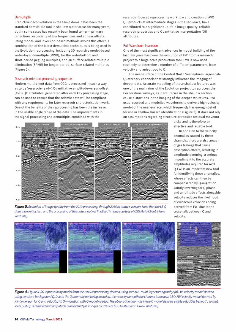
Figure 4. Figure 4. (a) Input velocity model from the 2015 reprocessing, derived using TomoML multi-layer tomography; (b) FWI velocity model derived
using constant background Q. Due to the Q anomaly not being included, the velocity beneath the channel is too low; (c) Q-FWI velocity model derived by
joint inversion for Q and velocity; (d) Q-migration with Q model overlay. The absorption anomaly in the Q model delivers stable velocities beneath, so that
local pull-up is reduced and amplitude is recovered (all images courtesy of CGG Multi-Client & New Ventures).
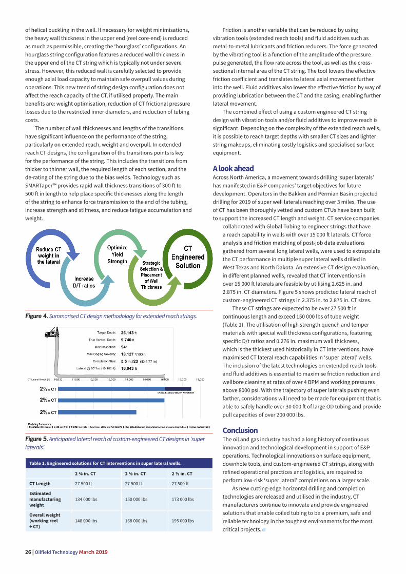
Figure 5. Evolution of image quality from the 2010 processing, through 2015 to today’s version. Note that the LS-Q
data is an initial test, and the processing of this data is not yet finalised (image courtesy of CGG Multi-Client & New
Ventures).

Q-FWI results show good conformance with geology and
seismic structures. The Q-FWI successfully identifies the shallow
glacial channels and their associated velocity and absorption
anomalies, to deliver a more stable velocity field beneath them
(Figure 4). The reprocessed data shows much sharper features
than the legacy processing results, with better well ties and
therefore more reliable depth imaging.
ConclusionThe Cornerstone Evolution project clearly demonstrates the value
that even legacy data can contribute when reprocessed. For the
priority area discussed here, the older data was processed in
combination with newer acquisitions to deliver DAZ coverage. In
other areas of the full project there is only single-azimuth data,
some of which was acquired with broadband technology and is only
a couple of years old, and some of which is conventionally acquired
data. Figure 5 shows the evolution of data
quality from the initial 2010 processing to
today’s DAZ Least-Squares Q-PSDM. The
Least-Squares Q-PSDM panel is only an initial
test. Unlike the other DAZ panels, which
have been processed through a full DAZ
sequence, each azimuth has been processed
individually and then been stacked together
with 50% weights. Further improvements
are expected when this has been processed
through a proper DAZ sequence.
The entire 35 000 km2 Cornerstone
project is being combined and reprocessed
through the new sequence. This will deliver
a seamless, contiguous volume of the
highest-quality reservoir-ready data. An
early-out volume will be available during
the third quarter of 2019.
CGG has recently reprocessed several
of its older seismic data sets around the
world, in some cases combining them
with new acquisition, to deliver large
contiguous volumes of modern, broadband,
pre-stack depth-migrated seismic data.
These large-scale projects include over
100 000 km2 of data in the Santos and
Campos Basins, 38 000 km2 in the Perdido
fold belt in the Mexican Gulf of Mexico, and
11 000 km2 of data offshore south-east
Australia, where new, complementary
acquisition is planned. Larger surveys
deliver a better overall understanding of
a basin by providing a regional view. By
processing these surveys using the latest
advanced FWI imaging sequences, they also
have the fine resolution necessary to make
the best-informed decisions.
The rapid improvement in subsurface
imaging technology is continuing,
meaning that reprocessing is becoming
more necessary – today’s highest-quality
data will be next year’s baseline for
improvement. Nevertheless, improvements
tend to progress by incremental stages
with occasional quantum leaps. Recent
step-changes have been the introduction of
broadband data, followed some years later by the industrialisation
of FWI. The next big improvement is likely to come from extending
the improvements in azimuthal sampling, delivered by wide- and
full-azimuth surveys, from the Gulf of Mexico to more areas of the
world, even those without salt. Rich- and multi-azimuth surveys
not only benefit from improved illumination but also from the
denser fold coverage, which significantly improves signal-to-noise
ratios and attenuation of multiples. CGG is already acquiring a
rich-azimuth survey over the North Rona Ridge, Northwest of
Shetland, and various node surveys are being planned around the
world for the coming years. With this trend, ownership of legacy
data to overshoot at a diff erent azimuth will be an even more
valuable asset than it is already. Seismic data is always as good as
the day it was acquired; it does not perish, even though the media
that it is stored on may. Newer, more advanced data may deliver
improved imaging, but older data remains a valuable commodity.

A critical component
18 |

A s North American shale has continued its rebound
from 2014 lows, coiled tubing has similarly grown in
importance. Coiled tubing is facing new challenges,
largely centred around the difficulty of horizontal wells
with extended laterals as well as a wider variety of well
paths and geological conditions in expanded drilling areas.
This challenge is further impacted by the complicated
logistics of coiled tubing operations, which require
significant movement of heavy equipment. National Oilwell
Varco (NOV), recognising that the changing landscape
of coiled tubing demanded new solutions, has been
developing custom answers in response.
Enhancements for existing equipmentOne issue surrounding coiled tubing equipment is
retrofitting. It has become more common, across virtually
all drilling- and completions-related capital equipment,
to upgrade components and functionalities rather than
purchase entirely new equipment, especially as companies
remain cost-constrained and wary of unnecessary large
purchases. The need for upgrades will be especially
prevalent in 2019 and moving forward, as pressure
pumping and coiled tubing fleets have largely been built
out in 2018 on the back of the shale boom. Motley Services,
a provider of well completion and intervention services
Tom Hewitt, Jordan Lewis, and Stephen Forrester, NOV, examine the use of custom solutions to the challenges of North American coiled tubing.
| 19

20 | Oilfield Technology March 2019
in the Permian Basin, is one company recognising the value of
retrofitting. After purchasing an older coiled tubing unit at an
auction, Motley approached NOV for the prospect of an overhaul.
NOV completely stripped the unit and rebuilt it to like-new,
including more advanced equipment and a larger control cabin.
The unit was originally built for 2 in. coil, and after the upgrade
it could handle 2⅜ in. coil. This meant that the unit could handle
the larger coiled tubing necessary for longer, more difficult
laterals – and that Motley Services was equipped to provide such
services for their customers.
Logistical hurdlesAnother issue for coiled tubing equipment has been the
constraints of mobilising and operating the equipment in
different jurisdictions where highway regulations typically
differ substantially, thus restricting where the equipment is
able to legally go. Copper Tip Energy Services, a Canadian well
servicing provider offering coiled tubing, nitrogen pumping,
and fluid pumping solutions, was looking to enhance their
product offerings and add NOV coiled tubing equipment to their
current large fleet of NOV-built nitrogen units. Unfavourable
market conditions in Canada, primarily related to
pipeline constraints and discounted oil prices resulting in
reduced capital investment, presented Copper Tip with a
less-than-ideal operating environment.
Recognising that several Canadian service companies
were heading south of the border to take advantage of more
lucrative market conditions, Copper Tip sought a way to
move their equipment as well should conditions continue to
decline. Unfortunately, moving such large equipment was
not as simple as it sounds; allowable dimensions, weight,
and axle/suspension configurations dictate whether or not
something can be moved on standard roads. Without the
ability to legally move equipment between Canada and the
US, Copper Tip had little recourse other than the prospects
of doing nothing or buying two separate units configured to
the different countries’ specs. A standard configuration in
Canada is a 24 wheel, three-axle trailer suspension, while in
the US the configuration is a 20 wheel, five-axle suspension.
Neither of these are recognised in the other country, but it
was impossible to justify purchasing two units, especially
with the economic uncertainty of the Canadian unit, which
might have to sit idle for a prolonged period. Faced with this
dilemma, Copper Tip approached NOV to design a technology
that would allow a unit to travel on both sides of the border,
effectively changing the suspension to enable use in each
location.
NOV developed a new coiled tubing unit that had the
ability to interchange complete axle groups in a relatively
short time and at a minimal cost to the operator. If it is
necessary to relocate the coiled tubing unit, the alternate
suspension/axle group – the one required by the country to
which the unit is headed – is pinned into place, and the unit
can cross the border safely and legally.
Bringing together new equipment with training initiativesBridging the skills gap with new or upgraded equipment is
another important component of optimising coiled tubing
operations. Not having enough staff who can use the
equipment effectively makes the investment worthless, an
issue compounded by the financial loss and HSE concerns
should an incident occur as a result of untrained staff.
Balanced Energy Oilfield Services, Inc. is a coiled tubing
operator in the western Canadian Sedimentary basin. With a
desire to increase their market penetration in North America,
the company needed to both add equipment that would
be permittable in both markets, and hire and train new
employees to meet higher demand expectations. Working
with NOV, Balanced Energy was able to develop equipment
specifications suited to both Canada and the US. In addition,
they developed a complementary training programme to
Figure 1. The first image in the sequence shows the original unit purchased by
Motley Services, while the next two images show the unit overhauled by NOV and
the new coiled tubing reel for larger spools.

LAGCOE 2019connect explore discover
HEREThe future of energy starts
CONNECT
EXPLORE
DISCOVER
your business with the right kind of attendees, in the right place.
technical and international sessions that focus on both the onshore and offshore oil and gas industry.
the new location in New Orleans will accommodate for growth and industry trends/ needs.
COUNTRIES
Who Attends? Areas of Interest
Why Exhibit?
LAGCOE.com/expoLAGCOE.com/expoContact For Pricing & More Information
New Orleans Ernest N. Morial Convention Center | New Orleans, LA
October 9-11, 2019
In New Orleans, LA
STATES
Executives
Engineers
Engineering/Technical Management
Financial Consultants
International Delegates
OEM’s
Owner/CEO
Purchasing
Private Equity
Superintendent/Field Professional
Safety
Frac
Surface
Sand/Logistics
Completion
Drilling
Natural Gas Wellhead
Capital Equipment
Manufacturing

22 | Oilfield Technology March 2019
reduce operational and service-related issues encountered with
expansions.
Balanced Energy requested that NOV provide specific
training on the coiled tubing equipment as it was delivered. One
potential area for improvement was with coiled tubing injectors.
The coiled tubing injector grips the tubing as it is inserted or
pulled out of the well, and extremely high forces are required to
control the tubing without damage to the injector or the tubing
itself. In some instances, the coiled tubing could be a continuous
piece of steel pipe in excess of 20 000 ft and valued at more
than US$200 000, making potential damage a major concern.
Improper maintenance or operation of the injector could damage
the tubing. After implementing new training practices created
by NOV, Balanced Energy saw a significant reduction in service
issues associated with both the coiled tubing injector and the
coiled tubing. Improvement was so dramatic that the company
requested additional training on other aspects of coiled tubing
equipment and operation and, more broadly, various pieces of
intervention and stimulation equipment.
Balanced Energy found the injection operation training to be
useful and saw good results from supervisors who were enforcing
and following the new procedures. The technical background of
the instructor, coupled with NOV’s knowledge of the equipment
as the OEM, was key.
Optimised coiled tubing string designAchieving success with coiled tubing operations depends not
only on the equipment involved but also on the design of the
coiled tubing itself. To optimise coiled tubing string design, NOV
partnered with steel suppliers to develop TRUE-TAPER™ XR,
an enhancement that is designed to minimise the number of
bias welds in the tapered string and to assure a gauge-to-gauge
bias weld in each instance. While traditional tapered strings
have stress points at the bias weld juncture due to non-uniform
load transfer, the TRUE-TAPER string achieves a linear taper by
gradually varying the thickness of the flat steel strip over almost
its entire length. This reduces stress concentrations and the
number of bias welds while optimising strength-to-weight ratio
and safety factors.
Pioneer Energy Services, a provider of coiled tubing services
for well intervention and new well completion programmes,
needed a product that would help them meet the challenges of
longer laterals in unconventional shale. NOV provided Pioneer
with the TRUE-TAPER XR. Pioneer initially developed string
designs with XR tapers that could better overcome the weight
restrictions of the Rockies, which were imposed by using a
one-piece coiled unit and stricter DOT laws in the region. Given
that acceptable pipe weight maximums were much lower, the
new XR tapers allowed for hourglass string designs that had
better reach and set-down weight in their well simulations versus
non-XR taper designs. This increased performance allowed
Pioneer to reach total depth on wells that were over 4 miles in
measured depth and that could have 1 - 2 mile laterals. With
non-XR designs, reaching the required depth would have been
extremely difficult, if not impossible.
As horizontal wells with long laterals require heavy-wall
tubing in the vertical section to go beyond the heel
into the lateral, the string wall transition needs to go
from heavy wall to light wall as quickly as possible to
reduce the overall weight of the string. The XR tapers
allowed Pioneer to maximise their string lengths
while maintaining simulated performance levels and
meeting strict weight requirements. In addition to
completing projects with extended-reach laterals,
the XR tapers also provided for greater string length.
While without TRUE-TAPER XR the design would have
resulted in a shorter string length, with them the
string length could still be maintained for required
well depths even as pipe was cut during normal
string management.
Looking forwardDue to the number of problems that can develop
in producing wells, coiled tubing will remain a
critical component of intervention solutions for the
foreseeable future. As failing to address problems
with producing wells could lead to a total loss
of production over time, finding an appropriate
intervention solution quickly is key. For many
wells, the simplest considerations are well design
versus solution economics – do they match, and is
the solution financially feasible? Coiled tubing is
frequently the answer due to how time-effective
it is, and because it eliminates the typical costs of
removing the tubing from the well via a workover rig.
Combining the utility of coiled tubing with custom
solutions to problems will help companies get
ahead of the curve in this highly competitive, rapidly
evolving market.
Figure 3. On a previous project, NOV reduced the length of a 2⅜ in. coiled tubing string
design by approximately 64.5% when compared to a conventionally tapered design. The
amount of taper sections was decreased from four to two, and the total average length of
the tapers from 4315 ft to 1530 ft , with the TRUE-TAPER XR design.
Figure 2. The new coiled tubing unit, designed to allow rapid change-out of
suspension/axle groups to enable movement between countries.

Technological advances in horizontal drilling and hydraulic fracturing
created a resurgence in focus on US unconventional reservoirs,
driving the exponential increase in oil and gas production over the
last few years. These advances gave operators the ability to produce shale
oil and gas at reduced costs and continue to improve profit margins as the
wells reached higher production rates.
To optimise well productivity and economics, operators are
maximising reservoir contact while minimising surface footprint by
increasing drilled lateral lengths. As 10 000 ft has become increasingly
common and achievable, well producers continue to push the lateral
well boundaries to over 15 000 ft , creating ‘super lateral’ wells. These
wells challenge not only directional drilling, logging and completions, but
particularly coiled tubing (CT) interventions.
Well statusAs of January 2019, well laterals of more than 23 000 ft have been drilled
onshore internationally, with domestic examples of up to 19 000 ft in
length in Utica Shale in Pennsylvania. This drilling strategy has brought
advantages and eff iciencies, but oft en results in complex well trajectories
which complicate service operations throughout the life cycle of a well.
An overview of Drillinginfo shows an increased number of wells with
over 12 000 ft lateral lengths since 2013. At the same time, the number of
wells surpassing 14 000 ft lateral lengths have increased by 5% of the total
wells drilled in the same time frame (Figure 1). Figure 2 shows the US well
count of laterals featuring over 14 000 ft in the last 5 years.
According to off icial data, lateral length alone has increased
approximately 130% from 2010 to 2018 in plays such as the Niobrara and
ENHANCING ENHANCING TUBING TUBING
TECHNOLOGYTECHNOLOGYIrma Galvan, Global Tubing, USA, explores how the rise of ‘super lateral’ wells is
driving the optimisation of coiled tubing interventions.
| 23

24 | Oilfield Technology March 2019
Permian Delaware. US operators in the Bakken, Permian, Haynesville, and
Marcellus are now drilling ‘super laterals’ (Figure 3 - right chart). It can be
observed that the maximum drilled laterals in 2010 are the average well
lateral lengths in 2018.
Industry responseAs drilling technology is creating ‘super lateral’ wells, the CT industry has
developed products to satisfy demands for CT with extended capabilities,
reliability and predictability. CT service and manufacturing companies
are continuously working with operators to develop products and
technologies to remain a competitive option with deeper, longer, and more
challenging wells that continue to drive the industry.
In response to the demand, US operators have had success using CT
in well laterals of 12 000 ft to 13 000 ft in post-fracture plug mill-out and
clean-out operations by deploying 2.375 in. and 2.625 in. CT diameters
with over 23 500 ft tubing length. These CT strings use custom-built wall
thickness configurations and state of the art manufacturing technology of
high-grade materials that surpass 125 000 lbs in tube weight.
Newer models of surface CT equipment are being manufactured
to accommodate the longer CT lengths along with heavier and larger
CT strings. However, the field deployment of these massive CT rigs to
remote field locations has become a diff icult and complex challenge
due to increasing demand for larger coiled tubing units (CTU) and more
eff icient equipment mobilisation and logistics.
CT equipment manufacturers have released CTUs that are able
to handle larger tubing in line with local transportation regulation
guidelines. These new units are capable of transporting over 27 000 ft
of 2.625 in. CT weighing upwards of 160 000 lbs. CT injectors are being
redesigned or retrofitted to be able to deliver pull and snub capacities
of 140 000 lbs and 70 000 lbs, respectively.
Meanwhile, CT manufacturers such as Global Tubing are
responding to meet the ever growing demands of the industry. The
latest technological development in the CT manufacturing industry is
the implementation of an in-line quench and temper (Q&T) process,
such as HALO Induction Technology™. This process enhances the
overall CT life and predictability by producing tubing with more
uniform microstructure throughout its entire length, increased material
strength (110 000 psi to 130 000 psi yield strength), and improved bend
fatigue performance. The final product is called DURACOIL. When
DURACOIL products are combined with rapid-taper strip technology
and an advanced CT design, strings have been shown to achieve
unprecedented well lateral reach with improved service life.
Engineered CT optimisation has become an integral part of the
well intervention job design. It has progressed to a complex process
that requires a multifaceted understanding of well conditions,
CT working pressures and axial loading boundaries, low cycle
fatigue, forces, stresses and fluid mechanics expected during
the operation. CT surface equipment capabilities and regional
transportation logistics are also considered during the string
design optimisation.
With this new generation of large diameter CT strings
that exceed 24 000 ft in length and 130 000 lbs in weight, one
of the critical challenges is the current mobilisation weight
constraints of the CT surface equipment (reel and trailer). As
mentioned previously, CT equipment manufacturers have paced
their releases with the market demand of handling heavier CT.
However, the existing weight restrictions continue to limit the
maximum wall thickness that can be used in the CT design,
which aff ects the stiff ness and horizontal reach capacity of that
specific CT string design.
Engineered approachCT design methodology followed by Global Tubing has
modernised the CT manufacturing industry and enabled CT
service providers to support the requirements of operators (see
summarised methodology in Figure 4). This design criteria has
been proven to increase CT performance in extended reach
well operations, as well as increasing useable service life while
conforming to surface equipment design constraints.
The process starts by reducing the
CT weight in the horizontal section of
the well. The CT weight can be reduced
by increasing the diameters to wall
thickness ratios (D/t) in the downhole
end, achieved by decreasing the wall
thickness as much as possible. To
retain mechanical properties, the
material yield strength is increased
to compensate the pressure and axial
load capacity. The process continues
by strategically selecting and placing
various wall thicknesses along the
length of the CT string to improve
bending stiff ness and avoid the onset
Figure 1. US well count of +10 000 ft laterals lengths (Source: Drillinginfo).
Figure 2. US well count of +14 000 ft laterals lengths (Source: Drillinginfo).
Figure 3. Maximum lateral length per US shale comparison 2010 (left ) versus 2018 (right) (Source: Drillinginfo).

Subscribe online at: www.oilfi eldtechnology.com/subscribe
Global Publication
A global industry requires a global
publication
26 | Oilfield Technology March 2019
of helical buckling in the well. If necessary for weight minimisations,
the heavy wall thickness in the upper end (reel core-end) is reduced
as much as permissible, creating the ‘hourglass’ configurations. An
hourglass string configuration features a reduced wall thickness in
the upper end of the CT string which is typically not under severe
stress. However, this reduced wall is carefully selected to provide
enough axial load capacity to maintain safe overpull values during
operations. This new trend of string design configuration does not
aff ect the reach capacity of the CT, if utilised properly. The main
benefits are: weight optimisation, reduction of CT frictional pressure
losses due to the restricted inner diameters, and reduction of tubing
costs.
The number of wall thicknesses and lengths of the transitions
have significant influence on the performance of the string,
particularly on extended reach, weight and overpull. In extended
reach CT designs, the configuration of the transitions points is key
for the performance of the string. This includes the transitions from
thicker to thinner wall, the required length of each section, and the
de-rating of the string due to the bias welds. Technology such as
SMARTaper™ provides rapid wall thickness transitions of 300 ft to
500 ft in length to help place specific thicknesses along the length
of the string to enhance force transmission to the end of the tubing,
increase strength and stiff ness, and reduce fatigue accumulation and
weight.
Friction is another variable that can be reduced by using
vibration tools (extended reach tools) and fluid additives such as
metal-to-metal lubricants and friction reducers. The force generated
by the vibrating tool is a function of the amplitude of the pressure
pulse generated, the flow rate across the tool, as well as the cross-
sectional internal area of the CT string. The tool lowers the eff ective
friction coeff icient and translates to lateral axial movement further
into the well. Fluid additives also lower the eff ective friction by way of
providing lubrication between the CT and the casing, enabling further
lateral movement.
The combined eff ect of using a custom engineered CT string
design with vibration tools and/or fluid additives to improve reach is
significant. Depending on the complexity of the extended reach wells,
it is possible to reach target depths with smaller CT sizes and lighter
string makeups, eliminating costly logistics and specialised surface
equipment.
A look aheadAcross North America, a movement towards drilling ‘super laterals’
has manifested in E&P companies’ target objectives for future
development. Operators in the Bakken and Permian Basin projected
drilling for 2019 of super well laterals reaching over 3 miles. The use
of CT has been thoroughly vetted and custom CTUs have been built
to support the increased CT length and weight. CT service companies
collaborated with Global Tubing to engineer strings that have
a reach capability in wells with over 15 000 ft laterals. CT force
analysis and friction matching of post-job data evaluations
gathered from several long lateral wells, were used to extrapolate
the CT performance in multiple super lateral wells drilled in
West Texas and North Dakota. An extensive CT design evaluation,
in diff erent planned wells, revealed that CT interventions in
over 15 000 ft laterals are feasible by utilising 2.625 in. and
2.875 in. CT diameters. Figure 5 shows predicted lateral reach of
custom-engineered CT strings in 2.375 in. to 2.875 in. CT sizes.
These CT strings are expected to be over 27 500 ft in
continuous length and exceed 150 000 lbs of tube weight
(Table 1). The utilisation of high strength quench and temper
materials with special wall thickness configurations, featuring
specific D/t ratios and 0.276 in. maximum wall thickness,
which is the thickest used historically in CT interventions, have
maximised CT lateral reach capabilities in ‘super lateral’ wells.
The inclusion of the latest technologies on extended reach tools
and fluid additives is essential to maximise friction reduction and
wellbore cleaning at rates of over 4 BPM and working pressures
above 8000 psi. With the trajectory of super laterals pushing even
farther, considerations will need to be made for equipment that is
able to safely handle over 30 000 ft of large OD tubing and provide
pull capacities of over 200 000 lbs.
ConclusionThe oil and gas industry has had a long history of continuous
innovation and technological development in support of E&P
operations. Technological innovations on surface equipment,
downhole tools, and custom-engineered CT strings, along with
refined operational practices and logistics, are required to
perform low-risk ‘super lateral’ completions on a larger scale.
As new cutting-edge horizontal drilling and completion
technologies are released and utilised in the industry, CT
manufacturers continue to innovate and provide engineered
solutions that enable coiled tubing to be a premium, safe and
reliable technology in the toughest environments for the most
critical projects.
Figure 5. Anticipated lateral reach of custom-engineered CT designs in ‘super
laterals’.
Figure 4. Summarised CT design methodology for extended reach strings.
Table 1. Engineered solutions for CT interventions in super lateral wells.
2 ⅜ in. CT 2 ⅝ in. CT 2 ⅞ in. CT
CT Length 27 500 ft 27 500 ft 27 500 ft
Estimated
manufacturing
weight
134 000 lbs 150 000 lbs 173 000 lbs
Overall weight
(working reel
+ CT)
148 000 lbs 168 000 lbs 195 000 lbs

The process of optimising a horizontal completion is typically a series of
trial-and-error adjustments designed to improve well productivity. As changes
to the treatment schedule and/or perforation scheme are implemented,
the eff ectiveness is judged by comparing the production of the new well to the
production of off set wells. However, most operators agree that this optimisation
process could benefit significantly from additional feedback. For instance,
when there is an observed diff erence in production between the new well and
neighbouring wells, is it caused by variations at every stage – or is it just a few
stages that are underperforming or overperforming? It would also be valuable to
be able to diff erentiate between productivity variations that result from changes in
the completion design versus changes due to heterogeneity in the geological facies
along the lateral.
There are several commercial technologies in the market that attempt to address
these questions. A few examples include hydraulic frac monitoring using microseismic,
production logging and tracer logs. While these techniques have been used successfully
in some instances, none have proven valuable enough to be universally accepted.
The biggest challenge is that they are diff icult to deploy and require a lot of planning
on the part of the operator. And, because diff icult deployment translates to increased
expenses, most operators are willing to consider using these technologies only if they
are foolproof, easy to use and provide complete diagnostic insight. Unfortunately, this
CollaborativeCollaborative
CompletionsDale Logan, C&J Energy Services and Panos Adamopoulos, Seismos, USA, examine a combination of new technologies designed to optimise horizontal completions.
| 27

28 | Oilfield Technology March 2019
is not the case with any of them, so they are relegated to exist as niche
players within the shale industry.
Simple deployment delivers sophisticated dataThe new Seismos-Frac™ service targets this shortcoming with a
simple, noninvasive method that delivers a direct, comprehensive
measurement of fracture-network properties. Seismos’ approach
uses a combination of ambient noise and induced, tube-wave
pressure pulses to investigate the hydraulic fracture network. The
measurements delivered include frac geometry (width, height and
half-length), as well as near- and far-field characterisations of fracture
network complexity, fracture conductivity and proppant placement.
These results are produced on a stage-by-stage basis in near-real time,
normally within 10 minutes of the completion of pumping. This enables
the operator to review the measurements, assess the performance of a
given stage and then use any learnings on successive stages.
The service is relatively aff ordable because it uses a
straightforward installation process that is virtually plug and play.
A pair of pressure transducers is installed at surface, which can
typically be done in less than an hour. During the completion process,
ambient noise is analysed, and pressure pulses are sent down the
fluid column to investigate the perf clusters – both before and aft er
fracturing operations. This can be done without any interruption
to the on-location completions team. As a result, this technology is
particularly well suited to the industrialised environment of today’s
shale industry.
Collaboration is keySeismos-Frac technology has been available in the field since
2017 and has been deployed on roughly 110 wells to date. Early
evaluations show that variability in frac geometry and conductivity
from stage to stage is not only common, it is oft en the norm. The
two most frequent causes for these variations are changes in the
treatment schedule and changes in the rock properties along the
horizontal wellbore. To isolate the two sources of variability, Seismos
encourages operators to use the Seismos-Frac service alongside
C&J Energy Services’ LateralScienceSM method. This method uses
existing drilling data to evaluate changes in rock mechanics along the
lateral. As with the Seismos-Frac service, the LateralScience method
is delivered in an aff ordable, noninvasive manner, which makes the
tandem technologies a natural fit into any completion workflow.
Quantitative data tells the storyIn a recent well, this collaborative approach was put to the test.
In part one of the test, a group of seven stages was completed
using 57% less proppant and 38% less slurry than a comparable
group of stages with similar rock properties (as indicated by the
LateralScience facies). For the subject test group, the Seimos-Frac
geometric results indicated 35% less half-length, exactly the same
height and slightly higher frac width. Qualitatively, these results
make perfect sense – and, since the goal was to achieve a shorter
half-length (to avoid frac hits), the operator was pleased.
In part two of the test, a group of 16 stages drilled in
lower-strength rock was compared to a group of eight stages drilled
in higher-strength rock. The treatment schedule and completion
design were held constant between the two groups. In this scenario,
the lower-strength rock delivered half-lengths that were 24% longer,
accompanied by far-field fracture conductivity that was 30% lower
than in the higher-strength rock. Once again, this result is consistent
with a lower-strength interval creating more planar fractures that
extend farther from the wellbore, which distributes the proppant
across a larger area and therefore produces a lower average
conductivity index. Qualitatively, this is consistent with Nolte plot
interpretations made on previous wells, and a quantitative value
can now be assigned to the impact observed.
Better information delivers better valueThe value of Seismos-Frac measurements is obvious to experts
in the completion engineering domain, and this value goes
well beyond optimising the completion design. The principle
applications that operators have identified as most valuable include
the following:
Well-to-well optimisation
New field developmentThis application can be extremely valuable when an operator is
moving into a new area and trying to determine what works and
what does not. It can provide clarity on what the fracture system
looks like and what well spacing might be most appropriate. It
can also provide insight into understanding correlations between
stimulation designs, geology and fracture-network properties.
Sensitivity studiesSeismos-Frac measurements can also quantify how sensitive
the completion is to any changes implemented in the treatment
schedule. It is not unusual for operators to experiment with
changes in slurry volumes, pump rates, proppant concentrations,
chemical additives, etc. Real time, quantitative feedback on how
these changes impact fracture geometry and fracture-network
properties aff ords the operator greater insight to help decide
whether to adopt a new completion approach. In addition to the
real time value brought by sensitivity studies on a stage-by-stage
basis, they are also useful aft er the fact to plan for the next well.
Stage-to-stage optimisation (real time)
Completion optimisationWhen operating in well-understood areas, the value of these
measurements is realised in real time, stage-by-stage completion
optimisation. The original treatment schedule assumes an
anticipated geometry and set of fracture-network properties. The
metrics that most completion engineers use to gauge fracturing
performance are pounds of proppant per lateral foot or barrels
Figure 1. This graphic representation shows the LateralScience facies (indicated
in trajectory plot) combined with Seismos-Frac results for both geometry (blue)
and conductivity (green). Lower-strength stages at the heel show much longer
half-lengths than the high-strength stages further downhole.

March 2019 Oilfield Technology | 29
of treatment fluid per lateral foot. When wells perform outside of
expectations, they presume it is related to these metrics or that it is due
to poorly distributed proppant. By monitoring each stage, compliance
can be assessed and the treatment adjusted as needed. When
adjustments are required, the monitoring also provides measurements
to quantify the impact of each treatment change to the resulting
fracture system.
Zipper fracsWhen it is time to develop the field, most operators move to pad
drilling and zipper fracs. The tighter well spacing introduces issues
like potential interference between wells and even frac hits. In
this case, understanding the frac height and half-length is critical
to ensure compliance. This allows the operator to approach the
completion aggressively while avoiding excessive frac length that
could be detrimental to production.
Operational assuranceIn some scenarios, the focus will be on operational eff iciency. By
monitoring treatments on the fly, an operator can detect issues – such
as leaking plugs, hydraulic communication with previous stages or
even screenouts – as they develop. Providing an additional tool to
detect these events enables the operator to do a better job of reacting
to them and ultimately in adjusting the approach to avoid them.
Delivering resultsAs discussed above, this service has the potential to change how the
completion workflow is performed in the field. However, to transform
this potential into tangible value, the plans put together at the head
off ice must be well aligned with what is actually happening in the
field. Experience has shown that there can be significant ‘value
leakage’ at the field level if this is not properly addressed. This is
the primary driver in the alliance formed between Seismos and C&J
Energy Services.
Seismos believes value leakage can be minimised by aligning
its Seismos-Frac off ering with a service provider that is fully vested
in the success of the service. It starts at the front lines, where C&J’s
frac engineers are trained to understand both LateralScience and
Seismos-Frac technologies – as well as how the two complement
each other. On-site engineers are fully briefed on both the
overarching objectives of the survey and the expected results. It
is very important that the person in charge of executing the job
understands completely how each specific action will impact the
success of the survey. While communication with the head off ice is
important, communication between the frac van and the Seismos
trailer is vital. When this is done seamlessly, the odds of success
increase significantly.
Setting the stage for the next generationAs with any groundbreaking technology, growth and adoption follow
a distinct life cycle – and these are still the very early days of the
Seismos-Frac off ering. While the service is being embraced by the
industry, it is still in the evaluation phase as operators continue to
test it and become comfortable with the results they are getting.
Equipment and people are being added as quickly as practical to
meet the demand. Pioneering technologies will enable the next
generation of engineers to make better-informed decisions and
ultimately deliver more oil and gas with ever-greater eff iciency. The
Seismos-Frac and LateralScience collaboration provides a preview of
what that will look like.
GLOBALPETROLEUMSHOW.COM
GPS FAST FACTS
NORTH AMERICA’S LEADING ENERGY EVENT
JUNE 11-13, 2019C A L G A RY, C A N A D A
REGISTER NOW!
460,000+ Gross sq ft
1,000+ ExhibitingCompanies
100+ Expert Speakers
50,000+ Attendees
10 NOCs
30 IOCs
600+ ConferenceDelegates
60+ TechnicalSessions
115+ CountriesRepresented
BUY YOUR 3-DAY STRATEGIC CONFERENCE PASS FOR $695
BUY YOUR 3-DAY TECHNICAL CONFERENCE PASS FOR $695
EXHIBITION | CONFERENCE | AWARDS

Developing Developing a digital a digital futurefuture
Manoj Nimbalkar, Weatherford International, USA, discusses recent advances in digital and cloud-based technology designed to
drive oilfield productivity.
Safely producing more barrels at a lower cost is
the common, industry-wide goal for operators
– despite increasingly challenging operating
environments and constant fluctuations in economic
cycles.
In response, the oil and gas industry has devised
innovations across each phase of the well lifecycle –
exploration, drilling, completion, and production – to
extract hydrocarbons eff iciently and cost-eff ectively.
For example, in the past operators have leveraged
innovations in exploration, drilling and completion
to drill more wells in sweet spots, add more fracture
stages per well, and pump more proppant per stage to
boost production. However, this solution has plateaued
in terms of eff iciency. New, innovative completion
designs – including intelligent completions – have
helped to foster a production renaissance in the US,
but unless a major step change in technology occurs,
the benefits yielded from these solutions will plateau
as well.
With no major technological advances introduced
since the advent of artificial lift , the production phase is
the next frontier for realising significant eff iciency gains
and cost reductions. Leading the way is the increasing
adoption of technologies that incorporate components
of Industry 4.0.
Industry 4.0 and Production 4.0The world is currently undergoing a fourth industrial
revolution. During the first revolution in the
nineteenth century, industries embraced water and
steam-powered mechanisation for the production of
commercial goods from large, centralised factories.
In the second revolution during the early part of
the twentieth century, electric power enabled mass
production and assembly-line creation of goods
such as automobiles. During the latter half of the
twentieth century, the third revolution introduced
computers, automation, and robotics. Aff ordable
semiconductors brought computers into customers’
homes and eventually their pockets. All three of
these previous revolutions maximised productivity
and eff iciency while reducing costs.
For decades, digitalisation has increasingly
served as a vehicle for achieving these goals,
especially in oil and gas. However, the paradigm of
30 |

Industry 4.0 – the fourth revolution – has altered not
just how digital technologies are used, but also how
organisations think and operate on a larger scale.
Industry 4.0 is about linking technologies so they
can better communicate with each other and make
business or operational decisions without human
involvement. While other technology-driven industries
have already started their transformation journey, the
oil and gas industry has just started implementing
Industry 4.0 technologies. Early results indicate that
it has introduced eff iciencies in accessibility and
computing, and has allowed operators to better
exploit their most valuable asset: their data.
Four components comprise Industry 4.0. First, the
Internet of Things (IoT) links groups of physical devices so
they can communicate, and allows remote monitoring
and control. This increases access to data, broadens the
scope of viewable data, and helps to drive systematic
eff iciencies.
Second, cloud computing – using a network of
remote, Internet-hosted servers to store and manage
data in a secure environment – enables users to access
data from anywhere and on any desktop, tablet, or
mobile device while reducing technology infrastructure
and the associated installation, maintenance, and
support costs. Companies can choose to use the public
cloud or a private, internal cloud. This helps users to
connect with data in a fast, direct, and meaningful way,
which is especially helpful for industries – such as oil and
gas – that generate large volumes of data over several
years.
Third, edge computing connects intelligent devices to
current and historical data so that autonomous decisions
can be made where they matter most – at the wellsite.
In the oil and gas industry, this means that lower-level,
day-to-day decision making can be transferred to
autonomous computers, which frees personnel to focus
on higher-priority projects and tasks while reducing
overall staff ing needs at remote wellsites.
Fourth, advanced analytics brings the concepts of IoT,
cloud computing, and edge computing together to create
an interconnected, intelligent ecosystem that enables
operators to glean meaningful, actionable insight from
data. Letting operators see entire enterprises by function,
asset, well, or any other level from a single dashboard,
analytics aids in the identification of anomalies and
trends along with opportunities to improve eff iciencies,
predict future performance, optimise production, and
maximise profits. Furthermore, instead of serving a
purely mechanical function, analytics helps oilfield
equipment to act as intelligent machines that learn and
teach themselves to enhance eff iciency, predict failures,
and manage assets by exception. This avoids error-prone
human judgment and thus provides proactive well
maintenance rather than reactive well repairs.
When the components behind Industry 4.0 are
applied to the management of oil and gas production
performance, Weatherford refers to it as Production 4.0.
Creating Production 4.0 technology – software A component of Production 4.0 technology that has
proven highly useful to oil and gas operators is the
Weatherford ForeSite production-optimisation and
CygNet SCADA soft ware. To date, these platforms
monitor and optimise 460 000 wells around the world
daily, monitor 125 000 miles of oil and gas pipeline, and
manage 30 billion data updates every day.
ForeSite soft ware acts as a field-wide intelligence
platform with the ultimate goal of optimising the
eff iciency of production, maximising production volume,
increasing the run life of equipment, extending the life
of assets, and making production as profitable and
economically viable as possible.
Currently, the platform’s nodal-analysis engine is
the only technology capable of monitoring all forms of
artificial lift . The Everitt-Jennings algorithm provides load
computations at multiple points along the rod string for
reciprocating rod lift , and – in combination with the Gibbs
method – is the only platform capable of computing
the downhole dynamometer card in two diff erent
ways. In this fashion, asset performance is continuously
monitored on a remote and automated basis.
The information is then displayed in an intuitive
and visual interface – in either a map or dashboard
mechanism – that allows for real time performance
analysis, the diagnosis of potential performance
problems, the identification of opportunities for
| 31

32 | Oilfield Technology March 2019
operational improvements, and more informed decision making.
Currently, the ForeSite soft ware platform is the sole provider of
enterprise-level optimisation for all forms of artificial lift , naturally
flowing wells, pipelines, and surface facilities around the world.
Using artificial intelligence combined with machine learning and
physics-based models, the platform is designed to help predict failure
by lift component. This capability – currently available for rod lift and
ESP (electric submersible pump)-lift ed wells – enables operators to
pro-actively dispatch maintenance crews when needed to reduce
downtime and associated production losses.
Operational realities can restrict the time and resources
available to install and support on-site solutions. A low barrier to
implementation makes cloud-based soft ware platforms simple
to install, maintain, and use. The ForeSite soft ware platform is a
web-based system that is reliably hosted with Google Cloud or installed
on premise. Users have complete ownership and control of their data,
and can access data on the go, from anywhere.
Separation is provided between process controls and the
business network. Fully compliant with security best practices, all
data monitored through the soft ware platform is stored on the cloud.
Another major benefit is system elasticity. With cloud computing,
users can create a production ecosystem that is both scalable and
flexible. As enterprises expand in well count or asset base, cross
geographical borders, or increase in complexity, cloud solutions let
users easily capitalise on business opportunities without incurring
additional costs.
Creating Production 4.0 technology – next-generation automation Pairing this soft ware platform with Cloud computing, IoT-enabled
communication, and next-generation automation delivers
Production 4.0 at the wellsite, or ‘on the Edge’. This combination
can acquire and store a stream of high-frequency data at the
wellsite, off ers secure communication in the form of IoT-based
instant notifications, provides optimisation models on the Edge,
and enables autonomous control. In other words, it incorporates all
the components of Industry 4.0 into one product – ForeSite Edge.
Using technology on the Edge, operators can gather both
historical-trend and real time production data from instruments
and sensors across the asset. With a capacity to access years of
sub-second, real time sensor data from the wellsite, Production
4.0 systems, in future, can then use a suite of comprehensive
calculation and modelling engines – including physics-based well
models – to optimise production. Users can even import models
from third-party technologies.
These Edge systems also deliver instant, intelligent IoT-based
data notifications. For example, operators can be alerted
immediately when sensors detect variances in performance or
trends, failures or imbalances in equipment, when slugging occurs
in wells, or when operating parameters pass critical limits. Alerts
can be sent to any device, upon which users can respond and take
corrective action in real time.
Further, Edge platforms today can deliver predictive analytics
at the wellsite by monitoring the performance of a reciprocating
rod-lifted or ESP-lifted system. Edge systems can analyse artificial
lift performance and predict when the systems will fail.
This IoT-based controller also makes daily operational
decisions and autonomously optimises production using
enterprise-wide data and the insight gleaned from modelling and
analysis on the Edge. As an example, one common problem that
the controller can help to resolve is managing idle time for rod
pumps. The system dynamically manages idle time to eliminate
the extreme scenarios of over-pumping, which causes equipment
failure, or under-pumping, which in turn leaves valuable
hydrocarbons behind in the well. The ForeSite Edge device
integrates the autonomous controller, optimisation software and
IoT gateway. Alternately, the device can also upgrade any legacy
controller – meaning operators can enjoy the benefits without
having to change their existing controller.
The overarching advantage is that data collection and
lower-level daily operational tasks that improve production
outcomes are placed on autopilot.
ConclusionThe oil and gas industry is typically slow to adopt next-generation
digital technologies in the upstream production space. But there
are many compelling reasons for operators to harness the power
of Production 4.0. Most importantly, these technologies off er the
potential to improve oilfield productivity significantly – producing
more barrels in a safer, less risky manner while reducing costs.
The advantages of implementing Production 4.0 technologies
extend far beyond advancing oilfield operations. The transition
to these newer technologies will help operators to fill gaps in the
workforce, especially aft er the industry has experienced a series
of economic downturns. There is an opportunity to discover new
talent and create a workforce that strikes the right balance between
technical and technological brainpower. Although traditional oil
and gas disciplines such as engineering are and will remain critically
important, the industry also needs expertise in digital operations,
soft ware engineering, and data science.
Digital technologies will also play a more varied role in
the future of the oil and gas industry. With functionalities and
capabilities that are in no way limited to the production phase,
operators can leverage these technologies to improve R&D and
manufacturing, for example. This is the way of the future, and will
help to drive meaningful results for operators.
Figure 1. Available on any platform, the ForeSite now provides
predictive failure analytics for ESP systems and complete optimisation
capabilities for plunger-lift ed wells. ForeSite is now edge-computing
ready, paving the way for the next-generation automation system.

Even aft er all of the prep work is finished – surveys completed,
seismology reports assessed, funding secured, permits
procured, contracts signed, wellbores drilled, production
equipment installed, product recovery initiated – there is still no
surefire way for oilfield exploration and production companies to
confidently know just how much recoverable oil and gas their wells will
produce and how long they will remain productive.
Thinking Thinking outside outside the boxthe box
Andrew Poerschke, Teddy Mohle and Paul Ryza, Apergy, discuss a new
approach to implementing artificial gas lift designed to improve production in
declining wells.
| 33

34 | Oilfield Technology March 2019
There is a simple reason for that: no two wells, even if they are
located mere yards from each other, possess the same production
and life-cycle characteristics.
While this uncertainty can be frustrating for oilfield operators
who need to show their investors with some level of accuracy what
their capital investment is actually buying them, it does create some
opportunities. Namely, the opportunity for oilfield engineers to
employ some outside-the-box (or wellbore) thinking when trying to
identify ways to flatten each individual well’s inevitable decline curve,
which will result in more predictable production rates and higher
monetary returns over a longer period of time.
Surveying the fieldA US-based energy company purchased acreage in Texas’ Permian
Basin – the largest petroleum-producing basin in the country
– specifically, Pecos County, in the Southern Delaware Basin’s
Wolfcamp A and Wolfcamp B formations. Most of the company’s
drilling locations there are horizontally fractured wells with depths
ranging between 9500 and 10 500 ft with flowing bottom-hole
pressures (FBHP) of anywhere from 5000 - 6000 psi. On average, each
well has 50 fraccing stages and requires 2250 - 2500 lbs of sand/ft and
60 - 80 bbls of water/ft .
The energy company’s objective was to create an economically
viable production trend for each individual well, knowing that the
wells could produce from anywhere between 20 and 40 years, and
also realising that it costs money to abandon an underperforming or
played-out well. It is an inescapable fact of oilfield life that as soon as the
well begins producing on the first day its decline phase begins. That is
why the operator, as mentioned, will incorporate any means necessary
to make the decline curve as flat and long-lasting as possible, which will
help optimise the production company’s return on investment.
Again, while acknowledging that each well is unique, the wells in
this formation generally have strong bottom-hole pressures, but fail to
flow naturally for an extended period of time in this part of the basin.
This means that they will require some form of artificial lift earlier in
their operational window in order to keep them flowing. For example,
the characteristics of Southern Delaware wells are such that they may
only flow for 90 to 120 days before needing artificial lift , while wells that
appear similar and are located just a few miles away may flow for more
than two years before requiring intervention.
Over the years, the default artificial lift system that has
been deemed most eff ective is one that features an electrical
submersible pump (ESP) installed in the well. However, in the
Southern Delaware Basin, this approach could be problematic for three
main reasons:
The remote areas of West Texas that are home to the
Permian Basin do not always have access to reliable electricity.
If power is not readily available in all areas of the basin,
building a power grid can cost millions of dollars.
If an operator is set on using alternative high-volume lifts, a
natural gas generator that can convert natural gas into electricity
can be rented, but this would add significant cost to the bottom
line of the operator’s lease operating expenses (LOE).
Other forms of artificial lift may have a high upfront cost, as much
as 10 to 20 times more than a set of gas lift valves.
Realising that using other forms of high-volume lift can be
cost-prohibitive, for a possible solution, the producer reached out
to Apergy, a provider of technologies to help oil and gas production
companies optimise their returns safely and eff iciently. Their main
request was a challenging one: get as much oil and natural gas out of
the well as possible in the first 90 days of operation, while reducing the
well’s LOE over its production life cycle.
Figure 1. Well 1.
Figure 2. Well 2.
Figure 3. Well 3.
Figure 4. Well 4.

Seeing is believingThe client was not averse to using alternative lift s, no matter the cost,
if reaching the goal of maximised rates could be realised, but Apergy’s
oilfield engineers knew there had to be a more cost-eff ective way to
tackle the problem. What they eventually developed was a four-pronged
approach to introducing gas lift to a series of 10 Wolfcamp A and B wells.
The trial involved introducing to the wells, at four specific points
during their operational lifetimes, a gas lift system that featured annular
gas injection:
Option A: well flows for 90 days before annular gas lift is installed.
Option B: well flows for 15 - 45 days before annular gas lift is installed.
Option C: annular gas lift is installed on the first day the well begins
flowing.
Option D: annular gas lift is installed on the first day the well begins
flowing, while injecting gas in the first few days of producing.
The first two options did not really represent a radical departure
from accepted norms. Options C and D, on the other hand, are solutions
that very few, if any, production companies will consciously choose to
implement.
Ten individual wells were tested: one well with Option A, the next
three with Option B, three with Option C and the final three with Option
D.
Well 1Well 1 began producing in early February 2017, but by the end of April
was beginning to experience daily oil and natural gas production
declines, though water-recovery rates had remained steady. Staying on
the existing course likely meant an early death for the well, but as soon
as the annular gas lift was installed at the 90 day mark, the production
curve bumped up and remained steady, save for some small peaks and
valleys, through June of 2018.
Figure 5. Well 5.
Figure 6. Well 6.
INTEGRITY 2019INTERNATIONAL ONLINE PIPELINE CONFERENCE
#Integrity19
18 - 19 June 2019
With participation from:
worldpipelines.com/integrity

36 | Oilfield Technology March 2019
Wells 2 - 4Well No. 2 was a similar story to Well No. 1: strong early production
that had already begun to taper off before the 90 day mark, when
annular gas lift was installed, which stabilised production at a rate
that remained relatively steady. Annular gas lift valves were installed
aft er only 15 to 45 days of operation. The result was a much more
gradual decline in production rates over the following months of
operation. In fact, the wells’ returns beat the engineer’s forecast
by such a significant margin that they were used as an example
for investors that illustrated how their return on investment could
improve as a result of this well setup.
Wells 5 - 7 These were the results that the engineers had been anxious to see
since the setup – the annular gas lift application deployed from the first
day of the wells’ operation was departure from accepted operational
norms. All three wells began operating in 2018 and the results have
been similar for all of them – strong production rates from day one that
have continued with only small valleys experienced (this is attributable
to some operational anomaly like a compressor failure or other
maintenance issue). If there has been one standout performer among
the four, it has been Well 7, which showed an absolutely negligible
decline curve over its first three months of operation.
Wells 8 - 10 The last wells had annular gas lift valves installed with injected
gas within the first few days that the well began flowing. Based on
the significant return, negligible decline curve, and optimised LOE,
the operator decided to treat all of its future wells in the Southern
Delaware Basin in this fashion from now on.
Overall, there are several key takeaways that can be analysed
when considering how these wells performed based on the four
diff erent gas lift setups:
Adding a velocity string during flowback reduced slugging and
outproduced casing flow.
Switching from annular gas lift to conventional gas lift did not
improve production at 2500 bpd total fluids.
When the injection gas was turned off after the first 90 days of
injecting, the wells loaded up immediately.
Production results compared to other forms of high-volume
lift were similar and, in some cases, surpassed due to lack of
downtime, but at a fraction of the cost.
ConclusionIn a complex industry like oil and gas exploration and production,
which features so many diff erent well-to-well variables that need to be
considered when determining the best way to produce the well, there
simply can be no one-size-fits-all solution. However, that randomness
can be an advantage for oilfield operators who are willing to consider
non-traditional ways to get the oil and gas to the well’s surface.
While many companies continue to rely on alternative
high-volume lift s, or waiting to introduce artificial lift systems until
the last possible moment before the well loads up, the companies
that retain an open mind are finding that there are some noteworthy
alternatives available. Based on the from-the-field empirical
information noted above – not from just one isolated well, but from
10 notable well sites in the most fertile oil and gas reservoir in the
US – one of the more successful next-generation approaches can
be to intentionally install an artificial lift system earlier in the well’s
life, up to and including the first day of operation. This is proving
to be another way to skin the proverbial cat, with the results so far
speaking for themselves. Figure 10. Well 10.
Figure 9. Well 9.
Figure 8. Well 8.
Figure 7. Well 7.

The CNPC Liaohe Oilfield Shuguang Oil Production Plant – located
some 560 km east-northeast of Beijing – used conventional
oil-removal techniques to treat contaminated water generated
during oil extraction before reinjecting the produced water into the oilfield
reservoir. Over time, though, the reservoir had become nearly saturated
and could no longer receive reinjected water. The Design Institute for CNPC
Liaohe Oilfield Shuguang (DI), therefore, developed a plan to implement
additional produced water treatment measures and discharge the newly
treated water into the Raoyang River, a tributary of the Liao River.
In May 2015, however, China’s Ministry of Environmental
Protection implemented revised discharge limits for the refinery and
petrochemical industries. The new standards established some of the
most stringent eff luent quality limits in the world. To meet the standards,
the DI designed a robust, four-train activated sludge treatment system
to help remove water soluble organics (WSOs) followed by multimedia
filtration.
Yet the produced water generated by the Shuguang plant proved
diff icult to treat. The water chemistry contains large amounts of
WSOs (measured as chemical oxygen demand or COD) resistant to
biological treatment. Despite the best eff orts of the new wastewater
plant’s operating teams, the new system could not reliably achieve the
discharge standard of 50 mg/l COD. The DI approached Siemens Water
Keeping things crystal clear
Simon Larson, Siemens, Sheng Kun Sun, CNPC, and Xiao Ming Sun, Liaohe Petro Engineering Company, review water treatment measures designed to
comply with China’s tough new treatment standards.
| 37

38 | Oilfield Technology March 2019
Solutions for help in designing modifications to the treatment plant
that would produce eff luent quality consistently meeting the extremely
challenging COD limit.
Solutions start with good scienceTable 1 presents the produced water feed characteristics and final
treated eff luent target concentrations required for discharge to the
Raoyang River.
Siemens’ team of field services personnel conducted a bench-scale
proof-of-concept study using final eff luent samples from the wastewater
treatment plant. Additionally, samples of the Liaohe produced water and
treated eff luent were shipped to Siemens Water Solutions headquarters
in Wisconsin, USA, to validate the work performed in the field and
develop the upgrade plan. The headquarters of Siemens Water Solutions
hosts a complete 1000 m2 pilot testing plant supported by more than
500 m2 of analytical testing laboratories, making it suitable for the
analysis of industrial, municipal, and even hazardous wastewaters,
waters, and sludges.
Validation work consisted of bench-scale PACT treatability testing
and laboratory analyses to screen powdered activated carbon types
and dose, as well as process modelling to determine the optimum
configuration of process trains needed to achieve the required treatment
at the lowest possible cost.
Based on the testing performed in the field and in validation
bench-scale testing results, Siemens recommended that the Shuguang
Wastewater Treatment Plant be upgraded to a True 2-Stage (T2S)
PACT system. The existing 4-train activated sludge layout provided the
flexibility needed to easily convert the wastewater treatment system to a
2-Stage PACT process: three parallel trains of 1st Stage PACT followed by
one train of 2nd Stage PACT. Capital improvements included the addition
of a 2nd Stage Clarifier, powdered activated carbon storage and delivery,
and diff used aeration upgrades.
Good science is also good businessThe treatability study not only proved that the Siemens PACT technology
could meet these stringent discharge standards, but it also provided
supporting data used by Siemens to off er a process performance
guarantee for the upgrade.
Siemens drew on its experience gained from more than 100 PACT
systems supplied globally to develop a retrofit plan that economically
incorporated PACT technology using existing Shuguang Wastewater
Treatment Plant infrastructure and equipment.
Treatment advantagesPowdered activated carbon off ers customers several advantages for
the treatment of eff luent water when compared with granular activated
carbon beds:
First, powdered activated carbon costs less than granulated carbon.
Second, because it is powdered instead of granulated, it offers more
active surface area per equivalent mass than granules do.
Third, powdered carbon interacts more efficiently and thoroughly
with treated water inside the tank, and the required dose can be
tailored to the precise discharge requirement.
How the system works Powdered activated carbon solids flow counter-current to the
wastewater flow. Virgin carbon dose is first applied to the 2nd Stage
PACT; waste carbon solids from the 2nd Stage are transported to the
1st Stage PACT, where additional COD adsorption occurs in equilibrium
with the higher concentration of 1st Stage recalcitrant COD (Figure 2).
De-oiled wastewater enters the 1st Stage PACT, consisting of
three parallel aeration tanks followed by two parallel clarifiers.
Figure 2. Liaohe PACT® True 2 Stage (T2S).
Figure 3. Liaohe Oilfield Shuguang PACT T2S Wastewater Treatment
Plant performance (note: trend lines represent 5 day moving averages).
Figure 1. Upgraded Shuguang Oil Production Plant PACT® treatment
facility.
Waste (WAS) Sludgeto Dewatering
DeoiledWastewater
1st StageClarifier
1st StageClarifier
2nd StageClarifier
SandFilter
g ( )
LiftStation
1st Stage Effluent
Treated Effluent
PAC
2nd Stage Waste (WAS)
2nd Stage Recycle (RAS)
1st Stage Recycle (RAS)
1st Stage PACT
2nd Stage PACT
0
300
600
900
1200
1500
0
50
100
150
200
250
8/23/2017 10/12/2017 12/1/2017 1/20/2018 3/11/2018
PACT
Feed
COD
h,m
g/L
1stan
d2nd
Stag
eCl
arifi
erEf
fluen
tCO
D,m
g/L
Sample Date
Effluent COD Limit
1 Stage Clarifier CODave
2 Stage Clarifier CODave
PACT Feed CODh
PACT feed COD design = 700 mg/L
Table 1. Shuguang Wastewater Treatment Plant Influent and
Effluent Characteristics.
Item Unit Influent Required effluent
COD mg/l ≤ 700 ≤ 50
BOD5 mg/l ≥ 140 ≤ 10
Oil mg/l 10 ≤ 3
NH3-N mg/l ≤ 20 ≤ 8
TOC mg/l - ≤ 20

Return activated sludge recycle maintains the total mixed liquor
suspended solids (MLSS) at 12 000 mg/l concentration. A portion of
this recycle is wasted from the process and dewatered for disposal.
1st Stage Clarifier effluent discharges to the lift station from where
it is pumped to the inlet of the 2nd Stage PACT. The 2nd Stage PACT,
consisting of a single set of aeration tank and clarifier, receives virgin
carbon dosing, resulting in maximum recalcitrant COD removal.
Return activated sludge recycle maintains the MLSS concentration at
15 000 mg/l; a portion of this recycle is wasted to the 1st Stage PACT.
The wastewater exits the 2nd Stage Aeration Tanks into the 2nd Stage
Clarifier where the final solid/liquid separation occurs.
2nd Stage Clarifier effluent discharges to existing pressure sand filters
and discharges to the Raoyang River.
Performance resultsEff luent COD performance results following the PACT T2S upgrade are
shown in Figure 3. Despite the variability that occurs in feed COD – oft en
well above the design level of 700 mg/l – the PACT T2S has been able to
achieve consistent compliance with the 50 mg/l COD limit. Even with a
spike of feed COD nearly 200% of design concentration, the PACT T2S
eff luent maintained performance with 95% COD removal and eff luent
returning to normal within days of the event.
Operational supportSiemens Water Solutions’ approach to treating this produced water
challenge included complete sales, installation guidance, training and
service support. The most economical programme was sought, which in
the DI’s case included retrofitting and adapting existing equipment to a
PACT process. Training CNPC’s staff to maintain successful operations at
full flow rates – meeting guaranteed performance targets on an ongoing
basis – was an integral part of Siemens’ startup process. Additional services
for support during emergencies, or changes in eff luent specifications, or in
the characteristics of the produced water are available as needed – as an
additional service – for the life of the system.
ConclusionThe DI was challenged to meet China’s new petrochemical industry
standards for discharge to surface waters. Siemens Water Solutions
collaborated with the DI to develop a solution path that maximised the use
of existing infrastructure and equipment by implementing Siemens PACT
T2S. A treatability study conducted in Siemens’ analytical laboratories –
using actual produced water from the Liaohe Shuguang Oilfield – proved
that a 2-stage, powdered activated carbon treatment solution would meet
the strict new standards. Data generated during the study enabled both
performance and operating carbon cost guarantees to be provided to the
DI, minimising future operating and financial risks to the client.
Figure 4. PACT® T2S™ eff luent.
For more information visit www.abc.org.uk or email [email protected]
Media planners and advertisers need reassurance too.
An ABC Certificate shows our figures have been independently verified, giving you confidence in our claim.
Ask to see our ABC Certificate. See it, believe it, trust it.

Global PublicationGlobal PublicationOilfi eld Technology app
www.oilfi eldtechnology.com/app
Over 3000 professionals
have downloaded the app already.
Have you?

Oilfield Technology invited experts from CUDD Well Control, Halliburton, RESMAN, and Wild Well Control to share their knowledge on a variety of WELL CONTROL topics. Read on for
insights from:
Detecting and dealing with kicks
Halliburton – Andy CuthbertDiff erences in conventional and unconventional well
construction introduce variances for response to well
control incidents. Most unconventional wells are drilled with
long lateral sections; the behaviour of a gas kick circulated from
the lateral section of an unconventional well is diff erent from a
conventional well, but the well control fundamentals are the same.
As most lateral sections are drilled with Non-Aqueous Drilling
Fluid (NADF), the solubility of gas complicates kick detection,
as does circulating out remnant gas from the horizontal section.
Well control modelling for deviated and horizontal wells has been
applied since the early 1990s and consideration of multiphase
flow, for the section of well aff ected by the presence of a gas kick,
is essential to avoid making improper decisions. A comparison
between the pressure at the casing shoe and casing pressure for
diff erent vertical and horizontal well scenarios concludes that a
kick taken closer to the casing shoe resulted in higher pit gain,
gas discharge rate, and casing pressure due to the well profile and
drillstring pressure profile.
CUDD Well Control
JOHN FU is a well control engineer who provides onsite and remote consultation for well control related issues such as kick circulations, blowouts and well fi res for oil and gas clients globally. John is a licensed Professional Engineer and earned his BS in Petroleum Engineering from the University of Texas.ZOHAIR MEMON is a petroleum engineer from the University of Houston. He develops solutions for eliminating downtime, critical path failures, and preventing well control incidents.
WELL CONTROL
ANDY CUTHBERT is a post-graduate of the University of London with 34 years of industry experience. He has been involved in projects of ever-increasing complexity with the introduction and coordination of new technology and pioneering innovations, such as multilateral completion technology, rotary steerable systems and a game-changing air-mobile subsea capping stack system. Andy holds eight patents with over 10 still pending; he has authored or co-authored almost 30 technical papers for the SPE, IADC, ASME, OTC and the PMI on directional drilling, multilateral technology, contingency well control measures and various aspects of project management, presenting to the oil and gas community all over the world.
HALLIBURTON
RESMAN AS
MARTIN V. BENNETZEN is Head of Well and Reservoir Surveillance and Digitalisation at RESMAN AS. Martin earned his MSc and PhD degrees from the University of Southern Denmark and in 2010 received the ‘Elite Research Award’ from the Danish Ministry of Science and Technology. Before joining RESMAN as R&D Manager in 2018, Martin worked in a number of senior reservoir engineer positions in Denmark and the Middle East for Maersk.
WILD WELL CONTROL
STEVE L. RICHERT is manager of instructor and course development at Wild Well Control in Houston, where he leads education and development for well control instructors, including knowledge progression, certifi cation, and course and instructional materials development. He has 20 years of industry experience, coupled with a 20 year adult education background.
| 41

42 | Oilfield Technology March 2019424242424242 ||||| OilOilOilOilOilfiefiefiefiefieldldldldlddd TecTecTeccccccT hnohnohnohnohnohnohnohh llololololooogogoggooo yy y MMMaarch chch 20200010111112 999999999999942 | Oilfield Technology March 2019
It is generally believed that low reservoir permeability has
reduced well control and well integrity risks and consequences
to an acceptable level, within a given risk tolerance. However, data
indicates that occurrences of undetected kicks are increasing. Shale
formations with microfractures are well known for the ballooning eff ect,
however, fingerprinting techniques and the use of Horner plots have
made it possible to distinguish between a kick and formation ballooning.
An expected minimum influx rate from the reservoir can be
complicated by the presence of natural fracture networks, leading to a
higher than expected influx rate causing well control issues. It is possible
for a long lateral section to encounter two or more fracture networks
with diff erent pressure regimes and without careful management,
a kick from one fracture and losses to another fracture could result
in significant risk to the well. Fortunately, underbalanced drilling
and managed pressure drilling systems can detect the unexpected
influxes and adjust the operational parameters for safe drilling. Greater
understanding of unconventional and horizontal well design, and
associated well control complications, leads to better evaluation of risks
for a safer drilling operation.
WILD WELL CONTROL – STEVE L. RICHERTOne of the greatest risks related to drilling and managing oil
and gas wells is undetected and misunderstood hydrocarbon
influxes, which are commonly referred to as kicks in the industry.
Large hydrocarbon influxes can create significant problems: they
increase well control non-productive time (NPT) and they can potentially
damage a wellbore. If unmitigated, unrecognised and uncontrolled,
they can eventually blow out at surface and cause equipment damage,
destruction of the environment, and potentially, loss of human life.
The solution to out-of-control kicks is to understand the signs at
surface that indicate a kick is developing downhole, and how to shut the
well in before the kick becomes too large to manage.
Wild Well Control Training has developed a unique way to teach rig
crews how to detect and control influxes by utilising a mobile Rig Crew
Training classroom. The instructor can facilitate a dialogue to help crew
members learn about well control in a focused, relatable discussion
with immediate application and implementable results upon returning
to the rig. Rig crews will learn about kick detection and control on their
rig, with their crew, and in the context of their company policies and
procedures. From rig to rig, and crew to crew, drilling hands are taught
the key surface kick indicators and how to shut the well in. Education at
the rigsite allows the application of kick detection to be applied directly
in the context of the current drilling operation.
In addition to kick detection, false kick signs, such as ballooning,
are taught in the mobile classroom. Too many crews assume that a
well is ballooning when it is actually kicking. A portion of the course
shows crews how to analyse ballooning so that they can understand the
diff erence between ballooning and kicking.
When hydrocarbon influxes are identified quickly, the possibility
for a blow out at surface is reduced. The likelihood of loss of life,
environmental destruction and equipment damage decreases
significantly through well control training. Understanding and detecting
hydrocarbon influxes reduces the risk of company financial loss due to
NPT and ‘out of control’ events.
Managing blowouts
CUDD WELL CONTROL – JOHN FUIt has been said that the best way to handle a blowout is to
make sure it does not happen, and right behind that is to
make sure that there are robust emergency response plans in place
should an event occur. These plans will detail how operational personnel
are expected to react to various levels during an incident escalation.
This should be part of a comprehensive well control programme which
acknowledges specific well risks. Oft en, this is not correctly done and
the same plan is used for operations on wells that do not flow unless
stimulated to HPHT and H2S wells.
The response plans should at a minimum address what tertiary well
control methods are available (with verification that they will succeed).
This will include a capping plan and a relief well plan with a dynamic kill
analysis.
The dynamic kill analysis determines whether a kill is feasible, as
well as what would be required to perform the kill. Recent advances
in dynamic kill modelling have shown techniques which can provide a
more accurate result, determining that some wells may be killed which
were previously thought to be ‘un-killable’. This analysis, while more
accurate, can be quite inexpensive and grants assurance regarding
response capabilities and requirements.
The capping plan will determine from where equipment can be
brought, how it will be deployed, and any logistical concerns. This is true
for both off shore and onshore wells.
Reservoir monitoring
RESMAN AS – MARTIN V. BENNETZENChemical tracers’ zero risk and longevity of up to 10 years can
be used for continuous well and reservoir monitoring. There
are several ways in which chemical tracers can support operational
decision making from proactive well surveillance at each stage of the
production lifecycle.
In the short-term, chemical tracers can lead to the identification
of production losses/gains (analysis of zone-specific drawdown
requirements for fluid-specific inflow operation) and identification
of zones to be targeted for selective solvent injection (e.g. in the
case of asphaltene deposition) to improve the productivity index of
that zone.
In the mid-term, chemical tracers can contribute to an improved
productivity index and reduced lifting cost by identification of zones
to be targeted for selective water shut-off, selective stimulation
and/or re-stimulation and other targeted well interventions.
And in the long-term, chemical tracers can result in improved
forecasting, reservoir development planning and reduced
uncertainty from refined and better predictive reservoir models due
to reduced subsurface uncertainty. Improved production can also
be achieved by identification of zones to be targeted for future water
injection or future infill drilling.
One example of how chemical tracers are eff ective in supporting well
monitoring can be seen through the analysis of tracer profile changes
during a multi-rate test and correlation with production changes.
This approach was used in a horizontal well in which five oil and
water tracer systems were installed (OS-1 to -5 and WS-1 to -5). By
cross-correlating choke settings (or equivalent production rates) and by
processing well events following intentional step-rate changes, a zonal
production matrix for both oil and water was established. In this way, the
drawdown-threshold to sustain oil inflow in all five zones as well as the
threshold at which water production starts/stops is known and digitised.
The simple multi-rate test can: i) in the short-term provide details
on the consequences of changing tubing head pressure (THP)/bottom
hole pressure (BHP) where zones 1 and 2 require the highest drawdown
to sustain flow; ii) in the mid-term identify zone 5 as a potential water
shut-off target, as most water comes from that zone; and iii) in the
long-term lead to targeted waterflooding where oil production

March 2019 Oilfield Technology | 43 MMMaaaaaarrrM chcch 2010119 99 OilOiOilllli ffffifififiefieeff ld Technonoloogogoggl y y yyyy ||| | 434343 March 2019 Oilfield Technology | 43
could potentially be sustained by a water injector to target zones 1 and 2,
but not in zone 5 as high water production occurs in this zone.
The result of this enhanced reservoir monitoring through chemical
tracers is reduced subsurface uncertainty and a proactive well and
reservoir management production strategy.
Subsea challenges
Halliburton – Andy CuthbertSubsea challenges vary in terms of well control, but over time
more robust source-control planning has been conducted.
Relief well contingency planning has been the mainstay of well control
response for years, but a number of considerations should be taken
into account, not least the veracity of the directional surveys for the
target well and any off set wells in the vicinity, including specific survey
tool uncertainty values. Deciding on the best seabed surface location
for the relief well involves an examination of metocean data, including
bathometry maps to identify sea floor obstructions, current speed
and direction, and also wind rose information for the prevailing wind
direction.
Subsea-capping stacks have been designed to shut-in an unabated
subsea source control incident at surface. In general, a most credible
worst-case scenario should be planned for, to include worst-case
discharge, reservoir oil/gas ratio (GOR), and subsea geometry at the
exit point (wellhead). A low GOR will exit at low velocity but create
more oil eff luent, whereas a high GOR will tend to exit at rates reaching
Mach 1. Water depth is the primary challenge with respect to capping
capability. The deeper the water the less complex the capping stack
deployment; the plume emanating from the well is likely to be swept
away down-current, allowing the capping stack to be lowered from
one surface vessel stationed vertically above the well. Conversely, the
shallower the water depth the more complex the deployment; a shallow
water plume invariably reaches the sea surface, creating a gas-cut
environment in the immediate vicinity, giving rise to a water ‘boil’ and
emitting high levels of inflammable gases, making a close approach
extremely hazardous. Furthermore, since a vertical deployment is
rendered impossible, the capping stack has to be deployed using an
off set technique that requires two vessels.
Fortunately, well-specific detailed engineering analyses for the
deployment and landing of a capping stack from a floating vessel
have been developed, and include a high-fidelity computational fluid
dynamics plume force flowfield analysis to understand the forces acting
on the stack and the capability of the equipment required for landing a
capping stack in any environment.
Inspection and maintenance
CUDD WELL CONTROL – ZOHAIR MEMONInspection and maintenance practices play a critical role in
ensuring the integrity of well control equipment such as the
BOP, which is the final barrier in protecting personnel and preventing
an uncontrolled release of hydrocarbons. One part of this is having
a comprehensive inspection and maintenance programme, which
provides operators with peace of mind and ensures that the equipment
operates when needed every time. Multiple complex issues arise during
drilling, completions, and production operations and reinforcing
equipment barriers prevents these issues from escalating to well control
events and blowouts.
One inspection/verification method is shear verification
testing. This verifies that the planned casing and tubing
strings can be sheared and sealed during an emergency well
control event. A comprehensive inspection of the equipment
setup is performed to verify that the correct BOP configuration, rams,
and models are used and mimic the field setup. Testing is then carried
out according to the BSEE Shear Verification Best Practices. Shear
calculations are then performed to eliminate any uncertainty in function
and verify equipment limitations.
Another method can be field audits of well control equipment to
verify that current inspection and maintenance practices are being
followed in the field. This should leverage knowledge from industry
publications such as API ST53 along with past lessons learned. Field
audits verify well control equipment installation, current working
condition, and equipment rating feasibility. Many gaps are identified
during audits such as inadequately rated equipment selection, incorrect
equipment installation, and heavy equipment wear that compromises
integrity. This helps to ensure reliable equipment performance.
Chemical tracer technologies
RESMAN AS – MARTIN V. BENNETZENThe last few years have seen the growth of digitalisation in
the oil and gas industry with diff erent elements of the well,
compressors, pipelines and terminals being fed into an integrated asset
model to support operational decisions and optimise hydrocarbon
production.
Permanently installed chemical tracer systems represent a wireless
and risk-free technology that provides zonal resolution and enhances the
digitising of the wellbore.
RESMAN has developed a chemical tracer system where tracers
are embedded in a polymetric matrix in the form of polymer rods and
installed in completion components, such as sand screens, ICD screens
and pup joints, in specific zones of the well. In conjunction with trend
profiling analysis, the chemical tracer technology can digitise the
wellbore to enable zone-specific well event processing, exception-based
well surveillance and continuous monitoring for optimised oil
production and de-risked reservoir management decisions.
With chemical tracers, water- and oil-sensitive tracer systems are
designed to specifically release from the polymetric matrix when in
contact with the target fluid. Aft er the tracers are released, carrying
information about their specific zones, they flow to sampling points and
are detected even in ultra-low (part-per-trillion, ppt) concentrations.
Correlating tracer profiles to other geoscience and production data
enables well event identification.
By providing zonal resolution, inflow tracers increase the resolution
of the digital oilfield model. Well events – such as loss of inflow, water
breakthrough and drawdown-dependent fluid inflow behaviour – can be
assessed using inflow tracers. This way of digitising the wellbore unlocks
zone-specific digital data-streams, enables improved well and reservoir
surveillance, and supports short-, mid- and long-term operational
decisions to increase the net present value of the asset.
Tertiary well control
CUDD WELL CONTROL – JOHN FUCudd Well Control (CWC) specialises in the blowout and
firefighting aspects of well control, but many may not be as
familiar with the special services side of well control response. These
services are innovative solutions to many challenging scenarios that
are actually commonly encountered in the oil and gas industry. Hot
tapping, gate valve drill-outs, and cryogenic freeze operations are

44 | Oilfield Technology March 2019444444444444 ||||| OilOilOilOilOilfiefiefiefiefieldldldldlddd TecTecTeccccccT hnohnohnohnohnohnohnohh llololololooogogoggooo yy y MMMaarch chch 20200010111112 999999999999944 | Oilfield Technology March 2019
routinely performed to resolve situations where no other
viable solution exists.
Hot tappingHot tapping is a method of gaining access to line pipe, tubing, casing,
drillpipe, pipeline, bull plugs or blind flanges where there is trapped
pressure and no method of relieving that pressure. It is oft en used
to gain access to a wellbore when wellhead valves are rendered
inoperable. A pressure sealing saddle and valve is typically installed
on the tubular, providing the options of bleeding off or pumping into
the tapped hole. To tap a blind flange or bull plug, a threaded collar
is welded to allow the hot tap unit to be installed. This operation is
also frequently performed when pulling tubing with severe paraff in
plugging, where breaking connections will expose the rig crew
to trapped pressures. CWC’s hot tapping equipment is a pressure
balanced unit capable of drilling up to 15 000 psi as well as H2S
environments.
Freeze operationsFreezing is a technique used to form a temporary ice plug pressure
barrier within the ID of a tubular or the bore of a valve or BOP
while under pressure. Freezing allows for safe equipment repair
or replacement above the ice plug. This is commonly used when
wireline has stranded at surface with the tools across the wireline
BOPs and frac valves, and there is no means to shut in the well. There
are two methods of forming these ice plugs, traditional dry ice freezes
and cryogenic nitrogen freezes. Traditionally, dry ice has been used
on non-cylindrical items due to its ability to have a significant contact
area with larger and peculiar shaped items that copper tubing
cannot wrap. Cryogenic freezes using copper tubing are very eff ective
on tubulars like tubing, casing, and drillpipe but have significant
limitations when wrapping non-cylindrical items.
CWC’s new flexible stainless steel cryogenic hoses allow the
advantages of a cryogenic freeze, such as faster rig up times, ease
of maintaining and monitoring the plug, and fewer personnel
requirements, to carry over to both cylindrical and non-cylindrical
items. All freezing processes are initiated by cleaning any grease or
hydrocarbons from the bore of the item that will be frozen with a
caustic solution. Then a viscous freeze medium is pumped across the
freeze interval, which aids in preventing gas migration. Aft er a freeze
plug has formed, a positive and negative pressure test is performed
to check its integrity prior to performing any intervention work
above the plug. Aft er the necessary repairs are completed, the plug
is allowed to thaw naturally, and normal operations can commence.
For a freeze to be successful, there cannot be any flow through the
freeze interval, such as a leak. Additionally, the ability to pump
through the freeze interval is critical, as the caustic solution and
viscous freeze medium will need to be pumped across the area that
will be frozen.
Well kill procedures
Halliburton – Andy CuthbertA systematic approach and careful coordination of several
specialised technical disciplines around well control
preparedness are key to planning well kill procedures.
A blowout scenario is calibrated to the highest expected
production rate and based on a worst-case credible discharge,
derived from anticipated drill stem test and production analyses.
The dynamic kill analysis provides the weight of the kill fluid, the rate
it should be pumped with expected pumping pressure, maximum
choke pressure, pressure at the casing shoe, and maximum gas flow
rate. The type of kill fluid, either water-based mud (WBM) or oil-based
mud (OBM) has to be taken into consideration. In terms of volume
influx taken, maximum choke pressure, pressure at the casing shoe,
and maximum gas flow rate, WBM is considered to be the worst-case
scenario. The time to shut-in the well becomes more critical because
dissolved gas will come out of solution nearer the surface, compared
to OBM.
During the dynamic kill operation, kill fluid is pumped down the
annulus of the relief well through a dedicated dynamic kill spool.
Losses will occur as the kill fluid u-tubes to the target well. Once the
influx is stopped, the pumps are slowed to prevent breaking down
the exposed formations. During the operation, the drillstring is used
to monitor pressure at the interception depth. The conventional
method is adding standpipe pressure at shut-in condition to the
hydrostatic pressure of fluid in the drillstring. Other methodologies,
including pressure while drilling, should be evaluated in order
to monitor the pressure at the interception depth in real time, to
avoid exceeding the fracture pressure at the interception depth or
other exposed weak zone, which may result in loss of well integrity,
jeopardising the success of dynamic kill operations.
The applied backpressure is a factor to be considered when
employing managed pressure drilling (MPD); the limiting factor
has been the fluid and gas rate handling capability of the surface
equipment. Therefore, the scope of well control analyses for the MPD
systems has been to determine the safe operating window in the
presence of a controlled influx, using MPD to control the high-pressure
drilling near-balance (or higher than the collapse pressure) without
exceeding the minimum horizontal stress of the formation.
Wild Well Control – STEVE L. RICHERTAlong with undetected hydrocarbon influxes (kicks), one
of the oil and gas industry’s greatest risks to company
reputation and revenue is a misunderstanding of proper well kill
procedures.
In 2015, Wild Well Training developed a unique approach to well
control training to teach students not only how to ‘do’ well control,
but also how to ‘think about’ well control.
In the classes, students are exposed to an influx in the well
through simulated well kicks. Wild Well’s courses teach students
that, ‘when in doubt, shut the well in’. Curtailing NPT requires
knowledge that precedes action. The course of action taken by
crews to shut-in and to kill the well is critical to lowering well
control NPT.
Two diff erent shut-in methods are taught: soft shut-in and hard
shut-in. The correct shut-in procedures are as follows: stop drilling,
position pipe, shutdown pumps, check for flow or unexplained pit
gains, and shut the well in if the well is flowing or pit gains cannot
be explained.
For soft shut-in, drilling commences with the choke partially
open. Aft er the flow check procedure substantiates an influx, the
choke line is opened (HCR), the BOP is closed, and the choke is
slowly closed.
For hard shut-in, the choke remains closed during drilling. When
an influx is confirmed the BOP is closed and the HCR/choke line is
opened. Some recommend opening the HCR first on land rigs due
to potential damage to equipment when the valve is opened with
pressure on only one side.
Once the well is shut-in, for drilling, two basic well kill
procedures exist: the ‘driller’s method’ and the ‘wait & weight
method’.

March 2019 Oilfield Technology | 45 MMMaaaaaarrrM chcch 2010119 99 OilOiOilllli ffffifififiefieeff ld Technonoloogogoggl y y yyyy ||| | 454545 March 2019 Oilfield Technology | 45
The driller’s method removes the kick first, then circulates kill
fluid throughout the well with two circulations. This method works
best for lateral or deviated wells. The wait & weight method kills the
well while circulating kill fluid, both in one circulation. This works
best for long open holes in the vertical section of the well, but is not
recommended for horizontal wells.
Kick identification as well as an understanding of proper well kill
methodology should assist with mitigating NPT, and will help protect
a company’s reputation and revenue.
Training & certification
Wild Well Control – STEVE L. RICHERTWhat value does well control training deliver and how does it relate to well control certification?
In Wild Well Training courses, crews learn how to recognise
influxes early and keep kicks small, which lowers the time
it takes to resolve a situation. Well control training can help
increase profits by lowering NPT and strengthening employee
professionalism.
Early perception of kicks and keeping them small helps
mitigate NPT. Large well control events, even if appropriately
managed, can take time, which increases NPT. Understanding
kick recognition and resolution also results in professional
crew members. Skilled crews can improve a company’s image
in the marketplace and enhance future business with their
competency.
What is well control certification and how does it differ from well control training?Well control certification sets a minimum training standard.
The oil and gas industry recognises that a certified well control
worker has met the minimum requirements of a particular
programme.
Too often, companies depend upon well control ‘certification
training’ as the only training that workers receive. Unfortunately,
well control certification training does not fulfill the need for
ongoing learning. Wild Well Control offers both certification
training and ongoing learning and review through its well
control classes, mobile crew training at the rig site, rig crew
assessments, and kick drills. The assessments reinforce
training through exercises, and prepare crews to respond to
any well control issues or concerns that may arise. The use of
repetitive techniques improves the crew’s reaction time to a well
control event. The assessment builds crew readiness through
onsite-customised drills for the entire crew at a fraction of the
cost of offsite training.
It is often expressed that ‘training is too expensive because
there is little return on investment’. Training can be costly, but
it is inaccurate to say that there is no return on investment.
Training improves a company’s profits by lowering NPT and
improving employee professionalism, both of which directly
influence the bottom line.
Halliburton – Andy CuthbertPreparation removes the propensity for key personnel
to behave in an ill-informed or irrational manner and
replaces indecision with positive and well-defined actions.
However, because individual skills needed for emergency
response control are taught separately, employees oft en
experience mental gridlock, known as cognitive overload,
which slows them down and makes them more prone to
errors when they attempt to combine these new skills during an
actual event. The task is to train personnel to make judgement calls
when many pieces of information are arriving simultaneously.
‘Normalisation of deviance’, a term coined from the
NASA Challenger incident, refers to how human behaviours can
drift to become riskier over time; the change happens slowly,
until eventually it becomes the normal way of working (Group
Bias). Taking this into consideration, a change is required
when running well control education and training programmes
to improve on the traditional curriculum by constructing it
differently, stress-testing by more complex ideas, questions,
or problems in a scenario-based environment. Even at the
simplest level of required knowledge acquisition – the old
fashioned ‘chalk and talk’ – where a trainer interacts with
the audience in one direction with an array of slides, the
content of which is the same as the words spoken, is of little
long term value. When subjected to this kind of training, the
audience may be stimulated by the presentation, engaged by
the graphics, and motivated by the speaker, but the chance of
them remembering what is being taught is very slight. Building
scenario-based training into learning programmes benefits a
wide range of topics, including risk analysis, leadership, and
coaching. It also raises awareness and allows learning and
development professionals to fill in the gaps left by sequential
modes of teaching, and developing the scenarios by immersing
the participants in real-life situations locks in knowledge and
understanding.
Cudd Well Control – John FuWell control practices are both the first and last barriers
to a catastrophic event. The first barrier comprises
robust understanding of well control risks when planning a well
and ensuring that well design, monitoring programmes and
enhanced operational training and drills address all significant
well control risks. The last barrier is operational personnel
reacting quickly and correctly. For conventional operations, this
mainly entails robust monitoring and a clear understanding of
what anomalies may mean, when a well should be shut-in and
how to do so. However, it also means properly diagnosing how
to proceed after shut-in, and it is at this stage that some of the
costliest and most dangerous mistakes occur.
It has become an accepted fact that while well control
certification is necessary to ensure minimum knowledge, more
needs to be done to provide assurance that people will make
correct decisions both in planning and during operations.
Operators are instituting comprehensive programmes such
as the Cudd Well Control Programme, which develops high
reliability, learning organisations regarding well control. A
comprehensive well control programme needs to be tailored to a
company’s activities and well risk profiles.
The process begins with making sure that company
standards conform to industry requirements and best practices,
as important requirements need to come to life in both design
and operational phases. Simple well control certification is
not sufficient, and procedural well control barriers need to be
tested regularly. Lastly, the loop needs to be closed so that any
identified gaps regarding operational knowledge, or information
learnt from events, are addressed. When utilised, this process
has led to a significant decrease in well control events.

F or more
than a
decade, oil and gas
projects in the Gulf of Mexico
have been calling for increasingly
complex ROV operations. In answer to this,
C-Innovation’s (C-I) ROV capabilities are designed
to provide a range of support to subsea construction
projects, as well as drilling, intervention, maintenance and heavy
lift assignments. The ability to respond to a client with a full solution,
operating as a single point of contact, reduces the cost to the client and
also reduces the risks by dealing with a single subcontractor.
This ‘single source solution’ approach is particularly valuable in
today’s spot market climate, in which operators are adopting a more
turnkey approach to managing their business while at the same time
seeking more inclusive off erings at the same price structures.
A single contractor can maintain a higher utilisation rate for its
clients by joining services together and off ering complete packages to
the end user, enabling projects to be completed more eff iciently than
ever before. As a member of the Edison Chouest Off shore group of
companies (ECO), C-I has the ability to draw on integrated ROV and vessel
support services. By partnering with other ECO companies to harness
the resources of a large vessel fleet, shipyards, port facilities and logistics
and communications services, C-I aims to off er a complete, economical
solution to its clients, under one operating umbrella. With this large-scale,
single solution approach, work scopes such as tree installations, hydrate
remediation, survey operations and inspection, maintenance, and
repair (IMR), which used to take six months to a year to plan, can be An
An
Inte
grat
ed
Inte
grat
ed
Appr
oach
Ap
proa
ch
Michael MacMillan, C-Innovation, USA,
discusses the benefits that a single-source ROV and vessel
support services solution can deliver for subsea construction projects.
46 |

achieved in three to four weeks. Engineering, design, project management
along with execution and follow-up are all carried out internally, on C-I’s
vessels, port facilities and by C-I’s personnel.
The following case studies describe the ways in which an integrated,
one-stop-shop service capability can off er unique adaptability when
solving project challenges.
Case study 1C-I completed a flowline asphaltene remediation job for a large
international operator in the Mississippi Canyon area in the Gulf of Mexico.
The main objective was to clear a flowline of an extensive asphaltene
blockage, to satisfy the government’s decommissioning requirements. The
C-I Subsea Projects Group provided project management, engineering,
off shore management, logistics and client relations/interface. The crew
and associated personnel ultimately achieved a task previously thought to
be impossible: lift ing a pipeline off of the seabed and threading it through
the moonpool of a vessel and supporting it for weeks while a surface
intervention was performed. The client is now sole-sourcing a phase 2
solution through C-I to continue to complete the work scope safely and
without impact to the environment.
Case study 2C-I was called upon by a large international operating company in the
Gulf of Mexico to open an FS2 fluid loss isolation barrier valve using ROV
power only. With the drilling and completion rig already having moved
off site, a high cost and even higher impact to the remaining drilling and
completion schedule would have been incurred to bring it back just
to actuate this valve. C-I designed, built and deployed a subsea tree
controls interface system, which leverages the existing infrastructure and
technology of the ROV systems. Estimated cost savings were US$3 million
per well when compared to accomplishing the same with a rig and riser.
The client considered the procedure to be a success and a long-term
solution to an otherwise costly endeavour.
Case study 3C-I performed acid stimulation of wells in the Gulf of Mexico. The prescribed
acid treatment to stimulate each well was pumped down dual, open-water
coiled tubing downlines to the subsea well location. Following completion
of pumping, each well restarted production and returns were flowed back
to the production facility via the existing production flowline(s). Typically,
this type of scope of work is completed with a rig, stimulation vessel and
marine riser with BOP via direct vertical access – which can, in some cases,
include necessary wireline services. Pumping outside of a true ‘open hole’
and flowing acid returns into the existing pipelines reduces cost, duration
and HSE exposure, allowing the operator more options and opportunity to
employ this improved oil recovery method.
Case study 4In the Gulf of Mexico’s Mississippi Canyon, C-I performed a flowline
segment hydrate remediation. The primary objective of this project
was to clear the flowline of a hydrate blockage to restore production
from well #3. The extent of hydrate formation was unknown and the
only access was through a 1 in. hotstab port in the ROV panel on the
far side of the pipeline segment. C-I was required to allow for the rest
of the system to continue production while still maintaining the dual
barrier (from live production) and eff ectively remediating the blockage.
Topside pumping and separation capability was utilised to remove
potential mudline restriction, which alternative systems may introduce.
Additionally, nitrogen injection and gas lift were utilised to remove liquid
contents from one side of the blockage, eff ectively reducing pressure
and providing a dry environment (both of which aid in the dissociation of
hydrate formations).
Case study 5C-I performed a successful 19 day flowline hydrate remediation.
Remediation/removal of complete hydrate blockage and flushing of
flowline to satisfy government requirements for decommissioning
was performed. The tieback well had already been de-completed and
the jumper removed. Access was through a high-flow hotstab port on
a flooding cap installed on the PLET. The client engaged a third-party
engineering firm to define and guide initial, novel methodology for
remediation of hydrate blockage, which proved unsuccessful. With
approval of the client, C-I’s own field-proven methodology for remediation
began with good results.
Currently, C-I is working actively with clients to handle the full scope of
pumping, returns and well restart for well stimulation jobs such as these.
Once a safe and successful solution is defined, it will represent a significant
change to the rig schedule-driven market to include job mobilisations
aboard suitable vessels of opportunity.
Case study 6 C-I played a key role in a flowline decommissioning project, responsible
for flushing and preparing 60 miles of pipeline for decommissioning. The
project, located in the Mississippi Canyon area of the Gulf of Mexico, lasted
for approximately two weeks, required two vessels with coiled tubing units
and was gas lift ed using hot tap while flushing operations were executed.
The project was complex and the timing was critical, as the logistics of
multiple vessels and ROVs were managed along with partner Halliburton’s
multiple coiled tubing units.
International operatorC-I has also secured a three-year contract which encompasses subsea
construction, IMR and logistics services. With Port Fourchon, La. serving
as the home port, the new contract will bring together ECO’s fleet of
multipurpose platform supply and well intervention vessels with C-I’s ROV,
tooling, project management and engineering services. The scope of work
includes: jumper installations; subsea tree installations; facility underwater
inspections in lieu of dry-docking; commissioning of new assets; and
general field support.
The company has also signed a five-year master services agreement
with an international operator in Brazil for IMR services. The agreement
is an all-inclusive contract including vessel, ROV, survey, engineering and
project management.
ConclusionA combined, single-source approach to project management, engineering,
procurement and service leads to improved economics and the most
feasible solutions to the most complex of off shore challenges. The industry
can now respond to subsea equipment and well issues with existing
technology and greater speed, and still maintain reliability in control.
Figure 1. Case study 6 – flowline decommissioning project in the GoM.
| 47

Coming up next monthApril
Image from Baker Hughes
Image from Halliburton
Never miss an issue! Register online for free: www.oilfi eldtechnology.com/magazine
ABACO DRILLING TECHNOLOGIES OFC, 15
ABC 39
CUDD WELL CONTROL 02
DOWNHOLE PRODUCTS 04
GLOBAL PETROLEUM SHOW 29
LAGCOE 21
NOV IFC
OILFIELD TECHNOLOGY 25, 40
SCIENTIFIC DRILLING INTERNATIONAL OBC
SHEARWATER GEOSERVICES 09
TENDEKA 17
TETRA TECHNOLOGIES 07
TMK IBC
WORLD PIPELINES 35
Advertiser IndexAdvertiser Index
Image from ABS
Image from Trendsetter Engineering
- Regional Report:Gulf of Mexico
- Downhole tools
- Oilfi eld chemicals
- Pumps & compressors
- Offshore challenges
- Decommissioning
- Flow assurance
- Workovers & interventions
- Corrosion prevention
OTC TECHNOLOGY REVIEW
BONUSBONUSDISTRIBUTION
DISTRIBUTIONOTCHouston, TX06 - 09 May

