experten system zur koordination von schutzsystemen
TRANSCRIPT
Experten System zur Koordination von Schutzsystemen
Dissertation
zur Erlangung des akademischen Grades
Doktoringenieur (Dr.-Ing.)
von M.Sc. Mohammad Reza Ganjavi
geb. am 26. März 1973 in Mashhad, Iran
genehmigt durch die Fakultät Elektrotechnik und Informationstechnik
der Otto-von-Guericke-Universität Magdeburg
Gutachter: Prof. Dr.-Ing. Zbigniew Styczynski
Prof. Dr.-Ing. Johann Jäger
Dr.-Ing. Rainer Krebs
Promotionskolloquium am 11.02.2008
Protection System Coordination Using Expert System
Dissertation
to achieve the academic degree
Doctor of Philosophy (Ph.D.)
for M.Sc. Mohammad Reza Ganjavi
born on 26th March 1973 in Mashhad, Iran
approved by the faculty of Electrical Engineering and Information Technology
Otto-von-Guericke University of Magdeburg
Referee: Prof. Dr.-Ing. Zbigniew Styczynski
Prof. Dr.-Ing. Johann Jäger
Dr.-Ing. Rainer Krebs
Promotion colloquium on 11.02.2008

Thesis: Implementing an Expert System for protection system coordination knowledge domain is possible. Proposing, coordinating and optimizing protection devices setting values needs the knowledge of expert engineers. Collection of the expert knowledge and implementation of this knowledge in form of knowledge rules are fundamental development to build an Expert System for protection system coordination.

Table of contents
1 INTRODUCTION ....................................................................................................................................... 1 1.1 SCIENTIFIC THESIS AND AIM OF THE WORK............................................................................................ 2 1.2 STRUCTURE OF THE WORK .................................................................................................................... 3
2 TASK FORMULATION FOR AN EXPERT SYSTEM FOR PROTECTION COORDINATION.... 4 2.1 ENGINEERING STUDIES AND HUMAN CAPABILITIES ............................................................................. 4 2.2 A REVIEW ON EXPERT SYSTEMS........................................................................................................... 7
2.2.1 Definition.............................................................................................................................................. 7 2.2.2 Structure ............................................................................................................................................... 8 2.2.3 Goal .................................................................................................................................................... 10 2.2.4 Development ....................................................................................................................................... 10 2.2.5 Tools ................................................................................................................................................... 11 2.2.6 Application ......................................................................................................................................... 12
2.3 EXPECTATIONS FROM AN EXPERT SYSTEM FOR PROTECTION SYSTEM COORDINATION ..................... 12 3 EXPERT SYSTEM DESIGN FOR PROTECTION SYSTEM COORDINATION............................ 17
3.1 KNOWLEDGE CLASSIFICATION FOR PROTECTIVE RELAYING .............................................................. 17 3.1.1 Applications........................................................................................................................................ 17 3.1.2 Agents ................................................................................................................................................. 18 3.1.3 Processes ............................................................................................................................................ 18 3.1.4 Modules .............................................................................................................................................. 19 3.1.5 Frames................................................................................................................................................ 19 3.1.6 Sessions .............................................................................................................................................. 19 3.1.7 Dialogs ............................................................................................................................................... 19
3.2 EXPERT SYSTEM STRUCTURE ............................................................................................................. 20 3.2.1 Blackboard Module ............................................................................................................................ 20 3.2.2 Chairman Module............................................................................................................................... 22 3.2.3 Knowledgebase Module...................................................................................................................... 23
4 KNOWLEDGEBASE FOR PROTECTION FUNCTIONS AND DEVICES...................................... 24 4.1 INTRODUCTION ................................................................................................................................... 24 4.2 PROTECTION FUNCTIONS..................................................................................................................... 24 4.3 GENERAL PROTECTION FUNCTIONS .................................................................................................... 26
4.3.1 Function 12 – overspeed protection ................................................................................................... 26 4.3.2 Function 14 – Locked rotor protection, underspeed protection ......................................................... 26 4.3.3 Function 24- Overflux (V/f) definite time protection .......................................................................... 27 4.3.4 Function 37- Undercurrent protection ............................................................................................... 28 4.3.5 Function 40- Loss of field protection, underexcitation protection ..................................................... 29 4.3.6 Function 46- Negative-phase-sequence, load unbalance protection.................................................. 30 4.3.7 Function 48- Motor incomplete start protection, start time supervision ............................................ 31 4.3.8 Function 49- Thermal overload protection ........................................................................................ 32 4.3.9 Function 50- Definite-time overcurrent protection, phase (Instantaneous with optional timer)........ 35 4.3.10 Function 50N- Definite-time overcurrent protection, ground (Instantaneous with optional timer) . 35 4.3.11 Function 50BF- Breaker failure protection...................................................................................... 36 4.3.12 Function 51- Inverse-time overcurrent protection, phase ................................................................ 36 4.3.13 Function 51V- Function 51 with voltage restrained......................................................................... 37 4.3.14 Function 51VC- Function 51 with voltage controlled ...................................................................... 37 4.3.15 Function 51N- Inverse-time overcurrent protection, ground ........................................................... 38 4.3.16 Function 64R- Rotor ground fault protection................................................................................... 39 4.3.17 Function 64R (1-3 Hz method) - Sensitive rotor ground fault protection......................................... 39 4.3.18 Function 66/49R- Motor successive start protection; restart inhibit; Rotor Overload .................... 39 4.3.19 Function 64G (20Hz method) - 100% stator ground fault protection .............................................. 41 4.3.20 Function 67/67N/67-TOC/67N-TOC- Directional overcurrent protection ...................................... 42 4.3.21 Function 25- Synchronizing (paralleling) device, synchronous check ............................................. 42 4.3.22 Function 47- Phase-sequence-voltage protection ............................................................................ 42 4.3.23 Function 27- Undervoltage protection ............................................................................................. 42 4.3.24 Function 59- Overvoltage protection ............................................................................................... 43 4.3.25 Function 59N- Residual voltage ground fault protection ................................................................. 43 4.3.26 Function 59TN/27(3rd harmonic method) - 100% Stator ground fault ............................................. 43 4.3.27 Function 21- Distance protection, phase.......................................................................................... 44
i
Table of contents
4.3.28 Function 21N- Distance protection, ground..................................................................................... 46 4.3.29 Function 21FL- Fault locator........................................................................................................... 48 4.3.30 Function 68- Active power swing detection...................................................................................... 48 4.3.31 Function 78- Out-of-step protection; Active power swing detection with max. swing angle prot. ... 49 4.3.32 Function 81 Under/Over frequency protection................................................................................. 50 4.3.33 Function 81R- Under/Over rate-of-frequency protection................................................................. 50 4.3.34 Function 32F- Forward power protection........................................................................................ 51 4.3.35 Function 32R- Reverse power protection ......................................................................................... 51 4.3.36 Function 87 (low impedance)- Phase Differential protection .......................................................... 51 4.3.37 Function 86- Lockout function.......................................................................................................... 53 4.3.38 Function 87 (high impedance)- Phase Differential protection......................................................... 53 4.3.39 Function 87N (low impedance)- Ground differential protection; Restricted Earth Fault................ 54 4.3.40 Function 87N (high impedance)- Ground differential protection; Restricted Earth Fault............... 54 4.3.41 Function 79- Autoreclose function .................................................................................................. 54 4.3.42 Function 85- Pilot (Point to Point) Communication, Teleprotection ............................................... 56 4.3.43 Protection Functions with Wide-Area Communication .................................................................... 62
4.4 DEVICE FUNCTIONS IN PROTECTION DEVICES ..................................................................................... 63 4.4.1 Protection Devices operating by network secondary quantities......................................................... 63 4.4.2 Protection Devices operating by network primary quantities ............................................................ 63
5 KNOWLEDGEBASE FOR EQUIPMENT PROTECTION COORDINATION................................ 64 5.1 BUS PROTECTION................................................................................................................................ 64
5.1.1 Bus Fault Types .................................................................................................................................. 64 5.2 GENERATOR PROTECTION................................................................................................................... 66
5.2.1 Generator Fault Types........................................................................................................................ 67 5.3 MOTOR PROTECTION .......................................................................................................................... 68
5.3.1 Motor Fault Types .............................................................................................................................. 68 5.4 TRANSFORMER AND REACTOR PROTECTION....................................................................................... 69
5.4.1 Transformer and Reactor Fault Types................................................................................................ 69 5.5 LINE PROTECTION............................................................................................................................... 70
5.5.1 Line Fault Types ................................................................................................................................. 70 6 KNOWLEDGEBASE FOR SYSTEM PROTECTION COORDINATION ........................................ 71
6.1 SYSTEM FAULT TYPES........................................................................................................................ 71 7 EXAMPLE................................................................................................................................................. 72
7.1 INTRODUCTION ................................................................................................................................... 72 7.2 EXAMPLE NETWORK LAYOUT ............................................................................................................ 72 7.3 EXPERT SYSTEM ENVIRONMENT......................................................................................................... 72 7.4 EXPERT SYSTEM OPERATION.............................................................................................................. 74
Application selection ................................................................................................................................... 74 Agent selection ............................................................................................................................................ 74 Process selection ......................................................................................................................................... 74 Module: motor protection............................................................................................................................ 74 Frame Selection: protection functions of a motor with autotransformer .................................................... 75 Module: transformer protection .................................................................................................................. 85 Module: bus protection................................................................................................................................ 86
7.5 REPRESENTATION OF RESULTS............................................................................................................ 88 8 SUMMARY AND FUTURE WORKS..................................................................................................... 89
9 LIST OF REFERENCES.......................................................................................................................... 90
10 APPENDIXES INDEX: ............................................................................................................................ 97
APPENDIX 1 : BUS PROTECTION SCHEMES...................................................................................... 101
APPENDIX 2 : BUS PROTECTION SETTING RULES ......................................................................... 109
APPENDIX 3 : GENERATOR PROTECTION SCHEMES.................................................................... 129
APPENDIX 4 : GENERATOR PROTECTION SETTING RULES ....................................................... 133
ii
Table of contents
APPENDIX 5 : MOTOR PROTECTION SCHEMES.............................................................................. 166
APPENDIX 6 : MOTOR PROTECTION SETTING RULES.................................................................. 169
APPENDIX 7 : TRANSFORMER AND REACTOR PROTECTION SCHEMES............................... 184
APPENDIX 8 : TRANSFORMER & REACTOR PROT. SETTING RULES ....................................... 188
APPENDIX 9 : LINE PROTECTION SCHEMES.................................................................................... 205
APPENDIX 10 : LINE PROTECTION SETTING RULES................................................................... 209
APPENDIX 11 : SYSTEM PROTECTION SCHEMES ........................................................................ 228
APPENDIX 12 : SYSTEM PROTECTION SETTING RULES............................................................ 229
APPENDIX 13 : LIST OF PROTECTION FUNCTIONS ..................................................................... 237
iii
List of Symbols and Abbreviations A
A Ampere
AI Artificial Intelligence
AR Auto Reclose
B
B Flux density
BF Breaker Failure
C
C Capacitance
CT Current transformer
CTI Coordination time interval; grading time interval
D
DTT Direct Transfer Trip
E
E/F Earth Fault
F
Function 12 overspeed protection
Locked rotor protection, underspeed protection Function 14
Function 21 Distance protection, phase Function 21N Distance protection, ground Function 21FL Fault locator
Overflux (V/f) definite time protection Function 24
Function 25 Synchronizing (paralleling) device, synchronous check Function 27 Undervoltage protection Function 37 Undercurrent protection
Loss of field protection, underexcitation protection Function 40
Negative-phase-sequence, load unbalance protection Function 46
Function 47 Phase-sequence-voltage protection
Function 48 Motor incomplete start protection, start time supervision
Thermal overload protection Function 49
Definite-time overcurrent protection, phase Function 50
iv
List of Symbols and Abbreviations
Breaker failure protection Function 50BF
Function 50N Definite-time overcurrent protection, ground
Inverse-time overcurrent protection, phase Function 51
Function 51 with voltage restrained Function 51V
Function 51 with voltage controlled Function 51VC
Inverse-time overcurrent protection, ground Function 51N
Function 59 Overvoltage protection Function 59N Residual voltage ground fault protection Function 59N/67GN 90% stator ground fault protection Function 59TN/27(3rd harmonic method)
100% Stator ground fault
Rotor ground fault protection Function 64R
Function 64R(1-3 Hz method) Sensitive rotor ground fault protection
100% stator ground fault protection Function 64G(20Hz method)
Motor successive start protection, restart inhibit Function 66 (49Rotor)
Directional Definite-time overcurrent protection, phase Function 67
Directional Definite-time overcurrent protection, ground Function67N
Directional Inverse-time overcurrent protection, phase Function 67-TOC
Directional Inverse-time overcurrent protection, ground Function 67N-TOC
Function 68 Low frequency active power swing detection Out-of-step protection; Low frequency active power swing detection with maximum swing angle protection
Function 78
Function 79 Autoreclose function Under/Over frequency protection Function 81
Under/Over rate-of-frequency protection Function 81R
Phase Differential protection, low impedance relay Function 87
Function 85 Pilot (Point to Point) Communication, Teleprotection Function 86 Lockout function Function 87(low impedance) Phase Differential protection, low impedance relay Function 87(high impedance) Phase Differential protection, high impedance relay Function 87N(low impedance) Ground differential protection, low impedance relay Function 87N(high impedance) Ground differential protection, high impedance relay G
G Conductance
H
Hz Hertz
v
List of Symbols and Abbreviations I
I Electric Current
ID Identifier
Inst. Instantaneous
J
J Moment of Inertia
K
K Kelvin
L
L Inductance
M
Max Maximum
Min Minimum
N
N Newton
O
O/C Over Current
P
P Active Power
PUTT Permissive Underreach Transfer Trip
POTT Permissive Overreach Transfer Trip
Q
Q Reactive Power
R
R Resistance
vi
List of Symbols and Abbreviations
S
S Suseptance
T
t Time
TD Time dial. The time multiplier that can be set into the relay.
Tp Time multiplier; scaling factor that change the delay time to trip of an inverse-time overcurrent
protection function. See Eq. (4-7) and Eq. (4-8).
Min. acceptable time multiplier. The relay time dial should be set above this value. Tp-Min
tTrip Delay time to trip after a protection function is picked up.
U
U Voltage
V
V Voltage
VT Voltage transformer
W
W Watt
X
X Reactance
Y
Y Admittance
Z
Z Impedance
vii

Introduction
11 IINNTTRROODDUUCCTTIIOONN
In the beginning of 60’s some researchers were working on reproducing human reasoning capability to solve generic problems ([1], [2], and [3]).
From the beginning of the 1970’s up to the middle of the 1980’s, expert systems were developed to implement this idea but to solve problems in determined knowledge areas. Some of those expert systems were the DENDRAL to analyze chemicals, the MYCIN for diagnosis of infectious blood disease, the PROSPECTOR for geological mineral exploration, all developed at the Stanford University. During this period most Expert Systems developed by special AI languages such as LISP, Prolog and OPS are based on powerful workstations.
With such positive repercussion, expert systems were considered a great solution and a lot of money was invested in them. But, in a short period of time it was noticed that although expert systems are capable of solving problems that one could not solve with traditional programming techniques, their development was time consuming. It might take five to ten person-years to build an expert system that solves a moderately complex problem ([4], [5] pp. 12). Complex systems such as DENDRAL, MYCIN or PROSPECTOR can take more than 30 person-years to be build ([5] pp. 12).
From the middle of the 1980’s and in the 1990’s, with the arrival of personal computers (PCs), some easy-to-use expert system development tools called shells were developed to help expert system building with a more realistic view. This led to new and well succeeded experiences in many knowledge domains, and expert systems began to occupy a mature role in the area of Medicine, chemistry, management, geology, business, process control, military science, manufacturing and engineering. A survey reports over 2500 expert systems developed in this period ([6] , [5] pp. 11).
During the 1990’s information technologies had a rapid growth. Many different software and hardware technologies are developed or updated to help expert system building. In addition to that researchers, engineers and experts found during this period that building an expert system required much more than just buying an expert system shell and putting enough rules in it. The knowledge engineering including methods for knowledge acquisition, classification and representation became the major challenge for the success of expert systems.
Now, in the new millennium, the challenge of knowledge engineering still exists and the knowledge engineering is still a kind of art rather than well-defined engineering process.
1
Introduction
This dissertation has deal with this situation and implemented a pilot expert system to propose setting values for protection devices used in power systems by emphasizing on knowledge acquisition in the protection engineering domain.
Protection engineering is an exact science. It is also a knowledge area that involves a lot of intuition and experience. This is naturally clear when we think about the number of experts and consultants necessary to propose setting values for protection device parameters as a selective and coordinated solution for power systems of utilities, industries, power plants and electric public transport grids.
On the other hand, protection engineering usually manipulates a great volume of incomplete and/or inaccurate data to see the feasible alternatives for the problem. In these cases, qualitative analysis is frequently more important than quantitative ones.
These characteristics are favorable for using expert systems in protection engineering ([8] to [28]). Protection engineers focus on topics like:
- Protection system philosophy definition
- Basic protection function design
- Selection of protection devices and detailed design of protection devices
- Proposing, coordinating, and optimizing protection devices setting values
- Installation, commissioning and testing of protection devices and systems
- Maintenance of protection systems
11..11 SSCCIIEENNTTIIFFIICC TTHHEESSIISS AANNDD AAIIMM OOFF TTHHEE WWOORRKK
The scientific thesis of this dissertation is to move that implementing an Expert System for protection system coordination knowledge domain is possible. This dissertation focuses on proposing, coordinating and optimizing protection devices setting values.
This work has two main goals:
1- Expert engineers knowledge acquisition in protection system coordination domain.
2- Selecting a proper Expert System architecture and implementing it as a pilot system to optimize protection system coordination.
2

Introduction
11..22 SSTTRRUUCCTTUURREE OOFF TTHHEE WWOORRKK
Chapter 2 makes an introduction to protection settings study as an engineering task and describes the Expert System principles and features for optimizing such a study. It describes our expectations from an Expert System which proposes optimized setting values for protective relays.
Chapter 3 covers our work to design a suitable Expert System architecture that fulfills the requirement of the protective relay settings study.
Chapters 4 to 6 cover our work to document expert protection engineers’ know-how in formal form. This formal form of protection knowledge is acceptable among engineers using the Expert System.
Chapter 4 covers the knowledge acquisition on protection functions, device functions and protection devices.
Chapter 5 covers the knowledge acquisition on equipment protection setting including busbar, generator, motor, transformer, reactor, overhead-line and cable.
Chapter 6 covers the knowledge acquisition on system protection setting including frequency and voltage stability protection and synchronizing between elements and subsystems.
Chapter 7 covers our approach to implement the selected design mentioned in chapter 3 as a pilot Expert System. Sample parts of chapters 4 to 6 are implemented in the pilot Expert System.
Chapter 8 provides a summary of this work and describes future activities to extend the results of this dissertation.
Chapter 9 covers the list of references used in this dissertation and publications extracted from this dissertation.
3
Task Formulation for an Expert System for Protection Coordination
22 TTAASSKK FFOORRMMUULLAATTIIOONN FFOORR AANN EEXXPPEERRTT SSYYSSTTEEMM FFOORR PPRROOTTEECCTTIIOONN CCOOOORRDDIINNAATTIIOONN
This chapter describes our expectations from an Expert System which proposes setting values for Protective relays.
22..11 EENNGGIINNEEEERRIINNGG SSTTUUDDIIEESS AANNDD HHUUMMAANN CCAAPPAABBIILLIITTIIEESS
Mankind performs two main capabilities during engineering studies:
1- Calculation based on a verified mathematical and physical model.
For example short-circuit and load flow studies belong to this category. The system user provides the necessary data. After than an engineer or calculation program uses these data in a step-wised algorithm. The calculation results are delivered as output.
2- Justification based on experienced heuristic rules.
In many aspects of life and also in engineering studies there is no closed-form mathematical or physical model. The closed-form model addresses a general algorithm with START and END points. The algorithm is applied to the engineering study and produces the desired results. In many applications this is not possible because of the complexity of the problem that has to be solved and external criteria that should be satisfied during calculation. Protection settings study is a good example for this category.
On the other hand, a calculation program works fine only when it receives a complete and consistent set of input data. In many engineering applications there is no exact data. For example, the amount of current unbalancy in distribution and transmission networks; maximum feasible load delivery in a feeder or busbar; maximum and minimum feasible short-circuit current in a feeder. In such cases, an engineering justification is required for each specific situation. These justifications can also be implemented as recommended safety factors that should be applied to the results of a calculation program.
In other words, expert engineers use their own justifications if they are responsible to do a study. They can also explain the reason of their justifications for each specific situation. This explanation is usually a heuristic rule.
If a non-expert engineer is supposed to do the same study, he usually uses one of the following methods:
4
Task Formulation for an Expert System for Protection Coordination
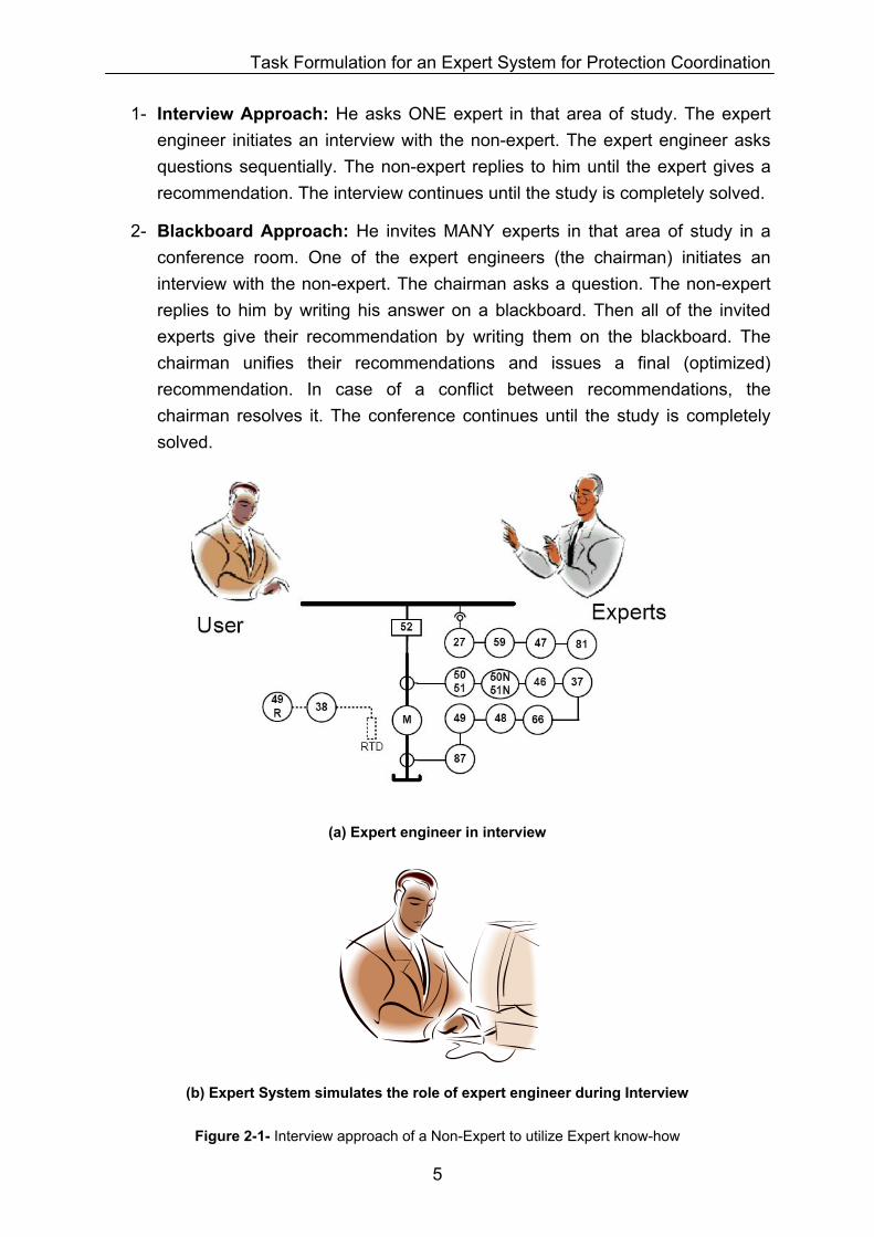
1- Interview Approach: He asks ONE expert in that area of study. The expert engineer initiates an interview with the non-expert. The expert engineer asks questions sequentially. The non-expert replies to him until the expert gives a recommendation. The interview continues until the study is completely solved.
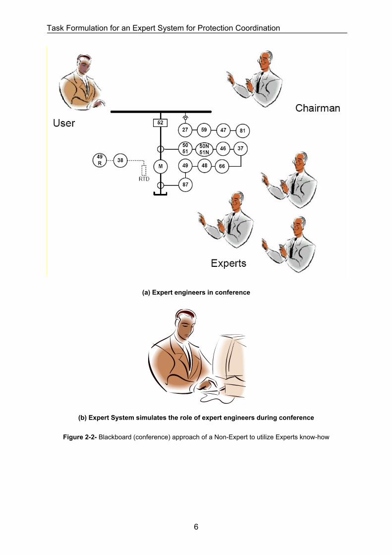
2- Blackboard Approach: He invites MANY experts in that area of study in a conference room. One of the expert engineers (the chairman) initiates an interview with the non-expert. The chairman asks a question. The non-expert replies to him by writing his answer on a blackboard. Then all of the invited experts give their recommendation by writing them on the blackboard. The chairman unifies their recommendations and issues a final (optimized) recommendation. In case of a conflict between recommendations, the chairman resolves it. The conference continues until the study is completely solved.
(a) Expert engineer in interview
(b) Expert System simulates the role of expert engineer during Interview
Figure 2-1- Interview approach of a Non-Expert to utilize Expert know-how
5
Task Formulation for an Expert System for Protection Coordination
(a) Expert engineers in conference
(b) Expert System simulates the role of expert engineers during conference
Figure 2-2- Blackboard (conference) approach of a Non-Expert to utilize Experts know-how
6
Task Formulation for an Expert System for Protection Coordination
22..22 AA RREEVVIIEEWW OONN EEXXPPEERRTT SSYYSSTTEEMMSS
This section gives a review on Expert System principles and features.
22..22..11 DDeeffiinniittiioonn
Expert System is a computer program. This program simulates the consultation behavior of one or more expert engineer(s) during an interview or conference with a non-expert engineer (system user).
An Expert System looks similar to a conventional program. It provides a question with one or more answer option(s). The system user replies to the question. The Expert System responses to the user’s answer by a recommendation or another question that helps solving the study. However, an Expert System is different from a conventional program in the following ways:
1- Expert systems have teaching capability. The system user is considered a non-expert person. But, as a human, he learns the expert knowledge stored in the Expert System by observing the system behavior supported by enough explanations.
2- Expert systems are very interactive programs. They simulate an interview or conference between Expert(s) and non-expert engineer. A conventional program usually issues some error or warning messages during execution.
3- Unlike a conventional program are Expert Systems not restricted to a mathematical model. They can handle heuristic or factual rules.
4- Expert Systems are capable of managing the uncertainty, unreliable or even missing input data or unexpected data by using expert rules.
5- The expert rules are stored in a knowledgebase continuously. The knowledgebase data structure is separated from the problem data structure and from program execution flow. Therefore, the Expert System software does not need to be recompiled by addition of new expert rules. In a conventional program, data structure, problem data and mathematical model are combined together during the program execution. Therefore, any changes in the data structure, mathematical model and the program logic make it necessary for the software to be recompiled and released as a new version.
7
Task Formulation for an Expert System for Protection Coordination
22..22..22 SSttrruuccttuurree
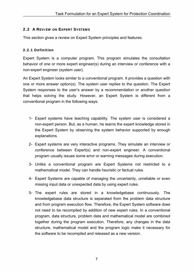
Figure 2-3 shows Expert System components. An expert system has three main parts: a knowledgebase of rules and facts, a context and an inference engine. It has usually three supporting tools: a knowledge acquisition tool, an explanation mechanism and an user interface.
Figure 2-3- Expert System Components ([5] page 31).
The following is a description for each part designated in Figure 2-3.
1- The knowledgebase of rules and facts. The term fact means information that is considered reliable. The knowledgebase contains the facts definition (knowledge representation or problem data structure) and the rules (procedures, strategies, and reasoning that a human expert uses to solve the problem). The rules are the knowledge about using facts information to solve a problem. Rules in the knowledgebase have following format:
Rule x: IF (condition) THEN (action).
The facts structure in the knowledgebase may be represented in the following fashions:
Relational: Data are defined as a list of properties with links to/from other lists.
Hierarchical: Data are defined as objects with properties and methods. Object properties and methods are inherited to each other in a hierarchical tree form (object-oriented).
8
Task Formulation for an Expert System for Protection Coordination
Network:: Data are defined as objects connected together with links presented as a network graph (semantic networks). Each network link (or connection) is directional and says whether the Object A (e.g. unbalance overcurrent protection function) is A-KIND-OF object B (e.g. overcurrent relay) or Object A (e.g. 7SJ64-Function 46) IS-AN-INSTANCE-OF object B (e.g. unbalance overcurrent protection function).
See [7] (chapter 2) for more information.
2- The context (working memory and global database) contains and stores the facts or actual data for the specific problem that should be solved.
3- The inference engine is an inference method capable of using the knowledgebase effectively. It has an interpreter that decides how to apply the rules on the context to infer new knowledge (or a fact) to solve the problem. And it has a scheduler that decides the order in which the rules should be applied. A group of inferences that connect a problem to its solution is called a chain. There are two ways of chaining for the rules that are being analyzed: forward-chaining and backward-chaining.
In forward-chaining, the inference engine starts with facts and matches them to the conditions part of a rule. If the condition is satisfied, the rule's conclusion parts are used to prove additional or further rules. This continues until sufficient rules and facts are established to make a conclusion.
In backward-chaining, the inference engine processes rules by examining first the rule's conclusion part and then its premise. The inference engine selects a rule with a conclusion that directly solves the problem. It then tries to determine whether the rule's premise is true or false. If the premise is false the engine selects another rule. If the premise is neither true nor false (not enough rules or facts have been examined to determine this), the engine selects another rule with a conclusion that could solve the premise.
Forward and backward chaining are efficiently implemented by the Rete pattern matching algorithm [7] (page 530). See also [7] (chapter 3) and [5] (chapter 2) for more information on inference methods.
4- The knowledge acquisition module is the system tool that interfaces with the knowledge engineer or with the human expert, offering resources to add, remove or modify the knowledge represented in the knowledgebase.
9
Task Formulation for an Expert System for Protection Coordination
5- The explanation mechanism is a tracing tool that stores information about how expert systems reach a conclusion i.e. the decisions that are being made by the system during the solution process of a certain problem.
6- The user interface is the component through which the user can communicate with the system. It obtains data and information from the user and supplies results, conclusions, or explanations to the system user on how and why the system reached a certain solution.
22..22..33 GGooaall
It is very difficult to describe in general terms the characteristics that make a problem appropriate for an expert system development. Some aspects that can help to decide to build an expert system are:
1- Expert system development is possible when it can be validated, this means that there are human expert studying the problem, and they agree about their solving methods, the choice and preciseness of the solution.
2- An expert system is justified when human experts are expensive or scarce or there is a great demand of them, when the human expert decision making must take place in a hostile environment, or especially when the knowledge is getting lost, for example, because of the retirement or high rotation of personnel in a company.
3- It is appropriate when it involves heuristic knowledge and the problem can be solved naturally by manipulating symbols and their structures. When the problem can be solved with mathematical models algorithmic methods must be used. Moreover, the problem must be complex or difficult enough to justify the cost and effort of expert system development.
22..22..44 DDeevveellooppmmeenntt
The development of an expert system involves the following phases: knowledge acquisition, formalization, implementation and testing.
Knowledge acquisition involves direct and interactive contact between the human expert and the knowledge engineer. The knowledge engineer takes the expert knowledge, conceptualizes and formalizes it. In this phase one can be faced with the main difficulty in expert system building: expert knowledge acquisition and formalization. Faced with realistic problems to be solved, the human expert has a tendency to show his reasoning and conclusions in a generic way, very far from that
10

Task Formulation for an Expert System for Protection Coordination
necessary for a computer analysis. He combines pieces of his basic knowledge so quickly that it is difficult for him to describe this process in detail.
Knowledge formalization involves expressing concepts and relations in a formal way. There are many techniques that use mechanisms associated to the characteristic of human intelligence to represent the knowledge. They copy the way humans represent their knowledge. These techniques are called formal way or knowledge representation methods and the mostly used ones are: rules, semantic nets and frames. Rules are based on structures like IF(premise) THEN (conclusion) or IF (condition) THEN (action) and they are a natural way to describe dynamic processes; Semantic nets and frames provide a natural way to structure a classification, that is, problems that involve relation/hierarchy.
The implementation phase turns the formalized knowledge into a computer program. In this phase one must use an expert system tool for development, and the choice will depend on the type of problem, knowledge formalization and tool features.
Finally, the testing phase involves the evaluation, revision and validation of the Expert System facing real problems.
22..22..55 TToooollss
Tools for building expert systems are basically software resources that can be divided into these categories: programming languages, system-building aids and knowledge engineering languages.
Program languages used to develop expert systems are generally the languages that have flexibility for the knowledgebase implementation, interface engine construction, and which allow for the development of many interface resources. Some examples are structure-oriented languages such as FORTRAN, PASCAL and C, symbolic-manipulation languages such as LISP and PROLOG, and object oriented languages such as SMALLTALK, DELPHI, and C++.
System building aids are projected mainly to help knowledge acquisition and design. Through the definition of the problem, which involves all possible decisions, its attributes and values, the system will ask the user for examples describing the conditions that led him to this decision. Some of these systems are the RuleMaster, ExpertEase.
Knowledge engineering languages are a set of complete resources used to build expert systems, combining language power with sophisticated interface and support environment. They are commonly called shells. Most of them are based on rules and have their own inference engine. They offer facilities for editing, debugging,
11
Task Formulation for an Expert System for Protection Coordination
executing and interfacing (such as explanation facilities). Some of these shells are CLIPS, JESS, M.4, GURU, G2, and Intellix. (See [5] appendix: AI tools and vendors)
22..22..66 AApppplliiccaattiioonn
Although engineering is an exact science, it is also a knowledge area that involves a lot of intuition and experience. This is naturally clear when we think about the number of experts and consultants necessary to make diagnoses to reach a solution for the majority of problems we encounter.
On the other hand, engineering usually manipulate a great volume of incomplete and/or inaccurate data to see the feasible alternatives for the problem. In these cases a qualitative analysis is frequently more important than a quantitative one.
Above characteristics are favorable for using expert systems as mentioned before.
22..33 EEXXPPEECCTTAATTIIOONNSS FFRROOMM AANN EEXXPPEERRTT SSYYSSTTEEMM FFOORR PPRROOTTEECCTTIIOONN SSYYSSTTEEMM
CCOOOORRDDIINNAATTIIOONN
A protection detailed design usually is the basis for a protection settings study. A protection detailed design is a single line that shows protected equipment, its protection devices, its device functions and their measurement points.
Each protection device has one or more functional module(s); each for a specific protective action. We refer to these modules as device protection function. For example, the protection device 7SJ64 has two phase overcurrent device protection functions: The Function 50 and Function 51.
Device protection function parameters are depending on the manufacturer, device type and device version. In addition to that, they have different measurement quantities and protection methods. Device protection function setting parameters are usually in network secondary value.
12
Task Formulation for an Expert System for Protection Coordination
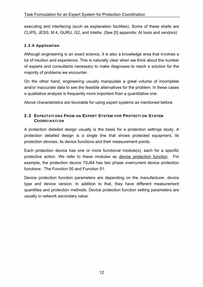
Information on parameters of each protection device is organized in the following table:
Device Protection Function: Name_Type R1_7SJ64
Device Protection Function Parameters
Parameter Name: Primary Value Secondary Value
1202: 50-2 Pickup 6000 A 6.0 A
1203: 50-2 Time delay 0.25 sec 0.25 sec
1204: 50-1 Pickup 1000 A 1.0 A
1205: 50-1 Time delay 1.50 sec 1.5 sec
… … …
Figure 2-4- Organization of a device protection function setting parameters
In section 4.3 we have categorized device protection functions based on the measurement quantities and the protection methods. In addition, we have defined a general protection function for each category and we have assigned general setting parameters to each general protection function.
The general protection function parameters are common among several manufacturers, device types and device versions. General setting parameters are always in network primary value.
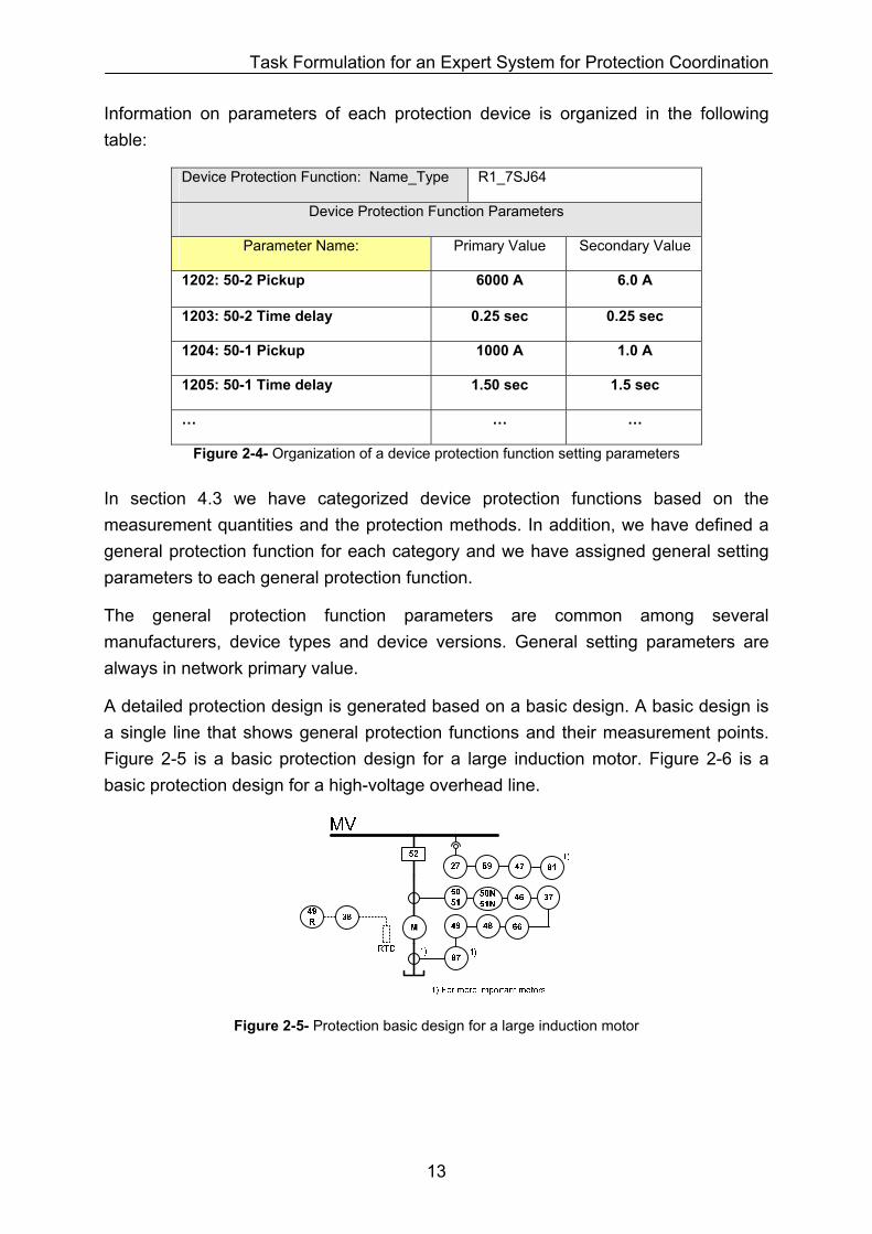
A detailed protection design is generated based on a basic design. A basic design is a single line that shows general protection functions and their measurement points. Figure 2-5 is a basic protection design for a large induction motor. Figure 2-6 is a basic protection design for a high-voltage overhead line.
Figure 2-5- Protection basic design for a large induction motor
13
Task Formulation for an Expert System for Protection Coordination
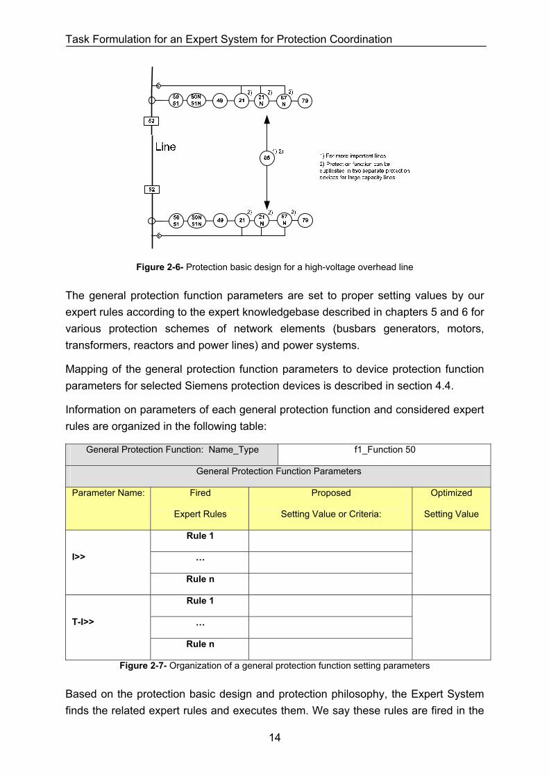
Figure 2-6- Protection basic design for a high-voltage overhead line
The general protection function parameters are set to proper setting values by our expert rules according to the expert knowledgebase described in chapters 5 and 6 for various protection schemes of network elements (busbars generators, motors, transformers, reactors and power lines) and power systems.
Mapping of the general protection function parameters to device protection function parameters for selected Siemens protection devices is described in section 4.4.
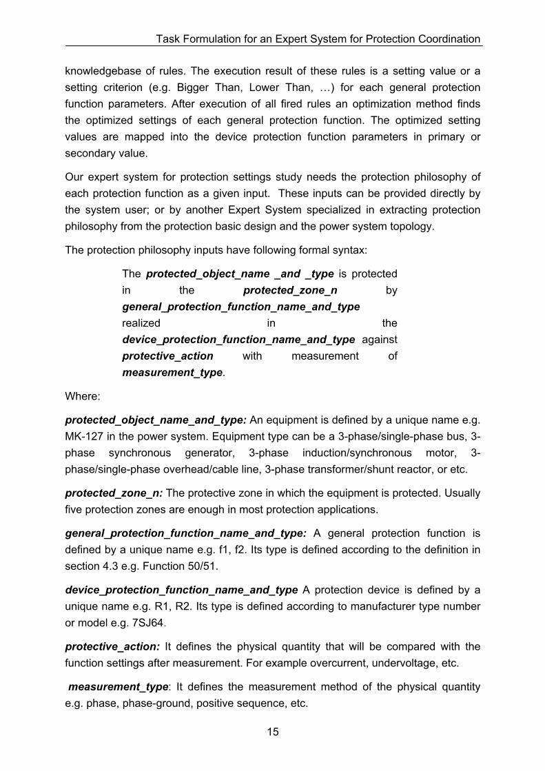
Information on parameters of each general protection function and considered expert rules are organized in the following table:
General Protection Function: Name_Type f1_Function 50
General Protection Function Parameters
Parameter Name: Fired
Expert Rules
Proposed
Setting Value or Criteria:
Optimized
Setting Value
Rule 1
…
I>>
Rule n
Rule 1
…
T-I>>
Rule n
Figure 2-7- Organization of a general protection function setting parameters
Based on the protection basic design and protection philosophy, the Expert System finds the related expert rules and executes them. We say these rules are fired in the
14
Task Formulation for an Expert System for Protection Coordination
knowledgebase of rules. The execution result of these rules is a setting value or a setting criterion (e.g. Bigger Than, Lower Than, …) for each general protection function parameters. After execution of all fired rules an optimization method finds the optimized settings of each general protection function. The optimized setting values are mapped into the device protection function parameters in primary or secondary value.
Our expert system for protection settings study needs the protection philosophy of each protection function as a given input. These inputs can be provided directly by the system user; or by another Expert System specialized in extracting protection philosophy from the protection basic design and the power system topology.
The protection philosophy inputs have following formal syntax:
The protected_object_name _and _type is protected in the protected_zone_n by general_protection_function_name_and_type realized in the device_protection_function_name_and_type against protective_action with measurement of measurement_type.
Where:
protected_object_name_and_type: An equipment is defined by a unique name e.g. MK-127 in the power system. Equipment type can be a 3-phase/single-phase bus, 3-phase synchronous generator, 3-phase induction/synchronous motor, 3-phase/single-phase overhead/cable line, 3-phase transformer/shunt reactor, or etc.
protected_zone_n: The protective zone in which the equipment is protected. Usually five protection zones are enough in most protection applications.
general_protection_function_name_and_type: A general protection function is defined by a unique name e.g. f1, f2. Its type is defined according to the definition in section 4.3 e.g. Function 50/51.
device_protection_function_name_and_type A protection device is defined by a unique name e.g. R1, R2. Its type is defined according to manufacturer type number or model e.g. 7SJ64.
protective_action: It defines the physical quantity that will be compared with the function settings after measurement. For example overcurrent, undervoltage, etc.
measurement_type: It defines the measurement method of the physical quantity e.g. phase, phase-ground, positive sequence, etc.
15
Task Formulation for an Expert System for Protection Coordination
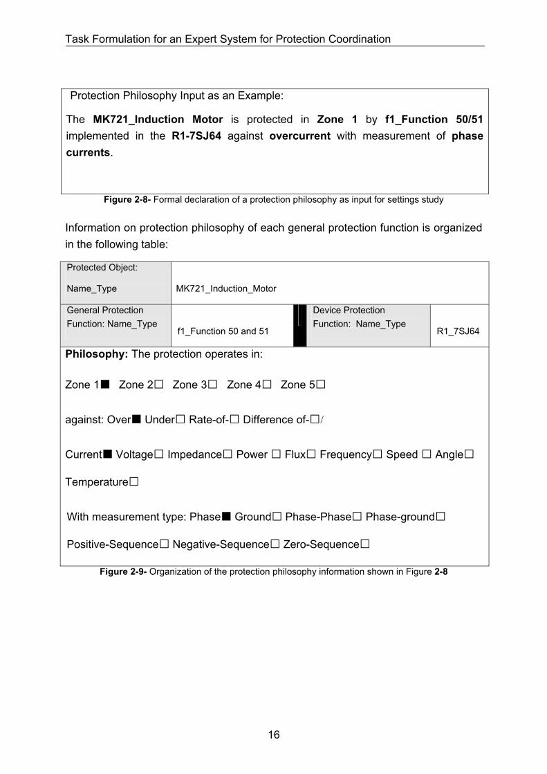
Protection Philosophy Input as an Example:
The MK721_Induction Motor is protected in Zone 1 by f1_Function 50/51 implemented in the R1-7SJ64 against overcurrent with measurement of phase currents.
Figure 2-8- Formal declaration of a protection philosophy as input for settings study
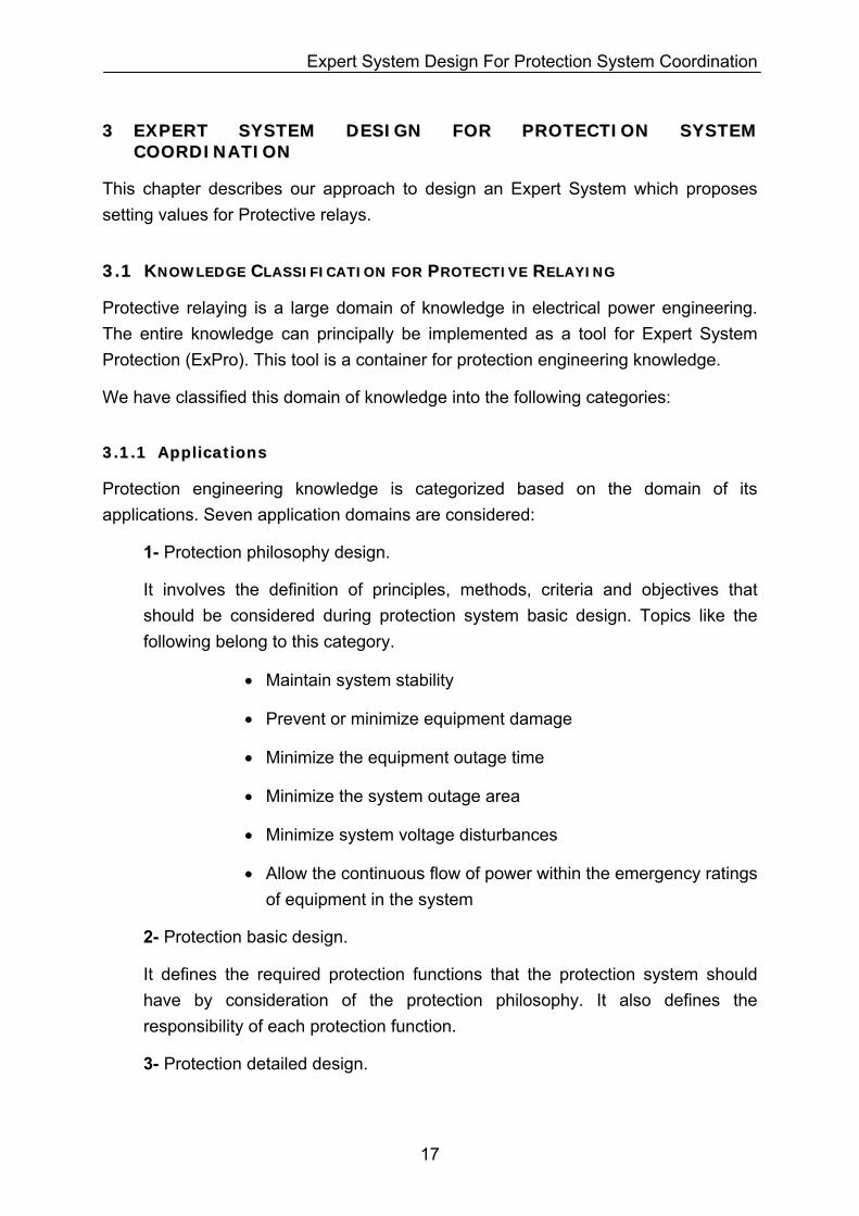
Information on protection philosophy of each general protection function is organized in the following table:
Protected Object:
Name_Type
MK721_Induction_Motor
General Protection Function: Name_Type
f1_Function 50 and 51
Device Protection Function: Name_Type
R1_7SJ64
Philosophy: The protection operates in:
Zone 1 Zone 2 Zone 3 Zone 4 Zone 5
against: Over Under Rate-of- Difference of-/
Current Voltage Impedance Power Flux Frequency Speed Angle
Temperature
With measurement type: Phase Ground Phase-Phase Phase-ground
Positive-Sequence Negative-Sequence Zero-Sequence
Figure 2-9- Organization of the protection philosophy information shown in Figure 2-8
16
Expert System Design For Protection System Coordination
33 EEXXPPEERRTT SSYYSSTTEEMM DDEESSIIGGNN FFOORR PPRROOTTEECCTTIIOONN SSYYSSTTEEMM CCOOOORRDDIINNAATTIIOONN
This chapter describes our approach to design an Expert System which proposes setting values for Protective relays.
33..11 KKNNOOWWLLEEDDGGEE CCLLAASSSSIIFFIICCAATTIIOONN FFOORR PPRROOTTEECCTTIIVVEE RREELLAAYYIINNGG
Protective relaying is a large domain of knowledge in electrical power engineering. The entire knowledge can principally be implemented as a tool for Expert System Protection (ExPro). This tool is a container for protection engineering knowledge.
We have classified this domain of knowledge into the following categories:
33..11..11 AApppplliiccaattiioonnss
Protection engineering knowledge is categorized based on the domain of its applications. Seven application domains are considered:
1- Protection philosophy design.
It involves the definition of principles, methods, criteria and objectives that should be considered during protection system basic design. Topics like the following belong to this category.
• Maintain system stability
• Prevent or minimize equipment damage
• Minimize the equipment outage time
• Minimize the system outage area
• Minimize system voltage disturbances
• Allow the continuous flow of power within the emergency ratings of equipment in the system
2- Protection basic design.
It defines the required protection functions that the protection system should have by consideration of the protection philosophy. It also defines the responsibility of each protection function.
3- Protection detailed design.
17
Expert System Design For Protection System Coordination
It implements the basic design in relays and other protection devices. In addition, it defines the required wiring and signaling.
4- Protection Coordination study.
It defines the protection settings of the protection devices.
5- Protection commissioning.
It implements the protection settings study results into the protection system hardware.
6- Protection test.
It verifies correctness and accuracy of the protection system elements i.e. relays, breakers, CTs, etc. It also verifies the correctness of the protection settings and relay signals connections.
7- Protection maintenance.
It involves a set of recommendations to keep the protection system reliable in operation.
We focus only on the protection coordination study in this dissertation among the domains mentioned above.
33..11..22 AAggeennttss
Agents are specialized expert knowledge in each application. We have considered five agents for protection settings applications.
1- Power plants
2- Transmission networks
3- Industrial plants
4- Distribution networks
5- Electric public transport grids
We extract expert rules from experts in the areas mentioned above.
33..11..33 PPrroocceesssseess
Processes are strategies and sequence of steps that expert engineers conduct to complete a protection settings study. Each agent contains its own processes. For example: to do a protection coordination study in an industrial plan, one can start by finding the protection setting of low voltage motors, then medium voltage motors,
18
Expert System Design For Protection System Coordination
then other terminal loads, etc. Each of these steps is a process for protection settings study.
33..11..44 MMoodduulleess
Modules are a set of knowledge required to adjust all protection functions of a network element or a power system protection concept. Seven modules are considered:
1- Busbar protection
2- Generator protection
3- Motor protection
4- Transformer and reactor protection
5- Line protection
6- System voltage protection
7- System frequency protection
We extract expert rules from experts in the areas mentioned above.
33..11..55 FFrraammeess
Each module is divided into smaller sets called frames. A frame is a set of knowledge required to adjust one protection function of a network element. For example: phase overcurrent protection of a motor, busbar high-impedance differential protection, etc.
33..11..66 SSeessssiioonnss
Each frame contains one or more sets of dialogs with system user in order to get the information from the user and propose a setting value or a criterion for setting value. We call each set of these questions a session.
33..11..77 DDiiaallooggss
A dialog is a question that the system user should reply to. The user can reply to the answer by himself or select the answer from a prepared list of options For example:
What is the motor nominal current? …..
What is the motor type? Synchronous / Asynchronous
19
Expert System Design For Protection System Coordination
20
33..22 EEXXPPEERRTT SSYYSSTTEEMM SSTTRRUUCCTTUURREE
Our expert system implements blackboard (conference) architecture. This architecture considers the execution flow of a protection settings study as a conference between the non-expert person, one expert engineer as the conference chairman and a number of expert engineers invited to the conference. Communication between these three groups is as follows:
1- The chairman (the Expert System program) controls the execution flow of the conference. He asks the non-expert person (the system user) a question and gets his response.
2- The question and the answer are written on a blackboard (the shared system memory).
3- Then each expert engineer (the knowledgebase rules) gives his suggestions or questions to the chairman. The chairman manages them.
4- The expert engineers’ suggestions are written on a blackboard.
5- During the conference execution, the chairman decides at a proper time about the optimized value of a setting parameter with consideration of all expert engineers’ suggestions on that parameter.
6- The conference continues until all setting parameters are set to an optimized value decided by expert engineers and approved by the chairman. In case there is a conflict between expert engineers’ suggestions the chairman resolves it by his judgment.
Our Expert System simulates the architecture mentioned above in a computer program. The system has four major components: The non-expert (or System User), the blackboard (or the Blackboard Repository), the chairman (or the Expert System Chairman Module) and the expert engineers (or the Expert System Knowledgebase Module).
Communication between the system user and the chairman module is carried out by a web-interface. The user observes questions in his browser and replies to them accordingly. The blackboard repository and the chairman module and the knowledgebase module form our Expert System program.
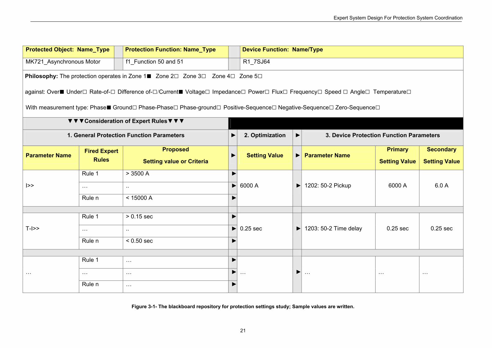
33..22..11 BBllaacckkbbooaarrdd MMoodduullee
It organizes the information of each device protection function (Figure 2-4), corresponding general protection function and optimization results (Figure 2-7) and protection philosophy (Figure 2-9) in one table as follows:
Expert System Design For Protection System Coordination
21
Protected Object: Name_Type Protection Function: Name_Type Device Function: Name/Type
MK721_Asynchronous Motor f1_Function 50 and 51 R1_7SJ64
Philosophy: The protection operates in Zone 1 Zone 2 Zone 3 Zone 4 Zone 5
against: Over Under Rate-of- Difference of-/Current Voltage Impedance Power Flux Frequency Speed Angle Temperature
With measurement type: Phase Ground Phase-Phase Phase-ground Positive-Sequence Negative-Sequence Zero-Sequence
Consideration of Expert Rules
1. General Protection Function Parameters 2. Optimization 3. Device Protection Function Parameters
Parameter Name Fired Expert
Rules
Proposed
Setting value or Criteria Setting Value Parameter Name
Primary
Setting Value
Secondary
Setting Value
Rule 1 > 3500 A
… .. I>>
Rule n < 15000 A
6000 A
1202: 50-2 Pickup
6000 A
6.0 A
Rule 1 > 0.15 sec
… .. T-I>>
Rule n < 0.50 sec
0.25 sec
1203: 50-2 Time delay
0.25 sec
0.25 sec
Rule 1 …
… … …
Rule n …
… … … …
Figure 3-1- The blackboard repository for protection settings study; Sample values are written.
Expert System Design For Protection System Coordination
Chapter 4 explains the parameters that each general protection functions and device protection function requires.
33..22..22 CChhaaiirrmmaann MMoodduullee
Chapter 7 explains the behavior of the chairman module during protection settings study of an example network.
This module is aware of the knowledge classification. It knows in which order of sequence it should ask the system user questions on:
1- Related application.
Example: What is your current task? Protection system setting.
2- Related agent.
Example: In which area is your project? In a transmission network.
3- Related process.
Example: Now adjust LV-motor feeders. Okay.
Example: Now adjust MV-motor feeders. Okay.
4- Related module.
Example: What is your current motor name? MK-127.
5- Related frame.
Each frame corresponds to one table as shown in Figure 3-1. The table is drawn on the blackboard by the chairman. The system user and other experts fill it in based on the network element data, protection philosophy, and optimization methods. Finally the optimized settings are mapped into the device protection function parameters.
The system user answers to a frame question asked by the chairman. The blackboard is partitioned for each protection function. The expert rules in the knowledgebase reply to the facts written in the blackboard repository. Their proposed setting values or criteria for each protection function are written in the devoted partition to that protection function on the blackboard.
6- Related optimization and decision making
In each partition on the blackboard repository (see Figure 3-1), the proposed setting values and criteria are evaluated to propose a final
22
Expert System Design For Protection System Coordination
setting value by the chairman module after all expert rules are considered (or fired) and their results are written on the blackboard.
If the proposed setting values and criteria are not compatible with each other, then the chairman module announces an existence of a conflict. He asks the system user or his own expert rules to suggest a setting value for the conflict situation.
If the proposed setting values and criteria are compatible with each other, then the setting will be optimized to provide shortest fault clearing time or longest operation time based on the fault type and the protection function type.
33..22..33 KKnnoowwlleeddggeebbaassee MMoodduullee
Chapter 5 and 6 explain the expert rules we have collected during this dissertation for protection settings of electrical equipments and power systems. The knowledgebase module suggests a value or a criterion for each general function parameter:
1- Expert knowledgebase contains a set of rules formatted as follows:
IF the fact on the blackboard equals to xxx,
Then initiate a session of question dialogs like xxx .
2- The fact on the blackboard is compared with if-part of each rule in the knowledgebase. Rules with the same if-part as on the blackboard are allowed to execute their then-part sequentially. We say these rules are fired.
3- Each fired rule like an expert engineer asks its questions from the system user as a set of dialog screens.
4- The system user answers to the fired rules leads to a proposed setting values for a protection function parameter, for example:
Curve type = IEC_Normal_Inverse
5- In addition, the answers of the system user can lead to a proposed criteria for a protection function parameters, for example:
Parameter Tp > 0.5 sec
23
Knowledgebase for Protection Functions and Devices
44 KKNNOOWWLLEEDDGGEEBBAASSEE FFOORR PPRROOTTEECCTTIIOONN FFUUNNCCTTIIOONNSS AANNDD DDEEVVIICCEESS
44..11 IINNTTRROODDUUCCTTIIOONN
This chapter describes the device protection functions which are available in protection devices used to protect equipment and system. We also have extended these device protection functions to general protection functions with our assigned setting parameters. The general protection function parameters are set according to the expert rules described in chapters 5 and 6. Then the setting parameters of each general protection function are mapped into its corresponding device protection function which is physically available as hardware with setting parameters.
44..22 PPRROOTTEECCTTIIOONN FFUUNNCCTTIIOONNSS
A protective action in a power system is based on the following four principles:
1- Measurement of physical quantities in the power system. Usually a protection function measures a local quantity like feeder current, bus voltage, etc. A protection function can measure some remote physical quantities like measured current or impedance at the remote end of an overhead line when there is device to device communication. In addition, a protection function can measure several remote quantities like voltage phasor of several busses when there is a wide-area communication between protection devices.
2- Comparison of the measured physical quantities with a setting value or a characteristic. The protection function goes to pickup status if the result of comparison should lead to a protective action. The protection function goes to the reset status if the result of comparison should not lead to a protective action.
3- Logic or decision making based on the status (pickup or reset) of one protection function. A complex decision making based on the status of several protection functions is possible via a logic system between protection devices.
4- Control action which implements a desired protective action like opening a breaker, a fuse blow-out, etc.
Above mentioned functions are implemented in one or a set of protection devices. A protection device like analog and digital relays usually uses secondary techniques; i.e. measurement devices convert the network’s primary physical quantities (current, voltage, power, impedance, …) into secondary values and these values are feed into the relay for comparison, logic and control action. In addition, a protective device like
24
Knowledgebase for Protection Functions and Devices
fuses and sectionalizers use primary techniques; i.e. they have no measurement devices and the comparison, logic and control actions are directly based on network’s primary physical quantities.
Each protection device has one or more functional module(s); each for a specific protective action. We refer to these modules as device protection functions.
IEEE C.37.2-1996 standard [29] defines a standard number for each device protection function based on its measurement quantity and its comparison method. For example, device function number 50 for instantaneous overcurrent and device function number 51 for delayed overcurrent protection. A protection device usually contains one or more device protection functions. For example, the protection device 7SJ64 has three overcurrent stages 50-1, 50-2 and 51-1. Each of these stages is a device protection function.
A device protection function contains a set of setting parameters. In digital relays, each setting parameter is adjusted by an address in the relay long-term memory. In analog and electromechanichal relays, each setting parameter is adjusted by a switch or potentiometer on the relay panel. In fuses the setting parameters are fuse ratings selected by protection designer or equipment manufacturer.
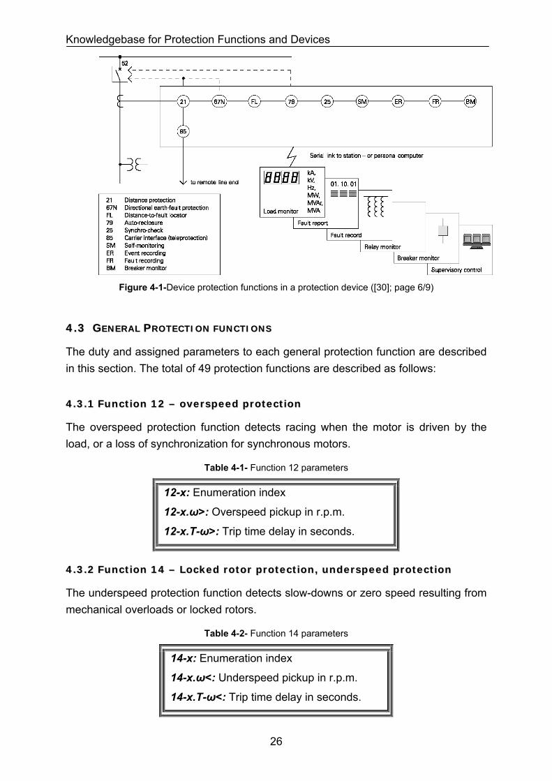
Figure 4-1 shows a typical protection device with several device protection functions. Device protection function parameters are depending on the manufacturer, device type and device version. In addition, they have different measurement quantities and protection methods.
In section 4.3, we have categorized device protection functions based on their measurement quantities and protection methods. In addition, we have defined a general protection function for each category and we have assigned general setting parameters to each general protection function. The general protection function parameters are common among several manufacturers, device types and device versions. General setting parameters are always in primary value.
The general protection function parameters are set to proper setting values by our expert knowledgebase described in chapters 5 and 6 for various protection schemes of network elements (busbars generators, motors, transformers, reactors and power lines) and power systems.
Mapping of the general protection function parameters to device protection function parameters for selected Siemens protection devices are described in section 4.4.
25
Knowledgebase for Protection Functions and Devices
Figure 4-1-Device protection functions in a protection device ([30]; page 6/9)
44..33 GGEENNEERRAALL PPRROOTTEECCTTIIOONN FFUUNNCCTTIIOONNSS
The duty and assigned parameters to each general protection function are described in this section. The total of 49 protection functions are described as follows:
44..33..11 FFuunnccttiioonn 1122 –– oovveerrssppeeeedd pprrootteeccttiioonn
The overspeed protection function detects racing when the motor is driven by the load, or a loss of synchronization for synchronous motors.
Table 4-1- Function 12 parameters
12-x: Enumeration index
12-x.ω>: Overspeed pickup in r.p.m.
12-x.T-ω>: Trip time delay in seconds.
44..33..22 FFuunnccttiioonn 1144 –– LLoocckkeedd rroottoorr pprrootteeccttiioonn,, uunnddeerrssppeeeedd pprrootteeccttiioonn
The underspeed protection function detects slow-downs or zero speed resulting from mechanical overloads or locked rotors.
Table 4-2- Function 14 parameters
14-x: Enumeration index
14-x.ω<: Underspeed pickup in r.p.m.
14-x.T-ω<: Trip time delay in seconds.
26
Knowledgebase for Protection Functions and Devices
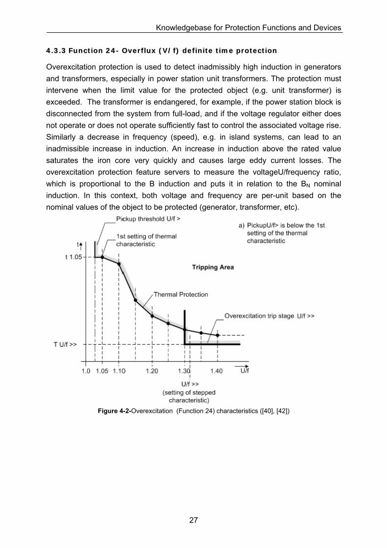
44..33..33 FFuunnccttiioonn 2244-- OOvveerrfflluuxx ((VV//ff)) ddeeffiinniittee ttiimmee pprrootteeccttiioonn
Overexcitation protection is used to detect inadmissibly high induction in generators and transformers, especially in power station unit transformers. The protection must intervene when the limit value for the protected object (e.g. unit transformer) is exceeded. The transformer is endangered, for example, if the power station block is disconnected from the system from full-load, and if the voltage regulator either does not operate or does not operate sufficiently fast to control the associated voltage rise. Similarly a decrease in frequency (speed), e.g. in island systems, can lead to an inadmissible increase in induction. An increase in induction above the rated value saturates the iron core very quickly and causes large eddy current losses. The overexcitation protection feature servers to measure the voltageU/frequency ratio, which is proportional to the B induction and puts it in relation to the BN nominal induction. In this context, both voltage and frequency are per-unit based on the nominal values of the object to be protected (generator, transformer, etc).
Figure 4-2-Overexcitation (Function 24) characteristics ([40], [42])
27
Knowledgebase for Protection Functions and Devices
Table 4-3- Function 24 parameters
24-x: Enumeration index
24-x.v/f>: Overflux definite pickup-1 in percent of machine nominal induction BN.
24-x.T-v/f> : Trip time delay in seconds (Figure 4-2).
24-x.v/f>>: Overflux definite pickup-2 in percent of machine nominal induction BN.
24-x.T-v/f>> : Trip time delay in seconds (Figure 4-2).
24-x.Time for cooling down: This parameter is defined as the time required by the thermal image to cool down from 100 % to 0 % (upto ambient temperature).
24-x.curve point 1. v/f>: Thermal pickup in % of machine nominal induction BN.
24-x.curve point 1.T-v/f> : Trip time delay in seconds (Figure 4-2).
24-x.curve point 2. v/f>: Thermal pickup in % of machine nominal induction BN.
24-x.curve point 2.T-v/f> : Trip time delay in seconds (Figure 4-2).
24-x.curve point 3. v/f>: Thermal pickup in % of machine nominal induction BN.
24-x.curve point 3.T-v/f> : Trip time delay in seconds (Figure 4-2).
24-x.curve point 4. v/f>: Thermal pickup in % of machine nominal induction BN.
24-x.curve point 4.T-v/f> : Trip time delay in seconds (Figure 4-2).
24-x.curve point 5. v/f>: Thermal pickup in % of machine nominal induction BN.
24-x.curve point 5.T-v/f> : Trip time delay in seconds (Figure 4-2).
24-x.curve point 6. v/f>: Thermal pickup in % of machine nominal induction BN.
24-x.curve point 6.T-v/f> :Trip time delay in seconds (Figure 4-2).
24-x.curve point 7. v/f>: Thermal pickup in % of machine nominal induction BN.
24-x.curve point 7.T-v/f> : Trip time delay in seconds (Figure 4-2).
24-x.curve point 8. v/f>: Thermal pickup in % of machine nominal induction BN.
24-x.curve point 8.T-v/f> : Trip time delay in seconds (Figure 4-2).
44..33..44 FFuunnccttiioonn 3377-- UUnnddeerrccuurrrreenntt pprrootteeccttiioonn
When, for example, generators operate in parallel, the active power output of one machine becomes so small that other generators could take over this power, and then it is often appropriate to shut down the lightly loaded machine. The criterion in this case is that the "forwards" current supplied into the network falls below a certain value.
28
Knowledgebase for Protection Functions and Devices
Table 4-4- Function 37 parameters
37-x: Enumeration index
37-x.I<: Undercurrent pickup-1 in r.p.m.
37-x.T-I<: Trip time delay in seconds.
37-x.I<<: Undercurrent pickup-2 in r.p.m.
37-x.T-I<<: Trip time delay in seconds.
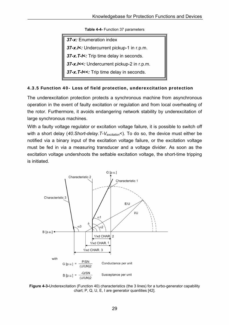
44..33..55 FFuunnccttiioonn 4400-- LLoossss ooff ffiieelldd pprrootteeccttiioonn,, uunnddeerreexxcciittaattiioonn pprrootteeccttiioonn
The underexcitation protection protects a synchronous machine from asynchronous operation in the event of faulty excitation or regulation and from local overheating of the rotor. Furthermore, it avoids endangering network stability by underexcitation of large synchronous machines.
With a faulty voltage regulator or excitation voltage failure, it is possible to switch off with a short delay (40.Short-delay.T-Vexcitation<). To do so, the device must either be notified via a binary input of the excitation voltage failure, or the excitation voltage must be fed in via a measuring transducer and a voltage divider. As soon as the excitation voltage undershoots the settable excitation voltage, the short-time tripping is initiated.
Figure 4-3-Underexcitation (Function 40) characteristics (the 3 lines) for a turbo-generator capability
chart; P, Q, U, E, I are generator quantities [42].
29
Knowledgebase for Protection Functions and Devices
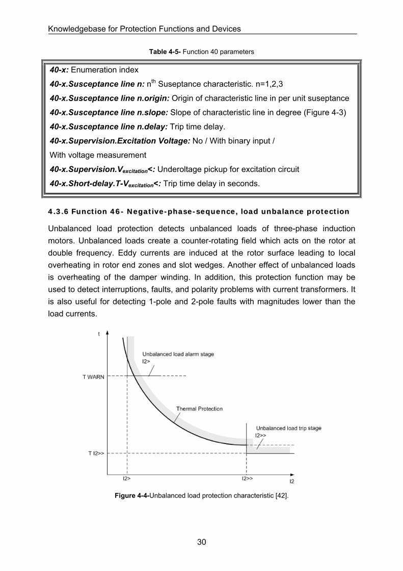
Table 4-5- Function 40 parameters
40-x: Enumeration index
40-x.Susceptance line n: nth Suseptance characteristic. n=1,2,3
40-x.Susceptance line n.origin: Origin of characteristic line in per unit suseptance
40-x.Susceptance line n.slope: Slope of characteristic line in degree (Figure 4-3)
40-x.Susceptance line n.delay: Trip time delay.
40-x.Supervision.Excitation Voltage: No / With binary input /
With voltage measurement
40-x.Supervision.Vexcitation<: Underoltage pickup for excitation circuit
40-x.Short-delay.T-Vexcitation<: Trip time delay in seconds.
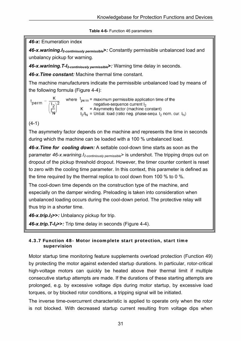
44..33..66 FFuunnccttiioonn 4466-- NNeeggaattiivvee--pphhaassee--sseeqquueennccee,, llooaadd uunnbbaallaannccee pprrootteeccttiioonn
Unbalanced load protection detects unbalanced loads of three-phase induction motors. Unbalanced loads create a counter-rotating field which acts on the rotor at double frequency. Eddy currents are induced at the rotor surface leading to local overheating in rotor end zones and slot wedges. Another effect of unbalanced loads is overheating of the damper winding. In addition, this protection function may be used to detect interruptions, faults, and polarity problems with current transformers. It is also useful for detecting 1-pole and 2-pole faults with magnitudes lower than the load currents.
Figure 4-4-Unbalanced load protection characteristic [42].
30
Knowledgebase for Protection Functions and Devices
Table 4-6- Function 46 parameters
46-x: Enumeration index
46-x.warining.I2-continiously permissible>: Constantly permissible unbalanced load and unbalancy pickup for warning.
46-x.warining.T-I2-continiously permissible>: Warning time delay in seconds.
46-x.Time constant: Machine thermal time constant.
The machine manufacturers indicate the permissible unbalanced load by means of the following formula (Figure 4-4):
(4-1)
The asymmetry factor depends on the machine and represents the time in seconds during which the machine can be loaded with a 100 % unbalanced load.
46-x.Time for cooling down: A settable cool-down time starts as soon as the parameter 46-x.warining.I2-continiously permissible> is undershot. The tripping drops out on dropout of the pickup threshold dropout. However, the timer counter content is reset to zero with the cooling time parameter. In this context, this parameter is defined as the time required by the thermal replica to cool down from 100 % to 0 %.
The cool-down time depends on the construction type of the machine, and especially on the damper winding. Preloading is taken into consideration when unbalanced loading occurs during the cool-down period. The protective relay will thus trip in a shorter time.
46-x.trip.I2>>: Unbalancy pickup for trip.
46-x.trip.T-I2>>: Trip time delay in seconds (Figure 4-4).
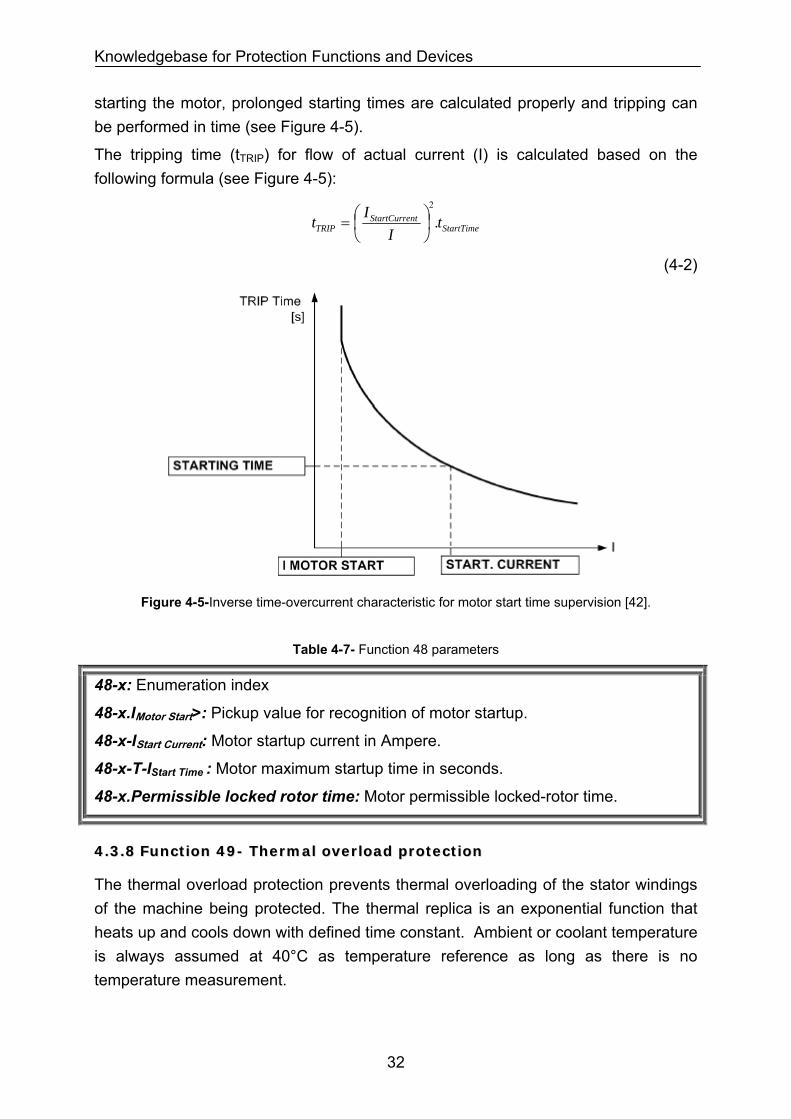
44..33..77 FFuunnccttiioonn 4488-- MMoottoorr iinnccoommpplleettee ssttaarrtt pprrootteeccttiioonn,, ssttaarrtt ttiimmee ssuuppeerrvviissiioonn
Motor startup time monitoring feature supplements overload protection (Function 49) by protecting the motor against extended startup durations. In particular, rotor-critical high-voltage motors can quickly be heated above their thermal limit if multiple consecutive startup attempts are made. If the durations of these starting attempts are prolonged, e.g. by excessive voltage dips during motor startup, by excessive load torques, or by blocked rotor conditions, a tripping signal will be initiated.
The inverse time-overcurrent characteristic is applied to operate only when the rotor is not blocked. With decreased startup current resulting from voltage dips when
31
Knowledgebase for Protection Functions and Devices
starting the motor, prolonged starting times are calculated properly and tripping can be performed in time (see Figure 4-5).
The tripping time (tTRIP) for flow of actual current (I) is calculated based on the following formula (see Figure 4-5):
StartTimentStartCurre
TRIP tI
It .2
⎟⎠⎞
⎜⎝⎛=
(4-2)
Figure 4-5-Inverse time-overcurrent characteristic for motor start time supervision [42].
Table 4-7- Function 48 parameters
48-x: Enumeration index
48-x.IMotor Start>: Pickup value for recognition of motor startup.
48-x-IStart Current: Motor startup current in Ampere.
48-x-T-IStart Time : Motor maximum startup time in seconds.
48-x.Permissible locked rotor time: Motor permissible locked-rotor time.
44..33..88 FFuunnccttiioonn 4499-- TThheerrmmaall oovveerrllooaadd pprrootteeccttiioonn
The thermal overload protection prevents thermal overloading of the stator windings of the machine being protected. The thermal replica is an exponential function that heats up and cools down with defined time constant. Ambient or coolant temperature is always assumed at 40°C as temperature reference as long as there is no temperature measurement.
32
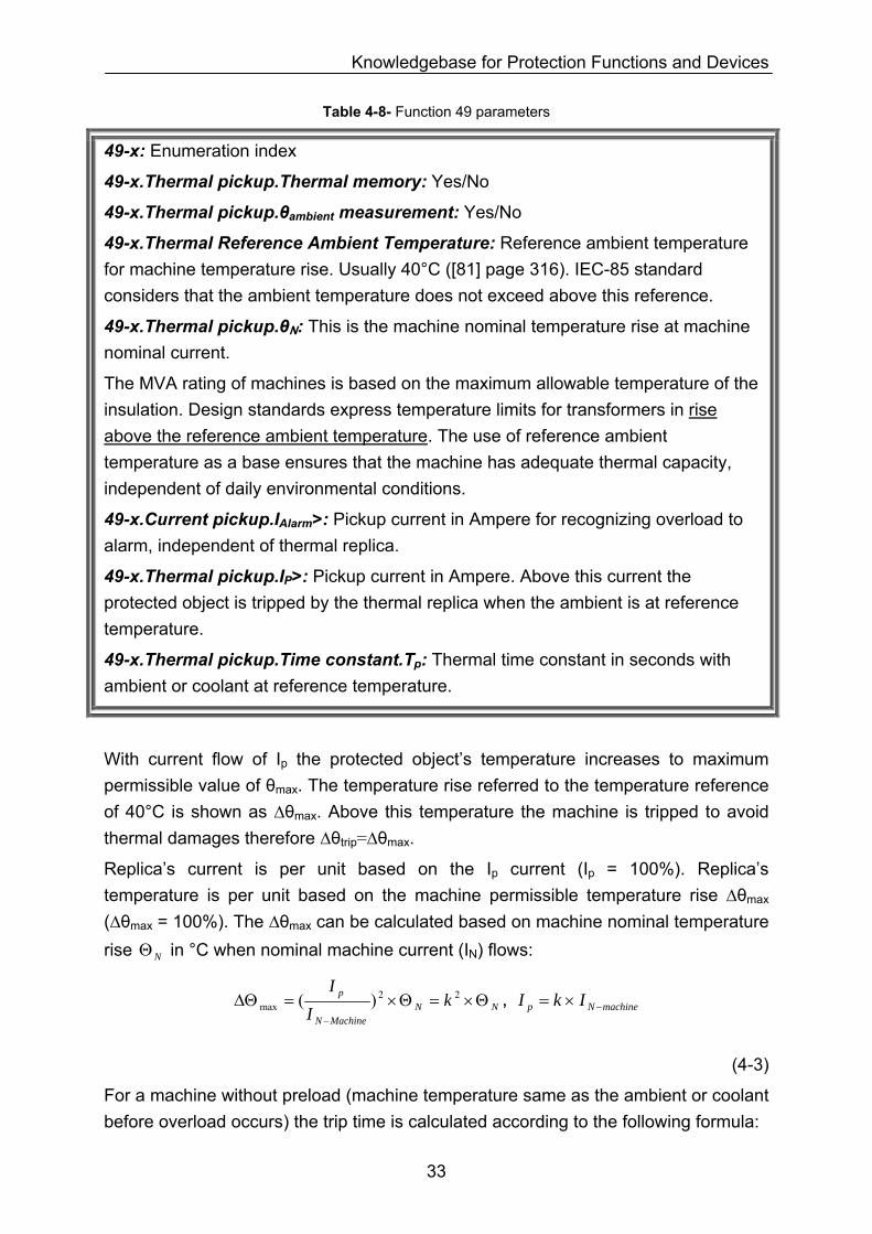
Knowledgebase for Protection Functions and Devices
Table 4-8- Function 49 parameters
49-x: Enumeration index
49-x.Thermal pickup.Thermal memory: Yes/No
49-x.Thermal pickup.θambient measurement: Yes/No
49-x.Thermal Reference Ambient Temperature: Reference ambient temperature for machine temperature rise. Usually 40°C ([81] page 316). IEC-85 standard considers that the ambient temperature does not exceed above this reference.
49-x.Thermal pickup.θN: This is the machine nominal temperature rise at machine nominal current.
The MVA rating of machines is based on the maximum allowable temperature of the insulation. Design standards express temperature limits for transformers in rise above the reference ambient temperature. The use of reference ambient temperature as a base ensures that the machine has adequate thermal capacity, independent of daily environmental conditions.
49-x.Current pickup.IAlarm>: Pickup current in Ampere for recognizing overload to alarm, independent of thermal replica.
49-x.Thermal pickup.IP>: Pickup current in Ampere. Above this current the protected object is tripped by the thermal replica when the ambient is at reference temperature.
49-x.Thermal pickup.Time constant.Tp: Thermal time constant in seconds with ambient or coolant at reference temperature.
With current flow of Ip the protected object’s temperature increases to maximum permissible value of θmax. The temperature rise referred to the temperature reference of 40°C is shown as ∆θmax. Above this temperature the machine is tripped to avoid thermal damages therefore ∆θtrip=∆θmax.
Replica’s current is per unit based on the Ip current (Ip = 100%). Replica’s temperature is per unit based on the machine permissible temperature rise ∆θmax (∆θmax = 100%). The ∆θmax can be calculated based on machine nominal temperature rise in °C when nominal machine current (INΘ N) flows:
NNMachineN
p kI
IΘ×=Θ×=ΔΘ
−
22max )( , machineNp IkI −×=
(4-3)
For a machine without preload (machine temperature same as the ambient or coolant before overload occurs) the trip time is calculated according to the following formula:
33

Knowledgebase for Protection Functions and Devices
maxΔΘ=ΔΘ trip , %100)/( max =ΔΘΔΘtrip => %100)/(
)/(ln. 2
2
−=
p
pPtrip II
IITt
(4-4)
For a machine with preload or thermal memory (machine runs for a while e.g. at and its temperature is higher than the ambient or coolant before
overload occurs) the trip time is calculated according to the following formula: ppreload II ×= %90
maxΔΘ=ΔΘ trip , %100)/( max =ΔΘΔΘtrip , %100)/( ≤ppreload II
=> %100)/(
)/()/(ln. 2
22
−
−=
p
ppreloadpPtrip II
IIIITt , 2
max )/()/( ppreloadpreload II=ΔΘΔΘ
(4-5)
Where is machine maximum permissible temperature rise from 40°C when the
current flows into the object. is machine preload temperature rise before
overload occurs.
maxΔΘ
pI preloadΔΘ
With ambient temperature measurement, the trip time changes when the ambient or coolant temperature deviates from the internal reference temperature of 40 °C.
For a machine with preload and ambient temperature measurement, the trip time is calculated according to the following formula:
maxΔΘ=ΔΘ trip , %100)/( max =ΔΘΔΘtrip , %100)/( ≤Npreload II
=> %100)40()/(
)/()40()/(ln.
max
2
2
max
2
−ΔΘ
°−Θ+
−ΔΘ
°−Θ+
= CII
IICIITt
kp
ppreloadk
p
PTRIP ,
(4-6)
2max )/()/( ppreloadpreload II=ΔΘΔΘ
Where is ambient or coolant temperature in °C, kΘ maxΔΘ is maximum permissible
temperature rise of machine from 40°C when current flows into the object. pI maxΔΘ
is calculated according to the Eq. (4-3).
Table 4-9- Function 49 parameters (continued)
49-x.Thermal pickup.Time constant.Stopped machine extension factor:
Thermal time constant extension factor when machine is stopped.
49-x.Thermal pickup.Maximum current for thermal replica: A pickup value in Ampere that defines the minimum trip time of the replica for higher current than this value regardless of the evaluated temperature. The trip time is the time corresponding to this current value for higher current.
34
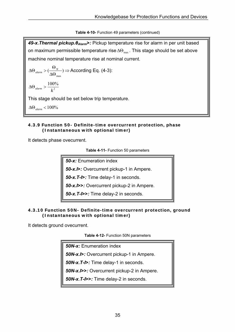
Knowledgebase for Protection Functions and Devices
Table 4-10- Function 49 parameters (continued)
49-x.Thermal pickup.θAlarm>: Pickup temperature rise for alarm in per unit based on maximum permissible temperature rise maxΔΘ . This stage should be set above
machine nominal temperature rise at nominal current.
⇒ΔΘΘ
>ΔΘ )(max
Nalarm According Eq. (4-3):
2
%100kalarm >ΔΘ
This stage should be set below trip temperature.
%100<ΔΘalarm
44..33..99 FFuunnccttiioonn 5500-- DDeeffiinniittee--ttiimmee oovveerrccuurrrreenntt pprrootteeccttiioonn,, pphhaassee ((IInnssttaannttaanneeoouuss wwiitthh ooppttiioonnaall ttiimmeerr))
It detects phase ovecurrent.
Table 4-11- Function 50 parameters
50-x: Enumeration index
50-x.I>: Overcurrent pickup-1 in Ampere.
50-x.T-I>: Time delay-1 in seconds.
50-x.I>>: Overcurrent pickup-2 in Ampere.
50-x.T-I>>: Time delay-2 in seconds.
44..33..1100 FFuunnccttiioonn 5500NN-- DDeeffiinniittee--ttiimmee oovveerrccuurrrreenntt pprrootteeccttiioonn,, ggrroouunndd ((IInnssttaannttaanneeoouuss wwiitthh ooppttiioonnaall ttiimmeerr))
It detects ground ovecurrent.
Table 4-12- Function 50N parameters
50N-x: Enumeration index
50N-x.I>: Overcurrent pickup-1 in Ampere.
50N-x.T-I>: Time delay-1 in seconds.
50N-x.I>>: Overcurrent pickup-2 in Ampere.
50N-x.T-I>>: Time delay-2 in seconds.
35
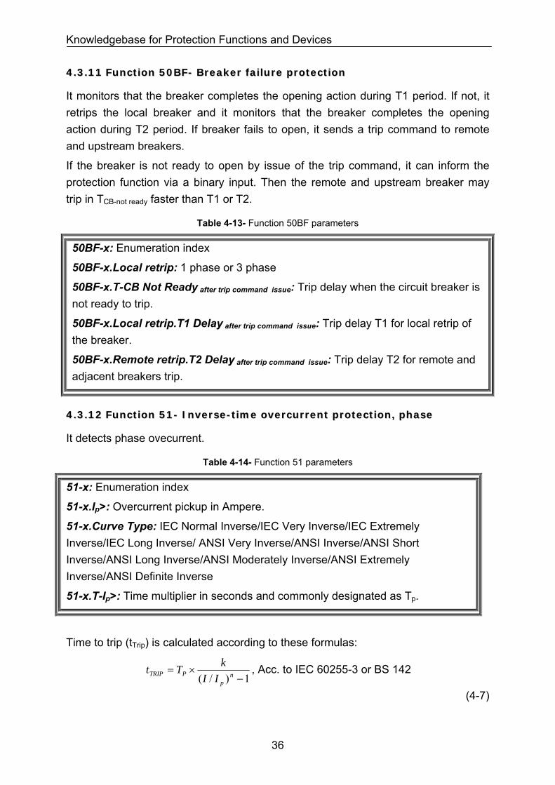
Knowledgebase for Protection Functions and Devices
44..33..1111 FFuunnccttiioonn 5500BBFF-- BBrreeaakkeerr ffaaiilluurree pprrootteeccttiioonn
It monitors that the breaker completes the opening action during T1 period. If not, it retrips the local breaker and it monitors that the breaker completes the opening action during T2 period. If breaker fails to open, it sends a trip command to remote and upstream breakers.
If the breaker is not ready to open by issue of the trip command, it can inform the protection function via a binary input. Then the remote and upstream breaker may trip in TCB-not ready faster than T1 or T2.
Table 4-13- Function 50BF parameters
50BF-x: Enumeration index
50BF-x.Local retrip: 1 phase or 3 phase
50BF-x.T-CB Not Ready after trip command issue: Trip delay when the circuit breaker is not ready to trip.
50BF-x.Local retrip.T1 Delay after trip command issue: Trip delay T1 for local retrip of the breaker.
50BF-x.Remote retrip.T2 Delay after trip command issue: Trip delay T2 for remote and adjacent breakers trip.
44..33..1122 FFuunnccttiioonn 5511-- IInnvveerrssee--ttiimmee oovveerrccuurrrreenntt pprrootteeccttiioonn,, pphhaassee
It detects phase ovecurrent.
Table 4-14- Function 51 parameters
51-x: Enumeration index
51-x.Ip>: Overcurrent pickup in Ampere.
51-x.Curve Type: IEC Normal Inverse/IEC Very Inverse/IEC Extremely Inverse/IEC Long Inverse/ ANSI Very Inverse/ANSI Inverse/ANSI Short Inverse/ANSI Long Inverse/ANSI Moderately Inverse/ANSI Extremely Inverse/ANSI Definite Inverse
51-x.T-Ip>: Time multiplier in seconds and commonly designated as Tp.
Time to trip (tTrip) is calculated according to these formulas:
1)/( −×= n
pPTRIP II
kTt , Acc. to IEC 60255-3 or BS 142
(4-7)
36
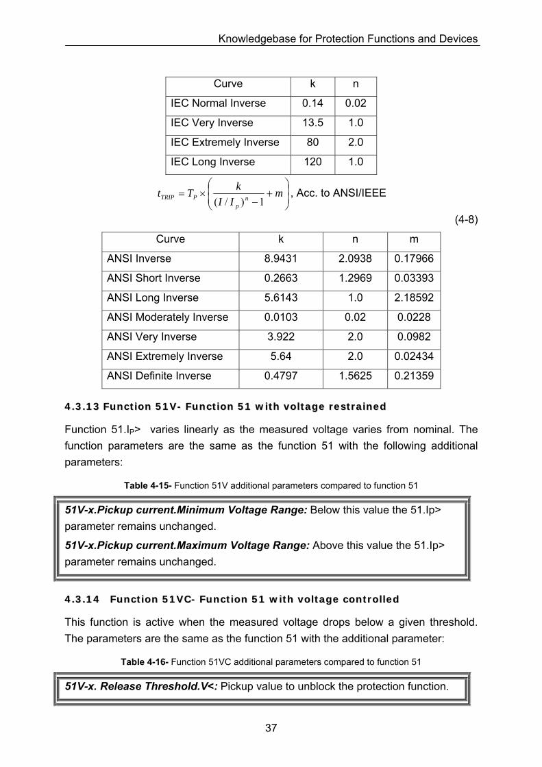
Knowledgebase for Protection Functions and Devices
Curve k n
IEC Normal Inverse 0.14 0.02
IEC Very Inverse 13.5 1.0
IEC Extremely Inverse 80 2.0
IEC Long Inverse 120 1.0
⎟⎟⎠
⎞⎜⎜⎝
⎛+
−×= m
IIkTt np
PTRIP 1)/(, Acc. to ANSI/IEEE
(4-8)
Curve k n m
ANSI Inverse 8.9431 2.0938 0.17966
ANSI Short Inverse 0.2663 1.2969 0.03393
ANSI Long Inverse 5.6143 1.0 2.18592
ANSI Moderately Inverse 0.0103 0.02 0.0228
ANSI Very Inverse 3.922 2.0 0.0982
ANSI Extremely Inverse 5.64 2.0 0.02434
ANSI Definite Inverse 0.4797 1.5625 0.21359
44..33..1133 FFuunnccttiioonn 5511VV-- FFuunnccttiioonn 5511 wwiitthh vvoollttaaggee rreessttrraaiinneedd
Function 51.IP> varies linearly as the measured voltage varies from nominal. The function parameters are the same as the function 51 with the following additional parameters:
Table 4-15- Function 51V additional parameters compared to function 51
51V-x.Pickup current.Minimum Voltage Range: Below this value the 51.Ip> parameter remains unchanged.
51V-x.Pickup current.Maximum Voltage Range: Above this value the 51.Ip> parameter remains unchanged.
44..33..1144 FFuunnccttiioonn 5511VVCC-- FFuunnccttiioonn 5511 wwiitthh vvoollttaaggee ccoonnttrroolllleedd
This function is active when the measured voltage drops below a given threshold. The parameters are the same as the function 51 with the additional parameter:
Table 4-16- Function 51VC additional parameters compared to function 51
51V-x. Release Threshold.V<: Pickup value to unblock the protection function.
37
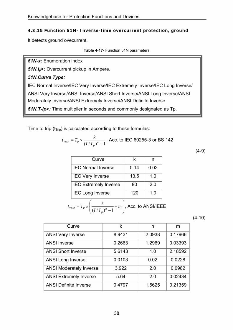
Knowledgebase for Protection Functions and Devices
44..33..1155 FFuunnccttiioonn 5511NN-- IInnvveerrssee--ttiimmee oovveerrccuurrrreenntt pprrootteeccttiioonn,, ggrroouunndd
It detects ground ovecurrent.
Table 4-17- Function 51N parameters
51N-x: Enumeration index
51N.Ip>: Overcurrent pickup in Ampere.
51N.Curve Type:
IEC Normal Inverse/IEC Very Inverse/IEC Extremely Inverse/IEC Long Inverse/
ANSI Very Inverse/ANSI Inverse/ANSI Short Inverse/ANSI Long Inverse/ANSI Moderately Inverse/ANSI Extremely Inverse/ANSI Definite Inverse
51N.T-Ip>: Time multiplier in seconds and commonly designated as Tp.
Time to trip (tTrip) is calculated according to these formulas:
1)/( −
×= np
PTRIP IIkTt , Acc. to IEC 60255-3 or BS 142
(4-9)
Curve k n
IEC Normal Inverse 0.14 0.02
IEC Very Inverse 13.5 1.0
IEC Extremely Inverse 80 2.0
IEC Long Inverse 120 1.0
⎟⎟⎠
⎞⎜⎜⎝
⎛+
−×= m
IIkTt np
PTRIP 1)/(, Acc. to ANSI/IEEE
(4-10)
Curve k n m
ANSI Very Inverse 8.9431 2.0938 0.17966
ANSI Inverse 0.2663 1.2969 0.03393
ANSI Short Inverse 5.6143 1.0 2.18592
ANSI Long Inverse 0.0103 0.02 0.0228
ANSI Moderately Inverse 3.922 2.0 0.0982
ANSI Extremely Inverse 5.64 2.0 0.02434
ANSI Definite Inverse 0.4797 1.5625 0.21359
38
Knowledgebase for Protection Functions and Devices
44..33..1166 FFuunnccttiioonn 6644RR-- RRoottoorr ggrroouunndd ffaauulltt pprrootteeccttiioonn
It measures the rotor insulation resistance to ground by injecting a fundamental frequency sinusoidal voltage [42].
Table 4-18- Function 64R parameters
64R-x: Enumeration index
64R-x.Warning.RE<: Pickup value in ohm to give warning.
64R-x.Warning.T-RE<: Time delay in seconds.
64R-x.Trip.RE<<: Pickup value in ohm to trip.
64R-x.Trip.T-RE<<: Time delay in seconds.
44..33..1177 FFuunnccttiioonn 6644RR ((11--33 HHzz mmeetthhoodd)) -- SSeennssiittiivvee rroottoorr ggrroouunndd ffaauulltt pprrootteeccttiioonn
It measures the rotor insulation resistance to ground by injecting a 1-3 Hz square-wave voltage [42].
Table 4-19- Function 64R (1-3 Hz method) parameters
64R(1-3 Hz method)-x: Enumeration index
64R (1-3 Hz method)-x.Warning.RE<: Pickup value in ohm to give warning.
64R (1-3 Hz method)-x.Warning.T-RE<: Time delay in seconds.
64R (1-3 Hz method)-x.Trip.RE<<: Pickup value in ohm to trip.
64R (1-3 Hz method)-x.Trip.T-RE<<: Time delay in seconds.
44..33..1188 FFuunnccttiioonn 6666//4499RR-- MMoottoorr ssuucccceessssiivvee ssttaarrtt pprrootteeccttiioonn;; rreessttaarrtt iinnhhiibbiitt;; RRoottoorr OOvveerrllooaadd
The rotor temperature of a motor generally remains well below its maximum admissible temperature during normal operation and also under increased load conditions. However, with startups and resulting high startup currents caused by small thermal time constants rotor may suffer more from thermal damage than the stator.
To avoid multiple startup attempts causing motor damage, a repeated startup of the motor must be prevented, if it may be assumed that admissible rotor heating would be exceeded. An inhibit signal is issued until a new motor startup is admissible (restarting threshold). Figure 4-12 shows the rotor temperature and restart inhibit after 3 successive starta of a cold motor (rotor at ambient temperature).
39
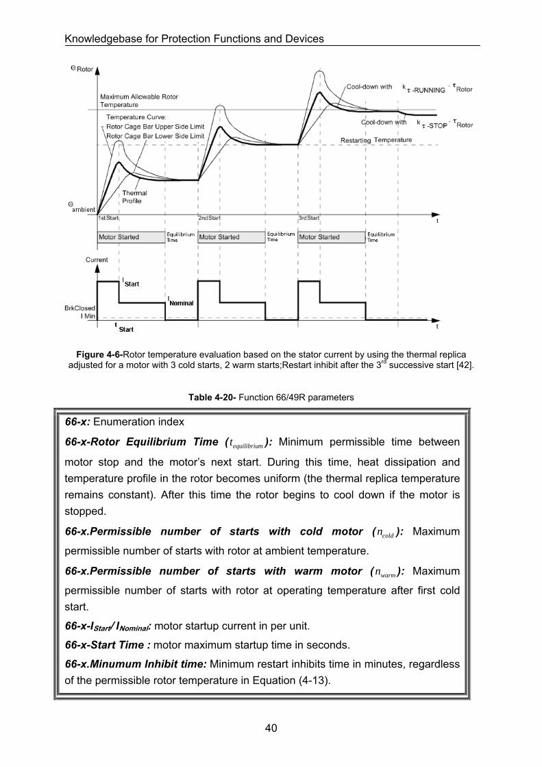
Knowledgebase for Protection Functions and Devices
Figure 4-6-Rotor temperature evaluation based on the stator current by using the thermal replica
adjusted for a motor with 3 cold starts, 2 warm starts;Restart inhibit after the 3rd successive start [42].
Table 4-20- Function 66/49R parameters
66-x: Enumeration index
66-x-Rotor Equilibrium Time ( ): Minimum permissible time between
motor stop and the motor’s next start. During this time, heat dissipation and temperature profile in the rotor becomes uniform (the thermal replica temperature remains constant). After this time the rotor begins to cool down if the motor is stopped.
mequilibriut
66-x.Permissible number of starts with cold motor ( ): Maximum
permissible number of starts with rotor at ambient temperature. coldn
66-x.Permissible number of starts with warm motor ( ): Maximum
permissible number of starts with rotor at operating temperature after first cold start.
warmn
66-x-IStart/ INominal: motor startup current in per unit.
66-x-Start Time : motor maximum startup time in seconds.
66-x.Minumum Inhibit time: Minimum restart inhibits time in minutes, regardless of the permissible rotor temperature in Equation (4-13).
40
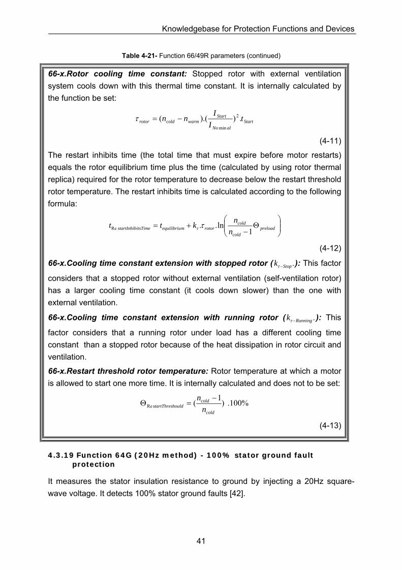
Knowledgebase for Protection Functions and Devices
Table 4-21- Function 66/49R parameters (continued)
66-x.Rotor cooling time constant: Stopped rotor with external ventilation system cools down with this thermal time constant. It is internally calculated by the function be set:
StartalNo
Startwarmcoldrotor t
II
nn .)).(( 2
min
−=τ
(4-11)
The restart inhibits time (the total time that must expire before motor restarts) equals the rotor equilibrium time plus the time (calculated by using rotor thermal replica) required for the rotor temperature to decrease below the restart threshold rotor temperature. The restart inhibits time is calculated according to the following formula:
⎟⎟⎠
⎞⎜⎜⎝
⎛Θ
−+= preload
cold
coldrotormequilibriuitsTimestartInhib n
nktt1
ln..Re ττ
(4-12)
66-x.Cooling time constant extension with stopped rotor ( ): This factor
considers that a stopped rotor without external ventilation (self-ventilation rotor) has a larger cooling time constant (it cools down slower) than the one with external ventilation.
.Stopk −τ
66-x.Cooling time constant extension with running rotor ( ): This
factor considers that a running rotor under load has a different cooling time constant than a stopped rotor because of the heat dissipation in rotor circuit and ventilation.
.Runningk −τ
66-x.Restart threshold rotor temperature: Rotor temperature at which a motor is allowed to start one more time. It is internally calculated and does not to be set:
%100.)1(Recold
coldhouldstartThres n
n −=Θ
(4-13)
44..33..1199 FFuunnccttiioonn 6644GG ((2200HHzz mmeetthhoodd)) -- 110000%% ssttaattoorr ggrroouunndd ffaauulltt pprrootteeccttiioonn
It measures the stator insulation resistance to ground by injecting a 20Hz square-wave voltage. It detects 100% stator ground faults [42].
41
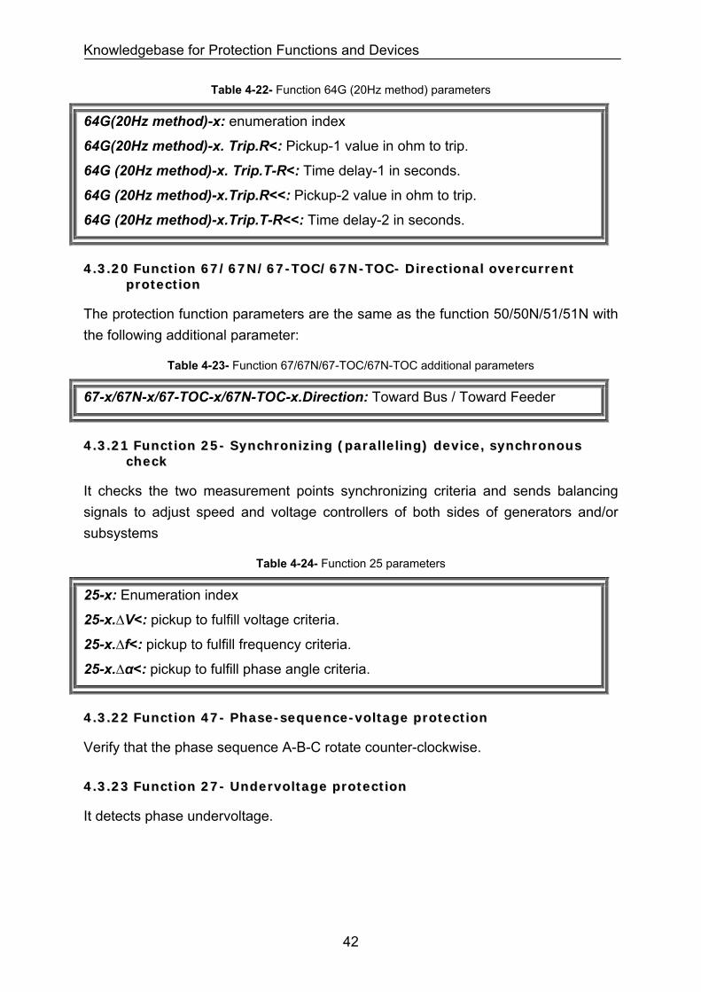
Knowledgebase for Protection Functions and Devices
Table 4-22- Function 64G (20Hz method) parameters
64G(20Hz method)-x: enumeration index
64G(20Hz method)-x. Trip.R<: Pickup-1 value in ohm to trip.
64G (20Hz method)-x. Trip.T-R<: Time delay-1 in seconds.
64G (20Hz method)-x.Trip.R<<: Pickup-2 value in ohm to trip.
64G (20Hz method)-x.Trip.T-R<<: Time delay-2 in seconds.
44..33..2200 FFuunnccttiioonn 6677//6677NN//6677--TTOOCC//6677NN--TTOOCC-- DDiirreeccttiioonnaall oovveerrccuurrrreenntt pprrootteeccttiioonn
The protection function parameters are the same as the function 50/50N/51/51N with the following additional parameter:
Table 4-23- Function 67/67N/67-TOC/67N-TOC additional parameters
67-x/67N-x/67-TOC-x/67N-TOC-x.Direction: Toward Bus / Toward Feeder
44..33..2211 FFuunnccttiioonn 2255-- SSyynncchhrroonniizziinngg ((ppaarraalllleelliinngg)) ddeevviiccee,, ssyynncchhrroonnoouuss cchheecckk
It checks the two measurement points synchronizing criteria and sends balancing signals to adjust speed and voltage controllers of both sides of generators and/or subsystems
Table 4-24- Function 25 parameters
25-x: Enumeration index
25-x.∆V<: pickup to fulfill voltage criteria.
25-x.∆f<: pickup to fulfill frequency criteria.
25-x.∆α<: pickup to fulfill phase angle criteria.
44..33..2222 FFuunnccttiioonn 4477-- PPhhaassee--sseeqquueennccee--vvoollttaaggee pprrootteeccttiioonn
Verify that the phase sequence A-B-C rotate counter-clockwise.
44..33..2233 FFuunnccttiioonn 2277-- UUnnddeerrvvoollttaaggee pprrootteeccttiioonn
It detects phase undervoltage.
42
Knowledgebase for Protection Functions and Devices
Table 4-25- Function 27 parameters
27-x: Enumeration index
27-x.Voltage measurement method: phase-phase/phase-ground
27-x-1.V<: Pickup-1 value in volt.
27-x-1.T-V<: Time delay-1 in seconds.
27-x-2.V<<: Pickup-2 value in volt.
27-x-2.T-V<<: Time delay-2 in seconds.
44..33..2244 FFuunnccttiioonn 5599-- OOvveerrvvoollttaaggee pprrootteeccttiioonn
It detects phase overvoltage.
Table 4-26- Function 59 parameters
59-x: Enumeration index
59-x.Voltage measurement method: phase-phase/phase-ground
59-x.V>: Pickup-1 value in volt.
59-x.T-V>: Time delay-2 in seconds.
59-x.V>>: Pickup-2 value in volt.
59-x.T-V>>: Time delay-2 in seconds.
44..33..2255 FFuunnccttiioonn 5599NN-- RReessiidduuaall vvoollttaaggee ggrroouunndd ffaauulltt pprrootteeccttiioonn
It detects ground overvoltage.
Table 4-27- Function 59N parameters
59N-x: Enumeration index
59N-x.V>: Pickup-1 value in volt.
59N-x.T-V>: Time delay-2 in seconds.
59N-x.V>>: Pickup-2 value in volt.
59N-x.T-V>>: Time delay-2 in seconds.
44..33..2266 FFuunnccttiioonn 5599TTNN//2277((33rdrd hhaarrmmoonniicc mmeetthhoodd)) -- 110000%% SSttaattoorr ggrroouunndd ffaauulltt
It detects 100% stator ground fault by measuring the 3rd harmonic sinusoidal voltage in stator winding [42].
The 3rd harmonic emerges in each machine in a more or less significant way. It is caused by the shape of the poles. If an earth fault occurs in the generator stator
43
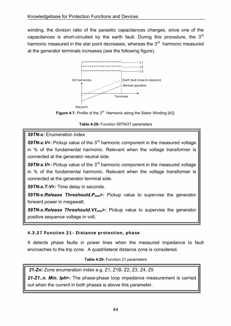
Knowledgebase for Protection Functions and Devices
winding, the division ratio of the parasitic capacitances changes, since one of the capacitances is short-circuited by the earth fault. During this procedure, the 3rd harmonic measured in the star point decreases, whereas the 3rd harmonic measured at the generator terminals increases (see the following figure).
Figure 4-7- Profile of the 3rd Harmonic along the Stator Winding [42].
Table 4-28- Function 59TN/27 parameters
59TN-x: Enumeration index
59TN-x.V<: Pickup value of the 3rd harmonic component in the measured voltage in % of the fundamental harmonic. Relevant when the voltage transformer is connected at the generator neutral side.
59TN-x.V>: Pickup value of the 3rd harmonic component in the measured voltage in % of the fundamental harmonic. Relevant when the voltage transformer is connected at the generator terminal side.
59TN-x.T-V>: Time delay in seconds.
59TN-x.Release Threshould.Pmin>: Pickup value to supervise the generator forward power in megawatt.
59TN-x.Release Threshould.V1min>: Pickup value to supervise the generator positive sequence voltage in volt.
44..33..2277 FFuunnccttiioonn 2211-- DDiissttaannccee pprrootteeccttiioonn,, pphhaassee
It detects phase faults in power lines when the measured impedance to fault encroaches to the trip zone. A quadrilateral distance zone is considered.
Table 4-29- Function 21 parameters
21-Zn: Zone enumeration index e.g. Z1, Z1B, Z2, Z3, Z4, Z5
21-Z1..n. Min. Iph>: The phase-phase loop impedance measurement is carried out when the current in both phases is above this parameter.
44
Knowledgebase for Protection Functions and Devices
Table 4-30- Function 21 parameters (continued)
21-Z1..n.Distance Pickup Method: This parameter defines the pickup method of fault detection module. Three methods are possible: Overcurrent (I>),pickup U/I< Pickup and Impedance Z< Pickup.
21-Z1..n.Distance Pickup value.I> or U/I< or Z<: This parameter defines the pickup value of fault detection module.
21-Z1..n.Distance Pickup.Final Time: This parameter defines the final time delay; after that the function trips if no distance zone trips.
21-Zn.direction<: The distance zone fault detection direction. Forward or reverse or unidirectional.
21-Zn.Xsetting<: Trip zone reactance in ohm.
21-Zn.Rsetting<: Trip zone resistance in ohm.
21-Zn.delay: Trip zone delay time in seconds.
In addition to the value of parameters Xsetting and Rsetting, the ratio Xsetting/Rsetting for the distance protection is important. The Xsetting/Rsetting ratio of zone n should be in the following range so that the function 21 detects reliably a phase to phase fault:
In Zone n: 0.15 < Rsetting/Xsetting < 1.5
(4-14)
In transmission networks, overhead-line towers transport the large part of the delivered energy.
The phase to phase arc resistance is considerable because of the high voltage and spacing between phase conductors.
The arc resistance (Rarc) at the moment of fault inception can be calculated according to the Warington formula ([43], [44] and [46]):
Rarc at fault inception [Ω] = 28700 x Arc Length [m]/ (Arc Current [A]) 1.4
(4-15)
Typical arc resistance at fault inception is between 1.0 to 4.0 ohm for high voltage grids (>132kV). The arc length expands due to wind and its dynamics after fault inception. Following formula estimates the fault resistance with wind velocity ν (typical 3 m/sec) and tB seconds after fault inception:
Rarc after fault inception [Ω] =
(1+ 5 x ν [m/sec]x tB [sec] / Arc Length [m]) x Rarc at fault inception [Ω]
(4-16)
In case of a phase-phase fault in the overhead line, function 21 calculates and observes the following point in the distance polygon:
45
Knowledgebase for Protection Functions and Devices
L = Distance to fault [km]
Rfault = Rline up to the fault location + Rarc at fault inception [Ω] / 2.0
= (0.03 x L+1.5) for a typical line
Xfault = Xline upto the fault location [Ω]
= 0.3 x L for a typical line
Rfault / Xfault = 0.1 + 5.0 / L for a typical line
(4-17)
The distance to fault should be in the following range in order to satisfy the Eq.
(4-14) criteria.
3.5 km < L < 100 km
(4-18)
Based on the criteria above and the criteria in the next section
(4-22), overhead lines can be categorized in three groups:
Normal Overhead Lines: Line length between 10 km to 100 km
Short Overhead Lines: Line length less than 10 km
Long Overhead Lines: Line length over 100 km
(4-19)
Distance protection settings should be categorized
(4-19) based on typical values or , more accurate, based on Eq.
(4-14) , (4-15) and (4-16) criteria.
44..33..2288 FFuunnccttiioonn 2211NN-- DDiissttaannccee pprrootteeccttiioonn,, ggrroouunndd
It detects ground faults in power lines when the measured impedance to fault encroaches to the trip zone. A quadrilateral distance zone is considered.
Table 4-31- Function 21N parameters
21N-Zn: Zone enumeration index e.g. Z1, Z1B, Z2, Z3, Z4, Z5
21N-Z1..n. Min. Iph>: The phase-phase loop impedance measurement is carried out when the current in both phases is above this parameter.
21N-Z1..n. Min. 3I0>: The phase-ground loop impedance measurement is carried out when the zero-sequence current is above this parameter.
21N-Z1..n. Min. 3U0>: The phase-ground loop impedance measurement is carried out when the zero-sequence voltage is above this parameter.
46
Knowledgebase for Protection Functions and Devices
Table 4-32- Function 21N parameters (continued)
21N-Z1..n.Distance Pickup Method: This parameter defines the pickup method of fault detection module. Three methods are: possible Overcurrent (I>),pickup U/I< Pickup and Impedance Z< Pickup.
21N-Z1..n.Distance Pickup value.I> or U/I< or Z<: This parameter defines the pickup value of fault detection module.
21N-Z1..n.Distance Pickup.Final Time: This parameter defines the final time delay; after that the function trips if no distance zone trips.
21N-Zn.direction<: The distance zone fault detection direction. Forward or reverse or unidirectional.
21N-Zn.Xsetting<: Trip zone reactance in ohm.
21N-Zn.Rsetting<: Trip zone resistance in ohm.
21N-Zn.delay: Trip zone delay time in seconds.
In addition to the value of parameters Xsetting and Rsetting, the ratio Xsetting/Rsetting for the distance protection is important. The Xsetting/Rsetting ratio of zone n should be in the following range so that the function 21N detects reliably a phase to ground fault:
In Zone n: 0.45 < Rsetting/Xsetting < 4.5
(4-20)
In transmission networks, overhead-line towers transport the large part of the delivered energy. The phase to ground arc resistance is considerable because of the high voltage and spacing between phase conductors and tower.
The arc resistance (Rarc) at the moment of fault inception can be calculated according to the Warington formula in Eq. (4-15) and Eq. (4-16). Typical arc resistance at fault inception is between 2.0 to 8.0 ohm for high voltage grids (>132kV).
In case of a phase-ground fault, the short-circuit current flows via the arc into the steel armoring of the tower and form there further to the ground. This implies that the arc resistance and tower footing resistance are in series. Typical tower footing resistance is 10 Ohm.
On overhead-lines with ground-wires (shield conductors), the short-circuit current flows into the steel armoring of the tower; then to all adjacent towers via the ground wire. The short-circuit current flows into all adjacent towers and then flows into the ground. Consequently the effective tower footing is reduced because of the parallel current paths to ground ([43], page 145). Typical tower footing resistance is 3 Ohm.
In case of a phase-ground fault in the overhead line, function 21N calculates and observes the following point in the distance polygon:
47
Knowledgebase for Protection Functions and Devices
L = Distance to fault [km]
Xfault = Xline up to the fault location [Ω]
= 0.3 x L for a typical line
Rfault =Rline up to the fault location+ Rarc at fault inception [Ω] + Effective Rtower footing [Ω]
= 0.03 x L+ 8.0 + 3.0
= 0.03 x L+ 11.0
Rfault / Xfault = 0.1 + 36.7 / L for a typical line
(4-21)
The distance to fault should be in the following range in order to satisfy the Eq. (4-20) criteria.
8.3 km < L < 104.8 km
(4-22)
Based on the criteria above and the criteria in the previous section
(4-18), overhead lines can be categorized in three groups:
Short Overhead Lines: Line length less than 10 km
Long Overhead Lines: Line length over 100 km
Normal Overhead Lines: Lines length between 10 km to 100 km
(4-23)
Distance protection settings should be categorized (4-23) based on typical values or , more accurate, based on Eq. (4-20, (4-15) and (4-16) criteria.
44..33..2299 FFuunnccttiioonn 2211FFLL-- FFaauulltt llooccaattoorr
It detects low frequency active power swings in power systems [36].
Table 4-33- Function 21FL parameters
21FL.Line n: Line section enumeration index
21FL-Line n. X per unit length: line section reactance in ohm
44..33..3300 FFuunnccttiioonn 6688-- AAccttiivvee ppoowweerr sswwiinngg ddeetteeccttiioonn
It detects active power swings in power systems [36], [42].
48
Knowledgebase for Protection Functions and Devices
Table 4-34- Function 68 parameters
68-Zn: Zone enumeration index e.g. Z1, Z1B, Z2, Z3, Z4, Z5
68-Zn -Block the distance zones during swing: Yes/No. Block distance zones during power swings.
68-Zn -distance between swing polygon and trip polygon: Impedance margin in ohm that the swing polygon is bigger than the selected distance zone.
68-Zn -Rate of change dZ/dt<: Rate of change of the measured impedance phasor in Ohm/seconds. Power swing angle (δ) and total impedance rate of change (dZ/dt) are related together according to the following formula [42]:
)
2(sin2)(sin2
)()(2
2 δπ
ππ p
p
p fXtf
fXdt
tdRdt
tdZ==≈ in Ω/sec
(4-24)
Where X is the reactance between the sources of power swing, is swing
frequency and δ is swing angle. pf
68-Zn -Action time: Block the distance zone in the given period. It corresponds to minimum frequency of power swing or maximum time that is needed by the impedance trajectory to enter from one side of the swing polygon and trip polygon, then leave from the other side of the trip polygon and swing polygon.
44..33..3311 FFuunnccttiioonn 7788-- OOuutt--ooff--sstteepp pprrootteeccttiioonn;; AAccttiivvee ppoowweerr sswwiinngg ddeetteeccttiioonn wwiitthh mmaaxx.. sswwiinngg aannggllee pprroott..
It detects active power swings in power systems [42].
Table 4-35- Function 78 parameters
78-SwingTripPolygon.X.reverse reach (Zb): Swing detection zone reactance in ohm in reverse direction.
78-SwingTripPolygon.X.forward reach (Zc): Swing detection zone reactance in ohm in forward direction.
78-Number of swings to trip: Permissible number of swings to issue trip.
78-SwingAlarmPolygon.X.forward reach (Zd-Zc): Swing detection zone reactance in ohm in forward direction.
78-Number of swings to warning: Permissible number of swings to issue a warning.
49
Knowledgebase for Protection Functions and Devices
Table 4-36- Function 78 parameters (continued)
78-Angle of polygon inclination: Swing detection zone inclination angle in degree.
78-SwingPolygons.R.reach (Za): Swing detection zone resistance in ohm in forward direction.
Power swing angle (δ) and resistive reach (Za) are related together according to the following formula [42]:
tot
ap Z
Zf ×=
π4 in Ω/sec
(4-25)
Where is the impedance between swing sources and is swing frequency. totZ pf
44..33..3322 FFuunnccttiioonn 8811 UUnnddeerr//OOvveerr ffrreeqquueennccyy pprrootteeccttiioonn
It detects under and over frequencies changes.
Table 4-37- Function 81 parameters
81-x: Enumeration index
81-x.fPickup: Pickup value in Hz.
81-x.T- fPickup: Time delay in seconds.
81-x.fNominal: Nominal frequency in Hz.
81-x.Minimum operating voltage: Pickup in Volt for validity of measurement.
44..33..3333 FFuunnccttiioonn 8811RR-- UUnnddeerr//OOvveerr rraattee--ooff--ffrreeqquueennccyy pprrootteeccttiioonn
It detects under and over Rate-of-Frequencies changes.
Table 4-38- Function 81R parameters
81R-x: Enumeration index
81R-x.df/dt: Pickup value (positive or negative) in Hz/sec.
81R-x.T-df/dt: Time delay in seconds.
81R-x.Measuring window for df/df: Number of cycles for valid measurement.
81R-x.Reset hystersis for df/df: Pickup value (positive or negative) in Hz/sec below this value the function is reset.
81R-x.Minimum operating voltage: Pickup in Volt required for valid measurement.
50
Knowledgebase for Protection Functions and Devices
44..33..3344 FFuunnccttiioonn 3322FF-- FFoorrwwaarrdd ppoowweerr pprrootteeccttiioonn
When, generators operating in parallel, the active power output of one machine becomes so small that other generators could take over this power, then it is often appropriate to shut down the lightly loaded machine. The criterion in this case is that the "forwards" current supplied into the network falls below a certain value.
Table 4-39- Function 32F parameters
32F-x: Enumeration index
32F-x.PForward<: Pickup value in megawatt.
32F-x. T-PForward<: Time delay in seconds.
32F-x.PForward>: Pickup value in megawatt.
32F-x. T-PForward>: Time delay in seconds.
44..33..3355 FFuunnccttiioonn 3322RR-- RReevveerrssee ppoowweerr pprrootteeccttiioonn
Reverse power protection is used to protect a turbo-generator unit from failure of energy to the prime mover when the synchronous generator runs as a motor and drives the turbine taking motoring energy from the network. This condition leads to overheating of the turbine blades and must be interrupted within a short time by tripping the network circuit-breaker. For the generator, there is the additional risk that, in case of a malfunctioning residual steam pass (defective stop valves) after the switching off of the circuit breakers, the turbine-generator-unit is speeded up, thus reaching an overspeed. For this reason, the system isolation should only be performed after the detection of active power input into the machine.
Table 4-40- Function 32R parameters
32R-x: Enumeration index
32R-x.PReverse >: Pickup value in megawatt.
32R-x. Long delay with emergency-stop-valve OPEN status. T- PReverse >: Time delay in seconds.
32R-x.Short delay with emergency-stop-valve CLOSED status. T- PReverse >: Time delay in seconds.
44..33..3366 FFuunnccttiioonn 8877 ((llooww iimmppeeddaannccee))-- PPhhaassee DDiiffffeerreennttiiaall pprrootteeccttiioonn
It detects phase current summation unbalancies in the protection zone. Figure 4-8 shows the principle and characteristic of differential protection.
51
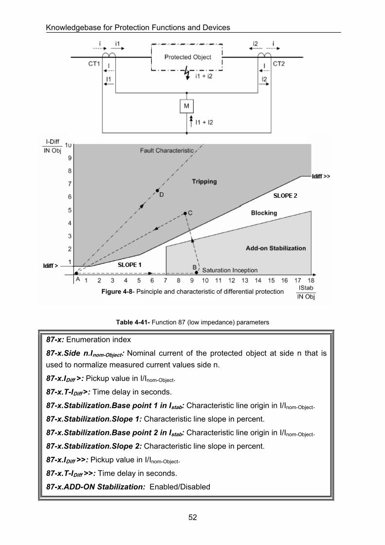
Knowledgebase for Protection Functions and Devices
Figure 4-8- Psinciple and characteristic of differential protection
Table 4-41- Function 87 (low impedance) parameters
87-x: Enumeration index
87-x.Side n.Inom-Object: Nominal current of the protected object at side n that is used to normalize measured current values side n.
87-x.IDiff >: Pickup value in I/Inom-Object.
87-x.T-IDiff >: Time delay in seconds.
87-x.Stabilization.Base point 1 in Istab: Characteristic line origin in I/Inom-Object.
87-x.Stabilization.Slope 1: Characteristic line slope in percent.
87-x.Stabilization.Base point 2 in Istab: Characteristic line origin in I/Inom-Object.
87-x.Stabilization.Slope 2: Characteristic line slope in percent.
87-x.IDiff >>: Pickup value in I/Inom-Object.
87-x.T-IDiff >>: Time delay in seconds.
87-x.ADD-ON Stabilization: Enabled/Disabled
52
Knowledgebase for Protection Functions and Devices
Table 4-42- Function 87 (low impedance) parameters (continued)
87-x.ADD-ON Stabilization.Left boarder.Pickup in Istab:
Pickup value in I/Inom-Object.
87-x.ADD-ON Stabilization.Top boarder.Work with Slope: Slope 1
87-x.ADD-ON Stabilization.Duration in Cycles: Blocking duration in cycles.
87-x.Harmonic Stabilization: Enabled/Disabled
87-x. Harmonic Stabilization.Harmonic n: harmonic number e.g. 2,3,5, …
87-x. Harmonic Stabilization.Harmonic n.Content in IDiff: Pickup value in percent of fundamental frequency content in IDiff >.
87-x. Harmonic Stabilization.Harmonic n.Cross Blocking in Cycles: Number of cycles where all three phases should be blocked when enough harmonic is observed in one phase.
44..33..3377 FFuunnccttiioonn 8866-- LLoocckkoouutt ffuunnccttiioonn
This functions blocks breaker CLOSE commands after the issue and execution of a breaker TRIP command. It waits for a manual reset by a human operator or with an automatic time delay.
Table 4-43- Function 86 parameters
86-x: Enumeration index
86-x.Reset method: Manual / With Time Delay
86-x.Reset delay: defines the time elapse after a breaker TRIP command. Only after this time the breaker can be closed again by automatic control functions.
44..33..3388 FFuunnccttiioonn 8877 ((hhiigghh iimmppeeddaannccee))-- PPhhaassee DDiiffffeerreennttiiaall pprrootteeccttiioonn
It detects phase current summation unbalancies in the protection zone.
Table 4-44- Function 87 (high impedance) parameters
87-x: Enumeration index
87-x.Pickup voltage: Pickup value in volt that leads to trip.
87-x.Pickup current: Pickup value in ampere that leads to trip.
87-x.Shunt Resistor: Shunt resistor value that reduces the protection sensitivity to a desired value.
87-x.Varistor Required: Yes/No. Determines whether a varistor is required.
53
Knowledgebase for Protection Functions and Devices
44..33..3399 FFuunnccttiioonn 8877NN ((llooww iimmppeeddaannccee))-- GGrroouunndd ddiiffffeerreennttiiaall pprrootteeccttiioonn;; RReessttrriicctteedd EEaarrtthh FFaauulltt
It detects ground current summation unbalancies in the protection zone.
Table 4-45- Function 87N (low impedance) parameters
87N-x: Enumeration index
87N-x.IREF >: Pickup value in Ampere.
87N-x.T-IREF >: Time delay in seconds.
87-x.Stabilization.Base point in Istab: Characteristic line origin in I/Inom-Object.
87-x.Stabilization.Slope: Characteristic line slope in degree.
87-x.Block when Iphase current >: Supervising value in Ampere.
87-x.Release when U0>: Supervising value in Volt.
44..33..4400 FFuunnccttiioonn 8877NN ((hhiigghh iimmppeeddaannccee))-- GGrroouunndd ddiiffffeerreennttiiaall pprrootteeccttiioonn;; RReessttrriicctteedd EEaarrtthh FFaauulltt
It detects ground current summation unbalancies in the protection zone.
Table 4-46- Function 87N (high impedance) parameters
87N-x: Enumeration index
87N-x.Pickup voltage: Pickup value in volt that leads to trip.
87N-x.Pickup current: Pickup value in ampere that leads to trip.
87N-x.Shunt Resistor: Shunt resistor value that reduces the protection sensitivity to a desired value.
87N-x.Varistor Required: Yes / No. Determines whether a varistor is required or not.
44..33..4411 FFuunnccttiioonn 7799-- AAuuttoorreecclloossee ffuunnccttiioonn
Experience shows that about 85% of the arc faults on overhead lines are extinguished automatically after being tripped by the protection. This means that the line can be reclosed. Reclosure is performed by an automatic reclosure function (AR). Automatic reclosure is only permitted on overhead lines because the option of automatic extinguishing of a fault arc exists only there. It should not be used in any other case. If the protected object consists of a mixture of overhead lines and other equipment (e.g. overhead line directly connected to a transformer or overhead line/cable), it must be ensured that reclosure can only be performed in the event of a fault on the overhead line.
If the circuit-breaker poles can be operated individually, a single-phase auto-reclosure is usually initiated for single-phase faults, and a three-pole auto-reclosure
54
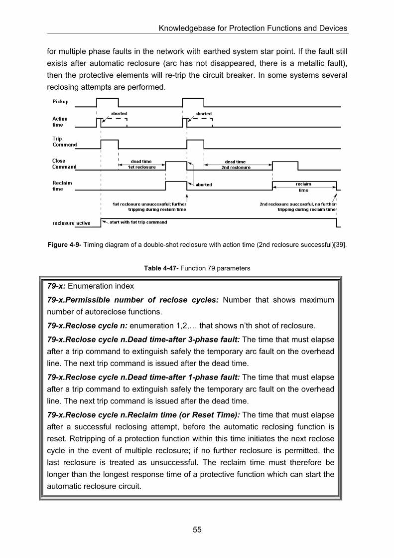
Knowledgebase for Protection Functions and Devices
for multiple phase faults in the network with earthed system star point. If the fault still exists after automatic reclosure (arc has not disappeared, there is a metallic fault), then the protective elements will re-trip the circuit breaker. In some systems several reclosing attempts are performed.
Figure 4-9- Timing diagram of a double-shot reclosure with action time (2nd reclosure successful)[39].
Table 4-47- Function 79 parameters
79-x: Enumeration index
79-x.Permissible number of reclose cycles: Number that shows maximum number of autoreclose functions.
79-x.Reclose cycle n: enumeration 1,2,… that shows n’th shot of reclosure.
79-x.Reclose cycle n.Dead time-after 3-phase fault: The time that must elapse after a trip command to extinguish safely the temporary arc fault on the overhead line. The next trip command is issued after the dead time.
79-x.Reclose cycle n.Dead time-after 1-phase fault: The time that must elapse after a trip command to extinguish safely the temporary arc fault on the overhead line. The next trip command is issued after the dead time.
79-x.Reclose cycle n.Reclaim time (or Reset Time): The time that must elapse after a successful reclosing attempt, before the automatic reclosing function is reset. Retripping of a protection function within this time initiates the next reclose cycle in the event of multiple reclosure; if no further reclosure is permitted, the last reclosure is treated as unsuccessful. The reclaim time must therefore be longer than the longest response time of a protective function which can start the automatic reclosure circuit.
55
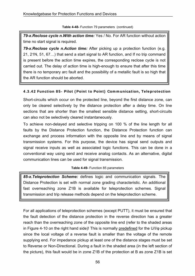
Knowledgebase for Protection Functions and Devices
Table 4-48- Function 79 parameters (continued)
79-x.Reclose cycle n.With action time: Yes / No. For AR function without action time no start signal is required.
79-x.Reclose cycle n.Action time: After picking up a protection function (e.g. 21, 21N, 51, 67…) that send a start signal to AR function, and If no trip command is present before the action time expires, the corresponding reclose cycle is not carried out. The delay of action time is high-enough to ensure that after this time there is no temporary arc fault and the possibility of a metallic fault is so high that the AR function should be aborted.
44..33..4422 FFuunnccttiioonn 8855-- PPiilloott ((PPooiinntt ttoo PPooiinntt)) CCoommmmuunniiccaattiioonn,, TTeelleepprrootteeccttiioonn
Short-circuits which occur on the protected line, beyond the first distance zone, can only be cleared selectively by the distance protection after a delay time. On line sections that are shorter than the smallest sensible distance setting, short-circuits can also not be selectively cleared instantaneously.
To achieve non-delayed and selective tripping on 100 % of the line length for all faults by the Distance Protection function, the Distance Protection function can exchange and process information with the opposite line end by means of signal transmission systems. For this purpose, the device has signal send outputs and signal receive inputs as well as associated logic functions. This can be done in a conventional way using send and receive analog contacts. As an alternative, digital communication lines can be used for signal transmission.
Table 4-49- Function 85 parameters
85-x.Teleprotection Scheme: defines logic and communication signals. The Distance Protection is set with normal zone grading characteristic. An additional fast overreaching zone Z1B is available for teleprotection schemes. Signal transmission and trip release methods depend on the teleprotection scheme.
For all applications of teleprotection schemes (except PUTT), it must be ensured that the fault detection of the distance protection in the reverse direction has a greater reach than the overreaching zone of the opposite line end (refer to the shaded areas in Figure 4-10 on the right hand side)! This is normally predefined for the U/I/φ pickup since the local voltage of a reverse fault is smaller than the voltage of the remote supplying end. For impedance pickup at least one of the distance stages must be set to Reverse or Non-Directional. During a fault in the shaded area (in the left section of the picture), this fault would be in zone Z1B of the protection at B as zone Z1B is set
56
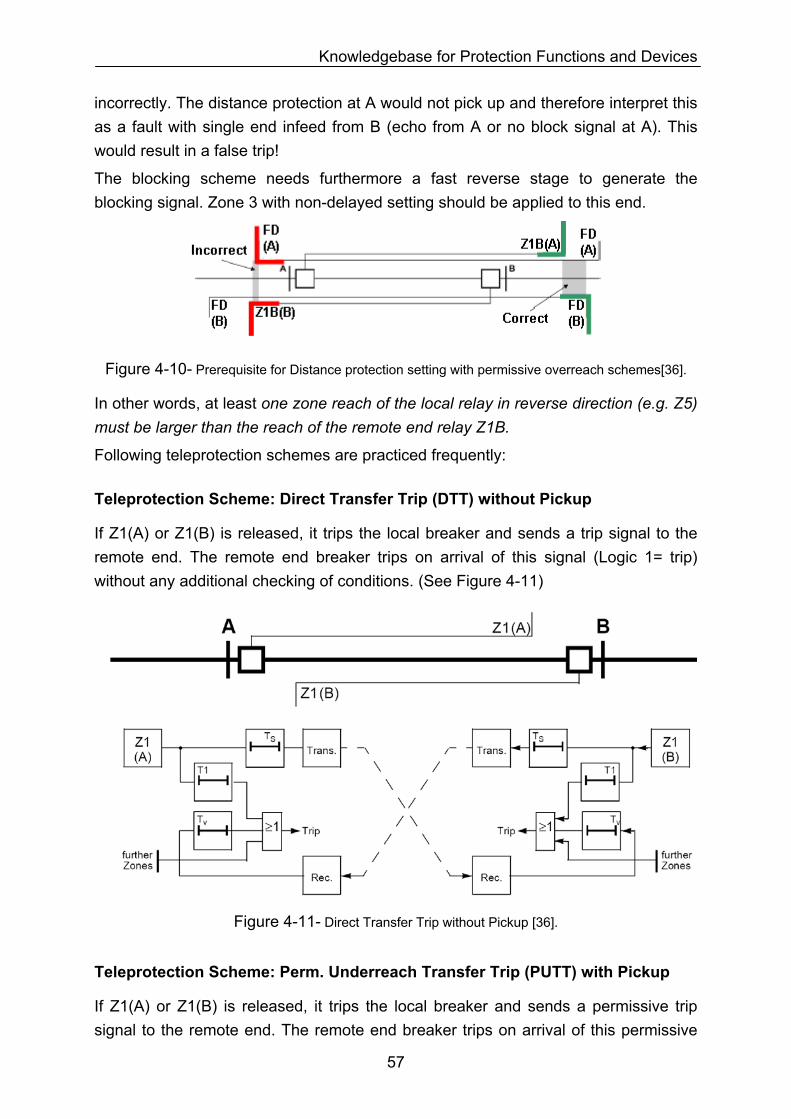
Knowledgebase for Protection Functions and Devices
incorrectly. The distance protection at A would not pick up and therefore interpret this as a fault with single end infeed from B (echo from A or no block signal at A). This would result in a false trip!
The blocking scheme needs furthermore a fast reverse stage to generate the blocking signal. Zone 3 with non-delayed setting should be applied to this end.
Figure 4-10- Prerequisite for Distance protection setting with permissive overreach schemes[36].
In other words, at least one zone reach of the local relay in reverse direction (e.g. Z5) must be larger than the reach of the remote end relay Z1B.
Following teleprotection schemes are practiced frequently:
Teleprotection Scheme: Direct Transfer Trip (DTT) without Pickup
If Z1(A) or Z1(B) is released, it trips the local breaker and sends a trip signal to the remote end. The remote end breaker trips on arrival of this signal (Logic 1= trip) without any additional checking of conditions. (See Figure 4-11)
Figure 4-11- Direct Transfer Trip without Pickup [36].
Teleprotection Scheme: Perm. Underreach Transfer Trip (PUTT) with Pickup
If Z1(A) or Z1(B) is released, it trips the local breaker and sends a permissive trip signal to the remote end. The remote end breaker trips on arrival of this permissive
57
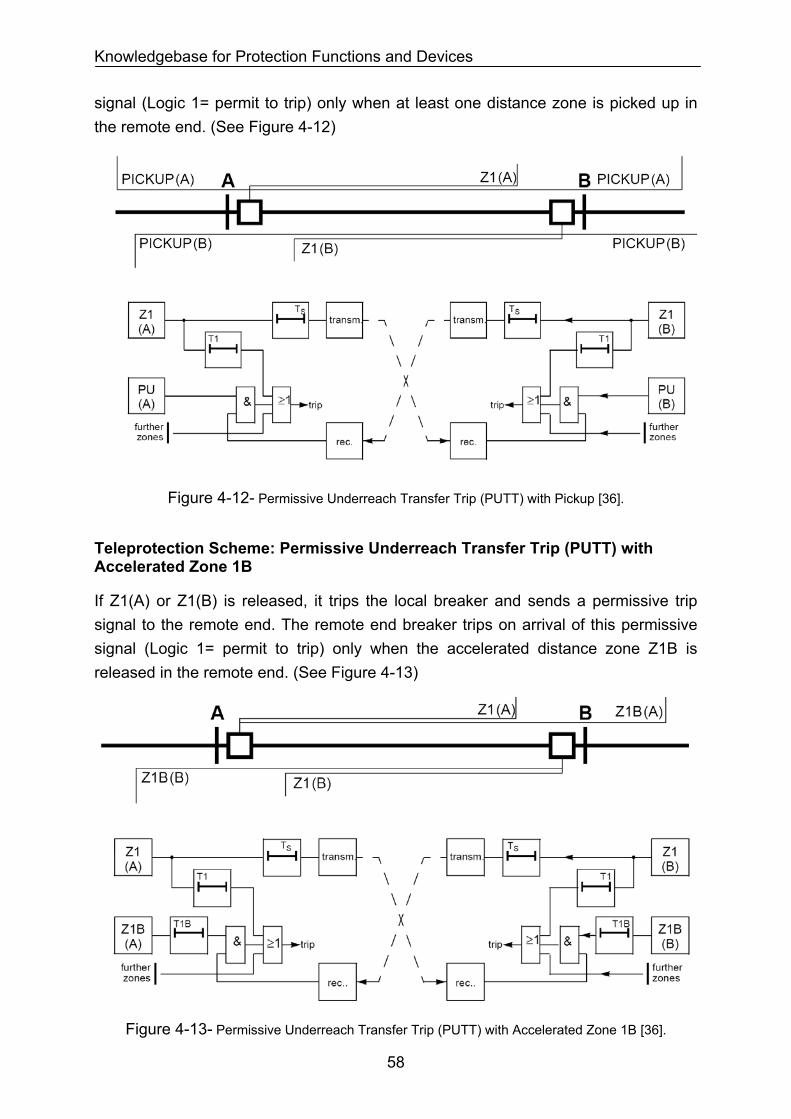
Knowledgebase for Protection Functions and Devices
signal (Logic 1= permit to trip) only when at least one distance zone is picked up in the remote end. (See Figure 4-12)
Figure 4-12- Permissive Underreach Transfer Trip (PUTT) with Pickup [36].
Teleprotection Scheme: Permissive Underreach Transfer Trip (PUTT) with Accelerated Zone 1B
If Z1(A) or Z1(B) is released, it trips the local breaker and sends a permissive trip signal to the remote end. The remote end breaker trips on arrival of this permissive signal (Logic 1= permit to trip) only when the accelerated distance zone Z1B is released in the remote end. (See Figure 4-13)
Figure 4-13- Permissive Underreach Transfer Trip (PUTT) with Accelerated Zone 1B [36].
58
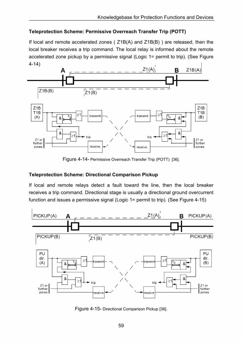
Knowledgebase for Protection Functions and Devices
Teleprotection Scheme: Permissive Overreach Transfer Trip (POTT)
If local and remote accelerated zones ( Z1B(A) and Z1B(B) ) are released, then the local breaker receives a trip command. The local relay is informed about the remote accelerated zone pickup by a permissive signal (Logic 1= permit to trip). (See Figure 4-14)
Figure 4-14- Permissive Overreach Transfer Trip (POTT) [36].
Teleprotection Scheme: Directional Comparison Pickup
If local and remote relays detect a fault toward the line, then the local breaker receives a trip command. Directional stage is usually a directional ground overcurrent function and issues a permissive signal (Logic 1= permit to trip). (See Figure 4-15)
Figure 4-15- Directional Comparison Pickup [36].
59
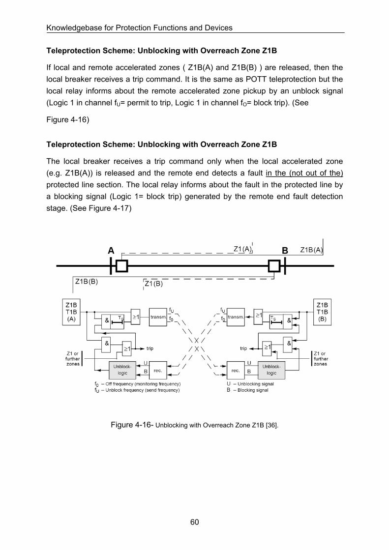
Knowledgebase for Protection Functions and Devices
Teleprotection Scheme: Unblocking with Overreach Zone Z1B
If local and remote accelerated zones ( Z1B(A) and Z1B(B) ) are released, then the local breaker receives a trip command. It is the same as POTT teleprotection but the local relay informs about the remote accelerated zone pickup by an unblock signal (Logic 1 in channel fU= permit to trip, Logic 1 in channel fO= block trip). (See
Figure 4-16)
Teleprotection Scheme: Unblocking with Overreach Zone Z1B
The local breaker receives a trip command only when the local accelerated zone (e.g. Z1B(A)) is released and the remote end detects a fault in the (not out of the) protected line section. The local relay informs about the fault in the protected line by a blocking signal (Logic 1= block trip) generated by the remote end fault detection stage. (See Figure 4-17)
Figure 4-16- Unblocking with Overreach Zone Z1B [36].
60
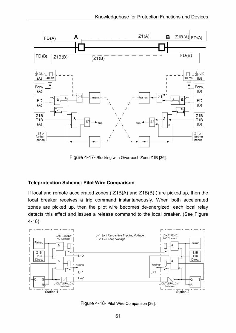
Knowledgebase for Protection Functions and Devices
Figure 4-17- Blocking with Overreach Zone Z1B [36].
Teleprotection Scheme: Pilot Wire Comparison
If local and remote accelerated zones ( Z1B(A) and Z1B(B) ) are picked up, then the local breaker receives a trip command instantaneously. When both accelerated zones are picked up, then the pilot wire becomes de-energized; each local relay detects this effect and issues a release command to the local breaker. (See Figure 4-18)
Figure 4-18- Pilot Wire Comparison [36].
61
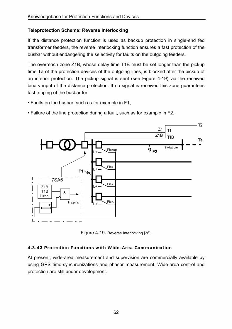
Knowledgebase for Protection Functions and Devices
Teleprotection Scheme: Reverse Interlocking
If the distance protection function is used as backup protection in single-end fed transformer feeders, the reverse interlocking function ensures a fast protection of the busbar without endangering the selectivity for faults on the outgoing feeders.
The overreach zone Z1B, whose delay time T1B must be set longer than the pickup time Ta of the protection devices of the outgoing lines, is blocked after the pickup of an inferior protection. The pickup signal is sent (see Figure 4-19) via the received binary input of the distance protection. If no signal is received this zone guarantees fast tripping of the busbar for:
• Faults on the busbar, such as for example in F1,
• Failure of the line protection during a fault, such as for example in F2.
Figure 4-19- Reverse Interlocking [36].
44..33..4433 PPrrootteeccttiioonn FFuunnccttiioonnss wwiitthh WWiiddee--AArreeaa CCoommmmuunniiccaattiioonn
At present, wide-area measurement and supervision are commercially available by using GPS time-synchronizations and phasor measurement. Wide-area control and protection are still under development.
62
Knowledgebase for Protection Functions and Devices
44..44 DDEEVVIICCEE FFUUNNCCTTIIOONNSS IINN PPRROOTTEECCTTIIOONN DDEEVVIICCEESS
General function parameters should be implemented in one or more device protections by referring to the device manual. More knowledge description on each type of protection device from each manufacturer is avoided in this dissertation.
44..44..11 PPrrootteeccttiioonn DDeevviicceess ooppeerraattiinngg bbyy nneettwwoorrkk sseeccoonnddaarryy qquuaannttiittiieess
Electromechanic Relays
General function parameters should be implemented in relay taps.
Analog Relays
General function parameters should be implemented in relay taps and switches.
Digital Relays
General function parameters should be implemented in relay setting parameters. General function parameters described in section 4.3 can easily be mapped into Siemens relays 7SJ6[31], 7UT6[32], 7SD6[33], 7SS5[34], 7SS6[35], 7SA6[36], 7ST6[37], 7VE6[38], 7VK6[39], 7RW600[40], 7VH60[41], and 7UM6[42]. Similar parameters are available in other relays from other manufacturers.
44..44..22 PPrrootteeccttiioonn DDeevviicceess ooppeerraattiinngg bbyy nneettwwoorrkk pprriimmaarryy qquuaannttiittiieess
General protection parameters are considered in the rated parameter of the device such as fuses, current-limiters and bimetals.
63
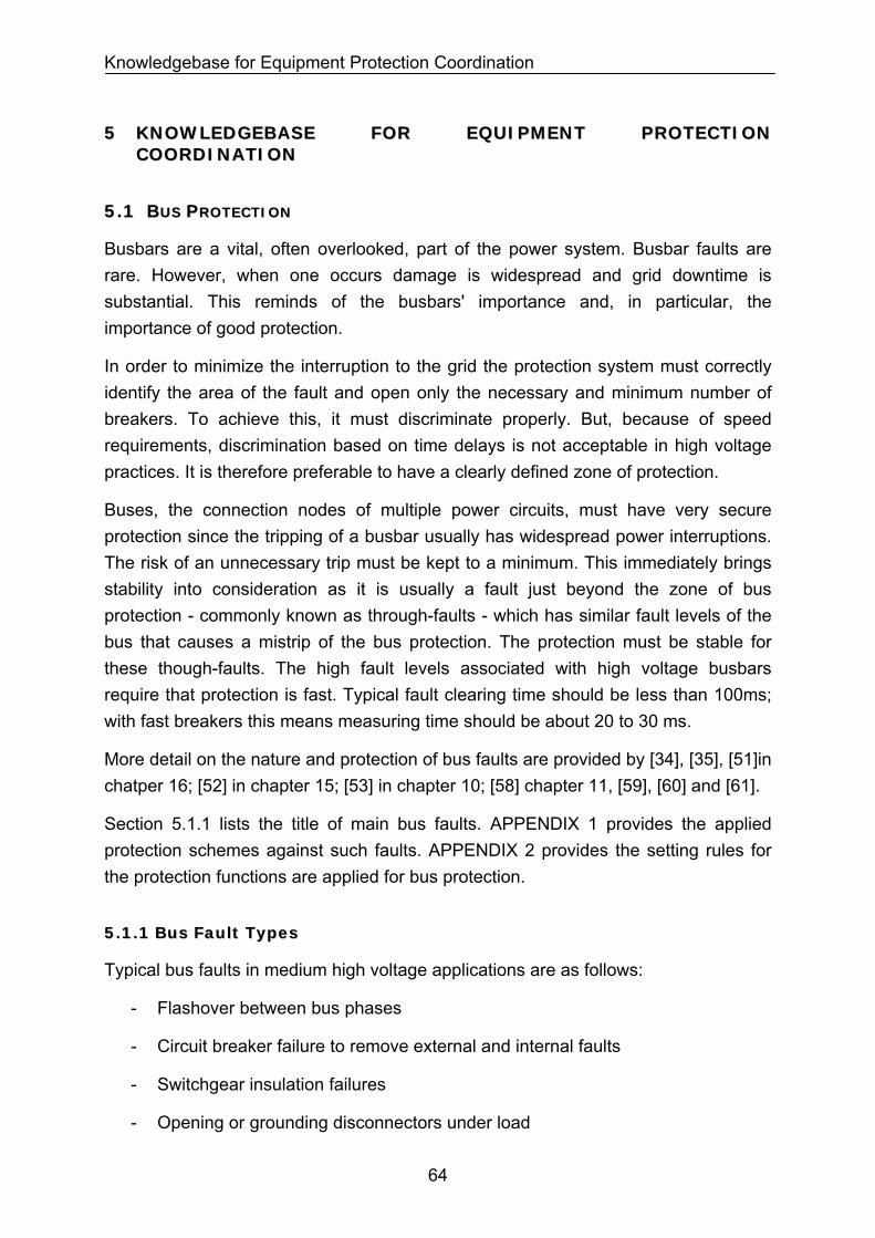
Knowledgebase for Equipment Protection Coordination
55 KKNNOOWWLLEEDDGGEEBBAASSEE FFOORR EEQQUUIIPPMMEENNTT PPRROOTTEECCTTIIOONN CCOOOORRDDIINNAATTIIOONN
55..11 BBUUSS PPRROOTTEECCTTIIOONN
Busbars are a vital, often overlooked, part of the power system. Busbar faults are rare. However, when one occurs damage is widespread and grid downtime is substantial. This reminds of the busbars' importance and, in particular, the importance of good protection.
In order to minimize the interruption to the grid the protection system must correctly identify the area of the fault and open only the necessary and minimum number of breakers. To achieve this, it must discriminate properly. But, because of speed requirements, discrimination based on time delays is not acceptable in high voltage practices. It is therefore preferable to have a clearly defined zone of protection.
Buses, the connection nodes of multiple power circuits, must have very secure protection since the tripping of a busbar usually has widespread power interruptions. The risk of an unnecessary trip must be kept to a minimum. This immediately brings stability into consideration as it is usually a fault just beyond the zone of bus protection - commonly known as through-faults - which has similar fault levels of the bus that causes a mistrip of the bus protection. The protection must be stable for these though-faults. The high fault levels associated with high voltage busbars require that protection is fast. Typical fault clearing time should be less than 100ms; with fast breakers this means measuring time should be about 20 to 30 ms.
More detail on the nature and protection of bus faults are provided by [34], [35], [51]in chatper 16; [52] in chapter 15; [53] in chapter 10; [58] chapter 11, [59], [60] and [61].
Section 5.1.1 lists the title of main bus faults. APPENDIX 1 provides the applied protection schemes against such faults. APPENDIX 2 provides the setting rules for the protection functions are applied for bus protection.
55..11..11 BBuuss FFaauulltt TTyyppeess
Typical bus faults in medium high voltage applications are as follows:
- Flashover between bus phases
- Circuit breaker failure to remove external and internal faults
- Switchgear insulation failures
- Opening or grounding disconnectors under load
64
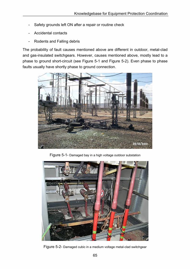
Knowledgebase for Equipment Protection Coordination
- Safety grounds left ON after a repair or routine check
- Accidental contacts
- Rodents and Falling debris
The probability of fault causes mentioned above are different in outdoor, metal-clad and gas-insulated switchgears. However, causes mentioned above, mostly lead to a phase to ground short-circuit (see Figure 5-1 and Figure 5-2). Even phase to phase faults usually have shortly phase to ground connection.
Figure 5-1- Damaged bay in a high voltage outdoor substation
Figure 5-2- Damaged cubic in a medium voltage metal-clad switchgear
65
Knowledgebase for Equipment Protection Coordination
5.1.1.1 Phase to Ground Faults
In grounded networks, a phase to ground short-circuit usually leads to a permanent damage, at least at the bay/cubic where the fault occurs. Additionally, it applies large thermal and mechanical stress on the ground system.
In ungrounded networks, a phase to ground fault at one phase increases the potential of other phases to ground by 170%.
5.1.1.2 Phase to Phase Faults
In grounded and ungrounded networks, a phase to phase short-circuit usually leads to a permanent damage at least at the bay/cubic where the fault occurs. Additionally, it creates a large unbalancy in network voltages and currents. This can affect other equipment connected to bus like generators, motors, transformers down stream loads, etc.
The bus protection schemes are represented in APPENDIX 1. APPENDIX 2 provides the setting rules for the protection functions applied for bus protection.
55..22 GGEENNEERRAATTOORR PPRROOTTEECCTTIIOONN
Details on the nature and protection of generator faults are provided by [42]; [51] in chapter 18; [52] in chapter 17; [53] in chapter 8; and [60].
Section 5.2.1 lists the main generator faults. APPENDIX 3 provides the applied protection schemes against such faults. APPENDIX 4 provides the setting rules for the protection functions applied for generator protection.
66
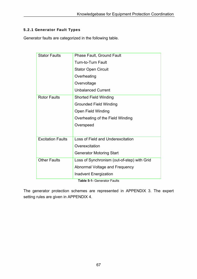
Knowledgebase for Equipment Protection Coordination
55..22..11 GGeenneerraattoorr FFaauulltt TTyyppeess
Generator faults are categorized in the following table.
Stator Faults
Phase Fault, Ground Fault
Turn-to-Turn Fault
Stator Open Circuit
Overheating
Overvoltage
Unbalanced Current
Rotor Faults Shorted Field Winding
Grounded Field Winding
Open Field Winding
Overheating of the Field Winding
Overspeed
Excitation Faults
Loss of Field and Underexcitation
Overexcitation
Generator Motoring Start
Loss of Synchronism (out-of-step) with Grid Other Faults
Abnormal Voltage and Frequency Inadvent Energization
Table 5-1- Generator Faults
The generator protection schemes are represented in APPENDIX 3. The expert setting rules are given in APPENDIX 4.
67
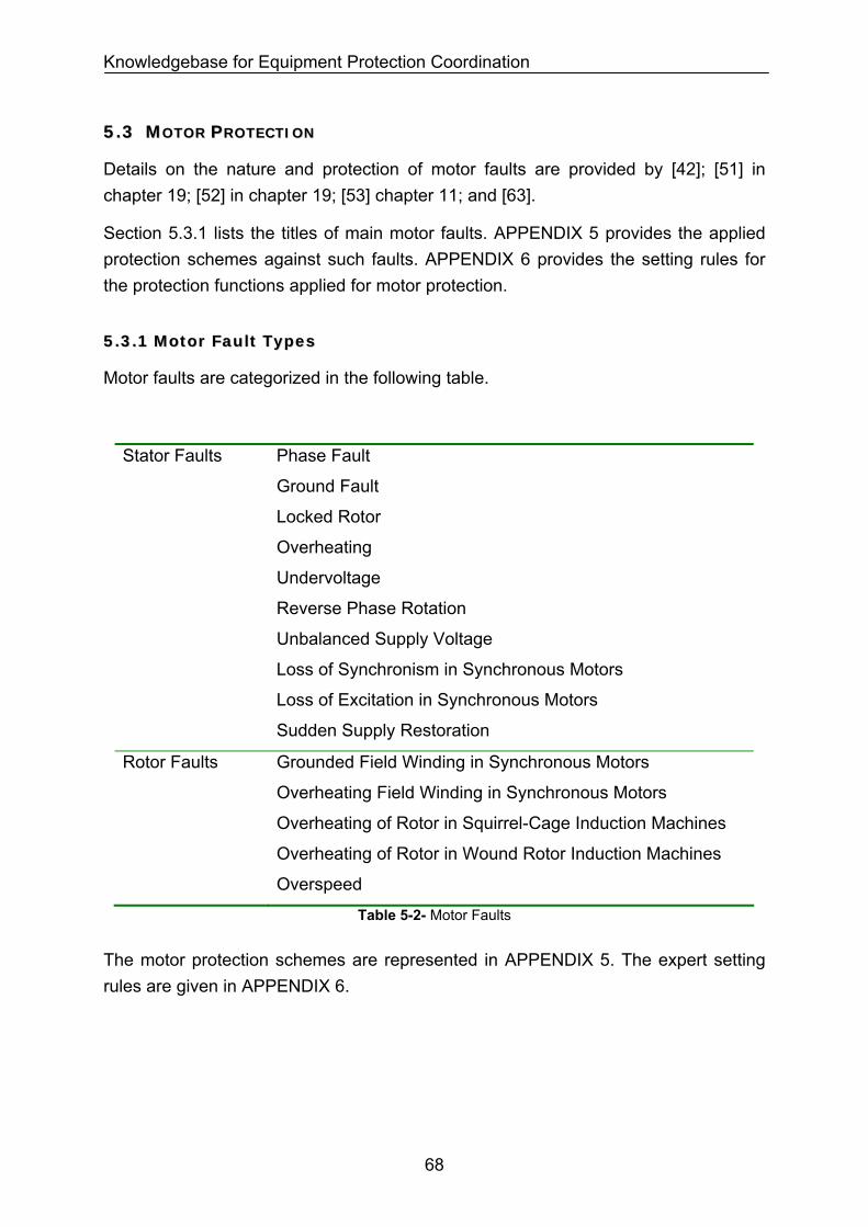
Knowledgebase for Equipment Protection Coordination
55..33 MMOOTTOORR PPRROOTTEECCTTIIOONN
Details on the nature and protection of motor faults are provided by [42]; [51] in chapter 19; [52] in chapter 19; [53] chapter 11; and [63].
Section 5.3.1 lists the titles of main motor faults. APPENDIX 5 provides the applied protection schemes against such faults. APPENDIX 6 provides the setting rules for the protection functions applied for motor protection.
55..33..11 MMoottoorr FFaauulltt TTyyppeess
Motor faults are categorized in the following table.
Stator Faults
Phase Fault
Ground Fault
Locked Rotor
Overheating
Undervoltage
Reverse Phase Rotation
Unbalanced Supply Voltage
Loss of Synchronism in Synchronous Motors
Loss of Excitation in Synchronous Motors
Sudden Supply Restoration
Rotor Faults Grounded Field Winding in Synchronous Motors
Overheating Field Winding in Synchronous Motors
Overheating of Rotor in Squirrel-Cage Induction Machines
Overheating of Rotor in Wound Rotor Induction Machines
Overspeed
Table 5-2- Motor Faults
The motor protection schemes are represented in APPENDIX 5. The expert setting rules are given in APPENDIX 6.
68
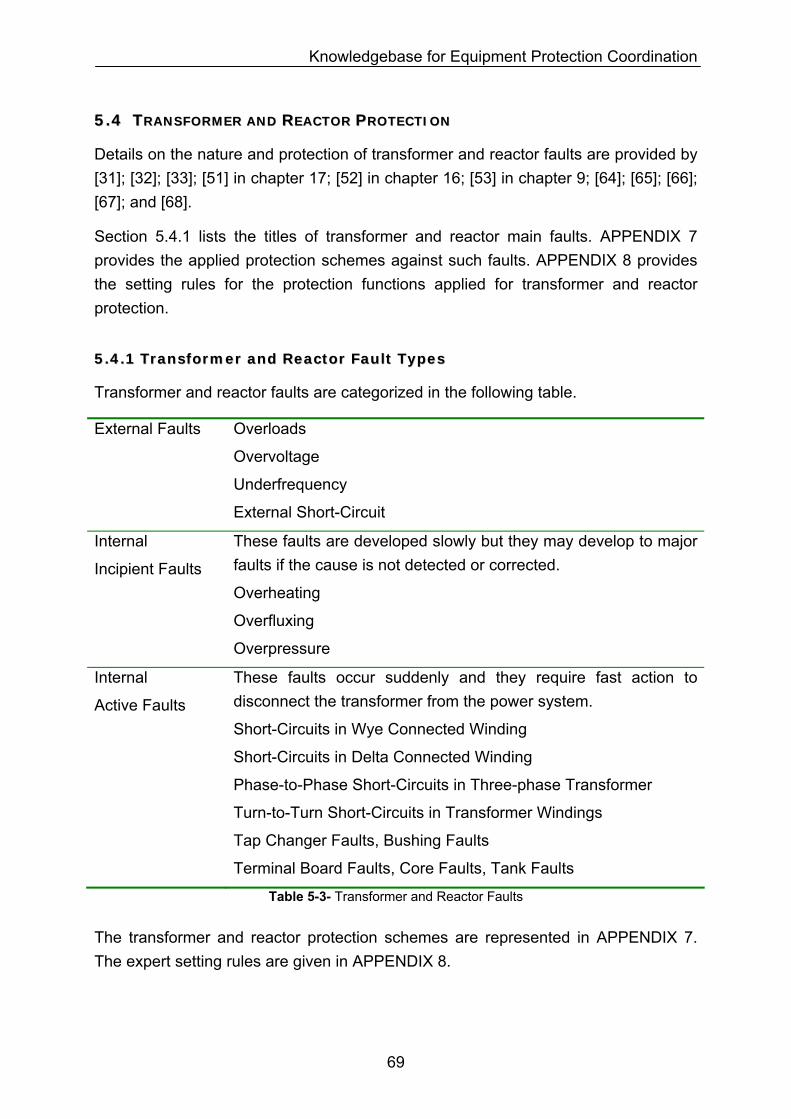
Knowledgebase for Equipment Protection Coordination
55..44 TTRRAANNSSFFOORRMMEERR AANNDD RREEAACCTTOORR PPRROOTTEECCTTIIOONN
Details on the nature and protection of transformer and reactor faults are provided by [31]; [32]; [33]; [51] in chapter 17; [52] in chapter 16; [53] in chapter 9; [64]; [65]; [66]; [67]; and [68].
Section 5.4.1 lists the titles of transformer and reactor main faults. APPENDIX 7 provides the applied protection schemes against such faults. APPENDIX 8 provides the setting rules for the protection functions applied for transformer and reactor protection.
55..44..11 TTrraannssffoorrmmeerr aanndd RReeaaccttoorr FFaauulltt TTyyppeess
Transformer and reactor faults are categorized in the following table.
External Faults Overloads
Overvoltage
Underfrequency
External Short-Circuit
Internal
Incipient Faults
These faults are developed slowly but they may develop to major faults if the cause is not detected or corrected.
Overheating
Overfluxing
Overpressure
Internal
Active Faults
These faults occur suddenly and they require fast action to disconnect the transformer from the power system.
Short-Circuits in Wye Connected Winding
Short-Circuits in Delta Connected Winding
Phase-to-Phase Short-Circuits in Three-phase Transformer
Turn-to-Turn Short-Circuits in Transformer Windings
Tap Changer Faults, Bushing Faults
Terminal Board Faults, Core Faults, Tank Faults
Table 5-3- Transformer and Reactor Faults
The transformer and reactor protection schemes are represented in APPENDIX 7. The expert setting rules are given in APPENDIX 8.
69
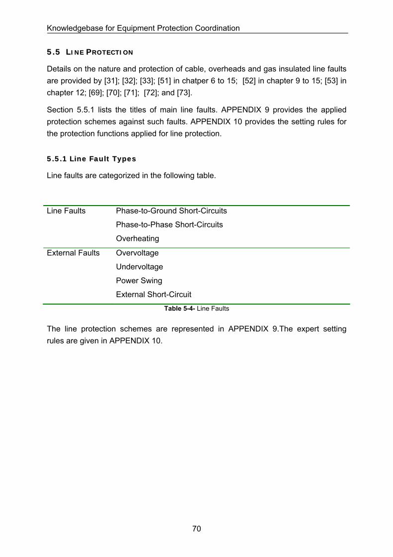
Knowledgebase for Equipment Protection Coordination
55..55 LLIINNEE PPRROOTTEECCTTIIOONN
Details on the nature and protection of cable, overheads and gas insulated line faults are provided by [31]; [32]; [33]; [51] in chatper 6 to 15; [52] in chapter 9 to 15; [53] in chapter 12; [69]; [70]; [71]; [72]; and [73].
Section 5.5.1 lists the titles of main line faults. APPENDIX 9 provides the applied protection schemes against such faults. APPENDIX 10 provides the setting rules for the protection functions applied for line protection.
55..55..11 LLiinnee FFaauulltt TTyyppeess
Line faults are categorized in the following table.
Line Faults Phase-to-Ground Short-Circuits
Phase-to-Phase Short-Circuits
Overheating
External Faults Overvoltage
Undervoltage
Power Swing
External Short-Circuit
Table 5-4- Line Faults
The line protection schemes are represented in APPENDIX 9.The expert setting rules are given in APPENDIX 10.
70
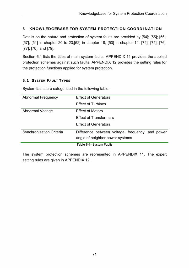
Knowledgebase for System Protection Coordination
66 KKNNOOWWLLEEDDGGEEBBAASSEE FFOORR SSYYSSTTEEMM PPRROOTTEECCTTIIOONN CCOOOORRDDIINNAATTIIOONN
Details on the nature and protection of system faults are provided by [54]; [55]; [56]; [57]; [51] in chapter 20 to 23;[52] in chapter 18; [53] in chapter 14; [74]; [75]; [76]; [77]; [78]; and [79].
Section 6.1 lists the titles of main system faults. APPENDIX 11 provides the applied protection schemes against such faults. APPENDIX 12 provides the setting rules for the protection functions applied for system protection.
66..11 SSYYSSTTEEMM FFAAUULLTT TTYYPPEESS
System faults are categorized in the following table.
Abnormal Frequency
Effect of Generators
Effect of Turbines
Abnormal Voltage Effect of Motors
Effect of Transformers
Effect of Generators
Synchronization Criteria Difference between voltage, frequency, and power angle of neighbor power systems
Table 6-1- System Faults
The system protection schemes are represented in APPENDIX 11. The expert setting rules are given in APPENDIX 12.
71
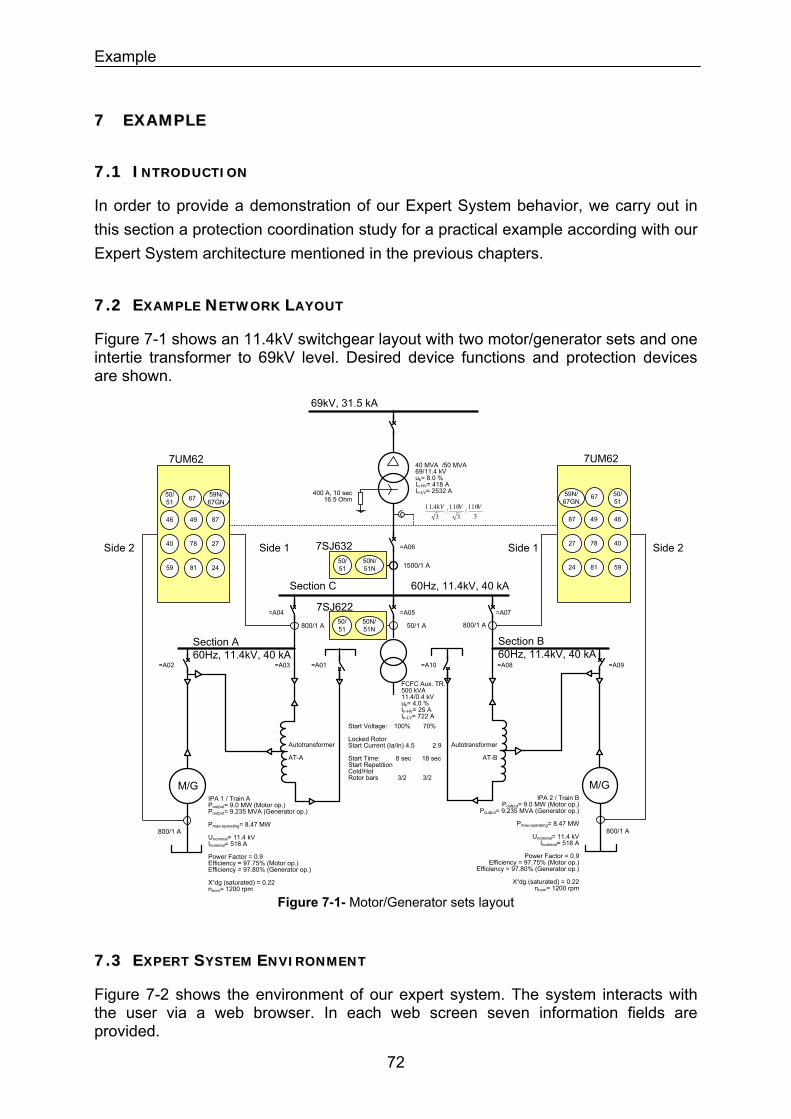
Example
77 EEXXAAMMPPLLEE
77..11 IINNTTRROODDUUCCTTIIOONN
In order to provide a demonstration of our Expert System behavior, we carry out in this section a protection coordination study for a practical example according with our Expert System architecture mentioned in the previous chapters.
77..22 EEXXAAMMPPLLEE NNEETTWWOORRKK LLAAYYOOUUTT
Figure 7-1 shows an 11.4kV switchgear layout with two motor/generator sets and one intertie transformer to 69kV level. Desired device functions and protection devices are shown.
69kV, 31.5 kA
40 MVA /50 MVA69/11.4 kVuk= 8.0 %In-HV= 418 AIn-LV= 2532 A
FCFC Aux. TR.500 kVA11.4/0.4 kVuk= 4.0 %In-HV= 25 AIn-LV= 722 A
=A06
Section C 60Hz, 11.4kV, 40 kA
Section A60Hz, 11.4kV, 40 kA
M/GIPA 1 / Train APoutput= 9.0 MW (Motor op.)Poutput= 9.235 MVA (Generator op.)
Pmax-operating= 8.47 MW
Unominal= 11.4 kVInominal= 518 A
Power Factor = 0.9Efficiency = 97.75% (Motor op.)Efficiency = 97.80% (Generator op.)
X“dg (saturated) = 0.22nnom= 1200 rpm
Start Voltage: 100% 70%
Locked RotorStart Current (Ia/In) 4.5 2.9
Start Time: 8 sec 18 secStart RepetitionCold/Hot Rotor bars 3/2 3/2
Section B60Hz, 11.4kV, 40 kA
M/GIPA 2 / Train B
Poutput= 9.0 MW (Motor op.)Poutput= 9.235 MVA (Generator op.)
Pmax-operating= 8.47 MW
Unominal= 11.4 kVInominal= 518 A
Power Factor = 0.9Efficiency = 97.75% (Motor op.)
Efficiency = 97.80% (Generator op.)
X“dg (saturated) = 0.22nnom= 1200 rpm
800/1 A
800/1 A
7UM62
50/51
Side 2 Side 1
67
46 49 87
40 78 27
59 81 24
59N/67GN
800/1 A
800/1 A
7UM62
50/51
Side 2Side 1
67
464987
407827
598124
59N/67GN
50/1 A50/51
50N/51N
7SJ622
1500/1 A50/51
50N/51N
7SJ632
Autotransformer
AT-A
Autotransformer
AT-B
3110/
3110/
34.11 VVkV
=A05=A04 =A07
=A01 =A10=A02 =A09=A03 =A08
400 A, 10 sec16.5 Ohm
Figure 7-1- Motor/Generator sets layout
77..33 EEXXPPEERRTT SSYYSSTTEEMM EENNVVIIRROONNMMEENNTT
Figure 7-2 shows the environment of our expert system. The system interacts with the user via a web browser. In each web screen seven information fields are provided.
72
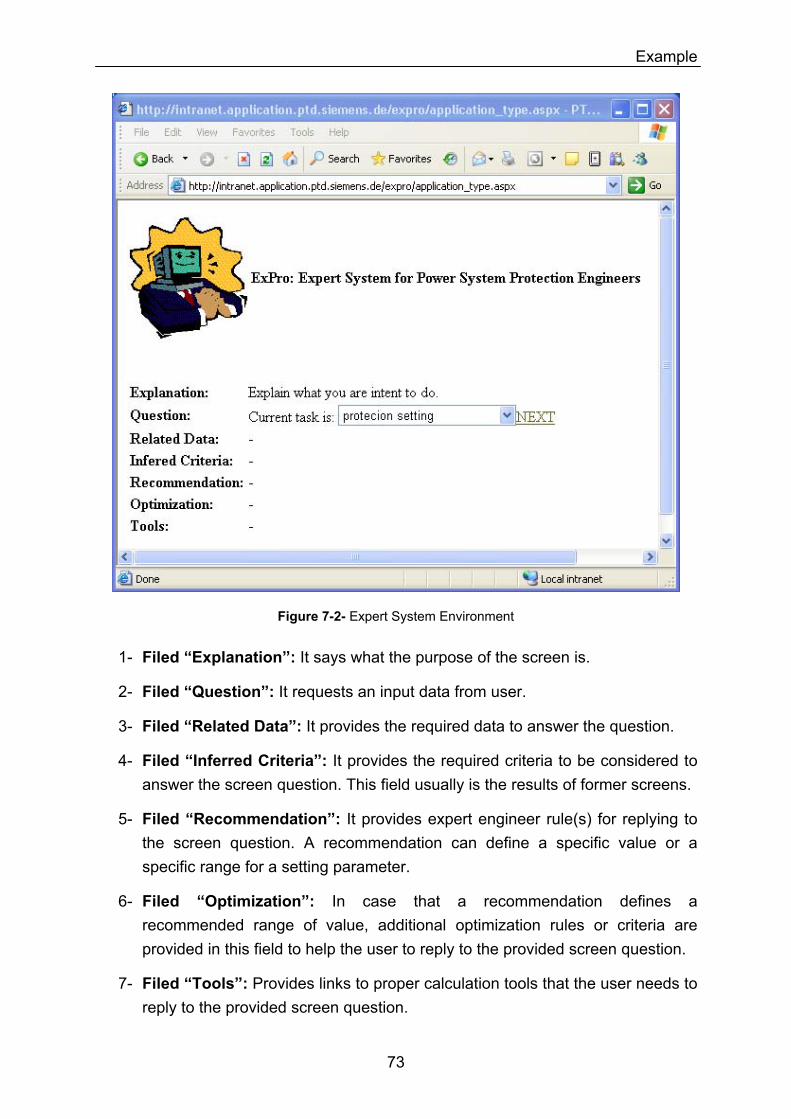
Example
Figure 7-2- Expert System Environment
1- Filed “Explanation”: It says what the purpose of the screen is.
2- Filed “Question”: It requests an input data from user.
3- Filed “Related Data”: It provides the required data to answer the question.
4- Filed “Inferred Criteria”: It provides the required criteria to be considered to answer the screen question. This field usually is the results of former screens.
5- Filed “Recommendation”: It provides expert engineer rule(s) for replying to the screen question. A recommendation can define a specific value or a specific range for a setting parameter.
6- Filed “Optimization”: In case that a recommendation defines a recommended range of value, additional optimization rules or criteria are provided in this field to help the user to reply to the provided screen question.
7- Filed “Tools”: Provides links to proper calculation tools that the user needs to reply to the provided screen question.
73
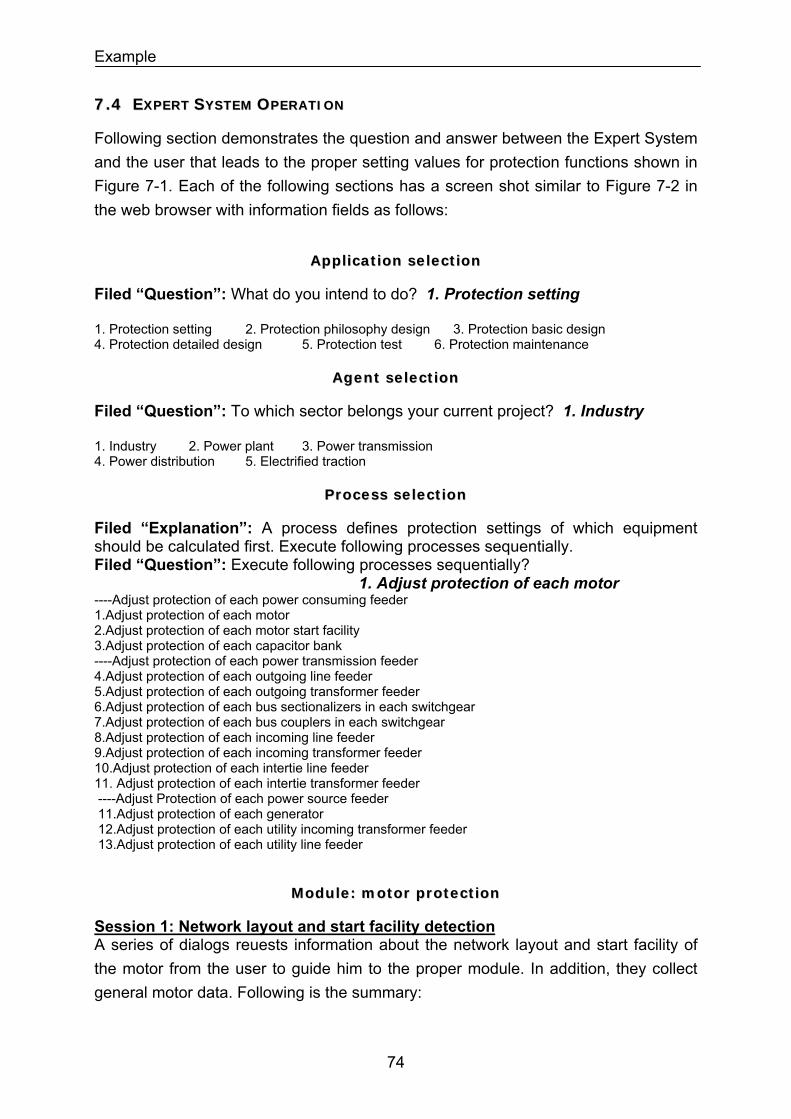
Example
77..44 EEXXPPEERRTT SSYYSSTTEEMM OOPPEERRAATTIIOONN
Following section demonstrates the question and answer between the Expert System and the user that leads to the proper setting values for protection functions shown in Figure 7-1. Each of the following sections has a screen shot similar to Figure 7-2 in the web browser with information fields as follows:
AApppplliiccaattiioonn sseelleeccttiioonn
Filed “Question”: What do you intend to do? 1. Protection setting 1. Protection setting 2. Protection philosophy design 3. Protection basic design 4. Protection detailed design 5. Protection test 6. Protection maintenance
AAggeenntt sseelleeccttiioonn
Filed “Question”: To which sector belongs your current project? 1. Industry 1. Industry 2. Power plant 3. Power transmission 4. Power distribution 5. Electrified traction
PPrroocceessss sseelleeccttiioonn
Filed “Explanation”: A process defines protection settings of which equipment should be calculated first. Execute following processes sequentially. Filed “Question”: Execute following processes sequentially? 1. Adjust protection of each motor ----Adjust protection of each power consuming feeder 1.Adjust protection of each motor 2.Adjust protection of each motor start facility 3.Adjust protection of each capacitor bank ----Adjust protection of each power transmission feeder 4.Adjust protection of each outgoing line feeder 5.Adjust protection of each outgoing transformer feeder 6.Adjust protection of each bus sectionalizers in each switchgear 7.Adjust protection of each bus couplers in each switchgear 8.Adjust protection of each incoming line feeder 9.Adjust protection of each incoming transformer feeder 10.Adjust protection of each intertie line feeder 11. Adjust protection of each intertie transformer feeder ----Adjust Protection of each power source feeder 11.Adjust protection of each generator 12.Adjust protection of each utility incoming transformer feeder 13.Adjust protection of each utility line feeder
MMoodduullee:: mmoottoorr pprrootteeccttiioonn
Session 1: Network layout and start facility detection A series of dialogs reuests information about the network layout and start facility of the motor from the user to guide him to the proper module. In addition, they collect general motor data. Following is the summary:
74
Example
- Is there a motor to adjust its protection settings? YES If no more motor protection is left the system return to the process selection dialog. - Motor ID = IPA1 and IPA2 - Motor Start Scheme =Motor start with autotransformer - Motor Protection Scheme=Motor& start autotransformer have same protections - Motor operation mode = Motor/generator set - Motor Un = 11.4 kV; motor nominal voltage - Motor Pn = 9000 kW; machine nominal output mechanical power; motor mode - Generator Pn = 9235 kW; machine nominal output electrical power; generator mode - Motor In = 518 A; machine nominal current; motor mode - Generator In = 469A; machine nominal current; generator mode - frequency = 60 Hz; system frequency - speed= 1200 r.p.m.;motor nominal speed
FFrraammee SSeelleeccttiioonn:: pprrootteeccttiioonn ffuunnccttiioonnss ooff aa mmoottoorr wwiitthh aauuttoottrraannssffoorrmmeerr
Filed “Explanation”: Select the protection functions designated in your basic design sequentially for setting it up.
Filed “Question”: Selected protection function is: 1. Function 50 (I>): Definite-time overcurrent protection, phase AP 13.1 to AP 13.11 shows a list of around 84 protection functions that can be selected.
Frame: Protection function 51 (Ip>)
A series of dialogs get the following data from the user. Following is the summary:
Function Name= f1; unique name for the protection function
Motor Umin= 70%; motor min. permissible start voltage in percent of nominal voltage;measurement at relay CT
Motor In = 518 A; machine nominal current; motor mode
Motor Is= 2.9x518 A = 1502 A; motor min. start current in Ampere at Umin. ; measurement at relay CT
Motor Ts= 18 sec; motor max. start time at Motor Is.
Then following settings are recommended by expert rules:
SET 51-f1.Ip> = 150% x Motor In = 150% x 518 A = 777 A
SET 51-f1.Curve Type = IEC Normal Inverse
SET 51-f1.T-.Ip>: = 1.52 sec.
75
Example
The time dial and characteristic is set so that the relay trips for motor minimum start voltage in 16 seconds (Motor Ts minus 2 seconds is considered for safety margin). Therefore:
1)/(14.0
02.0 −×=
pPTRIP II
Tt ,
TRIPt =16 sec, = (1502 A) / (777 A) => Tp=1.52 sec )/( pII
Frame: Protection function 50 (I>>)
A series of dialogs get the following data from the user. Following is the summary:
Function Name= f2; unique name for the protection function
Motor Isc= 2590 A;Motor/generator short-circuit contribution to a 3-phase fault at terminal. (Can be estimated as 110% x (x”d-saturated)-1 x Imotor)
Then following settings are recommended by expert rules:
SET 50-f2.I> = 110% x Motor Isc = 110% x 2590 = 2850 A
SET 50-f2.T-.I>: = 0.10 sec.
Frame: Protection function 67 (I>>)
A series of dialogs get the following data from the user. Following is the summary:
Function Name= f3; unique name for the protection function
Motor Umin= 70%; motor min. permissible start voltage in percent of nominal voltage; measurement at relay CT
Motor In = 518 A; machine nominal current; motor mode
Motor Is= 2.9x518 A = 1502 A; motor min. start current in Ampere at Umin. ; measurement at relay CT
Then following settings are recommended by expert rules:
SET 67-f3.I> = 110% x Motor Is = 110% x 1502 = 1652 A
SET 67-f3.T-.I>: = 0.10 sec.
Frame: Protection function 49
A series of dialogs get the following data from the user. Following is the summary:
76
Example
Function Name= f4; unique name for the protection function
Motor Thermal Time Constant thτ = 30 minutes
Motor In = 518 A; machine nominal current; motor mode
Motor Iop-max: 1.05 x 518 A = 544 A; maximum operating current of motor
Trip 49 T-max: 1.05 x 518 A = 544 A; asks the maxi. permissible trip time of overload function when the motor has 150% current overload and has started with 90% preload.
1)/()/()/(
ln. 2
22
max −
−=−
p
ppreloadpthTRIP II
IIIIt τ , =544A , =90%x =490 A, pI preloadI pI
I = 150% x 518A = 777 A and thτ = 30 minutes => = 5.0 minutes max−TRIPt
Then follwing settings are recommended by expert rules:
SET 49-f4.Thermal pickup.Thermal memory= Yes
SET 49- f4.Thermal pickup.θambient measurement= No
SET 49- f4.Current pickup.IAlarm>= Motor Iop-max = 544 A
SET 49- f4.Thermal pickup.IP (ambient or coolant at 40°C)> = Motor Iop-max = 544 A
SET 49- f4.Thermal pickup.Time constant.Tp (ambient or coolant at 40°C) = thτ x( -
1.0 minute safety)/ = 24.0 minutes max−TRIPt
max−TRIPt
SET 49- f4.Thermal pickup.θAlarm> = 90%
SET 49- f4.Thermal pickup.Maximum current for thermal replica: 3.0 x Motor Iop-max = 1632A
Frame: Protection function 46 (I>)
A series of dialogs get the following data from the user. Following is the summary:
Function Name= f5; unique name for the protection function.
Motor In = 518 A; machine nominal current; motor mode.
Motor I2-continuous = 6.5%; permissible continuously negative sequence current in percent of machine nominal current.
Motor = 15 sec;Negative sequence constant ( ) machineK machineKtI =.22
SET 46- f5.warining.I2-continiously permissible>= Motor I2-continuous= 6.5%
SET 46- f5.warining.T-I2-continiously permissible> = 20 seconds.
77
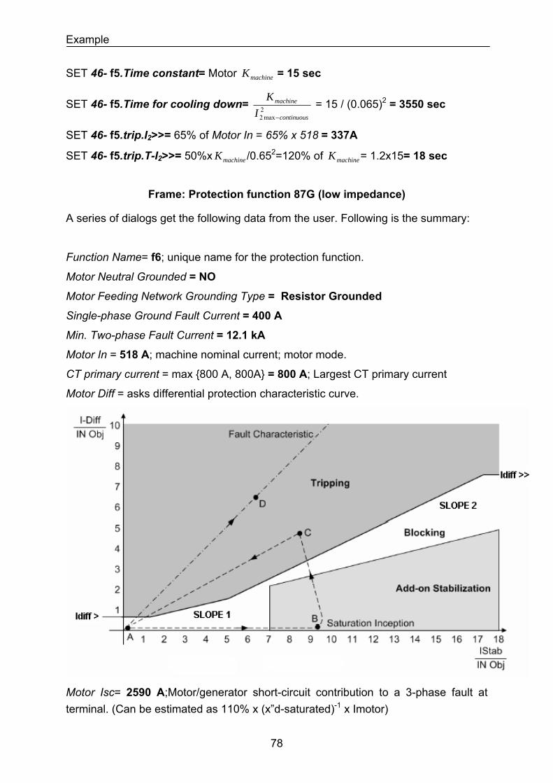
Example
SET 46- f5.Time constant= Motor = 15 sec machineK
SET 46- f5.Time for cooling down= 2max2 continuous
machine
IK
−
= 15 / (0.065)2 = 3550 sec
SET 46- f5.trip.I2>>= 65% of Motor In = 65% x 518 = 337A
SET 46- f5.trip.T-I2>>= 50%x /0.65machineK 2=120% of = 1.2x15= 18 sec machineK
Frame: Protection function 87G (low impedance)
A series of dialogs get the following data from the user. Following is the summary:
Function Name= f6; unique name for the protection function.
Motor Neutral Grounded = NO
Motor Feeding Network Grounding Type = Resistor Grounded
Single-phase Ground Fault Current = 400 A
Min. Two-phase Fault Current = 12.1 kA
Motor In = 518 A; machine nominal current; motor mode.
CT primary current = max 800 A, 800A = 800 A; Largest CT primary current
Motor Diff = asks differential protection characteristic curve.
Motor Isc= 2590 A;Motor/generator short-circuit contribution to a 3-phase fault at terminal. (Can be estimated as 110% x (x”d-saturated)-1 x Imotor)
78
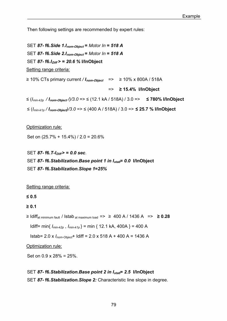
Example
Then following settings are recommended by expert rules:
SET 87- f6.Side 1.Inom-Object = Motor In = 518 A
SET 87- f6.Side 2.Inom-Object = Motor In = 518 A
SET 87- f6.IDiff > = 20.6 % I/InObject
Setting range criteria:
≥ 10% CTs primary current / Inom-Object => ≥ 10% x 800A / 518A
=> ≥ 15.4% I/InObject
≤ (Imin-k2p / Inom-Object /)/3.0 => ≤ (12.1 kA / 518A) / 3.0 => ≤ 780% I/InObject
≤ (Imin-k1p / Inom-Object)/3.0 => ≤ (400 A / 518A) / 3.0 => ≤ 25.7 % I/InObject
Optimization rule:
Set on (25.7% + 15.4%) / 2.0 = 20.6%
SET 87- f6.T-IDiff > = 0.0 sec.
SET 87- f6.Stabilization.Base point 1 in Istab= 0.0 I/InObject
SET 87- f6.Stabilization.Slope 1=25%
Setting range criteria:
≤ 0.5
≥ 0.1
≥ Idiffat minimum fault / Istab at maximum load => ≥ 400 A / 1436 A => ≥ 0.28
Idiff= min Imin-k2p , Imin-k1p = min 12.1 kA, 400A = 400 A
Istab= 2.0 x Inom-Object+ Idiff = 2.0 x 518 A + 400 A = 1436 A
Optimization rule:
Set on 0.9 x 28% = 25%.
SET 87- f6.Stabilization.Base point 2 in Istab= 2.5 I/InObject
SET 87- f6.Stabilization.Slope 2: Characteristic line slope in degree.
79
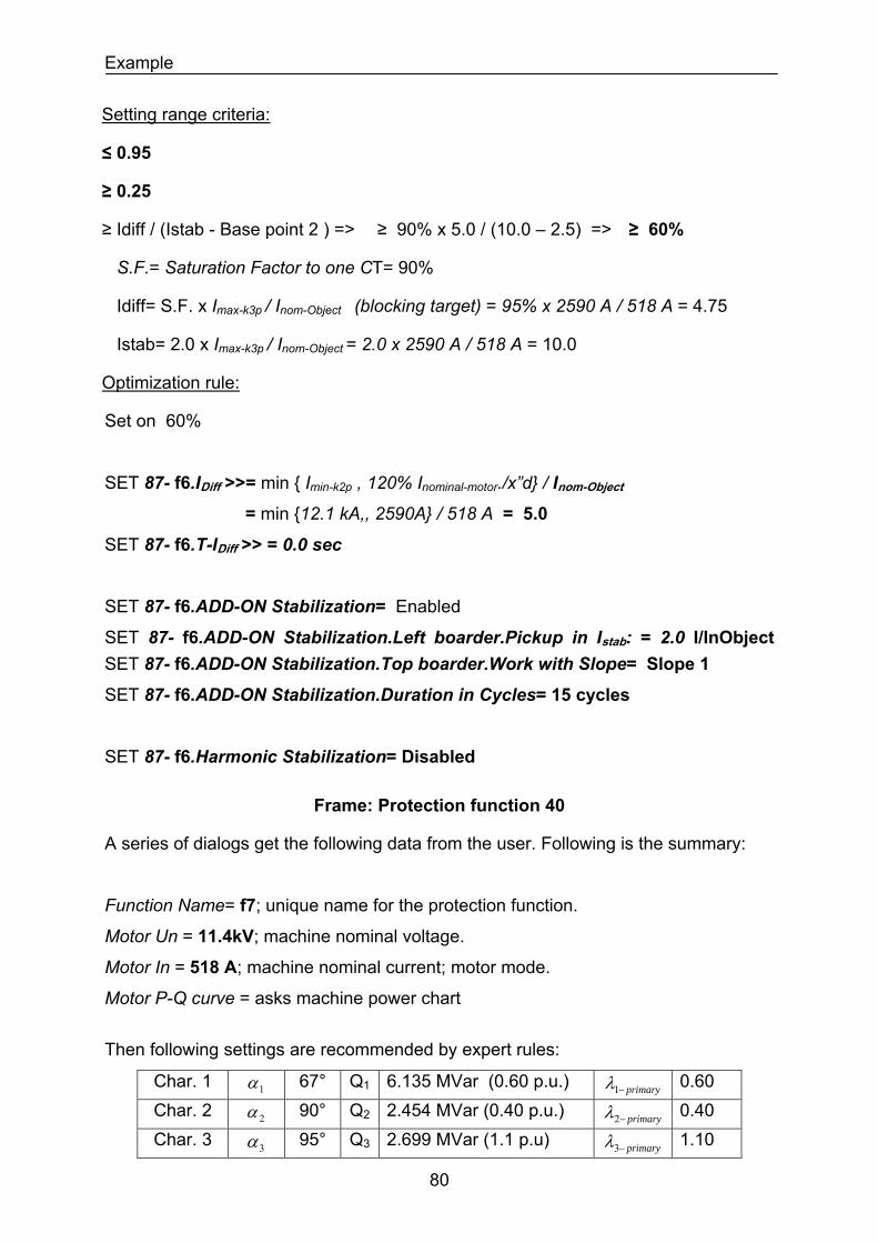
Example
Setting range criteria:
≤ 0.95
≥ 0.25
≥ Idiff / (Istab - Base point 2 ) => ≥ 90% x 5.0 / (10.0 – 2.5) => ≥ 60%
S.F.= Saturation Factor to one CT= 90%
Idiff= S.F. x Imax-k3p / Inom-Object (blocking target) = 95% x 2590 A / 518 A = 4.75
Istab= 2.0 x Imax-k3p / Inom-Object = 2.0 x 2590 A / 518 A = 10.0
Optimization rule:
Set on 60%
SET 87- f6.IDiff >>= min Imin-k2p , 120% Inominal-motor./x”d / Inom-Object
= min 12.1 kA,, 2590A / 518 A = 5.0
SET 87- f6.T-IDiff >> = 0.0 sec
SET 87- f6.ADD-ON Stabilization= Enabled
SET 87- f6.ADD-ON Stabilization.Left boarder.Pickup in Istab: = 2.0 I/InObject SET 87- f6.ADD-ON Stabilization.Top boarder.Work with Slope= Slope 1
SET 87- f6.ADD-ON Stabilization.Duration in Cycles= 15 cycles
SET 87- f6.Harmonic Stabilization= Disabled
Frame: Protection function 40
A series of dialogs get the following data from the user. Following is the summary:
Function Name= f7; unique name for the protection function.
Motor Un = 11.4kV; machine nominal voltage.
Motor In = 518 A; machine nominal current; motor mode.
Motor P-Q curve = asks machine power chart
Then following settings are recommended by expert rules:
Char. 1 1α 67° Q1 6.135 MVar (0.60 p.u.) primary−1λ 0.60 Char. 2 2α 90° Q2 2.454 MVar (0.40 p.u.) primary−2λ 0.40 Char. 3 95° Q3 2.699 MVar (1.1 p.u) 3α primary−3λ 1.10
80
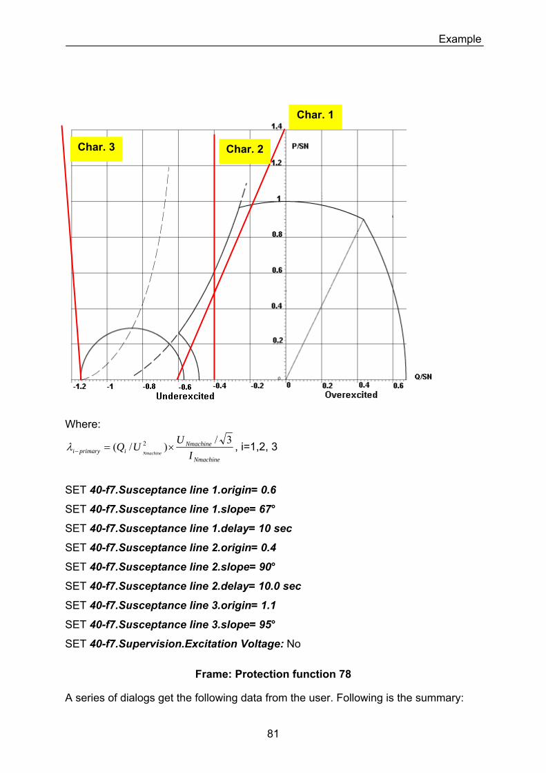
Example
Char. 1
Char. 3 Char. 2
Where:
Nmachine
Nmachineiprimaryi I
UUQNmachine
3/)/( 2 ×=−λ , i=1,2, 3
SET 40-f7.Susceptance line 1.origin= 0.6
SET 40-f7.Susceptance line 1.slope= 67°
SET 40-f7.Susceptance line 1.delay= 10 sec
SET 40-f7.Susceptance line 2.origin= 0.4
SET 40-f7.Susceptance line 2.slope= 90°
SET 40-f7.Susceptance line 2.delay= 10.0 sec
SET 40-f7.Susceptance line 3.origin= 1.1
SET 40-f7.Susceptance line 3.slope= 95°
SET 40-f7.Supervision.Excitation Voltage: No
Frame: Protection function 78
A series of dialogs get the following data from the user. Following is the summary:
81
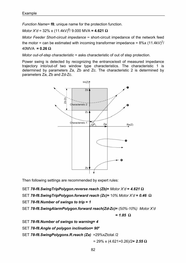
Example
Function Name= f8; unique name for the protection function.
Motor X’d = 32% x (11.4kV)2/ 9.000 MVA = 4.621 Ω
Motor Feeder Short-circuit impedance = short-circuit impedance of the network feed the motor = can be estimated with incoming transformer impedance = 8%x (11.4kV)2/ 40MVA = 0.26 Ω
Motor out-of-step characteristic = asks characteristic of out of step protection.
Power swing is detected by recognizing the entrance/exit of measured impedance trajectory into/out-of two window type characteristics. The characteristic 1 is determined by parameters Za, Zb and Zc. The characteristic 2 is determined by parameters Za, Zb and Zd-Zc.
Then following settings are recommended by expert rules: SET 78-f8.SwingTripPolygon.reverse reach (Zb)= Motor X’d = 4.621 Ω
SET 78-f8.SwingTripPolygon.forward reach (Zc)= 10% Motor X’d = 0.46 Ω
SET 78-f8.Number of swings to trip = 1
SET 78-f8.SwingAlarmPolygon.forward reach(Zd-Zc)= (50%-10%) Motor X’d
= 1.85 Ω
SET 78-f8.Number of swings to warning= 4
SET 78-f8.Angle of polygon inclination= 90°
SET 78-f8.SwingPolygons.R.reach (Za) =29%xZtotal /2
= 29% x (4.621+0.26)/2= 2.55 Ω
82
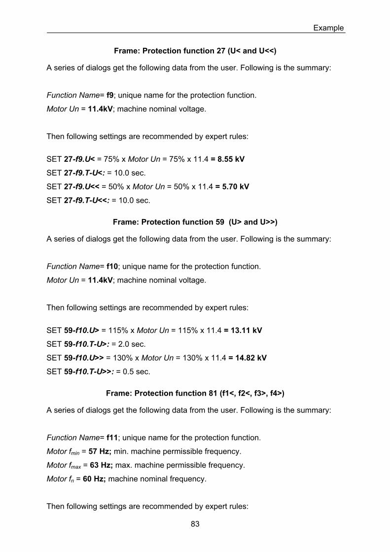
Example
Frame: Protection function 27 (U< and U<<)
A series of dialogs get the following data from the user. Following is the summary:
Function Name= f9; unique name for the protection function.
Motor Un = 11.4kV; machine nominal voltage.
Then following settings are recommended by expert rules:
SET 27-f9.U< = 75% x Motor Un = 75% x 11.4 = 8.55 kV
SET 27-f9.T-U<: = 10.0 sec.
SET 27-f9.U<< = 50% x Motor Un = 50% x 11.4 = 5.70 kV
SET 27-f9.T-U<<: = 10.0 sec.
Frame: Protection function 59 (U> and U>>)
A series of dialogs get the following data from the user. Following is the summary:
Function Name= f10; unique name for the protection function.
Motor Un = 11.4kV; machine nominal voltage.
Then following settings are recommended by expert rules:
SET 59-f10.U> = 115% x Motor Un = 115% x 11.4 = 13.11 kV
SET 59-f10.T-U>: = 2.0 sec.
SET 59-f10.U>> = 130% x Motor Un = 130% x 11.4 = 14.82 kV
SET 59-f10.T-U>>: = 0.5 sec.
Frame: Protection function 81 (f1<, f2<, f3>, f4>)
A series of dialogs get the following data from the user. Following is the summary:
Function Name= f11; unique name for the protection function.
Motor fmin = 57 Hz; min. machine permissible frequency.
Motor fmax = 63 Hz; max. machine permissible frequency.
Motor fn = 60 Hz; machine nominal frequency.
Then following settings are recommended by expert rules:
83
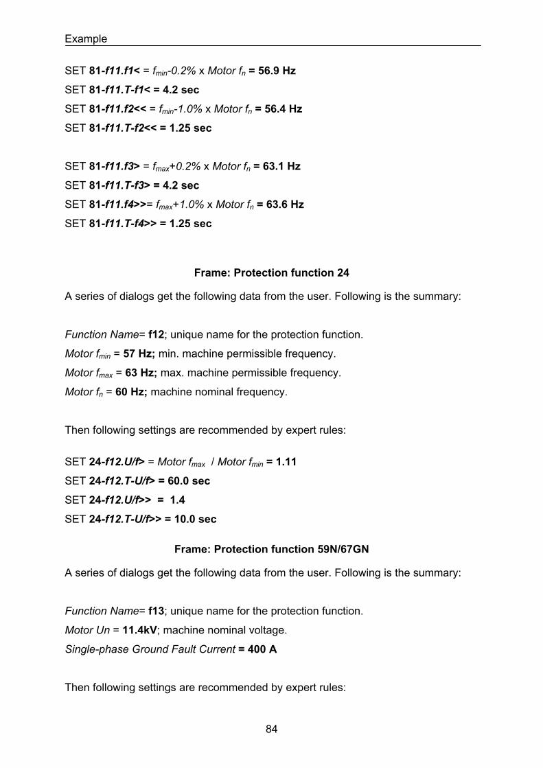
Example
SET 81-f11.f1< = fmin-0.2% x Motor fn = 56.9 Hz
SET 81-f11.T-f1< = 4.2 sec
SET 81-f11.f2<< = fmin-1.0% x Motor fn = 56.4 Hz
SET 81-f11.T-f2<< = 1.25 sec
SET 81-f11.f3> = fmax+0.2% x Motor fn = 63.1 Hz
SET 81-f11.T-f3> = 4.2 sec
SET 81-f11.f4>>= fmax+1.0% x Motor fn = 63.6 Hz
SET 81-f11.T-f4>> = 1.25 sec
Frame: Protection function 24
A series of dialogs get the following data from the user. Following is the summary:
Function Name= f12; unique name for the protection function.
Motor fmin = 57 Hz; min. machine permissible frequency.
Motor fmax = 63 Hz; max. machine permissible frequency.
Motor fn = 60 Hz; machine nominal frequency.
Then following settings are recommended by expert rules:
SET 24-f12.U/f> = Motor fmax / Motor fmin = 1.11
SET 24-f12.T-U/f> = 60.0 sec
SET 24-f12.U/f>> = 1.4
SET 24-f12.T-U/f>> = 10.0 sec
Frame: Protection function 59N/67GN
A series of dialogs get the following data from the user. Following is the summary:
Function Name= f13; unique name for the protection function.
Motor Un = 11.4kV; machine nominal voltage.
Single-phase Ground Fault Current = 400 A
Then following settings are recommended by expert rules:
84
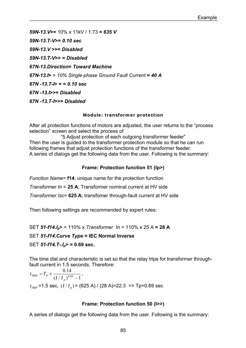
Example
59N-13.V>= 10% x 11kV / 1.73 = 635 V
59N-13.T-V>= 0.10 sec
59N-13.V >>= Disabled
59N-13.T-V>> = Disabled
67N-13.Direction= Toward Machine
67N-13.I> = 10% Single-phase Ground Fault Current = 40 A
67N -13.T-I> = = 0.10 sec
67N -13.I>>= Disabled
67N -13.T-I>>= Disabled
MMoodduullee:: ttrraannssffoorrmmeerr pprrootteeccttiioonn
After all protection functions of motors are adjusted, the user returns to the “process selection” screen and select the process of
“5.Adjust protection of each outgoing transformer feeder” Then the user is guided to the transformer protection module so that he can run following frames that adjust protection functions of the transformer feeder. A series of dialogs get the following data from the user. Following is the summary:
Frame: Protection function 51 (Ip>)
Function Name= f14; unique name for the protection function
Transformer In = 25 A; Transformer nominal current at HV side
Transformer Isc= 625 A; transfomer through-fault current at HV side
Then following settings are recommended by expert rules:
SET 51-f14.Ip> = 110% x Transformer In = 110% x 25 A = 28 A
SET 51-f14.Curve Type = IEC Normal Inverse
SET 51-f14.T-.Ip> = 0.69 sec.
The time dial and characteristic is set so that the relay trips for transformer through-fault current in 1.5 seconds. Therefore:
1)/(14.0
02.0 −×=
pPTRIP II
Tt ,
TRIPt =1.5 sec, = (625 A) / (28 A)=22.3 => Tp=0.69 sec )/( pII
Frame: Protection function 50 (I>>)
A series of dialogs get the following data from the user. Following is the summary:
85
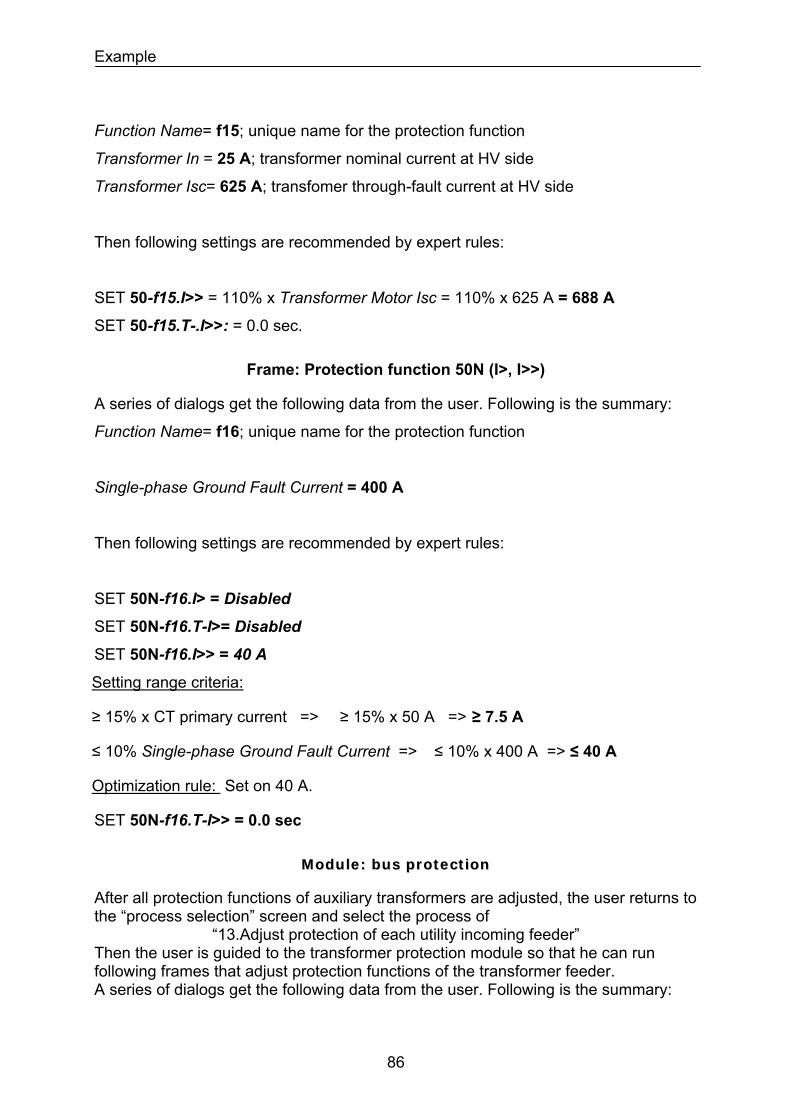
Example
Function Name= f15; unique name for the protection function
Transformer In = 25 A; transformer nominal current at HV side
Transformer Isc= 625 A; transfomer through-fault current at HV side
Then following settings are recommended by expert rules:
SET 50-f15.I>> = 110% x Transformer Motor Isc = 110% x 625 A = 688 A
SET 50-f15.T-.I>>: = 0.0 sec.
Frame: Protection function 50N (I>, I>>)
A series of dialogs get the following data from the user. Following is the summary:
Function Name= f16; unique name for the protection function
Single-phase Ground Fault Current = 400 A
Then following settings are recommended by expert rules:
SET 50N-f16.I> = Disabled
SET 50N-f16.T-I>= Disabled
SET 50N-f16.I>> = 40 A
Setting range criteria:
≥ 15% x CT primary current => ≥ 15% x 50 A => ≥ 7.5 A
≤ 10% Single-phase Ground Fault Current => ≤ 10% x 400 A => ≤ 40 A
Optimization rule: Set on 40 A.
SET 50N-f16.T-I>> = 0.0 sec
MMoodduullee:: bbuuss pprrootteeccttiioonn
After all protection functions of auxiliary transformers are adjusted, the user returns to the “process selection” screen and select the process of
“13.Adjust protection of each utility incoming feeder” Then the user is guided to the transformer protection module so that he can run following frames that adjust protection functions of the transformer feeder. A series of dialogs get the following data from the user. Following is the summary:
86
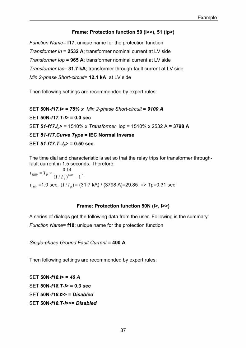
Example
Frame: Protection function 50 (I>>), 51 (Ip>)
Function Name= f17; unique name for the protection function
Transformer In = 2532 A; transformer nominal current at LV side
Transformer Iop = 965 A; transformer nominal current at LV side
Transformer Isc= 31.7 kA; transformer through-fault current at LV side
Min 2-phase Short-circuit= 12.1 kA at LV side
Then following settings are recommended by expert rules:
SET 50N-f17.I> = 75% x Min 2-phase Short-circuit = 9100 A
SET 50N-f17.T-I> = 0.0 sec
SET 51-f17.Ip> = 1510% x Transformer Iop = 1510% x 2532 A = 3798 A
SET 51-f17.Curve Type = IEC Normal Inverse
SET 51-f17.T-.Ip> = 0.50 sec.
The time dial and characteristic is set so that the relay trips for transformer through-fault current in 1.5 seconds. Therefore:
1)/(14.0
02.0 −×=
pPTRIP II
Tt ,
TRIPt =1.0 sec, = (31.7 kA) / (3798 A)=29.85 => Tp=0.31 sec )/( pII
Frame: Protection function 50N (I>, I>>)
A series of dialogs get the following data from the user. Following is the summary:
Function Name= f18; unique name for the protection function
Single-phase Ground Fault Current = 400 A
Then following settings are recommended by expert rules:
SET 50N-f18.I> = 40 A
SET 50N-f18.T-I> = 0.3 sec
SET 50N-f18.I>> = Disabled
SET 50N-f18.T-I>>= Disabled
87
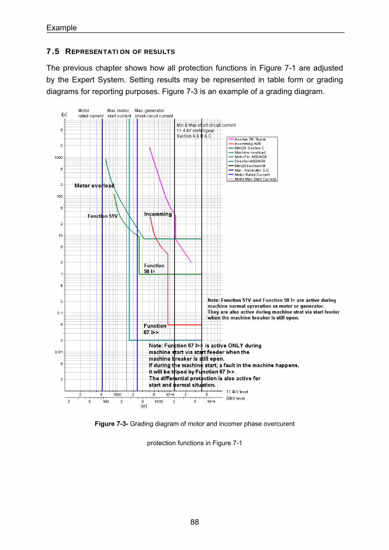
Example
77..55 RREEPPRREESSEENNTTAATTIIOONN OOFF RREESSUULLTTSS
The previous chapter shows how all protection functions in Figure 7-1 are adjusted by the Expert System. Setting results may be represented in table form or grading diagrams for reporting purposes. Figure 7-3 is an example of a grading diagram.
Figure 7-3- Grading diagram of motor and incomer phase overcurent
protection functions in Figure 7-1
88

Summary and Future Works
88 SSUUMMMMAARRYY AANNDD FFUUTTUURREE WWOORRKKSS
We have collected the knowledge of experienced protection engineers which provides a coordinated protection settings for the protection of equipments (Bus, Generator, Motor, Transformer, Reactor and Line) and power systems.
Experienced engineers apply their know-how step-by-step to carry out the protection coordination task. The Expert System imitates this behavior of expert engineers in a web-based application.
This work has decomposed the protection knowledge of experts into smaller elements: the setting rules. Each setting rule is valid for definite conditions. Therefore, a sequence of dialogs is asked from the Expert System user to fulfill the required validity condition of each rule. Each dialog contains the following parts: Question, Answer, Criteria, Recommendation and Optimization.
The sequence of which dialogs are asked as well as the question and the recommendation part of each dialog designed are based on the know-how knowledge of the expert engineers.
Each dialog recommends either a setting value or a setting criterion for each parameter of each protection function in each protection device. The generated setting criteria are optimized to provide the shortest fault clearing time or the longest equipment or system operation time. In each dialog, the Expert System user may accept the proposed recommendation or dictate his proposed value.
The pilot Expert System can be extended in two directions: depth and coverage.
The protection coordination knowledge can be enriched to provide a higher level of expertise for coordinated protection of power systems and equipments. Validation and revise of protection system settings to prevent power system blackout and cascading trip, and the addition of new protection settings rules for new equipments are examples that increase the knowledge depth of the pilot Expert System.
On the other hand, a new area of knowledge can be added to the pilot system. Protection philosophy design, protection basic design, protection detailed design, protection commissioning, protection testing and protection maintenance are new areas to extend the knowledge coverage of the pilot Expert System.
89
List of References
99 LLIISSTT OOFF RREEFFEERREENNCCEESS
Literature on Expert Systems [1] MCCARTHY, J.: Programs with Common Sense, Proceedings of the Symposium on
Mechanization of Thought Processes, Vol. 1, London, pp. 77-84, 1958.
[2] NEWWELL, A.; SIMON, H.A.: GPS, a Program That Simulate Human Thought, Lernende
Automatten, H.Billing ed., R. Oldenbourg, Munich, pp. 109-124, 1961.
[3] MCCULLOCH, W.S.; PITTS, W.: A Loggical Calculus of the Ideas Immanent in Nervous
Activity, Bulletin of Mathematical and Biophysics, Vol. 5, pp. 115-137, 1943.
[4] WATERMAN, D. A.: A Guide to Expert Systems. Addison-Wesley, Reading, MA. USA,
1986, ISBN 0-201-08313-2.
[5] NEGNEVITSKY, M.: Artificial Intelligence: A Guide to Intelligent Systems. 2nd edition,
Addison-Wesley, Harlow UK, 2005, ISBN 0-321-20466-2.
[6] DURKIN, J.: Expert System Design and Development. Prentic Hall, Engelwood Clifs, NY.
USA, 1994, ISBN 0-023-30970-9.
[7] GIARRATANO J.C, RIELY G.D.: Expert System: Principles and Programming. 4th edition,
Course Technology, a division of Tomsom Learning Inc., Canada, 2005, ISBN 0-534-
38447-1.
[8] Proceedings of the Symposia on Expert/Intelligent Systems Application to Power
Systems: Sweden/ Stockholm-Helsinki (1988), USA/Seattle (1989), Tokyo/Kobe (1991),
Australia/Melbourne (1993), Montpellier (1995), USA/Orlando (1996), Korea/Seoul
(1997), Brazil/Rio de Janeiro (1999), Hungary/ Budapest (2001), Greek/Lemnos
(2003), USA/ Washington D.C. -Arlington (2005)
[9] EL-ARROUDI K.; JOOS G.; MCGILLS D.T.; BREARLEY R.: Comprehensive Transmission
Distance Protection Settings Using an Intelligent-Based Analysis of Events and
Consequences, IEEE Trans. on Power Delivery, vol. 20, pp. 1817-1824, July 2005.
[10] MIN B.W.; LEE S.J.; CHOI M.S.; KANG S.H.; HYUN S.H.; KIM H.P.; ROH J.H.; HONG J.W.:
Automated Relay Setting And Protection Database Management System, Proc. CIGRE
2004, Paris, France, September 2004.
[11] MCGUIRE P.F.; PATTERSON R.W.; GIULIANTE A.T.; HOLT G.R.: Automated Setting of Relays
for Transmission Line Pilot Protection, Proc. CIGRE 2004, Paris, France, September
2004.
90
List of References
[12] ORDUNA E.; GARCE F.; HANDSCHIN E.: Algorithmic-Knowledge-Based Adaptive
Coordination in Transmission Protection, IEEE Trans. on Power Delivery, vol. 18, No. 1,
pp. 61-65, January 2003.
[13] EL-FERGANY A.:Protective Devices Coordination Toolbox Enhanced by an Embedded
Expert System–Medium & Low Voltage Levels, CIRED 2003, Barcelona,Spain,May 2003.
[14] TAN J.C.; CROSSLY P.A.; MCLAREN P.G.; GALE P.F.; HALL I.; FARREL J.: Application of a
Wide-Area Backup Protection Expert System to Prevent Cascading Outages, IEEE
Transaction on Power Delivery, Vol. 17, No. 2, pp. 375-380, Apr. 2002.
[15] TAN J.C.; CROSSLY P.A.; KIRSCHEN D.; GOODY J.; DOWNES J.A.: An Expert System for
Backup Protection of Transmission Network, IEEE Transaction on Power Delivery, Vol.
15, No. 2, pp. 508-514, Apr. 2000.
[16] KEZUNOVIC M.: Inteliegent Systems in Protection Engineering, Proc. PowerCon 2000,
Perth, Western Australia, Dec. 2000.
[17] IEEE WORKING GROUP C-4 FINAL REPORT, "Intelligent Systems in Protection Engineering,"
IEEE PES PSRC, February 1999.
[18] AGGARWAL, RAJ: Atrifical Intelligence Techniques in Power system, IEE Power
Engineering series 22, Bookcraft U.K., 1997, ISBN 0-85296-897-3.
[19] JONGEPIER A.G., VAN DER SLUIS L.: Adaptive Distance Protection of Double-Circuit Lines
using Artificial Neural Network, IEEE Trans. on Power Delivery, vol. 12, No. 1, pp. 97-
105, Jan. 1997.
[20] GALIANA F.D.; MANOLIU R; ROSU C.; HUNEALT M.: A Study of Knowledge Engineering Tools
in Power Engineering Applications, IEEE Trans. on Power Systems, vol. 9, No. 4, pp.
1825-1832, Nov. 1994.
[21] BROADWATER R.P.; THOMPSON J.C.; RAHMAN S.; SARGENT A.: An Expert System for
Integrated Protection design with Configurable Distribution Circuits: Part I, IEEE Trans.
on Power Delivery, vol. 9, No. 2, pp. 1115-1121, April 1994.
[22] BROADWATER R.P.; THOMPSON J.C.; RAHMAN S.; SARGENT A.: An Expert System for
Integrated Protection design with Configurable Distribution Circuits: Part II, IEEE
Trans. on Power Delivery, vol. 9, No. 2, pp. 1122-1128, April 1994.
[23] IEEE POWER SYSTEM RELAYING COMMITTEE, WORKING GROUP D-10: Potential Applications of
Expert Systems to Power System Protection, IEEE Trans. on Power Delivery, vol. 9, No.
2, pp. 720-728, April 1994.
91
List of References
[24] Tomsovic Kevin: Tutorial on Knowledge-Based System Techniques with Application to
Power systems. IEEE 1994 Winter Meeting, ISBN New York NY USA, February 1994.
[25] IEEE POWER ENGINEERING SOCIETY: A Tutorial Course on Knowledge-Based System
Techniques with Application to Power systems. IEEE Catalog Number: 93EHO-387-1-
PWR,ISBN Softbond 0-7803-9984-6, NJ USA, October 1993.
[26] HONG H.W.; SUN C.T.; MEASA V.M.; STEVEN NG: Protective Device Coordination Expert
System, IEEE Trans. on Power Delivery, vol. 6, No. 1, pp. 359-365, January 1991.
[27] LEE S.J.; YOON S.H.; YOON M.C.; JANG J.K.: An Expert System for Protective Relay
Settings of Transmission Systems, IEEE Trans. on Power Delivery, vol. 5, No. 2, pp.
1202-1208, April 1990.
[28] ZAHNG Z.Z.; HOPE G.S.; MALIK O.P.: Expert Systems in Electric Power Systems – A
Biblographical Survey, IEEE Trans. on Power Systems, vol. 4, No. 4, pp. 1355-1362,
Oct. 1989.
Literature on Protection Functions and Devices [29] IEEE STANDARD C37.2-1996: IEEE Standard Electrical Power System Device Function
Number and Contact Designations. IEEE, New York, 1996.
[30] SIEMENS AG, POWER TRANSMISSION AND DISTRIBUTION GROUP: Power Engineering Guide:
Transmission and Distribution. 4nd edition, Power to the Point, Germany, Order No.
E50001-U700-A68-X-7600.
[31] SIEMENS AG: SIPROTEC Multi-Function Protective Relay with Local Control 7SJ62/63/64
V4.6 Manual. Order No. C53000-G1140-C147-7.
[32] SIEMENS AG: SIPROTEC Differential Protection 7UT6 V4.0 Manual
7U613/7UT633/7UT635. Order No. C53000-G1176-C160-1.
[33] SIEMENS AG: SIPROTEC Differential Protection 7SD610 V4.0 Manual. Order No. C53000-
G1176-C145-1.
[34] SIEMENS AG: SIPROTEC Distributed Busbar/Breaker Failure Protection 7SS52
v4.6/7SS523 V3.2/ 7SS525 V3.2 Manual. Order No. C53000-G1176-C182-1.
[35] SIEMENS AG: SIPROTEC Centralized Numerical Busbar Protection 7SS60 V3.1. Order No.
E50417-G1176-C132-A1.
[36] SIEMENS AG: SIPROTEC Distance Protection 7SA6 V4.61 Manual. Order No. C53000-
G1176-C156-5.
92
List of References
[37] SIEMENS AG: SIPROTEC Numerical Overhead Contact Line Protection for AC Traction
Power Supply 7ST6 V4.2 Manual. Order No. E50417-G1176-C251-A3.
[38] SIEMENS AG: SIPROTEC Multifunction Paralleling Devices 7VE61 and 7VE63 V4.0
Manual. Order No. C53000-G1176-C163-1.
[39] SIEMENS AG: SIPROTEC Breaker Management Relay 7VK61 V4.0 Manual. Order No.
C53000-G1176-C159-1.
[40] SIEMENS AG: Numerical Voltage, Frequency, and Overflux Protection: SIPROTEC
7RW600 V3.0 Instruction Manual. Order No. C53000-G1176-C117-4.
[41] SIEMENS AG: SIPROTEC 7VH60 V1.0: High-Impedance Differential Relay. Order No.
C53000-B1176-C136-1.
[42] SIEMENS AG: SIPROTEC Multifunction Machine Protection 7UM62 V4.6 Manual. Order
No. C53000-G1176-C149-5.
Literature on Equipment and System Protection Coordination [43] ZIEGLER, GERHARD: Numerical Distance Protection Princliples and Applications. first
edition, SIEMENS Publicis Corporate Publishing, Erlangen, 1999, ISBN 3-89578-141-X.
[44] ZIEGLER, GERHARD: Numerical Distance Protection Princliples and Applications. 2nd
edition, SIEMENS Publicis Corporate Publishing, Erlangen, 2006, ISBN 3-89578-266-1.
[45] ZIEGLER, GERHARD: Numerical Differential Protection Princliples and Applications. fisrt
edition, SIEMENS Publicis Corporate Publishing, Erlangen, 2005, ISBN 3-89578-234-3.
[46] WARRINGTON, A.R. VAN C.: Protective Relays: their Theory and Practice. Volume 1.
Chapmann and Hall, London. UK, 1962.
[47] HAUBRICH, H.-J; HOSEMANN , G: THOMAS, R.: Single-Phase Auto-Reclosing in EHV
systems. CIGRE Session -31-09, August 1974.
[48] KIMBARK, E. W.: Suppression of ground fault arcs on single-pole-switched EHV lines by
shunt reactors. IEEE Transactions PAS-83, 1964, pp. 285-290.
[49] IEEE POWER SYSTEM RELAYING COMMITTEE REPORT: Single phase tripping and Auto-
Reclosing of transmission lines. IEEE Transactions on Power Delivery, Vol. 7 No.1,
January 1992.
[50] HOROWITZ, S.H.; PHADKE, A.G.: Third Zone Revisited, IEEE Transactions on Power
Delivery Vol. 21, No. 1, January 2006, pp. 23-29.
93
List of References
[51] ANDERSON, P.M.: Power System Protection, IEEE Press, NJ USA, 1998, ISBN 0-7803-
3427-2.
[52] ALSTOM: Network Protection & Automation Guide, ALSTOM T&D Energy Automation
and Information, Levallois-Perret France, First Edition 2002, ISBN 2-9518589-0-6.
[53] BLACKBURN, J. LEWIS: Protective Relaying Principles and Applications, Marcel Dekker Inc,
New York and Basel, 1987, ISBN 0-8247-7445-0.
[54] KUNDUR, PRABHA: Power System Stability and Control, Electric Power Reseach Institute
(EPRI), McGraw-Hill Inc., New York, 1993, ISBN 0-07-035958-X.
[55] TAYLOR CARSON W.: Power System Voltage Stability, Electric Power Reseach Institute
(EPRI), Power System Engineering Series, Kluwer Academic Publishers,
Boston/London/Dordrecht, 1998 (reprint 2001), ISBN: 0-7923-8139-4.
[56] THIERRY VAN CUTSEM; COASTAS VOURNAS: Voltage Stability of Electric Power Systems,
Power Electronic and Power System Series, McGraw-Hill Inc., New York, 1994, ISBN 0-
07-063184-0.
[57] WAREN, C. NEW: Load Shedding, Load Restoration and Generator Protection using Solid
State and Electromechanical Underfrequency Relays, Switchgear Business Department,
General Electric Company, Philadelphia Pa. 19142, GE reference code GET-6449.
[58] SCHOSSIG, WALTER: Netzschutztechnik, Anlagetechnik für Elektrische Verteilungsnetze:
Band 13, VDE-Verlag GMBH, Berlin-Offenbach Germany, 1997, ISBN 3-8007-2232-1.
[59] IEEE STANDARD C37.97-1979: IEEE Guide for Protective Relay Applications to Power
System Buses. IEEE, New York, 1990.
[60] SIEMENS AG, Roeper, R.; Ehmcke B.; Webers A.: Short-Circuit Currents in Three-Phase
Systems., 2nd Edition, Siemens AG with John Wiley and Sons, New York USA, 1985,
ISBN 3-8009-1427-1 (Siemens AG); ISBN: 0-471-90707-3 (Wiley).
[61] Schlabbach Jürgen: Kurzschlussstromberechnungen, Anlagentechnik für elektrische
Vertailungsnetze: Band 18, VDE-Verlag GMBH, Berlin-Offenbach Germany, 2003, ISBN
3-8022-0739-4.
[62] IEEE STANDARD C37.102-1995: IEEE Guide for AC Generator Protection. IEEE, New
York, 1995.
[63] IEEE STANDARD C37.96-2000: IEEE Guide for AC Motor Protection. IEEE, New York,
2000.
94
List of References
[64] IEEE STANDARD C57.12.00-2000: IEEE Standard General Requirements for Liquid-
Immersed Distribution, Power and Regulating Transformers. IEEE, New York, 2000.
[65] IEEE STANDARD C37.91-2000: IEEE Guide for Protective Relay Applications to Power
Transformers. IEEE, New York, 2000.
[66] IEEE STANDARD C37.108-1989: IEEE Guide for Protection of Network Transformers.
IEEE, New York, 1989.
[67] IEEE STANDARD C37.135-2001: IEEE Guide for Application, Specification and Testing of
Phase-Shifting Transformers. IEEE, New York, 2001.
[68] IEEE STANDARD C37.109-1988: IEEE Guide for Protection of Shunt Reactors. IEEE, New
York, 1988.
[69] IEEE STANDARD C37.113-1999: IEEE Guide for Protective Relay Applications to
Transmission Lines. IEEE, New York, 1999.
[70] IEEE POWER SYSTEM RELAYING COMMITTEE OF THE POWER ENGINEERING SOCIETY: Computer
Aided Coordination of Line Protection Schemes. IEEE Catalog Number: 90TH0-285-7-
PWR, NJ USA, 1989.
[71] CIGRE JOINT WORKING GROUP 34/35.11: Protection Using Teleprotections. CIGRE,
August, 2001.
[72] CIGRE WORKING GROUP 04 OF STUDY COMMITTEE 34: Application Guide on Protection of
Complex Transmission Network Configuration. CIGRE, November, 1991.
[73] IEEE STANDARD C37.487-1992: IEEE Recommended Practice for Protection of Wire-Line
Communication Facillities Serving Electric Power Stations. IEEE, New York, 1992.
[74] VDN: Transmission Code 2003, Network and System Rules of the German Transmission
System Operators. VDN (VERBAND DER NETZBETREIBER) e.V. beim VDEW, Berlin, August,
2003.
[75] IEEE STANDARD C37.242-2001 (IEEE BUFF BOOK): IEEE Recommended Practice for
Protection and Coordination of Industrial and Commercial Power Systems. IEEE, New
York, 2001.
[76] IEEE STANDARD C37.141-1993 (IEEE RED BOOK): IEEE Recommended Practice for
Electric Power Distribution for Industrial Plants. IEEE, New York, 1993.
[77] IEEE STANDARD C37.142-1991: IEEE Recommended Practice for Grounding of Industrial
and Commercial Power Systems. IEEE, New York, 1991.
95
List of References
[78] Schlabbach Jürgen: Sternpunktbehandlung, Anlagentechnik für elektrische
Vertailungsnetze: Band 15, VDE-Verlag GMBH, Berlin-Offenbach Germany, 2003, ISBN
3-8022-0739-4.
[79] Zube Bernhard: Selektiveschutz für elektrische Netze und Anlagen, VDE-Verlag GMBH,
Berlin-Offenbach Germany, 1997, ISBN 3-8007-1628-3.
[80] Herrman, H.J.: Digitale Schutztechnik Grundlagen, Software, Ausführungsbaispiele.,
VDE-Verlag GMBH, Berlin-Offenbach Germany, 1997, ISBN 3-8007-1850-2.
[81] SIEMENS AG, ELECTRICAL ENGINEERING HANDBOOK., New Age Publishers, Erlangen
Germany, 1981 (reprint 2003), ISBN 0-85226-885-8.
Literature Extracted From Thesis [82] GANJAVI, R.; KREBS, R.: Catenary Distance Protection in Traction Supply System with
Negative Feeder Arrangement. PSP 2004, Bled, Slovenia, Sep. 29 to Oct. 1 2004,
pp. 201-210.
[83] GANJAVI, R.; KREBS, R.: HOW TO PROVIDE SELECTIVE PROTECTION IN CURRENT LIMITED POWER
SYSTEMS. 3rd International Conference on Power system Protection and Automation,
Delhi, India, 2004, pp. 305-311.
[84] GANJAVI, R.; KREBS, R.; STYCZYNSKI, Z.: Design of a Pilot Knowledge-Based Expert
system for Coordinated Settings of Protection Devices. PSP 2006, Bled, Slovenia, Sep.
6-8 2006, pp. 305-311.
[85] GANJAVI, R.; KREBS, R.; STYCZYNSKI, Z.: Distance Protection Settings in Electrical Railway
System with Positive and Negative Feeders. WSEAS 2006, Chaikida, Greece, May. 8-13
2006, pp. 969-973.
[86] GANJAVI, R.; KREBS, R.; STYCZYNSKI, Z.: Design of a Pilot Knowledge-Based Expert
System for Providing a Coordinated Setting Values for Power System Protection
devices. MEPS 2006, Wroclaw, Poland, Sep. 6-8 2006, pp. 354-360.
[87] GANJAVI, R.; KREBS, R.; STYCZYNSKI, Z.: Protection Settings Using Expert systems for
Security Improvement of Power Network Operation. Influence of Distributed and
renewable Generation on Power System Security (DigeSec) CRIS Workshop 2006,
Magdeburg, Germany, Dec. 6-8 2006, 06 CRIS WS 13.
[88] GANJAVI, R.; KREBS, R.; STYCZYNSKI, Z.: Online Protection Selectivity Assessment for
Blackout Prevention. Russian National Committee of CIGRE International Conference
and Exebition, Protection and Substation Automation of Modern EHV Power Systems,
Cheboksary, Moscow, Russia, Sep. 9-12 2007.
96
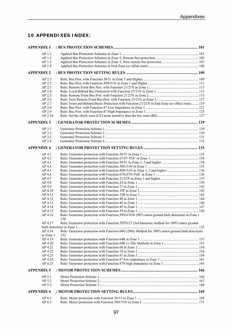
Appendixes
1100 AAPPPPEENNDDIIXXEESS IINNDDEEXX::
APPENDIX 1 : BUS PROTECTION SCHEMES...................................................................................... 101 AP 1.1 Applied Bus Protection Schemes in Zone 1 ...................................................................................... 101 AP 1.2 Applied Bus Protection Schemes in Zone 2; Remote bus protection................................................. 105 AP 1.3 Applied Bus Protection Schemes in Zone 3; Next remote bus protection ......................................... 107 AP 1.4 Applied Bus Protection Schemes in End-Zone (or offset zone) ........................................................ 108
APPENDIX 2 : BUS PROTECTION SETTING RULES ......................................................................... 109 AP 2.1 Rule: Bus Prot. with Function 50/51 in Zone 1 and Higher............................................................... 109 AP 2.2 Rule: Bus Prot. with Function 50N/51N in Zone 1 and Higher......................................................... 111 AP 2.3 Rule: Remote Front Bus Prot. with Function 21/21N in Zone 1........................................................ 113 AP 2.4 Rule: Local Behind Bus Protection with Function 21/21N in Zone 1 ............................................... 113 AP 2.5 Rule: Remote Front Bus Prot. with Function 21/21N in Zone 2........................................................ 115 AP 2.6 Rule: Next Remote Front Bus Prot. with Function 21/21N in Zone 3............................................... 117 AP 2.7 Rule: Front and Behind Buses Protection with Function 21/21N in End-Zone (or offset zone)........ 119 AP 2.8 Rule: Bus Prot. with Function 87 Low Impedance in Zone 1............................................................ 121 AP 2.9 Rule: Bus Prot. with Function 87 High Impedance in Zone 1 ........................................................... 125 AP 2.10 Rule: Set the check zone (CZ) more sensitive than the bus zone (BZ).............................................. 127
APPENDIX 3 : GENERATOR PROTECTION SCHEMES.................................................................... 129 AP 3.1 Generator Protection Scheme 1 ......................................................................................................... 129 AP 3.2 Generator Protection Scheme 2 ......................................................................................................... 130 AP 3.3 Generator Protection Scheme 3 ......................................................................................................... 131 AP 3.4 Generator Protection Scheme 4 ......................................................................................................... 132
APPENDIX 4 : GENERATOR PROTECTION SETTING RULES ....................................................... 133 AP 4.1 Rule: Generator protection with Function 50/51 in Zone 1 ............................................................... 133 AP 4.2 Rule: Generator protection with Function 67/67-TOC in Zone 1...................................................... 134 AP 4.3 Rule: Generator protection with Function 50/51 in Zone 1, 2 and higher ......................................... 134 AP 4.4 Rule: Generator protection with Function 50N/51N in Zone 1 ......................................................... 135 AP 4.5 Rule: Generator protection with Function 50N/51N in Zone 1, 2 and higher.................................... 136 AP 4.6 Rule: Generator protection with Function 67N/67N-TOC in Zone 1 ................................................ 136 AP 4.7 Rule: Generator protection with Function 21/21N in Zone 1 and higher .......................................... 137 AP 4.8 Rule: Generator protection with Function 24 in Zone 1 .................................................................... 139 AP 4.9 Rule: Generator protection with Function 27 in Zone 1 .................................................................... 142 AP 4.10 Rule: Generator protection with Function 32F in Zone 1 .................................................................. 142 AP 4.11 Rule: Generator protection with Function 32R in Zone 1.................................................................. 143 AP 4.12 Rule: Generator protection with Function 40 in Zone 1 .................................................................... 144 AP 4.13 Rule: Generator protection with Function 46 in Zone 1 .................................................................... 146 AP 4.14 Rule: Generator protection with Function 49 in Zone 1 .................................................................... 147 AP 4.15 Rule: Generator protection with Function 59 in Zone 1 .................................................................... 150 AP 4.16 Rule: Generator protection with Function 59N/67GN (90% stator ground fault detection) in Zone 1 150 AP 4.17 Rule: Generator protection with Function 59TN/27 (3rd harmonic method for 100% stator ground fault detection) in Zone 1........................................................................................................................................ 152 AP 4.18 Rule: Generator protection with Function 64G (20Hz Method for 100% stator ground fault detection) in Zone 1 153 AP 4.19 Rule: Generator protection with Function 64R in Zone 1.................................................................. 153 AP 4.20 Rule: Generator protection with Function 64R (1-3Hz Method) in Zone 1....................................... 153 AP 4.21 Rule: Generator protection with Function 68 in Zone 1 .................................................................... 154 AP 4.22 Rule: Generator protection with Function 78 in Zone 1 .................................................................... 156 AP 4.23 Rule: Generator protection with Function 81 in Zone 1 .................................................................... 158 AP 4.24 Rule: Generator protection with Function 87 low impedance in Zone 1 ........................................... 161 AP 4.25 Rule: Generator protection with Function 87N high impedance in Zone 1 ....................................... 165
APPENDIX 5 : MOTOR PROTECTION SCHEMES.............................................................................. 166 AP 5.1 Motor Protection Scheme 1 ............................................................................................................... 166 AP 5.2 Motor Protection Scheme 2 ............................................................................................................... 167 AP 5.3 Motor Protection Scheme 3 ............................................................................................................... 168
APPENDIX 6 : MOTOR PROTECTION SETTING RULES.................................................................. 169 AP 6.1 Rule: Motor protection with Function 50/51 in Zone 1 ..................................................................... 169 AP 6.2 Rule: Motor protection with Function 50N/51N in Zone 1 ............................................................... 171
97
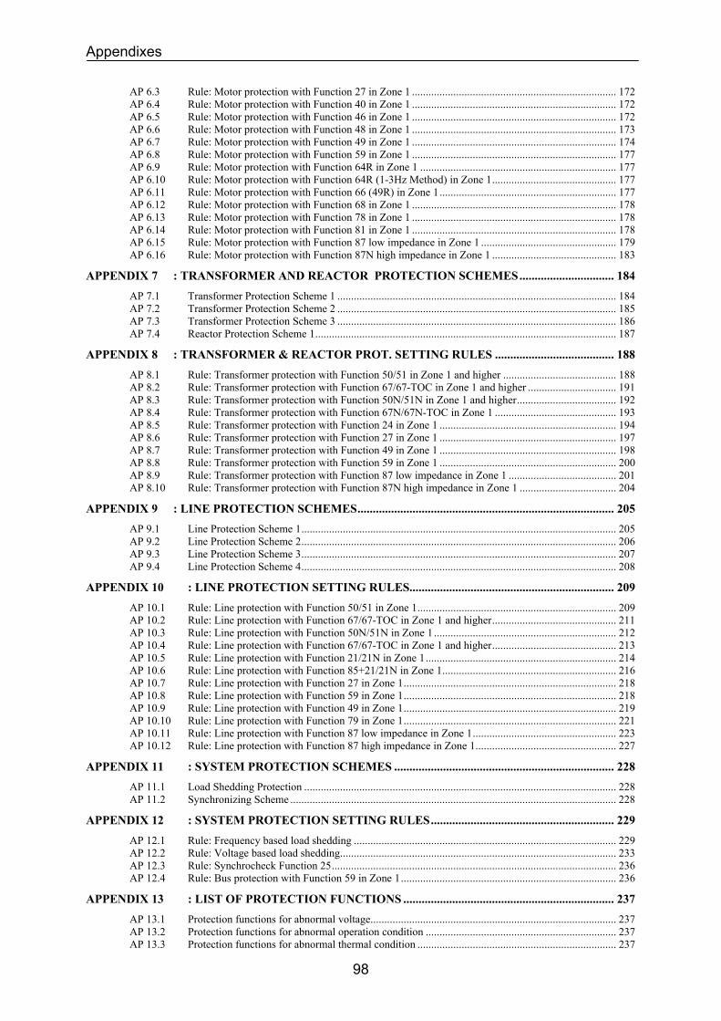
Appendixes
AP 6.3 Rule: Motor protection with Function 27 in Zone 1 .......................................................................... 172 AP 6.4 Rule: Motor protection with Function 40 in Zone 1 .......................................................................... 172 AP 6.5 Rule: Motor protection with Function 46 in Zone 1 .......................................................................... 172 AP 6.6 Rule: Motor protection with Function 48 in Zone 1 .......................................................................... 173 AP 6.7 Rule: Motor protection with Function 49 in Zone 1 .......................................................................... 174 AP 6.8 Rule: Motor protection with Function 59 in Zone 1 .......................................................................... 177 AP 6.9 Rule: Motor protection with Function 64R in Zone 1 ....................................................................... 177 AP 6.10 Rule: Motor protection with Function 64R (1-3Hz Method) in Zone 1............................................. 177 AP 6.11 Rule: Motor protection with Function 66 (49R) in Zone 1................................................................ 177 AP 6.12 Rule: Motor protection with Function 68 in Zone 1 .......................................................................... 178 AP 6.13 Rule: Motor protection with Function 78 in Zone 1 .......................................................................... 178 AP 6.14 Rule: Motor protection with Function 81 in Zone 1 .......................................................................... 178 AP 6.15 Rule: Motor protection with Function 87 low impedance in Zone 1 ................................................. 179 AP 6.16 Rule: Motor protection with Function 87N high impedance in Zone 1 ............................................. 183
APPENDIX 7 : TRANSFORMER AND REACTOR PROTECTION SCHEMES............................... 184 AP 7.1 Transformer Protection Scheme 1 ..................................................................................................... 184 AP 7.2 Transformer Protection Scheme 2 ..................................................................................................... 185 AP 7.3 Transformer Protection Scheme 3 ..................................................................................................... 186 AP 7.4 Reactor Protection Scheme 1............................................................................................................. 187
APPENDIX 8 : TRANSFORMER & REACTOR PROT. SETTING RULES ....................................... 188 AP 8.1 Rule: Transformer protection with Function 50/51 in Zone 1 and higher ......................................... 188 AP 8.2 Rule: Transformer protection with Function 67/67-TOC in Zone 1 and higher ................................ 191 AP 8.3 Rule: Transformer protection with Function 50N/51N in Zone 1 and higher.................................... 192 AP 8.4 Rule: Transformer protection with Function 67N/67N-TOC in Zone 1 ............................................ 193 AP 8.5 Rule: Transformer protection with Function 24 in Zone 1 ................................................................ 194 AP 8.6 Rule: Transformer protection with Function 27 in Zone 1 ................................................................ 197 AP 8.7 Rule: Transformer protection with Function 49 in Zone 1 ................................................................ 198 AP 8.8 Rule: Transformer protection with Function 59 in Zone 1 ................................................................ 200 AP 8.9 Rule: Transformer protection with Function 87 low impedance in Zone 1 ....................................... 201 AP 8.10 Rule: Transformer protection with Function 87N high impedance in Zone 1 ................................... 204
APPENDIX 9 : LINE PROTECTION SCHEMES.................................................................................... 205 AP 9.1 Line Protection Scheme 1.................................................................................................................. 205 AP 9.2 Line Protection Scheme 2.................................................................................................................. 206 AP 9.3 Line Protection Scheme 3.................................................................................................................. 207 AP 9.4 Line Protection Scheme 4.................................................................................................................. 208
APPENDIX 10 : LINE PROTECTION SETTING RULES................................................................... 209 AP 10.1 Rule: Line protection with Function 50/51 in Zone 1........................................................................ 209 AP 10.2 Rule: Line protection with Function 67/67-TOC in Zone 1 and higher............................................. 211 AP 10.3 Rule: Line protection with Function 50N/51N in Zone 1 .................................................................. 212 AP 10.4 Rule: Line protection with Function 67/67-TOC in Zone 1 and higher............................................. 213 AP 10.5 Rule: Line protection with Function 21/21N in Zone 1..................................................................... 214 AP 10.6 Rule: Line protection with Function 85+21/21N in Zone 1............................................................... 216 AP 10.7 Rule: Line protection with Function 27 in Zone 1............................................................................. 218 AP 10.8 Rule: Line protection with Function 59 in Zone 1............................................................................. 218 AP 10.9 Rule: Line protection with Function 49 in Zone 1............................................................................. 219 AP 10.10 Rule: Line protection with Function 79 in Zone 1............................................................................. 221 AP 10.11 Rule: Line protection with Function 87 low impedance in Zone 1.................................................... 223 AP 10.12 Rule: Line protection with Function 87 high impedance in Zone 1................................................... 227
APPENDIX 11 : SYSTEM PROTECTION SCHEMES ........................................................................ 228 AP 11.1 Load Shedding Protection ................................................................................................................. 228 AP 11.2 Synchronizing Scheme ...................................................................................................................... 228
APPENDIX 12 : SYSTEM PROTECTION SETTING RULES............................................................ 229 AP 12.1 Rule: Frequency based load shedding ............................................................................................... 229 AP 12.2 Rule: Voltage based load shedding.................................................................................................... 233 AP 12.3 Rule: Synchrocheck Function 25....................................................................................................... 236 AP 12.4 Rule: Bus protection with Function 59 in Zone 1.............................................................................. 236
APPENDIX 13 : LIST OF PROTECTION FUNCTIONS ..................................................................... 237 AP 13.1 Protection functions for abnormal voltage......................................................................................... 237 AP 13.2 Protection functions for abnormal operation condition ..................................................................... 237 AP 13.3 Protection functions for abnormal thermal condition ........................................................................ 237
98
Appendixes
AP 13.4 Protection functions for abnormal phase current ............................................................................... 238 AP 13.5 Protection functions for abnormal ground current............................................................................. 238 AP 13.6 Protection functions for abnormal phase impedance ......................................................................... 239 AP 13.7 Protection functions for abnormal ground impedance....................................................................... 239 AP 13.8 Protection functions for abnormal frequency .................................................................................... 239 AP 13.9 Protection functions for abnormal differential phase current............................................................. 240 AP 13.10 Protection functions for abnormal differential ground current .......................................................... 240 AP 13.11 Other protection function. ................................................................................................................. 240
99

Appendixes
100
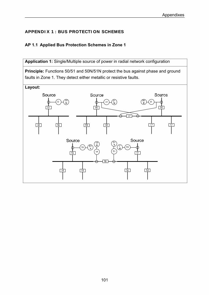
Appendixes
AAPPPPEENNDDIIXX 11 :: BBUUSS PPRROOTTEECCTTIIOONN SSCCHHEEMMEESS
AP 1.1 Applied Bus Protection Schemes in Zone 1
Application 1: Single/Multiple source of power in radial network configuration
Principle: Functions 50/51 and 50N/51N protect the bus against phase and ground faults in Zone 1. They detect either metallic or resistive faults.
Layout:
101
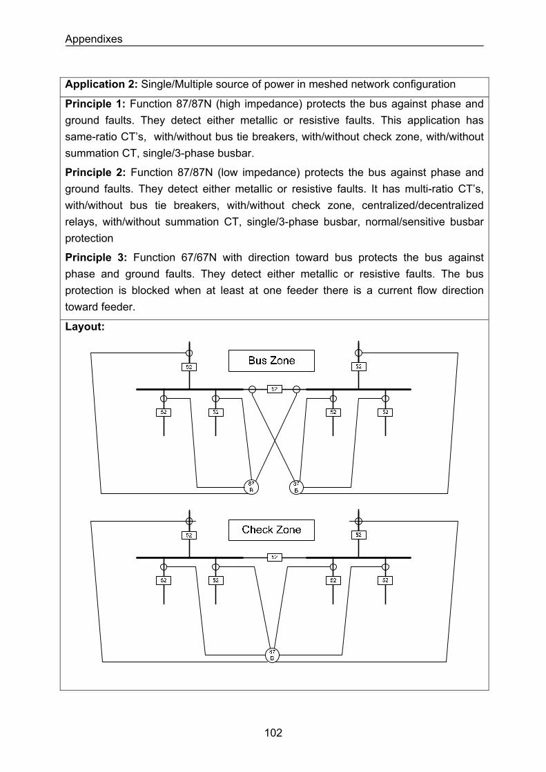
Appendixes
Application 2: Single/Multiple source of power in meshed network configuration
Principle 1: Function 87/87N (high impedance) protects the bus against phase and ground faults. They detect either metallic or resistive faults. This application has same-ratio CT’s, with/without bus tie breakers, with/without check zone, with/without summation CT, single/3-phase busbar.
Principle 2: Function 87/87N (low impedance) protects the bus against phase and ground faults. They detect either metallic or resistive faults. It has multi-ratio CT’s, with/without bus tie breakers, with/without check zone, centralized/decentralized relays, with/without summation CT, single/3-phase busbar, normal/sensitive busbar protection
Principle 3: Function 67/67N with direction toward bus protects the bus against phase and ground faults. They detect either metallic or resistive faults. The bus protection is blocked when at least at one feeder there is a current flow direction toward feeder.
Layout:
102
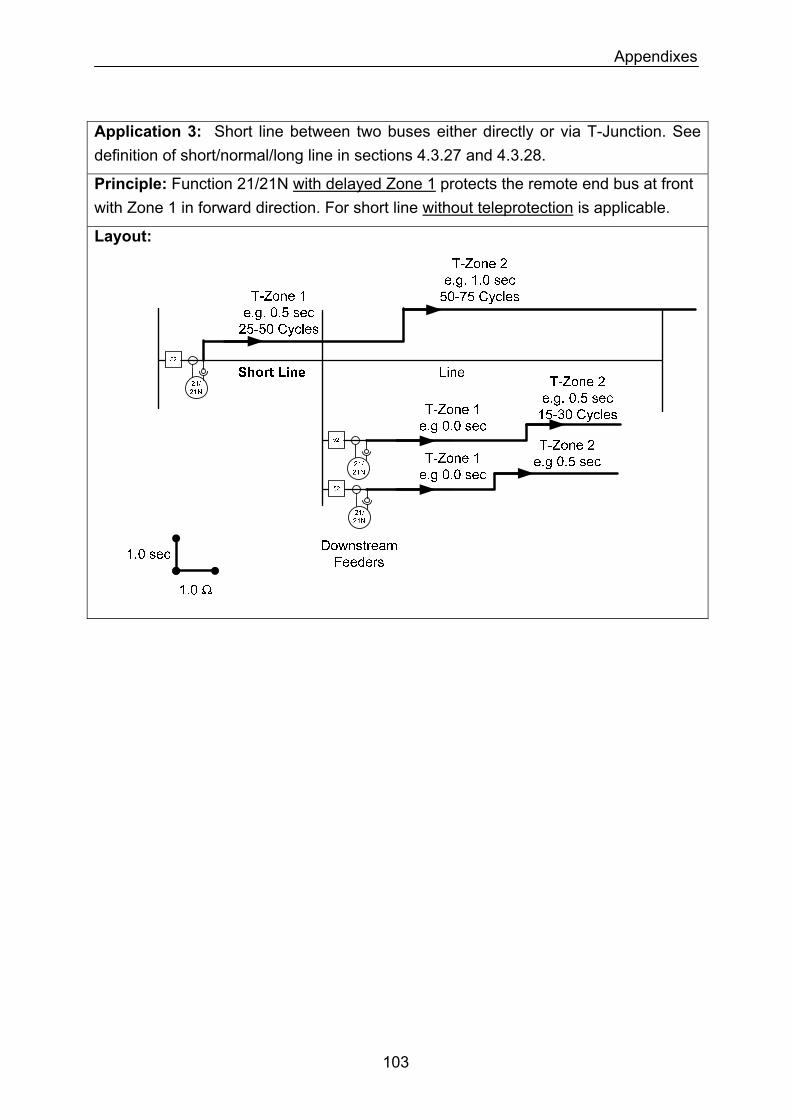
Appendixes
Application 3: Short line between two buses either directly or via T-Junction. See definition of short/normal/long line in sections 4.3.27 and 4.3.28.
Principle: Function 21/21N with delayed Zone 1 protects the remote end bus at front with Zone 1 in forward direction. For short line without teleprotection is applicable.
Layout:
103
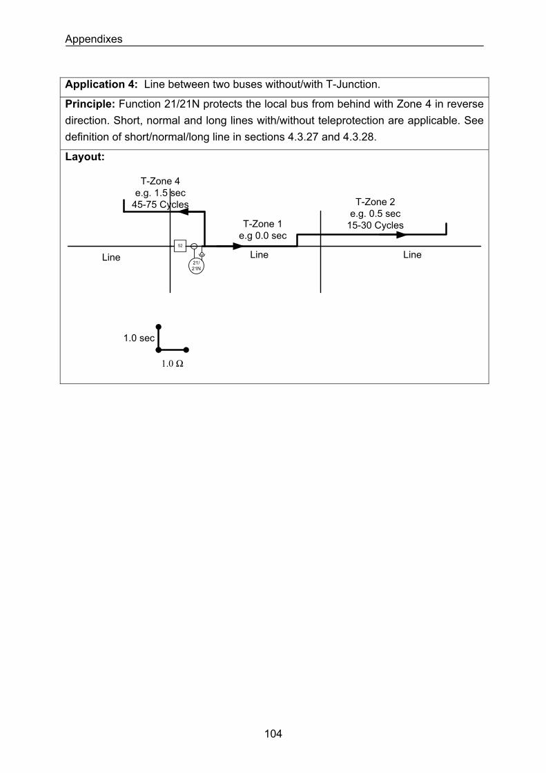
Appendixes
Application 4: Line between two buses without/with T-Junction.
Principle: Function 21/21N protects the local bus from behind with Zone 4 in reverse direction. Short, normal and long lines with/without teleprotection are applicable. See definition of short/normal/long line in sections 4.3.27 and 4.3.28.
Layout:
T-Zone 1 e.g 0.0 sec
T-Zone 2 e.g. 0.5 sec
15-30 Cycles
Line Line52
21/21N
1.0 sec
1.0 Ω
T-Zone 4 e.g. 1.5 sec
45-75 Cycles
Line
104
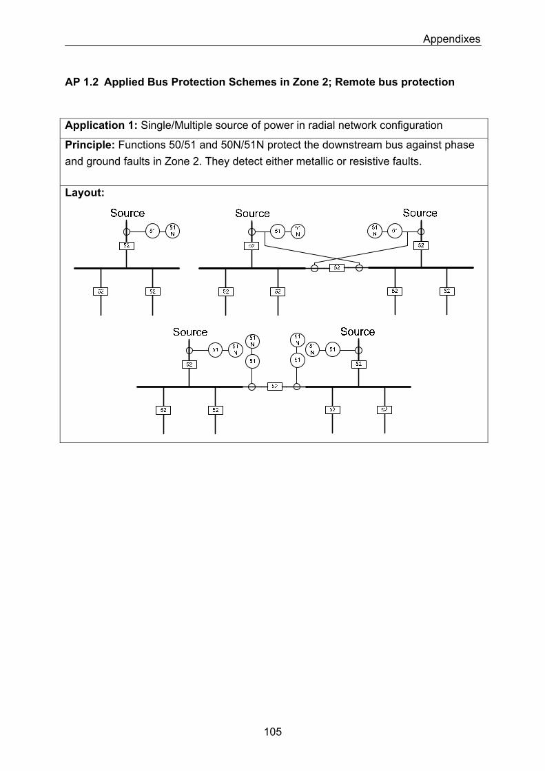
Appendixes
AP 1.2 Applied Bus Protection Schemes in Zone 2; Remote bus protection
Application 1: Single/Multiple source of power in radial network configuration
Principle: Functions 50/51 and 50N/51N protect the downstream bus against phase and ground faults in Zone 2. They detect either metallic or resistive faults.
Layout:
105
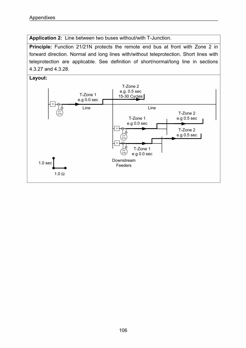
Appendixes
Application 2: Line between two buses without/with T-Junction.
Principle: Function 21/21N protects the remote end bus at front with Zone 2 in forward direction. Normal and long lines with/without teleprotection. Short lines with teleprotection are applicable. See definition of short/normal/long line in sections 4.3.27 and 4.3.28.
Layout:
1.0 sec
1.0 Ω
Downstream Feeders
T-Zone 1 e.g 0.0 sec
T-Zone 2 e.g. 0.5 sec
15-30 Cycles
T-Zone 1 e.g 0.0 sec
T-Zone 2 e.g 0.5 sec
T-Zone 1 e.g 0.0 sec
T-Zone 2 e.g 0.5 sec
Line Line52
21/21N
52
21/21N
52
21/21N
106
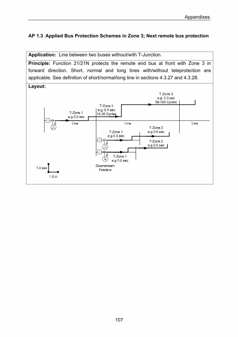
Appendixes
AP 1.3 Applied Bus Protection Schemes in Zone 3; Next remote bus protection
Application: Line between two buses without/with T-Junction.
Principle: Function 21/21N protects the remote end bus at front with Zone 3 in forward direction. Short, normal and long lines with/without teleprotection are applicable. See definition of short/normal/long line in sections 4.3.27 and 4.3.28.
Layout:
107
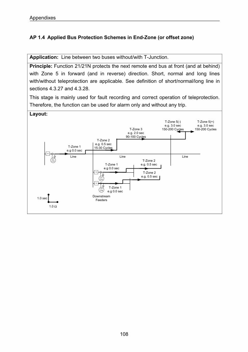
Appendixes
AP 1.4 Applied Bus Protection Schemes in End-Zone (or offset zone)
Application: Line between two buses without/with T-Junction.
Principle: Function 21/21N protects the next remote end bus at front (and at behind) with Zone 5 in forward (and in reverse) direction. Short, normal and long lines with/without teleprotection are applicable. See definition of short/normal/long line in sections 4.3.27 and 4.3.28.
This stage is mainly used for fault recording and correct operation of teleprotection. Therefore, the function can be used for alarm only and without any trip.
Layout:
1.0 sec
1.0 Ω
Downstream Feeders
T-Zone 1 e.g 0.0 sec
T-Zone 2e.g. 0.5 sec
15-30 Cycles
T-Zone 1 e.g 0.0 sec
T-Zone 2 e.g. 0.5 sec
T-Zone 1 e.g 0.0 sec
T-Zone 2 e.g. 0.5 sec
Line Line52
21/21N
52
21/21N
52
21/21N
Line
T-Zone 3 e.g. 2.0 sec
90-100 Cycles
T-Zone 5(+) e.g. 3.0 sec
150-200 Cycles
T-Zone 5(-) e.g. 3.0 sec
150-200 Cycles
108
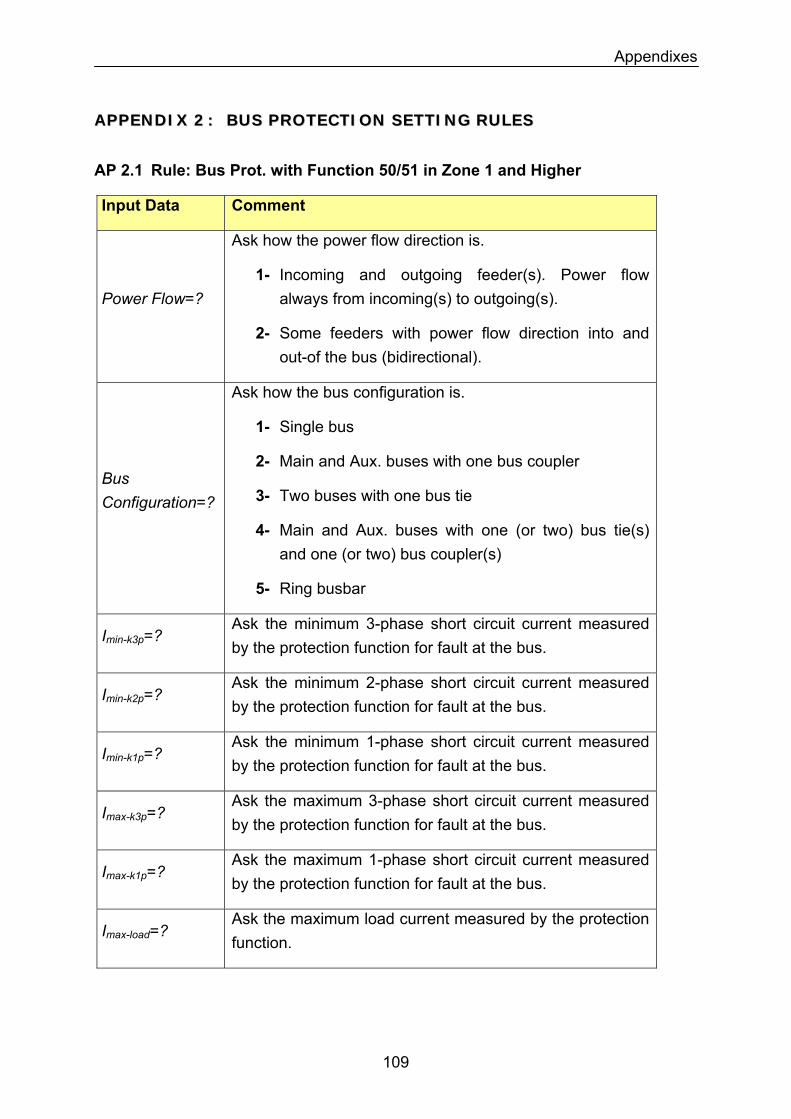
Appendixes
AAPPPPEENNDDIIXX 22 :: BBUUSS PPRROOTTEECCTTIIOONN SSEETTTTIINNGG RRUULLEESS
AP 2.1 Rule: Bus Prot. with Function 50/51 in Zone 1 and Higher
Input Data Comment
Power Flow=?
Ask how the power flow direction is.
1- Incoming and outgoing feeder(s). Power flow always from incoming(s) to outgoing(s).
2- Some feeders with power flow direction into and out-of the bus (bidirectional).
Ask how the bus configuration is.
1- Single bus
2- Main and Aux. buses with one bus coupler Bus Configuration=? 3- Two buses with one bus tie
4- Main and Aux. buses with one (or two) bus tie(s) and one (or two) bus coupler(s)
5- Ring busbar
Ask the minimum 3-phase short circuit current measured by the protection function for fault at the bus.
Imin-k3p=?
Ask the minimum 2-phase short circuit current measured by the protection function for fault at the bus.
Imin-k2p=?
Ask the minimum 1-phase short circuit current measured by the protection function for fault at the bus.
Imin-k1p=?
Ask the maximum 3-phase short circuit current measured by the protection function for fault at the bus.
Imax-k3p=?
Imax-k1p=? Ask the maximum 1-phase short circuit current measured by the protection function for fault at the bus.
Imax-load=? Ask the maximum load current measured by the protection function.
109
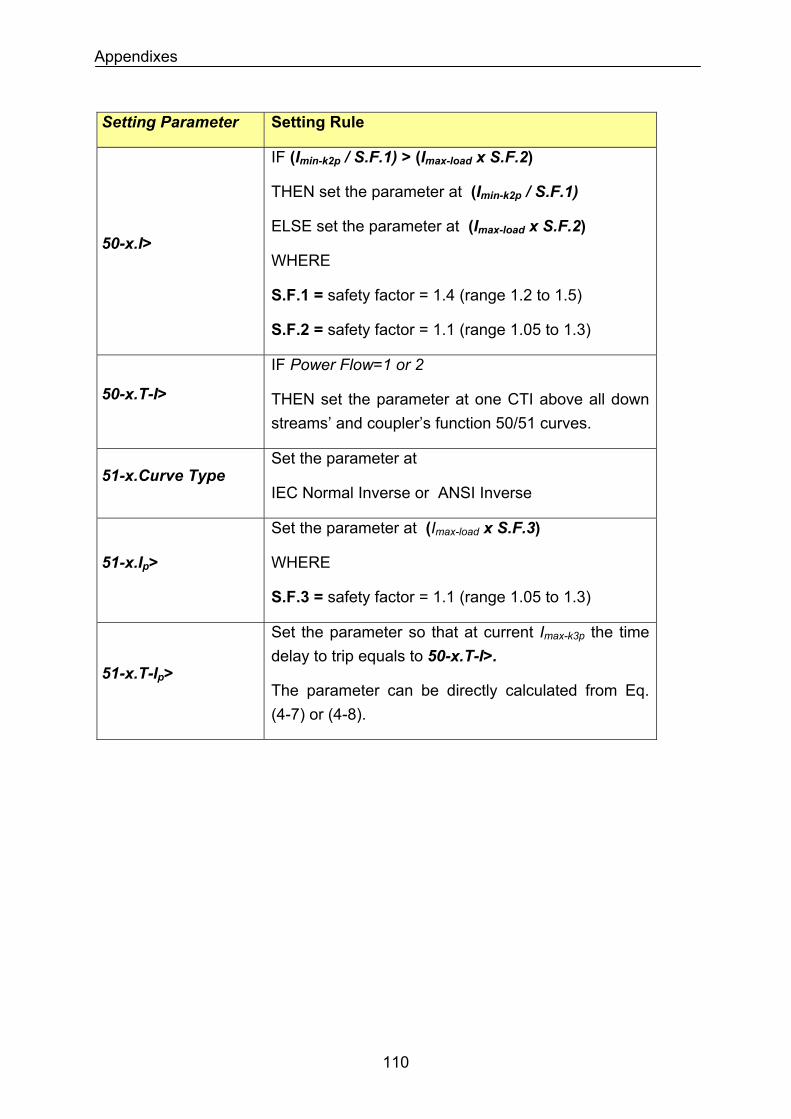
Appendixes
Setting Parameter Setting Rule
IF (Imin-k2p / S.F.1) > (Imax-load x S.F.2)
THEN set the parameter at (Imin-k2p / S.F.1)
ELSE set the parameter at (Imax-load x S.F.2) 50-x.I>
WHERE
S.F.1 = safety factor = 1.4 (range 1.2 to 1.5)
S.F.2 = safety factor = 1.1 (range 1.05 to 1.3)
50-x.T-I>
IF Power Flow=1 or 2
THEN set the parameter at one CTI above all down streams’ and coupler’s function 50/51 curves.
51-x.Curve Type Set the parameter at
IEC Normal Inverse or ANSI Inverse
51-x.Ip>
Set the parameter at (Imax-load x S.F.3)
WHERE
S.F.3 = safety factor = 1.1 (range 1.05 to 1.3)
Set the parameter so that at current Imax-k3p the time delay to trip equals to 50-x.T-I>.
51-x.T-Ip> The parameter can be directly calculated from Eq. (4-7) or (4-8).
110
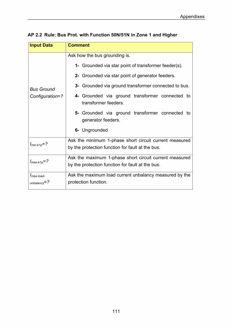
Appendixes
AP 2.2 Rule: Bus Prot. with Function 50N/51N in Zone 1 and Higher
Input Data Comment
Bus Ground Configuration=?
Ask how the bus grounding is.
1- Grounded via star point of transformer feeder(s).
2- Grounded via star point of generator feeders.
3- Grounded via ground transformer connected to bus.
4- Grounded via ground transformer connected to transformer feeders.
5- Grounded via ground transformer connected to generator feeders.
6- Ungrounded
Ask the minimum 1-phase short circuit current measured by the protection function for fault at the bus.
Imin-k1p=?
Ask the maximum 1-phase short circuit current measured by the protection function for fault at the bus.
Imax-k1p=?
Imax-load-
unbalancy=? Ask the maximum load current unbalancy measured by the protection function.
111
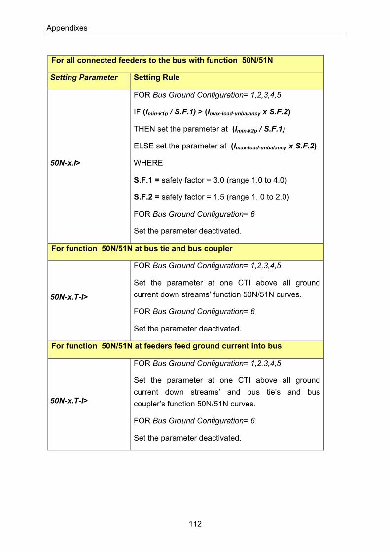
Appendixes
For all connected feeders to the bus with function 50N/51N
Setting Parameter Setting Rule
50N-x.I>
FOR Bus Ground Configuration= 1,2,3,4,5
IF (Imin-k1p / S.F.1) > (Imax-load-unbalancy x S.F.2)
THEN set the parameter at (Imin-k2p / S.F.1)
ELSE set the parameter at (Imax-load-unbalancy x S.F.2)
WHERE
S.F.1 = safety factor = 3.0 (range 1.0 to 4.0)
S.F.2 = safety factor = 1.5 (range 1. 0 to 2.0)
FOR Bus Ground Configuration= 6
Set the parameter deactivated.
For function 50N/51N at bus tie and bus coupler
FOR Bus Ground Configuration= 1,2,3,4,5
Set the parameter at one CTI above all ground current down streams’ function 50N/51N curves.
FOR Bus Ground Configuration= 6
Set the parameter deactivated.
50N-x.T-I>
For function 50N/51N at feeders feed ground current into bus
FOR Bus Ground Configuration= 1,2,3,4,5
Set the parameter at one CTI above all ground current down streams’ and bus tie’s and bus coupler’s function 50N/51N curves. 50N-x.T-I>
FOR Bus Ground Configuration= 6
Set the parameter deactivated.
112
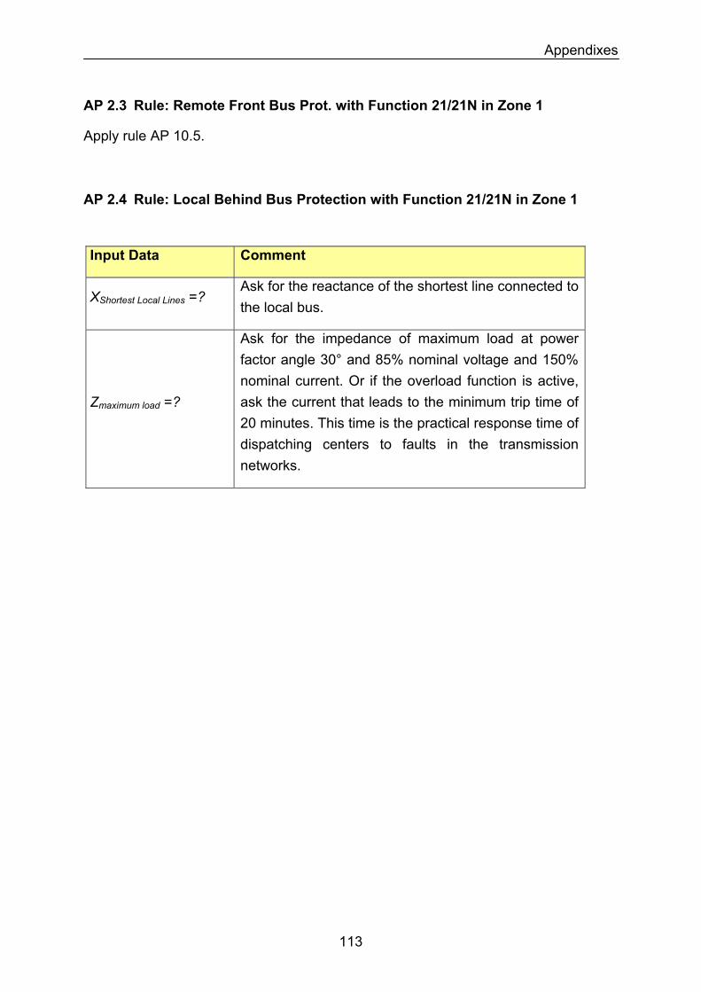
Appendixes
AP 2.3 Rule: Remote Front Bus Prot. with Function 21/21N in Zone 1
Apply rule AP 10.5.
AP 2.4 Rule: Local Behind Bus Protection with Function 21/21N in Zone 1
Input Data Comment
Ask for the reactance of the shortest line connected to the local bus.
XShortest Local Lines =?
Zmaximum load =?
Ask for the impedance of maximum load at power factor angle 30° and 85% nominal voltage and 150% nominal current. Or if the overload function is active, ask the current that leads to the minimum trip time of 20 minutes. This time is the practical response time of dispatching centers to faults in the transmission networks.
113
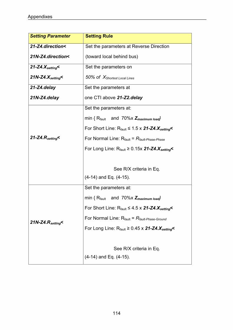
Appendixes
Setting Parameter Setting Rule
21-Z4.direction<
21N-Z4.direction<
Set the parameters at Reverse Direction
(toward local behind bus)
21-Z4.Xsetting<
21N-Z4.Xsetting<
Set the parameters on
50% of XShortest Local Lines
21-Z4.delay
21N-Z4.delay
Set the parameters at
one CTI above 21-Z2.delay
21-Z4.Rsetting<
Set the parameters at:
min Rfault and 70%x Zmaximum load
For Short Line: Rfault ≤ 1.5 x 21-Z4.Xsetting<
For Normal Line: Rfault = Rfault-Phase-Phase
For Long Line: Rfault ≥ 0.15x 21-Z4.Xsetting<
See R/X criteria in Eq.
(4-14) and Eq. (4-15).
Set the parameters at:
min Rfault and 70%x Zmaximum load
For Short Line: Rfault ≤ 4.5 x 21-Z4.Xsetting<
For Normal Line: Rfault = Rfault-Phase-Ground 21N-Z4.Rsetting<
For Long Line: Rfault ≥ 0.45 x 21-Z4.Xsetting<
See R/X criteria in Eq.
(4-14) and Eq. (4-15).
114
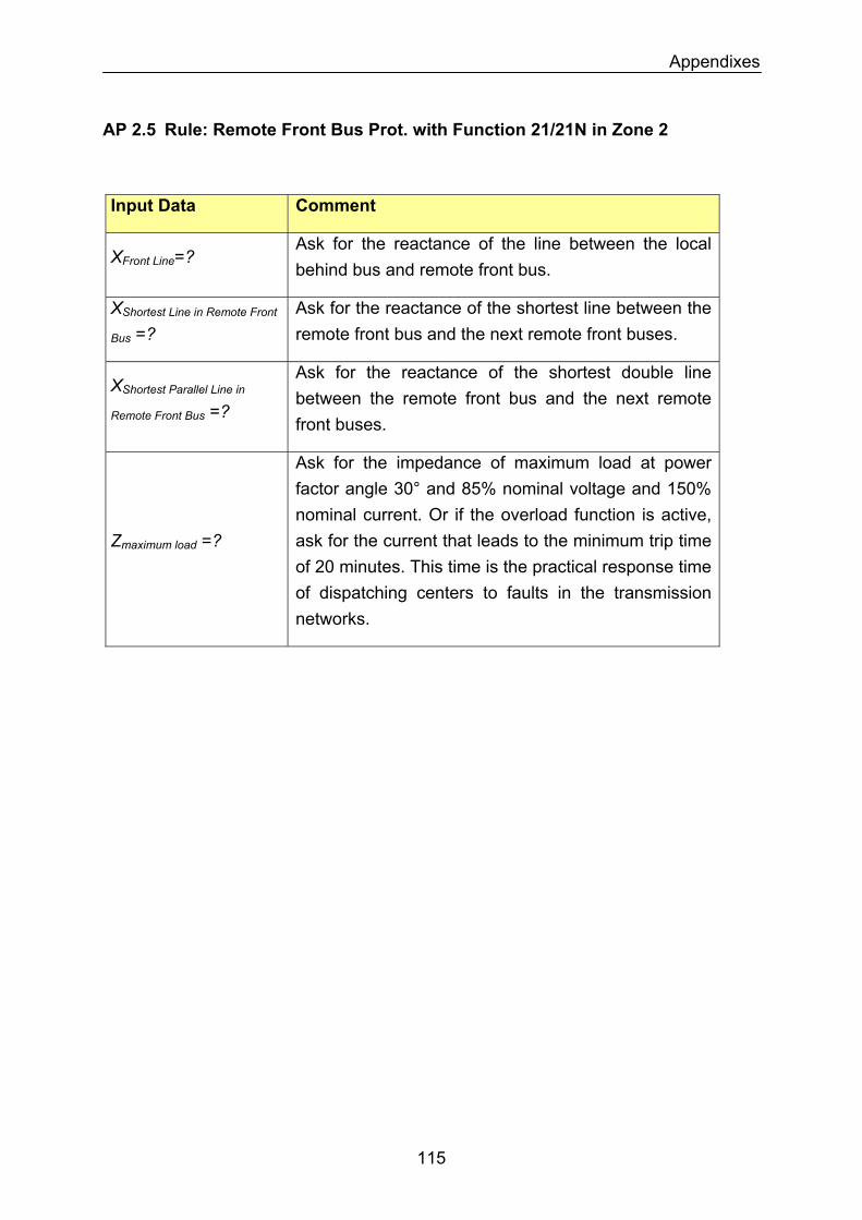
Appendixes
AP 2.5 Rule: Remote Front Bus Prot. with Function 21/21N in Zone 2
Input Data Comment
XFront Line=? Ask for the reactance of the line between the local behind bus and remote front bus.
Ask for the reactance of the shortest line between the remote front bus and the next remote front buses.
XShortest Line in Remote Front
Bus =?
Ask for the reactance of the shortest double line between the remote front bus and the next remote front buses.
XShortest Parallel Line in
Remote Front Bus =?
Zmaximum load =?
Ask for the impedance of maximum load at power factor angle 30° and 85% nominal voltage and 150% nominal current. Or if the overload function is active, ask for the current that leads to the minimum trip time of 20 minutes. This time is the practical response time of dispatching centers to faults in the transmission networks.
115
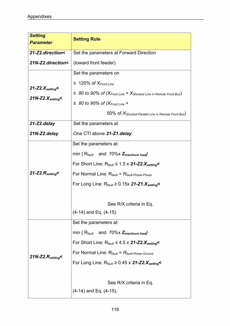
Appendixes
Setting Parameter
Setting Rule
21-Z2.direction<
21N-Z2.direction<
Set the parameters at Forward Direction
(toward front feeder)
21-Z2.Xsetting<
21N-Z2.Xsetting<
Set the parameters on
≥ 120% of XFront Line
≤ 80 to 90% of (XFront Line + XShortest Line in Remote Front Bus)
≤ 80 to 90% of (XFront Line +
50% of XShortest Parallel Line in Remote Front Bus)
21-Z2.delay
21N-Z2.delay
Set the parameters at
One CTI above 21-Z1.delay.
21-Z2.Rsetting<
Set the parameters at:
min Rfault and 70%x Zmaximum load
For Short Line: Rfault ≤ 1.5 x 21-Z2.Xsetting<
For Normal Line: Rfault = Rfault-Phase-Phase
For Long Line: Rfault ≥ 0.15x 21-Z1.Xsetting<
See R/X criteria in Eq.
(4-14) and Eq. (4-15).
Set the parameters at:
min Rfault and 70%x Zmaximum load
For Short Line: Rfault ≤ 4.5 x 21-Z2.Xsetting<
For Normal Line: Rfault = Rfault-Phase-Ground
For Long Line: Rfault ≥ 0.45 x 21-Z2.Xsetting<
21N-Z2.Rsetting<
See R/X criteria in Eq.
(4-14) and Eq. (4-15).
116
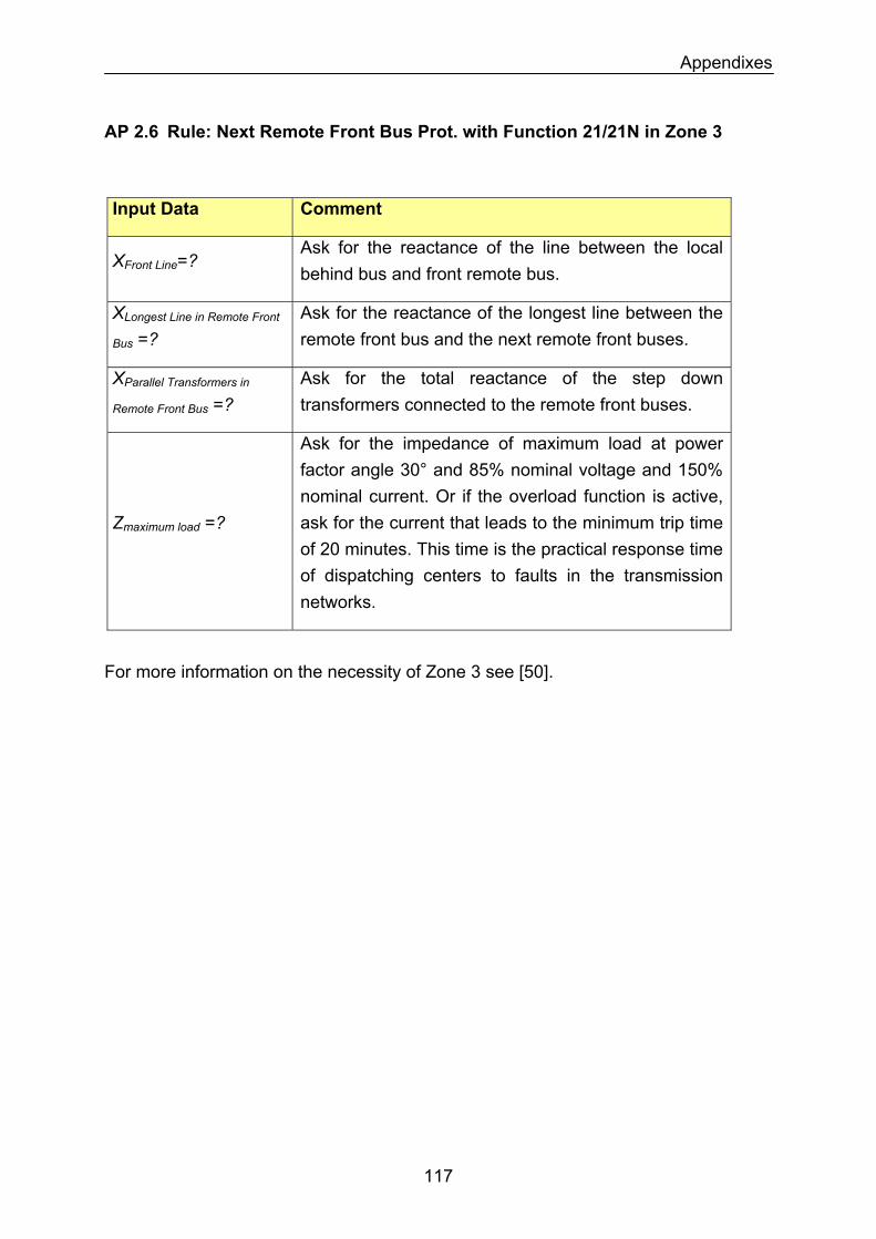
Appendixes
AP 2.6 Rule: Next Remote Front Bus Prot. with Function 21/21N in Zone 3
Input Data Comment
Ask for the reactance of the line between the local behind bus and front remote bus.
XFront Line=?
Ask for the reactance of the longest line between the remote front bus and the next remote front buses.
XLongest Line in Remote Front
Bus =?
XParallel Transformers in
Remote Front Bus =? Ask for the total reactance of the step down transformers connected to the remote front buses.
Zmaximum load =?
Ask for the impedance of maximum load at power factor angle 30° and 85% nominal voltage and 150% nominal current. Or if the overload function is active, ask for the current that leads to the minimum trip time of 20 minutes. This time is the practical response time of dispatching centers to faults in the transmission networks.
For more information on the necessity of Zone 3 see [50].
117
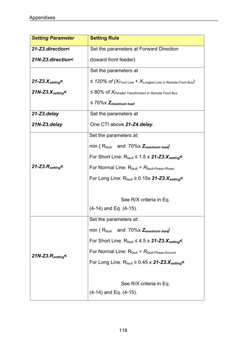
Appendixes
Setting Parameter Setting Rule
21-Z3.direction<
21N-Z3.direction<
Set the parameters at Forward Direction
(toward front feeder)
21-Z3.Xsetting<
21N-Z3.Xsetting<
Set the parameters at
≤ 120% of (XFront Line + XLongest Line in Remote Front Bus)
≤ 80% of XParallel Transformers in Remote Front Bus
≤ 70%x Zmaximum load
21-Z3.delay
21N-Z3.delay
Set the parameters at
One CTI above 21-Z4.delay.
21-Z3.Rsetting<
Set the parameters at:
min Rfault and 70%x Zmaximum load
For Short Line: Rfault ≤ 1.5 x 21-Z3.Xsetting<
For Normal Line: Rfault = Rfault-Phase-Phase
For Long Line: Rfault ≥ 0.15x 21-Z3.Xsetting<
See R/X criteria in Eq.
(4-14) and Eq. (4-15).
21N-Z3.Rsetting<
Set the parameters at:
min Rfault and 70%x Zmaximum load
For Short Line: Rfault ≤ 4.5 x 21-Z3.Xsetting<
For Normal Line: Rfault = Rfault-Phase-Ground
For Long Line: Rfault ≥ 0.45 x 21-Z3.Xsetting<
See R/X criteria in Eq.
(4-14) and Eq. (4-15).
118
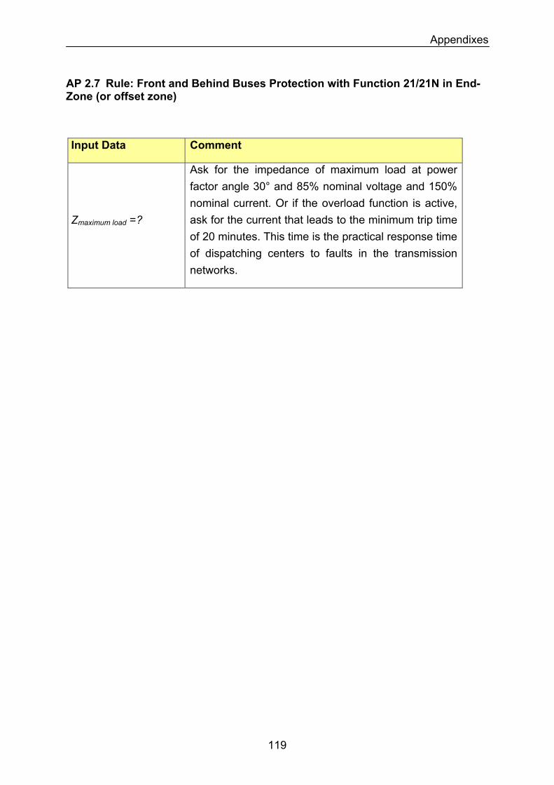
Appendixes
AP 2.7 Rule: Front and Behind Buses Protection with Function 21/21N in End-Zone (or offset zone)
Input Data Comment
Zmaximum load =?
Ask for the impedance of maximum load at power factor angle 30° and 85% nominal voltage and 150% nominal current. Or if the overload function is active, ask for the current that leads to the minimum trip time of 20 minutes. This time is the practical response time of dispatching centers to faults in the transmission networks.
119
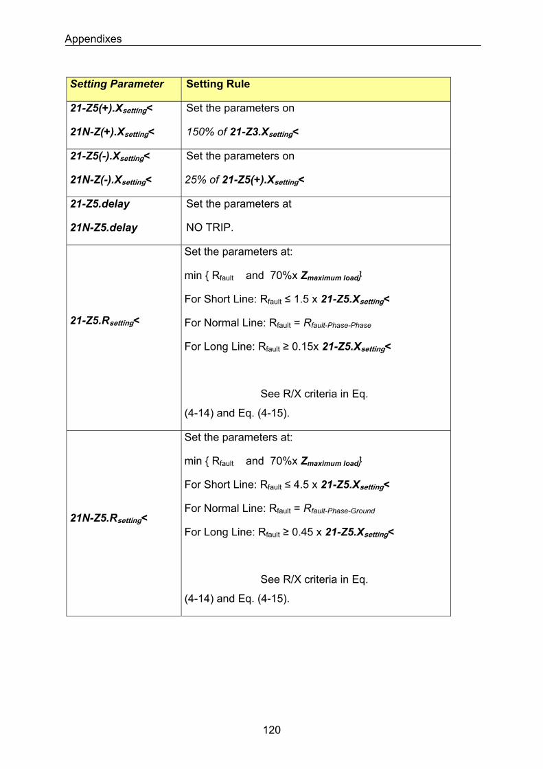
Appendixes
Setting Parameter Setting Rule
21-Z5(+).Xsetting<
21N-Z(+).Xsetting<
Set the parameters on
150% of 21-Z3.Xsetting<
21-Z5(-).Xsetting<
21N-Z(-).Xsetting<
Set the parameters on
25% of 21-Z5(+).Xsetting<
21-Z5.delay
21N-Z5.delay
Set the parameters at
NO TRIP.
21-Z5.Rsetting<
Set the parameters at:
min Rfault and 70%x Zmaximum load
For Short Line: Rfault ≤ 1.5 x 21-Z5.Xsetting<
For Normal Line: Rfault = Rfault-Phase-Phase
For Long Line: Rfault ≥ 0.15x 21-Z5.Xsetting<
See R/X criteria in Eq.
(4-14) and Eq. (4-15).
21N-Z5.Rsetting<
Set the parameters at:
min Rfault and 70%x Zmaximum load
For Short Line: Rfault ≤ 4.5 x 21-Z5.Xsetting<
For Normal Line: Rfault = Rfault-Phase-Ground
For Long Line: Rfault ≥ 0.45 x 21-Z5.Xsetting<
See R/X criteria in Eq.
(4-14) and Eq. (4-15).
120
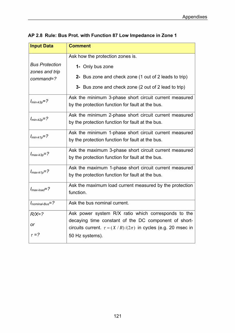
Appendixes
AP 2.8 Rule: Bus Prot. with Function 87 Low Impedance in Zone 1
Input Data Comment
Bus Protection zones and trip command=?
Ask how the protection zones is.
1- Only bus zone
2- Bus zone and check zone (1 out of 2 leads to trip)
3- Bus zone and check zone (2 out of 2 lead to trip)
Imin-k3p=? Ask the minimum 3-phase short circuit current measured by the protection function for fault at the bus.
Imin-k2p=? Ask the minimum 2-phase short circuit current measured by the protection function for fault at the bus.
Imin-k1p=? Ask the minimum 1-phase short circuit current measured by the protection function for fault at the bus.
Imax-k3p=? Ask the maximum 3-phase short circuit current measured by the protection function for fault at the bus.
Ask the maximum 1-phase short circuit current measured by the protection function for fault at the bus.
Imax-k1p=?
Imax-load=? Ask the maximum load current measured by the protection function.
Inominal-Bus=? Ask the bus nominal current.
R/X=?
or
τ =?
Ask power system R/X ratio which corresponds to the decaying time constant of the DC component of short-circuits current. )2/()/( πτ RX= in cycles (e.g. 20 msec in
50 Hz systems).
121
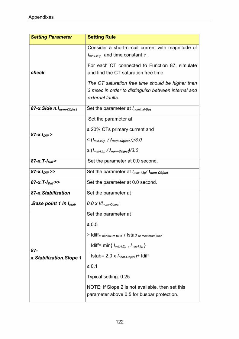
Appendixes
Setting Parameter Setting Rule
Consider a short-circuit current with magnitude of Imax-k3p and time constant τ .
check For each CT connected to Function 87, simulate and find the CT saturation free time.
The CT saturation free time should be higher than 3 msec in order to distinguish between internal and external faults.
87-x.Side n.Inom-Object Set the parameter at Inominal-Bus.
87-x.IDiff >
Set the parameter at
≥ 20% CTs primary current and
≤ (Imin-k2p / Inom-Object /)/3.0
≤ (Imin-k1p / Inom-Object)/3.0
87-x.T-IDiff > Set the parameter at 0.0 second.
87-x.IDiff >> Set the parameter at Imax-k3p/ Inom-Object
87-x.T-IDiff >> Set the parameter at 0.0 second.
87-x.Stabilization
.Base point 1 in Istab
Set the parameter at
0.0 x I/Inom-Object
87-x.Stabilization.Slope 1
Set the parameter at
≤ 0.5
≥ Idiffat minimum fault / Istab at maximum load
Idiff= min Imin-k2p , Imin-k1p
Istab= 2.0 x Inom-Object)+ Idiff
≥ 0.1
Typical setting: 0.25
NOTE: If Slope 2 is not available, then set this parameter above 0.5 for busbar protection.
122
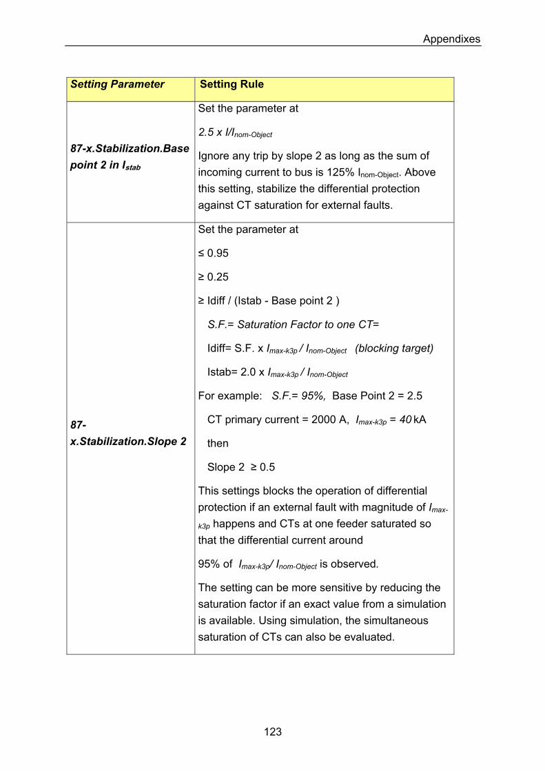
Appendixes
Setting Parameter Setting Rule
87-x.Stabilization.Base point 2 in Istab
Set the parameter at
2.5 x I/Inom-Object
Ignore any trip by slope 2 as long as the sum of incoming current to bus is 125% Inom-Object. Above this setting, stabilize the differential protection against CT saturation for external faults.
Set the parameter at
≤ 0.95
≥ 0.25
≥ Idiff / (Istab - Base point 2 )
S.F.= Saturation Factor to one CT=
Idiff= S.F. x Imax-k3p / Inom-Object (blocking target)
Istab= 2.0 x Imax-k3p / Inom-Object
For example: S.F.= 95%, Base Point 2 = 2.5
CT primary current = 2000 A, Imax-k3p = 40 kA
then
Slope 2 ≥ 0.5
This settings blocks the operation of differential protection if an external fault with magnitude of Imax-
k3p happens and CTs at one feeder saturated so that the differential current around
95% of Imax-k3p/ Inom-Object is observed.
87-x.Stabilization.Slope 2
The setting can be more sensitive by reducing the saturation factor if an exact value from a simulation is available. Using simulation, the simultaneous saturation of CTs can also be evaluated.
123
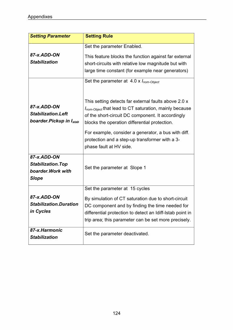
Appendixes
Setting Parameter Setting Rule
87-x.ADD-ON Stabilization
Set the parameter Enabled.
This feature blocks the function against far external short-circuits with relative low magnitude but with large time constant (for example near generators)
Set the parameter at 4.0 x Inom-Object
87-x.ADD-ON Stabilization.Left boarder.Pickup in Istab
This setting detects far external faults above 2.0 x Inom-Object that lead to CT saturation, mainly because of the short-circuit DC component. It accordingly blocks the operation differential protection.
For example, consider a generator, a bus with diff. protection and a step-up transformer with a 3-phase fault at HV side.
87-x.ADD-ON Stabilization.Top boarder.Work with Slope
Set the parameter at Slope 1
87-x.ADD-ON Stabilization.Duration in Cycles
Set the parameter at 15 cycles
By simulation of CT saturation due to short-circuit DC component and by finding the time needed for differential protection to detect an Idiff-Istab point in trip area; this parameter can be set more precisely.
87-x.Harmonic Stabilization
Set the parameter deactivated.
124
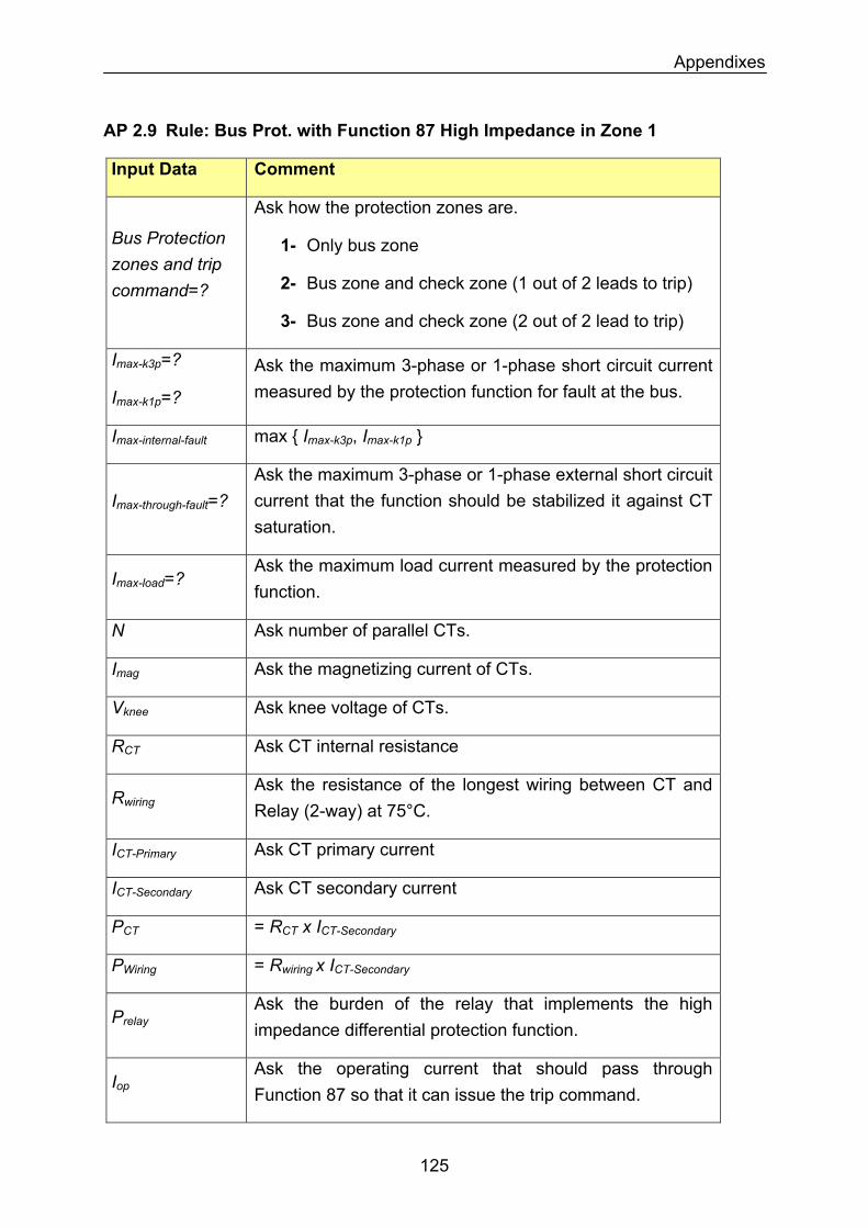
Appendixes
AP 2.9 Rule: Bus Prot. with Function 87 High Impedance in Zone 1
Input Data Comment
Ask how the protection zones are.
1- Only bus zone Bus Protection zones and trip command=? 2- Bus zone and check zone (1 out of 2 leads to trip)
3- Bus zone and check zone (2 out of 2 lead to trip)
Imax-k3p=?
Imax-k1p=?
Ask the maximum 3-phase or 1-phase short circuit current measured by the protection function for fault at the bus.
Imax-internal-fault max Imax-k3p, Imax-k1p
Imax-through-fault=? Ask the maximum 3-phase or 1-phase external short circuit current that the function should be stabilized it against CT saturation.
Imax-load=? Ask the maximum load current measured by the protection function.
N Ask number of parallel CTs.
Imag Ask the magnetizing current of CTs.
Vknee Ask knee voltage of CTs.
RCT Ask CT internal resistance
RwiringAsk the resistance of the longest wiring between CT and Relay (2-way) at 75°C.
ICT-Primary Ask CT primary current
Ask CT secondary current ICT-Secondary
PCT = RCT x ICT-Secondary
PWiring = Rwiring x ICT-Secondary
PrelayAsk the burden of the relay that implements the high impedance differential protection function.
IopAsk the operating current that should pass through Function 87 so that it can issue the trip command.
125
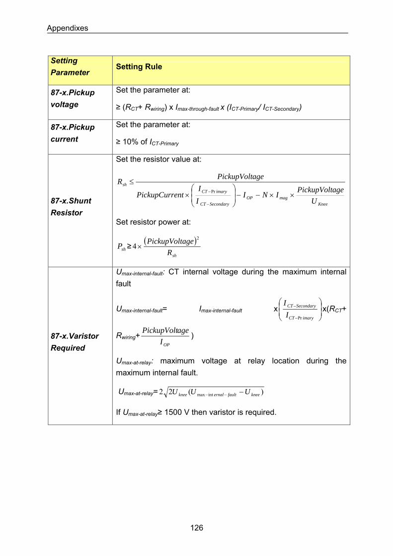
Appendixes
Setting Parameter
Setting Rule
Set the parameter at: 87-x.Pickup voltage ≥ (RCT+ Rwiring) x Imax-through-fault x (ICT-Primary/ ICT-Secondary)
87-x.Pickup current
Set the parameter at:
≥ 10% of ICT-Primary
Set the resistor value at:
KneemagOP
SecondaryCT
imaryCTsh
UagePickupVoltINI
II
entPickupCurr
agePickupVoltR
××−−⎟⎟⎠
⎞⎜⎜⎝
⎛×
≤
−
−Pr
87-x.Shunt Resistor
Set resistor power at:
shP ≥ ( )shR
agePickupVolt 2
4×
Umax-internal-fault: CT internal voltage during the maximum internal fault
Umax-internal-fault= Imax-internal-fault x ⎟⎟⎠
⎞⎜⎜⎝
⎛
−
−
imaryCT
SecondaryCT
II
Pr
x(RCT+
Rwiring+OPI
agePickupVolt ) 87-x.Varistor Required
Umax-at-relay: maximum voltage at relay location during the maximum internal fault.
Umax-at-relay= )(22 intmax kneefaulternalknee UUU −−−
If Umax-at-relay≥ 1500 V then varistor is required.
126
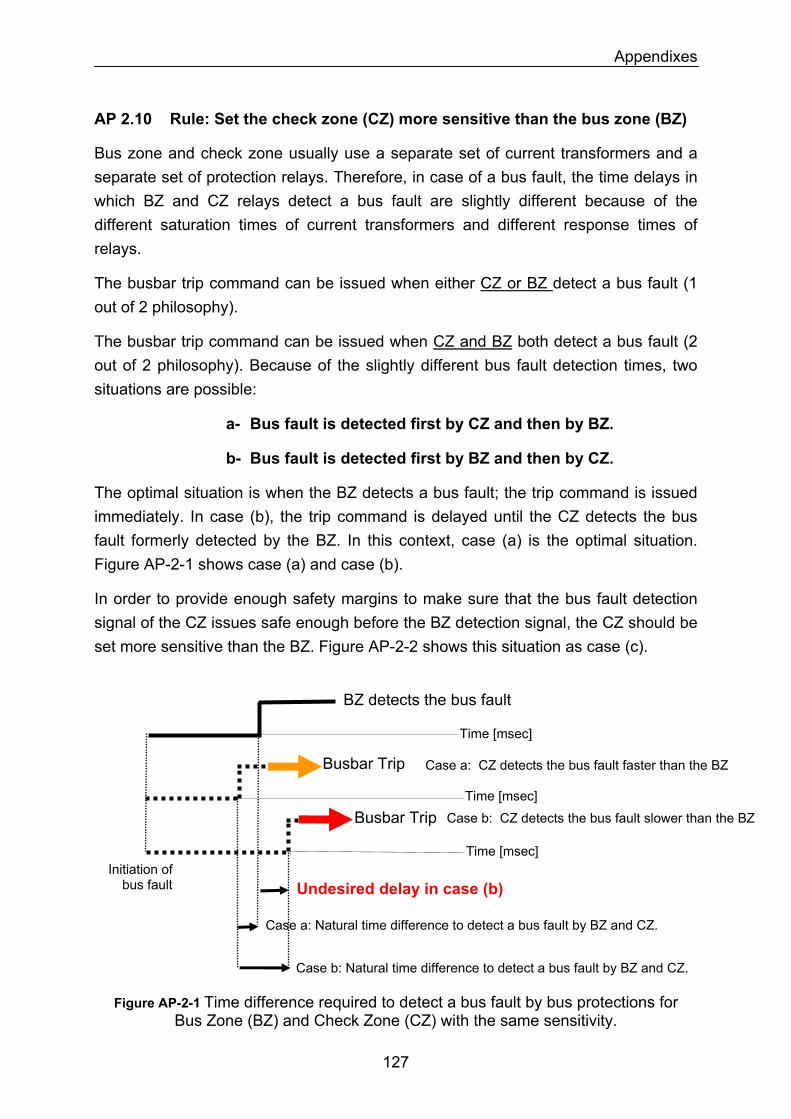
Appendixes
AP 2.10 Rule: Set the check zone (CZ) more sensitive than the bus zone (BZ)
Bus zone and check zone usually use a separate set of current transformers and a separate set of protection relays. Therefore, in case of a bus fault, the time delays in which BZ and CZ relays detect a bus fault are slightly different because of the different saturation times of current transformers and different response times of relays.
The busbar trip command can be issued when either CZ or BZ detect a bus fault (1 out of 2 philosophy).
The busbar trip command can be issued when CZ and BZ both detect a bus fault (2 out of 2 philosophy). Because of the slightly different bus fault detection times, two situations are possible:
a- Bus fault is detected first by CZ and then by BZ.
b- Bus fault is detected first by BZ and then by CZ.
The optimal situation is when the BZ detects a bus fault; the trip command is issued immediately. In case (b), the trip command is delayed until the CZ detects the bus fault formerly detected by the BZ. In this context, case (a) is the optimal situation. Figure AP-2-1 shows case (a) and case (b).
In order to provide enough safety margins to make sure that the bus fault detection signal of the CZ issues safe enough before the BZ detection signal, the CZ should be set more sensitive than the BZ. Figure AP-2-2 shows this situation as case (c).
BZ detects the bus fault
Case a: CZ detects the bus fault faster than the BZ
Initiation of bus fault
Busbar Trip
Undesired delay in case (b)
Case a: Natural time difference to detect a bus fault by BZ and CZ.
Busbar Trip
Time [msec]
Time [msec]
Time [msec]
Case b: CZ detects the bus fault slower than the BZ
Case b: Natural time difference to detect a bus fault by BZ and CZ.
Figure AP-2-1 Time difference required to detect a bus fault by bus protections for Bus Zone (BZ) and Check Zone (CZ) with the same sensitivity.
127
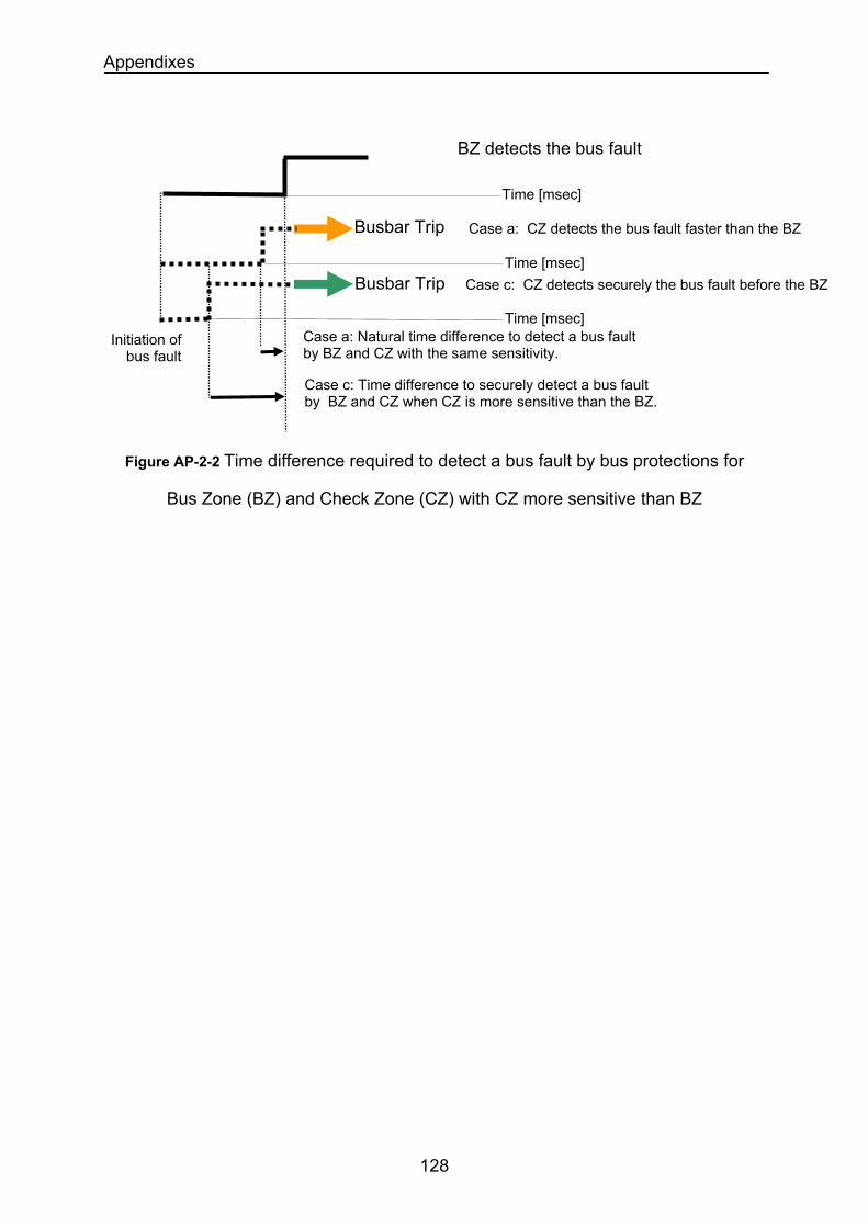
Appendixes
Figure AP-2-2 Time difference required to detect a bus fault by bus protections for
Bus Zone (BZ) and Check Zone (CZ) with CZ more sensitive than BZ
BZ detects the bus fault
Case c: CZ detects securely the bus fault before the BZ
Case a: Natural time difference to detect a bus fault by BZ and CZ with the same sensitivity.
Case c: Time difference to securely detect a bus fault by BZ and CZ when CZ is more sensitive than the BZ.
Case a: CZ detects the bus fault faster than the BZ Busbar Trip
Busbar Trip
Time [msec]
Time [msec]
Time [msec] Initiation of
bus fault
128
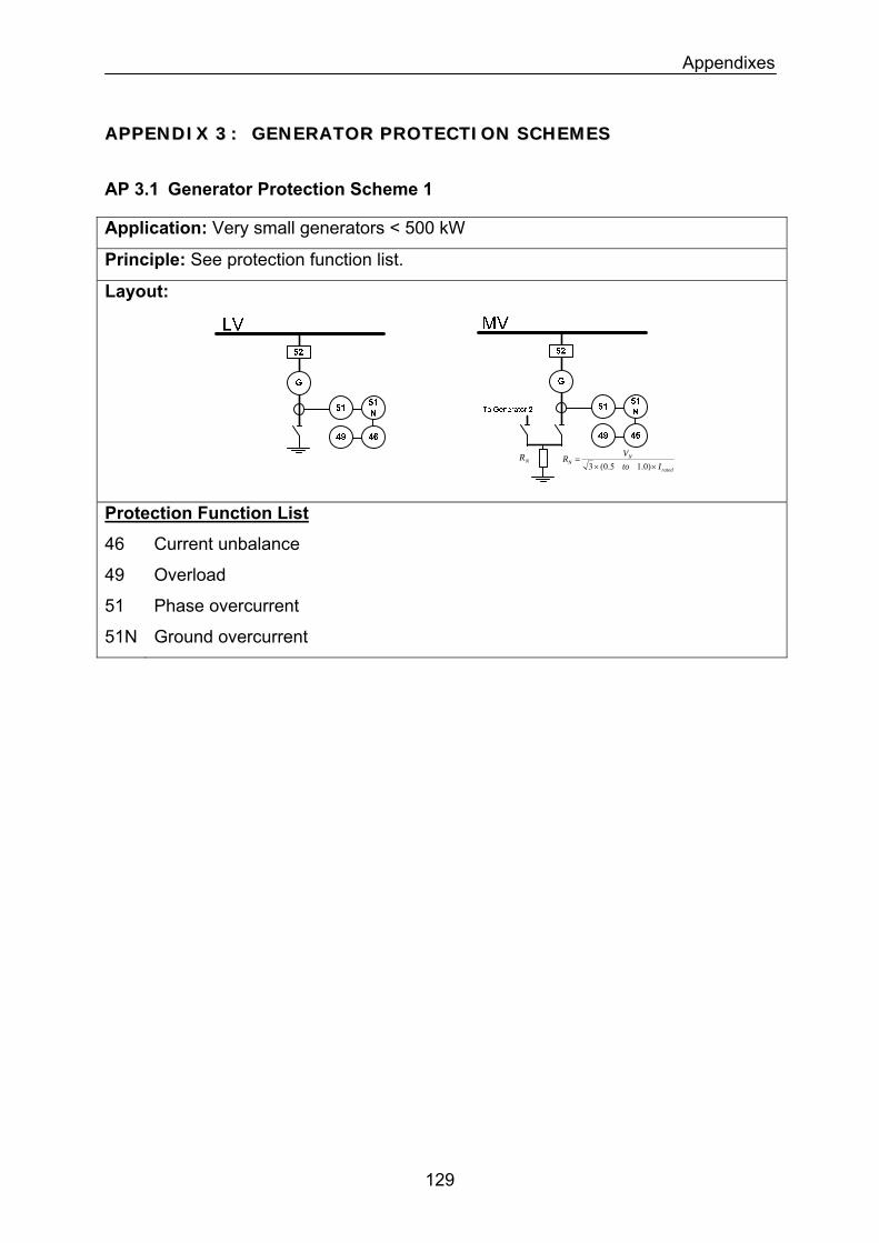
Appendixes
AAPPPPEENNDDIIXX 33 :: GGEENNEERRAATTOORR PPRROOTTEECCTTIIOONN SSCCHHEEMMEESS
AP 3.1 Generator Protection Scheme 1
Application: Very small generators < 500 kW
Principle: See protection function list.
Layout:
NR
rated
NN Ito
VR××
=)0.15.0(3
Protection Function List
46 Current unbalance
49 Overload
51 Phase overcurrent
51N Ground overcurrent
129
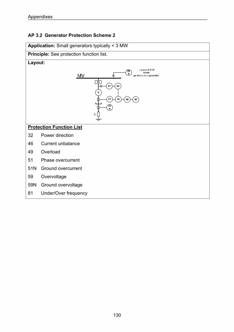
Appendixes
AP 3.2 Generator Protection Scheme 2
Application: Small generators typically < 3 MW
Principle: See protection function list.
Layout:
NR
Protection Function List
32 Power direction
46 Current unbalance
49 Overload
51 Phase overcurrent
51N Ground overcurrent
59 Overvoltage
59N Ground overvoltage
81 Under/Over frequency
130
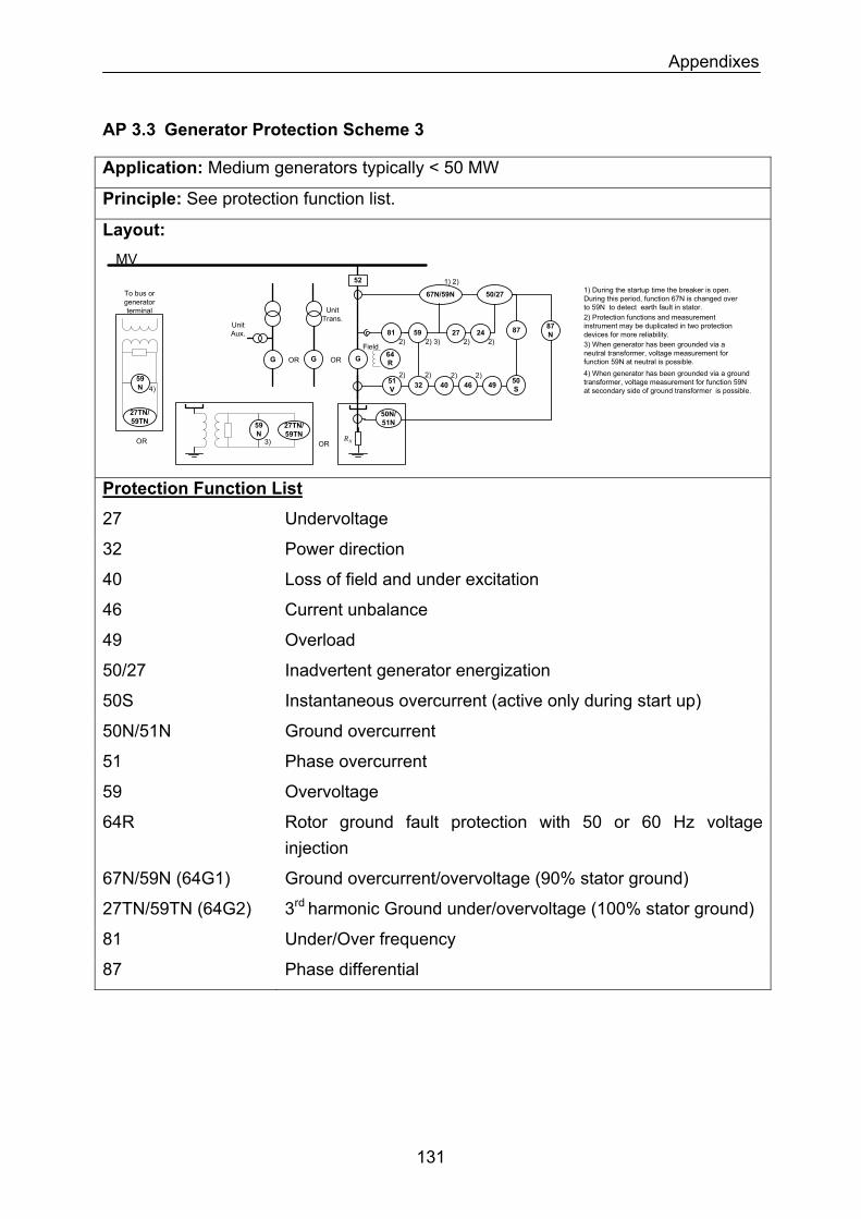
Appendixes
AP 3.3 Generator Protection Scheme 3
Application: Medium generators typically < 50 MW
Principle: See protection function list.
Layout:
51V 32
MV
G
40 46
81 59
52
Field64R
87 87N
49
50/27
27
67N/59N 1) During the startup time the breaker is open. During this period, function 67N is changed over to 59N to detect earth fault in stator.
1) 2)
2) Protection functions and measurement instrument may be duplicated in two protection devices for more reliability.
2) 2) 2) 2)
2) 3)2) 2)
OR
3) When generator has been grounded via a neutral transformer, voltage measurement for function 59N at neutral is possible.
OR
4) When generator has been grounded via a ground transformer, voltage measurement for function 59N at secondary side of ground transformer is possible.
50S
NR
3)
59N
27TN/59TN
4)
27TN/59TN
59N
GG OROR
NR
50N/51N
Unit Trans.
Unit Aux.
To bus or generator terminal
242)
Protection Function List
27 Undervoltage
32 Power direction
40 Loss of field and under excitation
46 Current unbalance
49 Overload
50/27 Inadvertent generator energization
50S Instantaneous overcurrent (active only during start up)
50N/51N Ground overcurrent
51 Phase overcurrent
59 Overvoltage
64R Rotor ground fault protection with 50 or 60 Hz voltage injection
67N/59N (64G1) Ground overcurrent/overvoltage (90% stator ground)
3rd harmonic Ground under/overvoltage (100% stator ground) 27TN/59TN (64G2)
81 Under/Over frequency
87 Phase differential
131
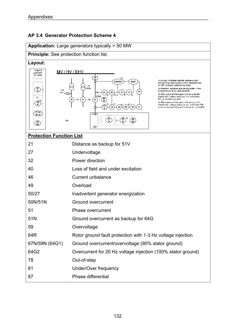
Appendixes
AP 3.4 Generator Protection Scheme 4
Application: Large generators typically > 50 MW
Principle: See protection function list.
Layout:
NRNR
NR
Protection Function List
21 Distance as backup for 51V
27 Undervoltage
32 Power direction
40 Loss of field and under excitation
46 Current unbalance
49 Overload
50/27 Inadvertent generator energization
50N/51N Ground overcurrent
51 Phase overcurrent
51N Ground overcurrent as backup for 64G
59 Overvoltage
64R Rotor ground fault protection with 1-3 Hz voltage injection
67N/59N (64G1) Ground overcurrent/overvoltage (90% stator ground)
64G2 Overcurrent for 20 Hz voltage injection (100% stator ground)
78 Out-of-step
81 Under/Over frequency
87 Phase differential
132
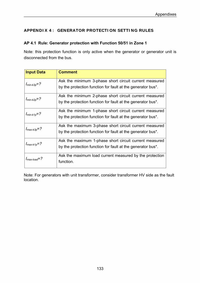
Appendixes
AAPPPPEENNDDIIXX 44 :: GGEENNEERRAATTOORR PPRROOTTEECCTTIIOONN SSEETTTTIINNGG RRUULLEESS
AP 4.1 Rule: Generator protection with Function 50/51 in Zone 1
Note: this protection function is only active when the generator or generator unit is disconnected from the bus.
Input Data Comment
Imin-k3p=? Ask the minimum 3-phase short circuit current measured by the protection function for fault at the generator bus*.
Ask the minimum 2-phase short circuit current measured by the protection function for fault at the generator bus*.
Imin-k2p=?
Ask the minimum 1-phase short circuit current measured by the protection function for fault at the generator bus*.
Imin-k1p=?
Ask the maximum 3-phase short circuit current measured by the protection function for fault at the generator bus*.
Imax-k3p=?
Ask the maximum 1-phase short circuit current measured by the protection function for fault at the generator bus*.
Imax-k1p=?
Imax-load=? Ask the maximum load current measured by the protection function.
Note: For generators with unit transformer, consider transformer HV side as the fault location.
133
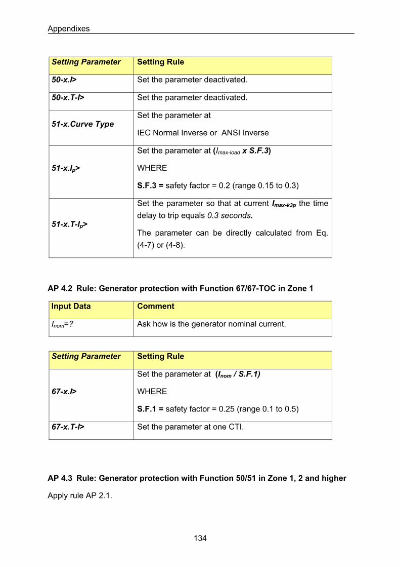
Appendixes
Setting Parameter Setting Rule
50-x.I> Set the parameter deactivated.
Set the parameter deactivated. 50-x.T-I>
51-x.Curve Type Set the parameter at
IEC Normal Inverse or ANSI Inverse
Set the parameter at (Imax-load x S.F.3)
WHERE 51-x.Ip>
S.F.3 = safety factor = 0.2 (range 0.15 to 0.3)
51-x.T-Ip>
Set the parameter so that at current Imax-k3p the time delay to trip equals 0.3 seconds.
The parameter can be directly calculated from Eq. (4-7) or (4-8).
AP 4.2 Rule: Generator protection with Function 67/67-TOC in Zone 1
Input Data Comment
Ask how is the generator nominal current. Inom=?
Setting Parameter Setting Rule
67-x.I>
Set the parameter at (Inom / S.F.1)
WHERE
S.F.1 = safety factor = 0.25 (range 0.1 to 0.5)
67-x.T-I> Set the parameter at one CTI.
AP 4.3 Rule: Generator protection with Function 50/51 in Zone 1, 2 and higher
Apply rule AP 2.1.
134
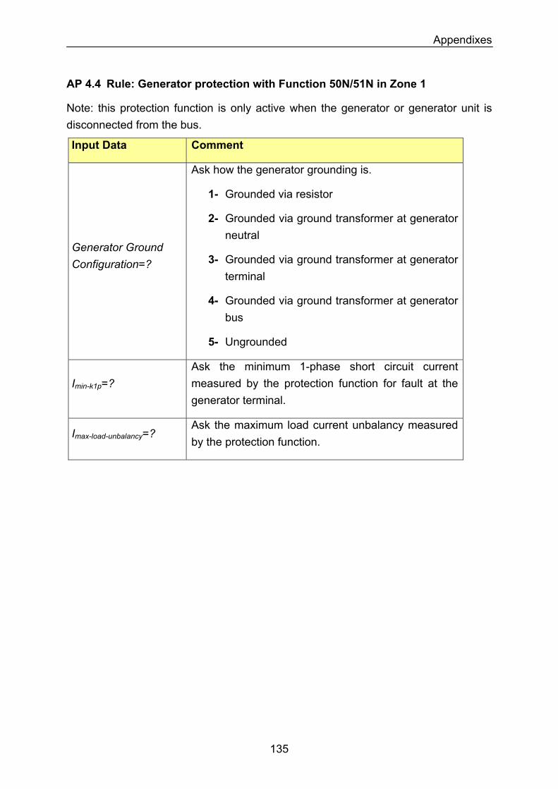
Appendixes
AP 4.4 Rule: Generator protection with Function 50N/51N in Zone 1
Note: this protection function is only active when the generator or generator unit is disconnected from the bus.
Input Data Comment
Ask how the generator grounding is.
1- Grounded via resistor
2- Grounded via ground transformer at generator neutral
Generator Ground Configuration=? 3- Grounded via ground transformer at generator
terminal
4- Grounded via ground transformer at generator bus
5- Ungrounded
Imin-k1p=? Ask the minimum 1-phase short circuit current measured by the protection function for fault at the generator terminal.
Imax-load-unbalancy=? Ask the maximum load current unbalancy measured by the protection function.
135
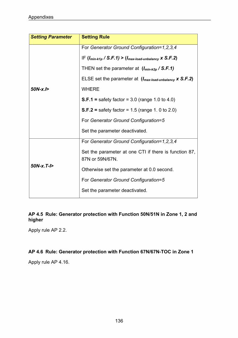
Appendixes
Setting Parameter Setting Rule
50N-x.I>
For Generator Ground Configuration=1,2,3,4
IF (Imin-k1p / S.F.1) > (Imax-load-unbalancy x S.F.2)
THEN set the parameter at (Imin-k2p / S.F.1)
ELSE set the parameter at (Imax-load-unbalancy x S.F.2)
WHERE
S.F.1 = safety factor = 3.0 (range 1.0 to 4.0)
S.F.2 = safety factor = 1.5 (range 1. 0 to 2.0)
For Generator Ground Configuration=5
Set the parameter deactivated.
For Generator Ground Configuration=1,2,3,4
Set the parameter at one CTI if there is function 87, 87N or 59N/67N.
Otherwise set the parameter at 0.0 second. 50N-x.T-I>
For Generator Ground Configuration=5
Set the parameter deactivated.
AP 4.5 Rule: Generator protection with Function 50N/51N in Zone 1, 2 and higher
Apply rule AP 2.2.
AP 4.6 Rule: Generator protection with Function 67N/67N-TOC in Zone 1
Apply rule AP 4.16.
136
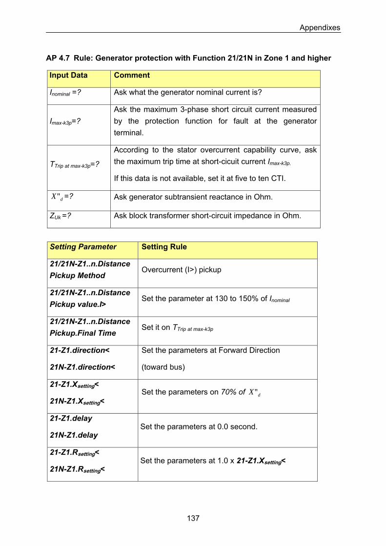
Appendixes
AP 4.7 Rule: Generator protection with Function 21/21N in Zone 1 and higher
Input Data Comment
Ask what the generator nominal current is? Inominal =?
Ask the maximum 3-phase short circuit current measured by the protection function for fault at the generator terminal.
Imax-k3p=?
According to the stator overcurrent capability curve, ask the maximum trip time at short-cicuit current Imax-k3p. TTrip at max-k3p=?
If this data is not available, set it at five to ten CTI.
dX" =? Ask generator subtransient reactance in Ohm.
ZUk =? Ask block transformer short-circuit impedance in Ohm.
Setting Parameter Setting Rule
21/21N-Z1..n.Distance Pickup Method
Overcurrent (I>) pickup
21/21N-Z1..n.Distance Pickup value.I>
Set the parameter at 130 to 150% of Inominal
21/21N-Z1..n.Distance Pickup.Final Time
Set it on TTrip at max-k3p
21-Z1.direction< Set the parameters at Forward Direction
(toward bus) 21N-Z1.direction<
21-Z1.Xsetting<
21N-Z1.Xsetting< Set the parameters on 70% of dX"
21-Z1.delay
21N-Z1.delay Set the parameters at 0.0 second.
21-Z1.Rsetting<
21N-Z1.Rsetting< Set the parameters at 1.0 x 21-Z1.Xsetting<
137
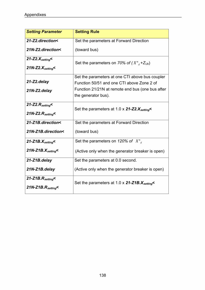
Appendixes
Setting Parameter Setting Rule
21-Z2.direction<
21N-Z2.direction<
Set the parameters at Forward Direction
(toward bus)
21-Z2.Xsetting<
21N-Z2.Xsetting< Set the parameters on 70% of ( +ZdX" Uk)
21-Z2.delay
21N-Z2.delay
Set the parameters at one CTI above bus coupler Function 50/51 and one CTI above Zone 2 of Function 21/21N at remote end bus (one bus after the generator bus).
21-Z2.Rsetting<
21N-Z2.Rsetting< Set the parameters at 1.0 x 21-Z2.Xsetting<
21-Z1B.direction<
21N-Z1B.direction<
Set the parameters at Forward Direction
(toward bus)
Set the parameters on 120% of dX"21-Z1B.Xsetting<
21N-Z1B.Xsetting< (Active only when the generator breaker is open)
21-Z1B.delay
21N-Z1B.delay
Set the parameters at 0.0 second.
(Active only when the generator breaker is open)
21-Z1B.Rsetting<
21N-Z1B.Rsetting< Set the parameters at 1.0 x 21-Z1B.Xsetting<
138
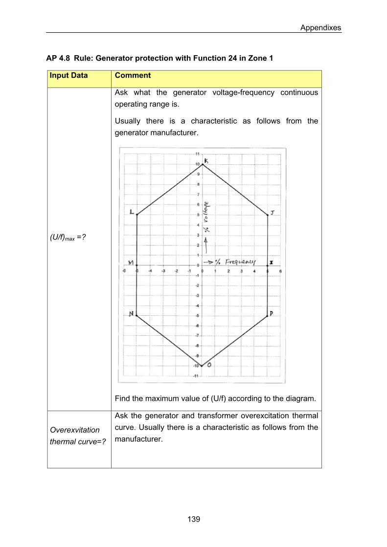
Appendixes
AP 4.8 Rule: Generator protection with Function 24 in Zone 1
Input Data Comment
(U/f)max =?
Ask what the generator voltage-frequency continuous operating range is.
Usually there is a characteristic as follows from the generator manufacturer.
Find the maximum value of (U/f) according to the diagram.
Overexvitation thermal curve=?
Ask the generator and transformer overexcitation thermal curve. Usually there is a characteristic as follows from the manufacturer.
139
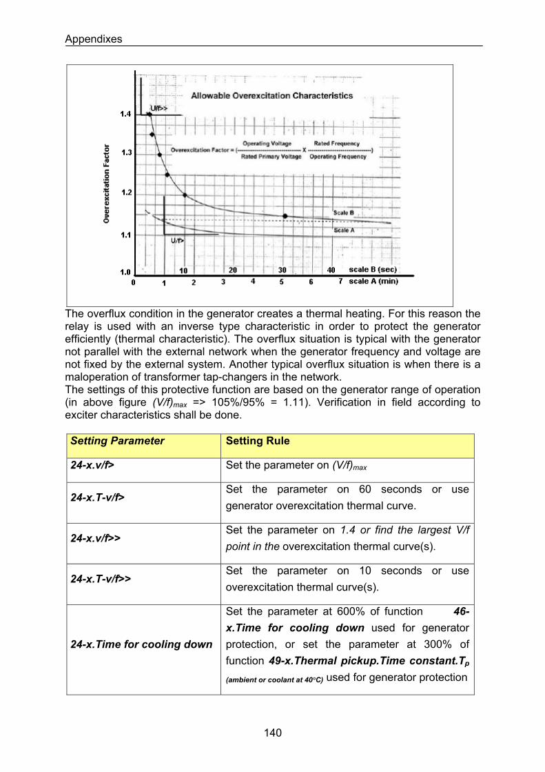
Appendixes
The overflux condition in the generator creates a thermal heating. For this reason the relay is used with an inverse type characteristic in order to protect the generator efficiently (thermal characteristic). The overflux situation is typical with the generator not parallel with the external network when the generator frequency and voltage are not fixed by the external system. Another typical overflux situation is when there is a maloperation of transformer tap-changers in the network. The settings of this protective function are based on the generator range of operation (in above figure (V/f)max => 105%/95% = 1.11). Verification in field according to exciter characteristics shall be done. Setting Parameter Setting Rule
Set the parameter on (V/f)max24-x.v/f>
Set the parameter on 60 seconds or use generator overexcitation thermal curve.
24-x.T-v/f>
Set the parameter on 1.4 or find the largest V/f point in the overexcitation thermal curve(s).
24-x.v/f>>
Set the parameter on 10 seconds or use overexcitation thermal curve(s).
24-x.T-v/f>>
24-x.Time for cooling down
Set the parameter at 600% of function 46-x.Time for cooling down used for generator protection, or set the parameter at 300% of function 49-x.Thermal pickup.Time constant.Tp
(ambient or coolant at 40°C) used for generator protection
140
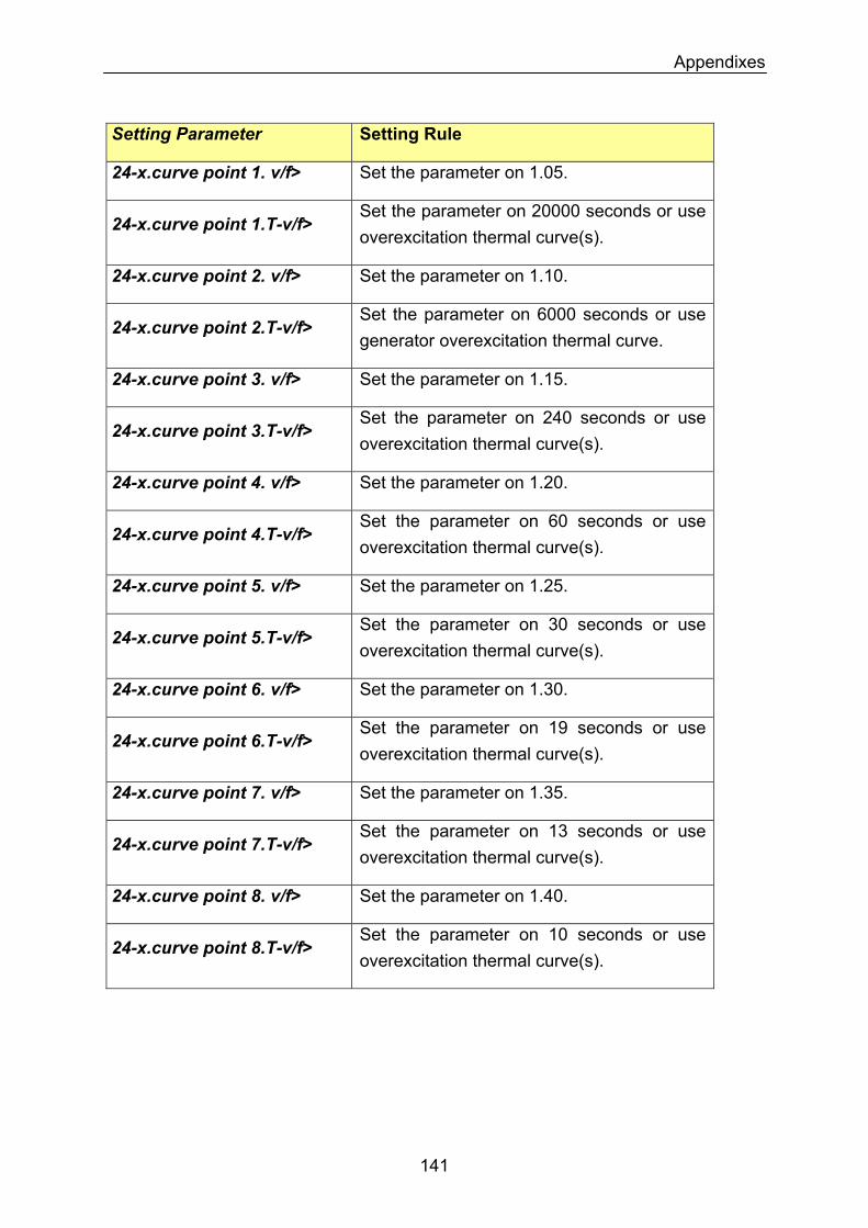
Appendixes
Setting Parameter Setting Rule
24-x.curve point 1. v/f> Set the parameter on 1.05.
24-x.curve point 1.T-v/f> Set the parameter on 20000 seconds or use overexcitation thermal curve(s).
24-x.curve point 2. v/f> Set the parameter on 1.10.
24-x.curve point 2.T-v/f> Set the parameter on 6000 seconds or use generator overexcitation thermal curve.
24-x.curve point 3. v/f> Set the parameter on 1.15.
24-x.curve point 3.T-v/f> Set the parameter on 240 seconds or use overexcitation thermal curve(s).
24-x.curve point 4. v/f> Set the parameter on 1.20.
24-x.curve point 4.T-v/f> Set the parameter on 60 seconds or use overexcitation thermal curve(s).
24-x.curve point 5. v/f> Set the parameter on 1.25.
24-x.curve point 5.T-v/f> Set the parameter on 30 seconds or use overexcitation thermal curve(s).
24-x.curve point 6. v/f> Set the parameter on 1.30.
Set the parameter on 19 seconds or use overexcitation thermal curve(s).
24-x.curve point 6.T-v/f>
Set the parameter on 1.35. 24-x.curve point 7. v/f>
Set the parameter on 13 seconds or use overexcitation thermal curve(s).
24-x.curve point 7.T-v/f>
24-x.curve point 8. v/f> Set the parameter on 1.40.
24-x.curve point 8.T-v/f> Set the parameter on 10 seconds or use overexcitation thermal curve(s).
141
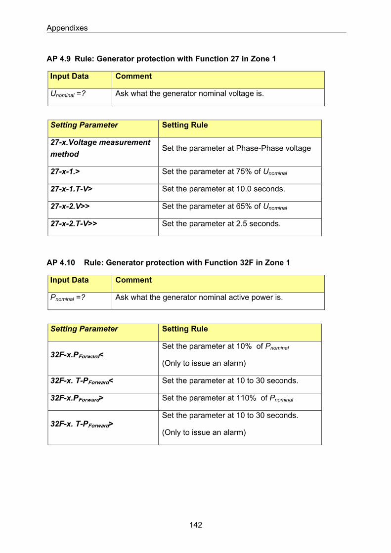
Appendixes
AP 4.9 Rule: Generator protection with Function 27 in Zone 1
Input Data Comment
Ask what the generator nominal voltage is. Unominal =?
Setting Parameter Setting Rule
27-x.Voltage measurement method
Set the parameter at Phase-Phase voltage
Set the parameter at 75% of Unominal27-x-1.>
Set the parameter at 10.0 seconds. 27-x-1.T-V>
27-x-2.V>> Set the parameter at 65% of Unominal
27-x-2.T-V>> Set the parameter at 2.5 seconds.
AP 4.10 Rule: Generator protection with Function 32F in Zone 1
Input Data Comment
Ask what the generator nominal active power is. Pnominal =?
Setting Parameter Setting Rule
32F-x.PForward< Set the parameter at 10% of Pnominal
(Only to issue an alarm)
32F-x. T-PForward< Set the parameter at 10 to 30 seconds.
32F-x.PForward> Set the parameter at 110% of Pnominal
32F-x. T-PForward> Set the parameter at 10 to 30 seconds.
(Only to issue an alarm)
142
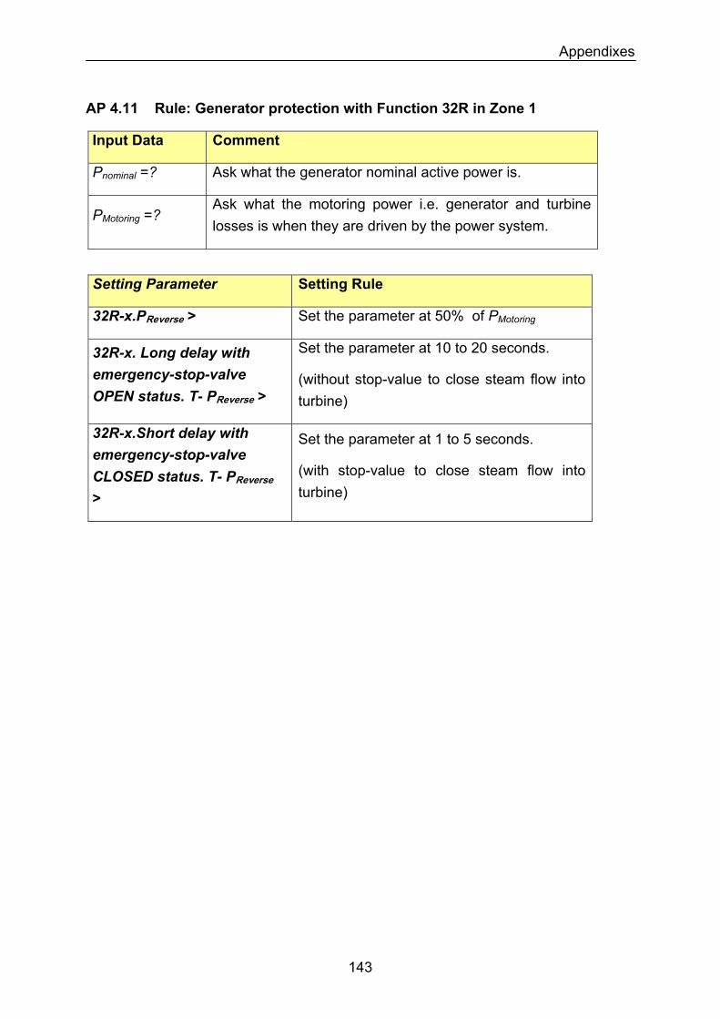
Appendixes
AP 4.11 Rule: Generator protection with Function 32R in Zone 1
Input Data Comment
Pnominal =? Ask what the generator nominal active power is.
PMotoring =? Ask what the motoring power i.e. generator and turbine losses is when they are driven by the power system.
Setting Parameter Setting Rule
Set the parameter at 50% of PMotoring32R-x.PReverse >
32R-x. Long delay with emergency-stop-valve OPEN status. T- PReverse >
Set the parameter at 10 to 20 seconds.
(without stop-value to close steam flow into turbine)
32R-x.Short delay with emergency-stop-valve CLOSED status. T- PReverse >
Set the parameter at 1 to 5 seconds.
(with stop-value to close steam flow into turbine)
143
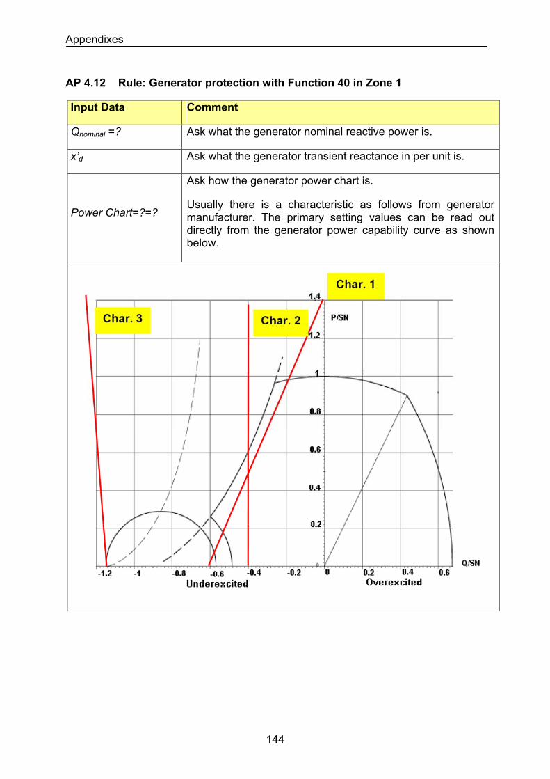
Appendixes
AP 4.12 Rule: Generator protection with Function 40 in Zone 1
Input Data Comment
Qnominal =? Ask what the generator nominal reactive power is.
x’d Ask what the generator transient reactance in per unit is.
Ask how the generator power chart is.
Usually there is a characteristic as follows from generator manufacturer. The primary setting values can be read out directly from the generator power capability curve as shown below.
Power Chart=?=?
144
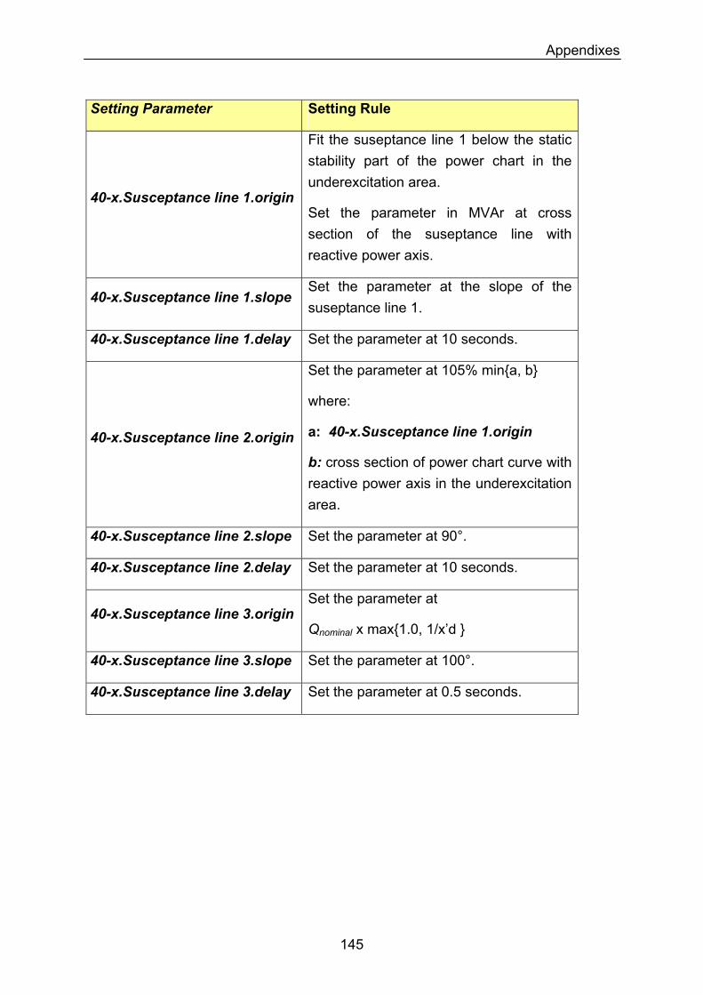
Appendixes
Setting Parameter Setting Rule
40-x.Susceptance line 1.origin
Fit the suseptance line 1 below the static stability part of the power chart in the underexcitation area.
Set the parameter in MVAr at cross section of the suseptance line with reactive power axis.
40-x.Susceptance line 1.slope Set the parameter at the slope of the suseptance line 1.
40-x.Susceptance line 1.delay Set the parameter at 10 seconds.
Set the parameter at 105% mina, b
where:
a: 40-x.Susceptance line 1.origin 40-x.Susceptance line 2.origin
b: cross section of power chart curve with reactive power axis in the underexcitation area.
Set the parameter at 90°. 40-x.Susceptance line 2.slope
Set the parameter at 10 seconds. 40-x.Susceptance line 2.delay
Set the parameter at 40-x.Susceptance line 3.origin
Qnominal x max1.0, 1/x’d
40-x.Susceptance line 3.slope Set the parameter at 100°.
40-x.Susceptance line 3.delay Set the parameter at 0.5 seconds.
145
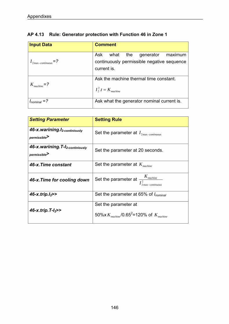
Appendixes
AP 4.13 Rule: Generator protection with Function 46 in Zone 1
Input Data Comment
Ask what the generator maximum continuously permissible negative sequence current is.
continuousI −max2 =?
Ask the machine thermal time constant. machineK =?
machineKtI =.22
Ask what the generator nominal current is. Inominal =?
Setting Parameter Setting Rule
46-x.warining.I2-continiously
permissible> Set the parameter at continuousI −max2
46-x.warining.T-I2-continiously
permissible> Set the parameter at 20 seconds.
Set the parameter at machineK46-x.Time constant
Set the parameter at 2max2 continuous
machine
IK
−
46-x.Time for cooling down
Set the parameter at 65% of Inominal46-x.trip.I2>>
46-x.trip.T-I2>> Set the parameter at
50%x /0.65machineK 2=120% of machineK
146
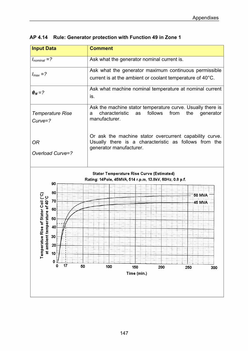
Appendixes
AP 4.14 Rule: Generator protection with Function 49 in Zone 1
Input Data Comment
Inominal =? Ask what the generator nominal current is.
Imax =? Ask what the generator maximum continuous permissible current is at the ambient or coolant temperature of 40°C.
θN =? Ask what machine nominal temperature at nominal current is.
Temperature Rise Curve=?
Ask the machine stator temperature curve. Usually there is a characteristic as follows from the generator manufacturer. Or ask the machine stator overcurrent capability curve. Usually there is a characteristic as follows from the generator manufacturer.
OR
Overload Curve=?
147
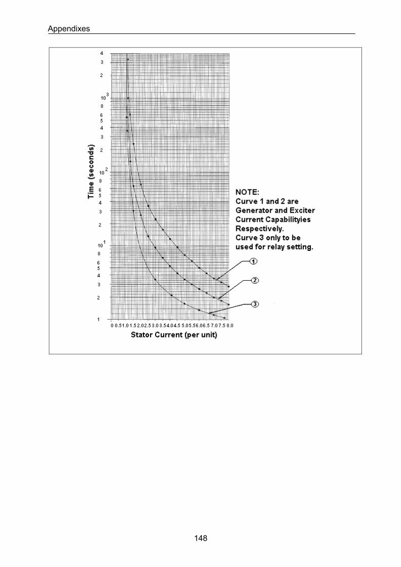
Appendixes
148
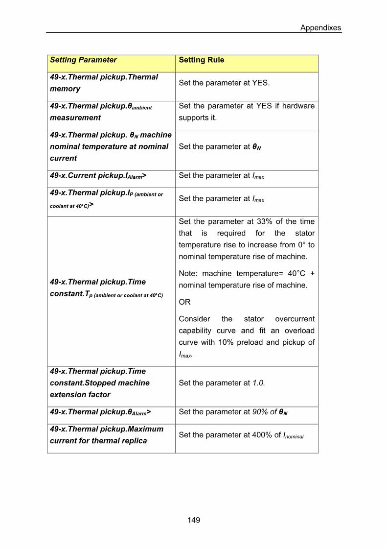
Appendixes
Setting Parameter Setting Rule
49-x.Thermal pickup.Thermal memory
Set the parameter at YES.
49-x.Thermal pickup.θambient measurement
Set the parameter at YES if hardware supports it.
49-x.Thermal pickup. θN machine nominal temperature at nominal current
Set the parameter at θN
49-x.Current pickup.IAlarm> Set the parameter at Imax
49-x.Thermal pickup.IP (ambient or
coolant at 40°C)> Set the parameter at Imax
Set the parameter at 33% of the time that is required for the stator temperature rise to increase from 0° to nominal temperature rise of machine.
Note: machine temperature= 40°C + nominal temperature rise of machine.
OR
49-x.Thermal pickup.Time constant.Tp (ambient or coolant at 40°C)
Consider the stator overcurrent capability curve and fit an overload curve with 10% preload and pickup of Imax.
49-x.Thermal pickup.Time constant.Stopped machine extension factor
Set the parameter at 1.0.
49-x.Thermal pickup.θAlarm> Set the parameter at 90% of θN
49-x.Thermal pickup.Maximum current for thermal replica
Set the parameter at 400% of Inominal
149
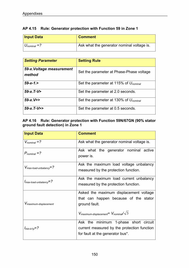
Appendixes
AP 4.15 Rule: Generator protection with Function 59 in Zone 1
Input Data Comment
Ask what the generator nominal voltage is. Unominal =?
Setting Parameter Setting Rule
59-x.Voltage measurement method
Set the parameter at Phase-Phase voltage
Set the parameter at 115% of Unominal59-x-1.>
Set the parameter at 2.0 seconds. 59-x.T-V>
Set the parameter at 130% of Unominal59-x.V>>
Set the parameter at 0.5 seconds. 59-x.T-V>>
AP 4.16 Rule: Generator protection with Function 59N/67GN (90% stator ground fault detection) in Zone 1
Input Data Comment
Ask what the generator nominal voltage is. Vnominal =?
Ask what the generator nominal active power is.
Pnominal =?
Vmax-load-unbalancy=? Ask the maximum load voltage unbalancy measured by the protection function.
Imax-load-unbalancy=? Ask the maximum load current unbalancy measured by the protection function.
Vmaximum-displacement
Asked the maximum displacement voltage that can happen because of the stator ground fault.
Vmaximum-displacement= Vnominal/ 3
Ask the minimum 1-phase short circuit current measured by the protection function for fault at the generator bus*.
Imin-k1p=?
150
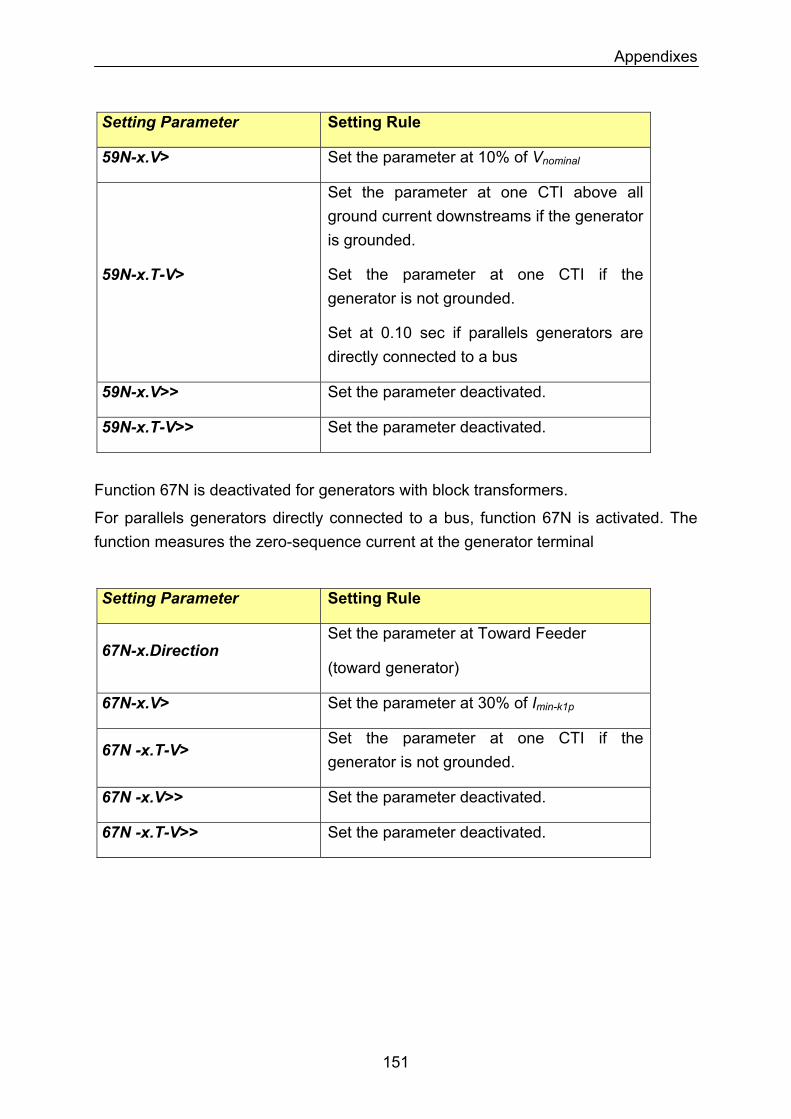
Appendixes
Setting Parameter Setting Rule
Set the parameter at 10% of Vnominal59N-x.V>
59N-x.T-V>
Set the parameter at one CTI above all ground current downstreams if the generator is grounded.
Set the parameter at one CTI if the generator is not grounded.
Set at 0.10 sec if parallels generators are directly connected to a bus
59N-x.V>> Set the parameter deactivated.
Set the parameter deactivated. 59N-x.T-V>>
Function 67N is deactivated for generators with block transformers.
For parallels generators directly connected to a bus, function 67N is activated. The function measures the zero-sequence current at the generator terminal
Setting Parameter Setting Rule
Set the parameter at Toward Feeder 67N-x.Direction
(toward generator)
Set the parameter at 30% of Imin-k1p67N-x.V>
67N -x.T-V> Set the parameter at one CTI if the generator is not grounded.
67N -x.V>> Set the parameter deactivated.
67N -x.T-V>> Set the parameter deactivated.
151
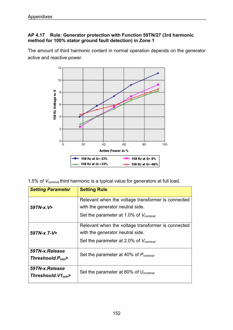
Appendixes
AP 4.17 Rule: Generator protection with Function 59TN/27 (3rd harmonic method for 100% stator ground fault detection) in Zone 1
The amount of third harmonic content in normal operation depends on the generator active and reactive power.
1.5% of Vnominal third harmonic is a typical value for generators at full load.
Setting Parameter Setting Rule
59TN-x.V> Relevant when the voltage transformer is connected with the generator neutral side.
Set the parameter at 1.0% of Vnominal
59TN-x.T-V> Relevant when the voltage transformer is connected with the generator neutral side.
Set the parameter at 2.0% of Vnominal
59TN-x.Release Threshould.Pmin>
Set the parameter at 40% of Pnominal
59TN-x.Release Threshould.V1min>
Set the parameter at 80% of Unominal
152
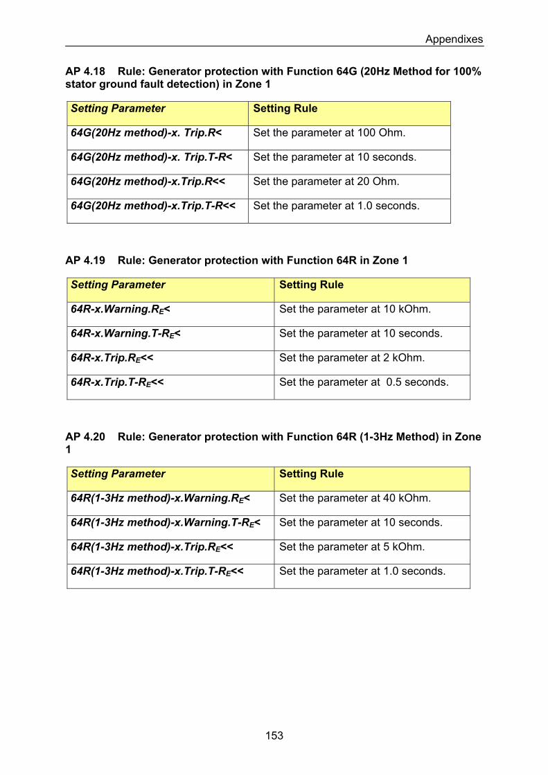
Appendixes
AP 4.18 Rule: Generator protection with Function 64G (20Hz Method for 100% stator ground fault detection) in Zone 1
Setting Parameter Setting Rule
Set the parameter at 100 Ohm. 64G(20Hz method)-x. Trip.R<
Set the parameter at 10 seconds. 64G(20Hz method)-x. Trip.T-R<
Set the parameter at 20 Ohm. 64G(20Hz method)-x.Trip.R<<
Set the parameter at 1.0 seconds. 64G(20Hz method)-x.Trip.T-R<<
AP 4.19 Rule: Generator protection with Function 64R in Zone 1
Setting Parameter Setting Rule
Set the parameter at 10 kOhm. 64R-x.Warning.RE<
Set the parameter at 10 seconds. 64R-x.Warning.T-RE<
Set the parameter at 2 kOhm. 64R-x.Trip.RE<<
Set the parameter at 0.5 seconds. 64R-x.Trip.T-RE<<
AP 4.20 Rule: Generator protection with Function 64R (1-3Hz Method) in Zone 1
Setting Parameter Setting Rule
Set the parameter at 40 kOhm. 64R(1-3Hz method)-x.Warning.RE<
Set the parameter at 10 seconds. 64R(1-3Hz method)-x.Warning.T-RE<
Set the parameter at 5 kOhm. 64R(1-3Hz method)-x.Trip.RE<<
Set the parameter at 1.0 seconds. 64R(1-3Hz method)-x.Trip.T-RE<<
153
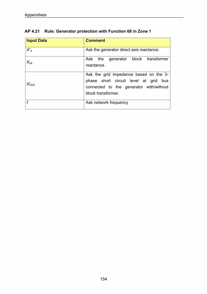
Appendixes
AP 4.21 Rule: Generator protection with Function 68 in Zone 1
Input Data Comment
Ask the generator direct axis reactance. X’d
Ask the generator block transformer reactance.
Xuk
XGrid
Ask the grid impedance based on the 3-phase short circuit level at grid bus connected to the generator with/without block transformer.
Ask network frequency f
154
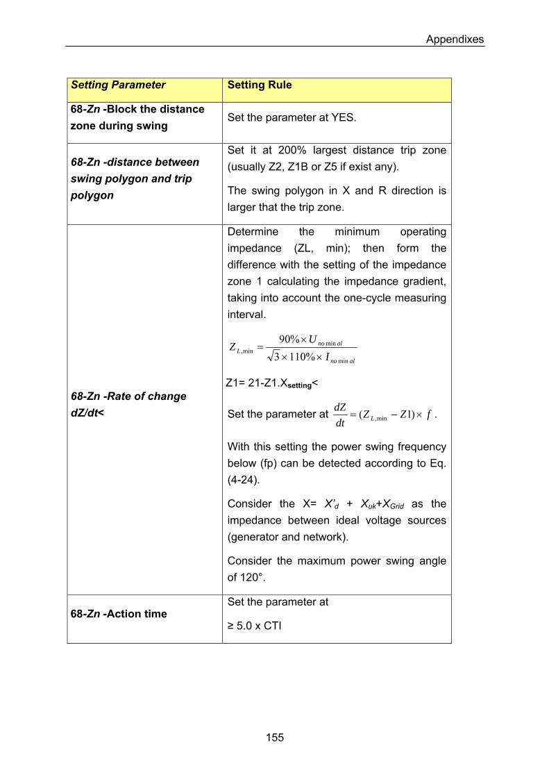
Appendixes
Setting Parameter Setting Rule
68-Zn -Block the distance zone during swing
Set the parameter at YES.
68-Zn -distance between swing polygon and trip polygon
Set it at 200% largest distance trip zone (usually Z2, Z1B or Z5 if exist any).
The swing polygon in X and R direction is larger that the trip zone.
68-Zn -Rate of change dZ/dt<
Determine the minimum operating impedance (ZL, min); then form the difference with the setting of the impedance zone 1 calculating the impedance gradient, taking into account the one-cycle measuring interval.
alno
alnoL I
UZ
min
minmin, %1103
%90××
×=
Z1= 21-Z1.Xsetting<
Set the parameter at fZZdtdZ
L ×−= )1( min, .
With this setting the power swing frequency below (fp) can be detected according to Eq. (4-24).
Consider the X= X’d + Xuk+XGrid as the impedance between ideal voltage sources (generator and network).
Consider the maximum power swing angle of 120°.
68-Zn -Action time Set the parameter at
≥ 5.0 x CTI
155
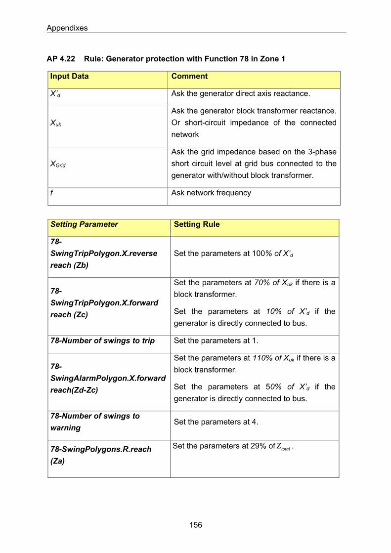
Appendixes
AP 4.22 Rule: Generator protection with Function 78 in Zone 1
Input Data Comment
Ask the generator direct axis reactance. X’d
Xuk
Ask the generator block transformer reactance. Or short-circuit impedance of the connected network
XGrid
Ask the grid impedance based on the 3-phase short circuit level at grid bus connected to the generator with/without block transformer.
Ask network frequency f
Setting Parameter Setting Rule
78-SwingTripPolygon.X.reverse reach (Zb)
Set the parameters at 100% of X’d
78-SwingTripPolygon.X.forward reach (Zc)
Set the parameters at 70% of Xuk if there is a block transformer.
Set the parameters at 10% of X’d if the generator is directly connected to bus.
Set the parameters at 1. 78-Number of swings to trip
Set the parameters at 110% of Xuk if there is a block transformer. 78-
SwingAlarmPolygon.X.forward reach(Zd-Zc) Set the parameters at 50% of X’d if the
generator is directly connected to bus.
78-Number of swings to warning
Set the parameters at 4.
Set the parameters at 29% of . totalZ78-SwingPolygons.R.reach (Za)
156
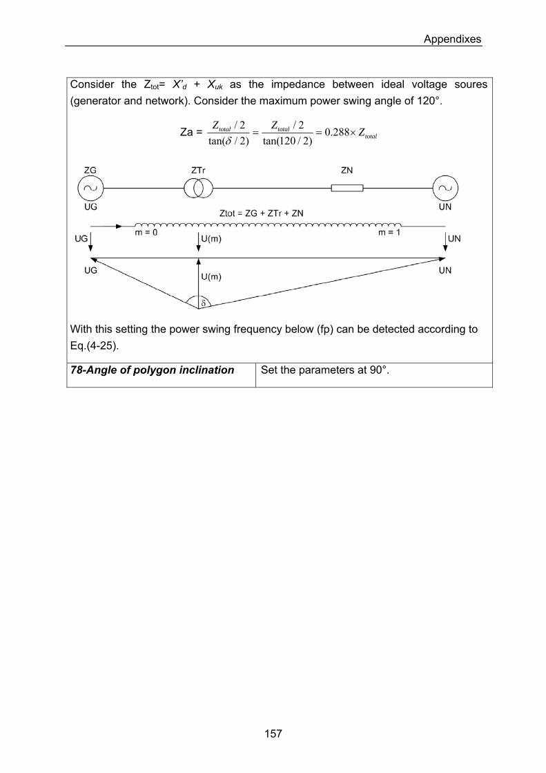
Appendixes
Consider the Ztot= X’d + Xuk as the impedance between ideal voltage soures (generator and network). Consider the maximum power swing angle of 120°.
Za = totaltotaltotal ZZZ
×== 288.0)2/120tan(
2/)2/tan(
2/δ
With this setting the power swing frequency below (fp) can be detected according to Eq.(4-25).
78-Angle of polygon inclination Set the parameters at 90°.
157
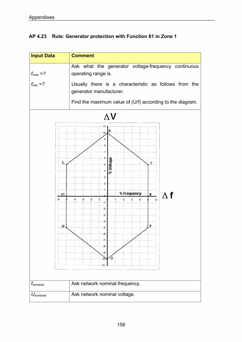
Appendixes
AP 4.23 Rule: Generator protection with Function 81 in Zone 1
Input Data Comment
Ask what the generator voltage-frequency continuous operating range is. fmax =?
fmin =?
Usually there is a characteristic as follows from the generator manufacturer.
Find the maximum value of (U/f) according to the diagram.
Ask network nominal frequency. fnominal
Ask network nominal voltage. Unominal
158
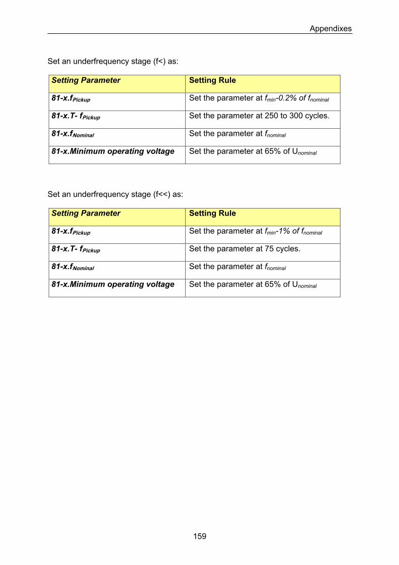
Appendixes
Set an underfrequency stage (f<) as: Setting Parameter Setting Rule
81-x.fPickup Set the parameter at fmin-0.2% of fnominal
81-x.T- fPickup Set the parameter at 250 to 300 cycles.
81-x.fNominal Set the parameter at fnominal
81-x.Minimum operating voltage Set the parameter at 65% of Unominal
Set an underfrequency stage (f<<) as: Setting Parameter Setting Rule
81-x.fPickup Set the parameter at fmin-1% of fnominal
81-x.T- fPickup Set the parameter at 75 cycles.
81-x.fNominal Set the parameter at fnominal
81-x.Minimum operating voltage Set the parameter at 65% of Unominal
159
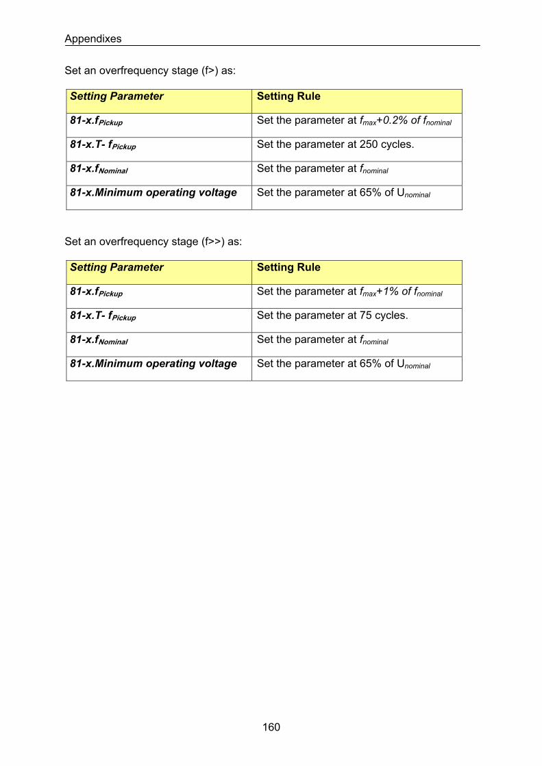
Appendixes
Set an overfrequency stage (f>) as: Setting Parameter Setting Rule
Set the parameter at fmax+0.2% of fnominal81-x.fPickup
Set the parameter at 250 cycles. 81-x.T- fPickup
Set the parameter at fnominal81-x.fNominal
Set the parameter at 65% of Unominal81-x.Minimum operating voltage
Set an overfrequency stage (f>>) as: Setting Parameter Setting Rule
Set the parameter at fmax+1% of fnominal81-x.fPickup
Set the parameter at 75 cycles. 81-x.T- fPickup
Set the parameter at fnominal81-x.fNominal
81-x.Minimum operating voltage Set the parameter at 65% of Unominal
160
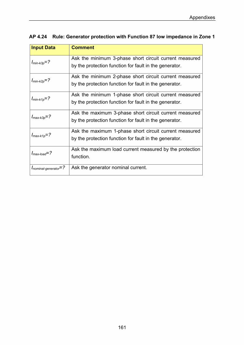
Appendixes
AP 4.24 Rule: Generator protection with Function 87 low impedance in Zone 1
Input Data Comment
Imin-k3p=? Ask the minimum 3-phase short circuit current measured by the protection function for fault in the generator.
Imin-k2p=? Ask the minimum 2-phase short circuit current measured by the protection function for fault in the generator.
Ask the minimum 1-phase short circuit current measured by the protection function for fault in the generator.
Imin-k1p=?
Ask the maximum 3-phase short circuit current measured by the protection function for fault in the generator.
Imax-k3p=?
Ask the maximum 1-phase short circuit current measured by the protection function for fault in the generator.
Imax-k1p=?
Imax-load=? Ask the maximum load current measured by the protection function.
Inominal-generator=? Ask the generator nominal current.
161
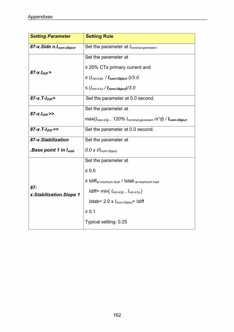
Appendixes
Setting Parameter Setting Rule
Set the parameter at Inominal-generator. 87-x.Side n.Inom-Object
87-x.IDiff >
Set the parameter at
≥ 20% CTs primary current and
≤ (Imin-k2p / Inom-Object /)/3.0
≤ (Imin-k1p / Inom-Object)/3.0
87-x.T-IDiff > Set the parameter at 0.0 second.
87-x.IDiff >> Set the parameter at
maxImax-k3p , 120% Inominal-generator./x”d / Inom-Object
87-x.T-IDiff >> Set the parameter at 0.0 second.
Set the parameter at 87-x.Stabilization
.Base point 1 in Istab 0.0 x I/Inom-Object
87-x.Stabilization.Slope 1
Set the parameter at
≤ 0.5
≥ Idiffat minimum fault / Istab at maximum load
Idiff= min Imin-k2p , Imin-k1p
Istab= 2.0 x Inom-Object+ Idiff
≥ 0.1
Typical setting: 0.25
162

Appendixes
Setting Parameter Setting Rule
87-x.Stabilization.Base point 2 in Istab
Set the parameter at
2.5 x I/Inom-Object
Ignore any trip by slope 2 as long as the sum of incoming current to bus is 125% Inom-Object. Above this setting, stabilize the differential protection against CT saturation for external faults.
Set the parameter at
≤ 0.95
≥ 0.25
≥Idiff / (Istab - Base point 2 )
S.F.= Saturation Factor to one CT=
Idiff= S.F. x Imax-k3p / Inom-Object (blocking target)
Istab= 2.0 x Imax-k3p / Inom-Object
As an example: S.F.= 95%, Base Point 2 = 2.5
CT primary current = 2000 A, Imax-k3p = 40 kA
then Slope 2 ≥ 0.5
This settings block the operation of differential protection if an external fault with magnitude of Imax-
k3p happens and CTs at one feeder are saturated so that the differential current around
95% of Imax-k3p/ Inom-Object is observed.
87-x.Stabilization.Slope 2
The setting can be more sensitive by reducing the saturation factor if an exact value from a simulation is available. By simulation, simultaneous saturation of CTs can also be evaluated.
163
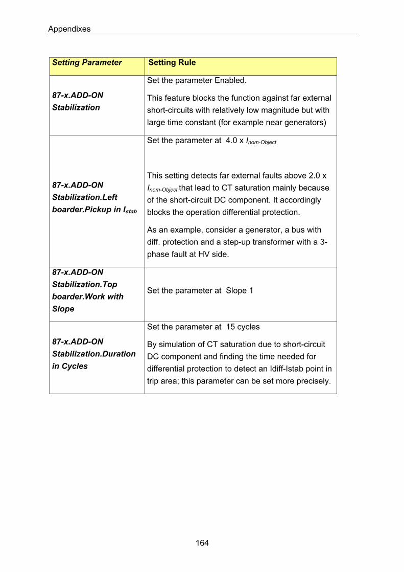
Appendixes
Setting Parameter Setting Rule
87-x.ADD-ON Stabilization
Set the parameter Enabled.
This feature blocks the function against far external short-circuits with relatively low magnitude but with large time constant (for example near generators)
Set the parameter at 4.0 x Inom-Object
This setting detects far external faults above 2.0 x Inom-Object that lead to CT saturation mainly because of the short-circuit DC component. It accordingly blocks the operation differential protection.
87-x.ADD-ON Stabilization.Left boarder.Pickup in Istab
As an example, consider a generator, a bus with diff. protection and a step-up transformer with a 3-phase fault at HV side.
87-x.ADD-ON Stabilization.Top boarder.Work with Slope
Set the parameter at Slope 1
87-x.ADD-ON Stabilization.Duration in Cycles
Set the parameter at 15 cycles
By simulation of CT saturation due to short-circuit DC component and finding the time needed for differential protection to detect an Idiff-Istab point in trip area; this parameter can be set more precisely.
164
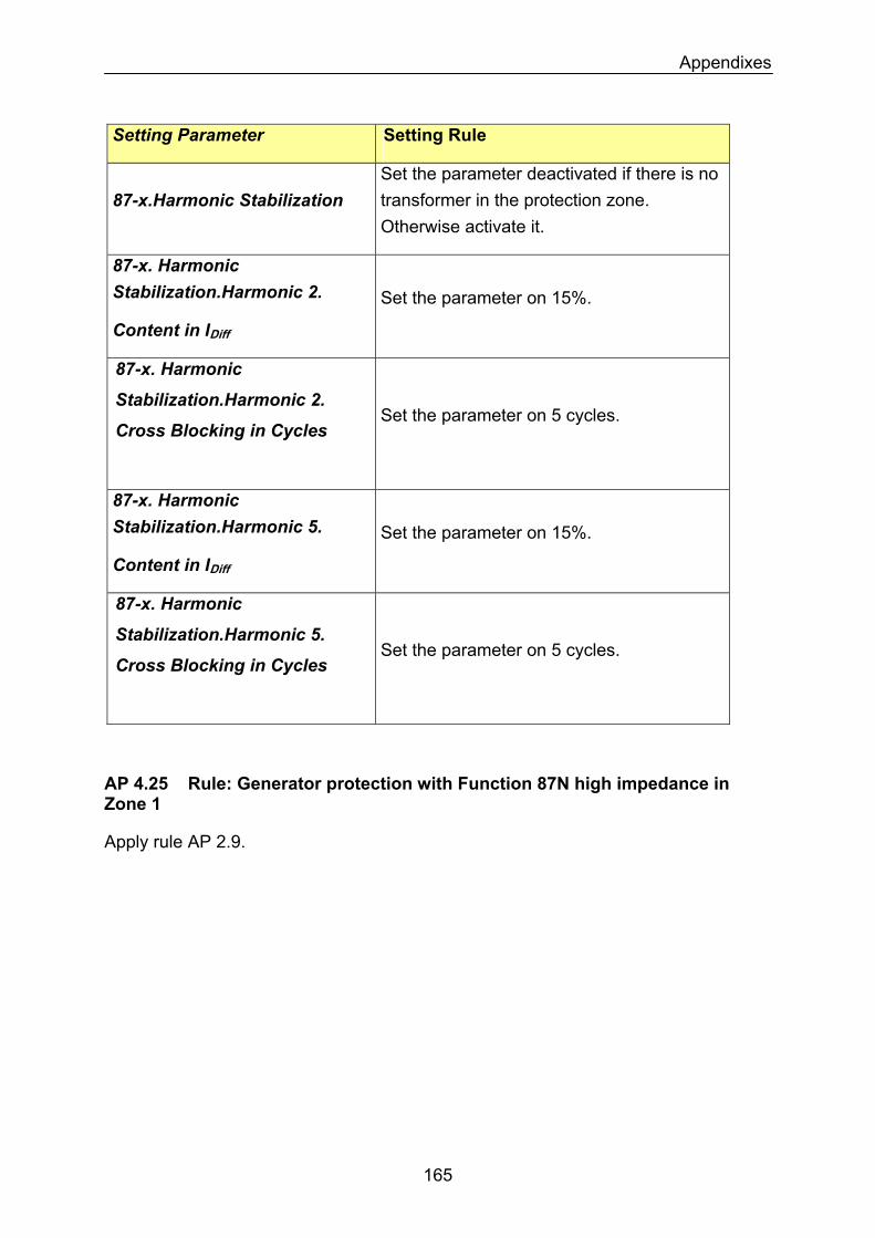
Appendixes
Setting Parameter Setting Rule
87-x.Harmonic Stabilization Set the parameter deactivated if there is no transformer in the protection zone. Otherwise activate it.
87-x. Harmonic Stabilization.Harmonic 2.
Content in IDiff
Set the parameter on 15%.
87-x. Harmonic
Stabilization.Harmonic 2. Set the parameter on 5 cycles.
Cross Blocking in Cycles
87-x. Harmonic Stabilization.Harmonic 5. Set the parameter on 15%.
Content in IDiff
87-x. Harmonic
Stabilization.Harmonic 5.
Cross Blocking in Cycles
Set the parameter on 5 cycles.
AP 4.25 Rule: Generator protection with Function 87N high impedance in Zone 1
Apply rule AP 2.9.
165
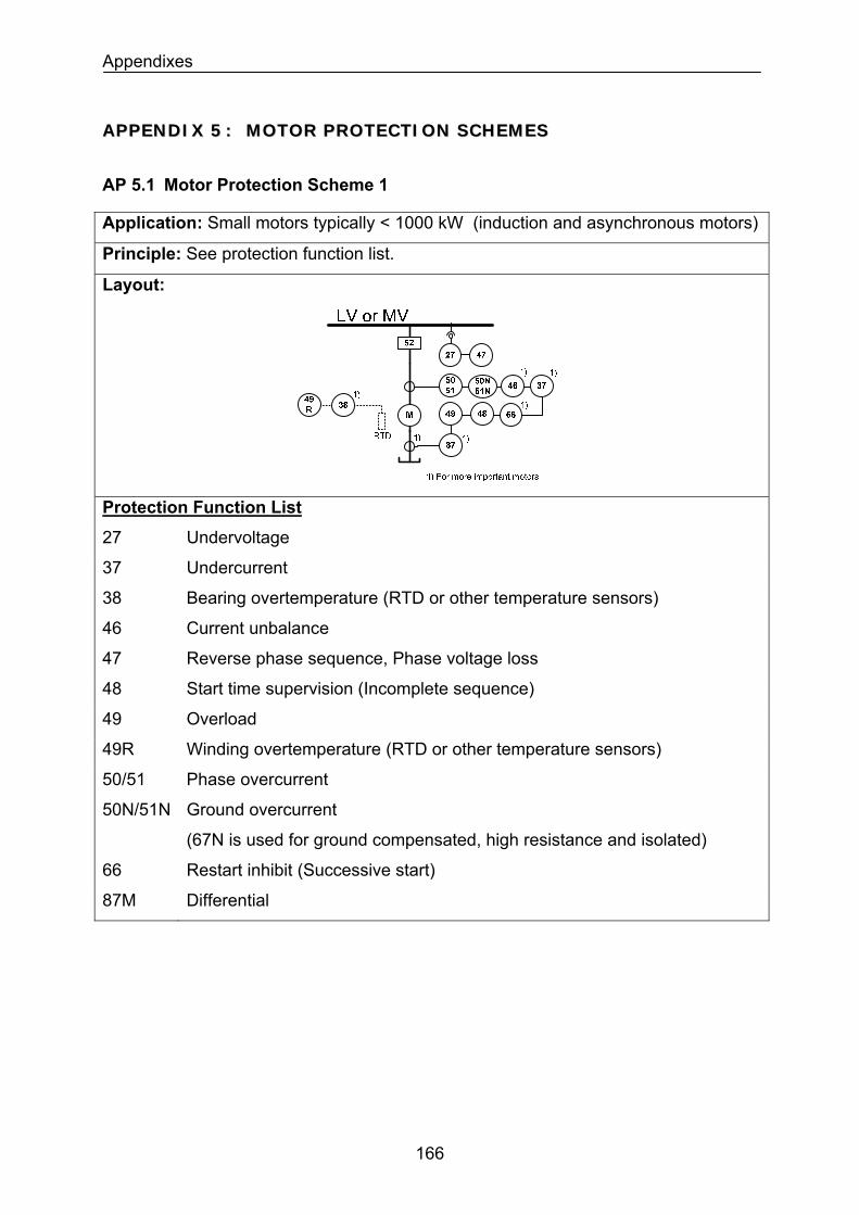
Appendixes
AAPPPPEENNDDIIXX 55 :: MMOOTTOORR PPRROOTTEECCTTIIOONN SSCCHHEEMMEESS
AP 5.1 Motor Protection Scheme 1
Application: Small motors typically < 1000 kW (induction and asynchronous motors)
Principle: See protection function list.
Layout:
Protection Function List
27 Undervoltage
37 Undercurrent
38 Bearing overtemperature (RTD or other temperature sensors)
46 Current unbalance
47 Reverse phase sequence, Phase voltage loss
48 Start time supervision (Incomplete sequence)
49 Overload
49R Winding overtemperature (RTD or other temperature sensors)
50/51 Phase overcurrent
50N/51N Ground overcurrent
(67N is used for ground compensated, high resistance and isolated)
66 Restart inhibit (Successive start)
87M Differential
166
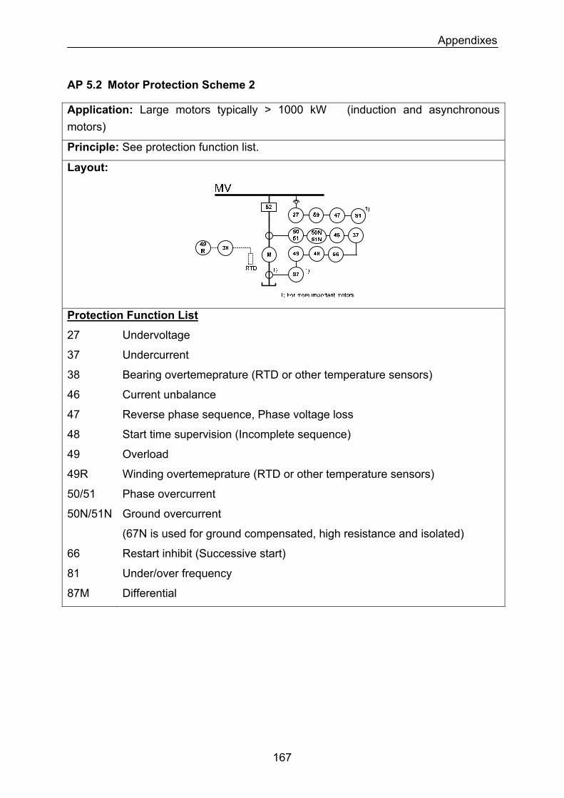
Appendixes
AP 5.2 Motor Protection Scheme 2
Application: Large motors typically > 1000 kW (induction and asynchronous motors)
Principle: See protection function list.
Layout:
Protection Function List
27 Undervoltage
37 Undercurrent
38 Bearing overtemeprature (RTD or other temperature sensors)
46 Current unbalance
47 Reverse phase sequence, Phase voltage loss
48 Start time supervision (Incomplete sequence)
49 Overload
49R Winding overtemeprature (RTD or other temperature sensors)
50/51 Phase overcurrent
50N/51N Ground overcurrent
(67N is used for ground compensated, high resistance and isolated)
66 Restart inhibit (Successive start)
81 Under/over frequency
87M Differential
167
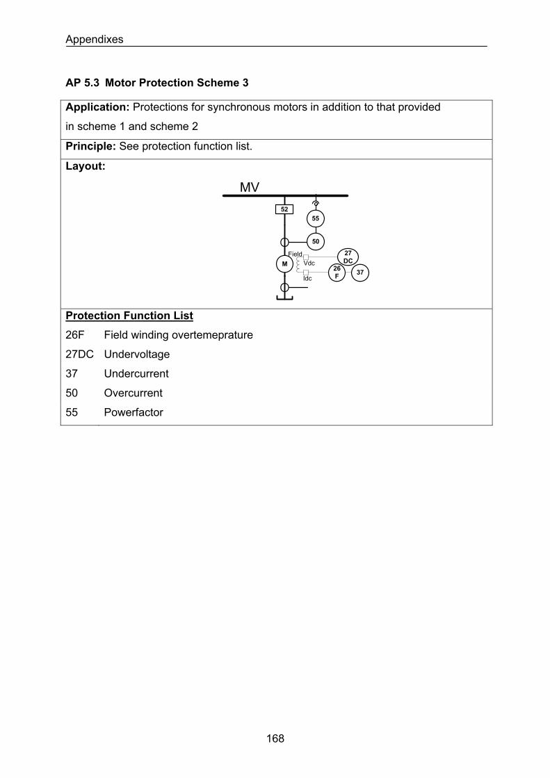
Appendixes
AP 5.3 Motor Protection Scheme 3
Application: Protections for synchronous motors in addition to that provided
in scheme 1 and scheme 2
Principle: See protection function list.
Layout:
MV
50
52
M
55
FieldVdc
Idc3726
F
27DC
Protection Function List
26F Field winding overtemeprature
27DC Undervoltage
37 Undercurrent
50 Overcurrent
55 Powerfactor
168
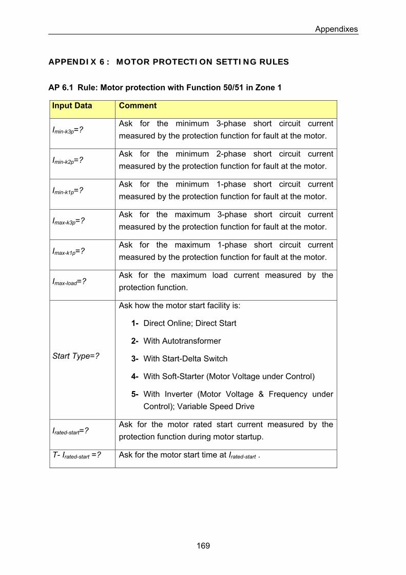
Appendixes
AAPPPPEENNDDIIXX 66 :: MMOOTTOORR PPRROOTTEECCTTIIOONN SSEETTTTIINNGG RRUULLEESS
AP 6.1 Rule: Motor protection with Function 50/51 in Zone 1
Input Data Comment
Imin-k3p=? Ask for the minimum 3-phase short circuit current measured by the protection function for fault at the motor.
Imin-k2p=? Ask for the minimum 2-phase short circuit current measured by the protection function for fault at the motor.
Imin-k1p=? Ask for the minimum 1-phase short circuit current measured by the protection function for fault at the motor.
Imax-k3p=? Ask for the maximum 3-phase short circuit current measured by the protection function for fault at the motor.
Ask for the maximum 1-phase short circuit current measured by the protection function for fault at the motor.
Imax-k1p=?
Ask for the maximum load current measured by the protection function.
Imax-load=?
Start Type=?
Ask how the motor start facility is:
1- Direct Online; Direct Start
2- With Autotransformer
3- With Start-Delta Switch
4- With Soft-Starter (Motor Voltage under Control)
5- With Inverter (Motor Voltage & Frequency under Control); Variable Speed Drive
Irated-start=? Ask for the motor rated start current measured by the protection function during motor startup.
T- Irated-start =? Ask for the motor start time at Irated-start .
169
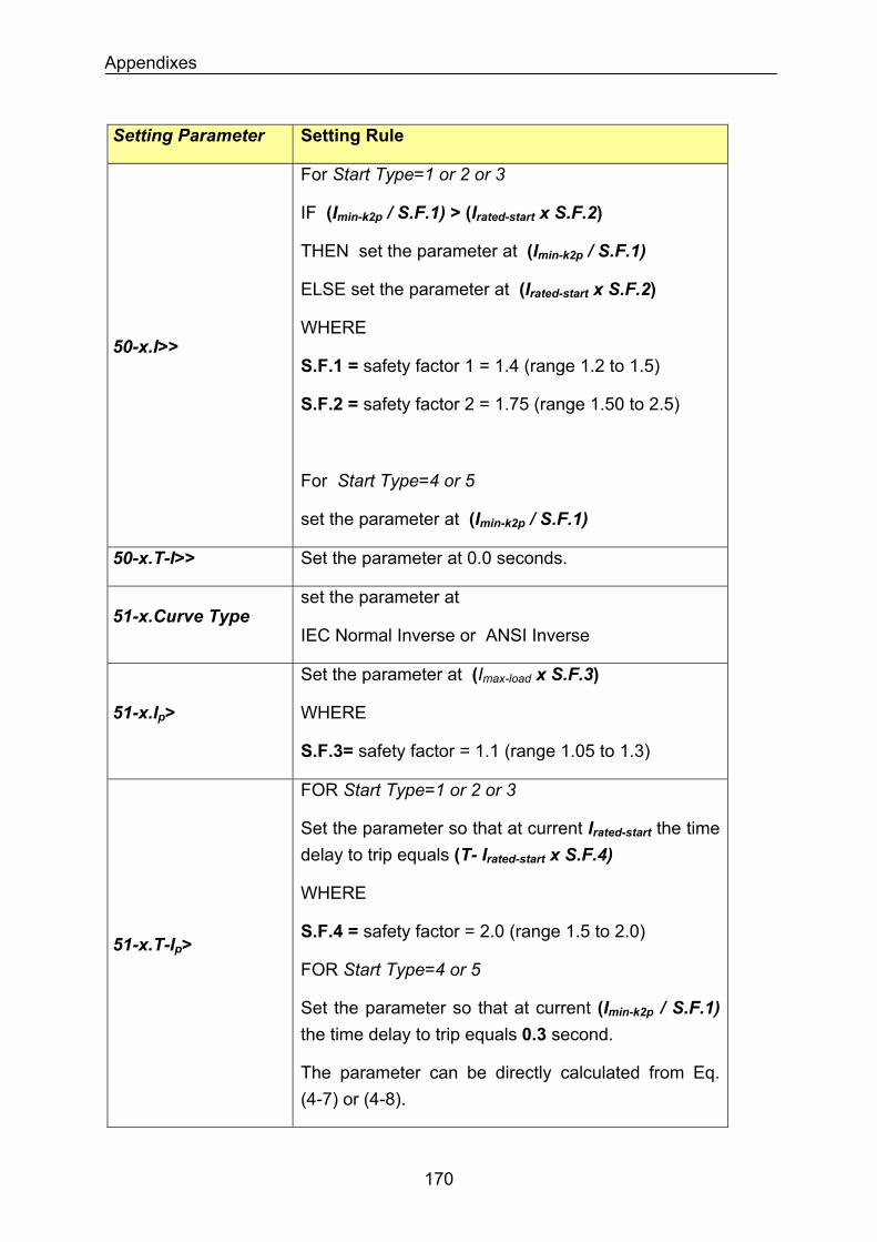
Appendixes
Setting Parameter Setting Rule
50-x.I>>
For Start Type=1 or 2 or 3
IF (Imin-k2p / S.F.1) > (Irated-start x S.F.2)
THEN set the parameter at (Imin-k2p / S.F.1)
ELSE set the parameter at (Irated-start x S.F.2)
WHERE
S.F.1 = safety factor 1 = 1.4 (range 1.2 to 1.5)
S.F.2 = safety factor 2 = 1.75 (range 1.50 to 2.5)
For Start Type=4 or 5
set the parameter at (Imin-k2p / S.F.1)
50-x.T-I>> Set the parameter at 0.0 seconds.
51-x.Curve Type set the parameter at
IEC Normal Inverse or ANSI Inverse
Set the parameter at (Imax-load x S.F.3)
WHERE 51-x.Ip>
S.F.3= safety factor = 1.1 (range 1.05 to 1.3)
FOR Start Type=1 or 2 or 3
Set the parameter so that at current Irated-start the time delay to trip equals (T- Irated-start x S.F.4)
WHERE
S.F.4 = safety factor = 2.0 (range 1.5 to 2.0) 51-x.T-Ip>
FOR Start Type=4 or 5
Set the parameter so that at current (Imin-k2p / S.F.1) the time delay to trip equals 0.3 second.
The parameter can be directly calculated from Eq. (4-7) or (4-8).
170
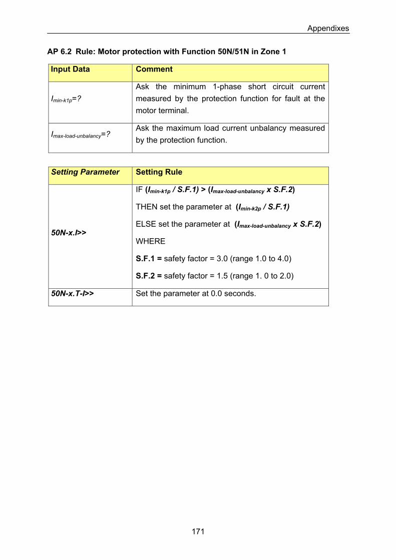
Appendixes
AP 6.2 Rule: Motor protection with Function 50N/51N in Zone 1
Input Data Comment
Imin-k1p=? Ask the minimum 1-phase short circuit current measured by the protection function for fault at the motor terminal.
Imax-load-unbalancy=? Ask the maximum load current unbalancy measured by the protection function.
Setting Parameter Setting Rule
IF (Imin-k1p / S.F.1) > (Imax-load-unbalancy x S.F.2)
THEN set the parameter at (Imin-k2p / S.F.1)
ELSE set the parameter at (Imax-load-unbalancy x S.F.2) 50N-x.I>>
WHERE
S.F.1 = safety factor = 3.0 (range 1.0 to 4.0)
S.F.2 = safety factor = 1.5 (range 1. 0 to 2.0)
50N-x.T-I>> Set the parameter at 0.0 seconds.
171
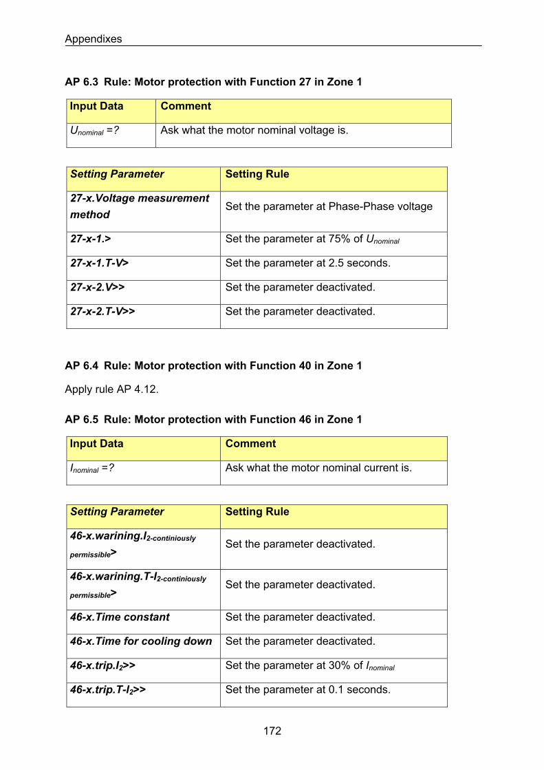
Appendixes
AP 6.3 Rule: Motor protection with Function 27 in Zone 1
Input Data Comment
Ask what the motor nominal voltage is. Unominal =?
Setting Parameter Setting Rule
27-x.Voltage measurement method
Set the parameter at Phase-Phase voltage
Set the parameter at 75% of Unominal27-x-1.>
Set the parameter at 2.5 seconds. 27-x-1.T-V>
Set the parameter deactivated. 27-x-2.V>>
Set the parameter deactivated. 27-x-2.T-V>>
AP 6.4 Rule: Motor protection with Function 40 in Zone 1
Apply rule AP 4.12.
AP 6.5 Rule: Motor protection with Function 46 in Zone 1
Input Data Comment
Ask what the motor nominal current is. Inominal =?
Setting Parameter Setting Rule
46-x.warining.I2-continiously
permissible> Set the parameter deactivated.
46-x.warining.T-I2-continiously
permissible> Set the parameter deactivated.
Set the parameter deactivated. 46-x.Time constant
Set the parameter deactivated. 46-x.Time for cooling down
Set the parameter at 30% of Inominal46-x.trip.I2>>
46-x.trip.T-I2>> Set the parameter at 0.1 seconds.
172
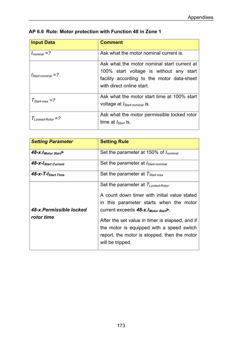
Appendixes
AP 6.6 Rule: Motor protection with Function 48 in Zone 1
Input Data Comment
Ask what the motor nominal current is. Inominal =?
Ask what the motor nominal start current at 100% start voltage is without any start facility according to the motor data-sheet with direct online start.
IStart-nominal =?
Ask what the motor start time at 100% start voltage at IStart-nominal is.
TStart-max =?
TLocked-Rotor =? Ask what the motor permissible locked rotor time at IStart is.
Setting Parameter Setting Rule
Set the parameter at 150% of Inominal48-x.IMotor Start>
Set the parameter at IStart-nominal48-x-IStart Current
Set the parameter at TStart-max48-x-T-IStart Time
Set the parameter at TLocked-Rotor.
A count down timer with initial value stated in this parameter starts when the motor current exceeds 48-x.IMotor Start>. 48-x.Permissible locked
rotor time After the set value in timer is elapsed, and if the motor is equipped with a speed switch report, the motor is stopped, then the motor will be tripped.
173
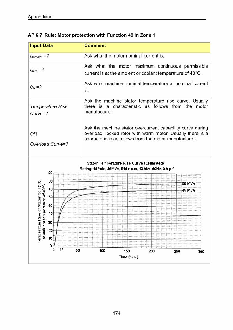
Appendixes
AP 6.7 Rule: Motor protection with Function 49 in Zone 1
Input Data Comment
Inominal =? Ask what the motor nominal current is.
Imax =? Ask what the motor maximum continuous permissible current is at the ambient or coolant temperature of 40°C.
Ask what machine nominal temperature at nominal current is.
θN =?
Temperature Rise Curve=?
OR
Overload Curve=?
Ask the machine stator temperature rise curve. Usually there is a characteristic as follows from the motor manufacturer. Ask the machine stator overcurrent capability curve during overload, locked rotor with warm motor. Usually there is a characteristic as follows from the motor manufacturer.
174
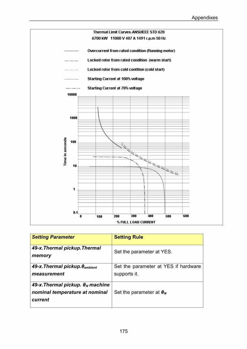
Appendixes
Setting Parameter Setting Rule
49-x.Thermal pickup.Thermal memory
Set the parameter at YES.
Set the parameter at YES if hardware supports it.
49-x.Thermal pickup.θambient measurement
49-x.Thermal pickup. θN machine nominal temperature at nominal current
Set the parameter at θN
175
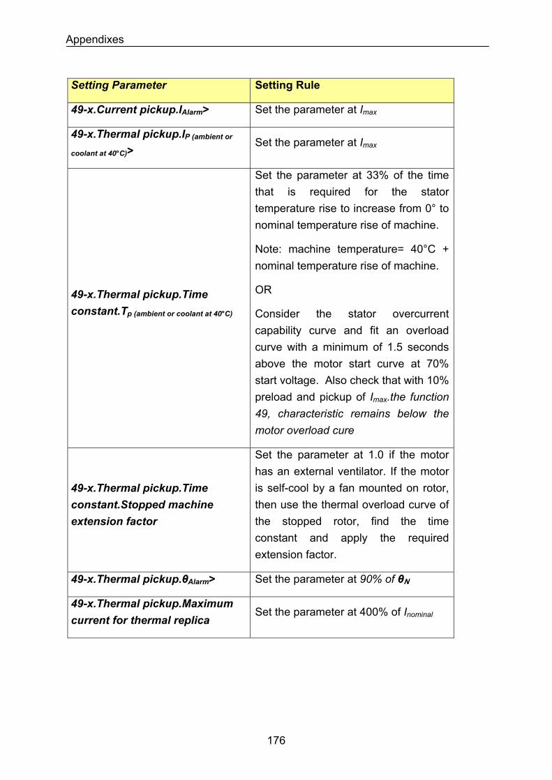
Appendixes
Setting Parameter Setting Rule
49-x.Current pickup.IAlarm> Set the parameter at Imax
49-x.Thermal pickup.IP (ambient or
coolant at 40°C)> Set the parameter at Imax
Set the parameter at 33% of the time that is required for the stator temperature rise to increase from 0° to nominal temperature rise of machine.
Note: machine temperature= 40°C + nominal temperature rise of machine.
49-x.Thermal pickup.Time constant.Tp (ambient or coolant at 40°C)
OR
Consider the stator overcurrent capability curve and fit an overload curve with a minimum of 1.5 seconds above the motor start curve at 70% start voltage. Also check that with 10% preload and pickup of Imax.the function 49, characteristic remains below the motor overload cure
49-x.Thermal pickup.Time constant.Stopped machine extension factor
Set the parameter at 1.0 if the motor has an external ventilator. If the motor is self-cool by a fan mounted on rotor, then use the thermal overload curve of the stopped rotor, find the time constant and apply the required extension factor.
Set the parameter at 90% of θN49-x.Thermal pickup.θAlarm>
49-x.Thermal pickup.Maximum current for thermal replica
Set the parameter at 400% of Inominal
176
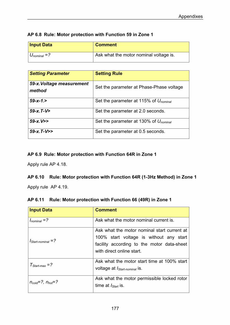
Appendixes
AP 6.8 Rule: Motor protection with Function 59 in Zone 1
Input Data Comment
Ask what the motor nominal voltage is. Unominal =?
Setting Parameter Setting Rule
59-x.Voltage measurement method
Set the parameter at Phase-Phase voltage
Set the parameter at 115% of Unominal59-x-1.>
59-x.T-V> Set the parameter at 2.0 seconds.
59-x.V>> Set the parameter at 130% of Unominal
59-x.T-V>> Set the parameter at 0.5 seconds.
AP 6.9 Rule: Motor protection with Function 64R in Zone 1
Apply rule AP 4.18.
AP 6.10 Rule: Motor protection with Function 64R (1-3Hz Method) in Zone 1
Apply rule AP 4.19.
AP 6.11 Rule: Motor protection with Function 66 (49R) in Zone 1
Input Data Comment
Ask what the motor nominal current is. Inominal =?
Ask what the motor nominal start current at 100% start voltage is without any start facility according to the motor data-sheet with direct online start.
IStart-nominal =?
Ask what the motor start time at 100% start voltage at IStart-nominal is.
TStart-max =?
Ask what the motor permissible locked rotor time at IStart is.
ncold=?, nhot=?
177
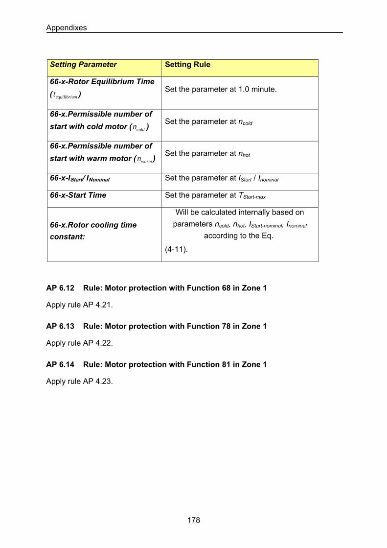
Appendixes
Setting Parameter Setting Rule
66-x-Rotor Equilibrium Time ( ) mequilibriut Set the parameter at 1.0 minute.
66-x.Permissible number of start with cold motor ( ) coldn Set the parameter at ncold
66-x.Permissible number of start with warm motor ( ) warmn Set the parameter at nhot
Set the parameter at IStart / Inominal66-x-IStart/ INominal
Set the parameter at TStart-max66-x-Start Time
Will be calculated internally based on parameters ncold, nhot, IStart-nominal, Inominal
according to the Eq. 66-x.Rotor cooling time constant:
(4-11).
AP 6.12 Rule: Motor protection with Function 68 in Zone 1
Apply rule AP 4.21.
AP 6.13 Rule: Motor protection with Function 78 in Zone 1
Apply rule AP 4.22.
AP 6.14 Rule: Motor protection with Function 81 in Zone 1
Apply rule AP 4.23.
178
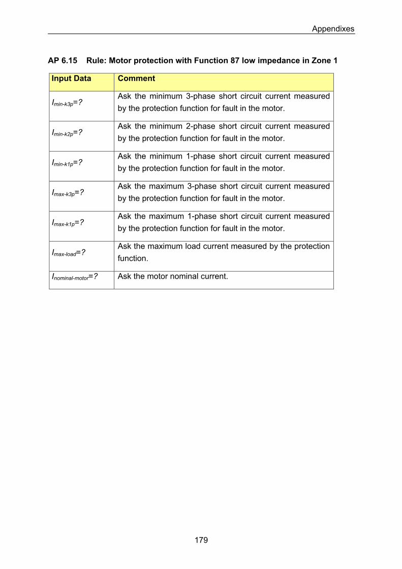
Appendixes
AP 6.15 Rule: Motor protection with Function 87 low impedance in Zone 1
Input Data Comment
Ask the minimum 3-phase short circuit current measured by the protection function for fault in the motor.
Imin-k3p=?
Ask the minimum 2-phase short circuit current measured by the protection function for fault in the motor.
Imin-k2p=?
Ask the minimum 1-phase short circuit current measured by the protection function for fault in the motor.
Imin-k1p=?
Ask the maximum 3-phase short circuit current measured by the protection function for fault in the motor.
Imax-k3p=?
Imax-k1p=? Ask the maximum 1-phase short circuit current measured by the protection function for fault in the motor.
Imax-load=? Ask the maximum load current measured by the protection function.
Ask the motor nominal current. Inominal-motor=?
179
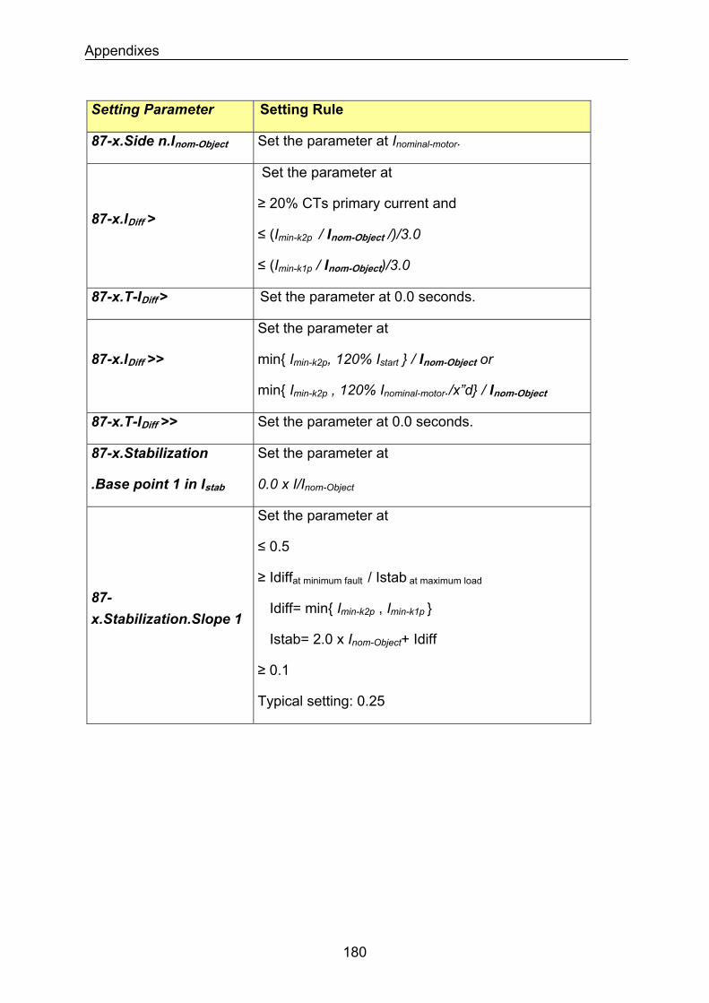
Appendixes
Setting Parameter Setting Rule
Set the parameter at Inominal-motor. 87-x.Side n.Inom-Object
87-x.IDiff >
Set the parameter at
≥ 20% CTs primary current and
≤ (Imin-k2p / Inom-Object /)/3.0
≤ (Imin-k1p / Inom-Object)/3.0
87-x.T-IDiff > Set the parameter at 0.0 seconds.
87-x.IDiff >>
Set the parameter at
min Imin-k2p, 120% Istart / Inom-Object or
min Imin-k2p , 120% Inominal-motor./x”d / Inom-Object
Set the parameter at 0.0 seconds. 87-x.T-IDiff >>
87-x.Stabilization
.Base point 1 in Istab
Set the parameter at
0.0 x I/Inom-Object
87-x.Stabilization.Slope 1
Set the parameter at
≤ 0.5
≥ Idiffat minimum fault / Istab at maximum load
Idiff= min Imin-k2p , Imin-k1p
Istab= 2.0 x Inom-Object+ Idiff
≥ 0.1
Typical setting: 0.25
180

Appendixes
Setting Parameter Setting Rule
87-x.Stabilization.Base point 2 in Istab
Set the parameter at
2.5 x I/Inom-Object
Ignore any trip by slope 2 as long as the sum of incoming current to bus is 125% Inom-Object. Above this setting, stabilize the differential protection against CT saturation for external faults.
87-x.Stabilization.Slope 2
Set the parameter at
≤ 0.95
≥ 0.25
≥ Idiff / (Istab - Base point 2 )
S.F.= Saturation Factor to one CT=
Idiff= S.F. x Imax-k3p / Inom-Object (blocking target)
Istab= 2.0 x Imax-k3p / Inom-Object
As an example: S.F.= 95%, Base Point 2 = 2.5
CT primary current = 2000 A, Imax-k3p = 40 kA
then Slope 2 ≥ 0.5
This settings block the operation of differential protection if an external fault with magnitude of Imax-
k3p happens and CTs at one feeder saturated so that the differential current around
95% of Imax-k3p/ Inom-Object is observed.
The setting can be more sensitive by reducing the saturation factor if an exact value from a simulation is available. By simulation, simultaneous saturation of CTs can also be evaluated.
181
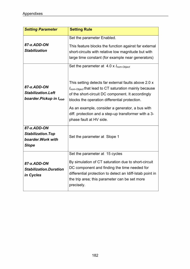
Appendixes
Setting Parameter Setting Rule
Set the parameter Enabled.
87-x.ADD-ON Stabilization
This feature blocks the function against far external short-circuits with relative low magnitude but with large time constant (for example near generators)
Set the parameter at 4.0 x Inom-Object
This setting detects far external faults above 2.0 x Inom-Object that lead to CT saturation mainly because of the short-circuit DC component. It accordingly blocks the operation differential protection.
87-x.ADD-ON Stabilization.Left boarder.Pickup in Istab
As an example, consider a generator, a bus with diff. protection and a step-up transformer with a 3-phase fault at HV side.
87-x.ADD-ON Stabilization.Top boarder.Work with Slope
Set the parameter at Slope 1
87-x.ADD-ON Stabilization.Duration in Cycles
Set the parameter at 15 cycles
By simulation of CT saturation due to short-circuit DC component and finding the time needed for differential protection to detect an Idiff-Istab point in the trip area; this parameter can be set more precisely.
182
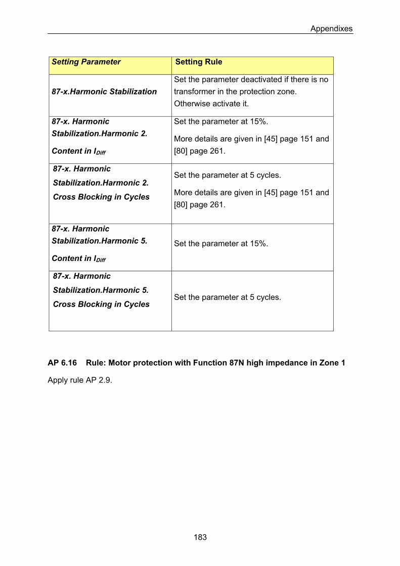
Appendixes
Setting Parameter Setting Rule
87-x.Harmonic Stabilization Set the parameter deactivated if there is no transformer in the protection zone. Otherwise activate it.
87-x. Harmonic Stabilization.Harmonic 2.
Content in IDiff
Set the parameter at 15%.
More details are given in [45] page 151 and [80] page 261.
87-x. Harmonic Set the parameter at 5 cycles.
Stabilization.Harmonic 2. More details are given in [45] page 151 and [80] page 261.
Cross Blocking in Cycles
87-x. Harmonic Stabilization.Harmonic 5. Set the parameter at 15%.
Content in IDiff
87-x. Harmonic
Stabilization.Harmonic 5.
Cross Blocking in Cycles
Set the parameter at 5 cycles.
AP 6.16 Rule: Motor protection with Function 87N high impedance in Zone 1
Apply rule AP 2.9.
183
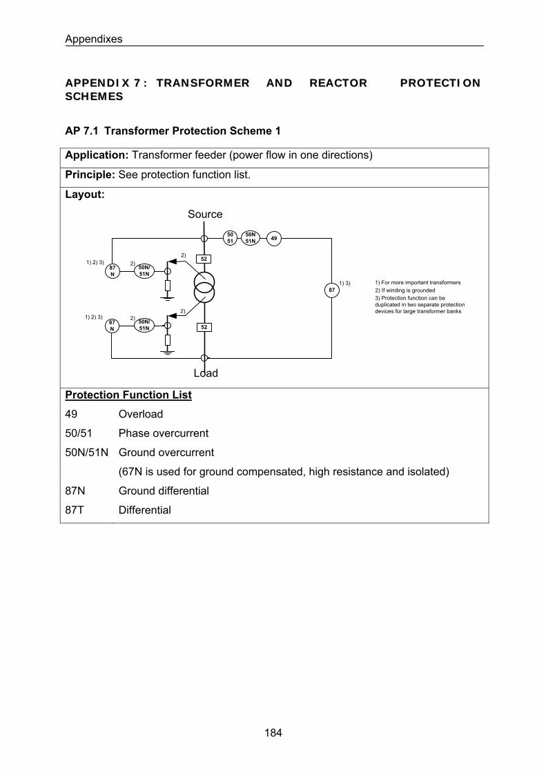
Appendixes
AAPPPPEENNDDIIXX 77 :: TTRRAANNSSFFOORRMMEERR AANNDD RREEAACCTTOORR PPRROOTTEECCTTIIOONN SSCCHHEEMMEESS
AP 7.1 Transformer Protection Scheme 1
Application: Transformer feeder (power flow in one directions)
Principle: See protection function list.
Layout:
5051
50N51N
52
Source
1)
1) 3) 1) For more important transformers
52
Load
87 2) If winding is grounded
49
3) Protection function can be duplicated in two separate protection devices for large transformer banks
2)1) 2) 3)
1) 2) 3)
50N/51N
87N
2)
50N/51N
87N
2)2)
Protection Function List
49 Overload
50/51 Phase overcurrent
50N/51N Ground overcurrent
(67N is used for ground compensated, high resistance and isolated)
87N Ground differential
87T Differential
184
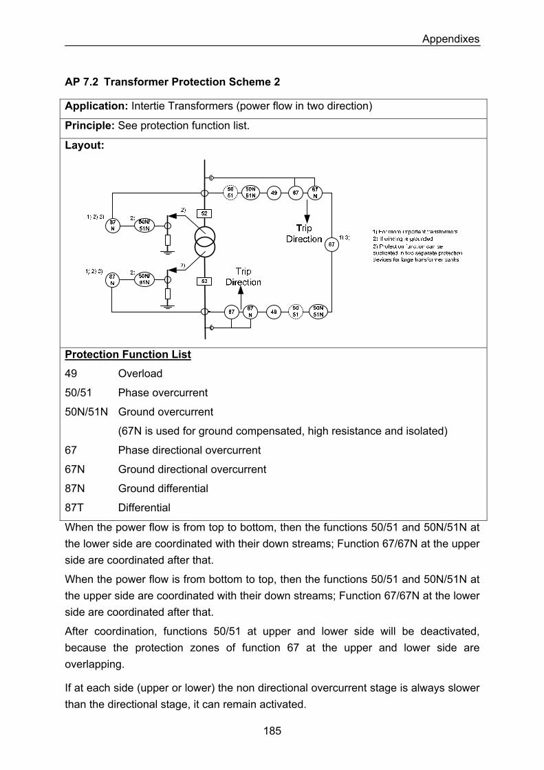
Appendixes
AP 7.2 Transformer Protection Scheme 2
Application: Intertie Transformers (power flow in two direction)
Principle: See protection function list.
Layout:
Protection Function List
49 Overload
50/51 Phase overcurrent
50N/51N Ground overcurrent
(67N is used for ground compensated, high resistance and isolated)
67 Phase directional overcurrent
67N Ground directional overcurrent
87N Ground differential
87T Differential
When the power flow is from top to bottom, then the functions 50/51 and 50N/51N at the lower side are coordinated with their down streams; Function 67/67N at the upper side are coordinated after that.
When the power flow is from bottom to top, then the functions 50/51 and 50N/51N at the upper side are coordinated with their down streams; Function 67/67N at the lower side are coordinated after that.
After coordination, functions 50/51 at upper and lower side will be deactivated, because the protection zones of function 67 at the upper and lower side are overlapping.
If at each side (upper or lower) the non directional overcurrent stage is always slower than the directional stage, it can remain activated.
185
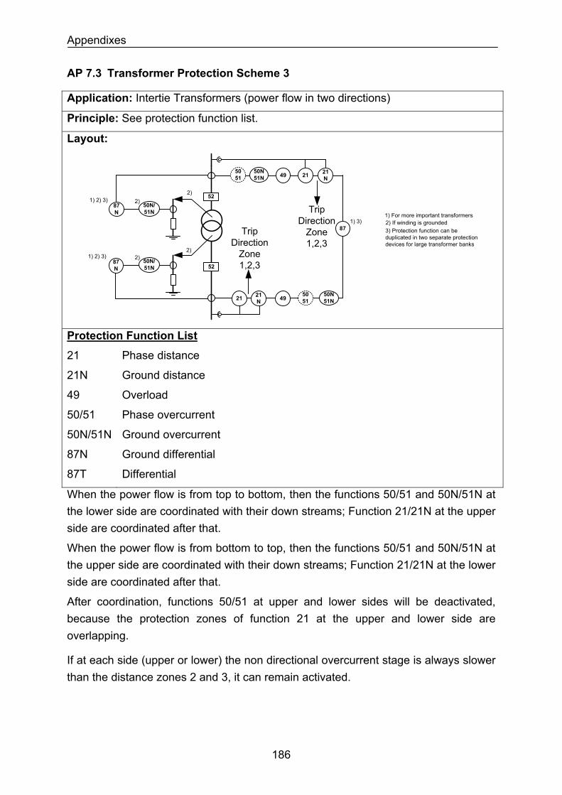
Appendixes
AP 7.3 Transformer Protection Scheme 3
Application: Intertie Transformers (power flow in two directions)
Principle: See protection function list.
Layout:
5051
50N51N
52
1)
1) 3)1) For more important transformers
52
872) If winding is grounded
49
3) Protection function can be duplicated in two separate protection devices for large transformer banks
21 21N
5051
50N51N4921
N21
2)1) 2) 3)
1) 2) 3)
50N/51N
87N
2)
50N/51N
87N
2)2)
Trip Direction
Zone 1,2,3
Trip Direction
Zone 1,2,3
Protection Function List
21 Phase distance
21N Ground distance
49 Overload
50/51 Phase overcurrent
50N/51N Ground overcurrent
87N Ground differential
87T Differential
When the power flow is from top to bottom, then the functions 50/51 and 50N/51N at the lower side are coordinated with their down streams; Function 21/21N at the upper side are coordinated after that.
When the power flow is from bottom to top, then the functions 50/51 and 50N/51N at the upper side are coordinated with their down streams; Function 21/21N at the lower side are coordinated after that.
After coordination, functions 50/51 at upper and lower sides will be deactivated, because the protection zones of function 21 at the upper and lower side are overlapping.
If at each side (upper or lower) the non directional overcurrent stage is always slower than the distance zones 2 and 3, it can remain activated.
186
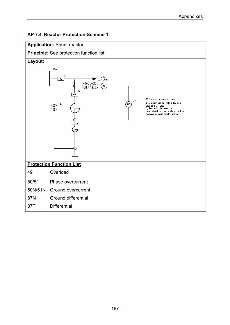
Appendixes
AP 7.4 Reactor Protection Scheme 1
Application: Shunt reactor
Principle: See protection function list.
Layout:
Protection Function List
49 Overload
50/51 Phase overcurrent
50N/51N Ground overcurrent
87N Ground differential
87T Differential
187
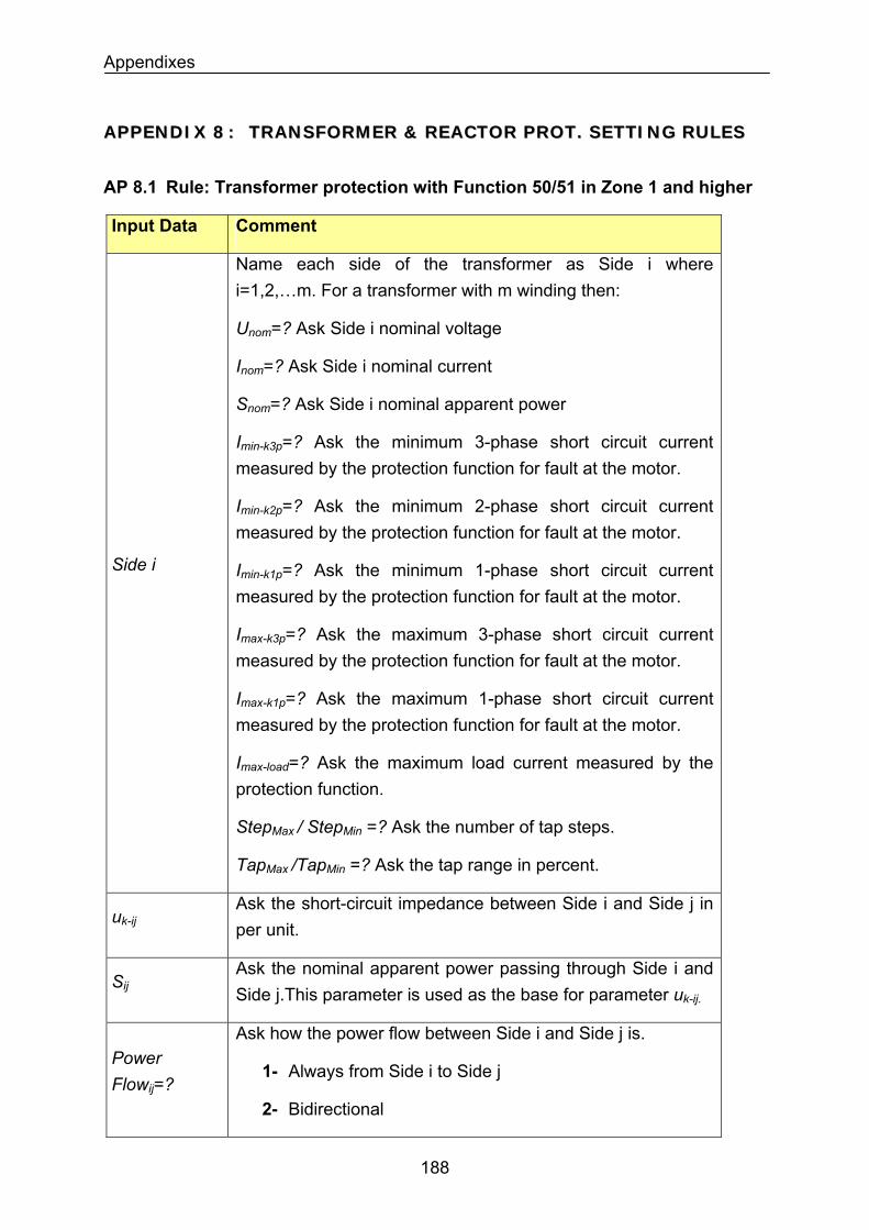
Appendixes
AAPPPPEENNDDIIXX 88 :: TTRRAANNSSFFOORRMMEERR && RREEAACCTTOORR PPRROOTT.. SSEETTTTIINNGG RRUULLEESS
AP 8.1 Rule: Transformer protection with Function 50/51 in Zone 1 and higher
Input Data Comment
Name each side of the transformer as Side i where i=1,2,…m. For a transformer with m winding then:
Unom=? Ask Side i nominal voltage
Inom=? Ask Side i nominal current
Snom=? Ask Side i nominal apparent power
Imin-k3p=? Ask the minimum 3-phase short circuit current measured by the protection function for fault at the motor.
Imin-k2p=? Ask the minimum 2-phase short circuit current measured by the protection function for fault at the motor.
Imin-k1p=? Ask the minimum 1-phase short circuit current measured by the protection function for fault at the motor.
Side i
Imax-k3p=? Ask the maximum 3-phase short circuit current measured by the protection function for fault at the motor.
Imax-k1p=? Ask the maximum 1-phase short circuit current measured by the protection function for fault at the motor.
Imax-load=? Ask the maximum load current measured by the protection function.
StepMax / StepMin =? Ask the number of tap steps.
TapMax /TapMin =? Ask the tap range in percent.
Ask the short-circuit impedance between Side i and Side j in per unit.
uk-ij
SijAsk the nominal apparent power passing through Side i and Side j.This parameter is used as the base for parameter uk-ij.
Power Flowij=?
Ask how the power flow between Side i and Side j is.
1- Always from Side i to Side j
2- Bidirectional
188
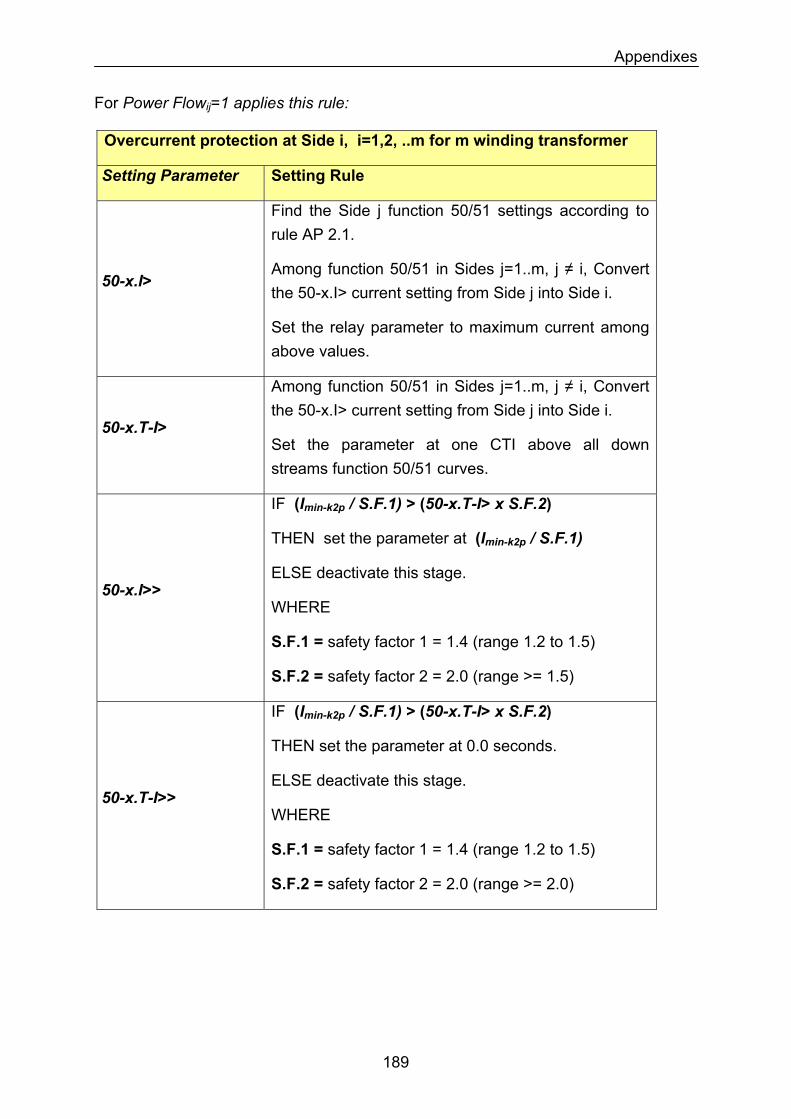
Appendixes
For Power Flowij=1 applies this rule:
Overcurrent protection at Side i, i=1,2, ..m for m winding transformer
Setting Parameter Setting Rule
50-x.I>
Find the Side j function 50/51 settings according to rule AP 2.1.
Among function 50/51 in Sides j=1..m, j ≠ i, Convert the 50-x.I> current setting from Side j into Side i.
Set the relay parameter to maximum current among above values.
50-x.T-I>
Among function 50/51 in Sides j=1..m, j ≠ i, Convert the 50-x.I> current setting from Side j into Side i.
Set the parameter at one CTI above all down streams function 50/51 curves.
IF (Imin-k2p / S.F.1) > (50-x.T-I> x S.F.2)
THEN set the parameter at (Imin-k2p / S.F.1)
ELSE deactivate this stage.
WHERE 50-x.I>>
S.F.1 = safety factor 1 = 1.4 (range 1.2 to 1.5)
S.F.2 = safety factor 2 = 2.0 (range >= 1.5)
50-x.T-I>>
IF (Imin-k2p / S.F.1) > (50-x.T-I> x S.F.2)
THEN set the parameter at 0.0 seconds.
ELSE deactivate this stage.
WHERE
S.F.1 = safety factor 1 = 1.4 (range 1.2 to 1.5)
S.F.2 = safety factor 2 = 2.0 (range >= 2.0)
189
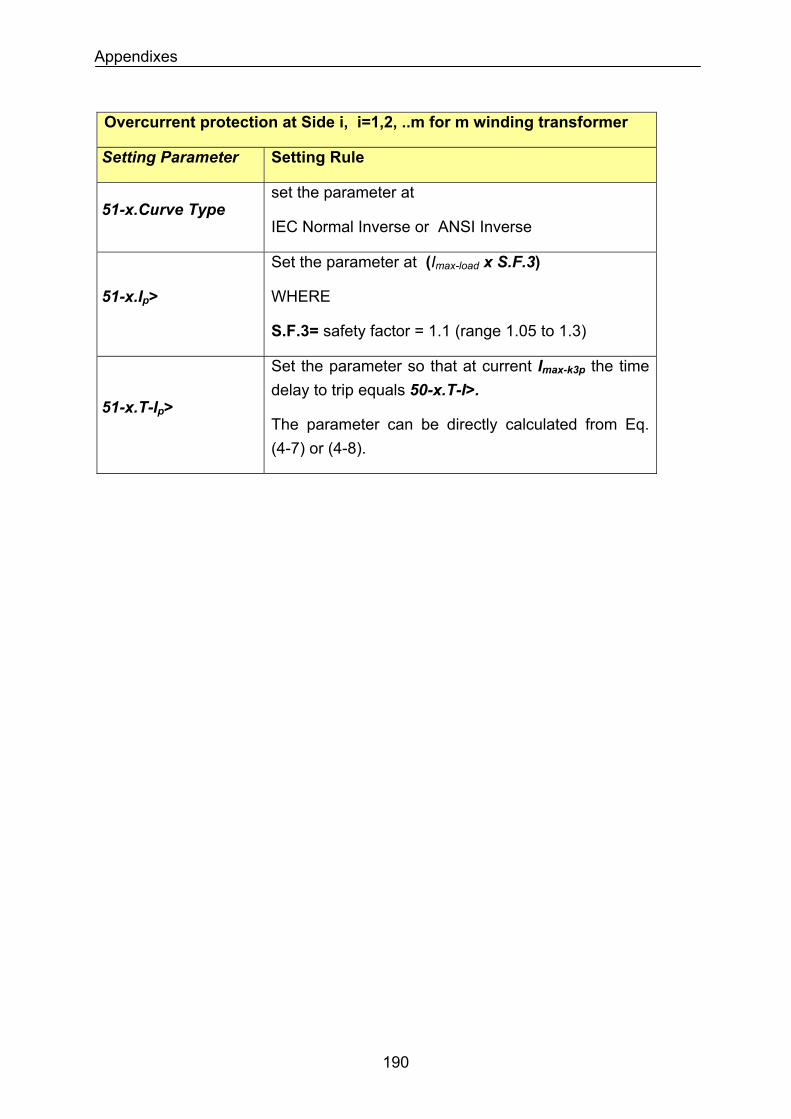
Appendixes
Overcurrent protection at Side i, i=1,2, ..m for m winding transformer
Setting Parameter Setting Rule
set the parameter at 51-x.Curve Type
IEC Normal Inverse or ANSI Inverse
Set the parameter at (Imax-load x S.F.3)
WHERE 51-x.Ip>
S.F.3= safety factor = 1.1 (range 1.05 to 1.3)
Set the parameter so that at current Imax-k3p the time delay to trip equals 50-x.T-I>.
51-x.T-Ip> The parameter can be directly calculated from Eq. (4-7) or (4-8).
190
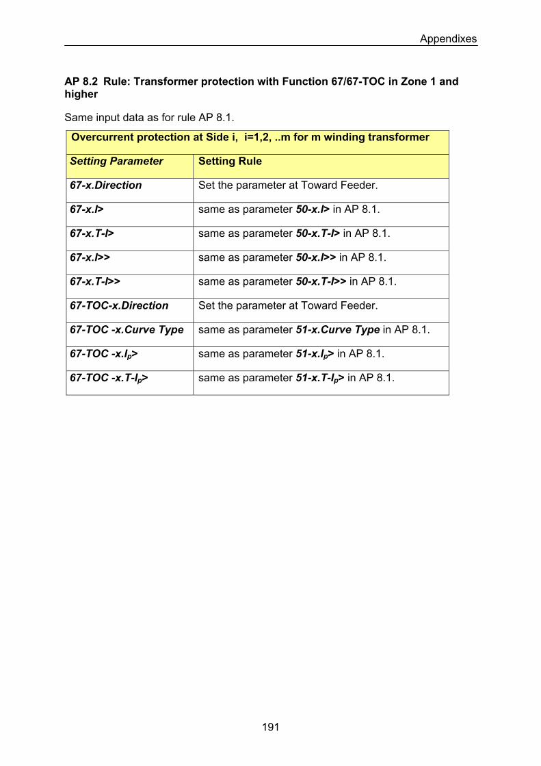
Appendixes
AP 8.2 Rule: Transformer protection with Function 67/67-TOC in Zone 1 and higher
Same input data as for rule AP 8.1.
Overcurrent protection at Side i, i=1,2, ..m for m winding transformer
Setting Parameter Setting Rule
Set the parameter at Toward Feeder. 67-x.Direction
same as parameter 50-x.I> in AP 8.1. 67-x.I>
same as parameter 50-x.T-I> in AP 8.1. 67-x.T-I>
same as parameter 50-x.I>> in AP 8.1. 67-x.I>>
same as parameter 50-x.T-I>> in AP 8.1. 67-x.T-I>>
67-TOC-x.Direction Set the parameter at Toward Feeder.
67-TOC -x.Curve Type same as parameter 51-x.Curve Type in AP 8.1.
67-TOC -x.Ip> same as parameter 51-x.Ip> in AP 8.1.
same as parameter 51-x.T-Ip> in AP 8.1. 67-TOC -x.T-Ip>
191
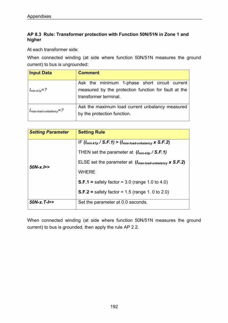
Appendixes
AP 8.3 Rule: Transformer protection with Function 50N/51N in Zone 1 and higher
At each transformer side:
When connected winding (at side where function 50N/51N measures the ground current) to bus is ungrounded:
Input Data Comment
Imin-k1p=? Ask the minimum 1-phase short circuit current measured by the protection function for fault at the transformer terminal.
Ask the maximum load current unbalancy measured by the protection function.
Imax-load-unbalancy=?
Setting Parameter Setting Rule
50N-x.I>>
IF (Imin-k1p / S.F.1) > (Imax-load-unbalancy x S.F.2)
THEN set the parameter at (Imin-k2p / S.F.1)
ELSE set the parameter at (Imax-load-unbalancy x S.F.2)
WHERE
S.F.1 = safety factor = 3.0 (range 1.0 to 4.0)
S.F.2 = safety factor = 1.5 (range 1. 0 to 2.0)
Set the parameter at 0.0 seconds. 50N-x.T-I>>
When connected winding (at side where function 50N/51N measures the ground current) to bus is grounded, then apply the rule AP 2.2.
192
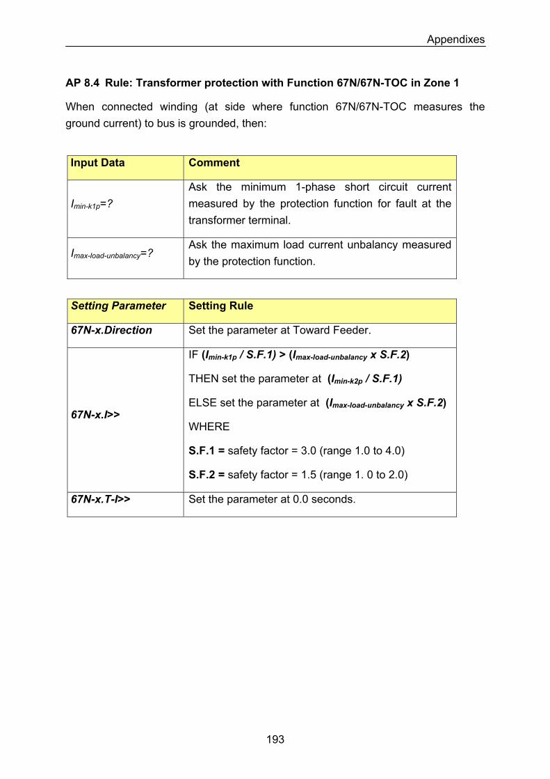
Appendixes
AP 8.4 Rule: Transformer protection with Function 67N/67N-TOC in Zone 1
When connected winding (at side where function 67N/67N-TOC measures the ground current) to bus is grounded, then:
Input Data Comment
Imin-k1p=? Ask the minimum 1-phase short circuit current measured by the protection function for fault at the transformer terminal.
Imax-load-unbalancy=? Ask the maximum load current unbalancy measured by the protection function.
Setting Parameter Setting Rule
67N-x.Direction Set the parameter at Toward Feeder.
67N-x.I>>
IF (Imin-k1p / S.F.1) > (Imax-load-unbalancy x S.F.2)
THEN set the parameter at (Imin-k2p / S.F.1)
ELSE set the parameter at (Imax-load-unbalancy x S.F.2)
WHERE
S.F.1 = safety factor = 3.0 (range 1.0 to 4.0)
S.F.2 = safety factor = 1.5 (range 1. 0 to 2.0)
67N-x.T-I>> Set the parameter at 0.0 seconds.
193
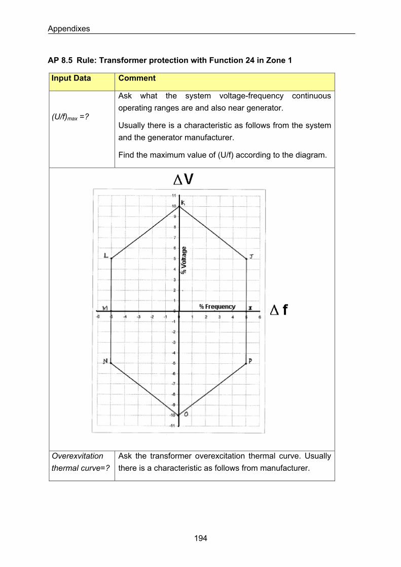
Appendixes
AP 8.5 Rule: Transformer protection with Function 24 in Zone 1
Input Data Comment
Ask what the system voltage-frequency continuous operating ranges are and also near generator.
(U/f)max =?
Usually there is a characteristic as follows from the system and the generator manufacturer.
Find the maximum value of (U/f) according to the diagram.
Overexvitation thermal curve=?
Ask the transformer overexcitation thermal curve. Usually there is a characteristic as follows from manufacturer.
194
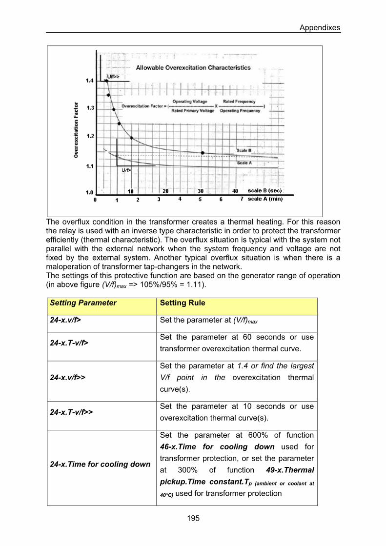
Appendixes
The overflux condition in the transformer creates a thermal heating. For this reason the relay is used with an inverse type characteristic in order to protect the transformer efficiently (thermal characteristic). The overflux situation is typical with the system not parallel with the external network when the system frequency and voltage are not fixed by the external system. Another typical overflux situation is when there is a maloperation of transformer tap-changers in the network. The settings of this protective function are based on the generator range of operation (in above figure (V/f)max => 105%/95% = 1.11). Setting Parameter Setting Rule
24-x.v/f> Set the parameter at (V/f)max
24-x.T-v/f> Set the parameter at 60 seconds or use transformer overexcitation thermal curve.
24-x.v/f>> Set the parameter at 1.4 or find the largest V/f point in the overexcitation thermal curve(s).
24-x.T-v/f>> Set the parameter at 10 seconds or use overexcitation thermal curve(s).
24-x.Time for cooling down
Set the parameter at 600% of function 46-x.Time for cooling down used for transformer protection, or set the parameter at 300% of function 49-x.Thermal pickup.Time constant.Tp (ambient or coolant at
40°C) used for transformer protection
195
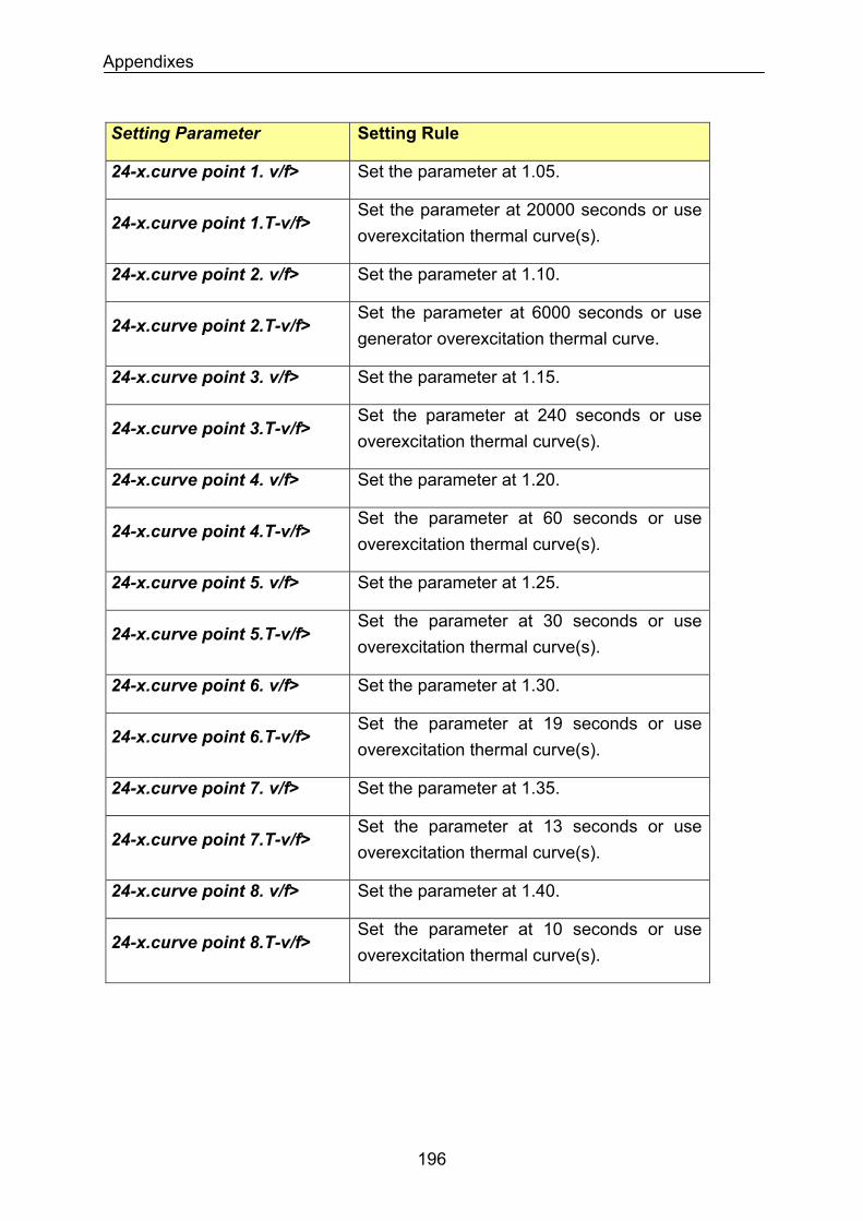
Appendixes
Setting Parameter Setting Rule
Set the parameter at 1.05. 24-x.curve point 1. v/f>
Set the parameter at 20000 seconds or use overexcitation thermal curve(s).
24-x.curve point 1.T-v/f>
Set the parameter at 1.10. 24-x.curve point 2. v/f>
Set the parameter at 6000 seconds or use generator overexcitation thermal curve.
24-x.curve point 2.T-v/f>
Set the parameter at 1.15. 24-x.curve point 3. v/f>
Set the parameter at 240 seconds or use overexcitation thermal curve(s).
24-x.curve point 3.T-v/f>
Set the parameter at 1.20. 24-x.curve point 4. v/f>
Set the parameter at 60 seconds or use overexcitation thermal curve(s).
24-x.curve point 4.T-v/f>
Set the parameter at 1.25. 24-x.curve point 5. v/f>
Set the parameter at 30 seconds or use overexcitation thermal curve(s).
24-x.curve point 5.T-v/f>
Set the parameter at 1.30. 24-x.curve point 6. v/f>
Set the parameter at 19 seconds or use overexcitation thermal curve(s).
24-x.curve point 6.T-v/f>
Set the parameter at 1.35. 24-x.curve point 7. v/f>
Set the parameter at 13 seconds or use overexcitation thermal curve(s).
24-x.curve point 7.T-v/f>
Set the parameter at 1.40. 24-x.curve point 8. v/f>
Set the parameter at 10 seconds or use overexcitation thermal curve(s).
24-x.curve point 8.T-v/f>
196
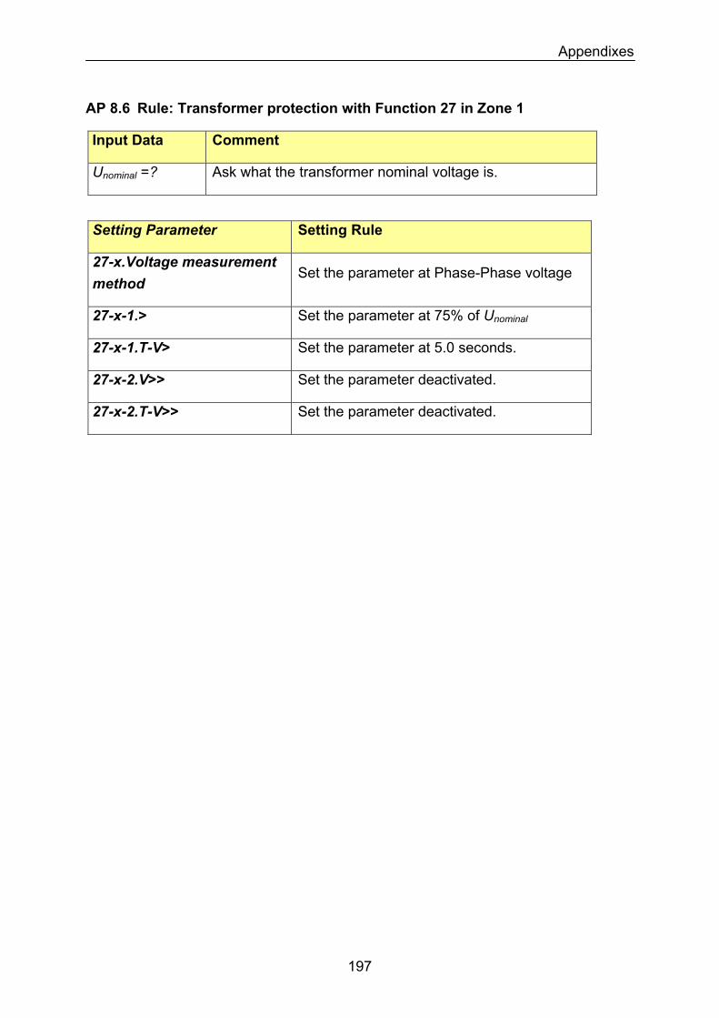
Appendixes
AP 8.6 Rule: Transformer protection with Function 27 in Zone 1
Input Data Comment
Unominal =? Ask what the transformer nominal voltage is.
Setting Parameter Setting Rule
27-x.Voltage measurement method
Set the parameter at Phase-Phase voltage
Set the parameter at 75% of Unominal27-x-1.>
Set the parameter at 5.0 seconds. 27-x-1.T-V>
Set the parameter deactivated. 27-x-2.V>>
27-x-2.T-V>> Set the parameter deactivated.
197
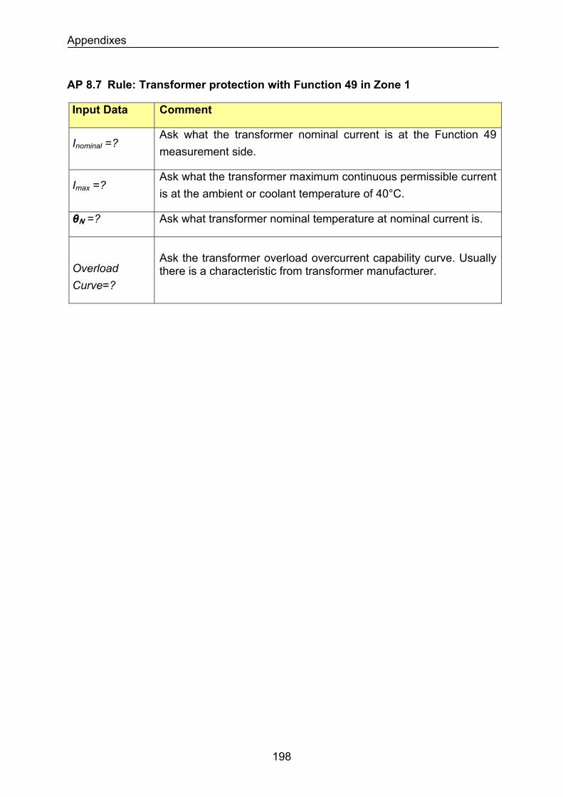
Appendixes
AP 8.7 Rule: Transformer protection with Function 49 in Zone 1
Input Data Comment
Ask what the transformer nominal current is at the Function 49 measurement side.
Inominal =?
Ask what the transformer maximum continuous permissible current is at the ambient or coolant temperature of 40°C.
Imax =?
Ask what transformer nominal temperature at nominal current is. θN =?
Overload Curve=?
Ask the transformer overload overcurrent capability curve. Usually there is a characteristic from transformer manufacturer.
198
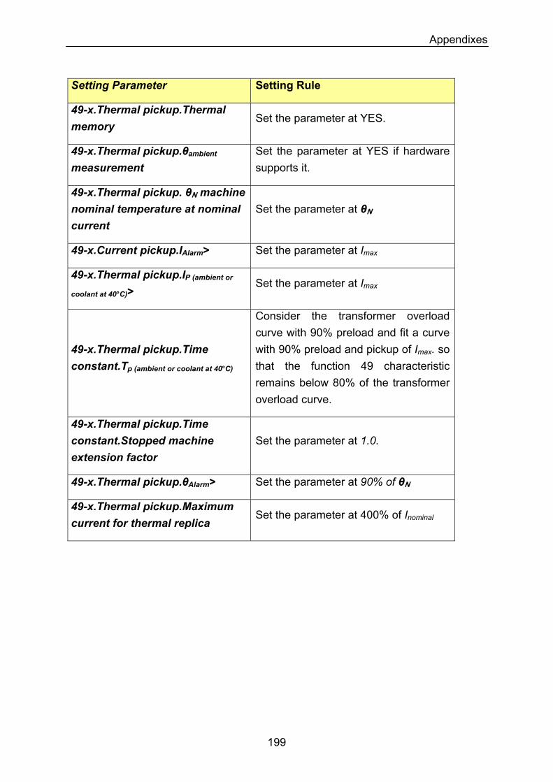
Appendixes
Setting Parameter Setting Rule
49-x.Thermal pickup.Thermal memory
Set the parameter at YES.
Set the parameter at YES if hardware supports it.
49-x.Thermal pickup.θambient measurement
49-x.Thermal pickup. θN machine nominal temperature at nominal current
Set the parameter at θN
Set the parameter at Imax49-x.Current pickup.IAlarm>
49-x.Thermal pickup.IP (ambient or
coolant at 40°C)> Set the parameter at Imax
Consider the transformer overload curve with 90% preload and fit a curve with 90% preload and pickup of Imax. so that the function 49 characteristic remains below 80% of the transformer overload curve.
49-x.Thermal pickup.Time constant.Tp (ambient or coolant at 40°C)
49-x.Thermal pickup.Time constant.Stopped machine extension factor
Set the parameter at 1.0.
Set the parameter at 90% of θN49-x.Thermal pickup.θAlarm>
49-x.Thermal pickup.Maximum current for thermal replica
Set the parameter at 400% of Inominal
199
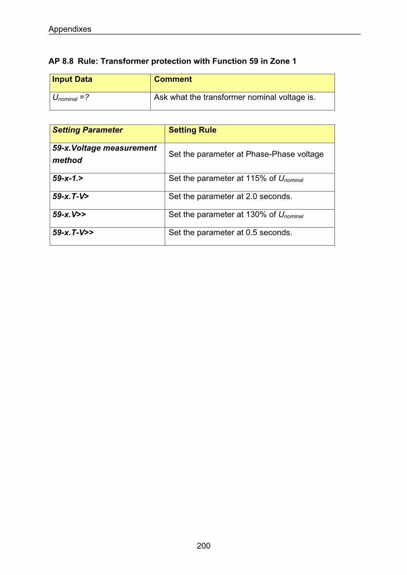
Appendixes
AP 8.8 Rule: Transformer protection with Function 59 in Zone 1
Input Data Comment
Unominal =? Ask what the transformer nominal voltage is.
Setting Parameter Setting Rule
59-x.Voltage measurement method
Set the parameter at Phase-Phase voltage
Set the parameter at 115% of Unominal59-x-1.>
59-x.T-V> Set the parameter at 2.0 seconds.
59-x.V>> Set the parameter at 130% of Unominal
59-x.T-V>> Set the parameter at 0.5 seconds.
200
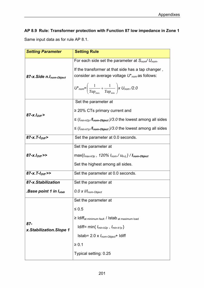
Appendixes
AP 8.9 Rule: Transformer protection with Function 87 low impedance in Zone 1
Same input data as for rule AP 8.1.
Setting Parameter Setting Rule
87-x.Side n.Inom-Object
For each side set the parameter at Snom/ Unom.
If the transformer at that side has a tap changer , consider an average voltage U*nom as follows:
U*nom= ⎟⎟⎠
⎞⎜⎜⎝
⎛+
minmax
11TapTap
x Unom /2.0
87-x.IDiff >
Set the parameter at
≥ 20% CTs primary current and
≤ (Imin-k2p /Inom-Object )/3.0 the lowest among all sides
≤ (Imin-k1p /Inom-Object )/3.0 the lowest among all sides
87-x.T-IDiff > Set the parameter at 0.0 seconds.
87-x.IDiff >>
Set the parameter at
maxImax-k3p , 120% Inom./ uk-ij / Inom-Object
Set the highest among all sides.
Set the parameter at 0.0 seconds. 87-x.T-IDiff >>
87-x.Stabilization
.Base point 1 in Istab
Set the parameter at
0.0 x I/Inom-Object
87-x.Stabilization.Slope 1
Set the parameter at
≤ 0.5
≥ Idiffat minimum fault / Istab at maximum load
Idiff= min Imin-k2p , Imin-k1p
Istab= 2.0 x Inom-Object+ Idiff
≥ 0.1
Typical setting: 0.25
201
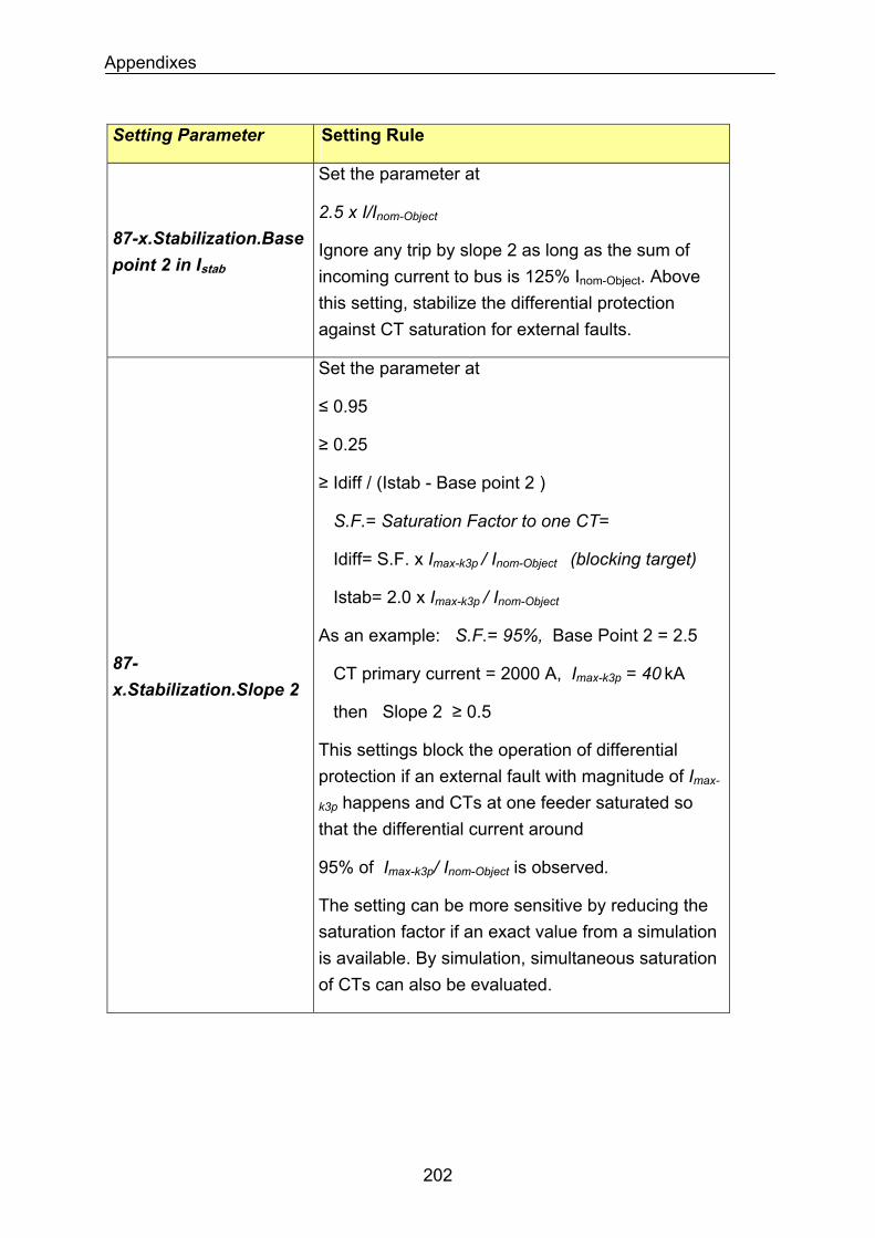
Appendixes
Setting Parameter Setting Rule
87-x.Stabilization.Base point 2 in Istab
Set the parameter at
2.5 x I/Inom-Object
Ignore any trip by slope 2 as long as the sum of incoming current to bus is 125% Inom-Object. Above this setting, stabilize the differential protection against CT saturation for external faults.
87-x.Stabilization.Slope 2
Set the parameter at
≤ 0.95
≥ 0.25
≥ Idiff / (Istab - Base point 2 )
S.F.= Saturation Factor to one CT=
Idiff= S.F. x Imax-k3p / Inom-Object (blocking target)
Istab= 2.0 x Imax-k3p / Inom-Object
As an example: S.F.= 95%, Base Point 2 = 2.5
CT primary current = 2000 A, Imax-k3p = 40 kA
then Slope 2 ≥ 0.5
This settings block the operation of differential protection if an external fault with magnitude of Imax-
k3p happens and CTs at one feeder saturated so that the differential current around
95% of Imax-k3p/ Inom-Object is observed.
The setting can be more sensitive by reducing the saturation factor if an exact value from a simulation is available. By simulation, simultaneous saturation of CTs can also be evaluated.
202
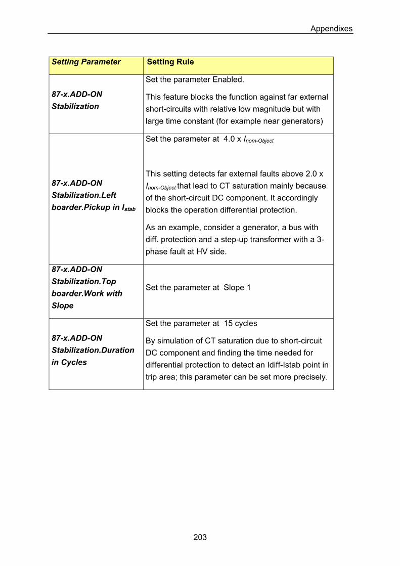
Appendixes
Setting Parameter Setting Rule
Set the parameter Enabled.
87-x.ADD-ON Stabilization
This feature blocks the function against far external short-circuits with relative low magnitude but with large time constant (for example near generators)
Set the parameter at 4.0 x Inom-Object
This setting detects far external faults above 2.0 x Inom-Object that lead to CT saturation mainly because of the short-circuit DC component. It accordingly blocks the operation differential protection.
87-x.ADD-ON Stabilization.Left boarder.Pickup in Istab
As an example, consider a generator, a bus with diff. protection and a step-up transformer with a 3-phase fault at HV side.
87-x.ADD-ON Stabilization.Top boarder.Work with Slope
Set the parameter at Slope 1
87-x.ADD-ON Stabilization.Duration in Cycles
Set the parameter at 15 cycles
By simulation of CT saturation due to short-circuit DC component and finding the time needed for differential protection to detect an Idiff-Istab point in trip area; this parameter can be set more precisely.
203
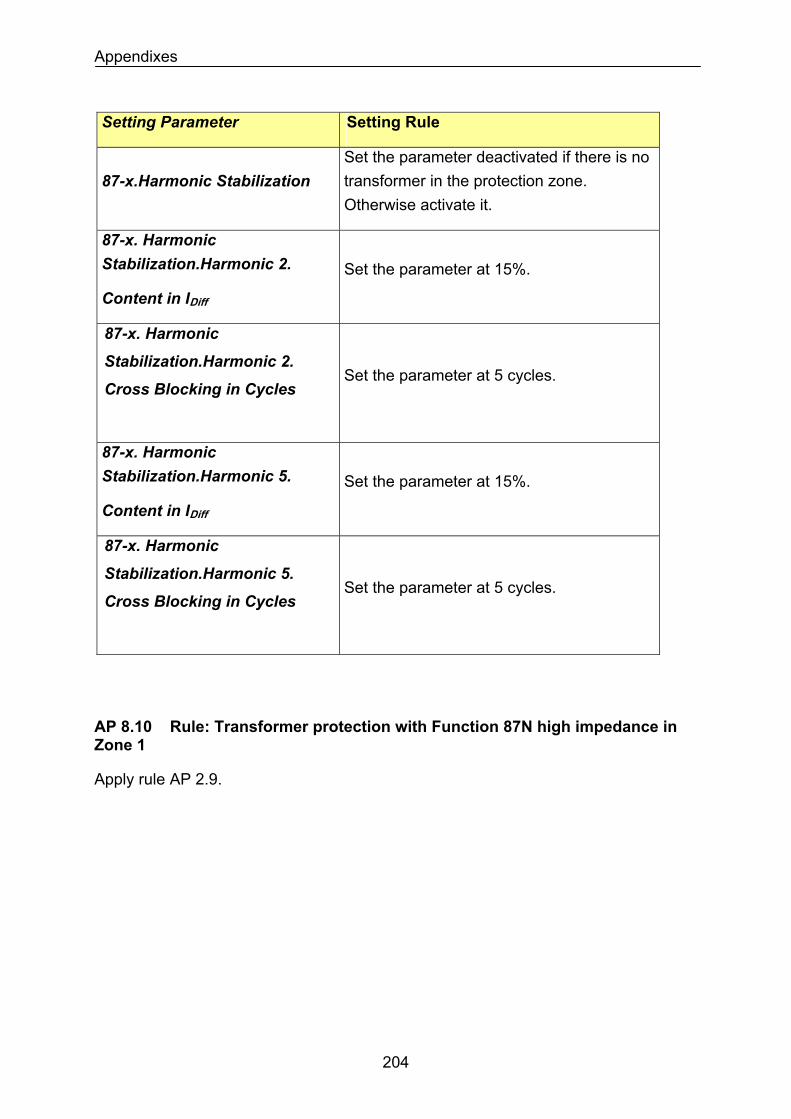
Appendixes
Setting Parameter Setting Rule
87-x.Harmonic Stabilization Set the parameter deactivated if there is no transformer in the protection zone. Otherwise activate it.
87-x. Harmonic Stabilization.Harmonic 2.
Content in IDiff
Set the parameter at 15%.
87-x. Harmonic
Stabilization.Harmonic 2. Set the parameter at 5 cycles.
Cross Blocking in Cycles
87-x. Harmonic Stabilization.Harmonic 5.
Content in IDiff
Set the parameter at 15%.
87-x. Harmonic
Stabilization.Harmonic 5. Set the parameter at 5 cycles.
Cross Blocking in Cycles
AP 8.10 Rule: Transformer protection with Function 87N high impedance in Zone 1
Apply rule AP 2.9.
204
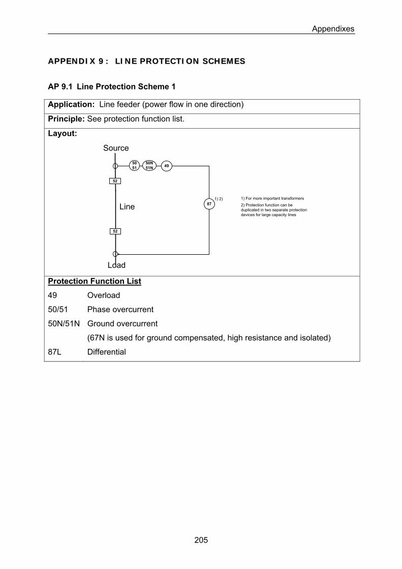
Appendixes
AAPPPPEENNDDIIXX 99 :: LLIINNEE PPRROOTTEECCTTIIOONN SSCCHHEEMMEESS
AP 9.1 Line Protection Scheme 1
Application: Line feeder (power flow in one direction)
Principle: See protection function list.
Layout:
5051
50N51N
52
Source
1) 2) 1) For more important transformers
52
Load
87
49
2) Protection function can be duplicated in two separate protection devices for large capacity lines
Line
Protection Function List
49 Overload
50/51 Phase overcurrent
50N/51N Ground overcurrent
(67N is used for ground compensated, high resistance and isolated)
87L Differential
205
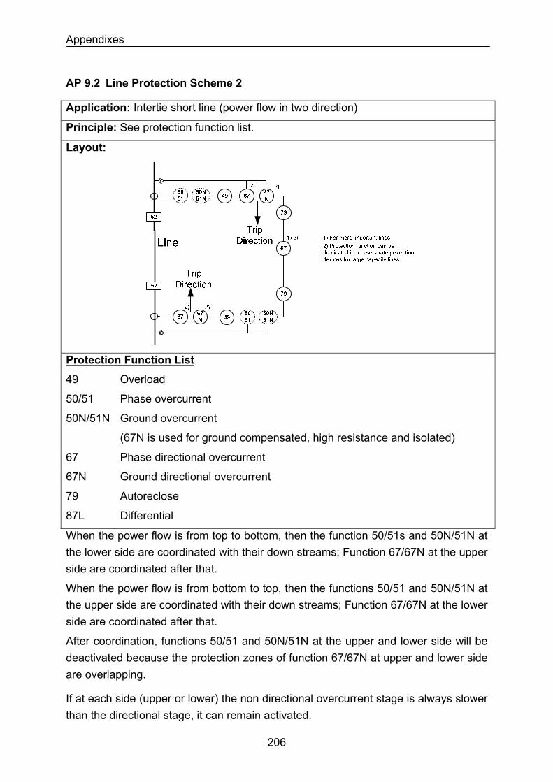
Appendixes
AP 9.2 Line Protection Scheme 2
Application: Intertie short line (power flow in two direction)
Principle: See protection function list.
Layout:
Protection Function List
49 Overload
50/51 Phase overcurrent
50N/51N Ground overcurrent
(67N is used for ground compensated, high resistance and isolated)
67 Phase directional overcurrent
67N Ground directional overcurrent
79 Autoreclose
87L Differential
When the power flow is from top to bottom, then the function 50/51s and 50N/51N at the lower side are coordinated with their down streams; Function 67/67N at the upper side are coordinated after that.
When the power flow is from bottom to top, then the functions 50/51 and 50N/51N at the upper side are coordinated with their down streams; Function 67/67N at the lower side are coordinated after that.
After coordination, functions 50/51 and 50N/51N at the upper and lower side will be deactivated because the protection zones of function 67/67N at upper and lower side are overlapping.
If at each side (upper or lower) the non directional overcurrent stage is always slower than the directional stage, it can remain activated.
206
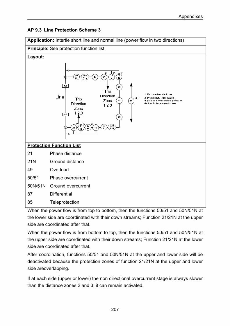
Appendixes
AP 9.3 Line Protection Scheme 3
Application: Intertie short line and normal line (power flow in two directions)
Principle: See protection function list.
Layout:
Protection Function List
21 Phase distance
21N Ground distance
49 Overload
50/51 Phase overcurrent
50N/51N Ground overcurrent
87 Differential
85 Teleprotection
When the power flow is from top to bottom, then the functions 50/51 and 50N/51N at the lower side are coordinated with their down streams; Function 21/21N at the upper side are coordinated after that.
When the power flow is from bottom to top, then the functions 50/51 and 50N/51N at the upper side are coordinated with their down streams; Function 21/21N at the lower side are coordinated after that.
After coordination, functions 50/51 and 50N/51N at the upper and lower side will be deactivated because the protection zones of function 21/21N at the upper and lower side areoverlapping.
If at each side (upper or lower) the non directional overcurrent stage is always slower than the distance zones 2 and 3, it can remain activated.
207
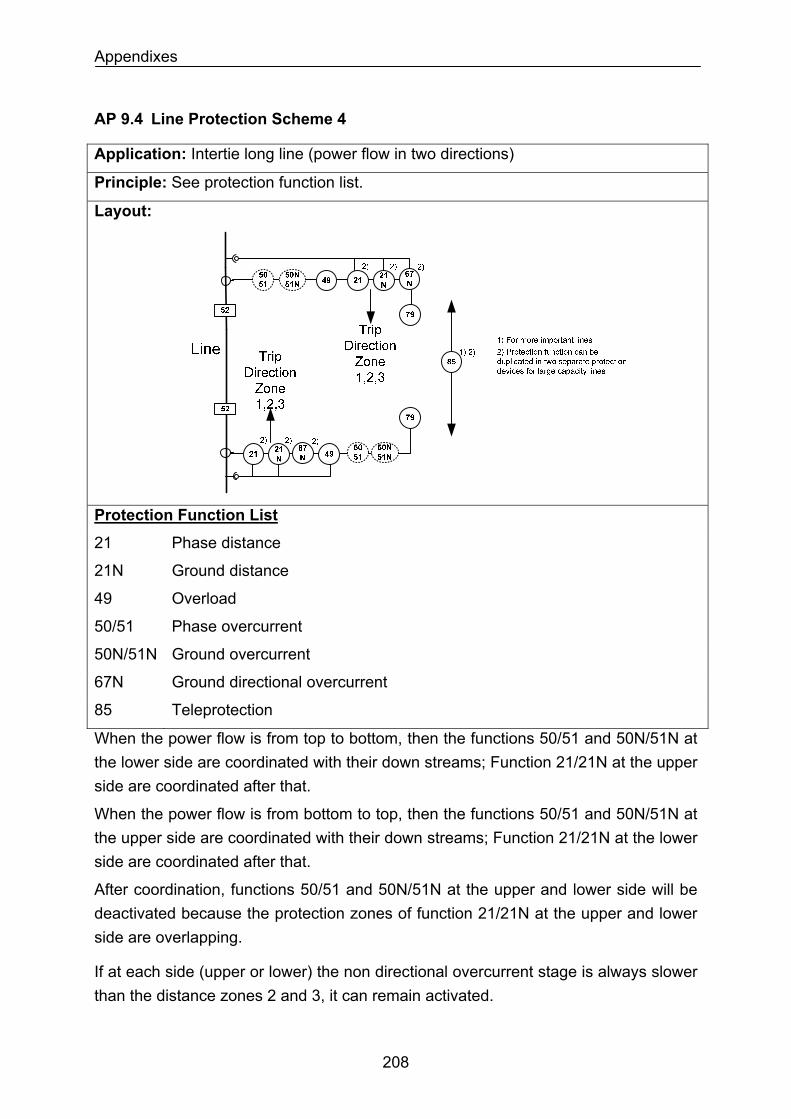
Appendixes
AP 9.4 Line Protection Scheme 4
Application: Intertie long line (power flow in two directions)
Principle: See protection function list.
Layout:
Protection Function List
21 Phase distance
21N Ground distance
49 Overload
50/51 Phase overcurrent
50N/51N Ground overcurrent
67N Ground directional overcurrent
85 Teleprotection
When the power flow is from top to bottom, then the functions 50/51 and 50N/51N at the lower side are coordinated with their down streams; Function 21/21N at the upper side are coordinated after that.
When the power flow is from bottom to top, then the functions 50/51 and 50N/51N at the upper side are coordinated with their down streams; Function 21/21N at the lower side are coordinated after that.
After coordination, functions 50/51 and 50N/51N at the upper and lower side will be deactivated because the protection zones of function 21/21N at the upper and lower side are overlapping.
If at each side (upper or lower) the non directional overcurrent stage is always slower than the distance zones 2 and 3, it can remain activated.
208
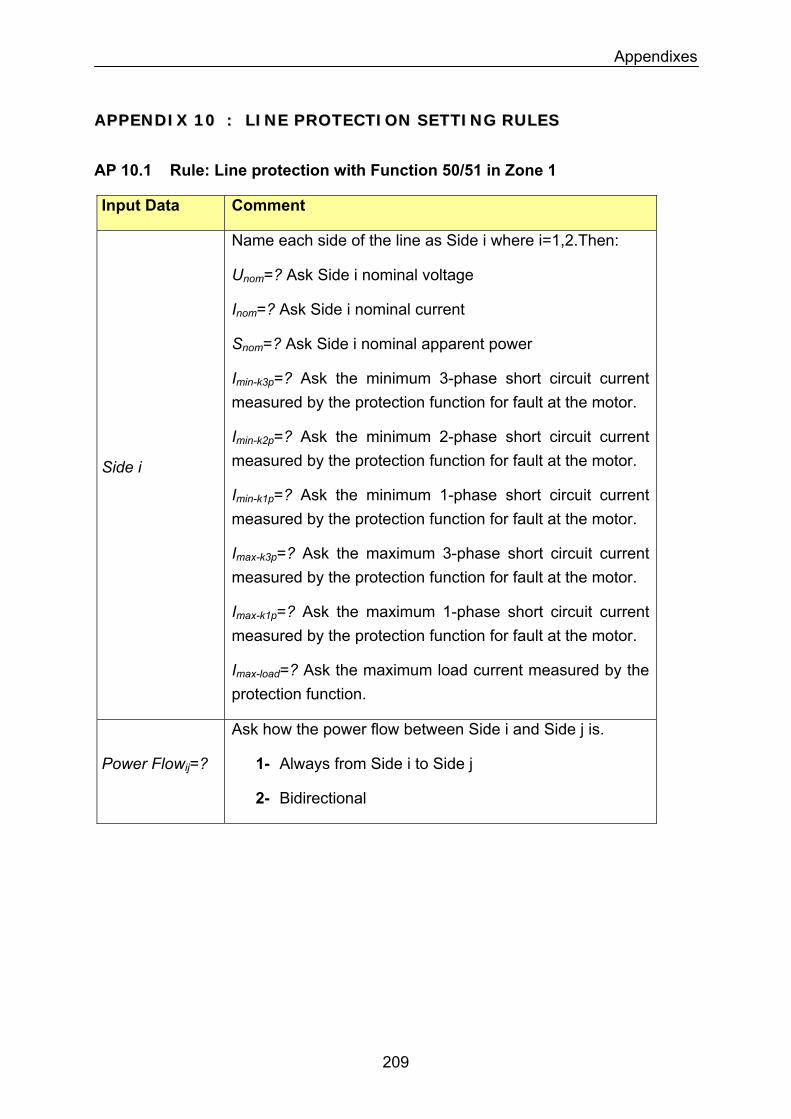
Appendixes
AAPPPPEENNDDIIXX 1100 :: LLIINNEE PPRROOTTEECCTTIIOONN SSEETTTTIINNGG RRUULLEESS
AP 10.1 Rule: Line protection with Function 50/51 in Zone 1
Input Data Comment
Name each side of the line as Side i where i=1,2.Then:
Unom=? Ask Side i nominal voltage
Inom=? Ask Side i nominal current
Snom=? Ask Side i nominal apparent power
Imin-k3p=? Ask the minimum 3-phase short circuit current measured by the protection function for fault at the motor.
Imin-k2p=? Ask the minimum 2-phase short circuit current measured by the protection function for fault at the motor. Side i
Imin-k1p=? Ask the minimum 1-phase short circuit current measured by the protection function for fault at the motor.
Imax-k3p=? Ask the maximum 3-phase short circuit current measured by the protection function for fault at the motor.
Imax-k1p=? Ask the maximum 1-phase short circuit current measured by the protection function for fault at the motor.
Imax-load=? Ask the maximum load current measured by the protection function.
Power Flowij=?
Ask how the power flow between Side i and Side j is.
1- Always from Side i to Side j
2- Bidirectional
209
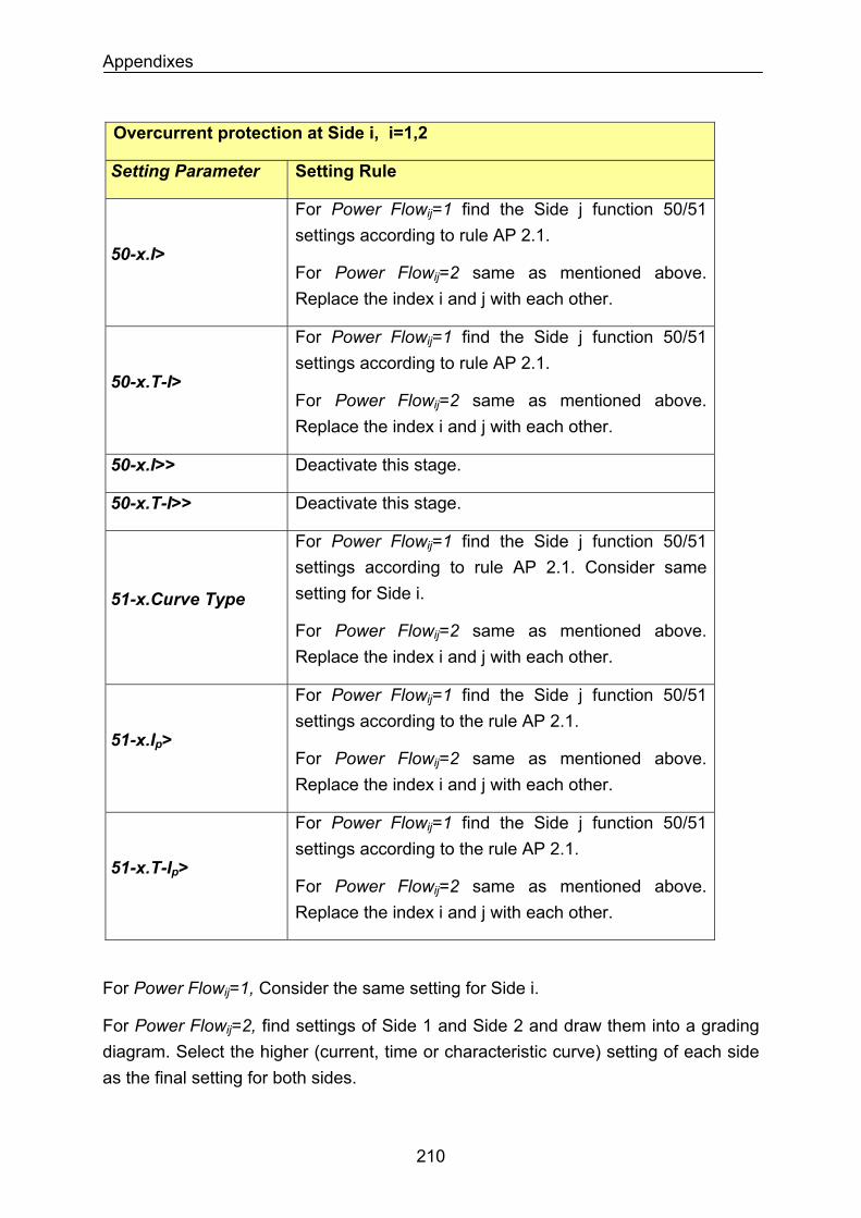
Appendixes
Overcurrent protection at Side i, i=1,2
Setting Parameter Setting Rule
50-x.I>
For Power Flowij=1 find the Side j function 50/51 settings according to rule AP 2.1.
For Power Flowij=2 same as mentioned above. Replace the index i and j with each other.
50-x.T-I>
For Power Flowij=1 find the Side j function 50/51 settings according to rule AP 2.1.
For Power Flowij=2 same as mentioned above. Replace the index i and j with each other.
50-x.I>> Deactivate this stage.
Deactivate this stage. 50-x.T-I>>
For Power Flowij=1 find the Side j function 50/51 settings according to rule AP 2.1. Consider same setting for Side i. 51-x.Curve Type
For Power Flowij=2 same as mentioned above. Replace the index i and j with each other.
51-x.Ip>
For Power Flowij=1 find the Side j function 50/51 settings according to the rule AP 2.1.
For Power Flowij=2 same as mentioned above. Replace the index i and j with each other.
51-x.T-Ip>
For Power Flowij=1 find the Side j function 50/51 settings according to the rule AP 2.1.
For Power Flowij=2 same as mentioned above. Replace the index i and j with each other.
For Power Flowij=1, Consider the same setting for Side i.
For Power Flowij=2, find settings of Side 1 and Side 2 and draw them into a grading diagram. Select the higher (current, time or characteristic curve) setting of each side as the final setting for both sides.
210
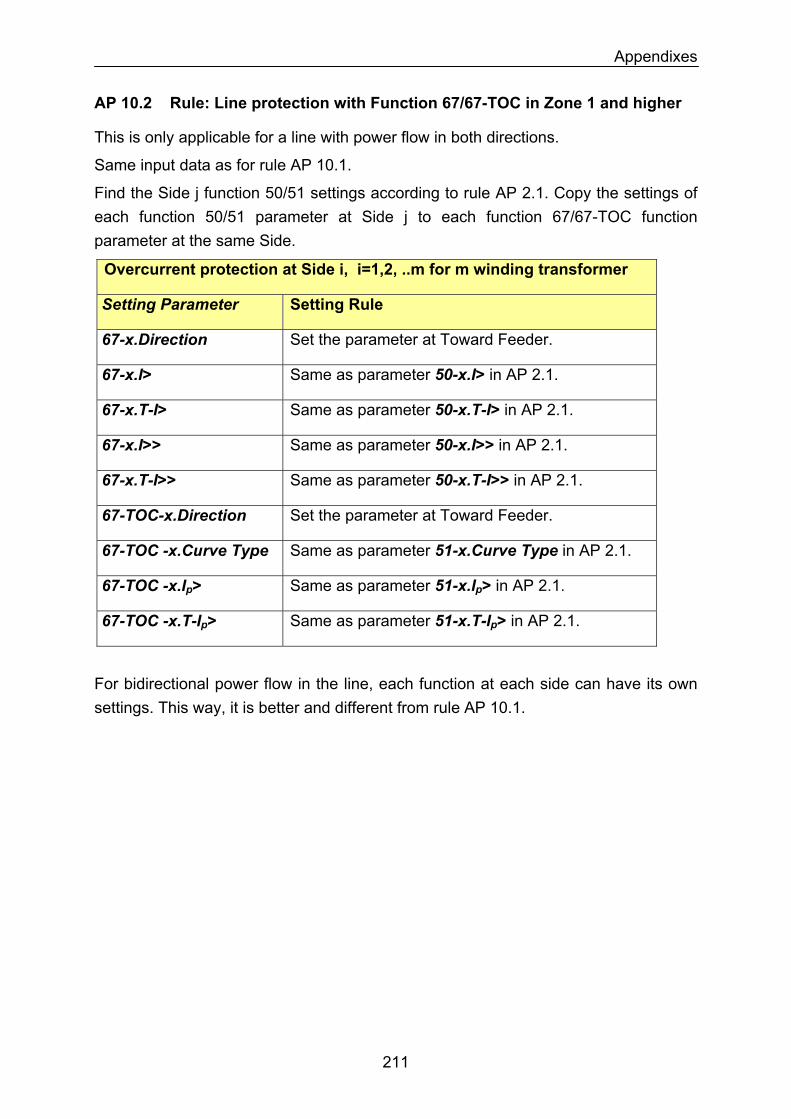
Appendixes
AP 10.2 Rule: Line protection with Function 67/67-TOC in Zone 1 and higher
This is only applicable for a line with power flow in both directions.
Same input data as for rule AP 10.1.
Find the Side j function 50/51 settings according to rule AP 2.1. Copy the settings of each function 50/51 parameter at Side j to each function 67/67-TOC function parameter at the same Side.
Overcurrent protection at Side i, i=1,2, ..m for m winding transformer
Setting Parameter Setting Rule
Set the parameter at Toward Feeder. 67-x.Direction
Same as parameter 50-x.I> in AP 2.1. 67-x.I>
Same as parameter 50-x.T-I> in AP 2.1. 67-x.T-I>
Same as parameter 50-x.I>> in AP 2.1. 67-x.I>>
Same as parameter 50-x.T-I>> in AP 2.1. 67-x.T-I>>
Set the parameter at Toward Feeder. 67-TOC-x.Direction
67-TOC -x.Curve Type Same as parameter 51-x.Curve Type in AP 2.1.
67-TOC -x.Ip> Same as parameter 51-x.Ip> in AP 2.1.
67-TOC -x.T-Ip> Same as parameter 51-x.T-Ip> in AP 2.1.
For bidirectional power flow in the line, each function at each side can have its own settings. This way, it is better and different from rule AP 10.1.
211
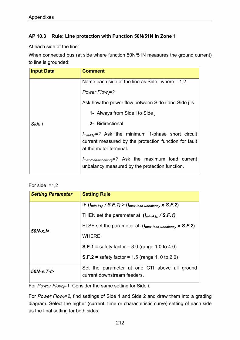
Appendixes
AP 10.3 Rule: Line protection with Function 50N/51N in Zone 1
At each side of the line:
When connected bus (at side where function 50N/51N measures the ground current) to line is grounded:
Input Data Comment
Side i
Name each side of the line as Side i where i=1,2.
Power Flowij=?
Ask how the power flow between Side i and Side j is.
1- Always from Side i to Side j
2- Bidirectional
Imin-k1p=? Ask the minimum 1-phase short circuit current measured by the protection function for fault at the motor terminal.
Imax-load-unbalancy=? Ask the maximum load current unbalancy measured by the protection function.
For side i=1,2
Setting Parameter Setting Rule
IF (Imin-k1p / S.F.1) > (Imax-load-unbalancy x S.F.2)
THEN set the parameter at (Imin-k2p / S.F.1)
ELSE set the parameter at (Imax-load-unbalancy x S.F.2)
WHERE 50N-x.I>
S.F.1 = safety factor = 3.0 (range 1.0 to 4.0)
S.F.2 = safety factor = 1.5 (range 1. 0 to 2.0)
Set the parameter at one CTI above all ground current downstream feeders.
50N-x.T-I>
For Power Flowij=1, Consider the same setting for Side i.
For Power Flowij=2, find settings of Side 1 and Side 2 and draw them into a grading diagram. Select the higher (current, time or characteristic curve) setting of each side as the final setting for both sides.
212
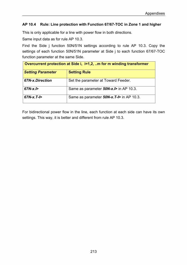
Appendixes
AP 10.4 Rule: Line protection with Function 67/67-TOC in Zone 1 and higher
This is only applicable for a line with power flow in both directions.
Same input data as for rule AP 10.3.
Find the Side j function 50N/51N settings according to rule AP 10.3. Copy the settings of each function 50N/51N parameter at Side j to each function 67/67-TOC function parameter at the same Side.
Overcurrent protection at Side i, i=1,2, ..m for m winding transformer
Setting Parameter Setting Rule
67N-x.Direction Set the parameter at Toward Feeder.
67N-x.I> Same as parameter 50N-x.I> in AP 10.3.
67N-x.T-I> Same as parameter 50N-x.T-I> in AP 10.3.
For bidirectional power flow in the line, each function at each side can have its own settings. This way, it is better and different from rule AP 10.3.
213
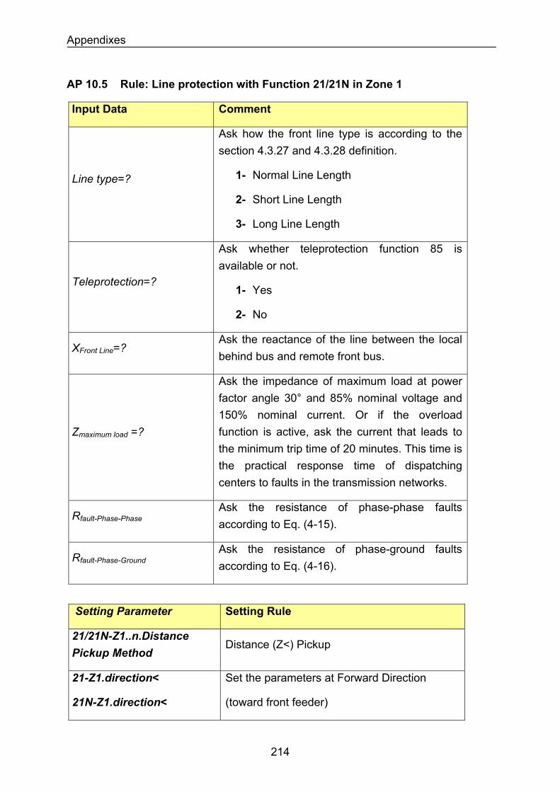
Appendixes
AP 10.5 Rule: Line protection with Function 21/21N in Zone 1
Input Data Comment
Ask how the front line type is according to the section 4.3.27 and 4.3.28 definition.
1- Normal Line Length Line type=?
2- Short Line Length
3- Long Line Length
Ask whether teleprotection function 85 is available or not.
Teleprotection=? 1- Yes
2- No
XFront Line=? Ask the reactance of the line between the local behind bus and remote front bus.
Zmaximum load =?
Ask the impedance of maximum load at power factor angle 30° and 85% nominal voltage and 150% nominal current. Or if the overload function is active, ask the current that leads to the minimum trip time of 20 minutes. This time is the practical response time of dispatching centers to faults in the transmission networks.
Rfault-Phase-PhaseAsk the resistance of phase-phase faults according to Eq. (4-15).
Rfault-Phase-GroundAsk the resistance of phase-ground faults according to Eq. (4-16).
Setting Parameter Setting Rule
21/21N-Z1..n.Distance Pickup Method
Distance (Z<) Pickup
21-Z1.direction<
21N-Z1.direction<
Set the parameters at Forward Direction
(toward front feeder)
214
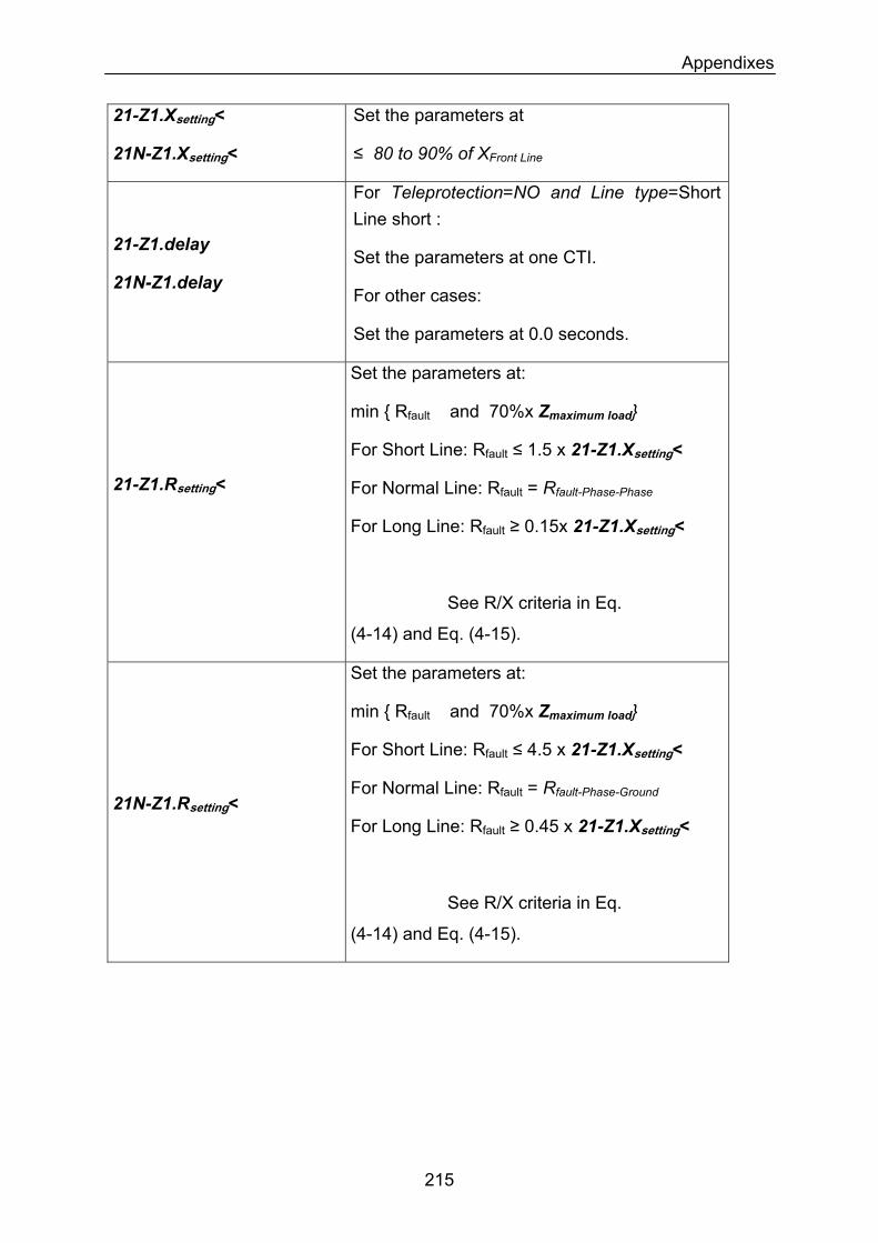
Appendixes
21-Z1.Xsetting<
21N-Z1.Xsetting<
Set the parameters at
≤ 80 to 90% of XFront Line
21-Z1.delay
21N-Z1.delay
For Teleprotection=NO and Line type=Short Line short :
Set the parameters at one CTI.
For other cases:
Set the parameters at 0.0 seconds.
21-Z1.Rsetting<
Set the parameters at:
min Rfault and 70%x Zmaximum load
For Short Line: Rfault ≤ 1.5 x 21-Z1.Xsetting<
For Normal Line: Rfault = Rfault-Phase-Phase
For Long Line: Rfault ≥ 0.15x 21-Z1.Xsetting<
See R/X criteria in Eq.
(4-14) and Eq. (4-15).
21N-Z1.Rsetting<
Set the parameters at:
min Rfault and 70%x Zmaximum load
For Short Line: Rfault ≤ 4.5 x 21-Z1.Xsetting<
For Normal Line: Rfault = Rfault-Phase-Ground
For Long Line: Rfault ≥ 0.45 x 21-Z1.Xsetting<
See R/X criteria in Eq.
(4-14) and Eq. (4-15).
215
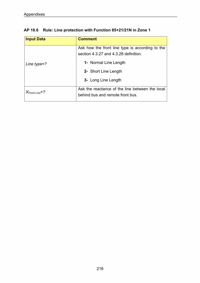
Appendixes
AP 10.6 Rule: Line protection with Function 85+21/21N in Zone 1
Input Data Comment
Line type=?
Ask how the front line type is according to the section 4.3.27 and 4.3.28 definition.
1- Normal Line Length
2- Short Line Length
3- Long Line Length
XFront Line=? Ask the reactance of the line between the local behind bus and remote front bus.
216
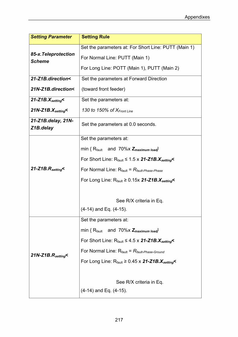
Appendixes
Setting Parameter Setting Rule
85-x.Teleprotection Scheme
Set the parameters at: For Short Line: PUTT (Main 1)
For Normal Line: PUTT (Main 1)
For Long Line: POTT (Main 1), PUTT (Main 2)
21-Z1B.direction<
21N-Z1B.direction<
Set the parameters at Forward Direction
(toward front feeder)
21-Z1B.Xsetting<
21N-Z1B.Xsetting<
Set the parameters at:
130 to 150% of XFront Line
21-Z1B.delay, 21N-Z1B.delay
Set the parameters at 0.0 seconds.
Set the parameters at:
min Rfault and 70%x Zmaximum load
For Short Line: Rfault ≤ 1.5 x 21-Z1B.Xsetting<
21-Z1B.Rsetting< For Normal Line: Rfault = Rfault-Phase-Phase
For Long Line: Rfault ≥ 0.15x 21-Z1B.Xsetting<
See R/X criteria in Eq.
(4-14) and Eq. (4-15).
Set the parameters at:
min Rfault and 70%x Zmaximum load
For Short Line: Rfault ≤ 4.5 x 21-Z1B.Xsetting<
For Normal Line: Rfault = Rfault-Phase-Ground
For Long Line: Rfault ≥ 0.45 x 21-Z1B.Xsetting<
21N-Z1B.Rsetting<
See R/X criteria in Eq.
(4-14) and Eq. (4-15).
217
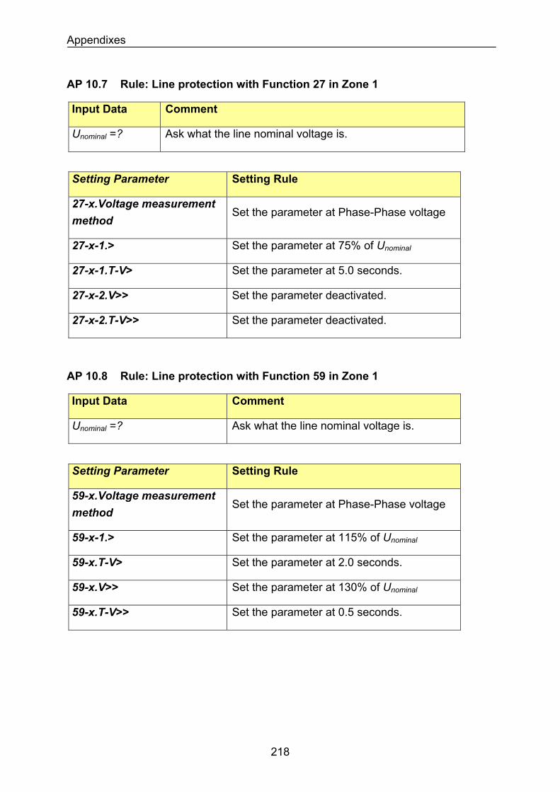
Appendixes
AP 10.7 Rule: Line protection with Function 27 in Zone 1
Input Data Comment
Ask what the line nominal voltage is. Unominal =?
Setting Parameter Setting Rule
27-x.Voltage measurement method
Set the parameter at Phase-Phase voltage
Set the parameter at 75% of Unominal27-x-1.>
Set the parameter at 5.0 seconds. 27-x-1.T-V>
Set the parameter deactivated. 27-x-2.V>>
Set the parameter deactivated. 27-x-2.T-V>>
AP 10.8 Rule: Line protection with Function 59 in Zone 1
Input Data Comment
Ask what the line nominal voltage is. Unominal =?
Setting Parameter Setting Rule
59-x.Voltage measurement method
Set the parameter at Phase-Phase voltage
59-x-1.> Set the parameter at 115% of Unominal
59-x.T-V> Set the parameter at 2.0 seconds.
59-x.V>> Set the parameter at 130% of Unominal
59-x.T-V>> Set the parameter at 0.5 seconds.
218
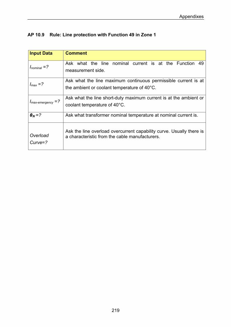
Appendixes
AP 10.9 Rule: Line protection with Function 49 in Zone 1
Input Data Comment
Inominal =? Ask what the line nominal current is at the Function 49 measurement side.
Imax =? Ask what the line maximum continuous permissible current is at the ambient or coolant temperature of 40°C.
Imax-emergency =? Ask what the line short-duty maximum current is at the ambient or coolant temperature of 40°C.
θN =? Ask what transformer nominal temperature at nominal current is.
Overload Curve=?
Ask the line overload overcurrent capability curve. Usually there is a characteristic from the cable manufacturers.
219
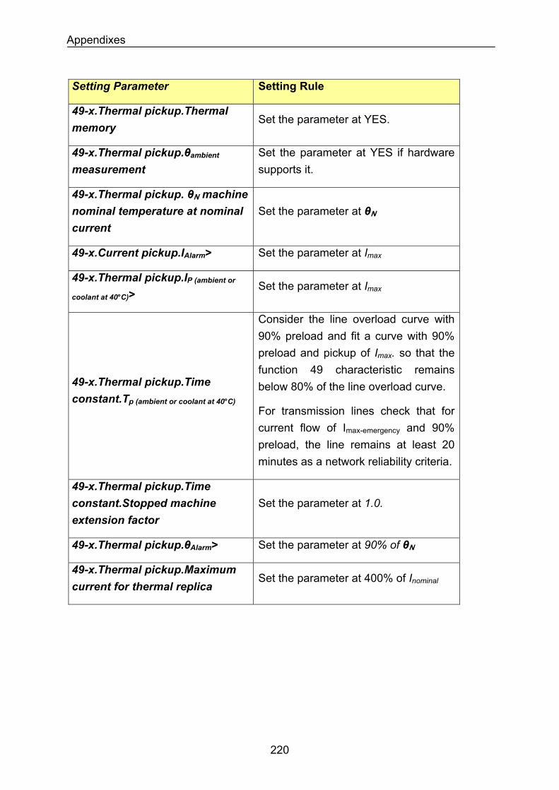
Appendixes
Setting Parameter Setting Rule
49-x.Thermal pickup.Thermal memory
Set the parameter at YES.
Set the parameter at YES if hardware supports it.
49-x.Thermal pickup.θambient measurement
49-x.Thermal pickup. θN machine nominal temperature at nominal current
Set the parameter at θN
Set the parameter at Imax49-x.Current pickup.IAlarm>
49-x.Thermal pickup.IP (ambient or
coolant at 40°C)> Set the parameter at Imax
Consider the line overload curve with 90% preload and fit a curve with 90% preload and pickup of Imax. so that the function 49 characteristic remains below 80% of the line overload curve. 49-x.Thermal pickup.Time
constant.Tp (ambient or coolant at 40°C)For transmission lines check that for current flow of Imax-emergency and 90% preload, the line remains at least 20 minutes as a network reliability criteria.
49-x.Thermal pickup.Time constant.Stopped machine extension factor
Set the parameter at 1.0.
49-x.Thermal pickup.θAlarm> Set the parameter at 90% of θN
49-x.Thermal pickup.Maximum current for thermal replica
Set the parameter at 400% of Inominal
220
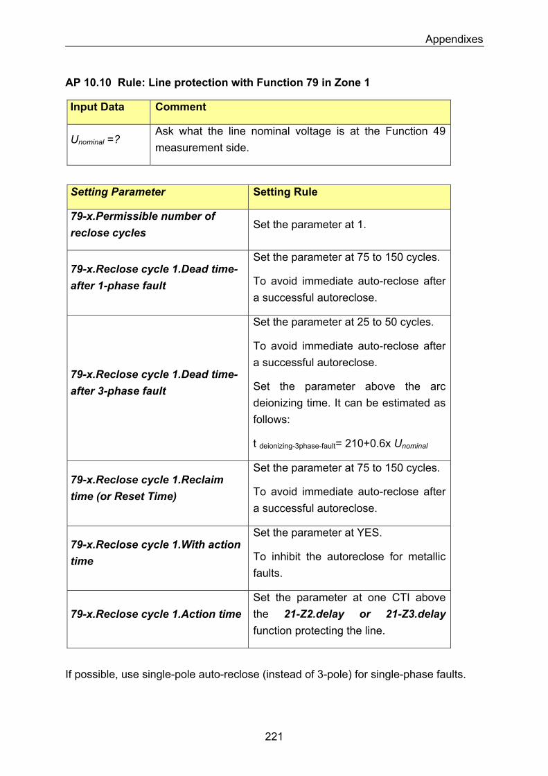
Appendixes
AP 10.10 Rule: Line protection with Function 79 in Zone 1
Input Data Comment
Unominal =? Ask what the line nominal voltage is at the Function 49 measurement side.
Setting Parameter Setting Rule
79-x.Permissible number of reclose cycles
Set the parameter at 1.
Set the parameter at 75 to 150 cycles. 79-x.Reclose cycle 1.Dead time-after 1-phase fault To avoid immediate auto-reclose after
a successful autoreclose.
Set the parameter at 25 to 50 cycles.
To avoid immediate auto-reclose after a successful autoreclose.
79-x.Reclose cycle 1.Dead time-after 3-phase fault Set the parameter above the arc
deionizing time. It can be estimated as follows:
t deionizing-3phase-fault= 210+0.6x Unominal
Set the parameter at 75 to 150 cycles. 79-x.Reclose cycle 1.Reclaim time (or Reset Time) To avoid immediate auto-reclose after
a successful autoreclose.
79-x.Reclose cycle 1.With action time
Set the parameter at YES.
To inhibit the autoreclose for metallic faults.
79-x.Reclose cycle 1.Action time Set the parameter at one CTI above the 21-Z2.delay or 21-Z3.delay function protecting the line.
If possible, use single-pole auto-reclose (instead of 3-pole) for single-phase faults.
221
Appendixes
For overhead lines with shunt reactor, when single pole autoreclosing is intended on the planned transmission line, two phenomena must be considered with respect to the shunt reactor:
a. Overvoltages: During one-side opening conditions the overvoltages based on Ferranti effect will be reduced when using the shunt reactor. However, during dead-time the of single-pole autoreclosing cycle, the presence of the shunt reactor can dangerously increase the fundamental frequency voltage onto the de-energized line conductors. This voltage is induced onto the de-energized line from the energized conductors of the same circuit or another circuit on the same right of way due to the parallel resonance between zero-sequence reactance of the shunt reactor and the line capacitance. This effect of fundamental frequency overvoltages during dead time single-pole auto-reclosure can be threatening to the switchgear and must be therefore analyzed.
b. Secondary arc extinction: The second phenomenon that must be considered is connected with the secondary arc current. After a single phase fault is detected and the faulted phase is isolated (during dead-time), the arc is still fed by the healthy phases that remain energized. Thereby, both capacitive and inductive coupling exist. Knowing the line parameters and by neglecting the fault impedance the value of the coupled current (secondary arc current) can be calculated. Using this information the minimum dead-time of the single pole autoreclosing can be estimated, since there exists a lot of field and laboratory tests on this subject that have been performed to find this dependency.
The detailed description of the above mentioned phenomena can be found in [47], [48], [49].
222
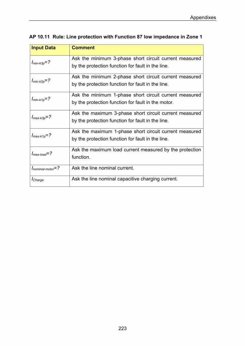
Appendixes
AP 10.11 Rule: Line protection with Function 87 low impedance in Zone 1
Input Data Comment
Ask the minimum 3-phase short circuit current measured by the protection function for fault in the line.
Imin-k3p=?
Ask the minimum 2-phase short circuit current measured by the protection function for fault in the line.
Imin-k2p=?
Imin-k1p=? Ask the minimum 1-phase short circuit current measured by the protection function for fault in the motor.
Imax-k3p=? Ask the maximum 3-phase short circuit current measured by the protection function for fault in the line.
Imax-k1p=? Ask the maximum 1-phase short circuit current measured by the protection function for fault in the line.
Imax-load=? Ask the maximum load current measured by the protection function.
Inominal-motor=? Ask the line nominal current.
Ask the line nominal capacitive charging current. ICharge
223
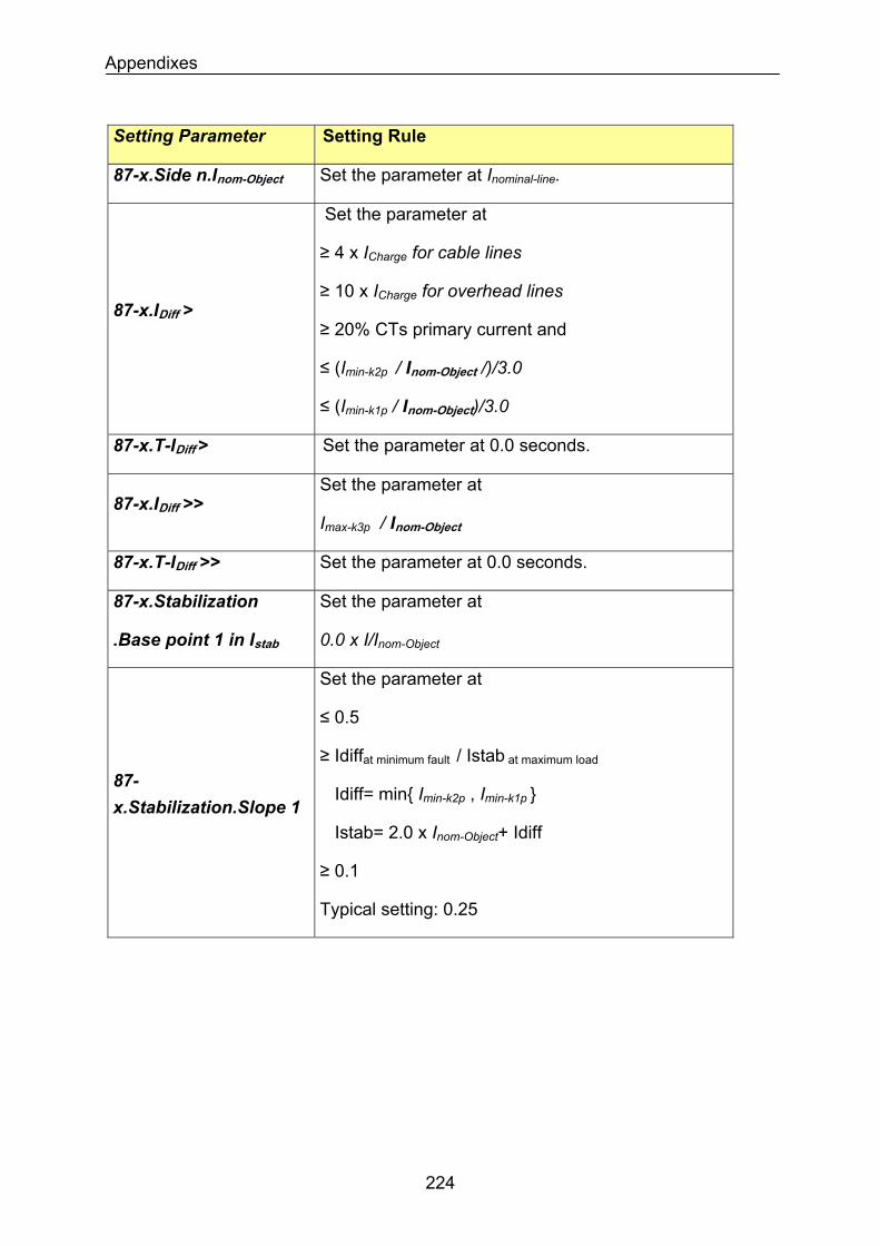
Appendixes
Setting Parameter Setting Rule
87-x.Side n.Inom-Object Set the parameter at Inominal-line.
87-x.IDiff >
Set the parameter at
≥ 4 x ICharge for cable lines
≥ 10 x ICharge for overhead lines
≥ 20% CTs primary current and
≤ (Imin-k2p / Inom-Object /)/3.0
≤ (Imin-k1p / Inom-Object)/3.0
87-x.T-IDiff > Set the parameter at 0.0 seconds.
Set the parameter at 87-x.IDiff >>
Imax-k3p / Inom-Object
87-x.T-IDiff >> Set the parameter at 0.0 seconds.
87-x.Stabilization
.Base point 1 in Istab
Set the parameter at
0.0 x I/Inom-Object
87-x.Stabilization.Slope 1
Set the parameter at
≤ 0.5
≥ Idiffat minimum fault / Istab at maximum load
Idiff= min Imin-k2p , Imin-k1p
Istab= 2.0 x Inom-Object+ Idiff
≥ 0.1
Typical setting: 0.25
224
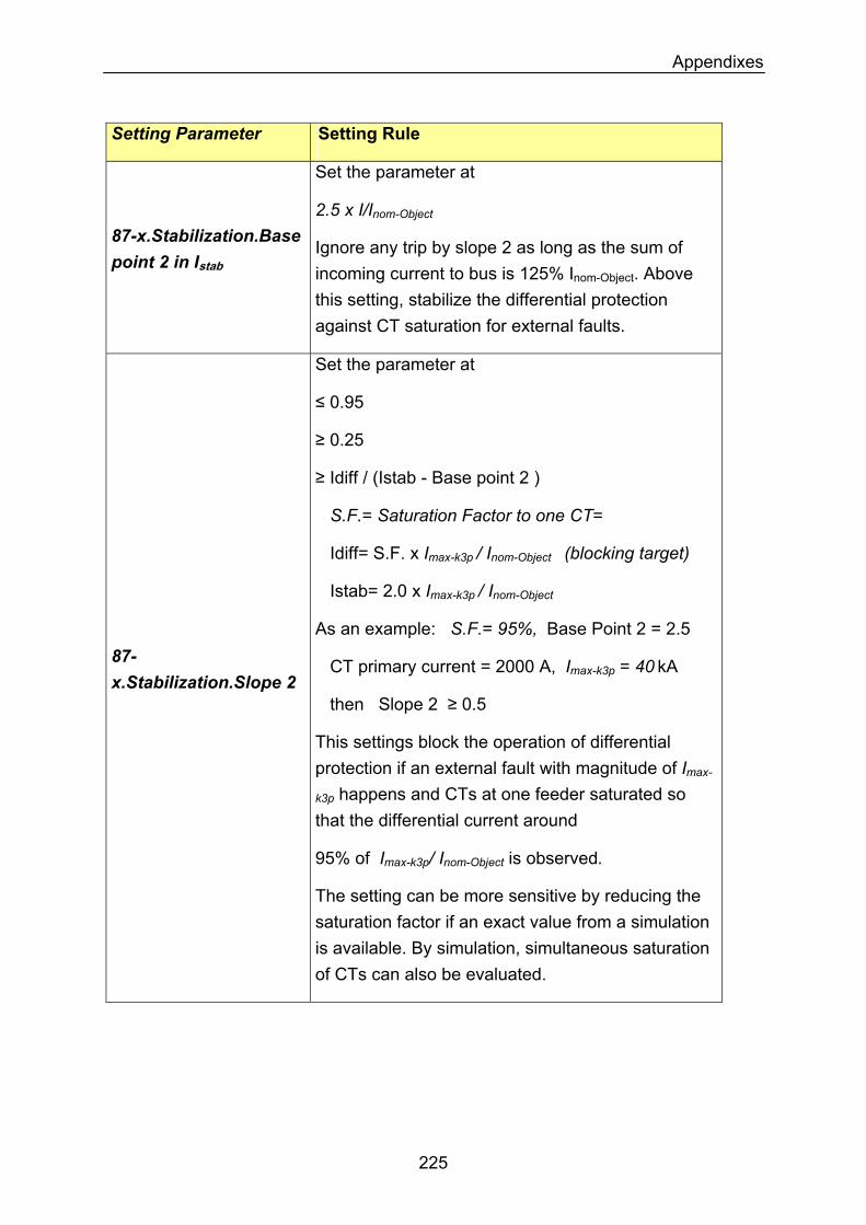
Appendixes
Setting Parameter Setting Rule
Set the parameter at
2.5 x I/Inom-Object
87-x.Stabilization.Base point 2 in Istab
Ignore any trip by slope 2 as long as the sum of incoming current to bus is 125% Inom-Object. Above this setting, stabilize the differential protection against CT saturation for external faults.
87-x.Stabilization.Slope 2
Set the parameter at
≤ 0.95
≥ 0.25
≥ Idiff / (Istab - Base point 2 )
S.F.= Saturation Factor to one CT=
Idiff= S.F. x Imax-k3p / Inom-Object (blocking target)
Istab= 2.0 x Imax-k3p / Inom-Object
As an example: S.F.= 95%, Base Point 2 = 2.5
CT primary current = 2000 A, Imax-k3p = 40 kA
then Slope 2 ≥ 0.5
This settings block the operation of differential protection if an external fault with magnitude of Imax-
k3p happens and CTs at one feeder saturated so that the differential current around
95% of Imax-k3p/ Inom-Object is observed.
The setting can be more sensitive by reducing the saturation factor if an exact value from a simulation is available. By simulation, simultaneous saturation of CTs can also be evaluated.
225

Appendixes
Setting Parameter Setting Rule
87-x.ADD-ON Stabilization
Set the parameter Enabled.
This feature blocks the function against far external short-circuits with relatively low magnitude but with large time constant (for example near generators)
87-x.ADD-ON Stabilization.Left boarder.Pickup in Istab
Set the parameter at 4.0 x Inom-Object
This setting detects far external faults above 2.0 x Inom-Object that lead to CT saturation mainly because of the short-circuit DC component. It accordingly blocks the operation differential protection.
As an example consider a generator, a bus with diff. protection and a step-up transformer with a 3-phase fault at HV side.
87-x.ADD-ON Stabilization.Top boarder.Work with Slope
Set the parameter at Slope 1
87-x.ADD-ON Stabilization.Duration in Cycles
Set the parameter at 15 cycles
By simulation of CT saturation due to short-circuit DC component and finding the time needed for differential protection to detect an Idiff-Istab point in trip area; this parameter can be set more precisely.
226
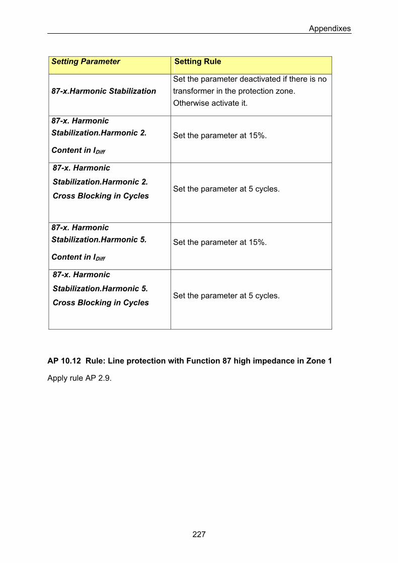
Appendixes
Setting Parameter Setting Rule
87-x.Harmonic Stabilization Set the parameter deactivated if there is no transformer in the protection zone. Otherwise activate it.
87-x. Harmonic Stabilization.Harmonic 2. Set the parameter at 15%.
Content in IDiff
87-x. Harmonic
Stabilization.Harmonic 2. Set the parameter at 5 cycles.
Cross Blocking in Cycles
87-x. Harmonic Stabilization.Harmonic 5. Set the parameter at 15%.
Content in IDiff
87-x. Harmonic
Stabilization.Harmonic 5. Set the parameter at 5 cycles.
Cross Blocking in Cycles
AP 10.12 Rule: Line protection with Function 87 high impedance in Zone 1
Apply rule AP 2.9.
227
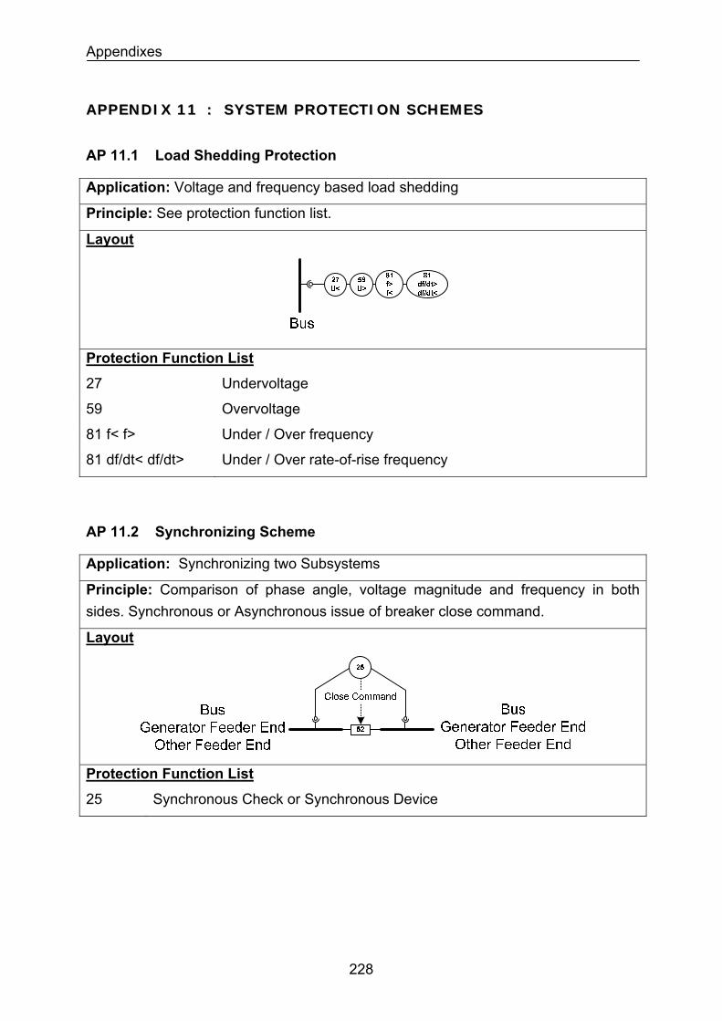
Appendixes
AAPPPPEENNDDIIXX 1111 :: SSYYSSTTEEMM PPRROOTTEECCTTIIOONN SSCCHHEEMMEESS
AP 11.1 Load Shedding Protection
Application: Voltage and frequency based load shedding
Principle: See protection function list.
Layout
Protection Function List
27 Undervoltage
59 Overvoltage
81 f< f> Under / Over frequency
81 df/dt< df/dt> Under / Over rate-of-rise frequency
AP 11.2 Synchronizing Scheme
Application: Synchronizing two Subsystems
Principle: Comparison of phase angle, voltage magnitude and frequency in both sides. Synchronous or Asynchronous issue of breaker close command.
Layout
Protection Function List
25 Synchronous Check or Synchronous Device
228
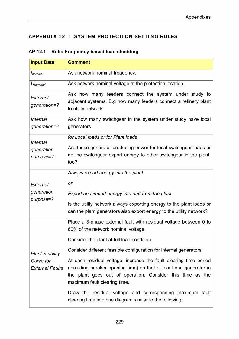
Appendixes
AAPPPPEENNDDIIXX 1122 :: SSYYSSTTEEMM PPRROOTTEECCTTIIOONN SSEETTTTIINNGG RRUULLEESS
AP 12.1 Rule: Frequency based load shedding
Input Data Comment
fnominal Ask network nominal frequency.
Unominal Ask network nominal voltage at the protection location.
External generation=?
Ask how many feeders connect the system under study to adjacent systems. E.g how many feeders connect a refinery plant to utility network.
Ask how many switchgear in the system under study have local generators.
Internal generation=?
Internal generation purpose=?
for Local loads or for Plant loads
Are these generator producing power for local switchgear loads or do the switchgear export energy to other switchgear in the plant, too?
External generation purpose=?
Always export energy into the plant
or
Export and import energy into and from the plant
Is the utility network always exporting energy to the plant loads or can the plant generators also export energy to the utility network?
Place a 3-phase external fault with residual voltage between 0 to 80% of the network nominal voltage.
Consider the plant at full load condition.
Consider different feasible configuration for internal generators.
At each residual voltage, increase the fault clearing time period (including breaker opening time) so that at least one generator in the plant goes out of operation. Consider this time as the maximum fault clearing time.
Plant Stability Curve for External Faults
Draw the residual voltage and corresponding maximum fault clearing time into one diagram similar to the following:
229
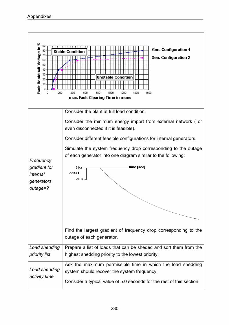
Appendixes
Frequency gradient for internal generators outage=?
Consider the plant at full load condition.
Consider the minimum energy import from external network ( or even disconnected if it is feasible).
Consider different feasible configurations for internal generators.
Simulate the system frequency drop corresponding to the outage of each generator into one diagram similar to the following:
Find the largest gradient of frequency drop corresponding to the outage of each generator.
Load shedding priority list
Prepare a list of loads that can be sheded and sort them from the highest shedding priority to the lowest priority.
Load shedding activity time
Ask the maximum permissible time in which the load shedding system should recover the system frequency.
Consider a typical value of 5.0 seconds for the rest of this section.
230
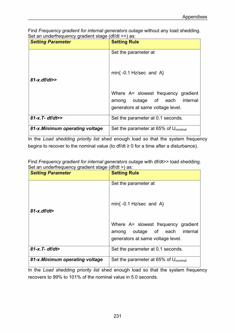
Appendixes
Find Frequency gradient for internal generators outage without any load shedding. Set an underfrequency gradient stage (df/dt >>) as: Setting Parameter Setting Rule
81-x.df/dt>>
Set the parameter at
min -0.1 Hz/sec and A
Where A= slowest frequency gradient among outage of each internal generators at same voltage level.
81-x.T- df/dt>> Set the parameter at 0.1 seconds.
81-x.Minimum operating voltage Set the parameter at 65% of Unominal
In the Load shedding priority list shed enough load so that the system frequency begins to recover to the nominal value (to df/dt ≥ 0 for a time after a disturbance).
Find Frequency gradient for internal generators outage with df/dt>> load shedding. Set an underfrequency gradient stage (df/dt >) as: Setting Parameter Setting Rule
Set the parameter at
min -0.1 Hz/sec and A 81-x.df/dt>
Where A= slowest frequency gradient among outage of each internal generators at same voltage level.
Set the parameter at 0.1 seconds. 81-x.T- df/dt>
Set the parameter at 65% of Unominal81-x.Minimum operating voltage
In the Load shedding priority list shed enough load so that the system frequency recovers to 99% to 101% of the nominal value in 5.0 seconds.
231
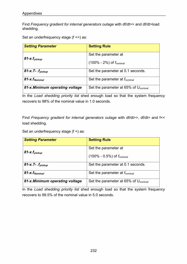
Appendixes
Find Frequency gradient for internal generators outage with df/dt>> and df/dt>load shedding. Set an underfrequency stage (f <<) as: Setting Parameter Setting Rule
81-x.fpickupSet the parameter at
(100% - 2%) of fnominal
81-x.T- .fpickup Set the parameter at 0.1 seconds.
81-x.fNominal Set the parameter at fnominal
81-x.Minimum operating voltage Set the parameter at 65% of Unominal
In the Load shedding priority list shed enough load so that the system frequency recovers to 98% of the nominal value in 1.0 seconds.
Find Frequency gradient for internal generators outage with df/dt>>, df/dt> and f<< load shedding.
Set an underfrequency stage (f <) as:
Setting Parameter Setting Rule
Set the parameter at 81-x.fpickup
(100% - 0.5%) of fnominal
Set the parameter at 0.1 seconds. 81-x.T- .fpickup
Set the parameter at fnominal81-x.fNominal
81-x.Minimum operating voltage Set the parameter at 65% of Unominal
In the Load shedding priority list shed enough load so that the system frequency recovers to 99.5% of the nominal value in 5.0 seconds.
232
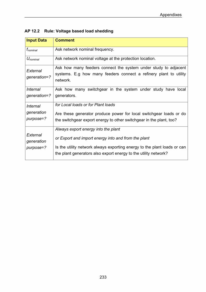
Appendixes
AP 12.2 Rule: Voltage based load shedding
Input Data Comment
Ask network nominal frequency. fnominal
Ask network nominal voltage at the protection location. Unominal
External generation=?
Ask how many feeders connect the system under study to adjacent systems. E.g how many feeders connect a refinery plant to utility network.
Internal generation=?
Ask how many switchgear in the system under study have local generators.
Internal generation purpose=?
for Local loads or for Plant loads
Are these generator produce power for local switchgear loads or do the switchgear export energy to other switchgear in the plant, too?
External generation purpose=?
Always export energy into the plant
or Export and import energy into and from the plant
Is the utility network always exporting energy to the plant loads or can the plant generators also export energy to the utility network?
233
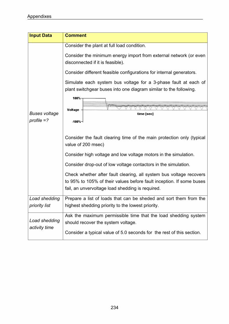
Appendixes
Input Data Comment
Consider the plant at full load condition.
Consider the minimum energy import from external network (or even disconnected if it is feasible).
Consider different feasible configurations for internal generators.
Simulate each system bus voltage for a 3-phase fault at each of plant switchgear buses into one diagram similar to the following.
Buses voltage profile =?
Consider the fault clearing time of the main protection only (typical value of 200 msec)
Consider high voltage and low voltage motors in the simulation.
Consider drop-out of low voltage contactors in the simulation.
Check whether after fault clearing, all system bus voltage recovers to 95% to 105% of their values before fault inception. If some buses fail, an unvervoltage load shedding is required.
Load shedding priority list
Prepare a list of loads that can be sheded and sort them from the highest shedding priority to the lowest priority.
Ask the maximum permissible time that the load shedding system should recover the system voltage. Load shedding
activity time Consider a typical value of 5.0 seconds for the rest of this section.
234
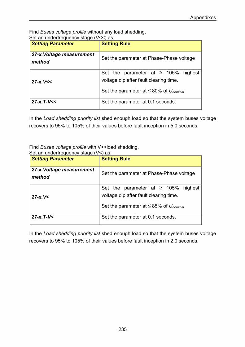
Appendixes
Find Buses voltage profile without any load shedding. Set an underfrequency stage (V<<) as: Setting Parameter Setting Rule
27-x.Voltage measurement method
Set the parameter at Phase-Phase voltage
27-x.V<<
Set the parameter at ≥ 105% highest voltage dip after fault clearing time.
Set the parameter at ≤ 80% of Unominal
Set the parameter at 0.1 seconds. 27-x.T-V<<
In the Load shedding priority list shed enough load so that the system buses voltage recovers to 95% to 105% of their values before fault inception in 5.0 seconds.
Find Buses voltage profile with V<<load shedding. Set an underfrequency stage (V<) as: Setting Parameter Setting Rule
27-x.Voltage measurement method
Set the parameter at Phase-Phase voltage
27-x.V<
Set the parameter at ≥ 105% highest voltage dip after fault clearing time.
Set the parameter at ≤ 85% of Unominal
27-x.T-V< Set the parameter at 0.1 seconds.
In the Load shedding priority list shed enough load so that the system buses voltage recovers to 95% to 105% of their values before fault inception in 2.0 seconds.
235
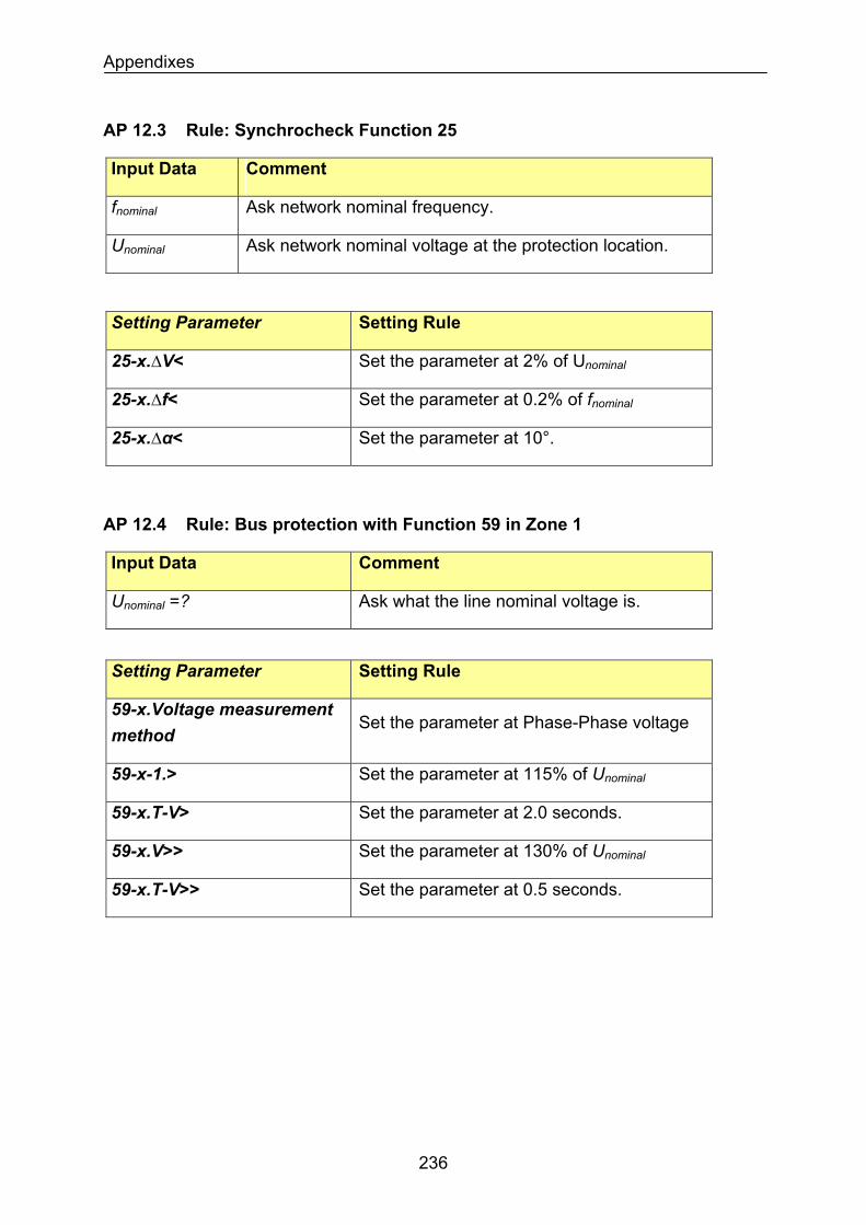
Appendixes
AP 12.3 Rule: Synchrocheck Function 25
Input Data Comment
Ask network nominal frequency. fnominal
Ask network nominal voltage at the protection location. Unominal
Setting Parameter Setting Rule
Set the parameter at 2% of Unominal25-x.∆V<
Set the parameter at 0.2% of fnominal25-x.∆f<
Set the parameter at 10°. 25-x.∆α<
AP 12.4 Rule: Bus protection with Function 59 in Zone 1
Input Data Comment
Ask what the line nominal voltage is. Unominal =?
Setting Parameter Setting Rule
59-x.Voltage measurement method
Set the parameter at Phase-Phase voltage
Set the parameter at 115% of Unominal59-x-1.>
Set the parameter at 2.0 seconds. 59-x.T-V>
Set the parameter at 130% of Unominal59-x.V>>
Set the parameter at 0.5 seconds. 59-x.T-V>>
236
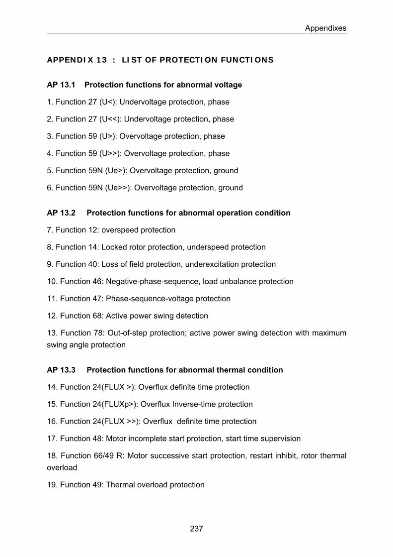
Appendixes
AAPPPPEENNDDIIXX 1133 :: LLIISSTT OOFF PPRROOTTEECCTTIIOONN FFUUNNCCTTIIOONNSS
AP 13.1 Protection functions for abnormal voltage
1. Function 27 (U<): Undervoltage protection, phase
2. Function 27 (U<<): Undervoltage protection, phase
3. Function 59 (U>): Overvoltage protection, phase
4. Function 59 (U>>): Overvoltage protection, phase
5. Function 59N (Ue>): Overvoltage protection, ground
6. Function 59N (Ue>>): Overvoltage protection, ground
AP 13.2 Protection functions for abnormal operation condition
7. Function 12: overspeed protection
8. Function 14: Locked rotor protection, underspeed protection
9. Function 40: Loss of field protection, underexcitation protection
10. Function 46: Negative-phase-sequence, load unbalance protection
11. Function 47: Phase-sequence-voltage protection
12. Function 68: Active power swing detection
13. Function 78: Out-of-step protection; active power swing detection with maximum swing angle protection
AP 13.3 Protection functions for abnormal thermal condition
14. Function 24(FLUX >): Overflux definite time protection
15. Function 24(FLUXp>): Overflux Inverse-time protection
16. Function 24(FLUX >>): Overflux definite time protection
17. Function 48: Motor incomplete start protection, start time supervision
18. Function 66/49 R: Motor successive start protection, restart inhibit, rotor thermal overload
19. Function 49: Thermal overload protection
237
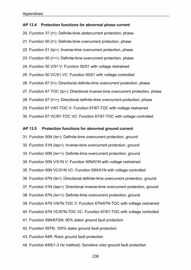
Appendixes
AP 13.4 Protection functions for abnormal phase current
20. Function 37 (I<): Definite-time ubdercurrent protection, phase
21. Function 50 (I>): Definite-time overcurrent protection, phase
22. Function 51 (Ip>): Inverse-time overcurrent protection, phase
23. Function 50 (I>>): Definite-time overcurrent protection, phase
24. Function 50 V/51 V: Function 50/51 with voltage restrained
25. Function 50 VC/51 VC: Function 50/51 with voltage controlled
26. Function 67 (I>): Directional definite-time overcurrent protection, phase
27. Function 67-TOC (Ip>): Directional inverse-time overcurrent protection, phase
28. Function 67 (I>>): Directional definite-time overcurrent protection, phase
29. Function 67 V/67-TOC V: Function 67/67-TOC with voltage restrained
30. Function 67 VC/67-TOC VC: Function 67/67-TOC with voltage controlled
AP 13.5 Protection functions for abnormal ground current
31. Function 50N (Ie>): Definite-time overcurrent protection, ground
32. Function 51N (Iep>): Inverse-time overcurrent protection, ground
33. Function 50N (Ie>>): Definite-time overcurrent protection, ground
34. Function 50N V/51N V: Function 50N/51N with voltage restrained
35. Function 50N VC/51N VC: Function 50N/51N with voltage controlled
36. Function 67N (Ie>): Directional definite-time overcurrent protection, ground
37. Function 51N (Iep>): Directional inverse-time overcurrent protection, ground
38. Function 67N (Ie>>): Definite-time overcurrent protection, ground
39. Function 67N V/67N-TOC V: Function 67N/67N-TOC with voltage restrained
40. Function 67N VC/67N-TOC VC: Function 67/67-TOC with voltage controlled
41. Function 59N/67GN: 90% stator ground fault protection
42. Function 59TN: 100% stator ground fault protection
43. Function 64R: Rotor ground fault protection
44. Function 64R(1-3 Hz method): Sensitive rotor ground fault protection
238
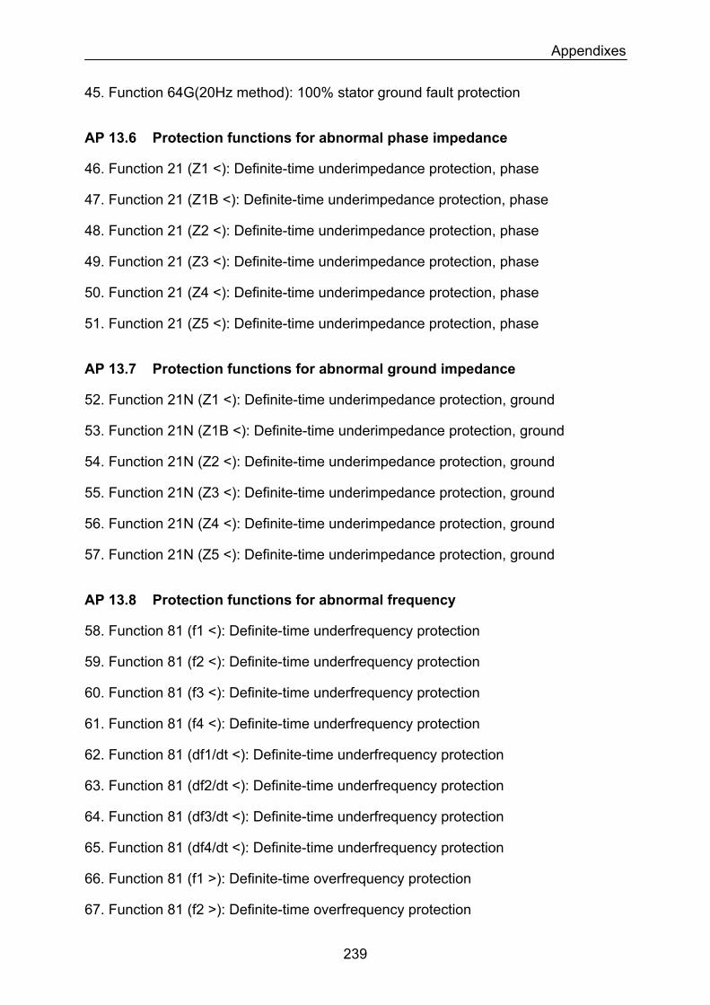
Appendixes
45. Function 64G(20Hz method): 100% stator ground fault protection
AP 13.6 Protection functions for abnormal phase impedance
46. Function 21 (Z1 <): Definite-time underimpedance protection, phase
47. Function 21 (Z1B <): Definite-time underimpedance protection, phase
48. Function 21 (Z2 <): Definite-time underimpedance protection, phase
49. Function 21 (Z3 <): Definite-time underimpedance protection, phase
50. Function 21 (Z4 <): Definite-time underimpedance protection, phase
51. Function 21 (Z5 <): Definite-time underimpedance protection, phase
AP 13.7 Protection functions for abnormal ground impedance
52. Function 21N (Z1 <): Definite-time underimpedance protection, ground
53. Function 21N (Z1B <): Definite-time underimpedance protection, ground
54. Function 21N (Z2 <): Definite-time underimpedance protection, ground
55. Function 21N (Z3 <): Definite-time underimpedance protection, ground
56. Function 21N (Z4 <): Definite-time underimpedance protection, ground
57. Function 21N (Z5 <): Definite-time underimpedance protection, ground
AP 13.8 Protection functions for abnormal frequency
58. Function 81 (f1 <): Definite-time underfrequency protection
59. Function 81 (f2 <): Definite-time underfrequency protection
60. Function 81 (f3 <): Definite-time underfrequency protection
61. Function 81 (f4 <): Definite-time underfrequency protection
62. Function 81 (df1/dt <): Definite-time underfrequency protection
63. Function 81 (df2/dt <): Definite-time underfrequency protection
64. Function 81 (df3/dt <): Definite-time underfrequency protection
65. Function 81 (df4/dt <): Definite-time underfrequency protection
66. Function 81 (f1 >): Definite-time overfrequency protection
67. Function 81 (f2 >): Definite-time overfrequency protection
239
Appendixes
68. Function 81 (f3 >): Definite-time overfrequency protection
69. Function 81 (f4 >): Definite-time overfrequency protection
70. Function 81 (df1/dt >): Definite-time overfrequency protection
71. Function 81 (df2/dt >): Definite-time overfrequency protection
72. Function 81 (df3/dt >): Definite-time overfrequency protection
73. Function 81 (df4/dt >): Definite-time overfrequency protection
AP 13.9 Protection functions for abnormal differential phase current
74. Function 87(low impedance): Phase Differential protection, low impedance relay
75. Function 87(high impedance): Phase Differential protection, high impedance relay
AP 13.10 Protection functions for abnormal differential ground current
76. Function 87N(low impedance): Ground differential protection, low impedance relay
77. Function 87N(high impedance): Ground differential protection, high impedance relay
AP 13.11 Other protection function.
78. Function 21FL: Fault locator
79. Function 25: Synchronizing (paralleling) device, synchronous check
80. Function 50BF: Breaker failure protection
81. Function 79: Autoreclose
82. Function 85: Pilot (Point to Point) communication, teleprotection
83. Function 86: Lockout function
240