experiments on reinforced concrete frames with brick · pdf fileexperiments on reinforced...
TRANSCRIPT

Paper 085
Experiments on Reinforced Concrete Frames with
Brick Infill
2012 NZSEE
Conference
Tsung-Chih Chiou & Shyh-Jiann Hwang
Department of Civil Engineering, National Taiwan University, Taipei City, Taiwan.
Fu-Pei Hsiao
Associate Research Fellow, National Centre for Research on Earthquake Engineering, Taipei City, Taiwan.
ABSTRACT: Brick walls constrained by a reinforced concrete (RC) frame on all four
sides are quite often used in low-rise RC buildings. According to earthquake
reconnaissance, a brick infilled wall is one of the major resistances of preventing building
collapse. Therefore, understanding the seismic behavior of a brick infilled wall is
essential in evaluating the seismic resistance of existing low-rise RC buildings. This
research is aimed at examining the seismic behavior of brick infilled walls. Four full-
scale RC frames with 200mm thickness brick walls were tested under cyclic loading. The
main variables were the brick infilled walls with and without an inner-tied column, and
the compression strength of mortar. The testing results indicated that the boundary
columns and the inner-tied column of RC frame with brick infill were in shear failure. As
well as, the ultimate lateral strength of brick infilled walls with an inner-tied column was
1.7 times of that of brick infilled wall without an inner-tied column. The increased
compression strength of mortar was also beneficial to the seismic behavior of brick
infilled walls. Test results showed that the RC frame could still have a mild negative
slope of strength degradation for its post-strength behavior.
1 INTRODUCTION
Brick walls constrained by a reinforced concrete (RC) frame on all four sides are quite often used in
low-rise RC buildings in the world such as China (Hori et al. 2006), Indonesia (Sanada et al. 2009),
India (Sivarama Sarma et al. 2003), Mexico (Tena-Colunga et al. 2009), Chile (Gent Franch et al.
2008), and Taiwan (Tu et al. 2010). Typical low-rise RC school buildings and arcade buildings in
Taiwan have a common structural system, where adjacent classrooms or arcade buildings are divided
by fully brick infilled wall partitions and the elevations normal to the partitions are opened with doors
and windows. For this reason, these school buildings and arcade buildings have strong seismic capaci-
ty along the partitions direction. Thus, a brick wall is one of the major resistances of preventing build-
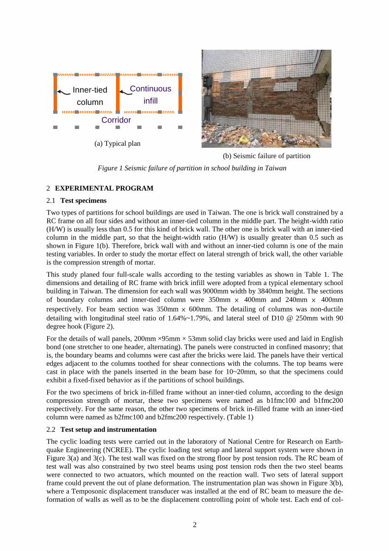
ing collapse (Figure 1(a)).
According to earthquake reconnaissance (Figure 1(b)), the major failure mode of a brick infill wall is
horizontal slips in the centric part of brick wall and inclined diagonal shear cracks in the side part of
brick wall. These shear cracks also extend into the boundary column as well as induce shear failure in
the bottom of column. That is to say, the uncracked part of brick wall can restrain the columns of RC
frame and induce short effective length of column.
Seismic assessments for RC frame with a brick infill are complicated because they combine the behav-
iors of RC frame, masonry panel, and the interactions between frame and panel. Nowadays, practical
guidance for the seismic evaluation for RC buildings with brick infill can be found in FEMA 356
(FEMA 2000), and Chung et al. (2009), where a brick infill panel can be considered as an equivalent
compressive strut. However, these methods can not simulate the phenomenon of shear failure in
boundary columns as shown in Figure 1(b). This research is aimed at examining the seismic behavior
of RC frame with brick infill.
2
Inner-tied
column
Continuous
infill
Corridor
(a) Typical plan
(b) Seismic failure of partition
Figure 1 Seismic failure of partition in school building in Taiwan
2 EXPERIMENTAL PROGRAM
2.1 Test specimens
Two types of partitions for school buildings are used in Taiwan. The one is brick wall constrained by a
RC frame on all four sides and without an inner-tied column in the middle part. The height-width ratio
(H/W) is usually less than 0.5 for this kind of brick wall. The other one is brick wall with an inner-tied
column in the middle part, so that the height-width ratio (H/W) is usually greater than 0.5 such as
shown in Figure 1(b). Therefore, brick wall with and without an inner-tied column is one of the main
testing variables. In order to study the mortar effect on lateral strength of brick wall, the other variable
is the compression strength of mortar.
This study planed four full-scale walls according to the testing variables as shown in Table 1. The
dimensions and detailing of RC frame with brick infill were adopted from a typical elementary school
building in Taiwan. The dimension for each wall was 9000mm width by 3840mm height. The sections
of boundary columns and inner-tied column were 350mm × 400mm and 240mm × 400mm
respectively. For beam section was 350mm × 600mm. The detailing of columns was non-ductile
detailing with longitudinal steel ratio of 1.64%~1.79%, and lateral steel of D10 @ 250mm with 90
degree hook (Figure 2).
For the details of wall panels, 200mm ×95mm × 53mm solid clay bricks were used and laid in English
bond (one stretcher to one header, alternating). The panels were constructed in confined masonry; that
is, the boundary beams and columns were cast after the bricks were laid. The panels have their vertical
edges adjacent to the columns toothed for shear connections with the columns. The top beams were
cast in place with the panels inserted in the beam base for 10~20mm, so that the specimens could
exhibit a fixed-fixed behavior as if the partitions of school buildings.
For the two specimens of brick in-filled frame without an inner-tied column, according to the design
compression strength of mortar, these two specimens were named as b1fmc100 and b1fmc200
respectively. For the same reason, the other two specimens of brick in-filled frame with an inner-tied
column were named as b2fmc100 and b2fmc200 respectively. (Table 1)
2.2 Test setup and instrumentation
The cyclic loading tests were carried out in the laboratory of National Centre for Research on Earth-
quake Engineering (NCREE). The cyclic loading test setup and lateral support system were shown in
Figure 3(a) and 3(c). The test wall was fixed on the strong floor by post tension rods. The RC beam of
test wall was also constrained by two steel beams using post tension rods then the two steel beams
were connected to two actuators, which mounted on the reaction wall. Two sets of lateral support
frame could prevent the out of plane deformation. The instrumentation plan was shown in Figure 3(b),
where a Temposonic displacement transducer was installed at the end of RC beam to measure the de-
formation of walls as well as to be the displacement controlling point of whole test. Each end of col-

3
umns installed a tiltmeter to monitor rotation angle of flexure deformation. For the local deformation
of brick wall, several image based markers were stuck on the wall surface. Two dial gauges were in-
stalled between the RC beam and steel beam, and between the RC foundation and strong floor to mon-
itor the sliding displacement of these two interfaces respectively. Cyclic loading procedure was shown
in Figure 3(d). The procedure was controlled by drift ratio, which is the displacement of Temposonic
divided by 2900mm. The procedure began with drift ratio of 0.125%, 0.175%, up to 4%. Three cycles
were tested for each drift ratio. Test would be terminated while the residual strength less than 80% of
ultimate strength.
Table 1. Testing parameters of the experiment
Brick in-filled frame Compression strength of mortar (MPa)
10 20
without an inner-tied column
b1fmc100
b1fmc200
with an inner-tied column
b2fmc100
b2fmc200
Figure 2 Dimensions and details of the test walls

4
(a) cyclic loading test setup
(b) instrument plan
(c) test setup of lateral support system
Dis
pla
ce
me
nt
co
ntr
ol
Drift ratio(%).125 .175 .25 .3
75 .5 .75 1 1.5 2 3 4 6
x3
-5
-4
-3
-2
-1
0
1
2
3
4
5
DR
IFT
RA
TIO
(%)
0 3 6 9 12
CYCLE15 18 21 24 27 30
-6
6
Loading History according to
ACI T1.1R -01 : Commentary on Acceptance Criteria for Moment
Frames Based on Structural Testing
(d) cyclic loading procedure
Figure 3 Test plan
3 EXPERIMENTAL RESULTS
3.1 Material property
The material testing results were shown in Table 2. The testing results of compressing strength of con-

5
crete were 25MPa, 27MPa, 30MPa, and 28MPa respectively; The original design compressing
strength of mortar were 10MPa and 20MPa but the testing results were 7MPa, 13MPa, 7MPa, and
10MPa respectively; For the compression strength of solid brick was 38MPa, and the tension yield
strength of steels were 349MPa and 412MPa for D10 and D19 respectively.
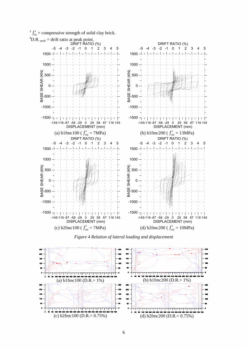
3.2 Loading-deformation curves and crack patterns
3.2.1 Specimen b1fmc100
The hysteretic loop of loading- deformation of the specimen b1fmc100 was shown in Figure 4(a). The
ultimate lateral strength was 668kN, while the drift ratio was at 0.75%. In this stage, the major failure
patterns were horizontal slips in the centric part of brick wall and inclined diagonal shear cracks in the
side part of brick wall. The bottoms of both boundary columns also occurred diagonal shear failure at
1.0% drift (Figure 5(a)). This test was terminated at 2.0% drift while the residual strength was 45% of
ultimate strength.
3.2.2 Specimen b1fmc200
The hysteretic loop of loading- deformation of the specimen b1fmc200 was shown in Figure 4(b). The
ultimate lateral strength was 847kN at the fist drift of 0.125%, while the major failure patterns were
horizontal slips in the centric-upper part of brick wall. The lateral strength deceased rapidly to 57% of
ultimate strength at 1% drift, meanwhile the tops and bottoms of both boundary columns occurred di-
agonal shear failure. However, the strength remained about 60% at 2% even a little increased at 3%
drifts. This test was terminated at the third cycle of 4.0% drift while the residual strength was 30% of
ultimate strength.
3.2.3 Specimen b2fmc100
The hysteretic loop of loading- deformation of the specimen b2fmc100 was shown in Figure 4(c). The
ultimate lateral strength was 1177kN, while the drift ratio was at -0.5% in pulling direction. In this
stage, the major failure patterns were inclined diagonal shear cracks in the both brick walls. The bot-
toms of both boundary columns and the middle of inner-tied column also occurred diagonal shear fail-
ure at 0.75% drift (Figure 5(c)). This test was terminated at 2.0% drift while the residual strength was
42% of ultimate strength.
3.2.4 Specimen b2fmc200
The hysteretic loop of loading- deformation of the specimen b2fmc200 was shown in Figure 4(d). The
ultimate lateral strength was 1327kN, while the drift ratio was at 0.5%. In this stage, the major failure
patterns were inclined diagonal shear cracks in the both brick walls. The bottoms of both boundary
columns and the middle of inner-tied column also occurred diagonal shear failure at 0.75% drift (Fig-
ure 5(d)). This test was terminated at 3.0% drift while the residual strength was 18.8% of ultimate
strength.
Table 2. Test result
Specimen cf ,1
MPa
mcf ,2
MPa
bcf ,3
MPa
yf
MPa Vpeak
kN
Δpeak
mm
D.R. peak4
% #3 #6
b1fmc100 25 7 38 349 412 668 21.46 0.75
b1fmc200 27 13 38 349 412 847 3.35 0.125
b2fmc100 30 7 38 349 412 1177 -14.2 -0.5
b2fmc200 28 10 38 349 412 1327 14.2 0.5
1cf = compressive strength of concrete of beam and column members.
2mcf = compressive strength of mortar.
6
3
bcf = compressive strength of solid clay brick. 4D.R. peak = drift ratio at peak point.
(a) b1fmc100 ( mcf = 7MPa)
(b) b1fmc200 ( mcf = 13MPa)
(c) b2fmc100 ( mcf = 7MPa)
(d) b2fmc200 ( mcf = 10MPa)
Figure 4 Relation of lateral loading and displacement
(a) b1fmc100 (D.R.= 1%)
(b) b1fmc200 (D.R.= 1%)
(c) b2fmc100 (D.R.= 0.75%)
(d) b2fmc200 (D.R.= 0.75%)

7
Figure 5 Crack patterns (D.R.= Drift Ratio)
4 DISCUSSION OF TEST VARIABLES
4.1 Effects of inner-tie column
The envelopes of loading-deformation curves were shown in Figure 6. For the two walls with lower
compression strength of mortar, the ultimate lateral strength of brick wall with an inner-tied column
was 1.76 times of that of brick wall without an inner-tied column as below,
76.11001
1002
fmcb
fmcb
V
V (1)
Likewise, for the two walls with higher compression strength of mortar, the ultimate lateral strength of
brick wall with an inner-tied column was 1.57 times of that of brick wall without an inner-tied column
as below,
57.12001
2002
fmcb
fmcb
V
V (2)
The brick walls with an inner-tied column, H/W > 0.5, occurred many inclined diagonal cracks (Figure
5(c) and 5(d)). Since inclined diagonal cracks made solid brick splitting, the strength of inclined diag-
onal cracks was absolutely higher than that of horizontal slips. Consequently, the more inclined diago-
nal cracks, the higher lateral strength. On the contrary, the brick walls without an inner-tied column,
H/W < 0.5, occurred few inclined diagonal cracks (Figure 5(a) and 5(b)) thus got lower lateral strength.
4.2 Effects of mortar compressive strength
For the two walls without an inner-tied column (Figure 6), the increment of compression strength of
mortar was 6713 mcf MPa
and the increment of lateral strength of walls was
847 668 179V kN. Thus, the contribution to lateral strength per unit increment of compression
strength of mortar could be illustrated as
8.296
179
mcf
V (3)
Moreover, for the two walls with an inner-tied column (Figure 6), the increment of compression
strength of mortar was 3710 mcf MPa and the increment of lateral strength of walls was
1327 1177 150V kN. Thus, the contribution to lateral strength per unit increment of compres-
sion strength of mortar could be illustrated as
503
150
mcf
V (4)
This simple analysis indicated that compression strength of mortar was sensitive parameters to the
brick walls with an inner-tied column. This was because that the higher compression strength of mor-
tar got the higher friction strength and splitting strength of the interface between solid brick and mortar.
As well as, comparison of the failure patterns (Figure 5(a) and 5(c)) could show that the abundant in-
clined diagonal cracks and horizontal cracks occurred in the brick walls with an inner-tied column but
the major failure of the brick walls without an inner-tied column was horizontal slips. Thus, compres-
sion strength of mortar was sensitive for lateral strength of the brick walls with an inner-tied column.
5 CONCLUSIONS
The study carried out four full-scale RC frames with brick infill. Two testing variables, including brick
with and without inner-tied column, and compression strength of mortar, were studied on seismic be-
havior of RC frames with brick infill. The following conclusions could be drawn.
(A) Testing results indicated that the columns of RC frame with brick infill were shear failure since

8
that uncracked part of brick wall could restrain the columns of RC frame and induced short
effective length of column.
(B) The brick walls with an inner-tied column, H/W > 0.5, occurred more inclined diagonal cracks
and got the higher lateral strength.
(C) The compression strength of mortar obviously contributed on lateral strength of the brick walls,
especially for the brick walls with an inner-tied column.
Figure 6 Envelopes of loading-deformation curves
6 ACKNOWLEDGEMENT
The study was funded by the National Centre for Research on Earthquake Engineering, Taiwan,
through grant NCREE 100A1300. The authors gratefully acknowledged the NCREE staff for
supporting the experiment.
REFERENCES:
Chung L.L., Yeh Y.K., Chien W. Y., Hsiao F. P., Shen W. C., Chiou T. C., Chow T. K., Chao Y. F., Yang Y. S., Tu Y. S., Chai J. F., Hwang S. J. and Sun C. H. 2009. Technology Handbook for Seismic Evaluation and Retrofit of School Buildings - Second Edition. National Centre for Research on Earthquake Engineering Report. No 09-023 (in Chinese), Taipei, Taiwan.
FEMA 356. 2000. Prestandard and Commentary for the Seismic Rehabilitation of Buildings. Federal Emergency Management Agency Report. Washington D.C..
Gent Franch K. A., Giuliano Morbelli G., Astroza Inostroza M. A., and Gori R. E. 2008. A seismic vulnerability index for confined masonry shear wall buildings and a relationship with the damage. Engineering Structures, Vol. 30, 2605-2612.
Hori N., Inoue N., Purushotam D., Nishida T., and Kobayashi J. 2006. Experimental and analytical studies on earthquake resisting behaviour of confined concrete block masonry structures. Earthquake Engineering and Structural Dynamics, Vol. 35, 1699-1719.
Sanada S., Kishimoto I., Kuroki M., Sakashita M., Choi H., and Tani M. 2009. Preliminary report on damage to buildings due to the September 2 and 30, 2009 earthquakes in Indonesia. Proceedings of the 11
th Taiwan-
Korea-Japan Joint seminar on earthquake engineering for building structures, Kyoto, Japan, 297-306.
Sivarama Sarma B., Sreenath H. G., Bhagavan N. G., Ramachandra Murthy A., and Vimalanandam V. 2003. Experimental studies on in-plane ductility of confined masonry panels. ACI Structural Journal, Vol. 100, No.3, 330-36.
Tena-Colunga A., Juárez-Ángeles A., and Salinas-Vallejo V. H. 2009. Cyclic behavior of combined and confined masonry walls. Engineering Structures, Vol. 31, 240-259.
Tu Y. H., Chuang T. H., Liu P. M., and Yang Y. S. 2010. Out-of-plane shaking table tests on unreinforced masonry panels in RC frames. Engineering Structures, Vol. 32, 3925-3935.