experimental study of a square foundation with connected ...€¦ · underlying soil on the...
TRANSCRIPT

Civil Engineering Infrastructures Journal, 52(1): 185 – 203, June 2019
Print ISSN: 2322-2093; Online ISSN: 2423-6691
DOI: 10.22059/ceij.2019.261279.1498
* Corresponding author. E-mail address: [email protected]
185
Experimental Study of a Square Foundation with Connected and Non-
Connected Piled Raft Foundation Under Eccentrically Loaded
Saeedi Azizkandi, A.R.1*, Taherkhani, R.2 and Taji, A.3
1 Assistant Professor, School of Civil Engineering, Iran University of Science and
Technology, Tehran, Iran. 2 M.Sc., School of Civil Engineering, Iran University of Science and Technology, Tehran,
Iran. 3 M.Sc., School of Civil Engineering, Iran University of Science and Technology, Tehran,
Iran.
Received: 02 Jul. 2018; Revised: 12 Jan. 2019; Accepted: 20 Jan. 2019
ABSTRACT: In the recent years, non-connected piled raft foundation has been considered
as an economical and practical deep foundation in the situation that high shear and
concentrated loads may occur at the connection of the raft and pile head. This paper was
presented an experimental study of a square foundation on the effects of parameters such as
S/D, L/D and etc. in two cases of connected or non-connected piled raft system under the
eccentrically loaded raft. The results was showed that square raft in the case of S/D = 3 and
L/D = 8, the bearing capacity of the non-connected piles is more than that of the connected
piles. The results of the experiments was showed pile length is more effective than the pile
spacing in connected pile raft system. However by decreasing pile spacing, bearing capacity
is increased in non-connected pile raft and pile spacing is more effective than the pile spacing
in non-connected pile raft system. Comparison of bearing capacity and settlement indicated
in the non-connected piled raft system, the longer piles not only has not much effect in
increasing bearing capacity significantly, but also has lower effect on the reduction of the
settlement. Also in non-connected piled raft system by increasing the pile spacing reduced
BPI (bearing pile index) wile in connected piled raft system increased.
Keywords: Bearing Capacity, Connected Piled Raft, Eccentrically Loaded, Non-Connected
Piled Raft, Settlement.
INTRODUCTION
Piles are usually used in foundations for two
major reasons: supplying the required bearing
capacity and reducing settlement to an
acceptable level. In some cases, the shallow
layers of the soil have sufficient bearing
capacity, but the foundation can experience
very large settlements. In these cases, piles are
used with foundations. Using piles for the
reduction of the foundation settlements as
well as increasing the bearing capacity was
proposed by Burland et al. (1977) at first.
Prakoso and Kulhawy (2001) reported on the
effect of foundation geometry and pile group
on the average of various settlements and
bending moments. Reul and Randolph
(2004) presented a parametric study on the

Saeedi Azizkandi, A.R. et al.
186
effect of the position, number and the length
of piles as well as the stiffness of the
underlying soil on the behavior of a piled raft.
Rabiebi (2009) conducted studies on a piled
raft system on the clay soil. Nakanishi and
Takewaki. (2013) investigated the optimal
arrangement of piles to reduce the different
settlements of piled raft foundation systems.
According to these studies, the increasing
of the thickness of the foundation besides
reducing the number and length of the piles
will lead to the increase of the maximum
bending moments in the foundation. When
the piles are employed for the reduction of the
settlement, all of the geotechnical bearing
capacity of the piles could be used. This
condition would cause very large axial
stresses in the pile, therefore, to increase the
bearing capacity of the pile and to prevent
structural damage, the dimensions of the pile
need to be extended. This will lead to the
uneconomical design of the foundation
system. Therefore, to avoid large stresses
between the foundation and the pile, several
researchers suggested that the pile should be
separated from the foundation so that,
instead of a structural element, it functions as
a reinforcement element in the soil. In seismic
zones, if piles are attached to the rafts, due
to the cyclic or dynamic lateral forces, large
shear forces as well as overturning moments
are created at the connection of the piles to the
raft.
To develop an analytical and seismic
optimum design method, Nemoto et al.
(2006) and Rajib et al. (2015) conducted a
series of analytical and laboratory studies on
the model behavior of pile groups in the dry
sand under both static and cyclic lateral loads.
Mahmood et al. (2018) presented the three-
dimensional analysis for the dynamic
response of a piled raft foundation subjected
to vertical vibration. They showed that
increasing the distance between the
foundation and the boundaries and increasing
the relative density of the sand can
significantly minimize the dynamic response
of the foundation.
Although foundations with non-connected
piles function appropriately in dynamic
conditions, they should also respond properly
in static conditions, as well. Cao et al. (2004)
analyzed the behavior of foundations with
non-connected piles on sandy soils and
observed the foundation response to the
change of some parameters such as stiffness,
length, arrangement, and the number of piles.
The results of the study displayed the
important characteristic of the non-connected
piles in reducing the settlement and bending
moment.
Fioravante and Giretti (2010), using
centrifugal modeling, studied the load
transfer mechanism in the piled raft system.
They also examined the effect of gravel layer
on the stiffness of the underlying system in
dense, dry sand. They controlled the relative
settlement mechanism between the pile and
the soil by changing the thickness and
stiffness of both middle and bottom layers of
the soil.
Saeedi Azizkandi and Fakher (2014) wrote
a computer program based on the Finite
Element Method (FEM) for analyzing piled
raft foundation and comparison of different
concepts of pile group design. In this
program, a foundation is modeled as a
flexible plate, soil and pile are modeled by
Winkler springs. Taghavi Ghalesari and
Janalizadeh Choobbasti (2016) showed that
the bearing capacity of piled raft obviously
increased with increasing pile length, pile
spacing, and raft thickness, especially in stiff
clay by numerical analyses.
Sinha et al. (2016) investigated a
numerical study on piled raft system to
examine the role of the foundation geometry,
including pile spacing in the group, pile
length, pile shape, pile diameter, and raft
thickness by the software of ABAQUS. They
studied the influence of the mechanical
properties of the surrounding soils on the

Civil Engineering Infrastructures Journal, 52(1): 185 – 203, June 2019
187
load-sharing mechanism.
Jamshidi Chenari et al. (2018) studied the
effect of spatial variability of soil parameters
on the bearing capacity of piled raft
foundation based on the random field theory
using the Finite Difference software of
FLAC3D. Ruping Luo et al. (2018) performed
to investigate the variation of the normalized
settlement of the piled raft, including the
effects of soil condition, pile dimensions, and
soil-pile adhesion. They presented a practical
analytical method for a piled raft in clay,
Based on the three-dimensional boundary
element method. Vikas Kumar and Arvid
Kumar (2018) concluded that as the number
of settlement-reducing piles increased, the
load improvement ratio increased and the
differential settlement ratio decreased.
One of the problems that may arise during
employing non-connected piled raft
foundations is applying eccentric loads to the
foundations. In severe wind and seismic
prone areas, due to the lateral loads, the
foundation is exposed to eccentric loads that
may lead to rotating of the foundation,
especially in tall buildings. The application of
a pile-foundation system in such cases
increases the sustainability of the building
and reduces the rotation of the foundation.
In order to investigate the performance of
the non-connected piled foundation system
under eccentrically loaded, El-Sawwaf
(2010) conducted a laboratory study on a strip
foundation with both connected and non-
connected piles on the sand and investigated
the effect of the length, number and
arrangement of piles. Patil et al. (2016) also
studied the bearing capacity as well as the
settlement rate for a strip foundation with
non-connected piles located on the sandy soil
under eccentrically loaded.
Rasouli et al. (2015), using the centrifugal
modeling, compared the behaviors of both
connected and non-connected foundations for
two modes of increasing the bearing capacity
and the reduction of settlement. This study
aims to examine the response of both
connected and non-connected piled
foundation systems to the variation of some
parameter such as the number of piles, the
distance between the piles and the thickness
of the gravel layer.
Although most foundations are exposed to
lateral and eccentric loads during their
lifespan, little studies have compared the
behavior of both connected piled raft
foundations and non-connected piled raft
foundations under eccentric loading. The
study carried out by El-Sawwaf (2010) and
Patil et al. (2016) on foundations with non-
connected piles only covered strip
foundations, while other types of foundations
were not included. Also, many researchers
investigated about non-connected piled raft
under dynamic loads (Saeedi azizkandi et al.,
2017; Cao et al., 2004).
The main objective of this study was to
consider the load-settlement diagrams of a
square foundation with both connected and
non-connected piles located on the sandy soil
under eccentric loading. This was performed
through conducting 14 experiments and
changing some parameters such as the degree
of eccentricity from the axis (e), the length of
the pile (L) and the distance between piles
(S). The foundation behavior is then
evaluated for each case through comparison
of the load-settlement curves.
MODELING BOX AND FOUNDATION
In order to model the laboratory conditions, a
metal box with dimensions of 0.8 m, 1.2 m
and a height of 1 m was used. This box was
made of three steel walls with a thickness of
10 mm and a glass wall with a thickness of
20 mm. The walls of the box were supported
by 4 columns (IPE14) and 4 beams (IPE12).
The loading system was installed
horizontally and included an IPE10 beam that
was connected to the horizontal beams and
supported the beam (Figure 1). In order to
Saeedi Azizkandi, A.R. et al.
188
apply forces, a hydraulic jack was used. The
maximum power of the jack piston was 15
tons (Figure 2).
The load is applied onto a platform by a
piston. The platform lets eccentric loading
insert onto a base and then onto the foundation.
The platform was constructed in a way that lets
the eccentric loading be applied in two
distances (10 and 20 mm) away from the center
of the foundation and also in different
directions (Figure 3).
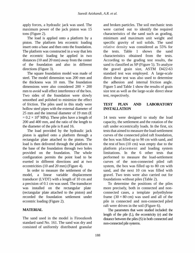
The square foundation model was made of
steel. The model dimension was 200 mm and
the thickness was 10 mm. The foundation
dimensions were also considered 200 × 200
mm to avoid wall effect interference of the box.
Two sides of the foundation were slowly
smoothed and polished to minimize the effect
of friction. The piles used in this study were
hollow steel pipes with the external diameter of
25 mm and the internal diameter of 19 mm (E
= 0.2 × 10⁶ MPa). These piles have a length of
200 and 400 mm, and the ratio of the length to
the diameter of the pile is 8 and 16.
The load provided by the hydraulic jack
piston is applied onto a platform through a
rectangular plate attached to the piston. The
load is then delivered through the platform to
the base of the foundation through two holes
provided on the foundation. The whole
configuration permits the point load to be
exerted in different directions and at two
eccentricities (10 and 20 mm) (Figure 4).
In order to measure the settlement of the
model, a linear variable displacement
transducer (LVDT) with a length of 10 cm and
a precision of 0.1 cm was used. The transducer
was installed on the rectangular plate
(rectangular plate attached to the piston) and
recorded the foundation settlement under
eccentric loading (Figure 2).
MATERIAL
The sand used in the model is Firoozkooh
standard sand No. 161. The sand was dry and
consisted of uniformly distributed granular
and broken particles. The soil mechanic tests
were carried out to identify the required
characteristics of the sand such as grading,
minimum and maximum unit weight and
specific gravity of soil solids. The sand
relative density was considered as 55% for
the tests. Table 1 shows the sand
characteristics obtained from the tests.
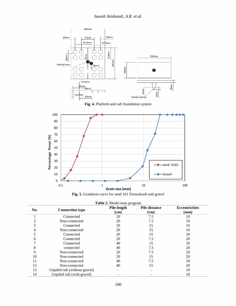
According to the grading test results, the
sand is classified as SP (Figure 5). To analyze
the gravel grain size, ASTM D422-63
standard test was employed. A large-scale
direct shear test was also used to determine
the adhesion and internal friction angle.
Figure 5 and Table 1 show the results of grain
size test as well as the large-scale direct shear
test, respectively.
TEST PLAN AND LABORATORY
INSTALLATION
14 tests were designed to study the load
capacity, the settlement and the rotation of the
raft under eccentrically loads. In the first, six
tests that aimed to measure the load-settlement
curves of the connected piled raft foundation,
the box was filled up to 90 cm with sand, and
the rest of box (10 cm) was empty due to the
platform placement and loading system
limitations. In the 6 other tests that
performed to measure the load-settlement
curves of the non-connected piled raft
system, the box was filled up to 80 cm with
sand, and the next 10 cm was filled with
gravel. Two tests were also carried out for
foundations without piles (Table 2).
To determine the positions of the piles
more precisely, both in connected and non-
connected cases, a template polyethylene
frame (30 × 80 cm) was used and all of the
pile in connected and non-connected piled
raft were driven in the soil (Figure 6).
The parameters that were studied included: the
length of the pile (L), the eccentricity (e) and the
distance between the piles (S) in both connected and
non-connected pile systems.

Civil Engineering Infrastructures Journal, 52(1): 185 – 203, June 2019
189
Fig. 1. Schematic view of the experimental apparatus
Fig. 2. Loading system (hydraulic jack with bearing plate)
Fig. 3. Pile raft foundation (raft and pile with platform)
Table 1. Physical properties of Iran’s Firouzkouh sand No. 161 and gravel
Relative density
(%) 𝑮𝑺 𝒆𝒎𝒂𝒙 𝒆𝒎𝒊𝒏 𝑫𝟓𝟎 (𝒎𝒎) 𝛗° 𝑪 (𝑲𝑵 𝒎𝟐)⁄
F.C
(%) 𝑪𝒖 𝑪𝒄
Sand
type
55 2.66 0.97 0.55 0.3 32 5 0.2 2.58 0.97 Sand-
161
5 2.6 0.6 0.3 10 40 4.2 0 1.67 1.07 Gravel
1. Loading beam
2. Glass wall
3. Supported beam for cylinder
4. Supported beam
5. Cylinder
6. Bearing plate
Saeedi Azizkandi, A.R. et al.
190
Fig. 4. Platform and raft foundation system
Fig. 5. Gradation curve for sand 161 Firouzkouh and gravel
Table 2. Model tests program
No. Connection type Pile length Pile distance Eccentricities
(cm) (cm) (mm)
1 Connected 20 7.5 10
2 Non-connected 20 7.5 10
3 Connected 20 15 10
4 Non-connected 20 15 10
5 Connected 20 15 20
6 Connected 20 7.5 20
7 Connected 40 15 20
8 connected 40 7.5 20
9 Non-connected 20 7.5 20
10 Non-connected 20 15 20
11 Non-connected 40 7.5 20
12 Non-connected 40 15 20
13 Unpiled raft (without gravel) - - 10
14 Unpiled raft (with gravel) - - 10
0
10
20
30
40
50
60
70
80
90
100
0.1 1 10 100
Per
cen
tage
fin
ner
(%
)
Grain size (mm)
sand- D161
Gravel

Civil Engineering Infrastructures Journal, 52(1): 185 – 203, June 2019
191
The laboratory model tests for non-connected pile
The laboratory model tests for connected pile
a) Step 1. Filing the box with sand (80 cm)
b) Step 1. Filing the box with sand (90 cm)
c) Step 2. Driving the piles in sandy layer
d) Step 2. Piled raft assembling
e) Step 3. Filling the gravel (10 cm)
f) Step 3. Driving the piles in sandy layer

Saeedi Azizkandi, A.R. et al.
192
g) Step 4. Placing the raft on the gravel
h) Step 4. Placing the raft on the sand
Fig. 6. The laboratory model tests for connected and non-connected pile
RESULTS AND DISCUSSION
Based on the modeling conditions, the
behavior of the foundation was investigated in
both connected and non-connected piles
under eccentric loading. In order to evaluate
the bearing capacity and settlement, the
parameters of soil improvement, the length,
and distance of piles, eccentricity and
bearing pressure improvement (BPI) were
used. The relative improvement of the raft
performance is represented using a non-
dimensional factor, called the Bearing
Pressure Improvement (BPI). This factor is
defined as the ratio of the bearing pressure of
a piled raft (qpiled), to the bearing pressure of
an un-piled raft (qun-piled) at the same
settlement level. The raft settlement (S) was
also analyzed in a non-dimensional form in
terms of the raft width (B) as the ratio (S/B,
%). In this paper, all percentages of the
increase in the bearing capacity of tests are
compared to un-piled.
Bearing Capacity and Soil Improvement
Soil Improvement Using Piles
Figure 7 shows the variations of the
foundation bearing capacity in both cases of
connected and non-connected piles for S/D =
3, L/D = 8, e/B = 0.1, in the state of the piled
and un-piled. All tests were performed in both
modes of with and without a 10 cm gravel
layer. Figure 7 clearly shows that the bearing
capacity of both connected and non-
connected piles is higher than that of the un-
piled foundation. As shown in Figure 7, the
bearing capacity of foundation with S/D = 3
and non-connected piles (19.5 kg/cm2) is
higher than that of the connected piles (17.5
kg/cm2). Therefore, foundations with non-
connected piles have greater bearing
capacities than the connected piles. This
means about 85% increase in bearing capacity
for non-connected mode (S/D = 3), and 67%
increase for connected mode.
Figure 7 also shows that the bearing
capacity is greater when the gravel cushion is
used (13.5 kg/cm2), comparing to the tests in
which the cushion layer is not used (10.5
kg/cm2). This means a 28% improvement in
the bearing capacity. Figure 7 generally
shows that the use of foundations with non-
connected piles improves the bearing
capacity of the foundation and in some cases
where the pile spacing is 7.5 cm, it can even
enhance the bearing capacity, comparing to
the connected pile's mode.
The Effect of Pile Length
Figure 8 shows the variations of the
bearing capacity for both connected and non-
connected piles cases where L/D = 8 and e/B
= 0.1. As shown in Figure 8, in the case of the
length of pile is 7.5 cm (S/D = 3), the bearing
capacity of the foundation with non-
connected piles is greater than that of the
foundation with connected piles, however,

Civil Engineering Infrastructures Journal, 52(1): 185 – 203, June 2019
193
when the length of pile exceeds 15 cm, the
bearing capacity of the connected pile
foundation is greater than non-connected
ones.
This indicates that in the non-connected
mode, as the pile span increases, the bearing
capacity reduces. This can be explained by
the fact that when the pile span decreases in
the non-connected piled raft, the
improvement zone formed under the raft is
more confined and rigid. The rigid elements
of the pile along the cushion layer increase the
bearing capacity and prevent the formation of
a failure ridge. In the non-connected mode,
when the pile spacing increases, the rigidity
of the improved area under the raft reduces.
Unlike the non-connected mode, in
connected mode, the bearing capacity
increases when the pile spacing increases. In
this mode, by the increase of the pile spacing,
the interaction between piles decreases,
leading to an increase in the pile group
bearing capacity.
This paper suggests that the performance
of the long-spanned connected pile
foundation is better than the non-connected
piles under the eccentric loading, whereas, in
non-connected piles, the performance of
short-spanned piles is superior.
The results obtained are also consistent
with previous researches. Cao et al. (2004)
studied a typical loading condition consisting
of a uniformly distributed load in the
central core area and two symmetrical line
loads and reported that concentrating the piles
within the central area of the plate reduced the
settlement at the center, but marginally
increased the settlement at the edge. They
also found that for different pile
arrangements, the bearing capacity is in
reverse relationship with the piles' distance
from the center of the foundation. This is in
line with the results of El-Sawwaf (2010), as
well. The results of their experiments also
showed that in a connected piled raft system,
the bearing capacity of the pile under the
eccentric loading changes inversely with piles'
distance from the center. Likewise, Patille et
al. (2016) showed that in the connected mode,
when a pile is placed in the corners of a
foundation, the bending capacity increases
under the eccentric loading.
Figure 9 shows BPI variations versus L/D
= 8 and L/D = 16. According to Figure 9, the
maximum BPI value is equal to 2.18 which
results from placing a 40 cm-long pile at a
distance of 15 cm from the center. Figure 9
also indicates that BPI is higher for
connected piles compared to non-connected
piles. Therefore, in order to increase the load
bearing capacity, the connected piles have a
better performance than the non-connected
piles. According to Figure 9, a connected
foundation with piles spanned at 7.5 cm
possesses the highest growth value for BPI.
The Effect of Pile Spacing
Figure 10 shows the variation of the
bearing capacity versus the foundation
settlement for the connected pile mode (e/B
= 0.1). As one can see, the trends in the
diagram show that the bearing capacity for a
40 cm pile length (24.5 kg/cm2) spanned at the
distance of 15 cm from the center of the
foundation is more than that of a 20 cm pile
(20.5 kg/cm2) located at the same distance.
This means a 20% increase in the bearing
capacity. If both 40 cm and 20 cm long piles
are spanned at 7.5 cm from the center of
the foundation, they will improve the
bearing capacity to 22.5 and 18 kg/cm2,
respectively, that means 25% improvement in
the bearing capacity.
Figure 10 obviously shows that the effect
of the pile length is far greater than the effect
of the pile distance. This can be proved by the
comparison of 40 cm long piles in S/D = 8
and S/D = 16 modes that have a greater
bearing capacity than 20 cm long piles. One
can conclude that in a connected piled raft
system, to increase the bearing capacity of the
foundation, extending the length of the piles

Saeedi Azizkandi, A.R. et al.
194
is a more effective solution for soil
improvement rather than increasing the pile
spans.
Another important point is that 20 cm long
piles can increase the bearing capacity of the
foundation up to 114 percent, compared to the
un-piled foundations. However, when the
length of the piles is extended to 40 cm, the
improvement of the load capacity is only
limited to 25%, suggesting that the use of
shorter piles is more economical and effective
in improving the soil, and can cause fewer
tensions to the structure linked to the
foundation, leading to an economic design.
Figure 11 shows the variation of the
bearing capacity versus the foundation
settlements for the non-connected mode. The
trends show that in the non-connected pile
raft system, the 40 cm long pile with S/D = 3
has the highest bearing capacity (21.5
kg/cm2), while the 20 cm long piles have 19.5
kg/cm2. This shows a 10 percent
improvement in the bearing capacity.
Similarly, the 40 and 20 cm long piles show
17.5 and 16 kg/cm2 bearing capacity for S/D
= 6, which means a 9% improvement. Figure
11 clearly shows that for the same distance,
as the length of the pile increases the bearing
capacity increases, as well.
Figure 11 shows that in non-connected pile
raft system, the effect of the pile spacing is
greater than the length of the pile. Also as one
can see in Figure 11, when the piles are
spanned at a distance of 7.5 cm, both in L/D
= 8 and L/D = 16, they possess a higher
bearing capacity compared to the time when
they are at a distance of 15 cm. This again
shows that in a non-connected pile raft
system, by the increase of the rigidity of the
soil located under the foundation and affected
by loading, the bearing capacity approaches
its maximum value.
The comparison of Figures 10 and 11
show that the bearing capacity of the
connected pile raft system with 40 cm long
piles in S/D = 6 is greater than the non-
connected pile mode in S/D = 3. Taking into
account the two factors of "length" and
"distance from the foundation center", one
can conclude that the bearing capacity for
connected pile mode is better than the non-
connected mode.
Fig. 7. The variation of the bearing capacity of the foundation with a connected and non-connected piles in S/D = 3,
L/D = 8 and e/B = 0.05
0
0.5
1
1.5
2
2.5
3
3.5
4
4.5
0 2 4 6 8 10 12 14 16 18 20 22
Sett
lem
en
t (c
m)
P (kg/cm2)
S/D=3,Unconnected
S/D=3,Connected
Unpiled raft-with 10 cmgeravel
Unpiled raft-without geravel

Civil Engineering Infrastructures Journal, 52(1): 185 – 203, June 2019
195
Fig. 8. The variation of the bearing capacity of connected and non-connected piles in L/D = 8 and e/B = 0.05
Fig. 9. The BPI variations versus L/D = 8 and L/D = 16
Figure 12 shows BPI variation for both
connected and non-connected pile raft system
in S/D = 3 and S/D = 6. As the results show,
the highest values (2.33 kg/cm2) occur for
connected 40 cm long pile in S/D = 3 and S/D
= 6. Figure 12 also shows that the 40 cm long
piles have a greater BPI than 20 cm long piles
when placed at a distance of 7.5 cm from the
0
0.5
1
1.5
2
2.5
3
3.5
4
4.5
0 2 4 6 8 10 12 14 16 18 20 22Se
ttle
me
nt
(cm
)P (kg/cm2)
S/D=6,Connected
S/D=3,non-connected
S/D=3,Connected
S/D=6, non-connected
Unpiled raft-with 10 cm geravel
Unpiled raft-without geravel
0.00
0.50
1.00
1.50
2.00
2.50
6 8 10 12 14 16 18
BP
I
L/D
S/D=6,Connected
S/D=3, UnConnected
S/D=6, UnConnected
S/D=3, Connected

Saeedi Azizkandi, A.R. et al.
196
foundation center. However, when the
distance exceeds 15 cm, the BPI value of the
connected piles is greater than that of the non-
connected, indicating that when the distance
exceeds 15 cm, the connectivity or non-
connectivity parameter is more effective than
the pile span. Figure 12 also shows that in
non-connected mode, as the pile span
increases, the BPI value decreases, unlike the
connected mode in which the BPI increases
with the increase of pile span.
Fig. 10. The variation in bearing capacity versus settlement for foundations with connected piles (e/B = 0.1)
Fig. 11. The variation in bearing capacity versus settlement for foundations with non-connected pile (e/B = 0.1)
0
0.5
1
1.5
2
2.5
3
3.5
4
4.5
0 2 4 6 8 10 12 14 16 18 20 22 24 26
Sett
lem
en
t (c
m)
P (kg/cm2)
S/D=6,L/D=16
S/D=3,L/D=16
S/D=6,L/D=8
S/D=3,L/D=8
Unpiled raft-with 10 cmgeravelUnpiled raft-without geravel
0
1
2
3
4
5
6
0 2 4 6 8 10 12 14 16 18 20 22 24
Sett
lem
en
t (c
m)
P (kg/cm2)
S/D=3,L/D=16
S/D=3, L/D=8
S/D=6,L/D=16
S/D=6,L/D=8
Unpiled raft-with 10 cmgeravel
Civil Engineering Infrastructures Journal, 52(1): 185 – 203, June 2019
197
Fig. 12. The BPI variations for S/D = 3 and S/D = 6 for connected and non-connected piles (e/B = 0.1)
The Effect of Eccentricity
In order to compare the effect of the
eccentricity on the load-settlement curve, two
eccentric loads were imposed at 10 mm (e/B
= 0.05) and 20 mm (e/B = 0.1) from the
foundation center connected to 20 cm long
piles. Figure 13 shows the variation of the
bearing capacity-settlement for e/B = 0.05
and e/B = 0.1 for connected pile mode. As
one can see, among the different pile
arrangements, the foundations with
connected piles in S/D = 6 and e/B = 0.05,
possess the highest bearing capacity.
Likewise, the bearing capacity of the
connected piled raft with the eccentricity of
e/B = 0.05 (22.5 kg/cm2) is greater than e/B
= 0.1 (17.5 kg/cm2) in S/D = 6. This means
29% improvement in the bearing capacity.
These values are 21.5 and 17.5 kg/cm2 in
S/D = 3, respectively, causing 23%
improvement in the bearing capacity.
Based on the results, both in S/D = 3 and
S/D = 6, as the eccentricity decreases, the
load-bearing capacity increases. The increase
of eccentricity from the center of the
foundation will have an adverse effect on the
performance of the foundation-pile system.
As Figure 13 represents, in both e/B = 0.05
and e/B = 0.1, the bearing capacity increases
when the piles are located at far corners from
the center of the applied load. This also
shows that when the eccentricity increases,
the performance of the corner piles located
far from the applied load center reduces. This
is due to the fact that the eccentric load from
the center of the foundation causes an uplift
on the one side of the foundation, which also
leads to the creation of tensile force in the
piles on the same side of the foundation (the
one far from the loading center) that finally
reduces the bearing capacity and all the load-
bearing capacity of the pile-raft system is not
employed.
Figure 14 shows the variation of the
bearing capacity versus the foundation
settlement for the non-connected mode in e/B
= 0.05 and e/B = 0.1. As shown in Figure 14,
among the different arrangements for the
foundation with non-connected piles, the
highest bearing capacity is for S/D = 3 and e/B
0.80
1.00
1.20
1.40
1.60
1.80
2.00
2.20
2.40
2.60
2 3 4 5 6 7
BP
I
S/D
L/D=16,Connected
L/D=16,Unconnected
L/D=8,Unconnected
L/D=8, Connected

Saeedi Azizkandi, A.R. et al.
198
= 0.1 case. The trend of changes shown in
Figure 14 also confirms that the bearing
capacity of the foundation for piles spanned at
7.5 cm is greater than that of the piles spanned
at 15 cm. For example in S/D = 3, for e/B =
0.1 and e/B = 0.05, the bearing capacity is
22.5 and 21 kg/cm2, respectively. This shows
a 5% increase in the bearing capacity.
Similarly, in S/D = 6, these values are 17 and
15.2 kg/cm2 which represents a 12%
improvement in the bearing capacity.
The results obtained show that, in the non-
connected pile raft system, when the
eccentricity increases, the bearing capacity
increases. This is due to the presence of a
gravel sub-layer which distributes the load
across the foundation surface and transfers it
to the piles. This reduces the lifting amount of
the far side of the foundation (the one far from
the loading center) and, provided that the piles
be close enough to the loading center, allows
the use of bearing capacity of the piles.
Comparison of Figures 13 and 14 shows
that in general, when the eccentricity
increases, the behavior of the non-connected
pile raft system is better than connected one.
The results also show that in the non-
connected pile raft system, the performance of
shorter spanned piles is more effective than
longer ones.
Settlement Assessment
Soil Improvement Using Piles
As shown in Figure 7, the settlement of the
un-piled foundations for two cases of "with"
and "without" the gravel cushion is 3 and 2.5
cm, respectively. As shown in Figure 7, the
settlement in the non-connected pile raft
system (3 cm) is less than that of connected
one (3.5 cm). The results also suggest that not
only the bearing capacity increases in the
non-connected pile raft foundations but also
the settlement is less, compare to connected
ones. Referring to the optimal values
obtained during the assessment of the bearing
capacity for non-connected mode, one can
find that likewise, the optimal settlement
performance is in S/D = 3 and L/D = 8. This
is due to the presence of a gravel cushion
which creates a hard substrate under the
foundation, resulting in the settlement
reduction.
The Effect of Pile Spacing
As shown in Figure 8, the settlement for
7.5 and 15 cm pile spacing is 3.5 and 3 cm,
respectively in the connected piled raft
foundation. As one can see, in the connected
mode, the settlement decrease with the
increase of the pile spacing for greater bearing
capacities. This is vice versa in the non-
connected mode. The settlements for 7.5 and
15 cm pile spacing are 3 and 3.5 cm,
respectively. This suggests that, in the non-
connected piled raft system, with the decrease
of the pile spacing, the settlement reduces,
while the bearing capacity increases. Cao et
al. (2004) showed that in a flexible
foundation, the settlement increases when the
pile spacing is short and they concentrate at
the center of the foundation. Their results
also confirmed that the settlement reduces in
the connected pile raft system when the piles
are at a farther distance from the foundation.
The Effect of Pile Length
As Figure 10 shows, in connected pile
mode, in S/D = 6, the settlements are 3 and 2.5
cm for L/D = 8 and L/D = 16, respectively. As
the results show, for a closer spacing, the
foundation with 20 cm long piles has a bigger
settlement, compared to a foundation with 40
cm long piles. This is because of the fact that
when piles are close, the rigid elements
transfer the load to the soil through a smaller
surface. This causes high settlements
compared to the state in which the load is
distributed to the soil through a bigger surface.
Figure 11 shows that in the non-
connected mode, in S/D = 3, for L/D = 16
and L/D = 8, the settlements are 3.5 and 3

Civil Engineering Infrastructures Journal, 52(1): 185 – 203, June 2019
199
cm, respectively. Unlike, in the non-
connected mode, with the increase of the pile
length, the settlement increases. Figure 10
also reveals the fact that "pile spacing" has a
greater role in settlement reduction than the
"pile length". The fact also applies to the
bearing capacity. In the non-connected mode,
the settlement is smaller, when the underlying
surface of the foundation is more rigid at the
imposed load area. The results are also
consistent with the results obtained by El-
Sawwaf (2010) and Patil et al. (2016).
The Effect of Eccentricity
Figure 13 shows that the amount of
foundation settlement in the connected piled
raft system increases with the increase of
eccentricity from the loading center. Based on
Figure 13, in S/D = 3, the amount of
settlement of a connected piled raft with 20
cm pile length at the eccentricity of 10 and 20
mm are 28 and 55 mm, respectively. The
settlement has been nearly doubled. The
above example clearly shows the significance
of "eccentricity" as an important factor
influencing the foundation settlement.
Figure 13 also shows that in S/D = 6, the total
settlement at the eccentricities of 10 and 20
mm is smaller than that of S/D = 3. This
indicates that the performance of the piles is
better when the pile spacing is greater and
also at different eccentricities.
As shown in Figure 14 in S/D = 3 and S/D
= 6, for the non-connected piled raft system
with 20 cm pile length, similarly to the
connected piled raft, the settlement increases
with the increase of the amount of eccentricity
from the foundation center. As shown in
Figure 14, in S/D = 3, the settlement of
foundations for the eccentricity of 10 and 20
mm is equal to 22 and 28 mm, respectively.
These values for the same eccentricities, in
S/D = 6 is equal to 30 and 35 mm. Therefore,
in foundations with non-connected piles, no
matter how far the piles are placed from the
foundation center, the settlement of
foundation increases with the increase of
eccentricity.
Fig. 13. The variations of bearing capacity-settlement for e/B = 0.05 and e/B = 0.1 foundations with the connected
piles
0
10
20
30
40
50
60
0 2 4 6 8 10 12 14 16 18 20 22 24
Sett
lem
en
t (m
m)
P (kg/cm2)
e/B=0.05 ,S/D=6
e/B=0.05 ,S/D=3
e/B=0.1 ,S/D=6
e/B=0.1 ,S/D=3

Saeedi Azizkandi, A.R. et al.
200
Table 3. Tilt of model raft
No. Connection type Pile length
(cm)
Pile distance
(cm)
Eccentricities
(mm) Tilt of model raft
1 Connected 20 7.5 10 1.53
2 Non-connected 20 7.5 10 2.29
3 Connected 20 15 10 2.41
4 Non-connected 20 15 10 2.78
5 Connected 20 15 20 2.86
6 Connected 20 7.5 20 2.92
7 Connected 40 15 20 3.43
8 Connected 40 7.5 20 3.46
9 Non-connected 20 7.5 20 3.81
10 Non-connected 20 15 20 3.81
11 Non-connected 40 7.5 20 4.11
12 Non-connected 40 15 20 5.33
13 Unpiled raft (without gravel) - - 10 5.39
14 Unpiled raft (with gravel) - - 10 6.09
Fig. 14. The variations of bearing capacity-settlement for e/B = 0.05 and e/B = 0.1 foundations with the non-
connected piles
The Assessment of Raft Rotation
Table 3 and Figure 15 show the amount
of raft rotation in different test conditions.
Figure 15 clearly shows that the rotation of
foundation in e/B = 0.05 is less than e/B = 0.1.
For example, the amount of rotation for the
foundation with four 20 cm piles length at the
distance of 7.5 cm with e/B = 0.05 in
connected mode is equal to 1.53 degrees,
while for the same model with e/B = 0.1 it is
2.92 degrees.
One of the other general results obtained
from Figure 15 is that the rotation for a
foundation with connected piles is less than
non-connected one. The results are shown in
Table 3 obviously shows that the rotation of a
foundation connected each time with various
piles length and spanned at different distances
is generally less than a foundation with non-
connected piles in similar conditions.
0
5
10
15
20
25
30
35
40
45
0 2 4 6 8 10 12 14 16 18 20 22 24
Sett
lem
en
t (m
m)
P (kg/cm2)
e/B=0.1, S/D=3
e/B=0.05,S/D=3
e/B=0.1, S/D=6
e/B=0.05, S/D=6

Civil Engineering Infrastructures Journal, 52(1): 185 – 203, June 2019
201
Fig. 15. The amount of the rotation of foundation with different modeling conditions
The results also show that when the
eccentricity decreases, both in connected and
non-connected modes, a foundation with
close spanned piles have a smaller rotation
than the one with far spanned piles. For
example, in e/B = 0.05, the rotation of a
foundation with four 20 cm long piles
spanned at 7.5 cm in connected and non-
connected modes are 1.53 and 2.29 degrees,
respectively. In the similar conditions, when
the pile span is 15 cm, the rotation is equal to
2.41 and 2.78 degrees.
CONCLUSIONS
The present study examined the effect of pile
length, spacing and eccentricity on the load-
settlement curves of square foundations in
both connected and non-connected pile
modes. According to the results, the bearing
capacity of a piled foundation for a definite
settlement is more than that of an un-piled
one.
Although it is obvious that using longer
piles causes more rigidity in the foundation of
a piled raft system, using shorter piles is more
effective in improving the settlement of the
foundations exposed to eccentric loads. This
can lead to the development of an economic
design and facing fewer problems during
using piled foundations. The findings also
show that the increase of the pile length has
a greater effect in the connected mode, while
in the non-connected mode, the pile spacing
has a greater effect. This can also help in
designing more economic piled raft
foundations as well as reducing of the stresses
between foundation and piles. In this study,
bearing capacity and settlement for non-
connected piled raft system under the
eccentrically loaded was obtained. Hence,
the results will be different for the same
system under the lateral load according to
references. Based on the experiments
conducted, the main results are as follows:
0.00
1.00
2.00
3.00
4.00
5.00
6.00
7.00
1 2 3 4 5 6 7 8 9 10 11 12 13 14
Tilt
of
mo
de
l raf
t (d
egr
ee
)
Test number

Saeedi Azizkandi, A.R. et al.
202
The performance of foundations with
connected piles spaced at far distances is
better than non-connected piles under
eccentric loading as El-Sawwaf (2010) and
Patille et al. (2016) were said in their
research on a strip foundation. While in
foundations with non-connected piles, the
performance of the foundation is better when
the piles are close, compared to connected
mode.
Among the different parameters
investigated, increasing the "pile length" is
more effective in increasing the bearing
capacity of the connected piled raft. In the
non-connected piled raft, the effect of “pile
spacing” is greater than the pile length. The
amount of BPI in the connected mode
increases when the pile length or spacing
increases. In the non-connected mode, it is
vice versa, meaning that the amount of BPI
decreases in similar conditions.
The performance of foundations with
connected piles at different eccentricity
enhances when the piles are far apart. In the
non-connected mode, independently of pile
spacing, the amount of settlement increases
with the increase of eccentricity. Moreover,
in both connected and non-connected pile
modes, when the eccentricity is little, the
plies with closer spacing rotate less than far
spanned piles.
REFERENCES
Burland, J.B., Broms, B.B. and De Mello, V. F. (1977).
“The behavior of foundations and structures”,
Proceedings of the Ninth International Conference
on Soil Mechanics and Foundation Engineering,
Tokyo, Vol. II, 495-546.
Cao, X.D., Wong, I.H. and Chang, M.F. (2004).
“Behavior of model rafts resting on pile-reinforced
sand”, Journal of Geotechnical and
Geoenvironmental Engineering, 130(2), 129-138.
El-Sawwaf, M. (2010). “Experimental study of
eccentrically loaded raft with connected and
unconnected short piles”, Journal of Geotechnical
and Geoenvironmental Engineering, ASCE,
136(10), 1394-1402.
Fioravante, V., Giretti, D., (2010). “Contact versus
noncontact piled raft foundations", Canadian
Geotechnical Journal, 47(11), 1271-1287.
Jamshidi Chenari, R., Ghorbani, A., Eslami, A. and
Mirabbasi, F. (2018). "Behavior of piled raft
foundation on heterogeneous clay deposits using
random field theory", Civil Engineering
Infrastructures Journal, 51(1), 35-54.
Kim, K.N., Lee, S.H., Kim, K.S., Chung, C.K., Kim,
M.M. and Lee, H.S. (2001). “Optimal pile
arrangement for minimizing differential settlements
in piled raft foundations”, Computers and
Geotechnics, 28, (4), 235-253.
Kumar, V. and Kumar, A. (2018). “An experimental
study to analyse the behaviour of piled-raft
foundation model under the application of vertical
load”, Innovative Infrastructure Solutions, 3, 1-17.
Liang, F.Y., Chen, L.Z. and Shi, X.G. (2003).
"Numerical analysis of composite piled raft with
cushion subjected to vertical load", Computers and
Geotechnics, 30, 443-453.
Luo, R., Yang, M. and Li, W. (2018). “Normalized
settlement of piled raft in homogeneous
clay”, Computers and Geotechnics, 103, 165-178.
Mahmood, M., Al-Wakel, S. and Abdulwahhab, I.
(2018). “Three-dimensional analysis for piled raft
machine foundation embedded in sand”,
In: MATEC Web of Conferences, Vol. 162, pp.
01023, EDP Sciences.
Nakanishi, K. and Takewaki, I. (2013). "Optimum
pile arrangement in piled raft foundation by
using simplified settlement analysis and adaptive
step-length algorithm", Geomechanics and
Engineering, 5(6), 519.
Nemoto, H., Yaegashi, K., Takeuchi, Y., Nishimura,
N., Matsmoto, T. and Kitiyodom, P. (2006).
"Vertical load tests of model piled rafts with
different pile head connection conditions",
Proceedings of the Sixth International Conference
on Physical Modelling in Geotechnics, Hong Kong,
pp. 853-859.
Patil, S.A. Vasanwala and C.H. Solanki. (2016).”An
experimental study of the eccentrically loaded piled
raft”, International Journal of Geotechnical
Engineering, 10(1), 40-45.
Prakoso, W.A. and Kulhawy, F.H. (2001).
“Contribution to piled raft foundation design”,
Journal of Geotechnical and Geoenvironmental
Engineering, 127(1), 17-24.
Rabiebi, M. (2009). "Parametric study for piled raft
foundations", Electronic Journal of Geotechnical
Engineering, 14, 1-11.
Rajib, S., Dutta, S.C. and Haldar, S. (2015) "Effect of
the raft and pile stiffness on seismic response of
soil-piled raft- structure system", Structural
Engineering and Mechanics, 55(1), 161-189.
Rasouli, H., Saeedi Azizkandi, A., Baziar, M.,

Civil Engineering Infrastructures Journal, 52(1): 185 – 203, June 2019
203
Modarresi, M. and Shahnazari, H. (2015).
“Centrifuge modeling of non-connected piled raft
system.” International Journal of Civil
Engineering, 13 (2), 114-123.
Reul, O. and Randolph, M.F. )2004(. “Design strategies
for piled rafts subjected to non-uniform vertical
loading”, Journal of Geotechnical and
Geoenvironmental Engineering, 130(1), 1-13.
Saeedi Azizkandi, A., Baziar, M.H. and Fallah, A.
(2017(. “3D dynamic Finite Element analyses and
1 g shaking table tests on seismic performance of
connected and no-connected piled raft
foundations”, KSCE Journal of Civil Engineering,
22(5), 1750-1762.
Saeedi Azizkandi, A. and Fakher, A. (2014). "A
simple algorithm for analyzing a piled raft by
considering stress distribution", Civil Engineering
Infrastructures Journal, 47(2), 215-227.
Sharma, V.J., Vasanvala, S.A. and Solanki, C.H.
(2011). "Effect of cushion on composite piled-raft
foundation", Journal of Engineering Research
and Studies, 2(4), 132-135.
Sinha, A. and Hanna, A.M. (2016). “3D numerical
model for piled raft foundation”, International
Journal of Geomechanics, 17(2), 04016055.
Taghavi Ghalesari, A. and Janalizadeh
Choobbasti, A. (2018). “Numerical analysis of
settlement and bearing behaviour of piled raft
in Babol clay”, European Journal of
Environmental and Civil Engineering , 22(8),
978-1003.