effect of changing configurations and lengths of piles on piled raft foundation … ·...
TRANSCRIPT

Civil Engineering and Urban Planning: An International Journal (CiVEJ) Vol.1, No.1, June 2014
49
EFFECT OF CHANGING CONFIGURATIONS AND
LENGTHS OF PILES ON PILED RAFT FOUNDATION
BEHAVIOUR
Adel Y. Akl 1, Mohamed H. Mansour
2 and Heba K. Moustafa
3
1Department of Structural Engineering, Cairo University, Giza, Egypt
2&3Institute of Geotechnical Engineering, Housing & Building National Research Center,
Giza, Egypt
ABSTRACT
Piled raft foundation is an economical foundation system where the bearing capacity of the raft is taken
into consideration in supporting the loads from superstructure. The piles in a piled raft system are used to
enhance the bearing capacity of the raft and also to control settlement, especially differential settlement
and hence, these piles are commonly known as ‘’settlement reducing piles’'. Therefore, piled raft is a
technically competent foundation system and offers significant savings in terms of overall foundation cost
as compared to conventional piled foundation. This is because conventional piled foundation usually
ignores the contribution of the raft and assumes the loads are supported entirely by the piles. However, the
use of piled raft foundation system requires careful design and analysis as it involves complex interactions.
In this paper nonlinear 3D finite difference analysis was carried out to model the piled raft problems using
the commercial software FLAC3D. In order to check the validity of the proposed numerical modelling a
back-analysis was made for a case study. A comprehensive parametric study was performed on a
hypothetical square piled raft over three clay soil profiles with different degrees of stiffness. The variation
was made in number of piles, length of piles and distribution of piles over the raft area. The effect of these
variables upon the average settlement and differential settlement was studied.
KEYWORDS
Piled raft foundation, clay soil, 3D modelling, finite difference analysis
1. INTRODUCTION
Piled raft foundation is a piled foundation that implements the piles as elements used for
enhancing the behaviour of the raft to satisfy the design requirements, and they are not
considered as carriers for the total structural load. The design requirements may be related to the
settlement control or increasing the ultimate bearing capacity of the foundation. Since the main
purpose of the piles in the majority of piled foundations is to limit settlement, then the piles in
the piled raft will serve mainly as settlement reducers. The concept of settlement reducing piles
firstly proposed by Burland et al. [1] leads to the use of limited number of piles beneath the raft
to reduce settlement (total and/or differential) with a low cost compared to traditional pile
foundation. Randolph [2] has discussed the importance of focusing upon settlement issues rather
than capacity in the design of piled foundations. Also Randolph [2] has reviewed some analytical
approaches for estimating the stiffness of pile foundations systems. The piled raft foundation has
a complex behaviour involving different interactions between its various components. Therefore,

Civil Engineering and Urban Planning: An International Journal (CiVEJ) Vol.1, No.1, June 2014
50
a proper analytical model is needed to evaluate these interactions. Numerical methods, which are
approximate, have been developed widely in the last two decades because numerical methods are
less costly and may be used to consider many kinds of different soil and foundation geometries
compared to field and model tests.
According to Poulos [3], there are three broad classes of numerical analysis methods: (1)
simplified calculation methods, (2) approximate computer-based methods and (3) more rigorous
computer-based methods. He also noted that the most feasible method of analysis is the 3D
linear/nonlinear finite element or finite difference methods. Recently nonlinear 3D finite element
and finite difference analyses have been conducted [4,5,6,7,8]; however, modeling problems
related to the soil–structure interface still remain in the 3D finite element and finite difference
analysis. The great challenge in the numerical methods is the choice of proper input parameters
to give reasonable output results. The procedure of choosing right values for the input parameters
can be adjusted by making back analysis for well documented case histories.
Therefore, the overall objective of this study focuses on investigating the behaviour of the piled
raft foundation system in clay by changing of some parameters as:- Piles' number, length and
configuration (distribution of piles over the raft). The change in the piles' number, length and
configuration in addition to the change in subsoil properties produces a wide variety of cases to
be studied. From this variety we may see the effect of changing each variable separately in a
condition that may be close to a real one. The concluded observations from the parametric study
aims at helping the engineers in taking a logical path in an iterative design process for a piled raft
foundation.
2. FINITE DIFFERENCE MODELLING
The behavior of the piled raft was investigated by carrying out 3D numerical analyses using the
finite difference software FLAC3D [9]. The basics of 3D modelling of piled raft foundation
include the method of modelling the subsoil conditions and the elements used for representing the
raft and the piles showing how they interact with the surrounding soil.
The subsoil conditions includes three components which are: grid geometry, boundary conditions,
and constitutive behaviour. The grid geometry is composed from solid elements named zones
having grid points at the vertices of these zones. The grid geometry was generated using primitive
mesh shapes available in FLAC3D and dividing these shapes into suitable number of elements to
match the problem modeled. The boundary conditions in the current study were the
displacement boundary conditions which were set to roller supports at the lateral faces of the
numerical model while the bottom face of the numerical model was set to hinge support. The
constitutive behaviour used in this study was Mohr-Coulomb elasto-plastic constitutive model.
In the current study, the raft was modelled using shell elements. The modelling of piles was
performed using pile structural element available in FLAC3D such that the pile element is
embedded inside the grid representing the soil. The interaction between the pile element and the
grid is achieved via shear and normal coupling springs. These coupling springs transfer forces
and motion between the pile element and the soil grid at the pile elements’ nodes through links
formed at these nodes.
3. NUMERICAL VERIFICATION USING BACK ANALYSIS PROCEDURE
Numerical analyses are performed on one piled raft case study using FLAC3D software to prove
the validity of the modelling procedure done in this study . The case study was the 30 storey

Civil Engineering and Urban Planning: An International Journal (CiVEJ) Vol.1, No.1, June 2014
51
Messe-Torhaus building constructed in Frankfurt and was the first building in Germany with
foundation designed originally as a piled raft (Sommer et al. [10] and Sommer [11]).
The building is a 30 storey (130 m height) building constructed between 1983 and 1986. The
foundation of the building consists of two piled rafts 10 m apart. Each piled raft has dimensions
of 17.5 m x 24.5 m and a 2.5 m thickness supported upon 42 bored piles of 0.9 m diameter and
20 m length. Figure 1 shows the geometry of the building and its foundation including the
instrumented measuring devices. The Young's modulus of the Frankfurt clay layer varies with
depth according to the empirical formulation presented by Reul [12]:
(1)
Where,
E: Young's modulus (MPa)
z: Depth below the surface of the Frankfurt clay layer (m)
Figure 1. Torhaus building geometry: (a) profile view of the building; (b) plan of the two piled rafts
showing the positions of the instrumented measuring devices
Table 1. summarizes the material parameters for the soil layers, the concrete raft and piles.
Civil Engineering and Urban Planning: An International Journal (CiVEJ) Vol.1, No.1, June 2014
52
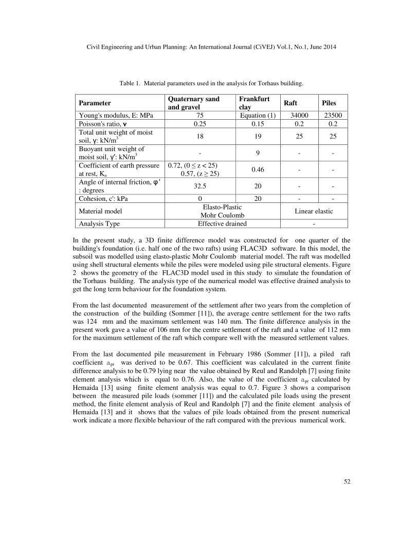
Table 1. Material parameters used in the analysis for Torhaus building.
Parameter Quaternary sand
and gravel
Frankfurt
clay Raft Piles
Young's modulus, E: MPa 75 Equation (1) 34000 23500
Poisson's ratio, νννν 0.25 0.15 0.2 0.2
Total unit weight of moist
soil, γ: kN/m3
18 19 25 25
Buoyant unit weight of
moist soil, γ': kN/m3
- 9 - -
Coefficient of earth pressure
at rest, Ko
0.72, (0 ≤ z < 25)
0.57, (z ≥ 25) 0.46 - -
Angle of internal friction, φ'
: degrees 32.5 20 - -
Cohesion, c': kPa 0 20 - -
Material model Elasto-Plastic
Mohr Coulomb Linear elastic
Analysis Type Effective drained -
In the present study, a 3D finite difference model was constructed for one quarter of the
building's foundation (i.e. half one of the two rafts) using FLAC3D software. In this model, the
subsoil was modelled using elasto-plastic Mohr Coulomb material model. The raft was modelled
using shell structural elements while the piles were modeled using pile structural elements. Figure
2 shows the geometry of the FLAC3D model used in this study to simulate the foundation of
the Torhaus building. The analysis type of the numerical model was effective drained analysis to
get the long term behaviour for the foundation system.
From the last documented measurement of the settlement after two years from the completion of
the construction of the building (Sommer [11]), the average centre settlement for the two rafts
was 124 mm and the maximum settlement was 140 mm. The finite difference analysis in the
present work gave a value of 106 mm for the centre settlement of the raft and a value of 112 mm
for the maximum settlement of the raft which compare well with the measured settlement values.
From the last documented pile measurement in February 1986 (Sommer [11]), a piled raft
coefficient apr was derived to be 0.67. This coefficient was calculated in the current finite
difference analysis to be 0.79 lying near the value obtained by Reul and Randolph [7] using finite
element analysis which is equal to 0.76. Also, the value of the coefficient apr calculated by
Hemaida [13] using finite element analysis was equal to 0.7. Figure 3 shows a comparison
between the measured pile loads (sommer [11]) and the calculated pile loads using the present
method, the finite element analysis of Reul and Randolph [7] and the finite element analysis of
Hemaida [13] and it shows that the values of pile loads obtained from the present numerical
work indicate a more flexible behaviour of the raft compared with the previous numerical work.

Civil Engineering and Urban Planning: An International Journal (CiVEJ) Vol.1, No.1, June 2014
53
Figure 2. Geometry of the FLAC3D model for the foundation of the Torhaus building: (a) finite difference
grid representing the soil; (b) shell and pile structural elements representing the raft and the piles
Figure 3. Comparison between measured and calculated pile loads for the piled raft foundation of the
Torhaus building

Civil Engineering and Urban Planning: An International Journal (CiVEJ) Vol.1, No.1, June 2014
54
4. PARAMETRIC STUDY
A comprehensive parametric study was performed to study the behaviour of piled raft foundation
founded on different subsoil conditions and using variable pile configurations and lengths under
a square hypothetical raft. The pile configurations involved three different distributions of the
piles over the raft area which are: uniform, concentrated at raft edges and concentrated at central
part of the raft. The number of piles ranged from 64 to 121 piles. The piles’ lengths used in the
study were: 12, 16 and 20 m. Table 2.0 shows the cases studied in the parametric study, where
each combination between a pile configuration and a specific pile length was tested upon the
three given soil profiles.
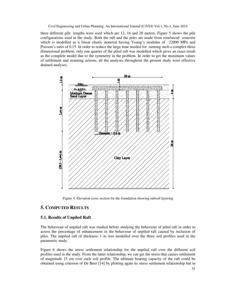
Three soil profiles are used in the parametric study. Each soil profile is 30 m in depth consisting
of two layers as follows: (1) Top medium dense sand layer having thickness equal to 4 m. The
properties of this layer are the same for the three soil profiles. (2) Bottom clay layer of thickness
equal to 26 m. For this layer, three different clay types were used which are: soft clay, medium
clay, stiff clay. Each soil profile is named according to the clay type composing its bottom layer
(e.g. Soft clay profile means that the top soil layer is medium dense sand and the bottom soil layer
is soft clay). Both the foundation level of the raft and the ground water table are located at the
same level of 1.5 m below the natural ground level as shown in Figure 4. Table 3. presents the
soil parameters used in the analyses.
Table 2. Program of the parametric study.
Pile Configuration Pile Length (m) Soil Profile
Unpiled NA Soft clay Medium clay Stiff clay
A 12 16 20 Soft clay Medium clay Stiff clay
B 12 16 20 Soft clay Medium clay Stiff clay
C 12 16 20 Soft clay Medium clay Stiff clay
D 12 16 20 Soft clay Medium clay Stiff clay
R 12 16 20 Soft clay Medium clay Stiff clay
Table 3. Material parameters of the soil types used in the parametric study.
Parameter
Medium
dense
sand
Soft clay Medium
clay Stiff clay
Young's modulus, E (MPa) 35 8 15 25
Poisson's ratio, νννν 0.3 0.45 0.45 0.45
Total unit weight of moist soil, γ (kN/m3) 18 18 18 18.5
Coefficient of earth pressure at rest, Ko 0.46 0.6 0.5 0.75
Angle of internal friction, φ' (degrees) 33 30 30 25
Cohesion, c' (kPa) 0 10 0.1 15
Material model Mohr-Coulomb
Analysis Type Effective drained
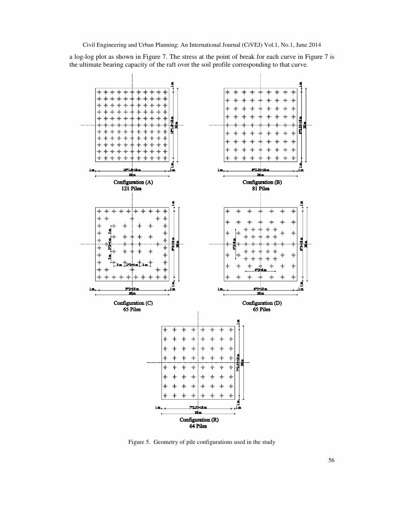
The raft used in the parametric study is square in plan with dimensions of 20 * 20 meters and
thickness equals 1 meter which is kept constant throughout the study. Five pile configurations
were used with number of piles ranging between 64 and 121 circular piles involving three ways
for distributing the piles upon the raft surface area: uniform, concentrated at raft edges and
concentrated at central part of the raft. The pile diameter used was 0.60 meter for all cases in the
study. In order to examine the effect of variation in pile length upon the foundation behaviour,
Civil Engineering and Urban Planning: An International Journal (CiVEJ) Vol.1, No.1, June 2014
55
three different pile lengths were used which are 12, 16 and 20 meters. Figure 5 shows the pile
configurations used in the study. Both the raft and the piles are made from reinforced concrete
which is modelled as a linear elastic material having Young’s modulus of 22000 MPa and
Poisson’s ratio of 0.15. In order to reduce the large time needed for running such a complex three
dimensional problem, only one quarter of the piled raft was modelled which gives an exact result
as the complete model due to the symmetry in the problem. In order to get the maximum values
of settlement and straining actions, all the analyses throughout the present study were effective
drained analyses.
Figure 4. Elevation cross section for the foundation showing subsoil layering
5. COMPUTED RESULTS
5.1. Results of Unpiled Raft
The behaviour of unpiled raft was studied before studying the behaviour of piled raft in order to
assess the percentage of enhancement in the behaviour of unpiled raft caused by inclusion of
piles. The unpiled raft of thickness 1 m was modelled over the three soil profiles used in the
parametric study.
Figure 6 shows the stress settlement relationship for the unpiled raft over the different soil
profiles used in the study. From the latter relationship, we can get the stress that causes settlement
of magnitude 15 cm over each soil profile. The ultimate bearing capacity of the raft could be
obtained using criterion of De Beer [14] by plotting again its stress settlement relationship but in
Civil Engineering and Urban Planning: An International Journal (CiVEJ) Vol.1, No.1, June 2014
56
a log-log plot as shown in Figure 7. The stress at the point of break for each curve in Figure 7 is
the ultimate bearing capacity of the raft over the soil profile corresponding to that curve.
Figure 5. Geometry of pile configurations used in the study

Civil Engineering and Urban Planning: An International Journal (CiVEJ) Vol.1, No.1, June 2014
57
Figure 6. Stress settlement relationship of unpiled raft over different soil profiles
Figure 7. Log-log plot for stress settlement relationship of unpiled raft to estimate its ultimate bearing
capacity
5.2. Results of Piled Raft
The effect of variation of piles number, configuration and length on the stress average settlement
behavior and the stress differential settlement on pile raft was discussed in the following sections.

Civil Engineering and Urban Planning: An International Journal (CiVEJ) Vol.1, No.1, June 2014
58
Figure 8 shows the patterns of the grid for the different pile configurations and the shell
structural elements representing the raft and the pile structural elements.
Figure 8. Finite difference grid for the different pile configurations
5.2.1. Stress – average settlement behaviour of piled raft
In order to study the effect of variation of piles’ number, configuration and length on the stress –
average settlement behaviour of piled raft for the different soil profiles, the average settlement
was plotted versus the stress as shown in Figure 9 (the stress plotted in the figure is the vertical
stress applied over the raft surface). The behaviour of unpiled raft was plotted for each case on
the same figure for purpose of comparison with the corresponding behaviour of the piled raft. The
stress causing 15 cm settlement will be referred to as the “piled raft working stress” as it is the
stress corresponding to the allowable settlement for the foundation. Figures 10 through Figure 12
present the effect of piles’ number, configuration and length on the piled raft working stress for
the different soil profiles. Also, the unpiled raft working stress corresponding to 15 cm settlement
was plotted to show the percentage of improvement in the working stress when piles are added to
the unpiled raft. From the above mentioned figures we may notice the following:
� The increase in number of piles does not make a significant reduction in the average
settlement of the piled raft. Consequently, the piled raft working stress is not significantly
affected by the increase in number of piles. The ratio of the working stress of the pile

Civil Engineering and Urban Planning: An International Journal (CiVEJ) Vol.1, No.1, June 2014
59
configuration with maximum number of piles (configuration (A)) and that of the pile
configuration with minimum number of piles (configuration (R)) ranged between 1.05 and
1.17 for the piles’ lengths and soil profiles used in the study, while the maximum number of
piles was about 1.89 times the minimum number of piles. The above mentioned ratio has its
maximum values for the stiff clay soil profile and has its minimum values for the soft clay
soil profile.
� The increase in pile length effectively reduces the piled raft average settlement and in turns
significantly increases its working stress. The percentage of increase in the working stress
due to the increase in pile length becomes higher when the stiffness of the clay layer in the
soil profiles decreases, which means that soft clay soil profile has the largest percentage of
increase in the working stress due to the increase in pile length.
Although the three pile configurations named (C), (D) and (R) have almost equal number of piles
(65 for (C) and (D); 64 for (R)), but they have different stress-average settlement response. The
percentage of difference in the value of working stress for the three configurations ranged
between less than 1 % up to 14.5 %. The stiffness of configuration (R) is more than that of
configurations (C) and (D) because the uniform distribution of piles in configuration (R) made the
pile spacing kept constant at a value of 2.57 m, while in configurations (C) and (D) most of the
piles (the piles at area of concentration) are spaced at a value closer than 2.57 m. The relatively
narrow spacing for piles at the edges for configuration (C) and at the centre for configuration (D)
increases the negative group action which reduces their stiffness compared to that of
configuration (R). Also, the concentration of piles at the edges in configuration (C) causes a
lesser negative group action than the concentration of piles at the centre in configuration (D)
because piles at the edges are by nature stiffer than piles at the centre. This is attributed to the
block deformation of the pile group which makes differential settlement relative to the
surrounding soil for edge pile more than that for a centre pile. Hence, the pile shaft load for an
edge pile will be greater than that for a centre pile while base loads are the same (Reul and
Randolph [7]).
Figure 9. Stress-average settlement relationship for piled raft over soft clay soil profile (pile length = 12 m)

Civil Engineering and Urban Planning: An International Journal (CiVEJ) Vol.1, No.1, June 2014
60
Figure 10. Effect of piles’ number, configuration and length on piled raft working stress for soft clay soil
profile
Figure 11. Effect of piles’ number, configuration and length on piled raft working stress for medium clay
soil profile

Civil Engineering and Urban Planning: An International Journal (CiVEJ) Vol.1, No.1, June 2014
61
Figure 12. Effect of piles’ number, configuration and length on piled raft working stress for stiff clay soil
profile
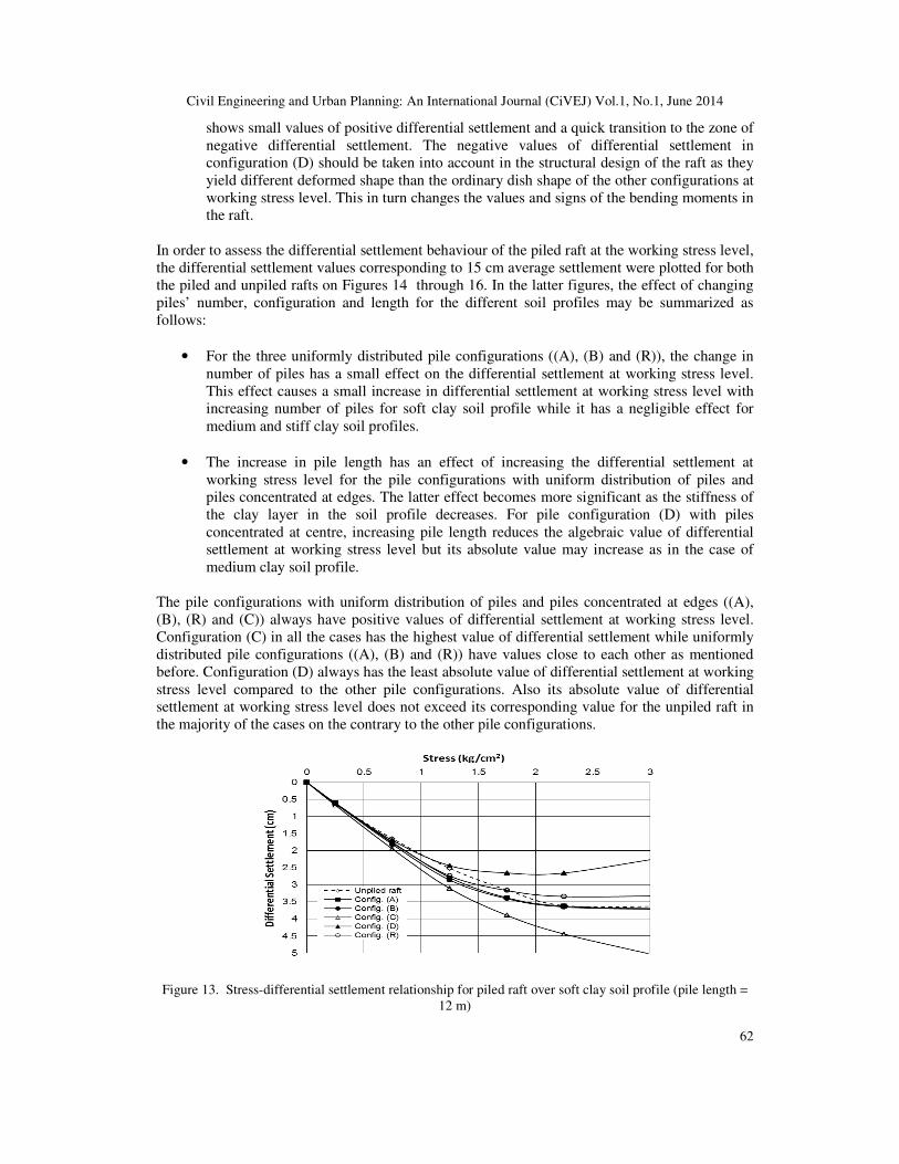
5.2.2. Stress – differential settlement behaviour of piled raft
The differential settlement is an important issue in studying the behaviour of piled raft foundation
as it has a great effect on the safety and serviceability of the superstructure. In the present study,
the differential settlement is considered to be the difference between the settlement of the raft
centre and that of the raft corner. The differential settlement of the piled raft was plotted versus
the stress as shown in Figure 13. Also the differential settlement of the unpiled raft was plotted
for each case on the same figure. From the plotted stress-differential settlement curves we may
notice the following:
• The increase in number of piles has a very small effect on the differential settlement. This
can be proved by comparing the stress-differential settlement curves of the three
uniformly distributed pile configurations ((A), (B) and (R)), which are almost identical or
very near to each other.
• The change of the distribution of piles upon the raft area has the maximum effect on the
stress-differential settlement response of the piled raft. The pile configurations with
uniform distribution of piles named (A), (B) and (R) take the same trend and their curves
are near to the unpiled raft curve especially at the zone of positive differential settlement.
It is noted that as the stiffness of the clay layer in the soil profile increases, the behaviour
of uniformly distributed pile configurations diverges away from the behaviour of the
unpiled raft. The response of configuration (C) with piles concentrated at the edges shows
that it always has positive values of differential settlement even at higher stress levels and
its differential settlement tends to increase by increasing the stress level. This behaviour
of configuration (C) is due to the concentration of piles at edges which makes the
settlement of the raft centre always greater than that of the raft corner. On the contrary,
we notice that the behaviour of configuration (D) with piles concentrated at the centre
Civil Engineering and Urban Planning: An International Journal (CiVEJ) Vol.1, No.1, June 2014
62
shows small values of positive differential settlement and a quick transition to the zone of
negative differential settlement. The negative values of differential settlement in
configuration (D) should be taken into account in the structural design of the raft as they
yield different deformed shape than the ordinary dish shape of the other configurations at
working stress level. This in turn changes the values and signs of the bending moments in
the raft.
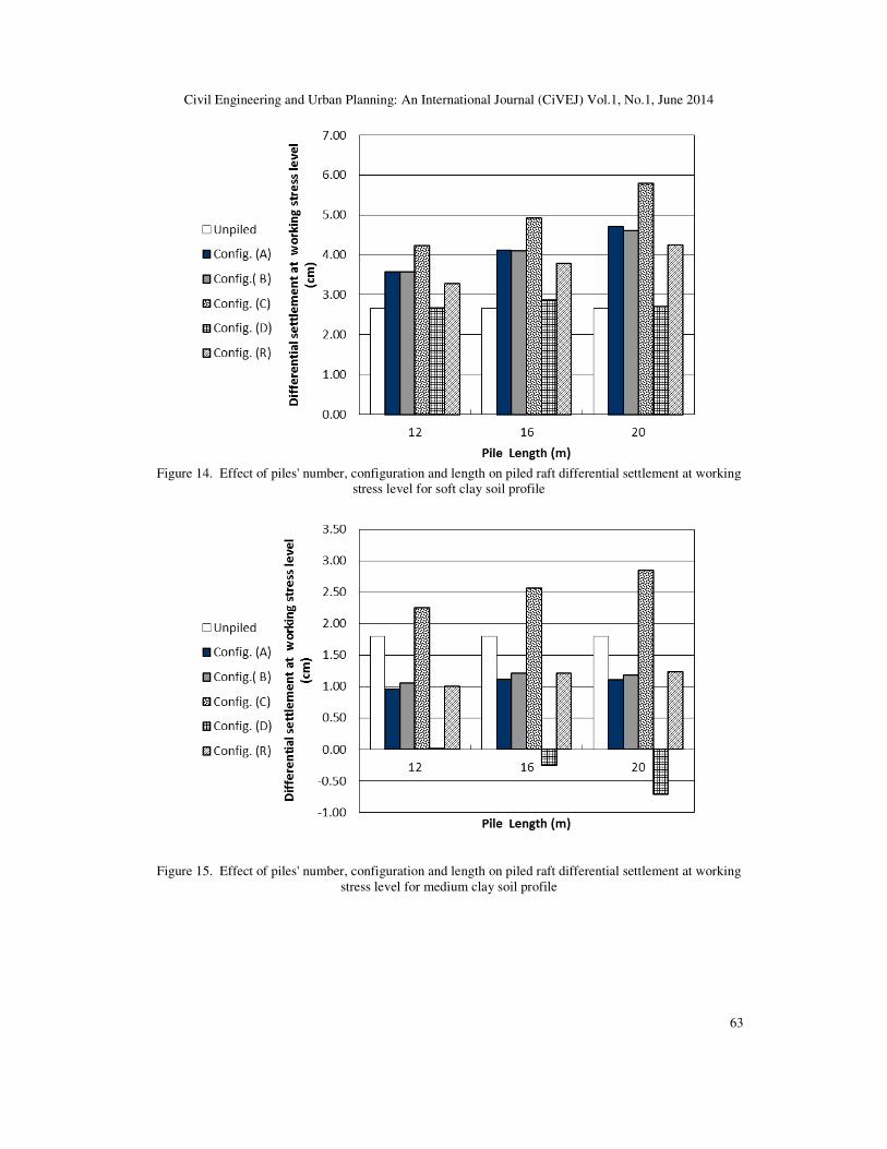
In order to assess the differential settlement behaviour of the piled raft at the working stress level,
the differential settlement values corresponding to 15 cm average settlement were plotted for both
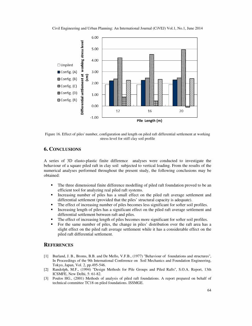
the piled and unpiled rafts on Figures 14 through 16. In the latter figures, the effect of changing
piles’ number, configuration and length for the different soil profiles may be summarized as
follows:
• For the three uniformly distributed pile configurations ((A), (B) and (R)), the change in
number of piles has a small effect on the differential settlement at working stress level.
This effect causes a small increase in differential settlement at working stress level with
increasing number of piles for soft clay soil profile while it has a negligible effect for
medium and stiff clay soil profiles.
• The increase in pile length has an effect of increasing the differential settlement at
working stress level for the pile configurations with uniform distribution of piles and
piles concentrated at edges. The latter effect becomes more significant as the stiffness of
the clay layer in the soil profile decreases. For pile configuration (D) with piles
concentrated at centre, increasing pile length reduces the algebraic value of differential
settlement at working stress level but its absolute value may increase as in the case of
medium clay soil profile.
The pile configurations with uniform distribution of piles and piles concentrated at edges ((A),
(B), (R) and (C)) always have positive values of differential settlement at working stress level.
Configuration (C) in all the cases has the highest value of differential settlement while uniformly
distributed pile configurations ((A), (B) and (R)) have values close to each other as mentioned
before. Configuration (D) always has the least absolute value of differential settlement at working
stress level compared to the other pile configurations. Also its absolute value of differential
settlement at working stress level does not exceed its corresponding value for the unpiled raft in
the majority of the cases on the contrary to the other pile configurations.
Figure 13. Stress-differential settlement relationship for piled raft over soft clay soil profile (pile length =
12 m)
Civil Engineering and Urban Planning: An International Journal (CiVEJ) Vol.1, No.1, June 2014
63
Figure 14. Effect of piles' number, configuration and length on piled raft differential settlement at working
stress level for soft clay soil profile
Figure 15. Effect of piles' number, configuration and length on piled raft differential settlement at working
stress level for medium clay soil profile
Civil Engineering and Urban Planning: An International Journal (CiVEJ) Vol.1, No.1, June 2014
64
Figure 16. Effect of piles' number, configuration and length on piled raft differential settlement at working
stress level for stiff clay soil profile
6. CONCLUSIONS
A series of 3D elasto-plastic finite difference analyses were conducted to investigate the
behaviour of a square piled raft in clay soil subjected to vertical loading. From the results of the
numerical analyses performed throughout the present study, the following conclusions may be
obtained:
� The three dimensional finite difference modelling of piled raft foundation proved to be an
efficient tool for analyzing real piled raft systems.
� Increasing number of piles has a small effect on the piled raft average settlement and
differential settlement (provided that the piles’ structural capacity is adequate).
� The effect of increasing number of piles becomes less significant for softer soil profiles.
� Increasing length of piles has a significant effect on the piled raft average settlement and
differential settlement between raft and piles.
� The effect of increasing length of piles becomes more significant for softer soil profiles.
� For the same number of piles, the change in piles’ distribution over the raft area has a
slight effect on the piled raft average settlement while it has a considerable effect on the
piled raft differential settlement.
REFERENCES
[1] Burland, J. B., Broms, B.B. and De Mello, V.F.B., (1977) ''Behaviour of foundations and structures'',
In Proceedings of the 9th International Conference on Soil Mechanics and Foundation Engineering,
Tokyo, Japan, Vol. 2, pp.495-546.
[2] Randolph, M.F., (1994) ''Design Methods for Pile Groups and Piled Rafts'', S.O.A. Report, 13th
ICSMFE, New Delhi, 5: 61-82.
[3] Poulos HG., (2001) Methods of analysis of piled raft foundations. A report prepared on behalf of
technical committee TC18 on piled foundations. ISSMGE.
Civil Engineering and Urban Planning: An International Journal (CiVEJ) Vol.1, No.1, June 2014
65
[4] De Sanctis L, Mandolini A., (2003) On the ultimate vertical load of piled rafts on the soft clay soils.
In: Proceedings of 4th international geotechnical seminar on deep foundation on bored and auger
piles. Ghent: Millpress; p. 379–86.
[5] de Sanctis L, Mandolini A., (2006) Bearing capacity of piled rafts on soft clay soils. J Geotech
Geoenviron Eng (ASCE);132(12):1600–10.
[6] Katzenbach R, Arslan U, Moormann C., (1998) Design and safety concept for piled raft foundations.
In: Proceedings of 3th international geotechnical seminar on deep foundation on bored and auger
piles. Ghent: Balkema; p. 439–48.
[7] Reul O, Randolph MF., (2003) Piled rafts in overconsolidated clay-comparison of in situ
measurements and numerical analyses. Geotechnique; 53(3):301–15.
[8] Reul O, Randolph MF., (2004) Design strategies for piled rafts subjected to nonuniform vertical
loading. J Geotech Geoenviron Eng (ASCE);130(1):1–13.
[9] Itasca Consulting Group. FLAC3D, fast lagrangian analysis of continua. Minneapolis: User’s manual,
2005.
[10] Sommer, H., Wittmann, P. and Ripper, P., (1985) "Piled raft foundation of a tall building in Frankfurt
clay", Proceedings of 11th ICSMFE, Sanfransisco, Vol. 4, pp 2253-2257.
[11] Sommer, H., (1991) ''Entwicklung der Hochhausgründungen in Frankfurt/Main'', Festkolloquium 20
Jahre Grundbauinstitut Prof. Dr.-Ing. J. Sommer und Partner, pp. 47- 62, Germany.
[12] Reul, O., (2000) ''In-situ measurements and numerical studies on the bearing behaviour of piled rafts'',
PhD thesis, Darmstadt University of Technology, Germany (in German).
[13] Hemaida, A.A., (2007) ''Numerical Modelling of Vertically Loaded Piled Raft Foundation'', Ph.D.
thesis, Cairo University, Egypt.
[14] De Beer, E. E., (1967) ''Proefondervindelijke bijdrage tot de studie van het gransdraagvermogen van
zand onder funderingen opstaal; Bepaling von der vormfactor sb'', Annales des Travaux Publics de
Belgique, 68, No. 6, pp 481-506.