experimental research and finite element analysis on...
TRANSCRIPT
Contents lists available at ScienceDirect
Engineering Structures
journal homepage: www.elsevier.com/locate/engstruct
Experimental research and finite element analysis on seismic behavior ofCFRP-strengthened seismic-damaged composite steel-concrete framecolumns
Sheng Penga, Chengxiang Xua,⁎, Mengxiao Lub, Jianming Yanga
a Department of Civil Engineering, School of Urban Construction, Wuhan University of Science and Technology, Wuhan 430065, PR Chinab School of Urban Construction, Yangtze University, Jingzhou 434023, PR China
A R T I C L E I N F O
Keywords:Carbon fiber reinforced polymer strengtheningComposite steel–concrete frame columnsSeismic damageFinite element analysisSeismic behavior
A B S T R A C T
Four composite steel–concrete frame columns were constructed to investigate the seismic performance ofseismic-damaged composite steel–concrete frame columns strengthened with carbon fiber reinforced polymer.The test consisted of pre-damage loading, rehabilitation with carbon fiber reinforced polymer and destructiontests under lateral cyclic loading. The effectiveness of strengthening seismic-damaged columns with carbon fiberreinforced polymer and the strengthening effect on different degrees of seismic damage were studied. Also, basedon the test data, various parameters were obtained, including the hysteretic loops, skeleton curves, axial com-pression ratio, number of pasted layers of carbon fiber reinforced polymer, ductility, dissipative ability, ultimatestrength, stiffness degradation, etc. The results revealed that the failure mode of all the columns was bendingfailure. The study indicates that the rehabilitated columns can reach or even exceed the level of their originalseismic performance before seismic damage up to a certain extent of damage level. Composite steel–concreteframe columns strengthened with carbon fiber reinforced polymer sheets were simulated using the finite elementanalysis software ABAQUS. The comparison of the results of the conducted analytical study with the experi-mental results revealed that they are basically consistent with each other.
1. Introduction
The frame column structure composed of sections of steel-reinforcedconcrete has been widely used in super-high building structures andlarge span structures due to its high load-carrying capacity, goodseismic performance, and other advantages [1]. Seismic evaluation andstrengthening of composite steel-concrete structures are not mentionedin guidelines publications, such as “Standard for Seismic Appraisal ofBuildings” (GB50023-2009),“Technical specification for seismicstrengthening of buildings” (JGJ116-2009) and “Technical guidelinesfor seismic evaluation and strengthening of post-earthquake buildings”.In practical engineering, the carbon fiber sheet has received consider-able attention due to its high-strength, light-weight, high corrosionresistance, and ease of fabrication, etc. This effective strengtheningmethod using composite steel-concrete structures has become more andmore widely used in the United States, Canada, Japan, and recently,Europe. In China, the research and application of carbon fiber re-inforced polymer (CFRP) for strengthening reinforced concrete struc-tures began in 1997.
Several studies have been conducted on the seismic performance
and behavior under reinforced concrete [2–4] and composite steel–-concrete columns [5–7], steel fiber reinforced concrete (SFRC) [8] andconcrete-encased composite structures of concrete frame and steel–-concrete composite columns, as well as the behavior under ultra-highperformance fiber reinforced concrete (UHPFRC) [9–11] and numericalsimulation methods [12,13]. The design calculation theory and con-struction method are given in the building codes, such as ACI 318-05code [14], JGJ 138-2001 specifications [15], AIJ-SRC standard [16]and the AISC Manual of Steel Construction [17].
In experimental research, these include, a study on seismic-damagedRC column, frame and beam–column joints strengthened with stainlesssteel wire mesh composite [18], CFRP [19], and epoxy resin injection[23–25], respectively. The method of CFRP-strengthened seismic-da-maged exterior joints in composite frame consisting of CFSST columnsand steel beams were proposed by Xu et al. [20]. A detailed in-vestigation on the assessment of the performance of new material waspresented by Zhang [21], and the theoretical development of the me-chanical properties of new material with the time was extensivelystudied by Wang [22]. According to published experimental studies, RCstructures could be strengthened with new material [21,22]. Idris and
https://doi.org/10.1016/j.engstruct.2017.10.065Received 22 March 2017; Received in revised form 24 October 2017; Accepted 25 October 2017
⁎ Corresponding author.E-mail address: [email protected] (C. Xu).
Engineering Structures 155 (2018) 50–60
0141-0296/ © 2017 Elsevier Ltd. All rights reserved.
MARK

Ozbakkaloglu studied the seismic behavior of the seismic-damagedhigh-strength concrete-filled tube columns strengthened with FRPsubjected to constant axial load and cyclic lateral loads [26–28], andsummarized the Confinement model of FRP-confined high-strengthconcrete [32,33]. However, very few methods and experimental studiesare available on seismic-damaged composite steel-concrete framecolumn structure. There are rarely reports on seismic performance andfailure mechanism of seismic-damaged composite steel-concrete framecolumn structures reinforced with strengthening materials. Here,seismic-damaged composite steel-concrete column structure strength-ened with CFRP are put forward.
In this study, cyclic loading tests were performed on four compositesteel-concrete columns to investigate the effect of the strengthening ofseismic-damaged composite steel-concrete with CFRP on the perfor-mance of frame columns. The tests included horizontal load testing,horizontal displacement testing and recording of the load-displacementhysteresis loops of the specimens. The mechanical process, failuremode, hysteretic characteristics, skeleton curves, ductility and energydissipation capacity were taken into account. The simulation calcula-tion was carried out using the ABAQUS software.
Simulation calculation and experimental results are compared toverify the rationality and the experimental results. The authors hope toprovide references for seismic-damaged composite steel-concrete framecolumn structure strengthened with CFRP.
2. Experimental program
2.1. Test specimens
Four composite steel-concrete frame columns, with different de-grees of post-earthquake seismic damage, were designed for the tests,and numbered from SRC-1 to SRC-4.
The data shown in Table 1 indicate that specimens SRC-1, SRC-2,SRC-3, SRC-4 are under the same axial compression ratio, and have thesame shear span ratio and concrete strength grade. Accordingly, theycan be considered to have the same degree of damage and strength-ening level. Based on the same considerations, specimens SRC-2, SRC-3and SRC-4 are also considered to have the same number of strength-ening CFRP layers [23]. Besides, the composite steel-concrete framecolumns are short columns.
Although specimen SRC-1 has not been strengthened and SRC-2 hasbeen strengthened, both SRC-1 and SRC-2 specimens are undamaged. Adisplacement angle of 1/100 was used to simulate the moderate da-mage of specimen SRC-3, while a displacement angle of 1/50 was usedto simulate the severe damage of specimen SRC-4. The test specimenshad a rectangle cross section of 200mm×270mm and the coverthickness of the concrete specimens was kept at 25mm. The cross-section reinforcement ratio of the specimens is 1.6% and the stirrupratio is 0.68%, while the steel ratio of the specimens is 4.84%. To en-sure the same quality of concrete the C40 commercial concrete wasused, pouring from the same batch, with 28 days of maintenance.
The properties of the materials were controlled by the materialcategories and material specifications given in Table 2. The config-urations of a specimen cross-section and the diagram of strengtheningby CFRP are shown in Fig. 1. Specifically, the arrangement of the straingauges on the specimens is shown in Fig. 1a. The strains of the
longitudinal (S1∼ S3) section of steel were measured by the straingauges. The composite steel-concrete column base was strengthenedwith CFRP. The CFRP was pasted in the direction perpendicular to theaxis of the column using the circular uniform packing method. Thelayer number is two and the lap length is 150mm. while thestrengthening height is 500mm.
2.2. Materials properties
The properties of the materials, such as concrete, steel, bar CFRPand mucilage are listed in Table 2.
2.3. Test device and loading system
The columns were constructed and tested at the Civil EngineeringExperiment Center of Yangtze University. All specimens were testedafter 28 days of maintenance.
Premixed concrete was used. To determine the average concretecompressive strength, three cylinders were tested for each specimen.The measured compressive strength of concrete was 39.6 MPa. The test,performed under lateral cyclic loading, consisted of pre-damageloading, rehabilitation with CFRP and destruction tests.
The test set-up and loading system are shown in Fig. 2(b). The lat-eral load was applied by a servo-controlled hydraulic actuator at theupper column end, using a displacement-controlled tester at a speed of10mm/min. A hinge support was used at the bottom of each column ofthe axial load reaction frame, allowing the reaction frame to rotate [5].The specimens can be rigidly anchored to the ground through theground beam which was placed at the bottom of the specimens. Theupper end loading scheme was adopted to simulate the P − Δ effectcaused by the applied axial compressive load acting on the lateraldisplacement of the columns. The axial compressive load was appliedby a hydraulic jack installed at the upper end of column and it remainedconstant. The tests of the loading system followed the JGJ101-96guidelines [29].
The columns were laterally subjected to a predetermined cyclicdisplacement history as indicated in Fig. 2(a), which shows that thepeak displacements were increased in multiples of the yielding dis-placement. The load control occurred before the specimens yielded, andthe displacement control occurred after the specimens yielded.
The specimens were subjected to one cycle before yielding and threesuccessive cycles after yielding. The experiment was stopped when theload dropped below 85% of the ultimate load, or the specimens wereunable to bear the axial force.
2.4. Reinforcement of specimens
The reinforcement of the specimens was performed following theGB/CECS146-2003 guidelines. To prevent the transfer of plastic hingeduring the tests, the reinforcement height should be higher than theplastic hinge, at the bottom of the columns.
Before the reinforcement, the surface of the concrete should beground until its aggregate was exposed [29] and the fillet radius pro-cessed to 20mm at the bottom as indicated in Fig. 1(b).
Table 1Parameters of specimens.
Specimen Damage degree Axial compression ratio Shear span ratio Concrete strength grade CFRP layer number Strengthened level
SRC-1 Undamaged 0.32 1.5 C40 – NoSRC-2 Undamaged 0.32 1.5 C40 2 yesSRC-3 Moderate damaged 0.32 1.5 C40 2 yesSRC-4 Severe damaged 0.32 1.5 C40 2 yes
S. Peng et al. Engineering Structures 155 (2018) 50–60
51

3. Experimental results and analysis
3.1. Experimental phenomena and failure mode
The test consisted of two parts: pre-yielding and post-yielding.Before yielding, the specimens were in the elastic stage, and the
value of the residual deformation was small. The deformation recoveredwhen the specimen was unloaded. When the horizontal displacementincreased to about 3.6 mm, the first crack appeared on the tensile sideat the column bottom end. When the horizontal displacement increasedto± 9mm, the longitudinal reinforcement and steel flange yielded onthe tensile side, and oblique cracks developed at the column bottomend.
After yielding, the horizontal displacement increased to±18mm,existing cracks continued to develop and new cracks appeared at thecolumn bottom end. With the increase of the number of cracks and theirwidth, the specimens of bearing capacity significantly degraded andsome apparent X-shaped cross inclined cracks were observed. When thehorizontal displacement increased to± 27mm, the concrete-flake-offextended at the column bottom zone. With the circle of reverse un-loading-loading, the concrete-flake-off position moved towards themiddle of the column. When the horizontal displacement increasedto± 36mm, the cracks transfixed and the concrete-flake-off appeared,and the stirrups and longitudinal reinforcements were exposed andbent. When the horizontal displacement increased to about± 45mm,the stirrups and part of longitudinal reinforcements were damaged.Then the bearing capacity of the specimens dropped below 85% and thetesting stopped.
At the end of the test, the lateral load dropped rapidly and the
specimens lost the bearing capacity. However, the core concrete hadlittle damage due to the restraint of the structural steel located in thecenter zone of the cross section. Flexural failure of the specimens oc-curred in the plastic hinge zone. The failure mode of specimen SRC-1 isshown in Fig. 3(a) and the failure mode of the limit state at the bottomend of the columns of the different seismic-damaged CFRP-strength-ened specimens, including SRC-2, SRC-3 and SRC-4, are presented inFig. 3(b)–(d). When the horizontal displacement is shorter than±18mm, the CFRP did not experience obvious change, and sporadic brittlecrack occurred at weak positions in the CFRP viscose. When the hor-izontal displacement increased to 18mm, folding appeared on theCFRP. Specifically, there were no cracks in the SRC-2 specimen, smallhorizontal cracks occurred in the SRC-3 specimen on the tensile side atthe bottom end of the column and horizontal cracks occurred in theSRC-4 specimen on the tensile side at the bottom end of the columnwith clear crack voice at the weak positions in the CFRP viscose.
When the horizontal displacement increased to± 27mm, hor-izontal cracks began to appear in the CFRP at the bottom end of thecolumn of specimen SRC-2, and existing cracks continued to develop atbottom end of the column of specimen SRC-3 and specimen SRC-4 hadnew horizontal cracks in the CFRP on its tensile side. Horizontal crackscontinued to spread and close due to the cyclic loading and the crackwidth progressively grew.
When the horizontal displacement increased to± 36mm, the ex-isting cracks continued to develop in the CFRP at the bottom end of thecolumn, and the number of new cracks and their width continuouslyincreased and formed the horizontal transfixion fracture. During cyclicloading, large horizontal transfixion fracture appeared at the bottomend of the column when the horizontal displacement increased to about
Table 2Materials properties.
Material Specification Elastic modulus Es/MPa Tensile strengthfy/MPa
Compressive strength fu/MPa Yield strengthfy/MPa
Ultimate strengthfu/MPa
Concrete 150mm length cube – – 39.6 – –I16 steel Q235B 2.01× 10⁵ – – 264.5 405.8Longitudinal bar HRB400 2.05× 10⁵ – – 375.7 515.6Stirrup HPB300 2.10× 10⁵ – – 312.4 443.1CFRP CJ300-I 2.50× 10⁵ 3560 – – –Mucilage CFRP mucilage 2476 42 – – –
Crack repair mucilage 1563 30 – – –
(a) Specimen dimension and steel details
Note: dimensions are in mm (b) Strengthening of carbon fiber sheets at column bottom
Fig. 1. Specimen dimension and Strengthening.
S. Peng et al. Engineering Structures 155 (2018) 50–60
52

45mm. Concrete crushing appeared on the compressive side at thecolumn bottom end, and a drum curve appeared in the CFRP on thetension side at the bottom end of the column.
When the horizontal displacement increased to±54mm, the drumcurve continued to develop in the CFRP, and horizontal visible cracksappeared at the bottom end of the column of specimen SRC-4. Then, thelateral load dropped rapidly, the specimens lost their bearing capacity,and the testing stopped. However, the core concrete had little damagedue to the restraint of the structural steel located in the center zone ofthe cross section. When the horizontal displacement increased to±63mm during cyclic loading, the horizontal transfixion fracture ap-peared at the bottom end if the column of specimens SRC-2 and SRC-3.
Then, the bearing capacity of the specimens dropped below 85%and the testing stopped.
3.2. Hysteretic curve
The hysteretic curve is a load-displacement relationship curve of the
specimen under cyclic loading. As shown in Fig. 4, the hysteretic curveis described by the measured lateral load and the displacement at thetop end of the column, which is an important representation of seismicperformance. The following observations can be made from the resultsshown in Fig. 4:
When a horizontal load was not bigger than the yield load, the curveslope changed slightly, and the unloading trajectory was approximatelylinear. Both the residual deformation and the hysteretic loop area be-came minimal. At the early stage of the test, the hysteretic loop areasincreased continuously when the horizontal displacement and numberof cycles increased. The specimen was destroyed rapidly with a poorductility.
The hysteretic behavior of the CFRP-strengthened specimen SRC-2,which had no seismic-damage, was better than that of specimen SRC-3,which had moderate seismic damage, and specimen SRC-4, which hadsevere seismic damage. In addition, the hysteretic behavior of theCFRP-strengthened specimen SRC-3, which had moderate seismic da-mage, was better than that of the CFRP-strengthened specimen SRC-4,
(a) Loading system for horizontal displacement
(b) Test set-up for cyclic loading test
Fig. 2. Test set-up and loading system.
(a) SRC-1 (b) SRC-2 (c) SRC-3 (d) SRC-4
Fig. 3. Failure modes of specimens.
S. Peng et al. Engineering Structures 155 (2018) 50–60
53

which had severe seismic damage. The hysteretic loop of specimensSRC-2 and SRC-3 had good stability when the horizontal displacementincreased to about 63mm. However, specimen SRC-4 failed when thehorizontal displacement reached to 54mm. The presence of cross tiehad a slight effect on the shape of the hysteretic curve of columns withT-shaped steel. There was slip between the CFRP and concrete influ-enced by the structural stability, and the bond between pre-damageconcrete and steel was not so strong and could easily lead to slip. In theend, the draw shrinkage of the hysteretic curve shape appeared in theCFRP-strengthened columns. The cross tie enhances the ultimatebearing capacity by confining the concrete and preventing buckling ofthe longitudinal bar.
Comparison of the hysteretic curves of specimens SRC-1 and SRC-2without any seismic damage reveals that the deformation and ductilityof specimen SRC-2 are better than those of the prototype contrastspecimen SRC-1. The manifestation of the seismic behavior of concreteof specimen SRC-2 was better due to its hysteretic curve roundness,deformability, energy dissipation capacity and longer loading cyclestime.
3.3. Skeleton curve
The skeleton curves of all specimens are shown in Fig.6. The resultsof the test of the characterization skeleton curves are shown in Table 3.
The skeleton curve reflects the characteristic of stress and de-formation at different stages of the test of the specimen, which is an
important parameter to determine the feature points in the restoringforce model. The cracking load defines the characteristics of the con-crete cracks in the specimens, and the corresponding concrete cracksare defined as cracking displacements.
The general yielding moment method, which made a tangent of theskeleton curve through the origin O, intersecting at A with the hor-izontal line through the peak load, is depicted in Fig.5. This methodalso made a vertical line through A, intersecting with the skeleton curve
(a) SRC-1 (b) SRC-2
(c) SRC-3 (d) SRC-4Fig. 4. Hysteretic loops of specimens.
Fig. 5. Definition of yield point and failure point.
S. Peng et al. Engineering Structures 155 (2018) 50–60
54
at B. When points A and B were connected and prolonged, point Cappeared. The horizontal line and skeleton curve intersected at D,which is the yield point.
Ductility factors and lateral loads are two of the most commonparameters used for the seismic evaluation of structural components. Inthe analysis of the skeleton curve, the positive loading direction wasdefined as when the wider flange of the inner structural steel wassubjected to tension, while negative loading direction was defined aswhen it was subjected to compression.
In Fig. 6(a)–(d), the envelopes of the lateral load-displacement re-sponses of all the tested specimens are compared to assess the effects of
the different strengthening situations and the degree of seismic damageon the ductility factors and lateral loads of the specimens. The experi-mental results for all columns are summarized in Table 3.
Py and Δy are the yielding load and corresponding displacement,respectively. Pm is the maximum applied lateral load and Δm is thecorresponding displacement. Pu is the failure load, which is defined as85% of the maximum lateral load. Pm and Δu are the correspondingfailure points, which are displaced. μ is the displacement ductilityfactor, calculated as Δu/Δy.
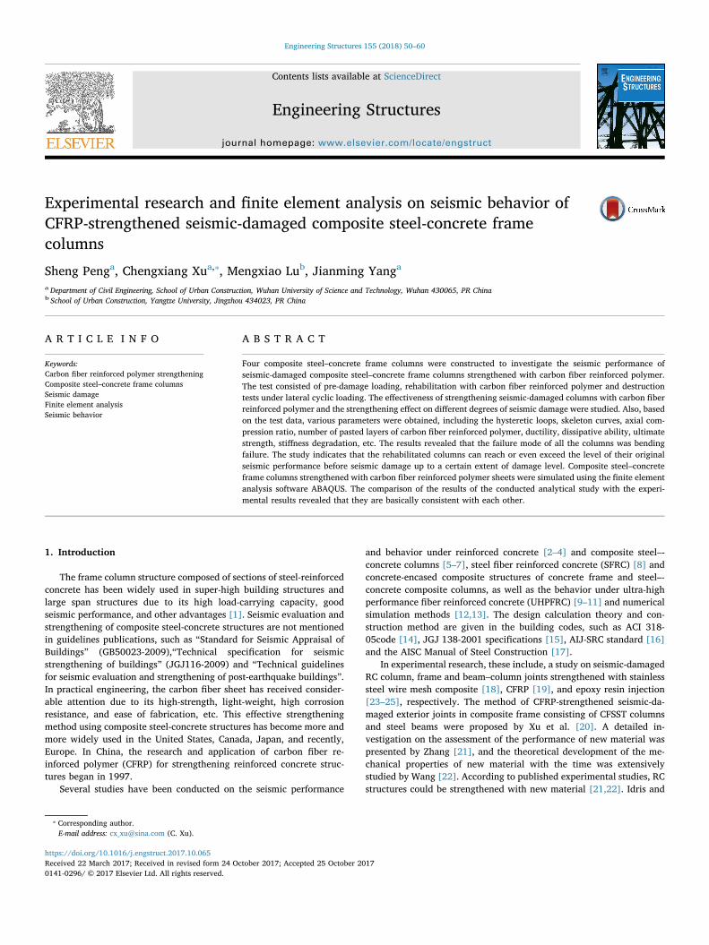
The skeleton curves shown in Fig.6 clearly show that the strength-ening section appeared after the yielding, and the descending stage of
(a) SRC-1 (b) SRC-2
(c) SRC-3 (d) SRC-4Fig. 6. Skeleton curves of specimens.
Table 3Characteristic points of skeleton curves.
Specimen Load direction Py/kN Δy/mm Pm/kN Δm/mm Pu/kN Δu/mm µ= Δu/Δy
SRC-1 Positive 74.89 16.45 129.50 26.80 110.10 47.67 2.89Negative 94.55 17.28 124.64 25.93 143.79 49.18 2.85
SRC-2 Positive 75.63 17.19 162.16 36.52 142.44 58.35 3.40Negative 95.24 18.21 148.36 35.44 134.62 61.12 3.36
SRC-3 Positive 76.35 17.33 147.55 34.41 116.92 57.36 3.31Negative 98.38 18.32 145.66 33.25 122.94 58.87 3.21
SRC-4 Positive 86.12 16.78 145.10 30.12 125.21 54.29 3.24Negative 82.06 17.32 143.79 29.83 106.44 52.48 3.03
S. Peng et al. Engineering Structures 155 (2018) 50–60
55
the CFRP-strengthened specimens appeared with gentle stability, whichshows that the deformability of the specimens is good. With the changeof the level of the earthquake damage, the strengthening of the speci-mens was only slightly influenced, while their ductility was clearlyinfluenced.
The experimental results of all specimens are summarized inTable 3, and the following conclusions were drawn.
The ultimate deformability of the specimens strengthened withCFRP becomes better.
The ductility coefficient of specimens SRC-1 and SRC-2, with thesame level of earthquake damage, increases in specimen SRC-2 from2.89 to 3.40, an increase of about 17.65%, when the specimen SRC-2 isstrengthened by CFRP.
The ductility coefficient decreases with the increase of the degree ofdamage. With the same degree of CFRP strengthening, the ductilitycoefficient of specimen SRC-2 is 3.40, and decreases to 3.31 in specimenSRC-3, and 3.24 in specimen SRC-4, which are decreases of about2.65% in SRC-2 and 4.71% in SRC-4, where the earthquake damagelevel of the specimen changes from undamaged to moderate damageand to severe damage, respectively.
The ductility coefficient of specimen SRC-1 is less than that ofspecimens SRC-3 and SRC-4, which indicates that the strengtheningwith CFRP can effectively increase the ductility of the specimens. Thisindicates that the strengthening with CFRP can enhance the bearingcapacity and ultimate displacement of the specimen. It mainly reflectsthe improvement of the mechanical behavior of the concrete, the de-formation failure of the concrete on the tensile side at the bottom end ofthe column constrained by CFRP, and the delay of the yielding of thelongitudinal reinforcement, which improves the ultimate bearing ca-pacity of the specimen.
The maximum bearing capacity of specimens SRC-1 is 129.50 and itincreases to 162.16 in SRC-2, 147.55 in SRC-3 and 145.50 in SRC-4,with rate of increase of about 36.27, 28.40 and 12.39% for SRC-2, SRC-3 and SRC-4, respectively. Meanwhile, the maximum displacement ofthe specimens is about 36.27, 28.40 and 12.39%, respectively, whichimproves the seismic behavior of the specimen.
The bearing capacity and displacement of the seismic-damagedCFRP-strengthened specimen can recover and even become better thanthe original specimen.
The characteristics of CFRP determine the strengthening and re-covery capacity of the specimen, as well as whether the increase of thedisplacement of the specimen is better than its bearing capacity.
3.4. Energy dissipation capacity
The energy dissipation capacity, shown in Table 3, is defined as the
dissipation capability of seismic energy in an earthquake, which is animportant parameter to assess the seismic behavior of a structure.
During an earthquake, good energy dissipation capacity is con-ducive to the safety and stability of structural components, avoidingsignificant damage on structures [23].
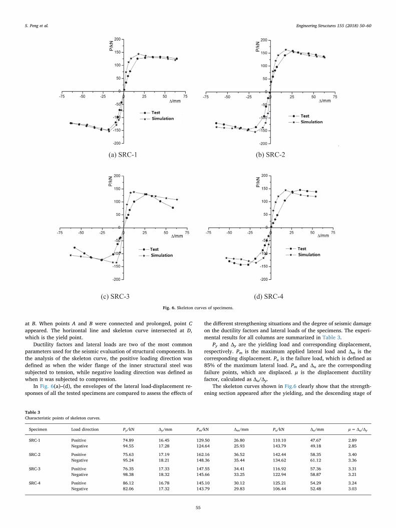
The analysis of the energy dissipation capacity uses equivalentviscous damping coefficient as in the following equation.
=+
h Aπ S S2 ·( )e
OBE ODFΔ Δ (1)
where A represents the area of a hysteretic loop, shown as the shadowarea in Fig. 8; (SΔOBE+ SΔODF) is the area of a triangle corresponding tothe maximum lateral load and the maximum horizontal displacementpoint of the hysteresis loop on the upper and lower sides. The hystereticloop area, surrounded with dashed lines, and the horizontal axis areshown in Fig.7.
The curves of the relationship between the equivalent viscousdamping coefficient and the displacement of the specimens with dif-ferent displacement levels under the first cyclic loading are shown inFig.8.
The curves depicted in Fig.8 reveal that there is a certain impact onthe energy dissipation capacity of the specimens strengthened withCFRP. The equivalent damping ratio of specimen SRC-1 is less than theequivalent damping ratio of specimens SRC-2, SRC-3 and SRC-4. Spe-cimen SRC-2 has the maximal equivalent damping ratio of all the spe-cimens.
With the increase of the displacement, the equivalent dampingcoefficient of all the specimens exhibits an upward trend. Clearly, theCFRP-strengthening has a great effect on the increase of equivalentdamping coefficient.
3.5. Stiffness degradation
The stiffness degradation is defined as the decrease of the stiffness ofthe structure in an earthquake, which is an important parameter toassess the seismic behavior of a structure.
Based on the experimental results the mean value of the secantstiffness for the ith cycle was evaluated using the following ratio:
=++
+ −
+ −KP P| | | |
|Δ | |Δ |im i m i
m i m i
, ,
, , (2)
where Ki is the secant stiffness, which shows that the stiffness of eachcycle can then be normalized with respect to the stiffness of the firstcycle. In theory, the elastic stage never undergoes stiffness degradation.
The relationships between the Ki ratio and the imposed displace-ment are plotted in Fig.9, which shows that as the horizontal dis-placement increases, the secant stiffness of the specimen graduallydecreases. The specimens underwent stiffness degradation at the early
Fig. 8. Equivalent damping ratio.
Fig. 7. Equivalent viscous damping coefficient he.
S. Peng et al. Engineering Structures 155 (2018) 50–60
56

stage of loading. The slope of the degradation curve is initially steeper,and then gradually tends to be moderate.
Stiffness degradation is more evident in the specimens strengthenedwith CFRP. Such a result indicated that increasing the level of theearthquake damage can improve the bearing capacity of the specimenswithin a certain range, but that will aggravate the stiffness degradationat the failure stage of loading.
The stiffness degradation of the specimens strengthened with CFRPis smaller than that of the original specimen, which indicated that CFRPcan effectively repair the damaged specimens and improve its seismicresistant capacity.
3.6. Ductility coefficient
Ductility is a macro behavior of the structure, which is mainly usedto characterize the deformation capacity of the specimens. The concreteof the compression side is not crushed due to the small bending mo-ment, which causes the slightly inclined cracks on the side of the ex-ternal concrete to rapidly develop upward along the steel flange.Ultimately, the failure of the bond with poor ductility occurred.
The ductility coefficient, shown in Table 3, is defined as ratio of thefailure displacement to yielding displacement of the column.
=μ ΔΔ
u
y (3)
With the same level of seismic damage, the ductility coefficient ofthe CFRP-strengthened specimen increases. The results indicated thatthe composite steel-concrete columns strengthened with CFRP can beused to delay ductility in the earthquake area. A comparison of the SRC-1 specimen with the CFRP-strengthened SRC-2 specimen revealed thatthe ductility of the latter is better.
With the same number of CFRP layers, the seismic damage is moresevere and the ductility coefficient of the pre-damage specimen issmaller. Different levels of seismic damage lead to different ductilitycoefficient of specimens SRC-2, SRC-3 and SRC-4. The influence of thelevel of seismic damage on the ductility of the specimen cannot be ig-nored. The ductility of the pre-damaged specimens which arestrengthened with CFRP decreases with the increase of the level ofseismic damage.
Comparison of specimen SRC-1 with specimen SCR-4 indicate thatthe ductility of the severely-damaged specimen strengthened with CFRPis better. The ductility of the severely-damaged specimen strengthened
Fig. 9. Stiffness degradation curves of specimens.
-1500
-1000
-500
0
500
1000
1500
-1500 -1000 -500 0 500 1000 1500
P/k
N
-1500
-1000
-500
0
500
1000
1500
-1500 -1000 -500 0 500 1000 1500
P/k
N
2-CRS1-CRS
-1500
-1000
-500
0
500
1000
1500
-1500 -1000 -500 0 500 1000 1500
P/k
N
-1500
-1000
-500
0
500
1000
1500
-1500 -1000 -500 0 500 1000 1500
P/k
N
4-CRS3-CRS
Strain( ×10^6) Strain( ×10^6)
Strain( ×10^6) Strain( ×10^6)
Fig. 10. Strains of section steel in the column of the bottom story.
S. Peng et al. Engineering Structures 155 (2018) 50–60
57

with CFRP increases significantly, and its ductility is better than that ofthe original specimen.
3.7. Strain analysis
The strains of the sections of steel in the composite steel-concreteframe columns at the bottom floor are shown in Fig. 10. The hystereticcharacteristics of the load-strain curve of the sections of steel are ob-vious. The average strain is less than 1500×106, and the residualstrain is smaller after unloading. The change of the strains of specimenSRC-2 to SRC-4 with the increase of the level of damage is remarkable.Compared with specimen SRC-1, the strain of the strengthened spe-cimen SRC-3 is larger, which shows that the deformation of the sectionof steel is a limited effect by the CFRP.
4. Finite element analysis
An analytical model is proposed for predicting the non-linear en-velope response of the strengthened columns. The model is based onrealistic material constitutive laws and accounts for the confinementeffect of the added CFRP on the strength of the column.
4.1. Material modeling
For further research on the seismic performance of the post-earth-quake composite steel-concrete frame, the column structure isstrengthened with CFRP. The nonlinear finite element softwareABAQUS was used to analyze the different tested specimens [33]. Thestiffness recovery index, ωc, which is defined as the stiffness recovery ofconcrete, is controlled under the cyclic loading [30].
When the load changed from tension to compression, as long as thecrack was closed, the compressive stiffness would be recovered(ωc= 1); when the load changed from compression to tension, as longas the crack appeared, the tensile stiffness could be recovered (ωc= 0)when the crack appeared [30].
The constitutive relation of concrete without reinforcement is thefollowing GB/T 50010-2010 “code for design of concrete structures”.There are several published studies on the FRP-confined concrete modeland the mechanical properties of this material have been studied ex-tensively. For further simulation and description the performance of theFRP-confined post-earthquake composite steel-concrete frame, thestress-strain model of the concrete confined with CFRP is proposedbased on the stress-strain model described by Yang et al. [31], given by:
⎜ ⎟ ⎜ ⎟= ⎡
⎣⎢
⎛⎝
⎞⎠
−⎛⎝
⎞⎠
⎤
⎦⎥ ⩽ ⩽σ f ε
εεε
ε ε2 0cpc
cp
c
cpc cp
2
(4)
= + − ⩽ ⩽σ f E ε ε ε ε ε( )c cp c cp cp c cc2 (5)
=−
−ε
f E ε
E Ecccp cp2
3 2 (6)
where fcp and ɛcp are the defined peak stress and peak strain of theconcrete after CFRP constraint, respectively; E2 and E3 are the definedtangent stiffness and tangent stiffness of concrete of the droppingstraight line [29]. The formulas are as follows:
⎜ ⎟= ⎡
⎣⎢ + ⎛
⎝ ′⎞
⎠
⎤
⎦⎥f ρ
Ef
f1 0.02( )
·cp ff
cc
03/2 0
(7)
⎜ ⎟= ⎡
⎣⎢ + ⎛
⎝ ′⎞
⎠
⎤
⎦⎥ε ρ
Ef
ε1 0.016 ·cp ff
cc
00
(8)
= − −′
E kfρ E
44(1 2 )( )
sc
f f2
03
(9)
=E f0.85 c3 0 (10)
where fc0 is the unconfined compressive strength of concrete in therectangular section; fc0′ is the compressive strength of concrete of thestandard cylinder; ɛc0 is the peak strain of the confined concrete. Also,based on this study, ɛc0= 0.002. ρf, ks are volume fraction and crosssection shape coefficient of CFRP; Ef is the elastic modulus of CFRP;ρf=2t(b+ h)/bh; ks= rb+ h)/bh; t is the total thickness of CFRP; r isthe chamfer radius.
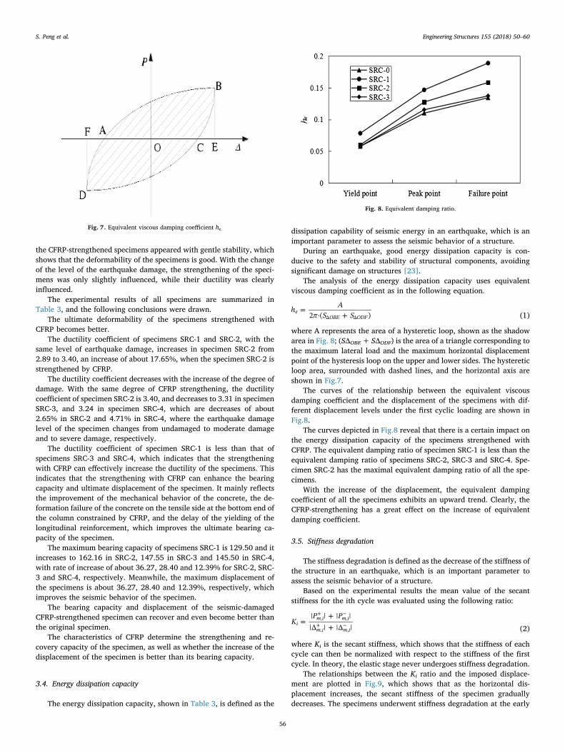
The longitudinal steel bar and section steel are analyzed by theclassical ideal elastic-plastic model. CFRP is composed of orthogonalanisotropic materials, whose tensile stress along the fiber directionshould be considered in the analysis, and the ideal elastic material isdefined before it reaches the tensile strength. The stress-strain re-lationship of concrete is shown in Fig. 11 and the stress-strain re-lationship of the section of steel and CFRP is shown in Fig. 12.
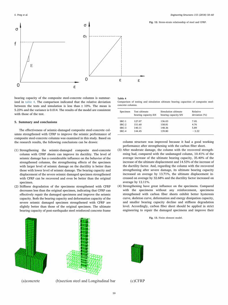
4.2. Element type
The section of steel and concrete are reduced integration usingeight-node solid elements (C3D8R), longitudinal bar and stirrups aredual-node truss element (T3D2), and CFRP is a four-node reductionintegral membrane unit (M3D4R) [33]. Interaction on the contactsurface between the section of steel and concrete are mainly normal andtangential whose spring elements were set as Spring 2. Spring stiffnessin the normal direction is infinite, and that in the tangential should beset according to the bond strength. The finite element model is shown inFig.13.
Boundary conditions of the model and that of the testing are con-sistent, and the column bottom restrains the freedom of translationalmotion and the t rotational motion on the direction of X, Y, Z to si-mulate the base binding effect of capitals placed on the rigid plate. Plateand capitals use bind (tie) connection.
The concentrated load was applied to simulate the vertical load thatis applied to the jack while repeatedly applying horizontal displacementcontrol at the loading point.
4.3. Comparisons of analytical and test results
The analytically predicted backbone envelope load-displacementresponses against the measured cyclic response of the columns areshown in Figs. 4 and 6, which indicate that the non-linear analysismodel predicts the envelope load-displacement response well.
The comparison of the testing and simulation of the ultimate
1stag2stag
Dashe
unrestrain Weak constraint
co
cp
c
c0 co
E
Ecp
Fig. 11. Stress-strain relationship of concrete.
S. Peng et al. Engineering Structures 155 (2018) 50–60
58
bearing capacity of the composite steel-concrete columns is summar-ized in table 4. The comparison indicated that the relative deviationbetween the tests and simulation is less than±10%. The mean is5.23% and the variance is 0.014. The results of the model are consistentwith those of the test.
5. Summary and conclusions
The effectiveness of seismic-damaged composite steel-concrete col-umns strengthened with CFRP to improve the seismic performance ofcomposite steel-concrete columns was examined in this study. Based onthe research results, the following conclusions can be drawn:
(1) Strengthening the seismic-damaged composite steel-concretecolumn with CFRP sheets can improve its ductility. The level ofseismic damage has a considerable influence on the behavior of thestrengthened columns, the strengthening effects of the specimenwith larger level of seismic damage on the ductility is better thanthose with lower level of seismic damage. The bearing capacity anddisplacement of the severe seismic damaged specimen strengthenedwith CFRP can be recovered and even be better than the originalspecimen.
(2) Stiffness degradation of the specimens strengthened with CFRPdecreases less than the original specimen, indicating that CFRP caneffectively repair the damaged specimens and improve the seismiccapacity. Both the bearing capacity and deformation capacity of thesevere seismic damaged specimen strengthened with CFRP areslightly better than those of the original specimen. The ultimatebearing capacity of post-earthquake steel reinforced concrete frame
column structure was improved because it had a good workingperformance after strengthening with the carbon fiber sheet.
(3) After moderate damage, the column with the recovered strength-ening had, compared with the undamaged column, 10.41% of theaverage increase of the ultimate bearing capacity, 35.40% of theincrease of the ultimate displacement and 14.53% of the increase ofthe ductility factor. And, regarding the column with the recoveredstrengthening after severe damage, its ultimate bearing capacityincreased on average by 13.71%, the ultimate displacement in-creased on average by 32.68% and the ductility factor increased onaverage by 12.11%.
(4) Strengthening have great influence on the specimens. Comparedwith the specimens without any reinforcement, specimensstrengthened with carbon fiber sheets exhibit better hysteresiscurve, skeleton curve, deformation and energy dissipation capacity,and smaller bearing capacity decline and stiffness degradationlevel. Accordingly, carbon fiber sheet should be applied in strictengineering to repair the damaged specimens and improve their
f
E
0
f
0
Fig. 12. Stress-strain relationship of steel and CFRP.
(a)concrete (b)section steel and Longitudinal bar (c)CFRP
Fig. 13. Finite element model.
Table 4Comparison of testing and simulation ultimate bearing capacities of composite steel-concrete columns.
Specimen Test ultimatebearing capacity/kN
Simulation ultimatebearing capacity/kN
Relativedeviation (%)
SRC-1 127.07 136.03 7.05SRC-2 151.60 158.81 4.76SRC-3 140.11 148.36 5.89SRC-4 144.45 139.80 −3.22
S. Peng et al. Engineering Structures 155 (2018) 50–60
59

seismic performance.(5) The comparisons were made using the nonlinear finite element
software, ABAQUS, to simulate four different conditions includingthe original column, undamaged strengthened column, moderateand severe damage. Based on the testing data, the hysteresis curves,skeleton curves, strength degradation and stiffness degradation ofthe post-earthquake seismic-damaged steel reinforced concreteframe column structures strengthened with CFRP were analyzed. Anon-linear analysis model was developed for predicting the en-velope load-displacement response, and the results of the model areconsistent with those of the test.
6. Foundation item
This research is funded by ‘National Natural Science Foundation ofChina (CN)’ – ‘China’ (Grant No. 51108041, 51478048), ‘Young andMiddle-aged Scientific and Technological Innovation Team Foundationof Hubei Province of China (CN)’ – ‘China’ (Grant No. T201303) andtheir support is gratefully acknowledged.
Appendix A. Supplementary material
Supplementary data associated with this article can be found, in theonline version, at http://dx.doi.org/10.1016/j.engstruct.2017.10.065.
References
[1] Nie JG, Tao MX, Huang Y, Chen G. Research advances of steel-concrete compositestructural systems. J Build Struct 2010;31:71–80. [in Chinese].
[2] Li J, Feng DC, Gao XL, Zhang YS. Stochastic nonlinear behavior of reinforcedconcrete frames. I: Experimental investigation. J Struct Eng 2016;142:0733–9445.
[3] Zhang PZ, Hou S, Ou PJ. A beam-column joint element for analysis of reinforcedconcrete frame structures. Eng Struct 2016;118:125–36.
[4] Feng DC, Li J. Stochastic nonlinear behavior of reinforced concrete frames. II: nu-merical simulation. J Struct Eng 2016;142:04015163.
[5] Chen CC, Chen CC, Hoang TT. Role of concrete confinement of wide-flange struc-tural steel shape in steel reinforced concrete columns under cyclic loading. EngStruct 2016;110:0141–296.
[6] Xu CX, Zeng L, Zhou Q, Tu X, Wu Y. Cyclic performance of concrete-encasedcomposite columns with T-shaped steel sections. Int J Eng Sci 2015;61:455–67.
[7] Guo ZX, Lin H, Liu Y. Experimental study on seismic behavior of SRC columns withdifferent stirrup configuration. J Build Struct 2010;31:110–5. [in Chinese].
[8] Leon R. An experimental study on strength and serviceability of reinforced and steelfiber reinforced concrete (SFRC) continuous composite slabs. Eng Struct2016;114:171–80.
[9] Lampropoulos AP, Paschalis SA, Tsioulou OT, Dritsos SE. Strengthening of re-inforced concrete beams using ultra high performance fibre reinforced concrete(UHPFRC). Eng Struct 2016;106:370–84.
[10] RUCT ENT, Noshiravani, E. Brühwiler. Analytical model for predicting response andflexure-shear resistance of composite beams combining reinforced ultrahigh per-formance fiber-reinforced concrete and reinforced concrete. J STG 2014; 140:
1299–28.[11] Yoo DY, Banthia N, Yoon YS. Flexural behavior of ultra-high-performance fiber-
reinforced concrete beams reinforced with GFRP and steel rebars. Eng Struct2016;111:246–62.
[12] Wang X, Sayed AM, Wu ZS. Modeling of the flexural fatigue capacity of RC beamsstrengthened with FRP sheets based on finite-element simulation. J Struct Eng2015;141:04014189.
[13] Yin SF, Hu KX. Numerical simulation for the pseudo-static test of strengthened RCcolumns with earthquake-damage based on opensees. Eng Struct 2015;31:145–51.
[14] ACI Committee 318. Building code requirements for structural concrete (ACI 318-05) and commentary (ACI 318R-05). American Concrete Institute; 2005 [inAmerican].
[15] YB 9082-2006. Technical specification of steel-reinforced concrete structures.National Development and Reform Commission of the PRC; 2006 [in Chinese].
[16] JGJ 138-2001. Technical specification for steel reinforced concrete compositestructures. Architecture Industrial Press of China; 2001 [in Chinese].
[17] AIJ-SRC. Standard for the calculation of steel-reinforced concrete structures.Architectural institute of Japan; 2010 [in Japanese].
[18] Kim SH, Choi JH. Repair of earthquake damaged RC columns with stainless steelwire mesh composite. Adv Struct Eng 2010;13:393–402.
[19] Zhao G, Cao FB. Seismic behavior of reinforced concrete crack-short columnsstrengthened with CFRP. Earthq Resistant Eng Retrofitting 2010;132:15–9. [inChinese].
[20] Xu CX, Peng W, Xu KL, Zhou L. Experimental research on seismic behavior of CFRP-strengthened seismic-damaged exterior joints in composite frame consisting ofCFSST columns and steel beams. J Struct Eng 2014;135:69–76.
[21] Zhang YB. Experimental study on seismic behavior of RC frame columns strength-ened with new material. Tongji University, ShangHai; 2012 [in Chinese].
[22] Wang ZM. Experimental study and theoretical analysis on the vibration table ofseismic damage RC frame strengthened with new material. Tongji University,ShangHai; 2012 [in Chinese].
[23] Karayannis CG, Sirkelis G. Strengthening and rehabilitation of RC beam–columnjoints using carbon-FRP jacketing and epoxy resin injection. J Earthq Eng Struct D2008;37:769–90.
[24] Ozbakkaloglu T, Saatcioglu M. Seismic performance of square high-strength con-crete columns in FRP stay-in-place formwork. J Struct Eng, ASCE 2007;133:44–56.
[25] Ozbakkaloglu T, Saatcioglu M. Seismic behavior of high-strength concrete columnsconfined by fiber reinforced polymer tubes. J Compos Constr 2006;10:538–49.
[26] Idris Y, Ozbakkaloglu T. Behavior of square fiber reinforced polymer-high-strengthconcrete-steel double-skin tubular columns under combined axial compression andreversed-cyclic lateral loading. Eng Struct 2016;118:307–19.
[27] Idris Y, Ozbakkaloglu T. Seismic behavior of high-strength concrete-filled FRP tubecolumns. J Compos Constr 2013;17:04013013.
[28] Idris Y, Ozbakkaloglu T. Seismic behavior of FRP-high-strength concrete-steeldouble skin tubular columns. J Struct Eng, ASCE 2012;140:1299–328.
[29] Professional Standard of the People's Republic of China. Specificating of TestingMethods for Earthquake Resistant Building (JGJ 101–96). Beijing, China: ChinaArchitecture and Building Press; 1997. [in Chinese].
[30] Hou PJ. Research on the seismic damage modle of steel reinforced high strength andhigh proformance concrete frame. Xi’ An: Xi'an University of Architecture andTechnology; 2009 [in Chinese].
[31] Yang W, Wu G, Wu ZS, Gu DS, Guo ZS. Ductility analysis of FRP-confined shortrectangular reinforced concrete columns. J Earthquake Eng Eng Vibrat2009;29:71–6. [in Chinese].
[32] Ozbakkaloglu T, Jian CL. Axial compressive behavior of FRP-confined concrete:experimental test database and a new design-oriented model. Compos Part B-Eng2013;55:607–34.
[33] Jian CL, Ozbakkaloglu T. Confinement model for FRP-confined high-strength con-crete. J Compos Constr, ASCE 2013;18:2537–47.
S. Peng et al. Engineering Structures 155 (2018) 50–60
60