experimental investigation of a timber-concrete floor
TRANSCRIPT
Experimental investigation of a timber-concrete floor panel system with a hybrid glass
fibre reinforced polymer-timber corrugated core
Ya Ou a, Joseph M. Gattas a, Dilum Fernando a,*, José L. Torero b
a School of Civil Engineering, University of Queensland, Australia
b Department of Civil, Environmental and Geomatic Engineering, University College London, United
Kingdom
* Corresponding author. E-mail address: [email protected] (D. Fernando).
Abstract
Hybrid timber-concrete (HTC) floor systems are well-suited for prefabricated construction and so have
seen widespread use in modern sustainable buildings. This paper investigates a novel extension to such
systems by introducing a corrugated core between tensile timber and compressive concrete layers. This
new “HTCC” floor panel system is hypothesised to have an increased weight-specific flexural capacity
relative to HTC systems, by reducing the volume of concrete below the panel neutral axis without
decreasing flexural capacity. This paper experimentally investigates the flexural performance of the
new system, acting in two configurations: with core orientation parallel to the span for maximum
longitudinal one-way spanning capacity; and with core orientation transverse to the span for generation
of a novel transverse spanning capacity. In total, eight HTCC floor panels were prepared and tested,
with the flexural capacities and critical failure modes analysed for each. Effects of different core
geometries, shear force transfer methods, and manifested composite action are also closely studied.
Longitudinal specimens achieved the best composite action and correspondingly the highest panel
performance, with a 73% ultimate moment carrying efficiency and an 85% stiffness efficiency at SLS,
compared to an idealised HTC section with full composite action.
Keywords: Composite structure; GFRP-timber corrugated core; Hybrid timber-concrete floor panel
1. Introduction
Hybrid timber-concrete (HTC) floor panels are a lightweight and sustainable alternative to
conventional reinforced concrete floor systems [1]. They have been used on a number of recent projects,
including new construction [2], refurbishment of old timber floors [3-5], and as bridge decks [6-9]. HTC
floor panels consist of a timber layer acting as the tensile reinforcement and a concrete layer acting as
the compression element, with composite action achieved through the bi-material interface by adhesive
bonding or mechanical anchoring [2, 10]. The panels are economical to construct as they can be entirely
or partially pre-fabricated [11], with the latter case having timber fabricated off-site and installed on-
site as permanent structural formwork for concrete casting.
The flexural behaviours of HTC floor panels have been characterised through extensive testing of
full-scale specimens [12-19]. These studies have shown that HTC floor panels have a higher load
carrying capacity and out-of-plane rigidity compared to the traditional timber floor systems [20, 21] and
a higher load-to-weight ratio than reinforced concrete floor panels [21]. Experimental studies have also
revealed that perfect composite action between concrete and timber is difficult to achieve, with shear
slip at the timber-concrete bi-material interface having a substantial effect on panel stiffness and
strength [15, 22]. Of shear connectors types investigated for HTC systems, adhesive bonding provides
the highest composite action [1, 10], however the key problem with most connector types is that the
timber-concrete interface is located below the neutral axis; when slip occurs, concrete is subjected to
high tensile stress and interfacial connectivity is reduced as cracking develops. This contributes to
further shear slip and tensile concrete stresses; which leads to a significant volume of cracked concrete
which contributes little to panel flexural capacity.
This paper investigates the flexural behaviour of a novel hybrid HTC floor panel which introduces
a corrugated core layer as shown in Fig. 1. The “HTCC” panel is hypothesised to reduce the tensile
concrete inefficiencies exhibited by conventional HTC panels (Fig. 2a), for an improved overall load-
to-weight flexural capacity. Sections 2 first describes the design, geometric details, and fabrication of
specimens. Section 3 then presents the experimental program and test results, including load-
displacement behaviour, failure modes, and composite action. Section 4 assesses the experimental
results and the performance of the HTCC panels and compares with the idealised HTC systems with
full composite action.
2. Floor panel design and fabrication
2.1. Core geometry and material selection
The key innovation proposed in the HTCC system is the introduction of an additional core layer
which can reduce the volume of concrete under the neutral axis, without negatively effecting panel
flexural capacity. A corrugated pattern was selected as the core shape with these characteristics, as
shown in Fig. 1. Voids below the core are left hollow, reducing concrete volume and providing a
potential conduit for building service cables. With reference to Fig. 2a-b, the core corrugation introduces
two interfaces in place of the single concrete-timber interface in HTC systems, with core-timber and
concrete-core interfaces along corrugated valley and ridge surfaces, respectively.
The concrete-core ridge interface is above the neutral axis to minimise loss of composite action
through tensile cracking in the concrete, however core material choice will have a strong impact on the
overall composite action manifested by the HTCC system. A GFRP-timber laminate was chosen as the
core material as it is economical and easy to manufacture, has mechanical properties significantly above
a pure timber structure, and has a reduced weight and carbon intensity as compared to a steel material
[23-26]. More importantly, it can act as a waterproof layer to protect the timber from the moisture
introduced by concrete casting and can allow a strong bonded connection between the core and timber
layers.
2.2. Core and panel dimensions
The core and panel dimensions in an initial HTCC specimen were designed to ensure two criteria
are met: (a) the concrete volume was reduced by at least 40% compared with an HTC panel section of
the same overall height; and (b) the neutral axis of the section remained within the core so the top
concrete acted predominantly in compression. Selected specimen cross sectional dimensions are shown
in Fig. 2c. The total height of the specimen was 160mm which was consistent with similar existing
experimental studies of HTC floor panels [15, 17]. Core height, ridge length, and valley length
dimensions gave a 47% reduction in concrete weight compared a HTC specimen of the same height.
The section neutral axis was calculated from a section analysis to be 55.6mm below the top surface,
placing the concrete-core interface and concrete volume predominantly in compression. The section
analysis assumed failure was controlled by the tensile timber failure. Linear elastic material properties
were assumed for tensile timber and plywood, with fibre direction elastic moduli of 12.7GPa and
10.5GPa [27], respectively. Concrete compressive strength was assumed at this first design stage as
35MPa with the compressive stress-strain relationship provided by Eurocode 2 [28] and concrete tensile
strength assumed to be negligible.
A preliminary finite element (FE) analysis was used to design the corrugated core material
thickness to ensure core failures, including buckling and crushing, did not occur in the core prior to the
ultimate load calculated from the section analysis. A three-layer 7mm plywood thickness and 1025gsm
unidirectional GFRP face thickness were found to be adequate for this, with the fibre direction of the
GFRP was parallel to the panel axis and the grain direction of the plywood face layers orthogonal to the
panel axis. Complete model details and assumptions are described in Appendix A.
2.3. Transverse core variations
The above HTCC design introduced a core orientation aligned with panel span direction. There was
no continuous fibre (timber or GFRP) in the direction orthogonal to the span axis for carrying flexural
loads, so it can only be used as one-way spanning slab as is typical for HTC systems. This design is
termed the Longitudinal Core “LC” panel type, with two specimens manufactured for testing as
described in the next section.
The inclusion of a core layer however introduces a novel potential for transverse load carrying
capacity in HTCC slabs. Consider a “Base Core” (BC) configuration, designed with similar dimensions
as LC panels, but with core orientation altered to give continuous GFRP and timber fibres alignment as
shown in Fig. 3 and Fig. 4a. Continuous tensile fibres in the span direction would be expected to give a
significant transverse load carrying capacity, while preserving other key benefits of the HTCC system:
a concrete volume reduction, ease of manufacture, and hollow conduits for building services.
However, when the core is orthogonal to the panel span, the bond line between the core and tensile
timber is discontinuous, which is likely to result in stress concentration at the edges of core valley plates,
and has lower bond area. This introduces a high risk of debonding failure at the interface between core
valley and tensile timber. To investigate the behaviour of transverse HTCC panels and navigate the
potential sensitivity of interfacial behaviour between core and the tensile timber, two BC specimens
were manufactured with different core-timber interfacial connectivities: one with direct bonding only,
and one with bonding and additional shear bolt reinforcement.
Interfacial shear behaviour can also be modified with adjustment to the core geometry itself, which
gives an additional designer ability to control or modify panel performance. Two additional core
configurations were designed to investigate this. “High Core” (HC) specimens had the same valley and
ridge plate sizing as BC but with the core height increased to 120mm, increasing the second moment of
inertia as shown in Fig. 4b. “Skinny Core” (SC) specimens were designed with the same core height
and ridge plate size as the BC design, but with a lower timber-core shear capacity within each corrugated
unit, from reduced valley plate sizing as shown in Fig. 4c. Again, two specimens of each type were
manufactured, one with and one without shear bolt reinforcement.
To summarise, eight HTCC specimens were designed with properties as listed in Table 1. To
provide a consistent naming, each specimen is designated with a four-letter name. The first two letters
indicate the type of core used: LC, BC, HC, or SC. The third character consists of either number “1” or
“2” to differentiate between two identical core type specimens, while the fourth character is used to
identify if the shear bolt reinforcement was used (“D”) or not (“P”). For example, HC2D is a panel with
a high core and shear reinforcement. Table 1 also lists the weight of each specimen. For transverse
specimens, the concrete volume reduction as compared with a typical HTC section with the same total
section height and timber thickness was 42% for BC, 44% for HC and 51% for SC designs.
2.4. Panel dimensions and materials
All the specimens in this study were designed with a consistent panel length, panel width, concrete
depth above the core ridge, and tensile timber thickness. Overall panel size was 570mm wide and
2400mm long. Total section height was 160mm for LC, BC, and SC panel types, and 190mm for HC
panel types.
Concrete used in all the specimens were from the same batch and with an average 28-day
compressive strength of 41.9MPa, as determined from three concrete cylinder samples according to
Australian Standard AS1012.9 [29]. The corrugated core was composed of a GFRP-timber-GFRP
laminate, consisting of a 7mm plywood board (three-layer fibre) bonded with a layer of 1025gsm
uniaxial GFRP fabric on each face. Commercially-available polyurethane adhesive Purbond was used
for bonding GFRP fabric to plywood within the core and for bonding the corrugated core to tensile
timber. Polyurethane type adhesive was selected because of its high performance in moist environments
[30], as the concrete casting was expected to introduce high moisture content to the bonded interfaces.
Tensile timber layer was formed of three pieces of 35mm thick, 190mm wide pine wood boards with
grain direction parallels to the panel axis, and boards had structural grading of MGP12, in which MGP
represents machine graded pine as per Australian Standard AS1748 [31]; MGP12 indicates a minimum
threshold for stiffness of 12GPa [27, 31].
In all the specimens, 10g-8×100mm chipboard screws were driven approximately 45mm into the
core and tensile timber at a 150mm spacing along core valleys, to prevent the potential peeling failures
at the concrete-core interface. Some reinforcement was also added along the panel support lines for HC
and SC core types, with the two end voids filled with grout as shown in Fig. 4b and c. This was to
eliminate the concrete tensile failure occurring above the core ridge, observed during initial testing of
the base core specimen BC2D, which will be further discussed in Section 3.3.
2.5. Panel fabrication
The manufacturing process of the specimens is briefly presented in this section, with complete
details available in [32]. The GFRP-timber core laminates were first fabricated to the desired corrugated
shape using compression moulding [25] and vacuum bagging [33] techniques (Fig. 5a). After the core
was fully cured, it was bonded to the tensile timber and loaded during curing; when the timber-core
bond was fully cured, chipboard screws were driven into the core and tensile timber (Fig. 5b). Concrete
was cast into plywood formwork and cured in outdoor conditions for a minimum of 28 days (Fig. 5c).
For one of the two transverse core specimens, after the concrete was fully cured, the 103mm long M8
DP10100 RamsetTM DynaBolts were installed from tensile timber bottom surface into the concrete
valley region following the procedure described in [34] (Fig. 5d). Finally, for SC and HC specimens,
the first void at each end of the panel was filled with grout and left to set for a minimum of 5 days.
Qualitatively, the manufacturing method was found to be easy, low cost, and provide very good quality
specimens based on visual inspection.
3. Experimental test and results
3.1. Testing method and instrumentation
All specimens were tested under four-point bending, with a schematic test setup shown in Fig. 6.
Load was applied using a 1MN servo hydraulic MTS machine with displacement control at a rate of 2
mm per minute. A spreader beam was used under the MTS crosshead to apply two line loads on the
specimen. The clear span between supports was 2200mm and the distance between two loading lines
was 640mm.
To capture the vertical deformation of the panel, four linear position transducers LP1-LP4 were
used. To measure the relative slip between the tensile timber and the concrete block, two linear variable
displacement transducers (LVDTs) LVDT1 and LVDT2 were placed at panel ends. To measure the
strain distribution of mid-span regions, a digital image correlation (DIC) system was used to measure a
region with width varying from 340mm to 500mm, shown in Fig. 6. Finally, strain gauges were placed
at the concrete top and timber bottom surfaces around mid-span to measure the axial strain in different
layers. For longitudinal type specimens, strain gauges were only installed at the mid-span section, and
for transverse type specimens, strain gauges were installed at both mid-ridge and mid-valley sections.
3.2. Load-displacement behaviour
The obtained specimen load versus mid-span deflection curves are shown in Fig. 7. Key load values
are summarised in Table 2 at both the ultimate load state (ULS) and the serviceability limit state (SLS),
taken at a mid-span displacement of 7.3mm (span/300) [35]. For Fig. 7, the left-hand side vertical axis
shows the total load, while the right-hand side vertical axis shows the equivalent uniformly distributed
load (UDL), with equivalency defined for a UDL to give the same maximum bending moment as the
concentrated load.
Looking at specimen behaviour up to the ULS, significant variation in load capacity is seen between
specimens, corresponding to each of the variations introduced for core orientation, transverse interfacial
shear reinforcement, and transverse core geometry:
(a) Core orientation: Longitudinal-cored specimens LC1P and LC2P showed the highest ultimate load
of all tested specimens (71.7kN), 57% higher than the nearest transverse core with similar height,
BC1P (45.7kN). However, LC cores only had a 3% higher capacity compared to the best-
performing transverse core specimen, HC2D (69.9kN). The transverse core additionally showed a
higher deformation capacity at failure (84.7mm) compared to that of LC specimens (60.6mm and
44.9mm). These results indicate that while one-way spanning LC specimens are the most efficient
HTCC configuration, HTCC systems with transverse core are able to introduce transverse loading
capacity without significantly compromising the longitudinal loading capacity.

(b) Transverse interfacial shear reinforcement: DynaBolt-reinforced transverse specimens BC2D and
HC2D and SC2D showed 9.2%, 86.2% and 19.7% higher load carrying capacity than their
counterparts without DynaBolts. Non-reinforced specimens showed a highly ductile response,
undergoing a very large deformation without significant load decrease. These results indicate that
enhancing the interlayer shear force transfer has significant positive effects on the load carrying
capacity of the transverse-cored specimens, likely due to the increased composite action between
the layers.
(c) Transverse core geometry: Comparing transverse specimens with different core geometries, high-
cored HC2D and skinny-cored SC2D showed 18~20% higher weight-specific capacity than the
base-cored BC2D. For SC specimens, results indicate performance improvement is mostly
attributed to decreasing the weight of non-performative concrete. For HC specimens, performance
improvement is primarily seen in Dynabolt-reinforced specimens and attributed to the efficiency
of deeper section size. SC1P also achieved an 8% higher capacity than BC1P, which can be
attributed in part to lack of grout filling in the BC1P specimen.
Looking at load-deflection behaviour up to the SLS in Fig. 7b, all curves were initially
approximately linear. Longitudinal-cored specimens showed the highest initial stiffness among all
specimens because of the constant section along the span, resulting in a higher overall second moment
of area than the other specimens. DynaBolt-reinforced specimens BC2D, HC2D, and SC2D showed
higher initial stiffness compared to their counterparts BC1P, HC1P, and SC1P, as DynaBolts effectively
reduced the shear slip between the core and tensile timber layers. This will be investigated more closely
in Section 3.3. When comparing the core geometry among the transverse-cored specimens, HC
specimens had the highest stiffness because of their deep section height, BC specimens had a slightly
lower stiffness, while the SC specimens had a lower stiffness than both, particularly for reinforced
specimens. The reduced bonding area within each corrugated unit and higher cross-section variation
along the span may have contributed to a higher slip and a corresponding stiffness reduction in SC
specimens. SC specimens also have the lowest flexural stiffness of tested panels, thus the lowest
interfacial slip compared to HC and BC specimens. The introduction of DynaBolts is therefore likely to
have a reduced effect on the SC response within the early loading stages.
3.3. Failure modes
The failure modes of each core type were closely documented to establish how they contributed to
the flexural performances observed above. Fig.8 shows the following failure modes observed during
the tests:
i. Debonding at the (a) corrugated core-tensile timber interface (F1), (b) concrete-corrugated core
interface (F2), and (c) GFRP-plywood bi-material interface within the core (F3).
ii. Concrete cracks developed from core corner regions (d) between loading points (F4), (e)
between supports and loading points (F5), and (f) longitudinal cracking (F6).
iii. Other concrete cracking: (g) flexural cracks in the region between loading points in longitudinal
specimen (F7), (h) flexural-shear cracks in the regions between supports and loading points in
longitudinal specimen (F8), (i) top surface cracking above the supports (F9), and (j) surface
cracking near the grout-filled voids (F10).
iv. Material failures including (k) timber tensile rupture failure (F11), and (l) concrete crushing at
the top surface between loading points (F12).
Load-displacement curves, interfacial shear slip curves, and failure modes of LC1P and LC2P are
as shown in Fig. 9. Specimens had good consistency and repeatability of behaviour, which gives
confidence to the validity of data collected for the individual specimens tested for each of the transverse-
core configurations. Due to consistency between LC specimens, only LC1P is discussed henceforth.
Concrete flexural-shear cracks initiated between supports and loading points (F8, Fig. 9d) at mid-span
deflection of 6.6mm. Vertical flexural cracks appeared between the loading points (F7, Fig. 9c) at
deflection of 16.8mm and fully developed across the height of the concrete layer, becoming the
dominant failure. A clear longitudinal crack (F6, Fig. 9e) was also observed when the displacement was

about 38.0mm. The measured slip between concrete and tensile timber at the panel ends were found to
have a similar trend until about 40mm deflection, indicating symmetry of the interface behaviour at
initial stages. This symmetry was however lost beyond 40mm mid-span deflection and as the ultimate
load is reached, with at maximum end slip of approximately 8-17mm.
Looking next at the transverse specimens, load-displacement curves, interfacial shear slip curves,
and failure modes of base-cored specimen with no shear reinforcement (BC1P) shown in Fig. 10.
Interfacial shear deformations (failure mode F1, Fig. 10c) started at mid-span deflection of 7.4mm, full
debonding of the concrete core from the corrugated plate was observed at one end of the specimen (F2,
Fig. 10d) when deflection was about 59.2mm, and debonding at the GFRP-plywood bi-material
interface (F3, Fig. 10e) started at deflection 10mm. Cracks started to appear from corrugation corners
between loading points and supports (F5, Fig. 10g) when deflection was 13.7mm, and cracks happened
between the two loading points (F4, Fig. 10f) at deflection 59.2mm. Ultimate failure occurred at a
deflection of 94.7mm due to fully developed cracks in F4 and F5, with subsequent deflection leading to
timber tensile rupture failure (F11, Fig. 10h) at deflection 123.8mm. Shear slip values are plotted in Fig.
10b and show that values at each end are similar to each other, remain low up to the SLS, and then
increase rapidly to ULS, ended at about 24-28mm at both ends, which were much larger than the LC
type specimens.
Shear reinforced specimen BC2D failure data is also shown in Fig. 10 for comparison to its
counterpart BC1P. Initial failure was observed as cracking on the concrete surface above one support
(F9, Fig. 10i) at deflection 9.2mm, which then grew to become a fully developed across the width of
the panel. F5 cracking (Fig. 10j) appeared from 25.8mm and fully developed across the height of
concrete layer, until causing ultimate failure at deflection of 35.4mm. Shear slip values as plotted in Fig.
10b, captured only at one end due to equipment malfunction, show a positive then negative slip due to
movement of the end concrete block from F9. Comparing between BC1P and BC2D, DynaBolt-
reinforcement effectively suppressed debonding failures F1, F2 and F3.
The initial F9 failure of specimen BC2D occurred directly above the void in the end support region
(Fig. 10i). For this reason, subsequent high-cored and skinny-cored samples had grout-filled end voids
to provide support line reinforcement. HC2D and SC2D failure modes and responses are shown in Fig.
10 and it was seen that F9 was suppressed for both HC2D and SC2D. Initial failure was F5 at mid-span
deflection of 10.7mm and 4mm for HC2D and SC2D, respectively. For HC2D, these cracks then
developed between corrugated corners (Fig. 11c), rather than across the height of the concrete layer as
seen previously in BC1P specimens (Fig. 10g), until full separation of the top concrete layer occurred
at deflection 88.7mm. A concrete crack emerged above the corrugation corner beside one filled void
(F10, Fig. 11d) at deflection 11.5mm, however this crack did not develop to the full depth of the ridge
before the end of the test. For SC2D, F5 cracks developed parallel to the panel axis and through the
depth of the concrete layer (Fig. 11e). F10 again occurred early, at deflection of 16.6mm, but did not
fully develop. Crushing at the top surface of the concrete (F12, Fig. 11f) also occurred between loading
points when deflection reached 75.1mm.
The results of shear reinforced and non-reinforced HC and SC types are similar to that for BC types,
although F2 and F3 did not occur in HC1P or SC1P, with the former suppressed by end void filling and
the latter suppressed with improved manufacturing and a better bond quality between GFRP and
plywood. Slip values for HC2D and SC2D are shown in Fig. 11b and slip again developed more quickly
after reaching SLS, but with low final end slip for both specimens (less than 10mm) as compared to
unreinforced specimens.
3.4. Axial strain distribution through panel depth
Panel axial strain distribution was analysed from the collected DIC data. In the transverse pattern
specimens, one ridge section and one valley section near mid-span (Fig. 12a) were chosen to show the
through depth strain distribution, while in longitudinal specimens only the mid-span section (Fig. 12b)
was analysed because of the constant section along the span. Strain distributions at the SLS and ULS
are given in Fig. 13 for one longitudinal-cored specimen (LC1P) and two transverse-cored specimens
(HC1P, HC2D). In Fig. 13, y=0 represents the top surface of the concrete and y=-160 (Fig. 13a) or y=-
190 (Fig. 13b-e) represents the bottom surface of the timber. Top and bottom surface strain gauge (SG)
readings are also shown in Fig. 13 and show good correlation with DIC values.
In the longitudinal pattern specimen LC1P (Fig. 13a), strain within concrete was nonlinear.
Concrete above the corrugated core ridge surface was under compression at both the SLS and ULS
stages, though part of the concrete within the core height was in tension. The timber layer was under
tension at the SLS stage, which indicates high composite action was achieved in LC1P until SLS.
However, at the ultimate stage, upper part of the timber was under compression because of the loss of
composite action. For HC1P and HC2D in Fig. 13b-e, it can be found that the concrete strain within the
valley section (Fig. 13b and d) showed high nonlinearity along the section height, especially in
DynaBolt-reinforced HC2D. Concrete strain in the ridge section (Fig. 13c and e) distributed
approximately linearly above the core. Until the SLS, concrete and timber layers acted predominantly
in compression and tension respectively. Though some tension was observed in HC1P within concrete
at SLS, the region of concrete acting in tension was negligible in HC2D. This indicates high composite
action achieved in HC2D until SLS. However, at the ULS, both concrete and bottom timber showed
tension and compression regions, again indicating the reduction of composite action.
In all the specimens, there were strain differences at the bi-material interface and this difference
increased from SLS to ULS. This again indicates the reduction of composite action in the panels.
Meanwhile, it can be noticed that the maximum compressive strains on top surface of the concrete in
HC2D (Fig. 13d and e) and LC1P (Fig. 13a) were higher than that in HC1P (Fig. 13b and c), indicating
a greater concrete utilization in the former two specimens.
4. Discussion
4.1. Critical failure modes
Two failure modes dominated HTCC floor panel performance: concrete cracking initiated at the
corrugated core corners and interfacial shear slip between the corrugated core and tensile timber. In all
the specimens, cracks at corrugated corners were observed during early stages of loading, and fully
developed towards the ultimate state. For specimens with transverse core geometries, these cracks were
shown to affect the load carrying capacity of the specimens, especially resulting in loss of composite
action due to discontinuities. Initiation of the cracks correspond to stress concentrations at the
corrugation corners as seen for example in Fig. 12a. Such stress concentrations could be reduced with
smoother corners, which could potentially delay the cracking of concrete.
Large interfacial shear deformations were observed in transverse cores with no DynaBolt-
reinforcement, but this deformation was suppressed with the addition of the interlayer DynaBolt
reinforcement. These reinforced specimens had increased stiffness, load carrying capacity and concrete
use compared to their non-reinforced counterpart, due to the higher composite action achieved by the
reinforced interface. In contrast, longitudinal panels showed a similarly high stiffness and strength
without DynaBolt-reinforcement, as the continuous bonding interface allowed more effective shear
force transfer compared to the discontinuous bond lines in the transverse-cored specimens.
4.2. Variations in flexural behaviour
Strain distribution results show that the flexural behaviour of HTCC floor panels varied between
SLS and ULS states and, in transverse cases, varied between mid-ridge and mid-valley regions. High
composite action was observed until SLS, indicating the initial design methodology based on section
analysis assuming perfect composite action was valid up to SLS. This also indicated that concrete will
not crack at the interface between the core and concrete until SLS, which is important to the long-term
behaviour of the HTCC panels.
As the load increased past SLS, reduction of composite action was seen as evidenced by strain
discontinuities between layers and concrete and timber being subjected to both tensile and compressive
stresses, respectively. Cracking of concrete and shear slip at the corrugated core-tensile timber interface
was observed as the load increased past SLS and reduced panel composite action and flexural capacity.
Reduction in slip at the corrugated core-tensile timber through the use of DynaBolts was seen to enhance
the composite action between the layers and the flexural capacity of the panels. Nevertheless, highly
nonlinear strain distributions across the height of the specimens were observed beyond SLS loads and
indicate that a section analysis based on linear strain distribution cannot accurately predict the ultimate
flexural capacity.
For transverse core specimens, strain distribution across the height was found to be different
between the mid-valley and mid-ridge regions. At ULS, concrete strain variations across the height of
mid-valley regions were highly non-linear, while strain distribution across the height of concrete in mid-
ridge regions were found to show much less nonlinearity. The location of zero strain was also found to
vary between adjacent mid-valley and mid-ridge regions. This change in zero strain location indicates
the uneven distribution of moment of inertia along the length, which results in localized moments and
crack initiation at corner regions. Similarly, at the end regions, this change in section moment of inertia
results in hogging moments in concrete, thus creating tensile cracking in top concrete.
4.3. Effectiveness of the GFRP-timber corrugated core
Manufacturing of the GFRP-timber core was found to be easy and cost effective, with no core
timber failures observed in any of the tested HTCC specimens. The transverse-cored specimens without
DynaBolt-reinforcement had failure at the bonded interfaces, which showed that reduced length of
bonding between the core and tensile timber was not capable of fully transferring the shear force at bi-
material interfaces. However, interfacial shear transfer was significantly improved with the use of
DynaBolts. LC1P and LC2P specimens also showed a significant improvement in the interfacial shear
transfer compared to the transverse core specimens with no shear bolt reinforcement. Overall, it can be
concluded that the corrugated core can effectively transfer shear forces between the layers if adequate
bond length is provided, as in the case of longitudinal core specimens. For the core to be effective in
transverse core systems, it is necessary to provide DynaBolts to reinforce the core in interfacial shear
transfer.
4.4. HTCC performance relative to HTC systems with full composite action
The performance of the HTCC systems proposed is compared with the similar HTC sections
(570mm width, 35mm thick timber together with solid concrete of 125mm or 155mm height) with full
interlayer composite action. Companion is made in terms of moment capacity and stiffness efficiency
(Table 3). The stiffness efficiency is defined by Eq. (1) [15]. In (1), D# is the theoretical deflection with
full composite deflection, D$ is the theoretical deflection with no composite deflection, and D% is the
measured deflection of the test specimens.
(1)
The moment capacity of sections with full composite action is calculated using a section analysis
with the material properties listed below, the results are as listed in Table 3. The detailed calculation
methods of deflections (D$, D&) and the moment capacity Mfull in Table 3 are documented in Appendix
B.
(a) Concrete compressive stress-strain behaviour was assumed according to the specifications given
in Eurocode 2 [28], with 28-days mean compressive strength of 43MPa (based on the concrete cylinder
test data);
(b) Concrete tensile strength was assumed to be negligible; and
(c) Linear-elastic stress-strain behaviour for timber as described in AS1720 [27], with a
characteristic tensile strength of 12MPa.
Compared to similar HTC systems with full composite action, HTCC specimens achieved between
30%-73% moment capacity efficiency. LC specimens achieved 73% of the capacity of sections with
full-composite action, demonstrating the relatively high efficiency of those specimens in terms of
resisting interfacial slip and material usage compared to other types of specimens tested in this study.
DynaBolts effectively reduced the shear slip in reinforced transverse specimens, but their achieved
( )( )
Efficiency 100%N I
N C
D DD D
-= ´
-
maximum moment capacity was still only 51%-56% of that of a section with full composite action,
limited by the concrete cracks in the specimens.
In terms of the efficiency at SLS, all specimens showed higher efficiencies than at the ultimate
stage (51%-85%), showing that higher composite action was maintained at this stage. Longitudinal
specimens still had the highest efficiency at SLS (84% and 85%) and transverse specimens with
DynaBolt reinforcement had slightly higher efficiency than their counterparts.
5. Conclusions
This paper has investigated the flexural performance of a series of eight novel hybrid timber-
concrete floor deck with a corrugated GFRP-timber core. These novel HTCC panels reduced the
concrete usage by 42%-51% compared to similar HTC panels with the same concrete and timber height.
From test results, the following conclusions could be drawn:
(a) The corrugated GFRP-timber core is an economical, easy to manufacture system which provides
effective interlayer connectivity in HTCC panels, provided sufficient bond area or additional shear
reinforcement exists to transfer interfacial shear loads.
(b) The corrugated core orientation had a strong effect on the load carrying capacity of the HTCC
specimens. In the four tested core geometries, longitudinal core specimens showed the highest
weight-specific load carrying capacity. They also showed a 73% ultimate moment carrying
efficiency and an 85% stiffness efficiency at SLS, compared to an idealised HTC section with full
composite action.
(c) For transverse core specimens, inclusion of DynaBolt-reinforcement significantly reduced the
interfacial slip and increased panel moment capacity, with reinforced specimens achieving 9.2%-
86.2% higher load carrying capacity as compared to their counterparts without shear reinforcement.
(d) Decreasing the width of core corrugations reduced the non-performative concrete under neutral
axis and so increased the panel weight-specific capacity. However, as it also reduced the bonding
area within each core corrugation unit, the initial stiffness of the panel was also reduced, which was
not desired.
(e) Increasing the core height and introducing DynaBolt interfacial shear reinforcement increased the
stiffness and the strength of transverse core panels. Such specimens were shown to possess a similar
performance to longitudinal core specimens.
Acknowledgement
The authors would like to thank Hyne Timber Pty Ltd. for donating the tensile timber used in this study
and technical staff at the University of Queensland for their assistance in carrying out experimental tests.
The first author is also grateful for the financial support received from China Scholarship Council, and
the second and third authors are grateful for the financial support received from Australian Research
Council Discovery Project funding scheme [grant number DP160103279].
Appendix A. Details of the finite element model for the core design
To check the performance of the core, a preliminary 3D finite element model of the HTCC floor
panel was developed using commercially-available software ABAQUS. Concrete was modelled using
general purpose brick element C3D8R. Constitutive behaviour of the concrete was modelled using
concrete damaged plasticity model available in ABAQUS [36]. Concrete compression strength was
assumed to be 35MPa, while elastic modulus and the stress-strain data were calculated based on
Eurocode 2 [28]. Shell element S4R was used to model the plywood and GFRP layers in the core and
the tensile timber layer. Timber and GFRP layers were modelled as orthotropic linear elastic material.
Elastic modulus of timber parallel to grain (E1) was assumed to 12.70GPa, while elastic modulus in
tangential (E2) and radial (E3) directions were assumed to be 0.99GPa and 1.44GPa respectively. Shear
modulus in different directions were assumed to be G12=1041MPa, G13=1028MPa, G23=165MPa while
Poisson’s ratios were assumed to be v12=0.292, v13=0.328, v23=0.362 [27, 37]. Elastic modulus of GFRP
in fibre direction (E1) was assumed to be 44GPa, while elastic modulus in other two principal directions
(i.e. E2 and E3) were assumed to be 11GPa. Shear modulus of GFRP in different directions were assumed
to be G12=G13=4.5GPa, G23=0.5GPa, while Poisson’s ratios in different directions were assumed to be
v12=v13=0.28, v23=0.1 [38]. Considering the high strength of GFRP compared to timber, failure of GFRP
was ignored. Timber failure was modelled using well-known Hashin failure criterion [39]. The
longitudinal tensile, compressive and shear strengths of timber was assumed to be 20.4MPa, 40MPa,
and 5.6MPa, while transverse tensile, compressive and shear strength of timber was assumed to be
0.8MPa, 17MPa and 5.6MPa [27, 40]. All bonded interfaces were modelled using tie constraints
assuming a perfect bond.
Appendix B. Deflection and moment capacity calculation of the hybrid timber concrete panels in
Table 3
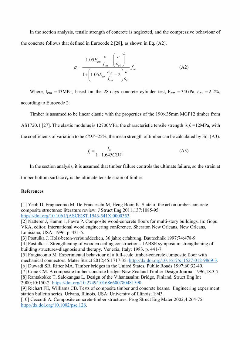
B.1. Deformation at SLS
Deformation of a beam under four point bending as shown in Fig. A1 is calculated by [41]:
(A1)
In this case, the deformation of an HTC beam with no composite action (DN) and full composite
action (DC) can be calculated by replacing EI in Eq. (A3) to be the bending stiffness of a beam with no
composite action(EI), = E#I# + E/I/, or with full composite action (EI)0122 = (EI), +∏45∑45
(7897:;);.
Where E is the elastic modulus, I is the second moment of area, A is the section area, h is the section
height, and the subscripts c and t represent concrete and timber, respectively.
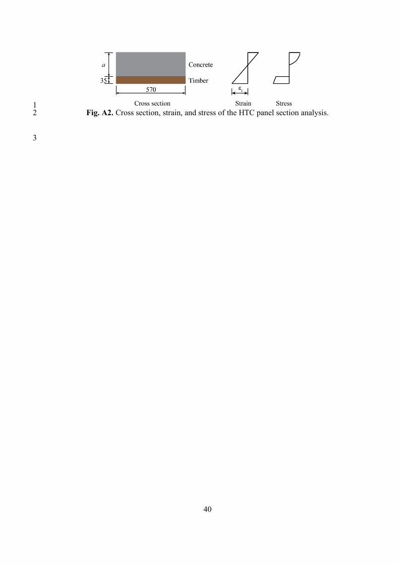
B.2. Moment capacity of HTC
Moment capacity of the HTC section with full composite action in Table 3 is calculated using
section analysis based on sections as shown in Fig. A2. For the sections with height of 160mm, the
concrete depth a=125mm, for the sections with height of 190mm, the concrete depth a=155mm.
3 3 2 2
3 3 2 2
( )( ) ( ) ( ( ) )6
( ( )) ( )6
P L a LD x x a x L L a xLEI L aPa L x L a x L a xLEI a
- é ù= - - + - -ê ú-ë ûé ù+ - - - + -ê úë û
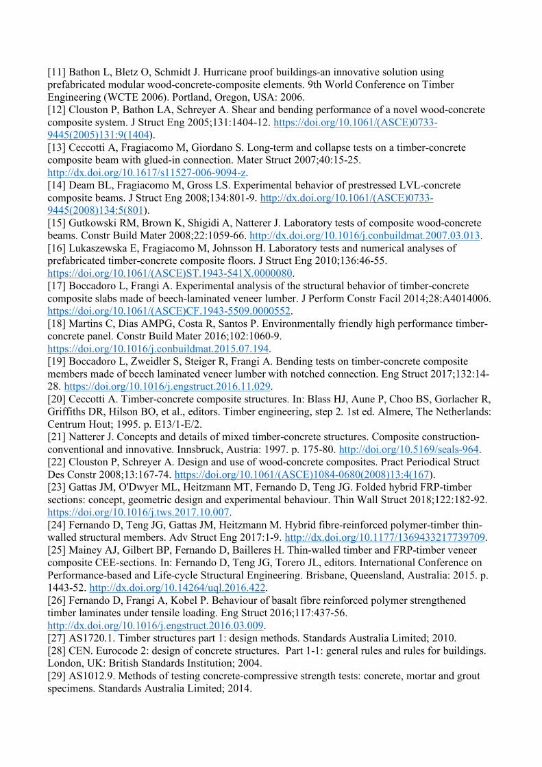
In the section analysis, tensile strength of concrete is neglected, and the compressive behaviour of
the concrete follows that defined in Eurocode 2 [28], as shown in Eq. (A2).
(A2)
Where, f#= =43MPa, based on the 28-days concrete cylinder test, E#= =34GPa, ε#? =2.2%,
according to Eurocode 2.
Timber is assumed to be linear elastic with the properties of the 190×35mm MGP12 timber from
AS1720.1 [27]. The elastic modulus is 12700MPa, the characteristic tensile strength is fct=12MPa, with
the coefficients of variation to be COV=25%, the mean strength of timber can be calculated by Eq. (A3).
(A3)
In the section analysis, it is assumed that timber failure controls the ultimate failure, so the strain at
timber bottom surface ε/ is the ultimate tensile strain of timber.
References
[1] Yeoh D, Fragiacomo M, De Franceschi M, Heng Boon K. State of the art on timber-concrete composite structures: literature review. J Struct Eng 2011;137:1085-95. https://doi.org/10.1061/(ASCE)ST.1943-541X.0000353. [2] Natterer J, Hamm J, Favre P. Composite wood-concrete floors for multi-story buildings. In: Gopu VKA, editor. International wood engineering conference. Sheraton New Orleans, New Orleans, Louisiana, USA: 1996. p. 431-5. [3] Postulka J. Holz-beton-verbunddecken, 36 jahre erfahrung. Bautechnik 1997;74:478-9. [4] Postulka J. Strengthening of wooden ceiling constructions. IABSE symposium strengthening of building structures-diagnosis and therapy. Venezia, Italy: 1983. p. 441-7. [5] Fragiacomo M. Experimental behaviour of a full-scale timber-concrete composite floor with mechanical connectors. Mater Struct 2012;45:1717-35. http://dx.doi.org/10.1617/s11527-012-9869-3. [6] Duwadi SR, Ritter MA. Timber bridges in the United States. Public Roads 1997;60:32-40. [7] Cone CM. A composite timber-concrete bridge. New Zealand Timber Design Journal 1996;18:3-7. [8] Rantakokko T, Salokangas L. Design of the Vihantasalmi Bridge, Finland. Struct Eng Int 2000;10:150-2. https://doi.org/10.2749/101686600780481590. [9] Richart FE, Williams CB. Tests of composite timber and concrete beams. Engineering experiment station bulletin series. Urbana, Illinois, USA: University of Illinois; 1943. [10] Ceccotti A. Composite concrete-timber structures. Prog Struct Eng Mater 2002;4:264-75. http://dx.doi.org/10.1002/pse.126.
2
1
1
1
1.05
1 1.05 2
cmcm c
cmc
cmcm c
Ef
fE
f
e ee
se e
e
æ ö- ç ÷è ø=
æ ö+ -ç ÷è ø
1 1.645ct
tffCOV
=-
[11] Bathon L, Bletz O, Schmidt J. Hurricane proof buildings-an innovative solution using prefabricated modular wood-concrete-composite elements. 9th World Conference on Timber Engineering (WCTE 2006). Portland, Oregon, USA: 2006. [12] Clouston P, Bathon LA, Schreyer A. Shear and bending performance of a novel wood-concrete composite system. J Struct Eng 2005;131:1404-12. https://doi.org/10.1061/(ASCE)0733-9445(2005)131:9(1404). [13] Ceccotti A, Fragiacomo M, Giordano S. Long-term and collapse tests on a timber-concrete composite beam with glued-in connection. Mater Struct 2007;40:15-25. http://dx.doi.org/10.1617/s11527-006-9094-z. [14] Deam BL, Fragiacomo M, Gross LS. Experimental behavior of prestressed LVL-concrete composite beams. J Struct Eng 2008;134:801-9. http://dx.doi.org/10.1061/(ASCE)0733-9445(2008)134:5(801). [15] Gutkowski RM, Brown K, Shigidi A, Natterer J. Laboratory tests of composite wood-concrete beams. Constr Build Mater 2008;22:1059-66. http://dx.doi.org/10.1016/j.conbuildmat.2007.03.013. [16] Lukaszewska E, Fragiacomo M, Johnsson H. Laboratory tests and numerical analyses of prefabricated timber-concrete composite floors. J Struct Eng 2010;136:46-55. https://doi.org/10.1061/(ASCE)ST.1943-541X.0000080. [17] Boccadoro L, Frangi A. Experimental analysis of the structural behavior of timber-concrete composite slabs made of beech-laminated veneer lumber. J Perform Constr Facil 2014;28:A4014006. https://doi.org/10.1061/(ASCE)CF.1943-5509.0000552. [18] Martins C, Dias AMPG, Costa R, Santos P. Environmentally friendly high performance timber-concrete panel. Constr Build Mater 2016;102:1060-9. https://doi.org/10.1016/j.conbuildmat.2015.07.194. [19] Boccadoro L, Zweidler S, Steiger R, Frangi A. Bending tests on timber-concrete composite members made of beech laminated veneer lumber with notched connection. Eng Struct 2017;132:14-28. https://doi.org/10.1016/j.engstruct.2016.11.029. [20] Ceccotti A. Timber-concrete composite structures. In: Blass HJ, Aune P, Choo BS, Gorlacher R, Griffiths DR, Hilson BO, et al., editors. Timber engineering, step 2. 1st ed. Almere, The Netherlands: Centrum Hout; 1995. p. E13/1-E/2. [21] Natterer J. Concepts and details of mixed timber-concrete structures. Composite construction-conventional and innovative. Innsbruck, Austria: 1997. p. 175-80. http://doi.org/10.5169/seals-964. [22] Clouston P, Schreyer A. Design and use of wood-concrete composites. Pract Periodical Struct Des Constr 2008;13:167-74. https://doi.org/10.1061/(ASCE)1084-0680(2008)13:4(167). [23] Gattas JM, O'Dwyer ML, Heitzmann MT, Fernando D, Teng JG. Folded hybrid FRP-timber sections: concept, geometric design and experimental behaviour. Thin Wall Struct 2018;122:182-92. https://doi.org/10.1016/j.tws.2017.10.007. [24] Fernando D, Teng JG, Gattas JM, Heitzmann M. Hybrid fibre-reinforced polymer-timber thin-walled structural members. Adv Struct Eng 2017:1-9. http://dx.doi.org/10.1177/1369433217739709. [25] Mainey AJ, Gilbert BP, Fernando D, Bailleres H. Thin-walled timber and FRP-timber veneer composite CEE-sections. In: Fernando D, Teng JG, Torero JL, editors. International Conference on Performance-based and Life-cycle Structural Engineering. Brisbane, Queensland, Australia: 2015. p. 1443-52. http://dx.doi.org/10.14264/uql.2016.422. [26] Fernando D, Frangi A, Kobel P. Behaviour of basalt fibre reinforced polymer strengthened timber laminates under tensile loading. Eng Struct 2016;117:437-56. http://dx.doi.org/10.1016/j.engstruct.2016.03.009. [27] AS1720.1. Timber structures part 1: design methods. Standards Australia Limited; 2010. [28] CEN. Eurocode 2: design of concrete structures. Part 1-1: general rules and rules for buildings. London, UK: British Standards Institution; 2004. [29] AS1012.9. Methods of testing concrete-compressive strength tests: concrete, mortar and grout specimens. Standards Australia Limited; 2014.
[30] Miao C, Fernando D, Heitzmann MT, Bailleres H. GFRP-to-timber bonded joints: Adhesive selection. International Journal of Adhesion and Adhesives 2019;94:29-39. https://doi.org/10.1016/j.ijadhadh.2019.05.007. [31] AS/NZS 1748. AS/NZS 1748.1 Timber Solid Stress-graded for structural purposes General requirements: Standards Australia; 2011. [32] Ou Y, Fernando D, Gattas JM. Novel hybrid FRP-timber-concrete floor panel system. 6th Asia-Pacific conference on FRP in structures (APFIS-2017). Singapore: 2017. [33] West System. Vacuum bagging techniques. In: West System Inc., editor. 7th ed. Bay City, MI USA: Gougeon Brothers; 2010. [34] Confast. How to Install Concrete Wedge Anchors. 2007. [35] CEN. EN 1995-1-1 Eurocode 5: Design of timber structures. Part 1-1: General - Common rules and rules for buildings: Brussels: BSI; 2004. [36] Systèmes Dassault. Abaqus analysis user's guide (6.13). Abaqus 6.13. Providence, Rhode Island, United States: Simulia Corp; 2014. [37] Forest Products Laboratory. Wood handbook : wood as an engineering material. Centennial edition ed. Madison, Wis: U.S. Dept. of Agriculture, Forest Service, Forest Products Laboratory; 2010. [38] Saghafi H. Mechanical behavior of flat and curved laminates interleaved by electrospun nanofibers. Alma Mater Studiorum Università di Bologna; 2014. [39] Hashin Z. Failure criteria for unidirectional fiber composites. J Appl Mech 1980;47:329-34. http://dx.doi.org/doi:10.1115/1.3153664. [40] Garcia C, Trendafilova I, Zucchelli A, Contreras J. The effect of nylon nanofibers on the dynamic behaviour and the delamination resistance of GFRP composites. In: Manoach E, Stoykov S, Wiercigroch M, editors. MATEC Web of Conferences. Sofia, Bulgaria: 2017. https://doi.org/10.1051/matecconf/201814814001. [41] Pilkey WD. Beams and Columns. In: Pilkey WD, editor. Formulas for Stress, Strain, and Structural Matrices: John Wiley & Sons, Inc.; 2008.
List of Figures
1. Design concept of the HTCC panels.
2. Design concept and dimensions of the HTCC panels: (a) cross section of conventional HTC
panels, (b) cross section of HTCC panels, and (c) dimension of the proposed HTCC (unit: mm).
3. HTCC panel with core orientated transverse to the span.
4. Dimension of the HTCC panels with transverse core (unit: mm): (a) BC, (b) HC, and (c) SC
types.
5. Fabrication process of the HTCC panels: (a) vacuum process for fabricating the core, (b) core
attached to tensile timber, (c) preparation of concrete casting, (d) installed DynaBolts.
6. Test setup and instrumentation of specimens (unit: mm): (a) LC type, (b) BC and HC types, (c)
SC type, and (d) digital image correlation system.
7. Load-displacement curves of tested specimens: (a) full response and (b) response in initial SLS
region.
8. Failure modes of the specimens. (a)-(l): F1-F12.
9. Results for LC1P and LC2P specimens: (a) force-displacement response, (b) interfacial slip-
displacement curve, (c)-(e) failure modes.
10. Results for BC1P and BC2D specimens: (a) force-displacement response, (b) interfacial slip-
displacement curve, (c)-(h) BC1P failure modes, (i)-(j) BC2D failure modes.
11. Results for HC2D and SC2D specimens: (a) force-displacement response, (b) interfacial slip-
displacement curve, (c) HC2D failure modes, (d)-(f) SC2D failure modes.
12. DIC strain and through-depth sections for (a) BC, HC and SC core and (b) LC core.
13. Axial strain distribution through panel depth near mid-span: (a) section 1 in LC1P, (b)-(c) section
1 and 2 in HC1P, (d)-(e) section 1 and 2 in HC2D.
A1. A simply supported beam with four-point bending.
A2. Cross section, strain, and stress of the HTC panel section analysis.
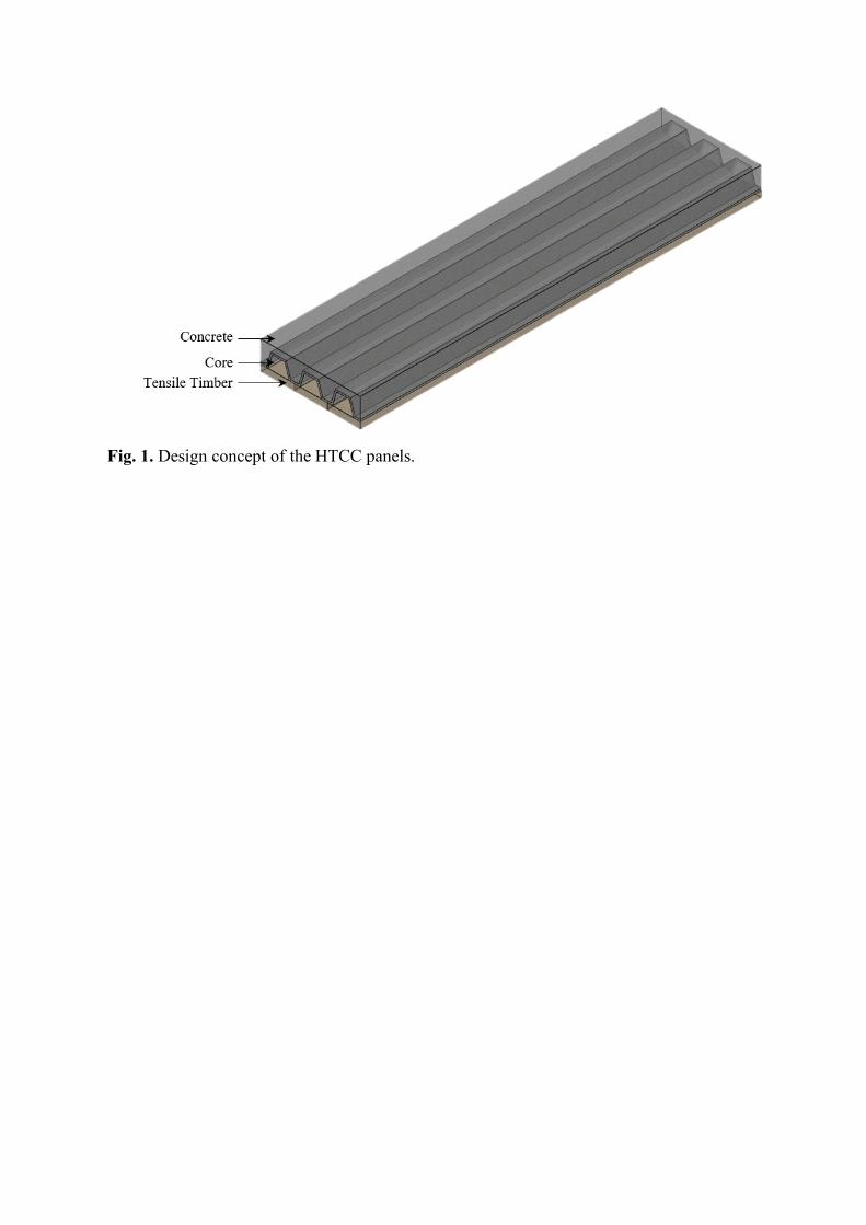
Fig. 1. Design concept of the HTCC panels.
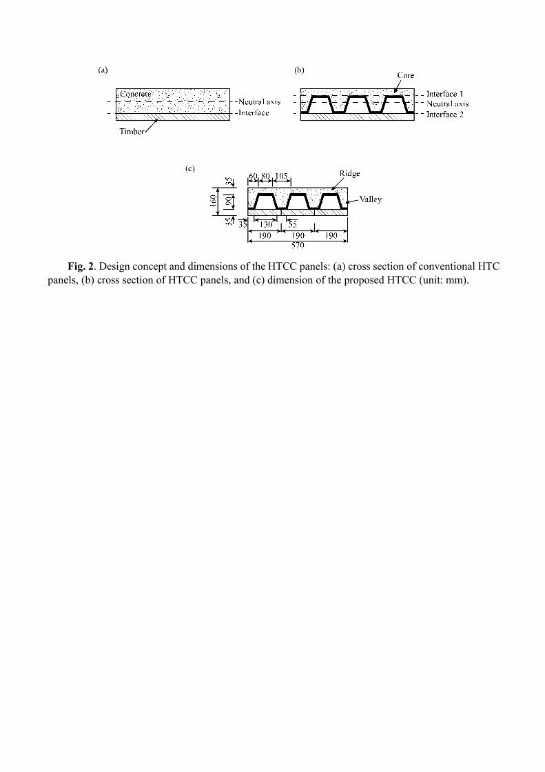
Fig. 2. Design concept and dimensions of the HTCC panels: (a) cross section of conventional HTC panels, (b) cross section of HTCC panels, and (c) dimension of the proposed HTCC (unit: mm).
Fig. 3. HTCC panel with core orientated transverse to the span.
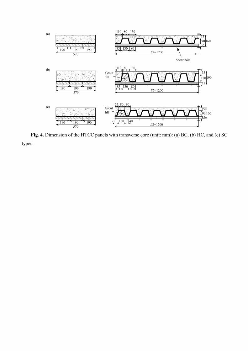
Fig. 4. Dimension of the HTCC panels with transverse core (unit: mm): (a) BC, (b) HC, and (c) SC
types.
40130l/2=1200
90 16035
35
80 9055
30190190190570
85 130l/2=1200
80
12019035
35
80 130110
190190190570
90 16035
35
80 130110
85 130l/2=1200
Shear bolt
80190190190570
(a)
(b)
(c)
Groutfill
Groutfill
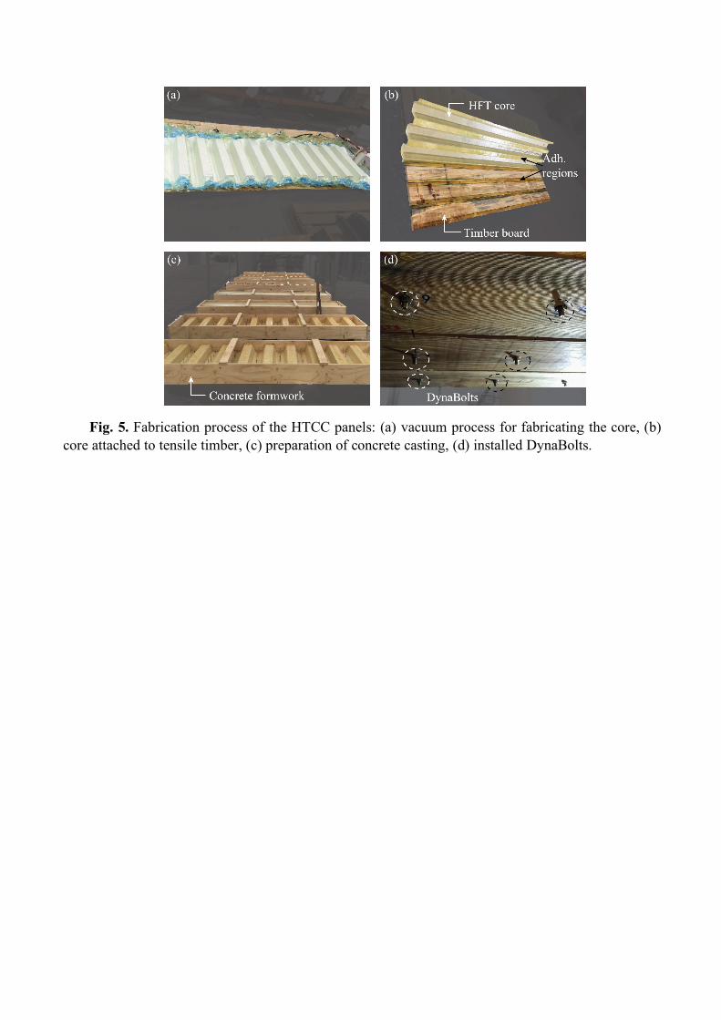
Fig. 5. Fabrication process of the HTCC panels: (a) vacuum process for fabricating the core, (b) core attached to tensile timber, (c) preparation of concrete casting, (d) installed DynaBolts.
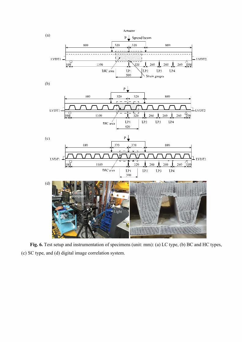
Fig. 6. Test setup and instrumentation of specimens (unit: mm): (a) LC type, (b) BC and HC types,
(c) SC type, and (d) digital image correlation system.
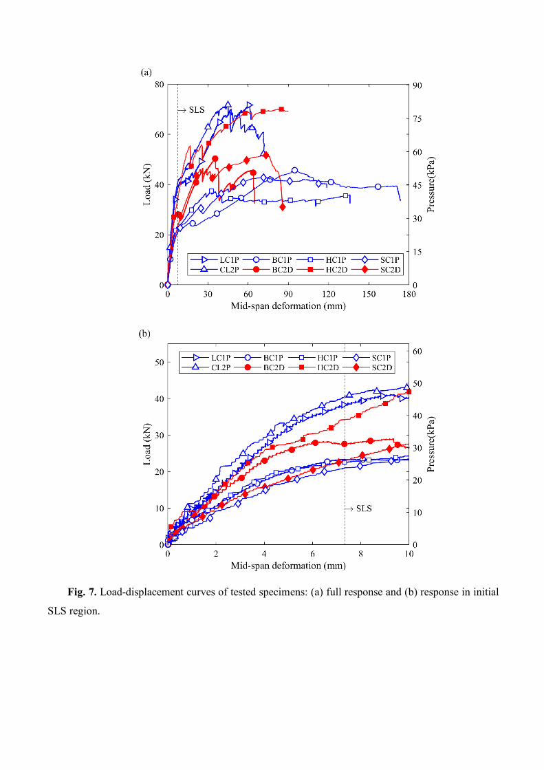
Fig. 7. Load-displacement curves of tested specimens: (a) full response and (b) response in initial
SLS region.
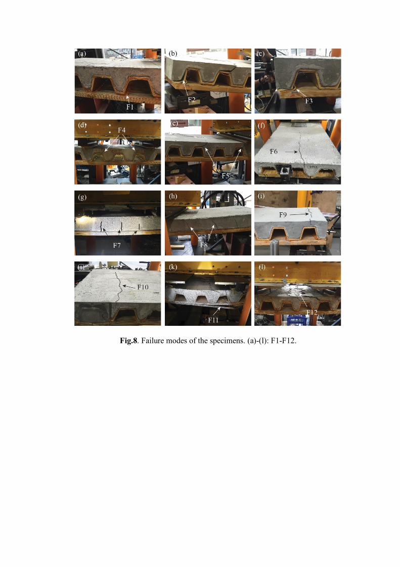
Fig.8. Failure modes of the specimens. (a)-(l): F1-F12.
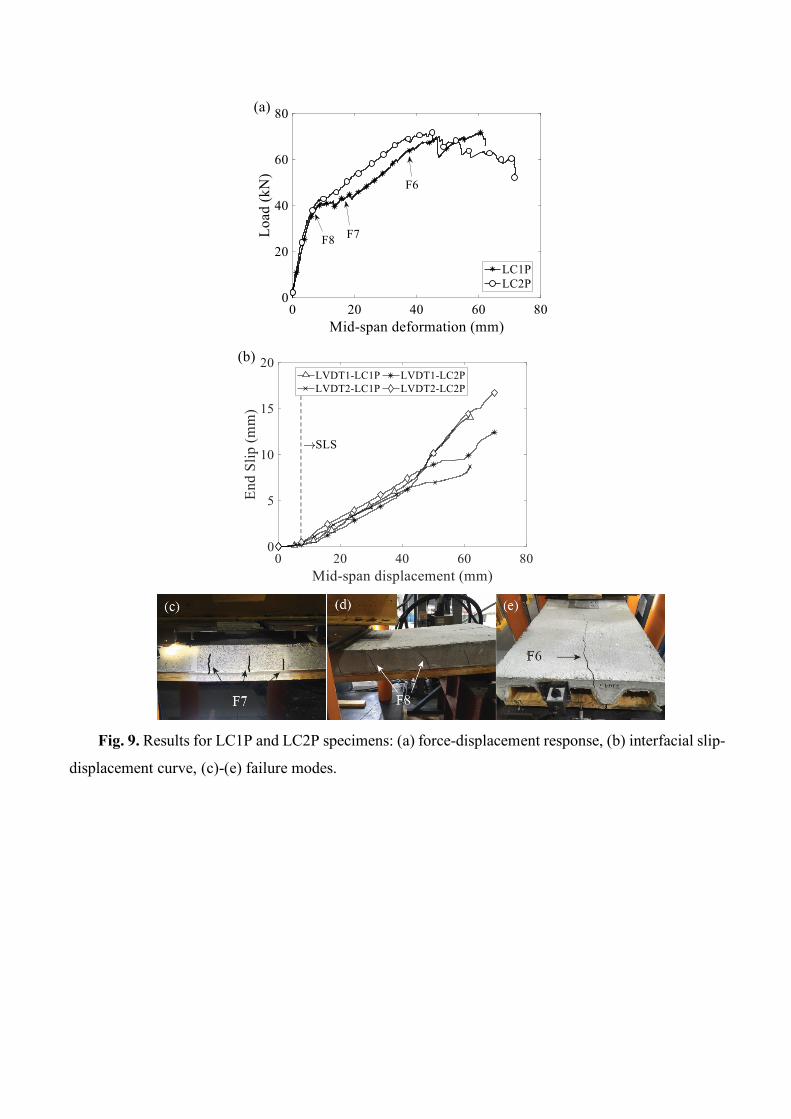
Fig. 9. Results for LC1P and LC2P specimens: (a) force-displacement response, (b) interfacial slip-
displacement curve, (c)-(e) failure modes.
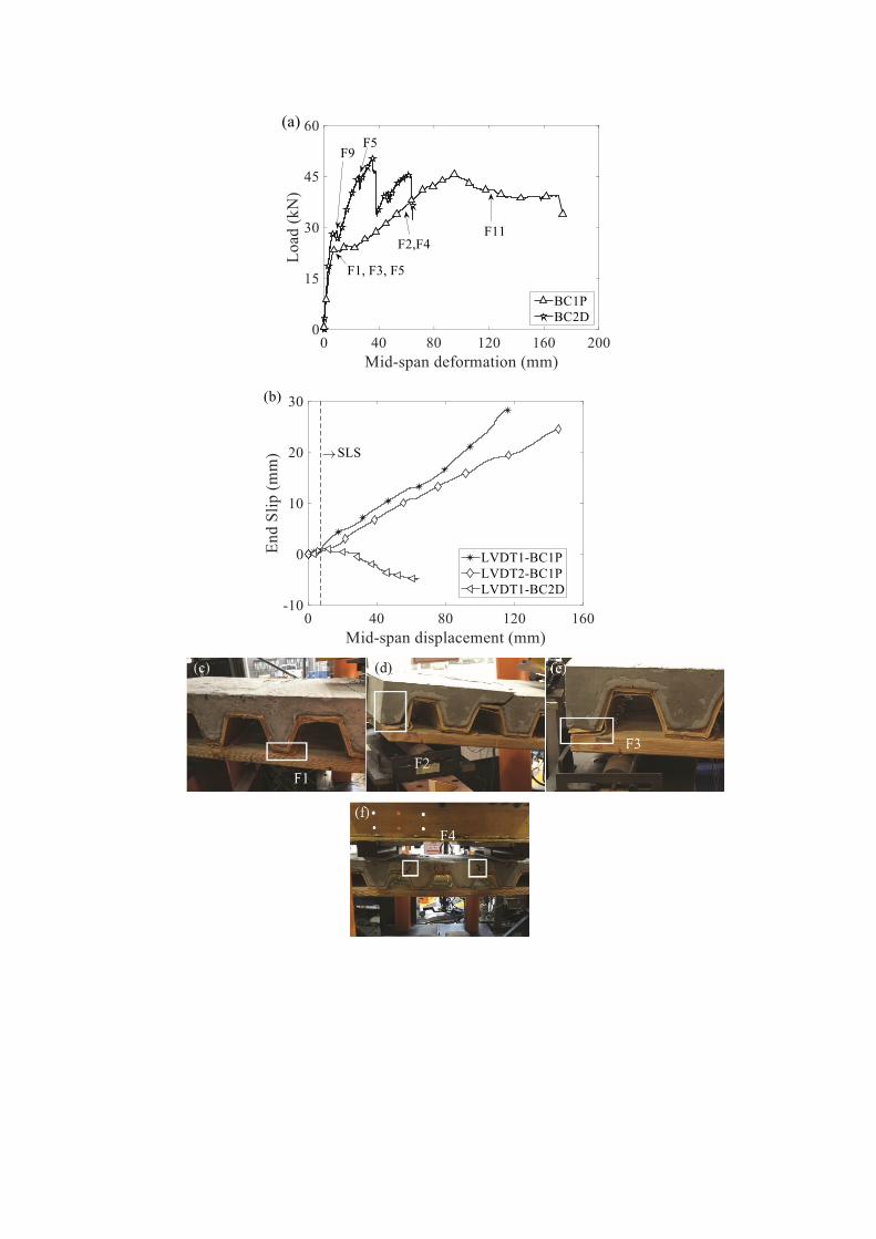
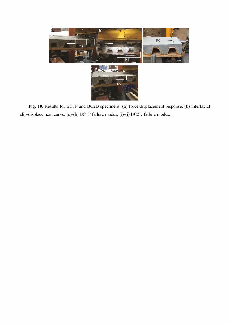
Fig. 10. Results for BC1P and BC2D specimens: (a) force-displacement response, (b) interfacial
slip-displacement curve, (c)-(h) BC1P failure modes, (i)-(j) BC2D failure modes.
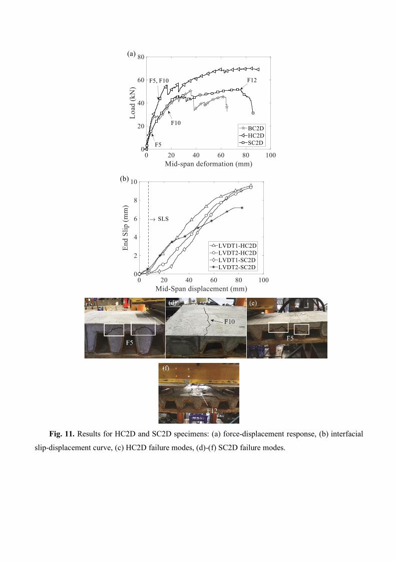
Fig. 11. Results for HC2D and SC2D specimens: (a) force-displacement response, (b) interfacial
slip-displacement curve, (c) HC2D failure modes, (d)-(f) SC2D failure modes.
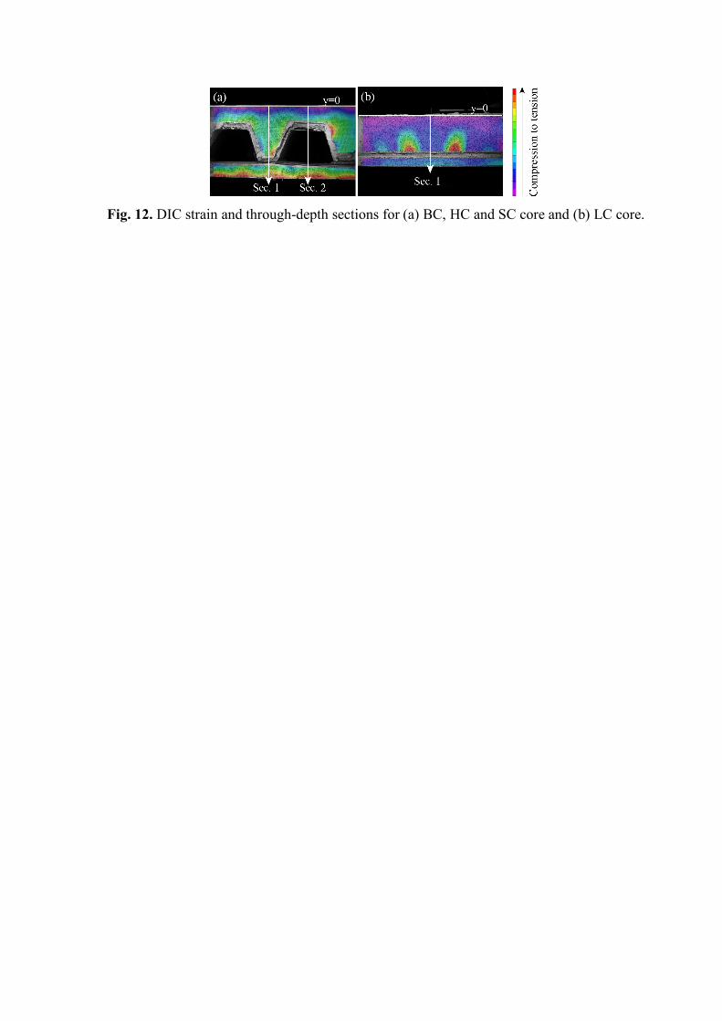
Fig. 12. DIC strain and through-depth sections for (a) BC, HC and SC core and (b) LC core.
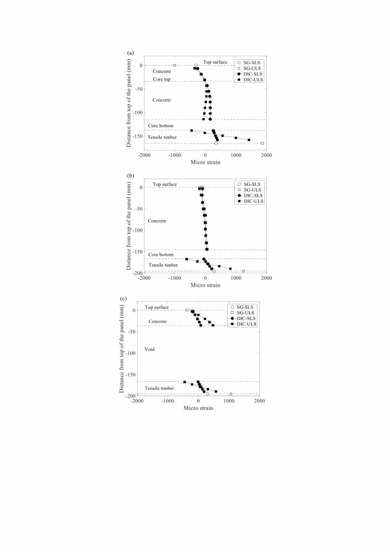
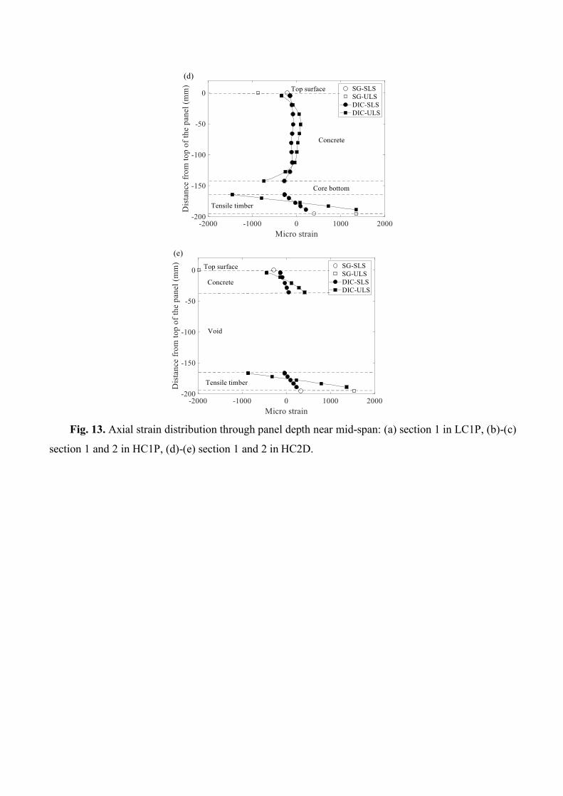
Fig. 13. Axial strain distribution through panel depth near mid-span: (a) section 1 in LC1P, (b)-(c)
section 1 and 2 in HC1P, (d)-(e) section 1 and 2 in HC2D.
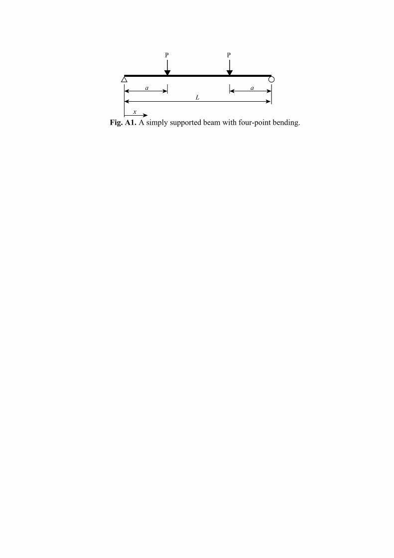
Fig. A1. A simply supported beam with four-point bending.
40
1 Fig. A2. Cross section, strain, and stress of the HTC panel section analysis. 2
3