experimental and numerical characterization of the ow and
TRANSCRIPT

Experimental and numerical characterization of the flow and heat
transfer inside corrugated pipes
Goncalo Granjal [email protected]
Instituto Superior Tecnico, Universidade de Lisboa, Portugal
November 2019
Abstract
The internal flow in corrugated tubes of different pitch, covering from the laminar to the turbulentregime, was studied in this work in order to characterize the flow and the influence of corrugationgeometry on pressure losses and heat transfer. With water as a working fluid and an imposed heat flux,a numerical model was developed with a CFD commercial software, where the k − ω SST was used tomodel turbulence. Experimental tests, where the transition region is well defined, were also developedto complement the numerical work, validating the selected flow models. Both the friction factor andthe Nusselt number increase in all corrugated tubes studied, when compared with the smooth tube,due to an induced swirl by the corrugation which also speeds the transition from laminar to turbulentflow due to separation near the corrugation region. Thermal hotspots that suggest a pulsating thermalflow are found. The thermal performance factor, which weights the increase of both pressure losses andheat transfer, is used to compare the corrugated tubes against the smooth tube, and the corrugationgeometries show a better performance. The optimal corrugated tube depends on the working flowregime. The tube with the lowest studied pitch (6 mm) shows better, yet similar, performance untilRe ≈ 2000, while it performs the worst at higher Reynolds. The tube with the highest corrugationpitch (12 mm), performs better in this regime, being an overall optimal choice if necessary to cover awide range of working points.
Keywords: Internal Flow, Corrugated Tubes, Pressure Drops, Heat Transfer, Induced Swirl, Com-putational Fluid Dynamics, Experimental setup, Turbulent regime, Laminar regime.
1. Introduction
The industries worldwide are finally realizing thenew economical and technological challenge of thecentury, energy efficiency, besides the direct in-crease in profits, it satisfies the very important en-vironmental concerns, and international organiza-tions demands, that need to be always in check toensure a sustainable planet and guarantee that fu-ture generations have a chance to exploit the sameresources. On industrial level, the coupling of thepower generation gas turbine cycle with a Rank-ine cycle, through a heat recovery steam genera-tor(HRSG), was one of the first steps to meet theenergy demand.
The concept of heat recovery system is emergingin vehicles, with the utilization of the exhaust gaseshot temperature. Various possibilities of exhaustheat recovery (EHR) are published and reviewed[1]. From the different alternatives approached inthe various revised studies, the most basic solutionappears to be the favorite, i.e. the combination ofthe internal combustion engine with a Rankine cycle
which is represented in Figure 1.
Figure 1: Basic EHR scheme adapted from Wanget al.[1]
The usage of the exhaust gases at high temper-ature, as the hot fluid inlet in a heat exchanger,allows the increase of the combined cycle efficiency,using energy that would otherwise be lost to theenvironment. This system has its largest potentialwhen applied in heavy vehicles on-road, and beingthe smallest possible is a strong condition that must
1
be complied, so that the implementation of this sys-tem can be actually beneficial. With that in mind,compact heat exchangers are used. Water is usuallythe chosen working fluid, having as a major advan-tage the fact that it is safe to use.
The efficiency of the Rankine cycle strongly de-pends on the efficiency of the heat exchanger itself,therefore, when analyzing different heat exchangers,one must take into account not only the increase inheat transfer, but also the balance between heattransfer and the power requirements. The balancebetween these factors allows the definition of thethermal performance of an heat exchanger.
The subject of increasing the efficiency in heatexchangers has been a reviewed research topic [2],being various heat transfer enhancement methodsvia induced swirl discussed, with the goal of reduc-ing the heat exchanger size and increase its per-formance. These techniques can be divided in twomajor categories, namely active and passive, de-pending weather they require or not external power.Besides the obvious advantage of not requiring anexternal power source, the passive techniques arefurther valuable as they are cost effective and eas-ily implemented in a existing heat exchanger.
Figure 2 illustrates the corrugation geometry andits characteristic dimensions, the corrugation pitch(p) and the corrugation height (e).
Figure 2: Corrugated tube schematic with charac-teristic dimensions adapted from Liu et al.[3]
A review on heat transfer enhancement[4], arguesthat the main advantages of the corrugated geom-etry are how fouling is easily removed and that theproduction cost is similar to that of a smooth tube.
A comparative work between corrugated, dim-pled and wire coils inserted tubes [5], concludes thatfor a Reynolds number higher than 2000, while theNusselt number is similar in all cases, the frictionfactor is lower in the corrugated tubes being there-fore recommended for this regime while performingthe worse in the deep laminar region.
With the spike in interest in the corrugation ge-ometry, and since there are multiple variations ofit, a literature review was made and general conclu-sions presented. Hence, heat transfer is always en-
hanced in corrugated tubes, but this enhancementis followed by an increase in the pressure drop. Therelative increase in the pressure drop of corrugatedtubes is always larger when compared to that of asmooth tube, being more relevant in the turbulentregime. The corrugation geometry, in addition tooffering a bigger wet perimeter, providing a largercontact area for heat to be transferred, also pro-duces a swirl effect on the flow that is the maincontributor to the enhancement obtained. At thesame time, it is verified that transition from lami-nar to turbulent regime occurs at earlier Reynoldsnumbers, having cases where transition occurs atRe < 1000. The work of Kareem et al. [6] alsomentions that of all the different corrugations, thehelically corrugated tubes give better enhancement.
One way to study the effect of the corrugationin a heat exchanger is to consider the thermal andhydraulic standards and compare then to the cor-rugated results, which means, comparing the heattransfer and pressure drop in the smooth circu-lar pipes with the corrugated tubes[7]. This ther-mal performance factor represents the heat trans-fer through the Nusselt number (Nu) and pressuredrop through the friction factor (f) ratios at a con-stant pumping power. It is calculated as it follows:
η =Nuc/Nus(fc/fs)1/3
(1)
Multiple correlations, that result from exper-imental studies can be found in the literature[8, 9, 10, 11, 12], although most of them are lim-ited to geometry conditions or are only valid in cer-tain regimes. Of those, however, the experimentalwork developed by Vicente et al.[9, 10], coveringboth laminar and turbulent flow, while testing tendifferent geometries with different working fluids,stands as a highly cited work in the field due to thewide range of working conditions that is covered.To classify the corrugated geometries, the authorsuse the severity index, a dimensionless parameterthat is defined with the corrugation characteristicdimensions and the hydraulic diameter (Dh):
φ =e2
pDh(2)
The friction factor correlation presented arebased on the Reynolds number (Re) calculated withthe hydraulic diameter (Dh). For the fully devel-oped laminar regime is:
f = 119.6 φ0.11Re−0.97 (3)
while the correlation suggested for the fully devel-oped low Reynolds turbulent regime (2000 < Re <8000) in low severity index (φ < 10−3) corrugationis [10]:
f = 6.12 φ0.46Re−0.16 (4)
2

as it can be seen, the above correlations for thefriction factor have a dependency on the Reynoldsnumber, like the analogous equations for thesmooth tube, the Poiseuille and Blasius equations,respectively. However, the correlations present anextra term, adding the dependence of the geometry,in the form of the severity index, to the pressuredrop.
These authors also present a general correlationregarding the Nusselt number (Nu), with Dh as thereference length in the turbulent regime:
Nu = 0.3741φ0.25(Re− 1500)0.74Pr0.44 (5)
showing the dependence of the geometry but alsothat a higher Prandtl number (Pr) will increaseheat transfer, as verified by them. This correla-tion is applicable for Re > 2000. The authors con-clude, from the analysis of pressure drop and heattransfer in both regimes, that the transition phasefrom laminar to turbulent flow occurs in a gradualsmooth way. The data also shows that the transi-tion point has a higher influence of the corrugationheight than the pitch. This influence is shown inthe critical Reynolds number correlation presented,with a 15% accuracy of set of data:
Recrit = 2100[1 + 1.18× 10⁷(e/d)3.8
]−0.1(6)
The correlation, as mentioned, is only dependenton the corrugation height and not on the corruga-tion pitch. This result gives the possibility of a bet-ter design taking in consideration that the desiredworking regime can be controlled with corrugationheight. Recently, these experimental results havebeen used by another author [13], as a validationtool for numerical simulation results, to be appliedto study the fluid behaviour and get additional in-formation to complement work that has been doneexperimentally so far.
Numerical studies have been emerging in the cor-rugation geometry, specially with the goal of opti-mizing geometry dimensions, increasing the thermalperformance ratio. Wang et al. [12] concluded intheir numerical work that in this type of geometrythe friction factor and Nusselt number are highlyinfluenced by the Reynolds number, being the ef-fect of the corrugation height higher in the pressurelosses and the corrugation pitch effect higher on theheat transfer.
2. Numerical ImplementationThe software used to solve the governing equationsin this work was Star-CCM+. This software iswidely used in engineering applications and studiesdue to the compilation of different solvers in a singlepackage, being a good choice for the current workto solve fluid flow and heat transfer and it will be
used throughout the whole study for pre-processing,solving and post-processing.
2.1. CAD domainA 3D CAD model of the corrugated tubes that willbe analyzed and used in the experimental setupwere developed with the aid of a microscopic crosssection image of the geometry. A verification of thevolume per length (m3/m) was done to guaranteethe domain input in the CFD software is valid andmatches the experimental domain. The dimensionsof the tubes, in millimeters, are presented in Ta-ble 1.
Table 1: Dimensions of the corrugated tubesDin Dout Dh p e φ
4.500 5.000 4.500 - - -4.500 5.000 4.350 12.000 0.400 0.0034.500 5.000 4.350 9.000 0.400 0.0044.500 5.000 4.350 6.000 0.400 0.006
2.2. Boundary ConditionsSince the original length is too large regarding bothcomputational performance and costs, only a peri-odic section of the corrugation is numerically simu-lated. To preserve the flow conditions, Star-CCM+allows the creation of a periodic interface that mapsa cycle with a rotation and translation. This inter-face is defined to simulate a fully developed flowand is created between two regions, the first, de-fined as a mass flow inlet in which the bulk inflowtemperature can be specified and a second, a pres-sure outlet, that together with the enclosing regiondefined with a wall boundary condition, which canhave an associated heat flux applied.
2.3. MeshingThe software has the options to generate varioustypes of meshes [14]. A polyhedral mesh, which pro-vides a balanced solution for complex mesh gener-ation problems relying on the quality of the model,besides the normal advantages it provides, has abuilt in add on called generalized cylinder that wasdeveloped to be applied in internal flows that havea mainly ruling direction, such as this case. To thischoice, it was also added to the mesh generationthe prism layer mesher option, since it generatesorthogonal prismatic cells next to wall surfaces in-creasing the accuracy of the solution in the near wallflow, making it a crucial tool to study heat transferand boundary layer phenomena (see section 2.5 fordetails).
2.4. Flow modelsIn terms of the selected models, various assump-tions were made. The working fluid was treated asan incompressible flow and its physical properties,
3

such as viscosity and conductivity, were consideredconstant. This assumption is valid for the numer-ical implementation due to the fact that the tem-perature differences throughout the study are lowsince periodic conditions are used numerically. Thegravitational force effects are neglected since previ-ous [15] studies show that the heat transfer is dueto forced convection only. A estimation of the heattransferred by radiation in this flow was made andit was considered to be negligible being two ordersof magnitude lower than all other contributions.
The Finite Volume Method is applied to the gov-erning equations (continuity and momentum) andthese can be represented in terms of a transportfactor (Φ) in a semi-discrete equation:
d
dt(ρΦV )0 +
∑f
[ρΦ(u · a)]f =
=∑f
(Γ∇Φ · a)f + (SΦV )0 (7)
where the transient term is modelled with a firstorder approximation, the convective term is com-puted with a second order upwind scheme and thediffusive term is computed with the central differ-ences scheme, being the final term, a source term.The segregated solver is used and solves the trans-port equations in the form presented above, to-gether with a pressure-velocity coupling algorithmcalled Semi-Implicit Method Pressure Linked Equa-tions (SIMPLE) [16]. For turbulence modelling, theReynolds-Averaged Navier-Stokes (RANS) are se-lected. The two-equation k − ω SST turbulencemodel, used recently for a similar problem [17], waschosen despite having a higher computational costthan the k−ε model since this model is not suitablefor swirl flows, as is this case, and buoyancy effectsnear the boundary layer [18].
2.5. Verification and ValidationA critical judgement of the simulations output mustbe performed and a certain level of confidence mustbe given. For that, the concepts of verification andvalidation have become methods that, nowadays,always go along with computational simulations.Verification is ”solving the equation right”[19] andvalidation is ”solving the right equations”[19]. Vali-dation involves the geometrical domain of the prob-lem, its boundary conditions and properties, aswell as, the model assumptions taken to simplifythe simulation and its cost. Therefore, a previousknowledge of the modelled case is required and ex-tensive experimental data is required to fully vali-date a CFD model and its solution.
A grid independence study was made for eachdifferent geometry. The meshes base size and itsnumber of cells, for each geometry, are shown be-low in Table 2. It should also be mentioned that
the prism layer thickness was kept constant in therefinements.
Table 2: Generated meshes for the grid indepen-dence study
Base Size φ= 0.003 φ = 0.004 φ = 0.006
2.00E-04 32200 36898 51043
1.50E-04 85125 80718 114156
1.00E-04 241592 191578 298944
7.50E-05 639438 373717 504601
5.00E-05 1251552 842245 810102
4.00E-05 1824321 1291354 -
2.50E-05 - 2072197 -
Figure 3 shows an example of the generatedmeshes in a cross section, where is visible the poly-hedral cells mesh and the prism layer mesh, anda mid section view, where the generalized cylindermodel can be observed in the direction of the flow.
(a) Cross section view
(b) Mid section view
Figure 3: Example of the generated meshes
The studies were performed with periodic con-ditions over one period (pitch) of the geometry inquestion, the boundary conditions were the samefor all simulations and domains, throughout the dif-ferent meshes, important quantities were monitoredbesides the equations residuals, the mass flow at theoutlet, the Nusselt number and the friction factor.The grid independence study for a mass flow in-put that corresponds to Reynolds number of 1300is presented in Figure 4.
4

Figure 4: Friction factor grid independence studyfor Re = 1300 and tubes with different severity in-dex
It is noticeable that from a certain mesh, arounda cell count of 1.2 million cells for geometry φ =0.003 and φ = 0.004 and a cell count of 300k cellsfor geometry φ = 0.006, there is not a relevant dif-ference between the obtained results and further re-finements, being that, the last refined meshes, gavea different in percentage, when compared with theprevious mesh, for the friction factor of less than0.5% for all geometries. Consequently, it can beconcluded that the results are grid independent andare converged.
As a benchmark case, the smooth tube was con-sidered, with the aforementioned models, and theobtained results were compare with those reportedin the literature [20]. Furthermore a complete ex-perimental study was also performed in this workto fully validate the numerical models and the ob-tained results with the geometries in which theCAD models were based, providing a good matchbetween the numerical and experimental work.
3. Experimental workThe base setup used in this work was previouslyused and validated [21], being adapted and preparedto fit the purpose of this work and complement thenumerical study. The experimental setup is repre-sented, schematically, in Figure 5.
Figure 5: Experimental setup schematic overview
A magnetically coupled vane pump (1) is used
to apply pressure to the working fluid for it toflow throughout the experimental setup. The pumpspeed, which regulates the mass flow, is controlledwith a frequency converter. Valve (2) is used to aidin the regulation of the desired flow. So, when itis opened, it splits the flow rate, forcing the work-ing fluid to recirculate back to the reservoir (8).Valve (3) has a similar function and it is also usedto regulate the flow rate. In order to make sure theflow rate is adequate, a Coriolis mass flow meter (4)reads the mass flow rate and the density of the fluidupstream of the valves. A platinum resistance ther-mocouple is also installed in the mass flow meter,allowing a measurement of the fluid temperature,this thermocouple with the aid of the cooling sys-tem (7) are of great importance since they providea constant control of the working fluid inlet temper-ature. The development section (5) is constructedof a smooth tube. The length of the smooth devel-opment section is around 720 mm. The test section(6) is 780 mm long and it can be made with any ofthe tube geometries. After passing the test section,the working fluid then goes through a mixing sys-tem where it can be cooled (7) before returning tothe reservoir and therefore closing the experimentalloop.
A more focused detailed view of test section (6)is represented, schematically, in Figure 6. The testsection, is heated by Joule effect, using a DC powersupply, providing a constant heat flux applied to thetube walls that is measured on the tube test sectionitself, accounting for the dissipated heat throughthe conductive cables, in order to ensure minimalheat loses to the ambient air, all the tubes thatmake the test section are insulated with rubber.
To analyse the pressure drop along the test sec-tion, two pressure sensors connected to a differentialpressure transducer were installed as shown in thefigure. The first (∆P1), measures the pressure dropfrom the the inlet of the test section to the outlet,which represents a length of 780 mm, the second(∆P2), measures the pressure drop from the lastthird of the test section to the outlet of it. Thepressure sensors have a precision of ±0.25% andthe Taylor and Kuyatt [22] uncertainty analysis wasperformed.
Along the test section, four type K thermocou-ples were installed with a even distance betweeneach other, providing not only the surface temper-ature of the tube in four different locations (Ts1 toTs4), but also a good qualitative information on thesurface temperature evolution along the tube. Be-sides this, two type K thermocouples were also in-stalled with the goal of evaluating the average fluidtemperature, one in the inlet (Tin), adding to thetemperature measured in the mass flow meter, andanother in the outlet (Tout). Since problems were
5

found in previous works when measuring the outlettemperature, a mixing chamber is added at the out-let, where the outlet temperature is actually beingmeasured, the mixing of the fluid, will improve theaccuracy of the measurement of the average fluidtemperature at the outlet, having the used thermo-couples a uncertainty of ±0.1%K.
Figure 6: Test section scheme zoom representation
4. Results
4.1. ValidationThe experimental setup is firstly validated with asmooth tube and the literature correlations for thisgeometry [20]. The friction factor for both regimesmatched well with a average relative error of lessthan 12.5%. For the Nusselt number, this averagerelative error is less than 10%.
With the experimental setup validated it can beused to validate and complement the numerical re-sults. To avoid presenting repeated data, the ex-perimental and numerical results are presented to-gether below in Figures 11 and 12. It can be in-ferred that the different source results match wellbeing the taken numerical assumptions and modelsvalidated for internal flows in this type of geometry.
4.2. Flow CharacterizationFigure 7 presents the tangential component of ve-locity, represented by a cross section scalar view anda PDF volume distribution of said velocity. Theeffects of the corrugation in the tangential compo-nent of the velocity are way more significant thanin the radial component. As it can be seen, the in-duced tangential component of the velocity swirlsaround the tube walls to towards the corrugation.This component relevance in the flow is noticed bythe fact that its maximum magnitude is 10% of theaxial component magnitude, adding to the uniformpresence of this velocity component in all of thegeometric volume as it can be seen from the PDFdistribution.
This result shows a key feature of this geometry:the tangential velocity created by the corrugation,induces a swirl in the flow that will promote a heattransfer increase.
The corrugation geometry advances the transi-tion of the flow from laminar to turbulent shiftingit to lower Reynolds numbers. Regardless, thereis a more relevant finding in this work: the results
(a) Cross section view (b) PDF velocity distribution
Figure 7: Tangential velocity scalar scene and PDFdistribution
suggest that the transition depends only on the cor-rugation height. With the aim of providing a deeperanalysis on the flow characterization and better sus-tain these arguments, the velocity vectors close tothe wall in a mid section plane of the geometry forthe laminar regime near the transition region (Re= 500) are presented in Figure 8.
Figure 8: Velocity vectors for Re = 500
Following this, it becomes relevant to describethe flow in this region, in the turbulent regime,as depicted in Figure 9. Analogously to Figure 8,it presents the velocity field near the corrugationheight, but in this case in the turbulent regime (Re= 2100). From this figure it can be noticed thatthe separation which occurs in the region of thecorrugation and propagates, causing a recirculatingzone, which can be identified from the velocity vec-tors orientation that connects to the next geometryperiod.
Figure 9: Velocity vectors for Re = 2100
This analysis shows the relevance of the corruga-tion height in the flow and how this design dimen-sion can be used to control the transition region andconsequently the working regime for a desired massflow.
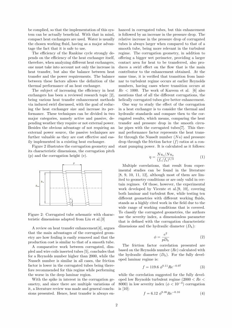
Figure 10 shows the Nusselt number distributionon the tube wall. It presents the lowest Nusseltnumber in the corrugation depth and the highest
6
in the zone after it, which is related with the re-circulation zone that the corrugation induces in theturbulent regime and that follows the corrugationpath along the pitch. The Nusselt variation alongthe periodic domain of the flow provides the impor-tant understanding that the flow is thermally pul-sating. Also, this Nusselt variation is important inthe design of the tube as it identified the hotspots(i.e. regions of lower Nusselt).
Figure 10: Turbulent Nusselt number distributionat tube wall Re = 2100
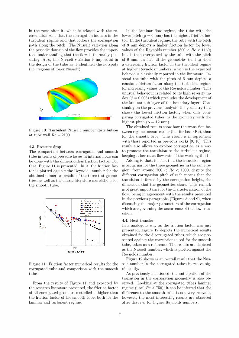
4.3. Pressure dropThe comparison between corrugated and smoothtube in terms of pressure losses in internal flows canbe done with the dimensionless friction factor. Forthat, Figure 11 is presented. In it, the friction fac-tor is plotted against the Reynolds number for theobtained numerical results of the three test geome-tries, as well as the classic literature correlations forthe smooth tube.
Figure 11: Friction factor numerical results for thecorrugated tube and comparison with the smoothtube
From the results of Figure 11 and expected bythe research literature presented, the friction factorof all corrugated geometries studied is higher thanthe friction factor of the smooth tube, both for thelaminar and turbulent regime.
In the laminar flow regime, the tube with thelower pitch (p = 6 mm) has the highest friction fac-tor. In the turbulent regime, the tube with the pitchof 9 mm depicts a higher friction factor for lowervalues of the Reynolds number (800 < Re < 1150)but is then overpassed by the tube with the pitchof 6 mm. In fact all the geometries tend to showa decreasing friction factor in the turbulent regimeat higher Reynolds numbers, which is the expectedbehaviour classically reported in the literature. In-stead the tube with the pitch of 6 mm depicts aconstant friction factor along the turbulent regimefor increasing values of the Reynolds number. Thisunusual behaviour is related to its high severity in-dex (φ = 0.006) which precludes the development ofthe laminar sub-layer of the boundary layer. Con-tinuing on the previous analysis, the geometry thatshows the lowest friction factor, when only com-paring corrugated tubes, is the geometry with thehighest pitch (p = 12 mm).
The obtained results show how the transition be-tween regimes occurs earlier (i.e. for lower Re), thanfor the smooth tube. This result is in agreementwith those reported in previous works [9, 10]. Thisresult also allows to explore corrugation as a wayto promote the transition to the turbulent regime,keeping a low mass flow rate of the working fluid
Adding to that, the fact that the transition regionis occurring for the three geometries in the same re-gion, from around 700 < Re < 1000, despite thedifferent corrugation pitch of each means that thetransition is forced by the corrugation height, thedimension that the geometries share. This remarkis of great importance for the characterization of theflow, being in agreement with the results presentedin the previous paragraphs (Figures 8 and 9), whendiscussing the major parameters of the corrugationwhich are governing the occurrence of the flow tran-sition.
4.4. Heat transferIn a analogous way as the friction factor was justpresented, Figure 12 depicts the numerical resultsobtained for the 3 corrugated tubes, which are pre-sented against the correlations used for the smoothtube, taken as a reference. The results are depictedas the Nusselt number, which is plotted against theReynolds number.
Figure 12 shows as an overall result that the Nus-selt number in the corrugated tubes increases sig-nificantly.
As previously mentioned, the anticipation of thetransition in the corrugation geometry is also ob-served. Looking at the corrugated tubes laminarregime (until Re < 750), it can be inferred that thedifference to the smooth tube is not very relevant,however, the most interesting results are observedafter that i.e. for higher Reynolds numbers.
7

Figure 12: Nusselt number results for the corru-gated tube and comparison with the smooth tube
When the flow enters the transition/early turbu-lent region (750 < Re < 2000) in the corrugatedtubes, for that same mass flow, the flow is still lam-inar in the smooth tube. Consequently the convec-tive heat transfer coefficients (made dimensionlessthrough the Nusselt number) are much higher thanthose of the smooth tube, although these differencesare mainly due to the regime transition. The high-est Nusselt number is again observed for the geom-etry with the lowest corrugation pith of 6mm andhighest severity index, as the effect in the thermalboundary layer is similar to that described in theprevious paragraphs.
Looking at the turbulent regime from aroundRe ≈ 3000, it can be noticed that while the corru-gated tubes continue to present an increased Nus-selt number against the smooth tube, the corru-gated tube with the lowest severity index and high-est pitch (12 mm) appears, barely, as the geometrywith the highest Nusselt number.
The geometry with the intermediate pitch (9mm) appears as the middle term geometry for thelower Reynolds and at the last point presented inthis figure shows a tendency to increase for higherReynolds.
This analysis shows that depending on the de-sired mass flow, and consequently flow regime, forthe same corrugation height, the pitch plays an in-teresting role in terms of heat transfer, for lami-nar/low turbulent Reynolds: the lowest pitch pro-motes heat transfer while for higher Reynolds, thehighest pitch appears to be the best option whenlooking at the capacity of the tube to transfer en-ergy.
5. Thermal performance factor
Another important analysis is to compare the dif-ferent corrugation geometries between each other,through a parameter that takes into account the
friction factor and the Nusselt number, allowingthe discussion of an optimal solution which balancesthese two opposite effects.
Figure 13 presents the thermal performance ofthe three different corrugated geometries testedwith the different flow regimes identified allowinga complete analysis of the value of using corrugatedin heat exchanger applications, as well as the com-parison between the corrugated tubes themselves,due to the different corrugation pitches that weretested.
Figure 13: Thermal performance factor of the var-ious corrugated geometries calculated with the nu-merical results
As a first analysis, the thermal performance of thecorrugated tubes clearly surpasses the performanceof the smooth tube. Since the thermal performancethat is being analyzed is performance of just thetubes, not an entire heat exchanger, and that thisfactor clearly prioritizes the increase of heat transferover the increase in the pressure drops, all threecorrugated geometries perform, as expected, betterthan the smooth tube.
The behaviour of the thermal performance of thethree geometries is similar, increasing until a max-imum thermal performance and then presenting arelatively constant value. As it was already men-tioned the transition region is anticipated so thattransition occurs for lower Reynolds numbers in thecorrugated tubes than in the smooth tube. Thisexplains the thermal performance evolution as itreaches the maximum value just after the transi-tion region of the corrugated tube. This maximumthermal performance zone is explained to be nearthe transition/early turbulent region (Re < 2000)since in this region, while the corrugated flow is al-ready presenting turbulent heat transfer and pres-sure drop values, the flow in the smooth tube, forthe same Reynolds number, would still be laminar,being this flow regime difference of great impor-tance in the thermal performance, since more heat
8

can be transferred in the turbulent regimes and, inthe case of the corrugated tube, this can be achievedwith a lower mass flow requirement.
Overall, all corrugated tubes perform similarlyuntil Re ≈ 2000, despite the tube with the highestseverity index being the best of the three. How-ever, for higher Reynolds this tube performs theworst and, from the behaviour of figure 11 this trendseems to continue since the friction factor appearsalmost constant with the increase in the Reynolds.Therefore, to cover the entire tested range, andextrapolating with the tendency for higher massflow values, the tube that is recommended fromthe three is the tube with the lowest severity in-dex (φ = 0.003) and highest corrugation pitch (p = 12mm).
6. ConclusionsThe work developed in this thesis had as a main goalthe characterization of the internal flow in corru-gated tubes both hydrodynamically and thermally,with an applied heat flux. Three different corru-gated geometries were modelled and simulated us-ing a commercial CFD software and a experimentalsetup, adapted from previous work [21], was used totest those corrugated geometries, as a comparisonand validation tool, and a smooth tube for validat-ing the experimental setup itself.
The main conclusions of this work can be sum-marized as it follows:
• The numerical chosen models were successfullyvalidated with the experimental results.
• The experimental results on the friction factorclearly show that the transition region is an-ticipated for the corrugated tubes, comparingto the smooth tube. However, the transitionReynolds values are approximately the samefor the various geometries. Further analysis tothe flow characteristics, based on the numericalresults suggests that the transition is governedsolely by the corrugation height.
• The 3D components of the velocity and theirinfluence is studied, with the demonstrationthat the tangential velocity induces a swirl ef-fect on the flow.
• The heat transfer distribution on the wall isshown, through the Nusselt number. For thelaminar regime, this distribution is relativelyeven, but in the turbulent regime, a gradientis noticeable which can be used for design pur-poses, since the low Nusselt number zones iden-tify the hot spots in the tubes.
• The corrugated geometry increases both thefriction factor as the Nusselt number, averag-
ing an increase around 4 times in both factorswhen compared to the smooth tube.
• The thermal performance factor shows that thebest performer of the three geometries dependson the working flow regime, being the low-est pitch geometry recommended for the lam-inar/transition regime and the highest pitchtube recommended for the turbulent regime.
• The transition region and the start of the tur-bulent regime show the best performance forworking points and a heat exchanger shouldbe designed for these mass flow rates.
• Overall, to cover a wide range of workingpoints, based on performance, the highest pitchgeometry is recommended.
For future research, with the complete validationof the numerical models used, a study is suggested,where the corrugation height is changed to confirmthe preliminary results shown here (e.g. the dom-inance of the corrugation height to promote theoccurrence of flow transition). Furthermore, addi-tional geometric features could be explored, suchas the curvature and the inclination angle of thecorrugation. Afterwards, the entire heat exchangerperformance should be evaluated, to infer on theutility of the extrapolation of the results discussedin this work. Finally, it is suggested to use a dou-ble goal optimization algorithm in the corrugatedgeometry with the intent of maximizing the heattransfer with the least pressure losses possible.
References[1] Tianyou Wang, Yajun Zhang, Zhijun Peng,
and Gequn Shu. A review of researches onthermal exhaust heat recovery with Rankinecycle. Renewable and Sustainable Energy Re-views, 15(6):2862–2871, 2011.
[2] Mohsen Sheikholeslami, Mofid Gorji-Bandpy,and Davood Domiri Ganji. Review of heattransfer enhancement methods: Focus on pas-sive methods using swirl flow devices, sep 2015.
[3] Lin Liu, Xiang Ling, and Hao Peng. Analy-sis on flow and heat transfer characteristics ofEGR helical baffled cooler with spiral corru-gated tubes. Experimental Thermal and FluidScience, 44:275–284, 2013.
[4] Wen Tao Ji, Anthony M. Jacobi, Ya Ling He,and Wen Quan Tao. Summary and evalua-tion on single-phase heat transfer enhancementtechniques of liquid laminar and turbulent pipeflow. International Journal of Heat and MassTransfer, 88:735–754, 2015.
9

[5] A. Garcıa, J. P. Solano, P. G. Vicente, andA. Viedma. The influence of artificial rough-ness shape on heat transfer enhancement: Cor-rugated tubes, dimpled tubes and wire coils.Applied Thermal Engineering, 35(1):196–201,2012.
[6] Zaid S Kareem, M N Mohd Jaafar, Tholudin MLazim, Shahrir Abdullah, and Ammar F Ab-dulwahid. Passive heat transfer enhancementreview in corrugation. Experimental Thermaland Fluid Science, 68:22–38, 2015.
[7] Hamed Sadighi Dizaji and Samad Jafarmadar.Experiments on New Arrangements of Con-vex and Concave Corrugated Tubes througha Double-pipe Heat Exchanger. ExperimentalHeat Transfer, 29(5):577–592, 2016.
[8] S. Pethkool, S. Eiamsa-ard, S. Kwankaomeng,and P. Promvonge. Turbulent heat transfer en-hancement in a heat exchanger using helicallycorrugated tube. International Communica-tions in Heat and Mass Transfer, 38(3):340–347, 2011.
[9] P.G. Vicente, A. Garcia, and A. Viedma.Mixed convection heat transfer and isothermalpressure drop in corrugated tubes for laminarand transition flow. International Communi-cations in Heat and Mass Transfer, 31(5):651–662, jul 2004.
[10] P. G. Vicente, A. Garcia, and A. Viedma. Ex-perimental investigation on heat transfer andfrictional characteristics of spirally corrugatedtubes in turbulent flow at different Prandtlnumbers. International Journal of Heat andMass Transfer, 47(4):671–681, feb 2004.
[11] Wei Wang, Yaning Zhang, Yongji Li, HuaizhiHan, and Bingxi Li. Numerical study on fully-developed turbulent flow and heat transfer ininward corrugated tubes with double-objectiveoptimization. International Journal of Heatand Mass Transfer, 120:782–792, may 2018.
[12] Wei Wang, Yaning Zhang, Yongji Li, HuaizhiHan, and Bingxi Li. Multi-objective optimiza-tion of turbulent heat transfer flow in noveloutward helically corrugated tubes. AppliedThermal Engineering, 138:795–806, jun 2018.
[13] J. I. Corcoles-Tendero, J. F. Belmonte, A. E.Molina, and J. A. Almendros-Ibanez. Numer-ical simulation of the heat transfer process ina corrugated tube. International Journal ofThermal Sciences, 126:125–136, apr 2018.
[14] Hakki Karakas, Emre Koyuncu, and GokhanInalhan. ITU tailless UAV design. Journal of
Intelligent and Robotic Systems: Theory andApplications, 69(1-4):131–146, 2013.
[15] Filipe Arruda Andrade. Caracterizacao Exper-imental da Transmissao de Calor em Escoa-mentos no Interior de Tubos Corrugados, 2018.
[16] S. V. Patankar. Numerical heat transfer andfluid flow. CRC Press, 1980.
[17] J. Hærvig, K. Sørensen, and T. J. Condra.On the fully-developed heat transfer enhancingflow field in sinusoidally, spirally corrugatedtubes using computational fluid dynamics. In-ternational Journal of Heat and Mass Transfer,106:1051–1062, 2017.
[18] K. Hanjalic. One-Point Closure Models forBuoyancy-Driven Turbulent Flows. AnnualReview of Fluid Mechanics, 2002.
[19] P. J. Roache. QUANTIFICATION OF UN-CERTAINTY IN COMPUTATIONAL FLUIDDYNAMICS. Annual Review of Fluid Mechan-ics, 1997.
[20] Frank P Incropera, David P DeWitt,Theodore L Bergman, and Adrienne SLavine. Fundamentals of Heat and MassTransfer 6th Edition. Wiley, 2007.
[21] A. Nikulin, A. S. Moita, A. L.N. Moreira,S. M.S. Murshed, A. Huminic, Y. Grosu,A. Faik, J. Nieto-Maestre, and O. Khliyeva. Ef-fect of Al2O3 nanoparticles on laminar, tran-sient and turbulent flow of isopropyl alcohol.International Journal of Heat and Mass Trans-fer, 130:1032–1044, 2019.
[22] Barry N Taylor and Chris E Kuyatt. Guide-lines for Evaluating and Expressing the Uncer-tainty of NIST Measurement Results. NISTTechnical Note, 1994.
10