experimental analysis of propagation of plastic …
TRANSCRIPT
T H E A R C H I V E O F M E C H A N I C A L E N G I N E E R I N G
VOL. LIX 2012 Number 4
10.2478/v10180-012-0021-2Key words: mechanics of solids, experimental methods, elastic-plastic states
BARBARA KOZŁOWSKA ∗
EXPERIMENTAL ANALYSIS OF PROPAGATION OF PLASTICZONES IN TWO-DIMENSIONAL PROBLEMS
In the paper, the author presents experimental analysis of propagation of plasticzones in two-dimensional models with different stress concentrators. The experi-mental tests were carried out by photoelastic coating method on duralumin stripesloaded by tensile stresses. For various levels of loading, the photographs of isochro-matic pattern were taken under loading and after removing loading. On the basisof isochromatic pattern recorded for loaded models, the boundaries of plastic zoneswere determined using the Treska-Coulomb yield condition. The isochromatic patterntaken for the unloaded, but previously partly plastified elements, show the picture ofthe residual strain remaining in the material. A discussion of the results is presented.
1. Introduction
The development of modern technology allows for more economic useof the constructional material. It is connected with common acceptation ofsmall, local plastic deformation in elements working in the range of thelimited fatigue strength. That is why the analysis of elastic-plastic strainstates has many important applications in engineering design.
In general, the quantitative analysis of strain and stress in the plastifiedzones concerns any object working in over-elastic range. It is necessary todistinguish, however, some specific elastic-plastic problems, which are impor-tant, from the practical point of view, e.g. determining the bearing capacityof elements or the analysis of residual strain.
Determining the bearing capacity of the element means, strictly speaking,finding the value of loading level, for which one of its cross-sections becomescompletely plastified, and the element is losing its usefulness as a part of thestructure. It is, in many cases, difficult, especially for elements of complicated
∗ Warsaw University of Technology, Faculty of Mechatronical Engineering, ul. Św. An-drzeja Boboli 8, 02-525 Warsaw, Poland; e-mail: [email protected]

398 BARBARA KOZŁOWSKA
shapes and subjected to complex loading. Therefore, nowadays the extremeprinciples of the theory of elasticity are applied, which make it possible tofind upper and lower estimation of bearing capacity. The lower estimation ofbearing capacity can be found by assuming, in the analyzed area, a staticallyadmissible stress field. The upper estimation of bearing capacity can beobtained by accepting any, kinematically admissible mechanism of elementsfailure.
The acceptance of partial plastifying of material in constructional ele-ments during exploitation causes the necessity of solving nonlinear problems.In such cases, even extensively developed and widely used, numerical meth-ods can not assure full and reliable result due to modeling problems. Toverify numerical calculation and to supply information for hybrid methods,experimental testing is very useful [14].
Experimental investigation of bearing capacity concerns solving typical,technical problems, like testing of point welds [18, 17] or railway carriageframes [12]. It may also concern, in more general sense, the analysis ofpropagation of plastic zones created around stress concentrators (holes andnotches) [4, 5, 11]. Their uncontrolled expansion can conduce to elementsfailure.
Bearing capacity problems are often associated with elastic-plastic in-vestigations from the domain of cracking mechanics or low-cyclic fatigue.They concern, for example, the analysis of plastic zones developing nearbya crack in a slot bottom [13, 16].
Another important problem of elastic-plastic analysis is the assessmentof residual (plastic) strain existing in unloaded material after its previousloading over yield point. The experimental investigations in this field con-cern testing the mechanical properties of constructional materials which canchange as the result of the residual strain [3]. They could also be appliedto the exploitation investigation of actual structures [1] and the analysis ofresidual strain cumulation under cyclic loading [2, 20].
2. Experimental testing
2.1. Method of photoelastic coating
One of the experimental methods, which can be applied to the analysis ofelastic-plastic states, is the photoelastic coating method. This method givesinformation about the deformation of the real object in the whole tested area(not only at several points) and can be used to investigate objects of complexshapes and loaded in different ways, also in the over-elastic range of material.
EXPERIMENTAL ANALYSIS OF PROPAGATION OF PLASTIC. . . 399
The photoelastic coating method makes use of the effect of the opticalbirefringence which occurs in some transparent materials under loading [19].It is based on the assumption that there is univocal dependence between thestrain occurring on the surface of the analyzed element and the deformationof the thin layer of birefringent material integrally bonded to this surface.When the object is loaded, the surface strains are transmitted to the coating,which may be observed through a reflection polariscope. In that case, loadedcoating exhibits two families of fringe patterns: isoclinic fringes providinginformation about directions of principal strains, and isochromatic fringessupplying information about the difference of principal strains.
The method of photoelastic coating can be applied to the elastic-plasticstates analysis, because of the linear relation between the photoelastic effectand strain in the birefringent materials, valid in a wide range. In the range ofstrain where the material of the constructional element is already plastified,the characteristic of photoelastic coating material is still linear.
The information obtained from the photoelastic coating method is notsufficient for determining all strain components in general case of two-dimensional state of stress occurring on the surface of the investigated object.Besides, the measurement of isoclinic parameter is labour-consuming andusually not precise. Therefore, to make the analysis of full strain state, oneoften uses additional information obtained from other experimental methodsor from analytical (or numerical) calculations.
The examples of determining the strain and stress values in elastic-plasticareas around stress concentrators in two-dimensional models can be found inanother paper by the author [10]. For strain separation on the basis of isochro-matic pattern only, the author applied the analytical method of characteristics,and the strain and stress components were calculated using multi-sectionalschematization of the material (σ-ε) curve [6].
The most important advantage of the method, especially with referenceto the investigation of creation and development of plastic zones, is an ex-cellent visualization and possibility of direct observation of the progressingplastifying process.
2.2. Models of constructional elements
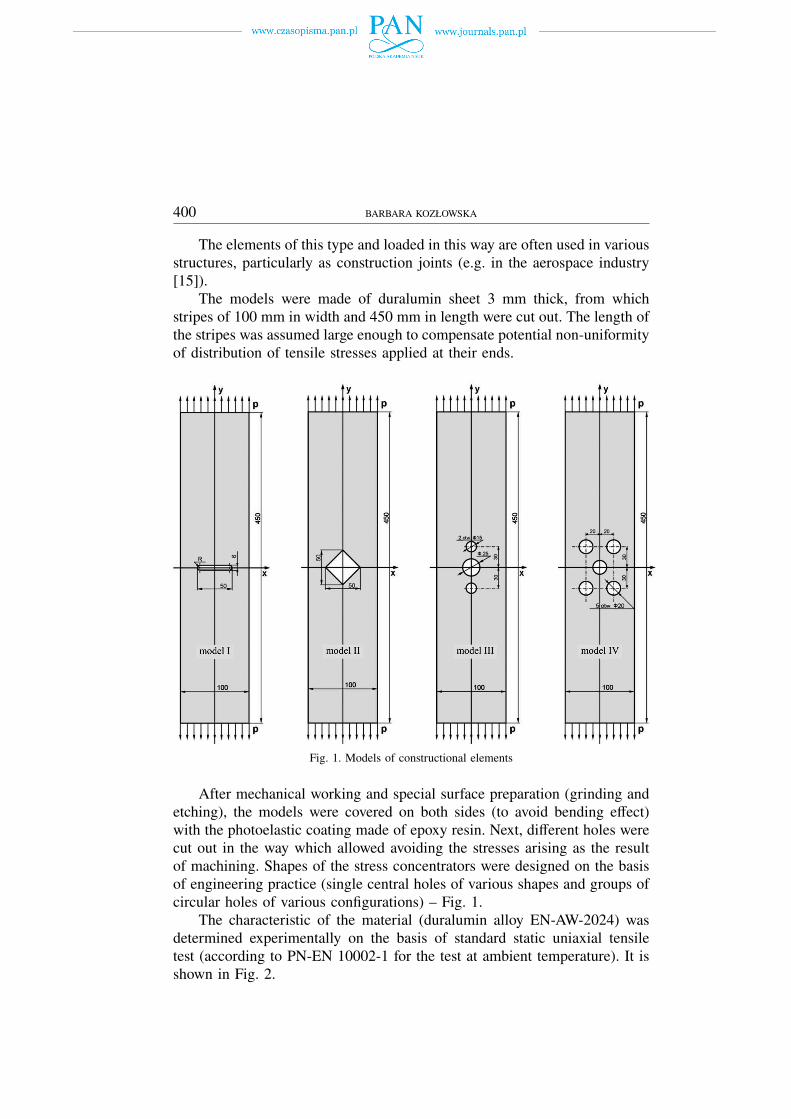
The investigation of propagation of plastic zones by photoelastic coatingmethod was performed on two-dimensional models of constructional ele-ments weakened by different stress concentrators (holes) and subjected totensile stresses – Fig. 1.
400 BARBARA KOZŁOWSKA
The elements of this type and loaded in this way are often used in variousstructures, particularly as construction joints (e.g. in the aerospace industry[15]).
The models were made of duralumin sheet 3 mm thick, from whichstripes of 100 mm in width and 450 mm in length were cut out. The length ofthe stripes was assumed large enough to compensate potential non-uniformityof distribution of tensile stresses applied at their ends.
Fig. 1. Models of constructional elements
After mechanical working and special surface preparation (grinding andetching), the models were covered on both sides (to avoid bending effect)with the photoelastic coating made of epoxy resin. Next, different holes werecut out in the way which allowed avoiding the stresses arising as the resultof machining. Shapes of the stress concentrators were designed on the basisof engineering practice (single central holes of various shapes and groups ofcircular holes of various configurations) – Fig. 1.
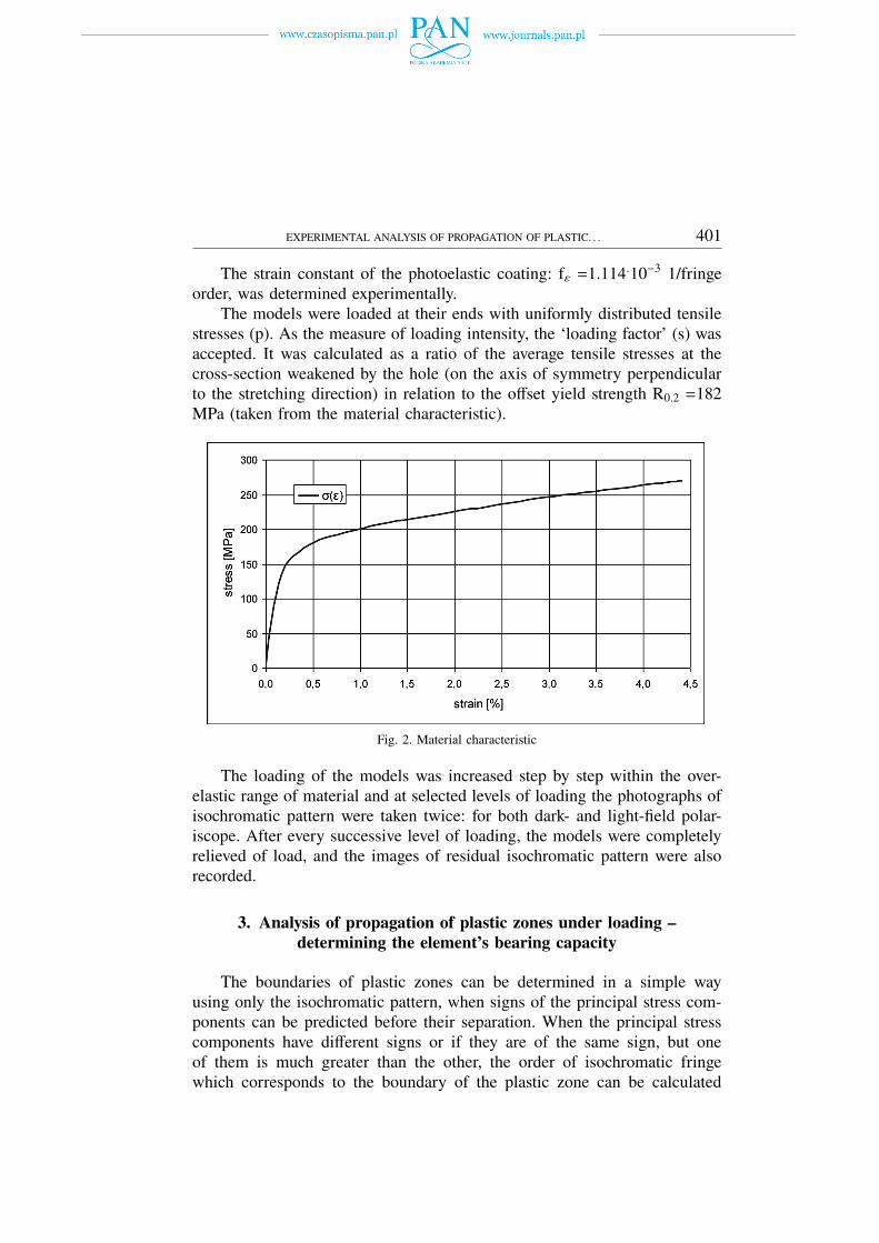
The characteristic of the material (duralumin alloy EN-AW-2024) wasdetermined experimentally on the basis of standard static uniaxial tensiletest (according to PN-EN 10002-1 for the test at ambient temperature). It isshown in Fig. 2.
EXPERIMENTAL ANALYSIS OF PROPAGATION OF PLASTIC. . . 401
The strain constant of the photoelastic coating: fε =1.114.10−3 1/fringeorder, was determined experimentally.
The models were loaded at their ends with uniformly distributed tensilestresses (p). As the measure of loading intensity, the ‘loading factor’ (s) wasaccepted. It was calculated as a ratio of the average tensile stresses at thecross-section weakened by the hole (on the axis of symmetry perpendicularto the stretching direction) in relation to the offset yield strength R0.2 =182MPa (taken from the material characteristic).
Fig. 2. Material characteristic
The loading of the models was increased step by step within the over-elastic range of material and at selected levels of loading the photographs ofisochromatic pattern were taken twice: for both dark- and light-field polar-iscope. After every successive level of loading, the models were completelyrelieved of load, and the images of residual isochromatic pattern were alsorecorded.
3. Analysis of propagation of plastic zones under loading –determining the element’s bearing capacity
The boundaries of plastic zones can be determined in a simple wayusing only the isochromatic pattern, when signs of the principal stress com-ponents can be predicted before their separation. When the principal stresscomponents have different signs or if they are of the same sign, but oneof them is much greater than the other, the order of isochromatic fringewhich corresponds to the boundary of the plastic zone can be calculated
402 BARBARA KOZŁOWSKA
using the Treska-Coulomb yield criterion [21]. Applying the Hooke’s lawand Wertheim’s law, one obtains
mgr =1 + ν
E · fεσpl (1)
where: σpl – yield point of the model’s material;ν – Poisson ratio of the model’s material;E – modulus of elasticity of the model’s material;fε – strain constant of the photoelastic coating.
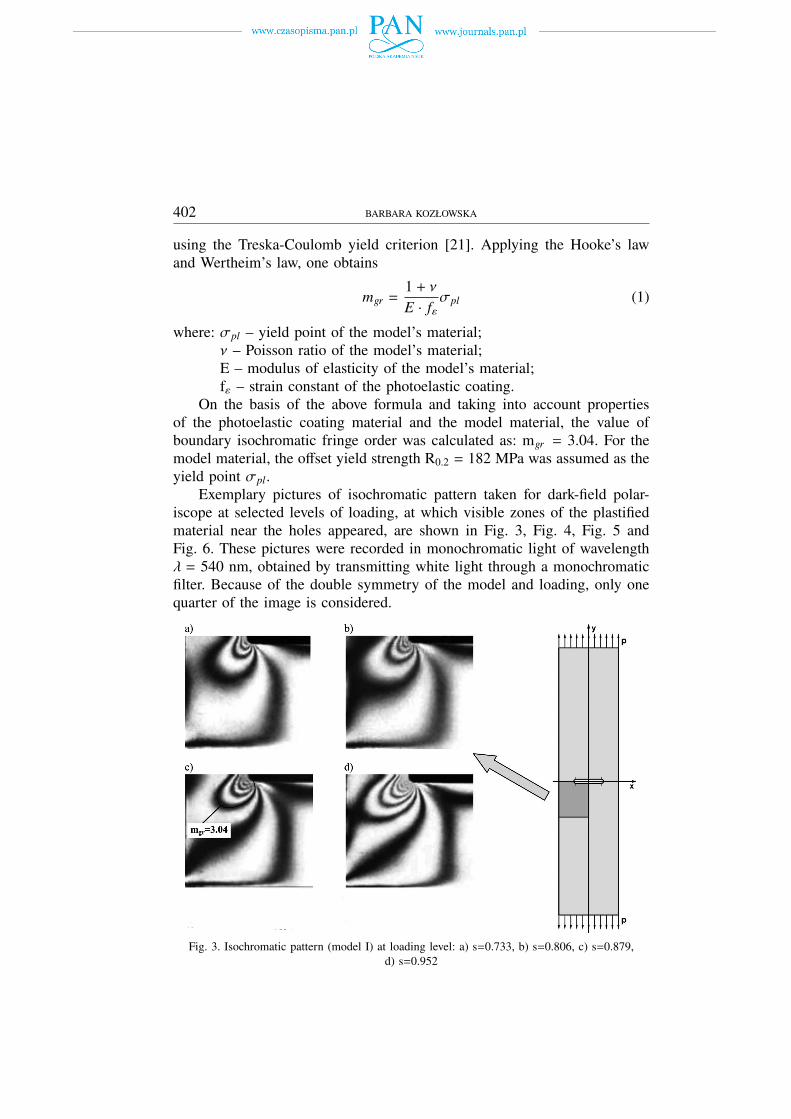
On the basis of the above formula and taking into account propertiesof the photoelastic coating material and the model material, the value ofboundary isochromatic fringe order was calculated as: mgr = 3.04. For themodel material, the offset yield strength R0.2 = 182 MPa was assumed as theyield point σpl.
Exemplary pictures of isochromatic pattern taken for dark-field polar-iscope at selected levels of loading, at which visible zones of the plastifiedmaterial near the holes appeared, are shown in Fig. 3, Fig. 4, Fig. 5 andFig. 6. These pictures were recorded in monochromatic light of wavelengthλ = 540 nm, obtained by transmitting white light through a monochromaticfilter. Because of the double symmetry of the model and loading, only onequarter of the image is considered.
Fig. 3. Isochromatic pattern (model I) at loading level: a) s=0.733, b) s=0.806, c) s=0.879,d) s=0.952
EXPERIMENTAL ANALYSIS OF PROPAGATION OF PLASTIC. . . 403
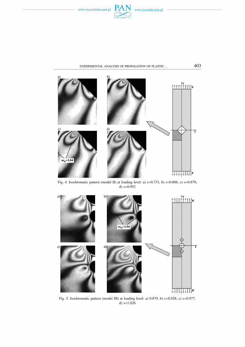
Fig. 4. Isochromatic pattern (model II) at loading level: a) s=0.733, b) s=0.806, c) s=0.879,d) s=0.952
Fig. 5. Isochromatic pattern (model III) at loading level: a) 0.879, b) s=0.928, c) s=0.977,d) s=1.026

404 BARBARA KOZŁOWSKA
Fig. 6. Isochromatic pattern (model IV) at loading level: a) s=0. 595, b) s=0.641, c) s=0.687,d) s=0.733
In Fig. 3c, Fig. 4c, Fig. 5b and Fig. 6c, there are marked exemplarycontours of boundary isochromatic pattern (mgr =3.04) for each model atone of loading levels. The contours of plastic zones determined on the basisof boundary isochromatic pattern for all selected, increasing loading levelsare shown in Fig. 7 and Fig. 8.
Fig. 7. Boundaries of plastic zones for models with one, central hole: a) model I – with slot,b) model II – with square hole
EXPERIMENTAL ANALYSIS OF PROPAGATION OF PLASTIC. . . 405
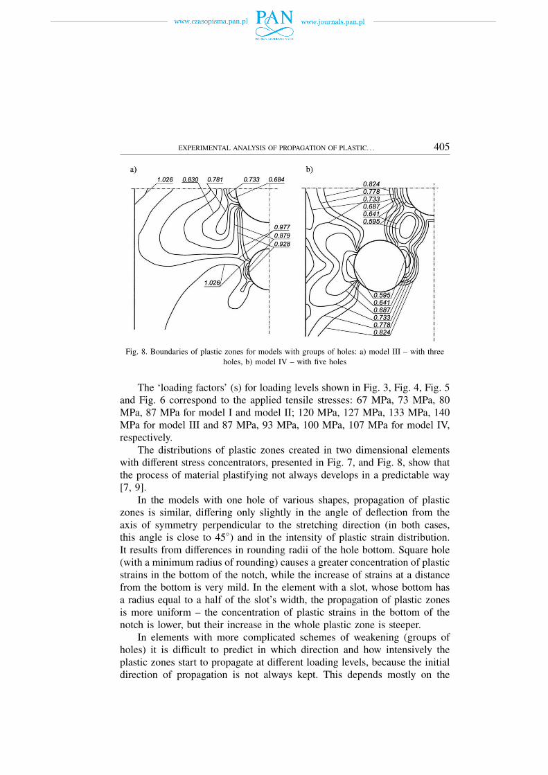
Fig. 8. Boundaries of plastic zones for models with groups of holes: a) model III – with threeholes, b) model IV – with five holes
The ‘loading factors’ (s) for loading levels shown in Fig. 3, Fig. 4, Fig. 5and Fig. 6 correspond to the applied tensile stresses: 67 MPa, 73 MPa, 80MPa, 87 MPa for model I and model II; 120 MPa, 127 MPa, 133 MPa, 140MPa for model III and 87 MPa, 93 MPa, 100 MPa, 107 MPa for model IV,respectively.
The distributions of plastic zones created in two dimensional elementswith different stress concentrators, presented in Fig. 7, and Fig. 8, show thatthe process of material plastifying not always develops in a predictable way[7, 9].
In the models with one hole of various shapes, propagation of plasticzones is similar, differing only slightly in the angle of deflection from theaxis of symmetry perpendicular to the stretching direction (in both cases,this angle is close to 45◦) and in the intensity of plastic strain distribution.It results from differences in rounding radii of the hole bottom. Square hole(with a minimum radius of rounding) causes a greater concentration of plasticstrains in the bottom of the notch, while the increase of strains at a distancefrom the bottom is very mild. In the element with a slot, whose bottom hasa radius equal to a half of the slot’s width, the propagation of plastic zonesis more uniform – the concentration of plastic strains in the bottom of thenotch is lower, but their increase in the whole plastic zone is steeper.
In elements with more complicated schemes of weakening (groups ofholes) it is difficult to predict in which direction and how intensively theplastic zones start to propagate at different loading levels, because the initialdirection of propagation is not always kept. This depends mostly on the
406 BARBARA KOZŁOWSKA
number of holes, their diameter and spacing. For example, in the modelIII, starting from the load level s=0.879, at the moment when plastic zonesaround the smaller holes appear, the direction of development of plasticzones around the central hole apparently changes (Fig. 8a). One can get theimpression that later formed, smaller plastic zones begin to ‘push away’ themain zone, which starts to propagate in the direction inclined at a smallerangle to the x axis of symmetry. In the model IV (with five holes) onecan observe even more variety concerning the number of plastic zones anddirections of their development.
Localization of the areas where first plastic strains are created and direc-tions of their development allow estimating the level of dangerous loading,which can lead to formation of “plastic joints” in the weakest cross-sectionsof the element.
For theoretical estimation of the limits of bearing capacity, we assume therigid-perfectly plastic model of material characteristic. Taking into accountreal material characteristic, the value of loading level accepted as bearingcapacity can be conventionally defined as the force at which the yield point ofthe material is exceeded in the whole element’s cross-section, but maximumstresses (or strains) in this cross-section do not exceed a certain assumedvalue.
4. Analysis of propagation of plastic zones in unloaded (released)elements
Another very important problem in experimental investigation of elastic-plastic states is the analysis of residual strain remaining in unloaded elementafter loading over the yield point.
The photoelastic coating method also provides the largest possibilitiesfor estimating the extensiveness and intensity of the residual (plastic) strain.
Analysis of the development of residual (plastic) strain around the stressconcentrators was carried out for the models I, II, III and IV (Fig. 1). Duringthe test, after each successive level of loading in over-elastic range, the modelswere completely relieved. Then, the images of isochromatic pattern – theresult of permanent material plastifying, were recorded again.
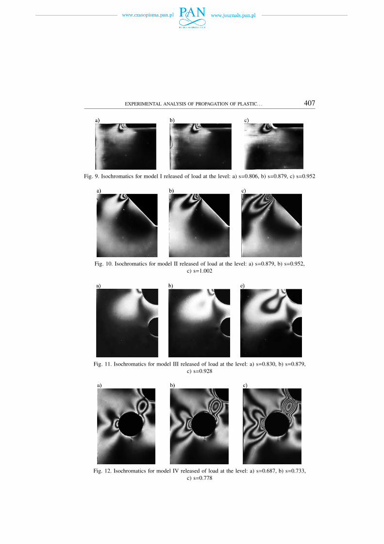
Exemplary pictures of isochromatic patterns in the models I, II, III and IV(in monochromatic light for dark-field polariscope) obtained after relievingof load for selected levels of loading are shown in Fig. 9, Fig. 10, Fig. 11and Fig. 12. Because of the double symmetry of the model and loading, onlyone quarter of the image is considered.
EXPERIMENTAL ANALYSIS OF PROPAGATION OF PLASTIC. . . 407
Fig. 9. Isochromatics for model I released of load at the level: a) s=0.806, b) s=0.879, c) s=0.952
Fig. 10. Isochromatics for model II released of load at the level: a) s=0.879, b) s=0.952,c) s=1.002
Fig. 11. Isochromatics for model III released of load at the level: a) s=0.830, b) s=0.879,c) s=0.928
Fig. 12. Isochromatics for model IV released of load at the level: a) s=0.687, b) s=0.733,c) s=0.778

408 BARBARA KOZŁOWSKA
The boundaries of plastic zones determined on the basis of residualisochromatic pattern for the models I and II (with one hole of differentshapes but the same cross-section) are shown in Fig. 13. Fig. 14 presentsboundaries of plastic zones, obtained in a similar way, in model III and modelIV – with groups of circular holes.
Fig. 13. Boundaries of residual plastic zones for models with one, central hole: a) model I – withslot, b) model II – with square hole
Fig. 14. Boundaries of residual plastic zones for models with groups of holes: a) model III – withthree holes, b) model IV – with five holes
Comparing the obtained results with those found under the same loading(Fig. 7, 8), we can conclude that the areas of residual strain in the unload-ed models are smaller than the plastic zones in the models under loading,although their shape and direction of propagation is similar ([8, 9]). Thefact that the range of plastified material is smaller in the unloaded (released)element can be explained by the reaction of the areas remaining in the elasticstate surrounding plastic zones. It is due to the way of the material releasingfrom the point of characteristic in the over-elastic range which proceedsalong a straight line parallel to this defining elastic state. As a result, the

EXPERIMENTAL ANALYSIS OF PROPAGATION OF PLASTIC. . . 409
residual strain remaining in the material is smaller than the plastic strain inthe corresponding point on the σ-ε curve.
5. Conclusions
Proper assessment of the plastic zones, which form and develop in theconstructional elements working in the over-elastic range of material makesit possible to determine the factor of safety for the whole system. As long asthese zones have a local character, the structure is not endangered by failure.On the other hand, in the result of development of large plastic deformationsthe element becomes a pseudo-mechanism, which cannot work exactly asintended.
The process of development of plastic zones in constructional elementsmay take a variety of forms, depending on the geometry of these elements,the shape of stress concentrators and the way of loading.
The analysis of propagation of plastic zones under increasing loadingmakes it possible to determine the true value of limiting loading and ex-perimental verification of the numerically-calculated bearing capacity of theconstructional elements. It is necessary to mention that bearing capacityis described as extreme loading of the element (in considered cases – theextreme tensile loading).
The analysis of the areas of residual (plastic) strain created in unloaded(released) elements allows us, among other things, to check whether theseelements have the possibility of working after a temporary, emergency over-load exceeding the working value (after which a residual strain may appear).It also allows us determining the directions of propagation of plastic zonesat the cyclic work of the element in over-elastic range.
Comparison of the borders of plastic zones created under loading in theelastic-plastic range with the areas of residual strain in the element releasedof load at the same level gives additional information about the mechanismsof the material plastifying.
Photoelastic coating method allows relatively easy and quick identifica-tion of boundaries of the plastic zones. This gives the possibility of directobservation of the process of forming and developing of plastic strain, itsintensity and direction of propagation.
This method also allows us, through the observation of residual isochro-matic pattern, to analyze the development of residual (plastic) strain zonesthat appear in the unloaded constructional elements in the result of previousloading beyond the yield point.
Thus, the method of photoelastic coating is particularly useful for inves-tigating specific elastic-plastic problems, especially in the cases where the
410 BARBARA KOZŁOWSKA
study of development of plastic zones is necessary for defining the plasticfailure mechanism. It takes place, for example, in the constructional elementswith stress concentrators.
Taking into account also the suitability of the photoelastic coating methodto the full-field quantitative analysis of strain and stress in over-elastic rangeof material [6, 10], we may assume that the method is a good tool foruniversal and complex experimental investigation of processes in which apart of the constructional element is in plastic state.
Manuscript received by Editorial Board, July 16, 2012;final version, October 02, 2012.
REFERENCES
[1] Blum A., Kubiak T., Niezgodziński T.: Analiza wpływu trwałych odkształceń dźwigarówmostowych na rozwój pęknięć lamelarnych. Mat. XXI Sympozjum Mechaniki Eksperymen-talnej Ciała Stałego, Jachranka 2006, 155-160.
[2] Diaz E.V., Armas A.E, Kaufmann G.H., Galizzi G.E.: Fatigue Damage Accumulation arounda Notch Using a Digital Image Measurement System. Experimental Mechanics 44(3), 2004,241-246.
[3] Haldrup K., Nielsen S.F., Wert J.A.: A General Methodology for Full-Field Plastic StrainMeasurements Using X-ray Absorption Tomography and Internal Markers. Experimental Me-chanics 48(2), 2008, 199-211.
[4] Jodłowski H.: Doświadczalne wyznaczanie stref plastycznych w stalach z wyraźną granicąplastyczności. Prace Naukowe Politechniki Warszawskiej – Mechanika z. 217, Oficyna Wyd.PW, Warszawa 2007, 43-48.
[5] Kapkowski J.: Analiza sprężysto-plastyczna jarzma połączenia sworzniowego. Mechanika Teo-retyczna i Stosowana 16(4), 1978, 457-466.
[6] Kapkowski J., Kozłowska B.: Elastic-plastic strain analysis by photoelastic coating method.J. of Theoretical and Applied Mechanics 3(31), 1993, 493-512.
[7] Kozłowska B.: Doświadczalna analiza plastycznego zniszczenia elementów konstrukcji. PraceNaukowe Politechniki Radomskiej – Transport 3(23) 2005, s. 283-288.
[8] Kozłowska B.: Analiza odkształceń trwałych w modelach elementów konstrukcyjnych. 13Polish-Ukrainian Transactions, Theroretical Foundations of Civil Engineering, OficynaWydawnicza PW, Warszawa 2005, 469-472.
[9] Kozłowska B.: The investigation of elastic-plastic states by photoelastic coating method. Proc.of 25th DANUBIA-ADRIA Symposium on Advances in Experimental Mechanics, CeskeBudejovice 2008, 129-130.
[10] Kozłowska B.: Strain and stress analysis in the elastic-plastic state by photoelastic coatingmethod. Proc. of 26th DANUBIA-ADRIA Symposium on Advances in Experimental Mechan-ics, Leoben 2009, 117-118.
[11] Livieri P., Nicoletto G.: Elastoplastic Strain Concentration Factors in Finite Thickness plates.Journal of Strain Analysis 38(1), 2003, 31-36.
[12] Nagy V., Bozóky L., Borbas L.: The mechanical and the geometrical state of railway vehi-cle carriages. Proc. of 25th DANUBIA-ADRIA Symposium on Advances in ExperimentalMechanics, Ceske Budejovice, 2008, 181-182.
[13] Pacey M.N., James M.N., Patterson E.A.: A New Photoelastic Model. for Studying FatigueCrack Closure. Experimental Mechanics 45(1), 2005, 42-52.

EXPERIMENTAL ANALYSIS OF PROPAGATION OF PLASTIC. . . 411
[14] Padmanabhan S., Hubner J.P., Kumar A.V., Ifju P.G.: Load and Boundary Condition Cali-bration Using Full-field Strain Measurement. Experimental Mechanics 46(5), 2006, 569-578.
[15] Pastrama S.D., Iliescu N., Atanasiu C.: Photoelastic analysis for overdeterministic calculationof the stress intensity factor. Proc. of 22nd DANUBIA-ADRIA Symposium on Advances inExperimental Mechanics, Parma 2005, 45-46.
[16] Song S.H., Choi B.H.: Effect of Plastic Zone on the Fatigue Crack Propagation Behaviorbetween Two Fatigue Cracks. Experimental Mechanics 41(3), 2001, 225-231.
[17] Vukić L., Zivković M., Vuković M., Slavković R.: Experimental-numerical method of deter-mination of the most appropriate technology of spot welding. Proc. of 25th DANUBIA-ADRIASymposium on Advances in Experimental Mechanics, Ceske Budejovice 2008, 149-150.
[18] Wung P., Walsh T., Ourchane A., Stewart W., Jie M.: Failure of Spot Welds under in-planeStatic Loading. Experimental Mechanics 41(1), 2001, 100-106.
[19] Zandman F., Redner S., Dally J.W.: Photoelastic coatings. SESA Monograph 3, Westport,1977.
[20] Zhang J.: Two-dimensional in-plane electronic speckle pattern interferometer and its appli-cation to residual stresses determination. Opt. Eng. 37(8), 1998, 2402-2409.
[21] Życzkowski M.: Obciążenia złożone w teorii plastyczności, PWN, Warszawa 1975.
Eksperymentalna analiza propagacji stref plastycznych w zagadnieniach dwuwymiarowych
S t r e s z c z e n i e
W pracy przedstawione zostały wyniki badań przeprowadzonych metodą elastooptycznej warst-wy powierzchniowej na płaskich modelach elementów konstrukcyjnych osłabionych koncentra-torami naprężeń (otworami) o różnych kształtach. Modele, wykonane z duraluminium, zostałyobciążone równomiernie rozłożonymi na końcach naprężeniami rozciągającymi wywołującymiczęściowe uplastycznienie materiału. Na wybranych poziomach obciążenia zostały zarejestrowaneobrazy izochrom, które posłużyły do wyznaczenia granic obszarów uplastycznionych metodąizochromy granicznej (przy wykorzystaniu hipotezy Treski-Coulomba). Po każdym etapie ob-ciążenia, modele były całkowicie odciążane i wtedy ponownie rejestrowano obrazy izochrom(resztkowych), które odzwierciedlają stan odkształceń trwałych pozostałych w materiale po obciąża-niu modelu powyżej granicy plastyczności. W pracy została przeprowadzona dyskusja otrzymanychwyników.