exergoeconomic analysis and genetic algorithm power...
TRANSCRIPT
energyequipsys/ Vol 4/No2/Dec 2016/ 189-203
Energy Equipment and Systems
http://energyequipsys.ut.ac.ir
www.energyeuquipsys.com
Exergoeconomic analysis and genetic algorithm power optimization of an irreversible regenerative Brayton cycle
Authors
Mohammad Mahdi Naserian a
Said Farahat
a*
Faramarz Sarhaddi a
a Department of Mechanical Engineering,
University of Sistan and Baluchestan, Zahedan, Iran
ABSTRACT
In this study, the performance of an irreversible regenerative Brayton cycle is sought through power maximizations using finite-time thermodynamic concept in finite-size components. Optimizations are performed using a genetic algorithm. In order to take into account the finite-time and finite-size concepts in the current problem, a dimensionless mass-flow rate parameter is used to deploy time variations. The results of maximum power state optimizations are investigated considering the impact of dimensionless mass-flow rate parameter variations. One can see that the system performance shows high values of the dimensionless mass-flow rate parameter because of low power production while the high total cost rate is not reasonable. The other objective (besides power maximization) of the current study is to prepare finite-time thermodynamics for studying more practical systems using new thermodynamic modelling, exergy, and cost analyses of the current system.
Article history:
Received : 9 April 2016 Accepted : 16 August 2016
Keywords: Finite-Time Thermodynamic, Exergoeconomic, Regenerative Brayton Cycle, Optimization,
Maximum Power.
1. Introduction
Thermodynamic processes take place in finite-size components during finite time; therefore, the Carnot heat efficiency is not of great importance as thermodynamic equilibrium is unreachable and irreversibility appears. Literature is rife with attempts made to improve analysis techniques in order to account for both internal and external irreversibility in heat engines. External irreversibility is due to the temperature difference between fluid flows of the heat exchangers. The internal irreversibility is *Corresponding author: Said Farahat Address: Department of Mechanical Engineering, University of Sistan and Baluchestan, Zahedan, Iran E-mail address: [email protected]
present inside the system’s boundaries and can be carried out by the working fluid.
Curzon and Ahlborn [1] investigated the effect of external irreversibility on the Carnot cycle’s output power and thermal efficiency. Thermal efficiency was expressed as in Eq. (1) at the maximum output power ( and are temperatures at cold and hot heat exchangers, respectively). Systems with internal reversibility are known as endoreversible cycles. Bejan [2] applied the endoreversible concept to the Brayton cycle and concluded that the efficiency of the cycle is independent of thermal conductance distribution. However, the effect of internal irreversibility cannot be neglected with regard to the thermodynamic performance of a heat engine. In a separate
190 Mohammad Mahdi Naserian et al./energyequipsys / Vol 4/No2/Dec 2016
study, comparison was established between an endoreversible Carnot cycle, and the same system with both internal and external irreversibility as developed by Wu [3]. It was shown that internal irreversibility reduces power and efficiency. Gordon [4] analysed heat engines considering finite-rate heat transfer and finite-capacity thermal reservoirs.
√
(1)
Heat engines operate in finite time; therefore, realistic study of their optimal performance (the highest efficiency at the maximum power) is feasible through the concept of finite-time thermodynamics [5]. This method was applied to the optimization of a regenerative endoreversible Brayton cycle for finite thermal capacitance rates of the heat reservoirs as seen in the work of Cheng and Chen [6]. In the undertaken research, application of regenerators led to a decrease in the maximum power and thermal efficiency. Further analyses were performed on regenerative and irreversible models of Brayton heat engines [Cheng and Chen, 7; Chen et al., 8]. In the model introduced in this paper, all irreversibility sources associated with the finite-time heat transfer process were taken into account.
Optimization of real systems is confined to thermal performance and physical constraints. Bejan [9] established two optimization approaches based on these two elements: (i) improving thermal performance subject to physical size constraints (e.g. the minimum entropy generation) and (ii) physical size minimization subject to specified thermodynamic performance. He concluded that both approaches lead to the same physical configuration. Herrera et al. [10] used heat exchanger size and admissible pressure drop as design constraints for an irreversible regenerative Brayton cycle. In the model, finite-time thermodynamics and optimization were used to determine the maximum power and minimum entropy generation, along with the global maximum net power. The performance of an air-standard rectangular cycle with heat transfer loss and variable specific heats of working fluid was analysed using finite-time thermodynamics, as seen in the work of Wang et al. [11]. They found that the effects of heat transfer loss and variable specific heats of working fluid on the cycle performance were obvious. Agnew et al. [12]
presented a finite-time analysis of a tri-generation cycle that was based on coupled power and refrigeration Carnot cycles.
In various studies, the thermal parameters used as criteria for thermodynamic optimization of heat engines are different. Power density and exergy density are two objective functions used in an irreversible Brayton cycle with regeneration/cogeneration [13 and 14]. Dimensionless power density and thermal efficiency were optimized for Braysson cycles using the Non-dominated Sorting Genetic Algorithm and finite time thermodynamic analysis (Sadatsakkak et al. [15]). Açıkkalp [16] investigated the irreversible refrigeration cycle by using the exergetic sustainability index. In that study, it was recommended that the exergetic sustainability index is an important parameter for the environmental effects of any system. In addition, many recent papers concentrate on evaluation of different thermal cycles using finite-time thermodynamics and exergy analysis [17–27]. Angulo-Brown et al. [28] proposed an ecological criterion as Eq. (2) for finite-time Carnot heat engines, where TL is the temperature of the cold heat reservoir, is the power output, and is the entropy-generation rate. Yan [29] discussed the results of Angulo’s study and suggested that the definition of an ecological function like Eq. (3) is more reasonable.
(2)
(3)
where T0 is the dead-state temperature. Huang et al. [30] and Chen et al. [31] carried out an ecological exergy optimization for heat engines. They concluded that even though the work output was reduced, the ecological exergy study results in a better performance than that obtained with the maximum power output conditions. The effect of the regenerator’s effectiveness on optimal performance for the maximum ecological function conditions was discussed by Ust et al. [32] and Kumara et al. [33]. Ecological performance analysis of an endoreversible modified Brayton cycle was conducted by Long and Liu [34] and Wang et al. [35]. Ecological optimization of an irreversible Brayton cycle with regeneration, inter-cooling, and reheating was performed by del Rio Oliveira et al. [36]. Naserian et al. [37] sought the optimal performance of a regenerative
Mohammad Mahdi Naserian et al./energyequipsys / Vol 4/No2/Dec 2016 191
Brayton cycle through power and then multi-objective ecological function maximization using a finite-time thermodynamic concept and finite-size components. A dimensionless parameter that embeds the time variable was defined by them.
Durmusoglu et al. [38] optimized an irreversible regenerative closed Brayton cycle using a thermoeconomic objective criterion, which was defined as the ratio of net power output to the total cost rate. Sadatsakkak et al. [39] performed a multi-objective optimization on an irreversible regenerative closed Brayton cycle using three objective functions that included the power output, the ecological coefficient of performance, and the thermoeconomic criterion.
Thermo-economic analysis of irreversible refrigeration and heat pump systems was demonstrated for specified cooling and heating loads by Qureshi and Zubair [40]. As a conclusion, they found that endoreversible models provide a reasonable basis for initially understanding real systems. Ahmadi et al. [41] carried out a thermo-economic optimization of irreversible Stirling heat pump cycles that includes both internal and external irreversibilities together with finite-heat capacities of external reservoirs.
Thermo-economic optimization of irreversible power systems with finite thermal capacitances for design situation was performed by Qureshi [42]. The investigation was performed with respect to the case of specified power output. Sahraie et al. [43] studied a thermodynamic modelling and thermo-economic optimization of an irreversible absorption heat pump.
In the current study, an irreversible closed-cycle Brayton engine with regeneration is investigated. The unique aspects of the current research are as follows: A dimensionless parameter that includes
finite-time and size concepts is used in exergoeconomic analysis and optimization of the system.
An ecological function concept is linked to the exergoeconomic analysis by adding the exergy destruction cost rate to the total cost rate equation.
Mass flow rate of fuel is added to the decision-making parameters and it can vary independently of working flow mass flow rate.
Nomenclature
T Temperature (K)
W Power (kW)
S Entropy rate (kW/K)
C Cost rate ($/s)
eE Ecological function (kW)
Pc Specific heat (kJ/kg.K)
P Pressure (bar)
E Exergy rate (kW)
m Mass flow rate (kg/s)
Q Heat transfer rate (kW)
A Area (m2)
U Overall heat transfer rate
(kW/m2K)
F Dimensionless mass flow rate
R Specific gas constant (J/kg.K)
PR Pressure ratio
Z Cost rate associated with capital
investment and the maintenance
cost
r Thermal conductance ratio
C Cost ($)
c Capacity ratio, specific cost
N Number of hours
Z Purchase cost ($)
AF Air fuel ratio
LH
V
Lower heating value
e Specific exergy (kJ/kg)
Greek symbols
efficiency Effectiveness
Maintenance factor
Subscripts
L Low, loss
H High
CA Curzon and Ahlborn
g Generation, hot line flow
0 Dead state
me Maximum ecological
mp Maximum power
C Carnot
W Working fluid
T Total
192 Mohammad Mahdi Naserian et al./energyequipsys / Vol 4/No2/Dec 2016
D Destruction
f Fuel (components)
F Fuel (CH4)
P Product
gt Gas turbine
CC Combustion chamber
AC Air compressor
R &
HR
Heat regenerator
HTHE High-temperature heat
exchanger
LTHE Low-temperature heat
exchanger
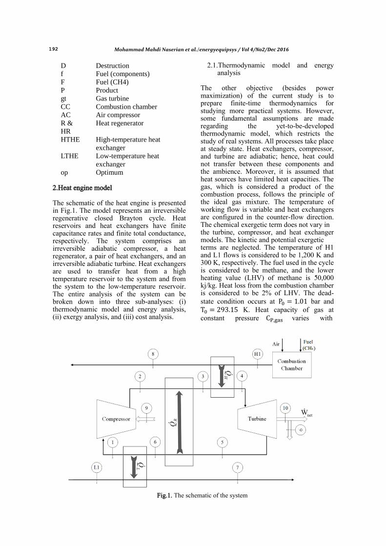
op Optimum 2.Heat engine model The schematic of the heat engine is presented in Fig.1. The model represents an irreversible regenerative closed Brayton cycle. Heat reservoirs and heat exchangers have finite capacitance rates and finite total conductance, respectively. The system comprises an irreversible adiabatic compressor, a heat regenerator, a pair of heat exchangers, and an irreversible adiabatic turbine. Heat exchangers are used to transfer heat from a high temperature reservoir to the system and from the system to the low-temperature reservoir. The entire analysis of the system can be broken down into three sub-analyses: (i) thermodynamic model and energy analysis, (ii) exergy analysis, and (iii) cost analysis.
2.1.Thermodynamic model and energy analysis
The other objective (besides power maximization) of the current study is to prepare finite-time thermodynamics for studying more practical systems. However, some fundamental assumptions are made regarding the yet-to-be-developed thermodynamic model, which restricts the study of real systems. All processes take place at steady state. Heat exchangers, compressor, and turbine are adiabatic; hence, heat could not transfer between these components and the ambience. Moreover, it is assumed that heat sources have limited heat capacities. The gas, which is considered a product of the combustion process, follows the principle of the ideal gas mixture. The temperature of working flow is variable and heat exchangers are configured in the counter-flow direction. The chemical exergetic term does not vary in the turbine, compressor, and heat exchanger models. The kinetic and potential exergetic terms are neglected. The temperature of H1 and L1 flows is considered to be 1,200 K and 300 K, respectively. The fuel used in the cycle is considered to be methane, and the lower heating value (LHV) of methane is 50,000 kj/kg. Heat loss from the combustion chamber is considered to be 2% of LHV. The dead-state condition occurs at bar and K. Heat capacity of gas at constant pressure varies with
Fig.1. The schematic of the system

Mohammad Mahdi Naserian et al./energyequipsys / Vol 4/No2/Dec 2016 193
temperature, as indicated in Eq. (4) (Naserian et al. [37]).
( )
(4)
Energy analysis is performed on each component of the cycle separately. Energy balance equations are derived for the compressor (Eq. 5), turbine (Eq. 6), high-temperature heat exchanger (Eq. 7), and low-temperature heat exchanger (Eq. 8) as follows.
(
[( )
])
(5)
( [ ( )
])
(6)
The efficiency of the compressor ( ) is assumed to be 0.9 and the efficiency of the turbine ( ) is assumed to be 0.95.
( )
( )
( )
(7)
( )
( )
( )
(8)
where and are the effectiveness of high-temperature and low-temperature heat sources, respectively. The embedded parameters in the above relations are described in Eqs. (9–14).
( ) { }
(9)
{ }
(10)
(
)
(11)
(
)
(12)
(
)
(13)
(
)
(14)
Energy analysis of the heat regenerator is detailed in Eqs. (15–18).
( )
( )
(15)
(16)
(
)
(17)
(
)
(18)
Energy analysis of combustion chamber
(19)
(20)
( ) (21)
In order to calculate the air-fuel ratio, the following equation is derived from Eqs. 19–21.
(22)
In this analysis, taking into account the assumption of constant temperature of the combustion chamber outlet (1,200 K), and the constant temperature of air at the inlet of the combustion chamber (equals to 293 K), the air-fuel ratio is constant and calculated as follows.
(23)
In order to enter the finite-size constraint to the problem, the total thermal conductance of system heat exchangers ( ) ) is considered constant [2, 10, and 37]. Moreover, assuming that the mass flow rate is finite and non-zero, time will be constrained, too. For taking into account the time and the size constraints in the current problem, using the dimensionless mass-flow parameter (F) is the perfect choice. The parameter was defined by Naserian et al. [37]. However, the definition is modified for the current problem (where the mass flow rate
194 Mohammad Mahdi Naserian et al./energyequipsys / Vol 4/No2/Dec 2016
of fuel can vary independently of the working flow mass flow rate) as in Eq. (24).
[( )
]
(24)
where and ( ) are the least heat capacity of the gas in the system and total thermal conductance of heat exchangers, respectively.
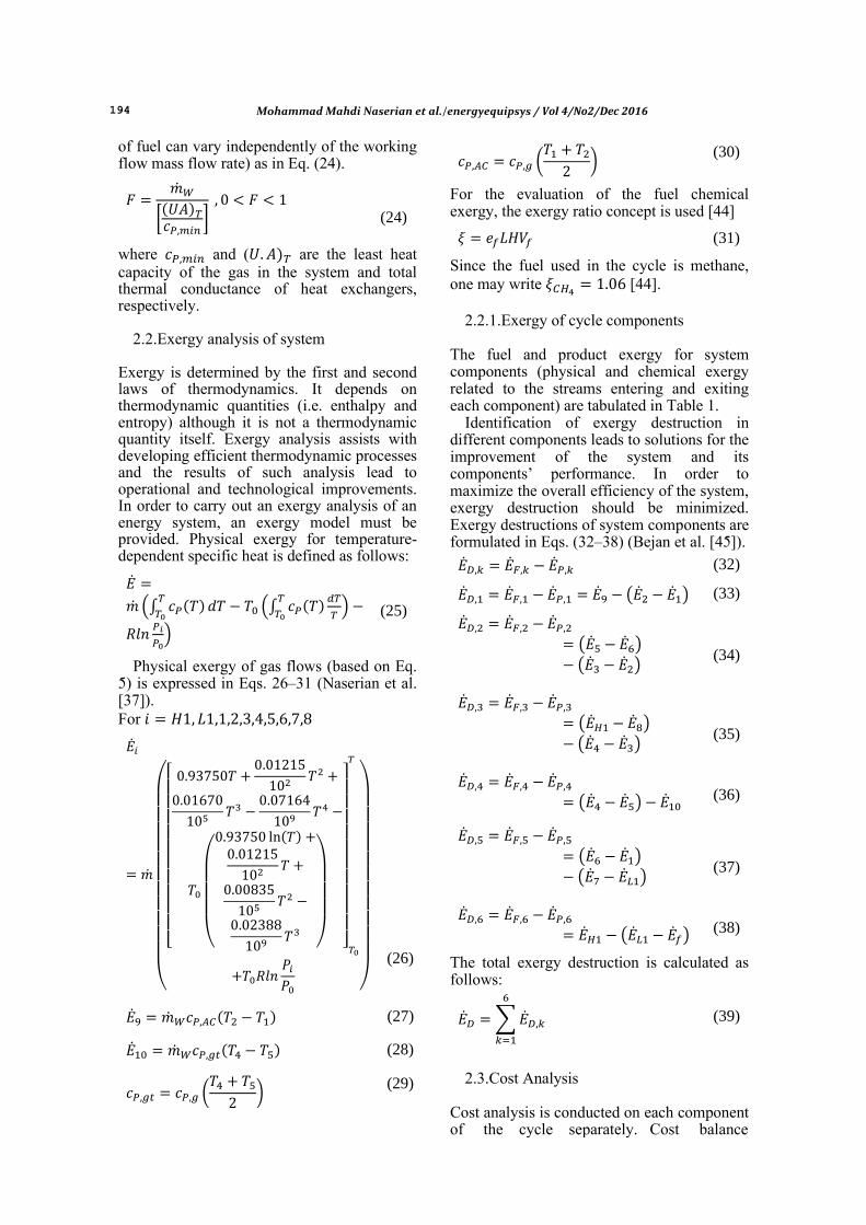
2.2.Exergy analysis of system Exergy is determined by the first and second laws of thermodynamics. It depends on thermodynamic quantities (i.e. enthalpy and entropy) although it is not a thermodynamic quantity itself. Exergy analysis assists with developing efficient thermodynamic processes and the results of such analysis lead to operational and technological improvements. In order to carry out an exergy analysis of an energy system, an exergy model must be provided. Physical exergy for temperature-dependent specific heat is defined as follows:
(∫ ( )
(∫ ( )
)
)
(25)
Physical exergy of gas flows (based on Eq. 5) is expressed in Eqs. 26–31 (Naserian et al. [37]). For
(
[
(
( )
)
]
)
(26)
( ) (27)
( ) (28)
(
) (29)
(
) (30)
For the evaluation of the fuel chemical exergy, the exergy ratio concept is used [44]
(31)
Since the fuel used in the cycle is methane, one may write [44].
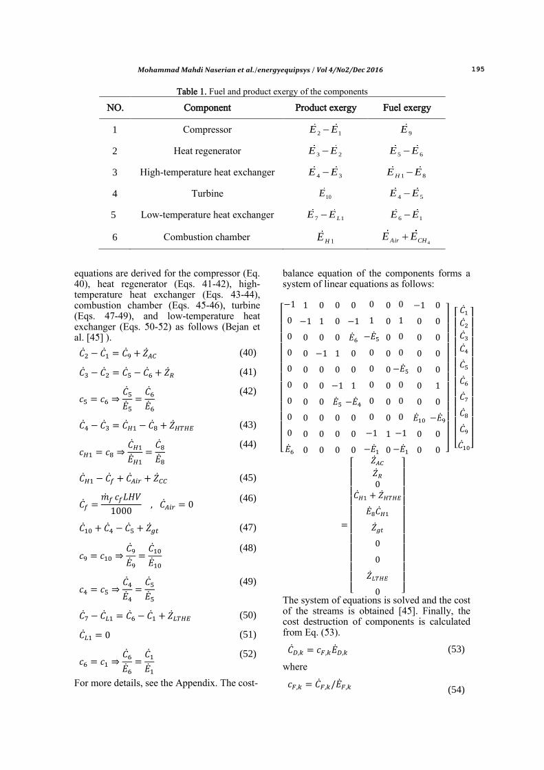
2.2.1.Exergy of cycle components The fuel and product exergy for system components (physical and chemical exergy related to the streams entering and exiting each component) are tabulated in Table 1.
Identification of exergy destruction in different components leads to solutions for the improvement of the system and its components’ performance. In order to maximize the overall efficiency of the system, exergy destruction should be minimized. Exergy destructions of system components are formulated in Eqs. (32–38) (Bejan et al. [45]).
(32)
( ) (33)
( )
( )
(34)
( )
( )
(35)
( )
(36)
( )
( )
(37)
( )
(38)
The total exergy destruction is calculated as follows:
∑
(39)
2.3.Cost Analysis
Cost analysis is conducted on each component of the cycle separately. Cost balance
Mohammad Mahdi Naserian et al./energyequipsys / Vol 4/No2/Dec 2016 195
Table 1. Fuel and product exergy of the components
NO. Component Product exergy Fuel exergy
1 Compressor 2 1E E 9E
2 Heat regenerator 3 2E E 5 6E E
3 High-temperature heat exchanger 4 3E E 1 8HE E
4 Turbine 10E 4 5E E
5 Low-temperature heat exchanger 7 1LE E 6 1E E
6 Combustion chamber 1HE 4Air CHE E
equations are derived for the compressor (Eq. 40), heat regenerator (Eqs. 41-42), high-temperature heat exchanger (Eqs. 43-44), combustion chamber (Eqs. 45-46), turbine (Eqs. 47-49), and low-temperature heat exchanger (Eqs. 50-52) as follows (Bejan et al. [45] ).
(40)
(41)
(42)
(43)
(44)
(45)
(46)
(47)
(48)
(49)
(50)
(51)
(52)
For more details, see the Appendix. The cost-
balance equation of the components forms a system of linear equations as follows:
[
]
[
]
[
]
The system of equations is solved and the cost of the streams is obtained [45]. Finally, the cost destruction of components is calculated from Eq. (53).
(53)
where
(54)
196 Mohammad Mahdi Naserian et al./energyequipsys / Vol 4/No2/Dec 2016
The total cost rate of the product for the current problem is now defined as Eq. (55).
∑
∑
(55)
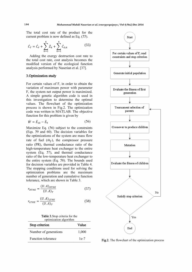
Adding the exergy destruction cost rate to the total cost rate, cost analysis becomes the modified version of the ecological function analysis performed by Naserian et al. [37]. 3.Optimization study For certain values of F, in order to obtain the variation of maximum power with parameter F, the system net output power is maximized. A simple genetic algorithm code is used in this investigation to determine the optimal values. The flowchart of the optimization process is shown in Fig.2. The optimization code was written in MATLAB. The objective function for this problem is given by
(56)
Maximize Eq. (56) subject to the constraints (Eqs. 59 and 60). The decision variables for the optimizations of the system are mass flow rate of fuel ( ), the compressor pressure ratio (PR), thermal conductance ratio of the high-temperature heat exchanger to the entire system (Eq. 57), and thermal conductance ratio of the low-temperature heat exchanger to the entire system (Eq. 58). The bounds used for decision variables are provided in Table 4. The stopping conditions used for solving the optimization problems are the maximum number of generation and cumulative function tolerance, which are shown in Table 3.
( ) ( )
(57)
( ) ( )
(58)
Table 3.Stop criteria for the optimization algorithm
Stop criterion Value
Number of generations 1,000
Function tolerance 1e-7
Fig.2. The flowchart of the optimization process
Mohammad Mahdi Naserian et al./energyequipsys / Vol 4/No2/Dec 2016 197
3.2.Constraints Actual systems have physical constraints that must be considered for optimization. The significant constraint taken into account in this study is the size of the heat exchangers. The total thermal conductance of heat exchangers is constant (Bejan, 2; Herrera at al., 10; Chen et al., 31). This assumption results in the following relations (Eqs. 59 and 60), where is described as Eq. 61. The bounds used for decision variables are listed in Table 4.
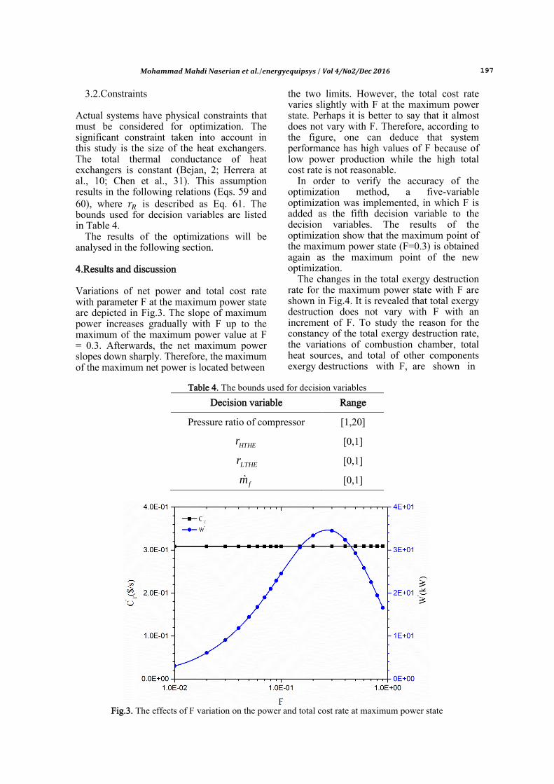
The results of the optimizations will be analysed in the following section. 4.Results and discussion Variations of net power and total cost rate with parameter F at the maximum power state are depicted in Fig.3. The slope of maximum power increases gradually with F up to the maximum of the maximum power value at F = 0.3. Afterwards, the net maximum power slopes down sharply. Therefore, the maximum of the maximum net power is located between
the two limits. However, the total cost rate varies slightly with F at the maximum power state. Perhaps it is better to say that it almost does not vary with F. Therefore, according to the figure, one can deduce that system performance has high values of F because of low power production while the high total cost rate is not reasonable.
In order to verify the accuracy of the optimization method, a five-variable optimization was implemented, in which F is added as the fifth decision variable to the decision variables. The results of the optimization show that the maximum point of the maximum power state (F=0.3) is obtained again as the maximum point of the new optimization.
The changes in the total exergy destruction rate for the maximum power state with F are shown in Fig.4. It is revealed that total exergy destruction does not vary with F with an increment of F. To study the reason for the constancy of the total exergy destruction rate, the variations of combustion chamber, total heat sources, and total of other components exergy destructions with F, are shown in
Table 4. The bounds used for decision variables
Decision variable Range
Pressure ratio of compressor [1,20]
HTHEr
[0,1]
LTHEr
[0,1]
fm
[0,1]
Fig.3. The effects of F variation on the power and total cost rate at maximum power state

198 Mohammad Mahdi Naserian et al./energyequipsys / Vol 4/No2/Dec 2016
Fig.5. Comparison of the diagrams proves that a great part of the total exergy destruction rate is derived from exergy destruction of the combustion chamber. Moreover, the pattern of the total exergy destruction rate curve is almost the same as (and originated from) that for the combustion chamber.
The effect of F on fuel exergy (exergy inserted to the high-temperature heat exchanger), total exergy destruction in thermal sources, and subtraction of total exergy destruction in thermal sources from fuel exergy is tracked in Fig.6. Fuel exergy
and the total exergy destruction in thermal sources constantly increase with F. For F smaller than 0.1, the subtraction curve and fuel exergy approximately take the same values and the difference between them increases afterwards due to the rapid growth of heat-transfer exergy destruction. At higher values of F, fuel exergy does not return an appropriate measure about attainable exergy (or net output power) due to neglecting the exergy destruction of thermal sources (external irreversibility). The subtraction curve takes this deficiency into account. This
Fig.4.Variation of total exergy destruction with F in the maximum power state
Fig.5. Variation of exergy destruction rate of the system components in the maximum power state

Mohammad Mahdi Naserian et al./energyequipsys / Vol 4/No2/Dec 2016 199
model and fuel exergy follow the same pattern up to F = 0.1. The subtraction curve decelerates thereafter and decreases after its maximum value at F = 0.4. By comparing this figure with Fig. 3, it is clear that the trend of subtraction curve variation with F is almost similar to net output power.
The variation in the fuel mass flow rate with F is depicted in Fig.7. For certain values of F, the system utilized its maximum value of
fuel mass flow rate (here 1 kg/s) to produce the maximum power. According to Figs. 3 and 5, and the equation discussed in the Exergy Analysis and Cost Analysis sections, the exergy destruction rate of the combustion chamber and its destruction cost rate are proportional to the fuel mass flow rate. Therefore, the behaviour of the total cost rate and total exergy destruction rate curves are justified.
Fig.6. The effect of F on fuel exergy, total exergy destruction in thermal sources, and
the difference between them
Fig.7. Variation of fuel mass flow rate with
200 Mohammad Mahdi Naserian et al./energyequipsys / Vol 4/No2/Dec 2016
5.Conclusion The performance of an irreversible regenerative Brayton cycle was sought through power maximization using a finite-time thermodynamic concept in finite-size components. The decision-making parameters were mass flow rate of fuel, the compressor-pressure ratio, thermal conductance ratio of the high-temperature heat exchanger to the entire system, and thermal conductance ratio of the low-temperature heat exchanger to the entire system. Optimizations were performed using a genetic algorithm. The other objective (besides power maximization) of the current study is to prepare finite-time thermodynamics for studying more practical systems. For this reason, thermodynamic modelling, and exergy and cost analyses of the current system were conducted in detail. The results of maximum power were analysed considering the impact of F variations. System performance at high values of F because of low power production given a high total cost rate was not reasonable. A great part of total exergy destruction was derived from exergy destruction of the combustion chamber. Moreover, the constant pattern of the total exergy destruction rate curve was almost the same as (and originating from) that from the combustion chamber. However, the total exergy destruction in thermal sources and other components constantly increases with F. Fuel exergy investigation showed that, unlike fuel exergy, the subtraction of total exergy destruction in thermal sources from fuel exergy variation with F was almost similar to net output power. References [1] Curzon FL, Ahlborn B., Efficiency of a
Carnot Engine at Maximum Power Output, American Journal of Physics (1975) 43(1): 22–4.
[2] Bejan A., Theory of Heat-Transfer Irreversible Power-Plants. International Journal of Heat and Mass Transfer (1988)31(6):1211–9.
[3] Wu C., Power Optimization of a Finite Time Carnot Heat Engine, Energy (1988)13(9): 681–7.
[4] Gordon JM., Observations on Efficiency of Heat Engines Operating at Maximum Power, American Journal of Physics (1990)58(4): 370–5.
[5] Wu C, Kiang RL., Finite-Time Thermodynamic Analysis of a Carnot
Engine with Internal Irreversibility, Energy (1992) 1(12): 1173–8.
[6] Cheng CY, Chen CK., Power Optimization of an Endoreversible Regenerative Brayton Cycle, Energy (1996)2(4): 241–7.
[7] Cheng CY, Chen CK, Power Optimization of an Irreversible Brayton Heat Engine, Energy Sources (1997)1(5): 461–74.
[8] Chen LG, Sun FR, Wu C, Kiang RL., Theoretical Analysis of the Performance of a Regenerative Closed Brayton Cycle with Internal Irreversibilities, Energy Conversion and Management (1997)3(9): 871–7.
[9] Bejan A., Thermodynamic Optimization Alternatives, Minimization of Physical Size Subject to Fixed Power, International Journal Energy Research (1999)23: 1111–21.
[10] Carlos A Herrera, Jairo A Sandoval and Miguel E Rosillo, Power and Entropy Generation of an Extended Irreversible Brayton Cycle, Optimal Parameters and Performance, Journal of Physics D: Applied Physics (2006)39: 3414–3424.
[11] Wang, C., Chen, L., Ge, Y., Sun, F., Performance Analysis of an Endoreversible Rectangular Cycle with Heat Transfer Loss and Variable Specific Heats of Working Fluid, Journal homepage: www. IJEE. IEE Foundation, (2015) 6(1): 73-80.
[12] Agnew B., Walker S., Ng B., Tam I. C., Finite Time Analysis of a Tri-Generation Cycle, Energies (2015) 8(6): 6215-6229.
[13] Chen LG, Zheng JL, Sun FR, Wu C., Power Density Analysis and Optimization of a Regenerated Closed Variable-Temperature Heat Reservoir Brayton Cycle, Journal of Physics D: Applied Physics (2001) 3(11):1727–39.
[14] Ust Y, Sahin B, Yilmaz T., Optimization of a Regenerative Gas-Turbine Cogeneration System Based on a New Exergetic Performance Criterion, Exergetic Performance Coefficient, Proceedings of the Institution of Mechanical Engineers Part A(2007)221:447–58.
[15] Sadatsakkak S. A., Ahmadi M. H., Bayat R., Pourkiaei S. M., Feidt M., Optimization Density Power and Thermal Efficiency of an Endoreversible Braysson Cycle by Using Non-Dominated Sorting Genetic Algorithm, Energy Conversion and Management (2015) 93: 31-39.
Mohammad Mahdi Naserian et al./energyequipsys / Vol 4/No2/Dec 2016 201
[16] Acıkkalp E., Exergetic Sustainability Evaluation of Irreversible Carnot Refrigerator, Physica A, Statistical Mechanics and its Applications (2015) 436: 311–320.
[17] Açıkkalp E., Yamık H., Limits and Optimization of Power Input or Output of Actual Thermal Cycles, Entropy (2013) 15: 3219–3248.
[18] Ebrahimi R., Effects of Variable Specific Heat Ratio on Performance of an Endoreversible Otto Cycle, Relation (2010)24: 31.
[19] Madadi V., Tavakoli V., Rahimi A., First and Second Thermodynamic Law Analyses Applied to a Solar Dish Collector, Journal of Non-Equilibrium Thermodynamics (2014) 39: 183–197.
[20] Vaudrey A., Lanzetta F., Feidt M., H. B. Reitlinger and the Origins of the Efficiency at Maximum Power Formula for Heat Engines, Journal of Non-Equilibrium Thermodynamics (2014)39: 199–203.
[21] Açıkkalp E, Yamık H., Modeling and Optimization of Maximum Available Work for Irreversible Gas Power Cycles with Temperature Dependent Specific Heat, Journal of Non-Equilibrium Thermodynamics (2015) 40(1):25-39.
[22] Yang B, Chen L G, Ge Y L, Sun F R., Exergy Performance Analyses of an Irreversible Two-Stage Intercooled Regenerative Reheated Closed Brayton CHP Plant, International Journal of Exergy (2014)14(4): 459-483.
[23] Yang B, Chen L G, Ge Y L, Sun F R., Finite time exergoeconomic performance of a real, intercooled, regenerated gas turbine cogeneration plant. Part 2: heat conductance distribution and pressure ratio optimization. International Journal of Low-Carbon Technologies (2014) 9(4): 262-267.
[24] Zhang Z. L., Chen L. G., Sun F. R., Performance Optimization for Two Classes of Combined Regenerative Brayton and Inverse Brayton Cycles, International Journal of Sustainable Energy (2014) 33(4): 723-741.
[25] Zhang Z. L., Chen L. G., Ge Y. L., Sun F. R., Thermodynamic Analysis for a Regenerative Gas Turbine Cycle in Cooling Process, International Journal of Energy and Environment (2014) 5(6): 701-708.
[26] Yang B., Chen L. G., Ge Y. L., Sun F.
R., Exergy Analyses of an Endoreversible Closed Regenerative Brayton Cycle CCHP Plant, International Journal of Energy and Environment (2014) 5(6): 655-668.
[27] Acıkkalp E., Methods Used for Evaluation of Actual Power Generating Thermal Cycles and Comparing Them, International Journal Electrical Power & Energy Systems (2015) 69: 85–89.
[28] Angulo-Brown F., An Ecological Optimization Criterion for Finite-Time Heat Engines, Journal of Applied Physics (1991) 6(11):7465–9.
[29] Yan Z., Comment on an Ecological Optimization Criterion for Finite-Time Heat Engines, Journal of Applied Physics (1993) 73(7):3583.
[30] Cheng C.Y., Chen C.K., Ecological Optimization of an Endoreversible Brayton Cycle, Energy Conversion and Management (1998) 3(1-2):33–44.
[31] Chen C.Y., Chen C.K., Ecological Optimization of an Irreversible Brayton Heat Engine, Journal Physics D: Applied Physics (1999) 32:350–7.
[32] Ust, Y., Safa, A., Sahin, B. Ecological Performance Analysis of an Endoreversible Regenerative Brayton Heat-Engine, Applied Energy (2005) 80(3): 247-260.
[33] Kumara R., Kaushikb S. C., Kumarc R. Performance Analysis of an Irreversible Regenerative Brayton Cycle Based on Ecological Optimization Criterion, International Journal of Thermal & Environmental Engineering, (2015) 9(1): 25-32.
[34] Long R., Liu W., Ecological Optimization for General Heat Engines, Physica A: Statistical Mechanics and its Applications (2015) 434: 232-239.
[35] Wang J., Chen L., Ge Y., Sun F., Ecological Performance Analysis of an Endoreversible Modified Brayton Cycle, International Journal Sustainable Energy (2014) 33(3): 619-634.
[36] Rio Oliveira S., Scalon V. L., Repinaldo V. P., Ecological Optimization of an Irreversible Brayton Cycle with Regeneration, Inter-Cooling and Reheating, Applied Mathematical Model (2015).
[37] Naserian M. M., Farahat S., Sarhaddi F. Finite Time Exergy Analysis and Multi-Objective Ecological Optimization of a
202 Mohammad Mahdi Naserian et al./energyequipsys / Vol 4/No2/Dec 2016
Regenerative Brayton Cycle Considering the Impact of Flow Rate Variations, Energy Conversion and Management (2015) 103: 790-800.
[38] Durmusoglu Y., Ust Y., Thermodynamic Optimization of an Irreversible Regenerative Closed Brayton Cycle Based on Thermoeconomic Performance Criterion, Applied Mathematical Model (2014) 38: 5174–5186.
[39] Sadatsakkak S. A., Ahmadi M. H., Ahmadi M. A., Thermodynamic and Thermo-Economic Analysis and Optimization of an Irreversible Regenerative Closed Brayton Cycle, Energy Conversion and Management (2015) 94: 124-129. [40] Qureshi B. A., Zubair S. M., Thermoeconomic Considerations in the Allocation of Heat Transfer Inventory for Irreversible Refrigeration and Heat Pump Systems, International Journal of Refrigeration (2015) 54: 67-75.
[41] Ahmadi M. H., Ahmadi M. A., Bayat R., Ashouri M., Feidt M. Thermo-Economic Optimization of Stirling Heat Pump by Using Non-Dominated Sorting Genetic Algorithm, Energy Conversion and Management (2015) 91: 315-322.
[42] Qureshi B. A., Thermoeconomic Considerations in the Allocation of Heat Transfer Inventory for Irreversible Power Systems, Applied Thermal Engineering (2015) 90: 305-311.
[43] Sahraie H., Mirani M. R., Ahmadi M. H., Ashouri M., Thermo-Economic and Thermodynamic Analysis and Optimization of a Two-Stage Irreversible Heat Pump, Energy Conversion and Management (2015) 99: 81-91.
[44] Dunbar W. R., Lior N. Sources of Combustion Irreversibility, Combustion Science and Technology (1994) 103(1-6), 41-61.
[45] Bejan A., Tsatsaronis G, Moran M. Thermal Design and Optimization,John Wiley & Sons (1996).
[46] Deb K., Tushar G., Controlled Elitist Non-Dominated Sorting Genetic Algorithms for Better Convergence, In Evolutionary Multi-Criterion Optimization, Springer Berlin Heidelberg, (2001) 67-81.
[47] Deb K., Multi-Objective Optimization Using Evolutionary Algorithms, John Wiley & Sons (2001).
[48] Seyyedi S. M., Ajam H., Farahat S., A New Approach for Optimization of
Thermal Power Plant Based on the Exergoeconomic Analysis and Structural Optimization Method, Application to the CGAM Problem, Energy Conversion and Management (2010) 51(11): 2202-2211.

Mohammad Mahdi Naserian et al./energyequipsys / Vol 4/No2/Dec 2016 203
Appendix For a cost analysis of a system, it is necessary to consider the annual cost of fuel and the annual cost associated with owning and operating each plant component. The expressions for obtaining the purchase costs of the components (Z) are as follows [48].
(
( )) [ ( )] (A1)
(
( )) (
) [ ( )] (A2)
(
( )) (
) (
) (A3)
( ( )
( ) ( ) )
(A4)
( ( )
( ) ( ) )
(A5)
( ( )
( ) ( ) )
(A6)
Where
( ) ( ) ( )
(
) (A7)
( ) ( ) ( )
(
) (A8)
( ) ( ) ( )
(
) (A9)
Based on the costs, the general equation for the cost rate associated with capital investment and the maintenance cost for the kth component is: ( ) (A10) Here, CRF is the annual capital recovery factor (CRF = 18.2%), N represents the number of hours of plant operation
per year (N = 8000 h), and is the maintenance factor ( 1.06) [48]. The constants for calculating the purchase costs of the components are tabulated in Table A1.
Table A1: Constants used in purchase cost equations of components
Constant Component
11 39.5($ / ( / ))C kg s 12 0.95C
Compressor
21 25.6 ($ / ( / ))C kg s 22 0.995C
Combustion chamber
1
23 0.018( )C K
0.05CCP
24 26.4C
31 266.3 ($ / ( / ))C kg s 32 0.97C
Turbine 1
33 0.036( )C K 34 54.4C
41 2290($)C
Heat regenerator
High-temperature heat exchanger
Low-temperature heat exchanger