performance improvement of a wind turbine blade...
TRANSCRIPT

energyequipsys/ Vol 4/No1/June 2016/ 1-10
Energy Equipment and Systems
http://energyequipsys.ut.ac.ir www.energyeuquipsys.com
Performance improvement of a wind turbine blade using a developed inverse design method
Authors
Mahdi Nili-Ahmadabadi a*
Farzad Mokhtarinia
a
Mehdi Shirani b
a Department of Mechanical
Engineering, Isfahan University of Technology, Isfahan 84156-83111, Iran b
Subsea R&D Center, Isfahan
University of Technology, Isfahan 84156-83111, Iran
ABSTRACT
The purpose of this study is to improve the aerodynamic performance of wind turbine blades, using the Ball-Spine inverse design method. The inverse design goal is to calculate a geometry corresponds to a given pressure distribution on its boundaries. By calculating the difference between the current and target pressure distributions, geometric boundaries are modified so that the pressure difference becomes negligible and the target geometry can be obtained. In this paper, The Ball-Spine inverse design algorithm as a shape modification algorithm is incorporated into CFX flow solver to optimize a wind turbine airfoil. First, the presented inverse design method is validated for a symmetric airfoil in viscous incompressible external flows. Then, the pressure distribution of the asymmetric airfoil of a horizontal wind turbine is modified in such a way that its loading coefficient increases. The lift coefficient and lift to drag ratio for the new modified airfoil get 5% and 3.8% larger than that of the original airfoil. The improved airfoil is substituted by the original airfoil, respectively. in the wind turbine. Finally, the aerodynamic performance of the new wind turbine is calculated by 3-D numerical simulation. The results show that the power factor of the new optimized wind turbine is about 3.2% larger than that of the original one.
Article history:
Received : 10 December 2015 Accepted : 6 February 2016
Keywords: ANSYS CFX, Improved Aerodynamics, Inverse Design, Wind Turbine Airfoil.
1. Introduction
Wind turbine airfoil aerodynamic design is significantly important to increase turbine efficiency. Turbine absorbs more wind energy with more aerodynamically optimized airfoil. Inverse design is a method of aerodynamic design. Basically, two different algorithms are used for aerodynamic shape design: coupled and uncoupled.
Coupled methods or non-iterative ones link object shape to dependent variables in the governing equation and create a new form of governing equations. By solving the obtained governing equations, object shape can be obtained directly. Stanitz [1] could inverse *Corresponding author: Mahdi Nili-Ahmadabadi Address Department of Mechanical Engineering, Isfahan University of Technology, Isfahan 84156-83111, Iran E-mail address: [email protected]
Luplus equation for ideal 2D flows by converting physical space (x, y) to computational space (φ, ψ).
Another group of inverse design methods are iterative ones. In these methods, flow variables and geometric parameters are independent of each other in the solution process. Iterative design methods solve series of analytical problems after which there are a shape modification step to achieve the target pressure distribution.
Iterative methods, such as optimization methods, have been always among the most common methods in solving practical problems of shape determination. One of the branches of iterative methods is the residual correction methods. In these methods, the key issue is the relationship between the
2 Mahdi Nili-Ahmadabadi et al./energyequipsys / Vol 4/No1/June 2016
calculated differences (the difference between calculated pressure distribution and the target pressure distribution) and the required changes in the geometry. The residual correction methods try to use numerical analysis of flow as a black box to solve inverse design problems. These methods start with an initial guess of the object shape. First, the pressure distribution around object boundaries is calculated by a flow solver, then the obtained pressure distribution is compared with the target pressure distribution and then, their difference is being calculated. Clearly, the main point in developing the residual correction methods is to find a balance between the computational efforts to determine the required geometry correction and the number of iterations for convergence.
Transpiration model is a physical based residual correction method in which one can assume that the wall is porous and hence the mass can be fictitiously injected through the wall in such a way that the new wall satisfies the slip boundary condition. Hence, the normal velocity vanishes and the tangential velocity on the final body surface satisfies the target velocity distribution [2].
Garbedian-McFadden [3, 4] presented an iterative inverse design method based on a mathematical approach called flexible membrane method (GM design). This method was later modified by Malone et al. [5-7] presently known as MGM (modified Garbedian-McFadden or Malone-Garbedian-McFadden) technique. In this mathematical approach the surface of an aerodynamic body is modeled as a membrane that deforms under aerodynamic loads. Dulikravich [8] presented an inverse design method based on an analytical Fourier series solution for MGM equation. The method was successfully tested at subsonic and transonic flow regimes for both airfoils and wings.
Barger et al. [9] presented the streamline curvature method that attributes the changes in surface curvature to the change in flow velocity. Campbell et al. [10] have used this method for full potential equation, Bell et al. [11] for Euler equation and Malone et al. [12] for Navier stokes equations.
Nili et al. presented a physical algorithm for internal flows in which the duct wall is considered as a flexible string that deforms under the difference between target and current pressure distribution. They developed this method for non-viscous compressible [13, 14] and viscous incompressible internal flow regimes [15].
Recently, Nili et al. [16] developed a novel inverse design method called Ball-Spine Algorithm (BSA) for quasi-3D design of centrifugal compressor meridional plane. In BSA, the walls of passage are composed of a set of virtual balls that freely move along specified directions called spines. The difference between target and current pressure distribution at each modification step is applied to each ball as an actual force deforming the wall frequently. They developed this method for inverse design of airfoils in subsonic and transonic external flow regimes [17].
Henriques et al. [18] used a pressure load inverse method to design wind turbine airfoil. They assumed pressure distribution along blade chord constant and designed the airfoil using an iterative method. Comparing to other wind turbine airfoils, the new designed airfoil has larger maximum lift and better separation control.
Badreddine et al. [19] used a special inverse design method to design wind turbine blade. In this method, using a geometric drawing, an initial shape for the blade is determined and then the velocity field for the blade is obtained. By obtaining the velocity field, vortex distribution on the airfoil contour and potential function is found.
2.Optimization Methodology In this research, the Ball-Spine inverse design method is used to improve the aerodynamic performance of FX63-137 airfoil. For this purpose, the Ball-Spine inverse design algorithm is incorporated into CFX flow solver. Pressure distribution along the boundaries is obtained from the numerical solution at each geometry modification step. Using CFX flow solver allows the designer to perform the design process for different flow regimes and complicated geometries with appropriate turbulence models in a relatively high computational speed. To find an airfoil with higher lift to drag ratio, the pressure distribution of the original airfoil is first obtained from the flow numerical solution and then modified such that the pressure difference between the suction and pressure side of the airfoil increases without increasing the pressure gradients along its walls. The modified pressure distribution is considered as the target pressure distribution and applied to the inverse design code. Having the chord and twist angle distribution of the blade and substituting the improved airfoil instead of the

Mahdi Nili-Ahmadabadi et al./energyequipsys / Vol 4/No1/June 2016 3
original one, the new turbine blade is obtained. Finally, using numerical solution of flow around the blades, pressure coefficient distribution on the suction and pressure surfaces and power coefficient of the optimized wind turbine are compared with that of the original one. 3.Verification of Ball-Spine Inverse Design
Method To validate the Ball-Spine inverse design algorithm for viscous incompressible external flows, it is first incorporated into CFX software and then used for inverse design of NACA0012 symmetric airfoil. In Fig.1, the generated grids around this airfoil are shown.
Figure 2 shows the boundary condition for the numerical simulation. For inlet, the flow speed is 12 m/s and for outlet, atmosphere pressure is assumed. The surrounding walls are assumed to be symmetric. Shear Stress Transport (SST) turbulence model is used for analysis because this model specifies separation point better than other models and is more suitable for external flows.
First, flow around the NACA0012 airfoil with 10-6 convergence criteria is solved to obtain the pressure distribution on the airfoil boundaries. This pressure distribution is considered as the target pressure distribution. Then, a new airfoil with half thickness of NACA0012 airfoil is considered as initial guess geometry for inverse design. The
Fig. 1. Mesh network around NACA0012 airfoil
Fig. 2. Boundary conditions

4 Mahdi Nili-Ahmadabadi et al./energyequipsys / Vol 4/No1/June 2016
pressure distribution of the initial guess is computed by the flow solver and is compared to the target pressure distribution. The difference between target and computed pressure distribution at each shape modification step causes the airfoil boundaries to move to approach the NACA0012 airfoil as the target geometry. This procedure is continued so that the pressure difference approaches to zero. At each shape modification step, the displacement of each point on the airfoil boundaries is computed from
Δy = C {[Pcurrent(x, y) – Pcurrent(x0, y0)] – [PTarget(x, y) – PTarget(x0, y0)]}.
(1)
In this equation, the airfoil boundary displacement is correlated to the difference between the current and target pressure distribution. An important point in this equation is that the current and target pressures for all the points should be gauged relative to the leading edge. C is a constant coefficient that is obtained by a try and error method. Large C values yield increasing displacements and therefore geometry divergence and small C values yield slow and stable convergence process. To the best of the authors' knowledge, appropriate C value is around 0.00002. Figure 3 shows symmetric airfoil with points on the airfoil that are used as guide points in the next figures.
Fig. 3. NACA0012 symmetric airfoil with guide points
Figures 4a and 4b show the modification
process for NACA0012 airfoil geometry at attack angles of 0 and 6 degrees, respectively. As seen, convergence rate for the attack angle of 6 degrees is better than that for the attack angle of 0 degrees. In other words, at attack angles larger than 5 degrees, solution convergence becomes more difficult because some fluctuations occur on the moving walls. It is worth noting that in this work there is no access to CFX solver for smoothing the walls.
After validation of the developed inverse
design algorithm for NACA0012 airfoil, this algorithm is examined on asymmetric FX63-137 airfoil. Like symmetric airfoil, C-type grid is used for meshing asymmetric airfoil. Figure 5 shows guide points that are used to represent airfoil displacements.
a) Attack angle of 0 degrees
b)Attack angle of 6 degrees
Fig. 4. Geometry modification for NACA0012 airfoil attack angle of 0 and 6 degrees
Fig. 5. Asymmetric FX 63-137 airfoil
Mahdi Nili-Ahmadabadi et al./energyequipsys / Vol 4/No1/June 2016 5
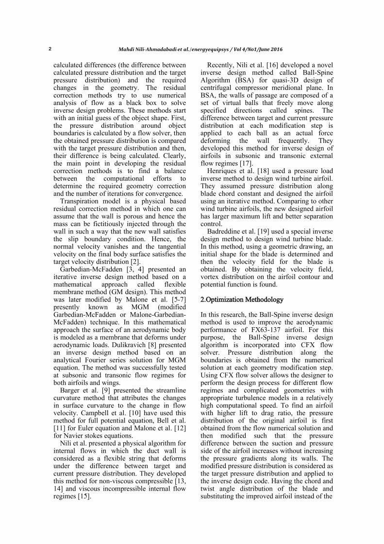
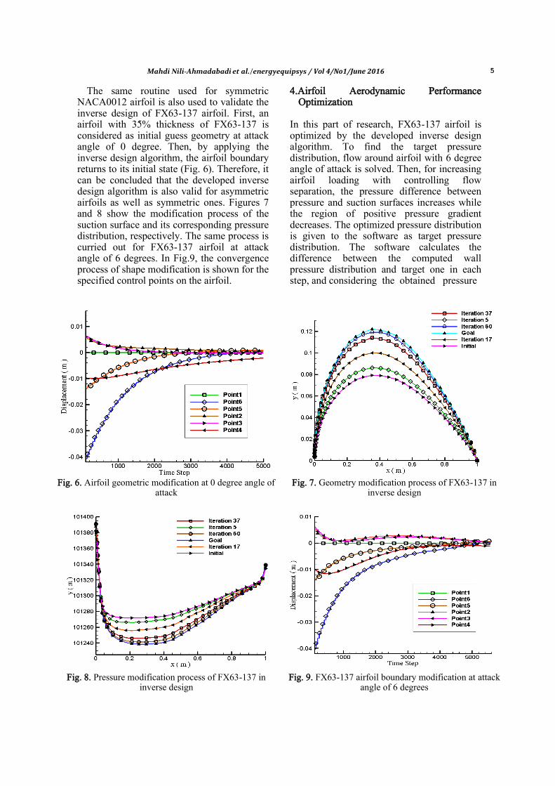
The same routine used for symmetric NACA0012 airfoil is also used to validate the inverse design of FX63-137 airfoil. First, an airfoil with 35% thickness of FX63-137 is considered as initial guess geometry at attack angle of 0 degree. Then, by applying the inverse design algorithm, the airfoil boundary returns to its initial state (Fig. 6). Therefore, it can be concluded that the developed inverse design algorithm is also valid for asymmetric airfoils as well as symmetric ones. Figures 7 and 8 show the modification process of the suction surface and its corresponding pressure distribution, respectively. The same process is curried out for FX63-137 airfoil at attack angle of 6 degrees. In Fig.9, the convergence process of shape modification is shown for the specified control points on the airfoil.
4.Airfoil Aerodynamic Performance Optimization
In this part of research, FX63-137 airfoil is optimized by the developed inverse design algorithm. To find the target pressure distribution, flow around airfoil with 6 degree angle of attack is solved. Then, for increasing airfoil loading with controlling flow separation, the pressure difference between pressure and suction surfaces increases while the region of positive pressure gradient decreases. The optimized pressure distribution is given to the software as target pressure distribution. The software calculates the difference between the computed wall pressure distribution and target one in each step, and considering the obtained pressure
Fig. 6. Airfoil geometric modification at 0 degree angle of
attack
Fig. 7. Geometry modification process of FX63-137 in inverse design
Fig. 8. Pressure modification process of FX63-137 in inverse design
Fig. 9. FX63-137 airfoil boundary modification at attack angle of 6 degrees

6 Mahdi Nili-Ahmadabadi et al./energyequipsys / Vol 4/No1/June 2016
difference, the profile boundaries are changed. This process is continued until the pressure difference becomes negligible. Through the modification process, some fluctuations may occur along the walls which can cause the inverse design to diverge. To overcome these fluctuations, airfoil boundaries should be smoothened after solution divergence. After each divergent step, the geometry fluctuations should be smoothed, again meshed and resolved. In each step, the initial guess geometry is considered as the last obtained geometry before diverging. For increasing the airfoil loading, the pressure distribution on the pressure side increases. In Fig.10, the target pressure of the pressure side obtained from load increasing is shown. As seen, after two times smoothing, the final pressure approaches to target one. Thus, with continuous smoothing of airfoil boundaries, the fluctuation problems could be solved. Figure 11 shows the geometry variations in optimization process.
The geometry obtained after two times smoothing (Fig. 11) is used as the new airfoil.
Lift and Drag coefficients, and for the new airfoil are computed using
,
(2)
,
(3)
(4)
and
, (5)
where L and D are the applied lift and drag forces on the airfoil, t is airfoil thickness, U is wind speed, α is angle of attack and C is airfoil chord length, respectively. Table 1, shows lift coefficient and lift to drag coefficient for the initial and optimized airfoils. As Table 1 shows, the lift coefficient of the new optimized airfoil is 5.5% larger than that of the FX63-137 airfoil. Furthermore, lift to drag ratio increases by 3.8%. Thus the new optimized airfoil has a higher loading compared to the FX63-137 airfoil.
Fig. 10. Airfoil pressure side pressure distribution at 6 degree angle of attack.
Fig. 11. Airfoil geometry variations
Table 1. Lift coefficient and lift to drag ratio for the initial guess and optimized airfoils
Airfoil
FX63-137 21.3178 1.44668
Optimized airfoil 24.2024 1.51975

Mahdi Nili-Ahmadabadi et al./energyequipsys / Vol 4/No1/June 2016 7
5.Wind Turbine Blade Aerodynamic Performance Optimization
Figure 12 shows chord distribution for wind turbine blade with FX63-137 airfoil. Figure 13 shows blade twist angle distribution along blade span. Considering chord length and twist angle (Figs. 12 and 13) and using the optimized airfoil instead of FX63-137, the new optimized wind turbine blade can be drawn (Fig. 14).
In this part, the numerical solution of flow around the 3-D blade with FX63-137 airfoil
and the optimized one is carried out to obtain and compare their aerodynamic performance. For this, a 120-degree sector solution domain is considered for numerical solution (Fig. 15). Using the frozen rotor method, solution domain is divided to stationary and rotating zones and utilizes relative motion between the various zones to transmit calculated values between zones. To complete the model in rotating zones, coriolis and centrifugal accelerations are added to momentum equations. In Fig.16, the rotating zone is shown.
Fig. 12. Blade chord distribution along blade span
Fig. 13. Blade twist angle distribution relative to its tip along blade span
Fig. 14. Generated 3-D blade of wind turbine
Fig. 15. Computational domains around wind turbine
Fig. 16. Rotational domain around the blade

8 Mahdi Nili-Ahmadabadi et al./energyequipsys / Vol 4/No1/June 2016
The most important step of the numerical simulation of flow around the blades is grid generation, which is usually the most time-consuming part. Selection of grid type and locations for grid refinements are additional important tasks. In this simulation, unstructured grid is used while for regions near the walls, structured grid is applied. The value of Y+ for the whole blade is smaller than 5, enough for boundary layer modeling. Total numbers of elements used for numerical domain are 3.8 million.
The flow pattern is analyzed using CFX flow solver. The Reynolds stress terms in the momentum transport equations are resolved using the shear-stress transport (SST) turbulence model, developed to blend the robust and accurate formulation of the k-ω model in the near-wall region with the free-stream independence of the k- ε model in the far field.
The boundary conditions used for the 3-D numerical simulation are similar to the 2-D one. Rotational speed of the wind turbine and wind speed is considered according to the design condition.
After analyzing the flow around the blades with FX63-137 and optimized airfoil, the pressure coefficient distributions for suction and pressure surfaces are obtained. Figures 17, 18 and 19 show pressure coefficient distributions at 30%, 50% and 80% blade span for the original and optimized blade, respectively. These figures clearly show that the pressure difference between suction and pressure sides of the blades with the optimized airfoil is larger than that of the blade with FX63-137 one and therefore, it is expected that the power increases.
Fig. 17. Pressure coefficient comparison of
blades with initial and optimized airfoil at 30% blade span
Fig. 18. Pressure coefficient comparison of blades
with initial and optimized airfoil at 50% blade span
Fig. 19. Pressure coefficient comparison of blades with initial and optimized airfoil at 80% blade
span
The turbine power coefficient can be calculated using
,
(6)
where A is the swept area by turbine blade. Table 2 shows the new wind turbine blade
torque and new turbine power factor. As shown, for turbine with optimized blade, the power coefficient is 0.4583 while for the turbine with FX63-137 blade, the power coefficient is 0.448. Thus, the blade power coefficient has increased by 3.2% and the blade aerodynamic performance has been improved.

Mahdi Nili-Ahmadabadi et al./energyequipsys / Vol 4/No1/June 2016 9
Table 2. The new blade applied torque and the new turbine power coefficient
Kg/m3(ρ) ѡ (Rad/Sec) A(m
2) Torque(N.m) Cp
1.185 12.32 24.66 -543.538 0.4583
6.Conclusions In this paper, first, Ball-Spine inverse design algorithm is developed for airfoil design in viscous turbulent flows by programming in CFX flow solver. Validation of the method is carried out for a symmetric airfoil and an asymmetric one. The results of validations show that in attack angles larger than 6 degrees, some fluctuations occur along the modifying boundary causing the program to be diverged. Thus, it is needed the walls be smoothed during each shape modification step. Having validated the inverse design process, the wall pressure distribution of FX63-137 airfoil is modified and applied to the inverse design method to reach an airfoil with a higher loading or higher lift to drag ratio. Finally, the highly loaded airfoil is considered as the section of a 3-D blade wind turbine. Having numerically analyzed the new 3-D blade and the original blade with FX63-137 airfoil, the aerodynamic performance of these two blades are obtained and then compared with each other. The results of 3-D numerical simulation show that the new blade has a higher power coefficient by 3.2% relative to the original blade. References [1] Stanitz J.D., Design of Two-Dimensional
Channels with Prescribed Velocity Distributions along the Duct Walls, Technical Report 1115, Lewis Flight Propulsion Laboratory (1953).
[2] Dedoussis V., Chaviaropoulos P., Papailiou K.D., Rotational Compressible Inverse Design Method for Two-Dimensional, Internal Flow Configurations, AIAA Journal, (1993) 31: 551-558.
[3] Garabedian P., McFadden G., Computational Fluid Dynamics of Airfoils and Wings. Journal Scientific Computing (1982)1-16.
[4] Garabedian P., McFadden G., Design of Supercritical Swept Wings. AIAA Journal (1982) 20:289-91.
[5] Malone J., Vadyak J., Sankar L., Inverse Aerodynamic Design Method for Aircraft
Components, Journal of Aircraft. (1987)24:8-9.
[6] Malone J., Vadyak J., Sankar L., A Technique for the Inverse Aerodynamic Design of Nacelles and Wing Configurations, AAIA Paper, AAIA-85-4096(1985).
[7] Malone J., Narramore J., Sankar L., An Efficient Airfoil Design Method Using the Navier–Stokes Equations, AGARD, Paper 5 (1989).
[8] Dulikravich G.S., Baker D.P., Using Existing Flow-Field Analysis Codes for Inverse Design of Three-Dimentional Aerodynamic Shapes. Recent Development of Aerodynamic Design Methodologies, (1999) 89-112 Springer.
[9] Barger R. L., Brooks C. W., A Streamline Curvature Method for Design of Supercritical and Subcritical Airfoils, NASA TN D-7770(1974).
[10] Campbell R.L., Smith L.A., A Hybrid Algorithm for Transonic Airfoil and Wing Design, AIAA Paper 87-2552 (1987).
[11] Bell R.A., Cedar R.D., An Inverse Method for the Aerodynamic Design of Three-Dimensional Aircraft Engine Nacelles (1991) (See Dulikravich 1991, 405-17).
[12] Malone J.B., Narramore J.C., Sankar L.N., An Efficient Airfoil Design Method Using the Navier-Stokes Equations (1989) (See AGARD 1989, Paper 5).
[13] Nili-Ahmadabadi M., Durali M., Hajilouy-Benisi A., Ghadak F., Inverse Design of 2-D Subsonic Ducts Using Flexible String Algorithm. Journal Inverse Problems in Science and Engineering. (2009) 17: 1037-57.
[14] Nili-Ahmadabadi M., Hajilouy A., Durali M., Ghadak F., Duct Design in Subsonic & Supersonic Flow Regimes with & without Shock Using Flexible String Algorithm, Proceedings of ASME Turbo Expo (2009) Florida, USA, GT2009-59744.
[15] Nili-Ahmadabadi M., Hajilouy-Benisi A., Ghadak F., Durali M., A Novel 2D Incompressible Viscous Inverse Design Method for Internal Flows Using Flexible String Algorithm, Journal of fluids engineering. (2010) 132.

10 Mahdi Nili-Ahmadabadi et al./energyequipsys / Vol 4/No1/June 2016
[16] Nili-Ahmadabadi M., Durali M., Hajilouy-Benisi A., A Novel Aerodynamic Design Method for Centrifugal Compressor Impeller, Journal of Applied Fluid Mechanics (2014) 7: 329-344.
[17] Nili Ahmadabadi M., Ghadak F., Mohammadi M., Subsonic and Transonic Airfoil Inverse Design via Ball-Spine Algorithm, Journal Computers & Fluids (2013).
[18] Henriques J.C.C., Marques da Silva F., Estanqueiro A.I., Gato L.M.C., Design of a New Urban Wind Turbine Airfoil Using a Pressure-Load Inverse Method. Renewable Energy (2009) 34:2728–2734.
[19]Kamouna B., Afungchuia D., Abid M., The Inverse Design of the Wind Turbine Blade Sections by the Singularities Method, Renewable Energy (2006) 31: 2091–2107.