excel 2-bag catcher 36/42/52 decks operator’s manual · 119649 1-1 rev d general information to...
TRANSCRIPT

119649 REV D
Excel 2-Bag Catcher36"/42"/52" DecksOperator’s Manual
200 South Ridge Road • Hesston, Kansas • 67062

REV D 119649

119649 toc-1 REV D
Table of Contents
General Information . . . . . . . . . . . . . . . . . . . . . . . . . . . . . . . . . . . . . 1-1
To the New Owner . . . . . . . . . . . . . . . . . . . . . . . . . . . . . . . . . . . 1-1Using This Manual . . . . . . . . . . . . . . . . . . . . . . . . . . . . . . . . . . . 1-1Warranty Registration. . . . . . . . . . . . . . . . . . . . . . . . . . . . . . . . . 1-1Parts and Service . . . . . . . . . . . . . . . . . . . . . . . . . . . . . . . . . . . . 1-1
Safety Precautions. . . . . . . . . . . . . . . . . . . . . . . . . . . . . . . . . . . . . . 2-1
Safe Operation and Service Precautions . . . . . . . . . . . . . . . . . . 2-1Safety and Instruction Decals. . . . . . . . . . . . . . . . . . . . . . . . . . . 2-2
Assembly Instruction . . . . . . . . . . . . . . . . . . . . . . . . . . . . . . . . . . . . 3-1
Required Tools . . . . . . . . . . . . . . . . . . . . . . . . . . . . . . . . . . . . . . 3-1Parts List . . . . . . . . . . . . . . . . . . . . . . . . . . . . . . . . . . . . . . . . . . 3-1Assembly . . . . . . . . . . . . . . . . . . . . . . . . . . . . . . . . . . . . . . . . . . 3-2
Operation . . . . . . . . . . . . . . . . . . . . . . . . . . . . . . . . . . . . . . . . . . . . . 4-1
Vacuum Pickup and Collection. . . . . . . . . . . . . . . . . . . . . . . . . . 4-1Unloading the Catcher Bags . . . . . . . . . . . . . . . . . . . . . . . . . . . 4-2Transporting Mower With Catcher . . . . . . . . . . . . . . . . . . . . . . . 4-3Converting To Side Discharge Mode . . . . . . . . . . . . . . . . . . . . . 4-3
Maintenance & Storage . . . . . . . . . . . . . . . . . . . . . . . . . . . . . . . . . . 5-1
Maintenance. . . . . . . . . . . . . . . . . . . . . . . . . . . . . . . . . . . . . . . . 5-1Storage. . . . . . . . . . . . . . . . . . . . . . . . . . . . . . . . . . . . . . . . . . . . 5-2
2-Bag Catcher Warranty Policy . . . . . . . . . . . . . . . . . . . . . . . . . . . . 6-1
Parts Manual . . . . . . . . . . . . . . . . . . . . . . . . . . . . . . . . . . . . . . . . . . 7-1

REV D toc-2 119649
119649 1-1 REV D
GENERAL INFORMATION
To the New Owner
The purpose of this manual is to assist owners andoperators in maintaining and operating the Excel Industries2-Bag Catcher. Please read it carefully; information andinstructions furnished can help you achieve years ofdependable performance.
Using This Manual
This manual contains general operation information aswell as basic adjustment and maintenance information.Since operating conditions vary considerably, all conditionscannot be addressed individually. Through training andexperience, operators should develop safe operatingpractices suitable to most conditions.
Directions used in this manual, for example RIGHT or LEFT,refer to directions when in the operator position and facingforward, unless otherwise stated.
Though current at the time of printing, photographs andillustrations shown may vary slightly from your mower due tosubsequent production changes. Excel Industries, Inc.reserves the right to redesign and change the machine asdeemed necessary, without notification. If a change has beenmade to your machine which is not reflected in this manual,contact your Excel Dealer for current information.
Warranty Registration
Your Dealer must register this attachment on-line withinten (10) days following date of purchase to validate yourwarranty protection. As the new equipment owner, you
should confirm that your Dealer has registered yourattachment with Excel Industries, Inc., manufacturer ofHustler® Turf Equipment, Inc. and BigDog® mowers(“Manufacturer”).
The mower and any attachment that displays a model andserial identification number plate must be registered withExcel Industries, Inc., manufacturer of Hustler® TurfEquipment, Inc. and BigDog® mowers (“Manufacturer”).Failure to register the attachment can void the warranty.
IMPORTANT: Any unauthorized modification, alteration, oruse of non-approved attachments voids the warranty andreleases Manufacturer and Hustler® Turf Equipment, Inc. orBigDog® Mower Company from any liability arising fromsubsequent use of this equipment. Do not use or operate anyattachment not approved by Hustler® Turf Equipment, Inc. orBigDog® Mower Company.
Parts and Service
Use original Excel replacement, or parts that are equivalentin overall performance, that are available from your localExcel Dealer. For prompt, efficient service, always provide thefollowing information when ordering parts:
1. Correct part description.
2. Correct part number.
3. Correct model number.
4. Correct serial number.
All arrangements for warranty repair and service must behandled through an authorized Excel Dealer.

REV D 1-2 119649
119649 2-1 REV D
SAFETY PRECAUTIONS
This safety alert symbol is used to call attention to amessage intended to provide a reasonable degree ofPERSONAL SAFETY for operators and other persons duringthe normal operation and servicing of this equipment.
This manual uses two other words to highlight information.IMPORTANT calls attention to special mechanicalinformation and NOTE emphasizes general informationworthy of special attention.
All operators and mechanics should read this manual, andbe instructed about safe operating and maintenanceprocedures.
Improper use or maintenance by the operator or owner canresult in injury. To reduce the potential for injury, comply withthese safety instructions and always pay attention to thesafety alert symbol “”, which means DANGER or WARNING- “personal safety instructions.” Failure to comply with theinstructions may result in personal injury or death.
Incorrect usage of this attachment may result in severeinjury. Personnel operating and maintaining it should be trainedin the proper use and should read the manuals completely andthoroughly before attempting to set-up, operate, adjust, orservice this mower.
Safe Operation and Service Precautions
Evaluate the terrain to determine what accessoriesand attachments are needed to properly and safelyperform the job. Only use accessories andattachments approved by the manufacturer.
Never use the catcher with Flex Forks® installed on themower.
Before proceeding:
• Park the mower on level ground.
• Disengage the deck clutch.
• Place the steering control levers in the park brakeposition.
• Stop the engine.
• Remove the ignition key.
• Wait for the engine and all moving parts to cometo a complete stop.
Always be aware of any obstructions, especially smallchildren, when backing or unloading the bags.
Always keep safety shields and covers in place, exceptfor servicing.
Never work on the mower deck when the mower’sengine is running.
Never operate machine with bagger lid in the raisedposition except for unloading.
Never attempt high speed maneuvering in crowded orcongested areas.
Only use the weights, furnished with the catcher, whenusing the catcher on this mower. Never operate themower with the catcher mounted and the weights notinstalled. Make sure the weights are properly installedand secured.
Always be aware that the catcher hangs off the rear ofthe mower, thereby increasing the length of themower. Use caution when backing up or turning whenthe catcher is mounted to the mower.
When the catcher is used, any rapid movement of thecontrol levers in either direction could result in areaction of the mower that can cause serious injury.
Always operate with complete catcher system,mulching system or side discharge chute in place andin the lowest position.
Never operate the mower with the catcher systeminstalled without the bags being properly installed andthe catcher lid in the lowered position.
Always keep clear of the mower blades andattachments during their operation.
Turn off the blades when not mowing.
– denotes immediate hazards which WILL result insevere personal injury or death.
– denotes a hazard or unsafe practice which COULDresult in severe personal injury or death.
DAN
GER
WAR
NIN
G

REV D 2-2 119649
Stop the engine before removing the grass catcher orunclogging the discharge chute. Never clear thedischarge chute with the engine running. Turn off theengine and be sure the blades have stopped beforecleaning. Use a stick to clear a plugged dischargearea. Never use your hand!
Clean flammable material from the machine. Preventfires by keeping the engine compartment, exhaust area,battery, fuel line, fuel tank and operator’s station clean ofaccumulated trash, grass clippings, and other debris.Always clean up spilled fuel and oil.
Grass collection system components are subject towear, damage and deterioration, which could exposemoving parts or allow objects to be thrown. Frequentlycheck components and replace with manufacturer’srecommended parts when necessary.
Never direct discharged material toward anyone. Avoiddischarging material against a wall or obstruction.Material may ricochet back toward the operator.Always disengage the blades and wait for them to stopbefore crossing gravel drives, walks or roads.
Safety and Instruction Decals
The decals are designed to give the operator briefinformation needed in the daily operation and service of themower. These decals are not intended to be used in place ofthis manual but instead are to be used as an extension ofthis manual. These decals should not be removed orobliterated. Replace these decals if they become unreadable.
• It is the owner’s responsibility to make certain that theoperators and mechanics read and understand thismanual and all decals before operating this mower.
• It is also the owner’s responsibility to make certain thatthe operators and mechanics are qualified andphysically able individuals, properly trained in theoperation of this equipment.
• All operators and mechanics must become familiarwith the safe operation of the equipment, operatorcontrols and decals.
• Never let children or untrained people operate orservice the equipment. Local regulations may restrictthe age of the operator.
• The owner/user can prevent and is responsible foraccidents or injuries occurring to themselves, otherpeople or property.
• The owner should also ensure that the operators/mechanics know that they are responsible for theirown safety as well as the safety of other personswithin the vicinity. Remember, the operator isresponsible for accidents or hazards occurring toother people or their property.
Refer to the mower’s operator’s manual for illustrationsshowing the various safety decals that are located on themower. A brief explanation, for those requiring one, is shownto help the operator understand the meanings of thesedecals.
Specific safety warning decals are located on theequipment near the immediate areas of potentialhazards. These decals should not be removed orobliterated. Replace them if they become non-read-able.
• Read Operator’s Manual and Safety Warning Decals before attempting to operate this machine.
• Under normal usage this bag material is subject to deteriora-tion and wear, and should therefore be frequently checked for bag replacement.
WAR
NIN
G
119649 2-3 REV D
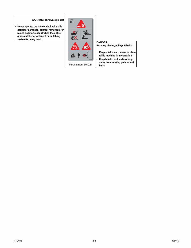
WARNING:Thrown objects!
• Never operate the mower deck with side deflector damaged, altered, removed or in raised position, except when the entire grass catcher attachment or mulching system is being used.
Part Number 604221
DANGER:Rotating blades, pulleys & belts
• Keep shields and covers in place while machine is in operation
• Keep hands, feet and clothing away from rotating pulleys and belts.
604221

REV D 2-4 119649

119649 3-1 REV D
ASSEMBLY INSTRUCTION
These instructions apply to the assembly of the Excel2-Bag Catcher on the following mowers:
Hustler® Raptor® 36"/42"/52"
BigDog® Alpha 36"/42"/52"
It is intended that these units be installed by trained Excelservice personnel. If additional assistance is required,contact the Excel Customer Service Department.
Directions given in these instructions, for example LEFTand RIGHT, refer to direction while seated on the mower.
Before proceeding, read through the following instructionsto familiarize yourself, while at the same time identify andinventory kit parts supplied.
Unpack and inspect all parts. Notify carrier of any shippingdamages immediately.
Required Tools
The following is a list of the tools required to assemble thecatcher to the mower.
• Tape measure
• One 3/8” combination wrench or socket
• One 1/2" combination wrench or socket
• Two 9/16" combination wrench or socket
• Torque wrench (with 48 ft-lb. range) with a 5/8" hexsocket
Parts List
NOTE: Refer to the Parts Manual section (starting on page7-1) of this manual for more detailed parts information.
PART NO. DESCRIPTION QTY.N/A 2 BAG LID 1
N/A CATCHER CHUTE 1
N/A 1.6 BUSHEL BAG 2
603848 BLADE, 17.86"-CAT-F-CW (36"/52" DECK) 1
793935 BLADE, 20.50"-CAT-F-CW (42" DECK) 1
117394 CATCHER FRAME 1
604387 UPPER CHUTE 1
604375 WEIGHT 2
604301 TIE ROD 2
117303 LS SUPPORT GUSSET 1
117304 RS SUPPORT GUSSET 1
117307 WEIGHT SUPPORT 1
117309 WEIGHT HOLD DOWN 1
117690 RS LEG MOUNT 1
117691 LS LEG MOUNT 1
792002 KNOB 5/16-18 X 3/4" 1
029629 CS .375-16 X .75 HX FLK 8
016899 NUT .375-16 HX FLK ZNYC 8
086660 NUT .375-16 HX ZY NL 2
037887 CB .312-18 X 1.00 5
768523 FW .343 X .687 X .051/.080H 5
058776 NUT .312-18 HX ZY NL 2
023036 HAIR PIN .148 X 2.69 ZN 2
604887 CE .375 x 3.00 WITH BALE 2
604806 PLASTIC CAP - TANK 1
000331 WIRE TIE 2
120864 LATCH SUPPORT 1
025395 CB .375-16 X 1.00G5 ZNY 4
054502 NT .375-16 HX G5 ZNY 4
068551 NT .25-20 HX ZY NL 3
604475 ELASTIC STRAP 3
704916 CS .250-20 X 1.25 HX G5 3
767954 FW .379 X .813 X .063 SAE 4
768515 FW .281 X .625 X .051/.080 HD ZN/YL 6
REV D 3-2 119649
Assembly
NOTE: Do not remove the mower’s discharge chute. Thedischarge chute does not need to be removed when attachingthis catcher to the mower.
1. Before proceeding:
• Park the mower on level ground.
• Disengage the deck clutch.
• Place the steering control levers in the park brakeposition.
• Stop the engine.
• Remove the ignition key.
• Wait for the engine and all moving parts to come to acomplete stop.
• Disconnect the negative battery cable.
2. Raise the front of the mower and deck up until theblades can be accessed easily. Place the mower onjack stands and do not allow the mower to move.Chock the rear wheels.
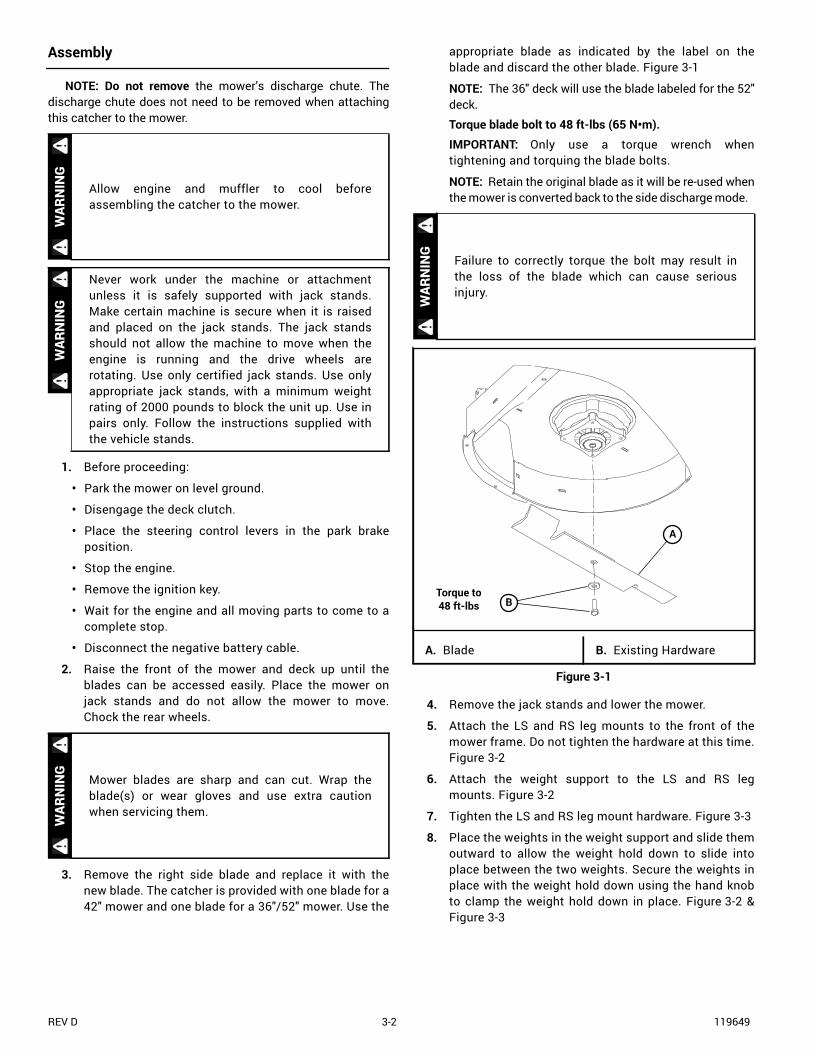
3. Remove the right side blade and replace it with thenew blade. The catcher is provided with one blade for a42" mower and one blade for a 36"/52" mower. Use the
appropriate blade as indicated by the label on theblade and discard the other blade. Figure 3-1
NOTE: The 36" deck will use the blade labeled for the 52"deck.
Torque blade bolt to 48 ft-lbs (65 N•m).
IMPORTANT: Only use a torque wrench whentightening and torquing the blade bolts.
NOTE: Retain the original blade as it will be re-used whenthe mower is converted back to the side discharge mode.
4. Remove the jack stands and lower the mower.
5. Attach the LS and RS leg mounts to the front of themower frame. Do not tighten the hardware at this time.Figure 3-2
6. Attach the weight support to the LS and RS legmounts. Figure 3-2
7. Tighten the LS and RS leg mount hardware. Figure 3-3
8. Place the weights in the weight support and slide themoutward to allow the weight hold down to slide intoplace between the two weights. Secure the weights inplace with the weight hold down using the hand knobto clamp the weight hold down in place. Figure 3-2 &Figure 3-3
Allow engine and muffler to cool beforeassembling the catcher to the mower.
Never work under the machine or attachmentunless it is safely supported with jack stands.Make certain machine is secure when it is raisedand placed on the jack stands. The jack standsshould not allow the machine to move when theengine is running and the drive wheels arerotating. Use only certified jack stands. Use onlyappropriate jack stands, with a minimum weightrating of 2000 pounds to block the unit up. Use inpairs only. Follow the instructions supplied withthe vehicle stands.
Mower blades are sharp and can cut. Wrap theblade(s) or wear gloves and use extra cautionwhen servicing them.
WAR
NIN
GW
ARN
ING
WAR
NIN
G
Failure to correctly torque the bolt may result inthe loss of the blade which can cause seriousinjury.
A. Blade B. Existing Hardware
Figure 3-1
WAR
NIN
G
A
Torque to 48 ft-lbs B

119649 3-3 REV D
A. LS Leg mountB. RS Leg mountC. Weight supportD. WeightsE. Weight hold down
F. KnobG. CB .312-18 X 1.00H. CS .375-16 X.75I. FW .343J. NT .312-18 NLK. NT .375-16 HXFLK
Figure 3-2
A. LS Leg mountB. RS Leg mountC. Weight support
D. WeightE. Weight hold downF. Knob
Figure 3-3
K
H I
J
G
F
CJ
I
A
E
D
B
F
C
AE
D
B
REV D 3-4 119649
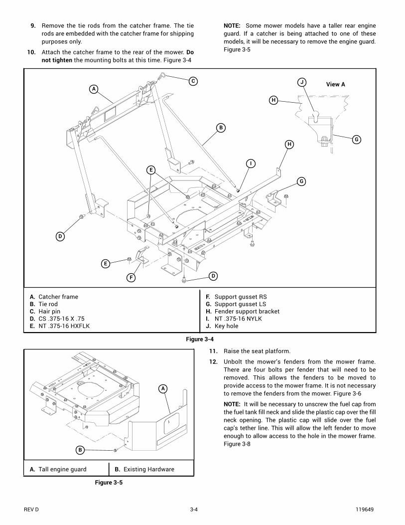
9. Remove the tie rods from the catcher frame. The tierods are embedded with the catcher frame for shippingpurposes only.
10. Attach the catcher frame to the rear of the mower. Donot tighten the mounting bolts at this time. Figure 3-4
NOTE: Some mower models have a taller rear engineguard. If a catcher is being attached to one of thesemodels, it will be necessary to remove the engine guard.Figure 3-5
11. Raise the seat platform.
12. Unbolt the mower’s fenders from the mower frame.There are four bolts per fender that will need to beremoved. This allows the fenders to be moved toprovide access to the mower frame. It is not necessaryto remove the fenders from the mower. Figure 3-6
NOTE: It will be necessary to unscrew the fuel cap fromthe fuel tank fill neck and slide the plastic cap over the fillneck opening. The plastic cap will slide over the fuelcap’s tether line. This will allow the left fender to moveenough to allow access to the hole in the mower frame.Figure 3-8
A. Catcher frameB. Tie rodC. Hair pinD. CS .375-16 X .75E. NT .375-16 HXFLK
F. Support gusset RSG. Support gusset LSH. Fender support bracketI. NT .375-16 NYLKJ. Key hole
Figure 3-4
D
G
I
G
F
H
J
H
View A
E
D
B
CA
E
A. Tall engine guard B. Existing Hardware
Figure 3-5
A
B

119649 3-5 REV D
NOTE: It is not necessary to remove the control panelfrom the right fender. There should be sufficient accessto the frame with the fender loose.
13. Attach the support gussets to the mower frame. Theslots in the support gussets must align with thekeyhole slots in the fender support bracket. Assemblethe hardware as shown with the cap screw insertedfrom the bottom. Figure 3-4 View A
IMPORTANT: Be sure not to cut or pinch the fuel linewhen installing gussets.
14. Thread a .375-16 nylon locking nut onto each of the tierods to the dimension shown in Figure 3-4 &Figure 3-7.
15. Insert one tie rod through the key hole slot in thefender support bracket and into the slot in the supportgusset. Make sure the nut on the tie rod is insertedthrough the slot in the support gusset. Figure 3-4 &Figure 3-9
The nut end of the tie rod can be easily insertedthrough the upper end of the slot if positionedhorizontally then angled upwards after the nut clearsthe support gusset. Figure 3-4 & Figure 3-9
IMPORTANT: Be certain that the nut does not catch orpinch the vapor line.
Then, insert the tie rod through the proper hole in thecatcher frame and secure with a hair pin. Figure 3-4
Repeat for the other side.
When performing this step heed the warningslisted below:
• Do not smoke while the fuel cap is notproperly secured to the fuel tank fill neck.Extinguish all cigarettes, cigars, pipes andother sources of ignition.
• Use extreme care when handling gasolinewhich is extremely flammable and vapors areexplosive. A fire or explosion from fuel canburn you and others and can damageproperty.
• Do not remove the fuel cap with engine runningor while engine is hot. Clean up any fuel spills.
• If fuel is spilled on clothing, change clothingimmediately.
A. Remove these bolts B. Fender
Figure 3-6
WAR
NIN
G
A
B
B
A A. Tie rod B. NT .375-16 NYLK
Figure 3-7
BA
1" ± 1/16"(19 mm)

REV D 3-6 119649
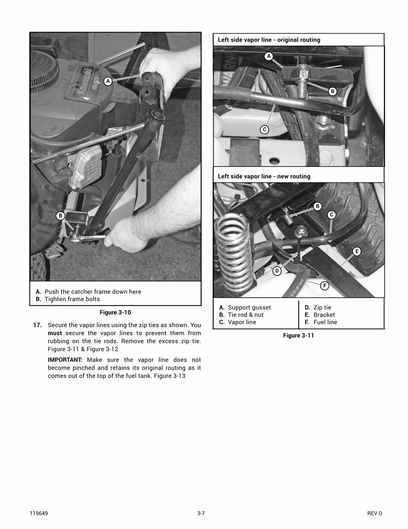
16. Push down on the catcher frame and tighten the lowerframe bolts. Pushing down on the catcher frame whiletightening these bolts will provide the correct tensionon the tie rods. Figure 3-10
A. Fill neckB. Fuel capC. Tether
D. Plastic capE. Fuel tankF. Fender
Figure 3-8
A
B
C
D
B
C
D
F
EA. Tie rodB. Mower frame
C. KeyholeD. NT .375-16 NYLKE. Support Gusset
Figure 3-9
Then, angle the tie rod to secure the nut against the support gussets.
Insert the tie rod through the keyhole as shown.
D
E
A
A
B
C
119649 3-7 REV D
17. Secure the vapor lines using the zip ties as shown. Youmust secure the vapor lines to prevent them fromrubbing on the tie rods. Remove the excess zip tie.Figure 3-11 & Figure 3-12
IMPORTANT: Make sure the vapor line does notbecome pinched and retains its original routing as itcomes out of the top of the fuel tank. Figure 3-13
A. Push the catcher frame down hereB. Tighten frame bolts
Figure 3-10
B
A
Left side vapor line - original routing
Left side vapor line - new routing
A. Support gussetB. Tie rod & nutC. Vapor line
D. Zip tieE. BracketF. Fuel line
Figure 3-11
A
B
C
BC
F
D
E

REV D 3-8 119649
18. Re-attach the fenders to the mower frame. Do notovertighten the mounting hardware. Figure 3-6
19. Remove the plastic cap from the fill neck opening andscrew the fuel cap onto the fill neck. Figure 3-8
20. Attach the latch support to the catcher frame asshown in Figure 3-14.
NOTE: If the four (4) mounting holes are not present inthe catcher frame, locate and drill four (4) .406" diameterholes in the frame per Figure 3-14.
21. Attach the elastic strap to the latch support. Orient theelastic strap as shown. Figure 3-14
Right side vapor line - original routing
Right side vapor line - new routing
A. Support gussetB. Tie rod & nutC. Vapor line
D. Zip tieE. Throttle cable
Figure 3-12
A
B
C
C
E
D
B
A. Vapor lineB. Zip tie
C. Fuel line
Figure 3-13
Never operate the mower without the fuel capthreaded tightly onto the fill neck.
C
B
A
WAR
NIN
G

119649 3-9 REV D
A. Catcher lidB. Latch supportC. Elastic strapD. CS .250-20 X 1.25E. FW .281 X .625 X .0551/.080
F. NT .250-20G. CB .375-16 X 1.00H. FW .379 X .813 X .063I. NT .375-16
Figure 3-14
I
E
G
D
Section A-A
If the 4 mounting holes are not present in the frame, locate and drill four .406" diameter holes in the frame.
E
A
F
12.09" 12.09"
3.05"1.21"
.406" diameter holes (4 places)
H
C
B
A-A
REV D 3-10 119649
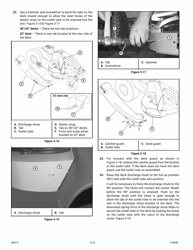
22. Use a hammer and screwdriver to bend the tabs on thedeck inward enough to allow the steel hooks of theelastic strap on the outlet tube to be inserted into theslot. Figure 3-16 & Figure 3-17
36"/42" decks – There are two tab locations.
52" deck – There is one tab located at the rear side ofthe deck.
23. For mowers with the deck guard, as shown inFigure 3-18, remove the catcher guard from the bottomof the outlet tube. If the deck does not have the deckguard, use the outlet tube as assembled.
24. Raise the deck discharge chute to the full up position(90o) and slide the outlet tube into position.
It will be necessary to force the discharge chute to the90o position. The chute will contact the mower fenderbefore the 90o position is attained. Push on thedischarge chute until the chute is open enough toallow the tab of the outlet tube to be inserted into theslot in the discharge chute bracket of the deck. Thedownward spring force of the discharge chute helps tosecure the outlet tube to the deck by locking the bumpon the outlet tube with the cams of the dischargechute. Figure 3-19
A. Discharge chuteB. TabC. Outlet tube
D. Elastic strapE. Tab on 36"/42" decksF. Front anti-scalp wheel
bracket on 52" deck
Figure 3-15
A. Discharge chute B. Tab
Figure 3-16
E
B
A
52" deck only
B
F
D
C
AB
A. TabB. Screwdriver
C. Hammer
Figure 3-17
A. Catcher guardB. Outlet tube
C. Deck guard
Figure 3-18
A
C
B
A
B
C

119649 3-11 REV D
Secure the outlet tube in place with the elastic latches.Figure 3-15
25. Slide the end of the transfer tube into the opening inthe catcher lid. Figure 3-20
26. Place the bags on the catcher frame by inserting thebag frame hook into the catcher frame slot.Figure 3-24
27. Attach the catcher lid to the catcher frame using theCE .375 x 3.00 with bale pins. Close the catcher lid.Figure 3-24
NOTE: It is easier for two people to attach the catcher lidto the catcher frame than it is for one person.
28. Attach the transfer tube to the outlet tube by aligningthe slot on the transfer tube with the knob on theoutlet tube and hooking the elastic latch through theloop of the transfer tube. Figure 3-21 & Figure 3-22 Outlet tube tab not installed correctly
Outlet tube tab installed correctly
A. Discharge chuteB. Discharge chute
bracket slotC. Outlet tube tab
D. Ridge on outlet tubeE. Cam of discharge
chute
Figure 3-19
A
B
C
A
B
C
E
D
A. Catcher lidB. Transfer tube
C. Outlet tubeD. Elastic latch
Figure 3-20
A. Transfer tube slotB. Outlet tube knob
C. Elastic latch
Figure 3-21
A
C
B
D
C
A
B

REV D 3-12 119649
29. Reconnect the negative battery cable.
A. Transfer tubeB. Outlet tube
C. Elastic latch
Figure 3-22
Do not operate deck without discharge chute orcomplete catcher system, including the weighttray and weight, in place.
C
A
B
WAR
NIN
G A. BagB. Bag frame hook
C. Catcher frame
Figure 3-23
C
B
A
A. Catcher lid B. CE .375 x 3.00 with bale pin
Figure 3-24
A
B
B

119649 4-1 REV D
OPERATION
Vacuum Pickup and Collection
Follow normal mower start-up and operating procedures asoutlined in the mower operator’s manual. Whenever the deckclutch switch is engaged there will be debris moving throughthe catcher system.
The following list contains useful information when usingthe catcher:
• When catching, use the left side of the mower fortrimming to prevent damage to the discharge chuteand outlet tube.
• Catching with the cutting height set too low mayprevent adequate air movement under the deck. Thiswill cause clogging of the catching system.
• During peak growing times it may be necessary to cutthe grass more often. If the grass is too long it mayneed to be cut twice. First, mow the grass with thecutting height set at a high setting to cut off the upperparts of the grass. Next, lower the cutting height to thepreferred finished cut height and mow the area again.This will help reduce clogging.
• To help reduce clogging mow by slightly overlappingthe previously cut area.
• Proceed to mow in the normal manner with the enginethrottle set to the “FAST” position. Control themower’s ground speed by using the steering controllevers. In tall and/or wet grass the high engine speedand slower ground speed will help prevent clogging.
• When catching on slopes mow going downhill whenpossible. It is necessary to reduce ground speed whenoperating on a slope.
• If debris begins to blow out in front of the outlet tubeor a trail of debris is visible along the right edge of thecutting path, either the catcher is full or the outlet tubeis clogged.
• As you mow visually check how full the bags are, whenthe right bag looks full move the deck clutch switch tothe disengaged position and drive the machine to theunloading area.
• It is best that the bags be unloaded before thedischarge chute and tube areas become clogged. Ifclogging occurs, it will be necessary to clean thedischarge chute and tube areas of all material beforestarting to mow again.
• When the grass is wet it may be necessary to mow itfirst in the side discharge mode. Then, after theclippings have dried, go back over the area with thecatcher installed and pick up the clippings.
• To minimize clogging, reduce your mowing speed asnecessary or wait until there is less moisture in thegrass.
Remember, as the bags fill more weight is addedto the back of the mower. Any rapid movement ofthe control levers in either direction could result ina reaction of the mower that can cause seriousinjury.
• Do not stop or start suddenly when mowingon slopes. Avoid uphill starts.
• Disengage the blades if you stop the mowerwhen going uphill and proceed to back offthe slope slowly.
• Maintain an even mowing speed whenoperating on slopes.
• Do not stop on a slope.
• Never operate the mower with the catcherattached on a slope without the frontweights installed and securely fastened.
WAR
NIN
G
Prevent objects being thrown and theaccumulation of grass clippings and other debrisin engine compartment by NEVER operating themower deck unless:
• Both bags are installed.
• Catcher lid is lowered.
• Outlet tube is in place and secured on thedischarge chute outlet and deck.
• Transfer tube is secured in place, with theelastic strap, on the outlet tube and isinserted into the catcher lid.
Make certain the engine is turned off, the steeringcontrol levers are in the park brake position andthe ignition key is removed from the ignitionswitch. Be sure blades have stopped beforecleaning the discharge chute and transfer tubeareas.
Never place hands or feet into the discharge area.The mower blade is relatively close to the housingand will cause severe injury. Use a probe to cleandebris from the catcher outlet tube.
WAR
NIN
GW
ARN
ING
WAR
NIN
G

REV D 4-2 119649
Unloading the Catcher Bags
Get off the mower. Unlatch and raise the catcher lid.Remove the bag by lifting the bag frame at the rear of the bagand the bag frame handle. Proceed to dump the bag.Figure 4-2 & Figure 4-3
Return the bags to the catcher frame and close the catcherlid. Secure the lid using the elastic strap. Figure 4-3
Never engage the mower deck unless the catchertransfer tube is secured in place, with the elasticstrap on the outlet tube, and is inserted into thecatcher lid. Figure 4-1
A. Catcher lidB. Transfer tube
C. Elastic latchD. Outlet tube
Figure 4-1
Park the unit on a level surface, disengage thedeck clutch switch, place the steering controllevers in the park brake position and shut theengine off. Make certain the deck clutch switch isin the disengaged position before unloading.
WAR
NIN
G
A
C
B
D
WAR
NIN
G
A. Catcher lidB. Bag frame
C. Catcher bagD. Bag frame handle
Figure 4-2
A. Catcher Frame B. Bag
Figure 4-3
A
B
D
C
A
B

119649 4-3 REV D
Transporting Mower With Catcher
When transporting the mower to another location with thecatcher attached, on an open trailer or vehicle, the catcherlid, bags, and tubes must be removed and secured in thetransporting vehicle to prevent them from being blown off.
Converting To Side Discharge Mode
Convert the mower back to the side discharge mode whencatching is not desired.
When converting to side discharge mode it will benecessary to remove the bags, tubes, and catcher lid fromthe mower. The catcher frame can remain in place on themower.
When converting to the side discharge mode it isnecessary to remove the right hand (catching) blade from themower. Replace it with the proper side discharge blade.Torque blade bolt to 48 ft-lbs (65 N•m). Figure 4-4
IMPORTANT: Only use a torque wrench when tighteningand torquing the blade bolts.
IMPORTANT: Make certain the discharge chute is loweredto the mowing position before mowing.
A. Blade B. Existing hardware
Figure 4-4
A
Torque to 48 Ft.-lbs.
B
Failure to correctly torque the bolt may result inthe loss of the blade which can cause seriousinjury.
Always operate with complete catcher system,mulching system or side discharge chute in placeand in the lowest position.
WAR
NIN
GW
ARN
ING

REV D 4-4 119649

119649 5-1 REV D
MAINTENANCE & STORAGE
Maintenance
Inspect the catcher after the initial use of the unit andevery month thereafter.
• Check for damaged or worn parts. Replace or repair alldamaged parts before operating with the catcheragain.
• Check for loose hardware. Tighten any hardware thatis loose.
• Inspect the tie straps and replace any that are missing,damaged or beginning to show signs of wear.
• Inspect and replace the bags if any deterioration hasoccurred.
The outlet tube and transfer tube should be kept clean andfree of any accumulation of matted clippings or otherobstructions.
To service the outlet tube and transfer tube, remove thetubes from the unit. The tubes can be cleaned by using soapywater and washing the inside of the tubes with a pressurewasher. Rinse with water.
To clean the bags, hand wash with soap and water; rinsewith clean water.
Never work on the mower deck when the engine isrunning.
Clean flammable material from machine.Prevent fires by keeping the enginecompartment, top of deck, exhaust area,battery, fuel line, fuel tank and operator’sstation clean of accumulated trash, grassclippings, and other debris. Always clean upspilled fuel and oil.
Severe injury can occur to the operator and/orbystanders or property damage may occur as theresult of flying debris or thrown objects due todamaged bags.
• Check bags for any signs of damage such astears, holes, wear or any deterioration.
• If a bag is found to be defective in any way,replace it with a new bag that is supplied byExcel Industries, Inc.
WAR
NIN
GW
ARN
ING
WAR
NIN
G
Prevent objects being thrown and theaccumulation of grass clippings and otherdebris in engine compartment by NEVERoperating the mower deck unless:
• Both bags are installed.• Catcher lid is lowered.• Outlet tube is in place and secured on
the discharge chute outlet and deck.Figure 5-1
• Transfer tube is secured in place, withthe elastic strap, on the outlet tube andis inserted into the catcher lid.Figure 5-1
A. Catcher lidB. Transfer tube
C. Elastic latchD. Outlet tube
Figure 5-1
WAR
NIN
G
A
C
B
D

REV D 5-2 119649
Storage
When your mower is to sit idle for a period of time, scrapeand remove the matted grass material from inside the hoodand clean the bags.
Check for loose or missing hardware, tighten or replace.Also check for badly worn or damaged parts, considerreplacing them at this time. Touch up chipped paint areas;your dealer has aerosol spray paint available.

119649 6-1 REV D
2-Bag Catcher Warranty Policy
Excel Industries, Inc. makes the following warranty to theoriginal purchaser only:
a. Excel Industries, Inc. attachments and accessories arewarranted for one (1) year (parts and labor) from date ofdelivery on all materials and workmanship. If the Purchaser discovers within this warranty period adefect in materials or workmanship:
• Purchaser must promptly notify an authorized dealerof the defect. In no event shall such notification be
received by an authorized dealer later than thirteen(13) months from date of delivery.
• Within a reasonable time after such notification,Excel Industries, Inc. will correct any defect inmaterial or workmanship on the Excel Industries, Inc.attachments and accessories, by repairing orreplacing part(s) with either new or used replacementparts.
• Such repair, including parts and labor shall be at theexpense of Excel Industries, Inc.
General Information
Who Must Perform The Warranty ServiceAll warranty service will be performed by Excel Industries, Inc.
or authorized dealers. Service calls and/or transportationexpense of the product to and from the authorized dealer, forwarranty work, will be paid by the owner of the product. Forwarranty service contact an authorized dealer.
What Is Not Covered By This WarrantyExcel Industries, Inc. does not warranty:
• Improper or incorrectly performed maintenance orrepair by unauthorized persons that causes damagesto the equipment.
• Damage caused by use of the Excel Industries, Inc.turf equipment for purposes other than those forwhich it was designed.
• Damages caused by disasters such as fire, flood,wind, and lightning.
• Damages caused by neglect, abuse, abnormal use,improper or unreasonable use, accident, negligenceor misuse.
• Repairs or replacement from damage resulting fromthe use of unauthorized accessories or attachments.
• Using replacement parts that are neither approved byManufacturer nor are equivalent in overallperformance. Damage caused by unauthorizedreplacement parts is not covered by this warranty.Manufacturer expressly excludes liability for defectsor damage caused by such 'unauthorized' articles orservice.
• Damage caused by foam filled or solid filled tires.
• Repairs or replacement as the result of alterations ormodifications.
• Excel Industries, Inc. turf equipment which has theserial number removed or made illegible.
• Depreciation or damage caused by normal wear, lackof reasonable and proper maintenance, failure tofollow the product’s operator’s manual operating,maintenance and adjustment instructions or otheroperational instructions provided by Excel Industries,Inc.
• Normal maintenance parts and service including, butnot limited to, lubricants, belts, blades, bladesharpening, or bearings.
Disclaimer Of WarrantyTHE FOREGOING WARRANTIES ARE IN LIEU OF ALL OTHER
WARRANTIES, EXPRESSED OR IMPLIED, INCLUDING BUT NOTLIMITED TO THE IMPLIED WARRANTIES OFMERCHANTABILITY AND FITNESS FOR A PARTICULARPURPOSE. HOWEVER, IF THE EXCEL INDUSTRIES, INC.ATTACHMENT OR ACCESSORY IS PURCHASED AS ACONSUMER PRODUCT, ANY IMPLIED WARRANTY OFMERCHANTABILITY OR FITNESS FOR A PARTICULARPURPOSE IS LIMITED TO THE DURATION OF THIS LIMITEDWARRANTY.
Some states do not allow limitations on how long an impliedwarranty lasts, so the above limitation may not apply to you.This warranty gives you specific legal rights, and you may alsohave other rights which vary from state to state.
Limitations Of WarrantiesIN NO CASE SHALL EXCEL INDUSTRIES, INC., OR ITS
AFFILIATES, BE LIABLE FOR ANY SPECIAL, INCIDENTAL, ORCONSEQUENTIAL DAMAGES BASED UPON BREACH OFWARRANTY, BREACH OF CONTRACT, NEGLIGENCE, STRICTLIABILITY IN TORT, OR ANY OTHER LEGAL THEORY.
Such damages include, but are not limited to:
• Loss of profits
• Loss of savings or revenue
• Loss of use of Excel Industries, Inc. turf equipment orany associated equipment

REV D 6-2 119649
• Cost of capital
• Cost of any substitute equipment, facilities, servicesor downtime
• The claims of third parties including customers, andinjury to property
Some states do not allow the exclusion or limitation ofincidental or consequential damages, so the above limitation orexclusion may not apply to you.
No Other WarrantiesUnless modified in writing, signed by both parties, and
approved by the President of Excel Industries, Inc., thisagreement is understood to be the complete and exclusiveagreement between the parties, superseding all prioragreements, oral or written, and all other communicationsbetween the parties relating to the subject matter of thisagreement. No employee of Excel Industries, Inc., or any otherparty is authorized to make any warranty in addition to thosemade in this agreement.
Allocation Of RisksThis agreement allocates the risks of product failure between
Excel Industries, Inc. on the one hand and the purchaser on theother. This allocation is recognized by both parties and isreflected in the price of the goods.
Owner’s ResponsibilityYou must maintain your Excel Industries, Inc. product
following the maintenance procedures described in youroperator's manual. Such routine maintenance, whetherperformed by a dealer or by you, is at your expense.
This attachment or accessory like any other equipment ispotentially dangerous unless properly operated. Any operatormust be cautious and keep safety in mind at all times. Anyoperator, prior to using the Excel Industries, Inc. turfequipment, should thoroughly familiarize himself with theoperator's manual regarding operation and safety of themachine, as well as all safety warnings on the machine itself.
Warranty Registration• Hustler® Dealers must register the attachment on-line at
https://dealer.hustlerturf.com within ten (10) days following date of purchase.
• BigDog® Dealers must register the attachment on-line at http://excel.warrantysmart.arinet.com within ten (10) days following date of purchase.
• Lowe’s® customers must register the attachment on-line at http://www.hustlerturf.com/raptor_warranty_registration within ten (10) days following date of purchase.
• The date of purchase constitutes delivery.
• Failure to register the attachment may void thewarranty.
Australia Special Information
The following information is for Australian consumers only.
The benefits to the consumer given by this warranty are in addition to other rights and remedies of the consumer under a law in relation to the goods or services to which this warranty relates.
Our goods come with guarantees that cannot be excluded under the Australian consumer law. You are entitled to a replacement or refund for a major failure and for compensation for any reasonable foreseeable loss or damage. You are also entitled to have the goods repaired or replaced if the goods fail to be of acceptable quality and the failure does not amount to a major failure.
Powerup Lawncare Products11 Sodium St.Narangba, Qld 4504Telephone 1300 363 027

119649 7-1 REV D
PARTS MANUAL
Catcher Frame. . . . . . . . . . . . . . . . . . . . . . . . . . . . . . . . . . . . . . . . . 7-2
Catcher Lid—552396. . . . . . . . . . . . . . . . . . . . . . . . . . . . . . . . . . . . 7-4
Catcher Chute & Blades—Decks with Guard . . . . . . . . . . . . . . . . . 7-6
Catcher Chute & Blades—Decks without Guard . . . . . . . . . . . . . . . 7-8
Catcher Bag Assembly—552460. . . . . . . . . . . . . . . . . . . . . . . . . . 7-10
REV D 7-2 119649
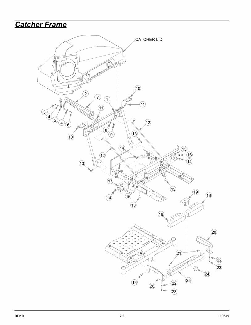
Catcher Frame
6
21
3
10
8
12
13
1215
1614
13
13
17
18
18
20
2122
23
22
23
2425
14
1326
CATCHER LID
45 4
10 9
14
13
14 1619
7
1111

119649 7-3 REV D
Catcher Frame
NOTES:
INDEX NO. PART NO. QTY. DESCRIPTION
1 117394 1 CATCHER FRAME2 120864 1 LATCH SUPPORT3 068551 1 NT .250-20 HX ZY NL4 768515 2 FW .281 X .625 X .0665 604475 1 BUNGEE LATCH6 704916 1 CS .250-20 X 1.25 HX G57 025395 4 CB .375-16 X 1.00 G5 ZNY8 767954 4 FW .379 X .813 X .0639 054502 4 NT .375-16 HX G510 604887 2 CE .375 X 3.00 WITH BALE11 023036 2 HP .148 X 2.69 ZN12 604301 2 TIE ROD13 029629 8 CS .375-16 X .75 HX FLK14 016899 8 NT .375-16 HX G5 FLK15 117303 1 LS SUPPORT GUSSET16 086660 2 NT .375-16 HX G5 NL17 117304 1 RS SUPPORT GUSSET18 604375 2 WEIGHT19 117309 1 WEIGHT HOLD DOWN20 117691 1 LS LEG MOUNT21 037887 2 CB .312-18 X 1.00 FULL ZN22 768523 2 FW .343 X .687 X .051/.080H23 058776 2 NT .312-18 HX G5 ZY NL24 792002 1 KNOB 5/16-18 X 3/4"25 117307 1 WEIGHT SUPPORT26 117690 1 RS LEG MOUNT

REV D 7-4 119649
Catcher Lid—552396
1210
10
11
9 10
10
1
2
3
88
4
8
4
6
7
5
4
16
16
17
13
1516
18
1416
18

119649 7-5 REV D
Catcher Lid—552396
NOTES:
INDEX NO. PART NO. QTY. DESCRIPTION
1 603398 6 RIVET2 117501 1 CATCHER INLET3 604394 1 INLET SEAL4 603400 13 FW .188 X .50 X .0605 552396 1 CATCHER LID (COMPLETE ASSEMBLY)6 117678 1 VENT MOUNT BRACKET7 117584 1 BAG DIVIDER8 604805 7 BLIND RIVET9 064329 3 CS .250-20 X .625 HX G5
10 768515 6 FW .281 X .625 X .051/.080 HD ZN/YL11 118562 1 DEBRIS GUIDE12 068551 3 NT .250-20 HX ZY NL13 120884 1 STIFFENER PLATE14 120882 1 HINGE BRACKET RS15 120883 1 HINGE BRACKET LS16 768523 8 FW .343 X .687 X .051/.080H17 036236 4 CS .312-18 X 1.00 HX G518 034272 4 NT .312-18 HX G5 ZNYC

REV D 7-6 119649
Catcher Chute & Blades—Decks with Guard
3
2
4
5
64
43
464
5
4
3
1
5
7
EXISTINGHARDWARE 1
GUARD

119649 7-7 REV D
Catcher Chute & Blades—Decks with Guard
NOTES:
1. Torque to 48 ft.-lbs.
INDEX NO. PART NO. QTY. DESCRIPTION
1 604387 1 UPPER CHUTE2 604371 1 OUTLET TUBE3 068551 3 NT .250-20 HX ZY NL4 768515 6 FW .281 X .625 X .051/.080H5 604475 3 BUNGEE LATCH6 704916 3 CS .250-20 X 1.25 HX G57 793935 1 BLADE, 20.50"-CAT-F-CW (42" DECK)8 603848 1 BLADE, 17.86"-CAT-F-CW (36" & 52" DECKS)

REV D 7-8 119649
Catcher Chute & Blades—Decks without Guard
3
2
4
5
6
4
34
3
3
1
7
10
EXISTINGHARDWARE1
5
4
67
7
3
3
4
546
89
NO GUARD

119649 7-9 REV D
Catcher Chute & Blades—Decks without Guard
NOTES:
1. Torque to 48 ft.-lbs.
INDEX NO. PART NO. QTY. DESCRIPTION
1 604387 1 UPPER CHUTE2 604371 1 OUTLET TUBE3 068551 3 NT .250-20 HX ZY NL4 768515 6 FW .281 X .625 X .051/.080H5 604475 3 BUNGEE LATCH6 704916 3 CS .250-20 X 1.25 HX G57 017079 3 FW .250 X .56 X .04 SAE Z8 601503 3 CB .250-20 X .625 ZN9 124494-3 1 CATCHER GUARD10 793935 1 BLADE, 20.50"-CAT-F-CW (42" DECK)
603848 1 BLADE, 17.86"-CAT-F-CW (36" & 52" DECKS)
REV D 7-10 119649
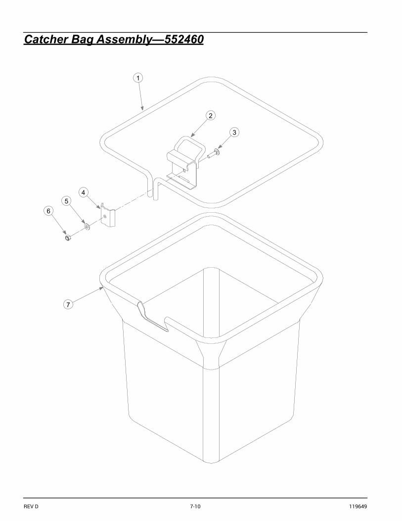
Catcher Bag Assembly—552460
2
1
4
3
65
7

119649 7-11 REV D
Catcher Bag Assembly—552460
NOTES:
INDEX NO. PART NO. QTY. DESCRIPTION
1 117393 1 BAG SUPPORT2 117390 1 BAG CATCH3 602827 1 CB .312-18 X 1.25 ZNYC4 117401 1 CLAMP BRACKET5 768523 1 FW .343 X .687 X .051/.080H6 058776 1 NT .312-18 HX ZY NL7 552460 1 CATCHER BAG ASSEMBLY (BAG INCL. ITEMS 1–6)

REV D 7-12 119649

119649 i-1 REV D
INDEXPAGE PAGE
Assembly .................................................................3-2
Converting To Side Discharge Mode .....................4-3
Maintenance ............................................................5-1
Parts and Service ....................................................1-1
Parts List ..................................................................3-1
Required Tools ........................................................3-1
Safe Operation and Service Precautions ..............2-1
Safety and Instruction Decals ................................2-2
Storage .................................................................... 5-2
To the New Owner ................................................. 1-1
Transporting Mower With Catcher Attached ........ 4-2
Unloading the Catcher Bags ................................. 4-2
Vacuum Pickup and Collection ............................. 4-1
Warranty Policy ...................................................... 6-1
Warranty registration ............................................. 1-1

REV D i-2 119649