excalibur - aw direct introduction the excalibur® light bar is a dual-level light bar that is...
TRANSCRIPT

INSTALLATION& OPERATION
MANUAL
EXCALIBUR® LIGHTBARS
Read all instructions and warnings before installing and using.INSTALLER: This manual must be delivered to the end user of this equipment.IMPORTANT:
EXCALIBUR ®
DUAL LEVEL LIGHT BAR
Introduction...................................................................................2Unpacking & Pre-Installation.........................................................3Installation & Mounting..........................................................3-5Wiring Instructions.................................................................5-6Options & Specifications........................................................6-8Maintenance...........................................................................8-12Parts List (Replacement Parts / Exploded View).................13-16Trouble Shooting.................................................................17-18Notes..................................................................................................19Warranty.....................................................................................20
CONTENTS:
For future reference record your lightbar's serial no. here __________________________________________
2
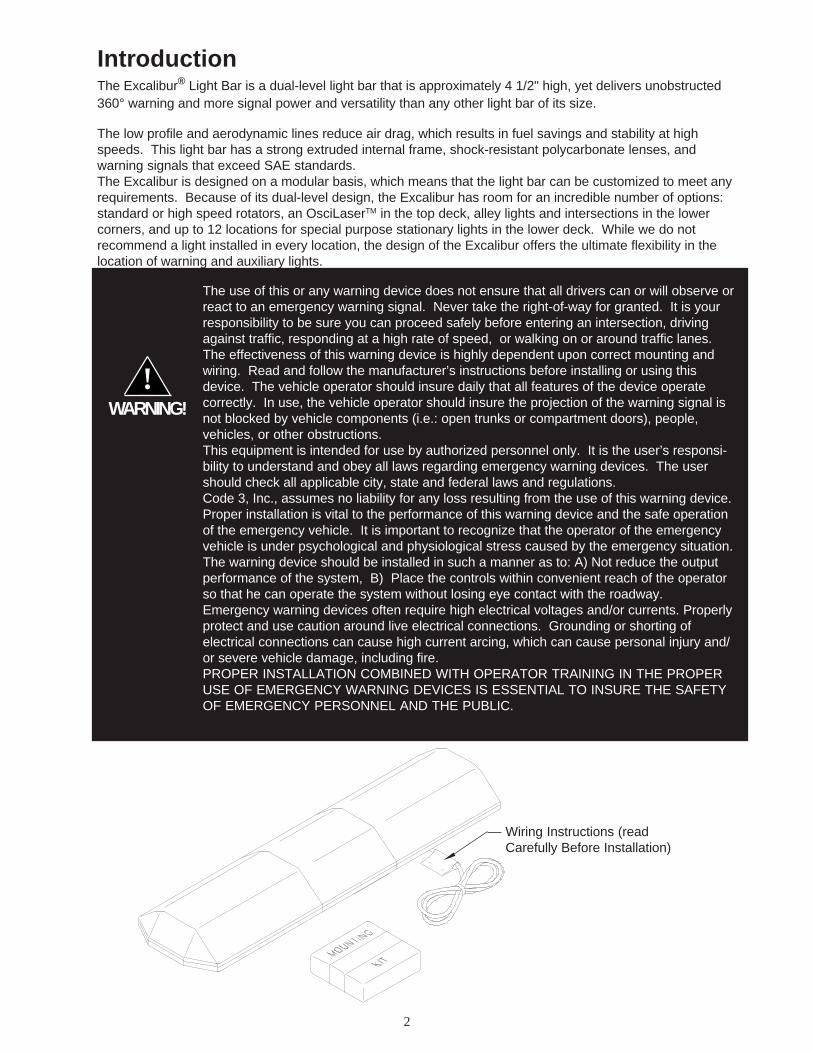
IntroductionThe Excalibur® Light Bar is a dual-level light bar that is approximately 4 1/2" high, yet delivers unobstructed360° warning and more signal power and versatility than any other light bar of its size.
The low profile and aerodynamic lines reduce air drag, which results in fuel savings and stability at highspeeds. This light bar has a strong extruded internal frame, shock-resistant polycarbonate lenses, andwarning signals that exceed SAE standards.The Excalibur is designed on a modular basis, which means that the light bar can be customized to meet anyrequirements. Because of its dual-level design, the Excalibur has room for an incredible number of options:standard or high speed rotators, an OsciLaserTM in the top deck, alley lights and intersections in the lowercorners, and up to 12 locations for special purpose stationary lights in the lower deck. While we do notrecommend a light installed in every location, the design of the Excalibur offers the ultimate flexibility in thelocation of warning and auxiliary lights.
The use of this or any warning device does not ensure that all drivers can or will observe orreact to an emergency warning signal. Never take the right-of-way for granted. It is yourresponsibility to be sure you can proceed safely before entering an intersection, drivingagainst traffic, responding at a high rate of speed, or walking on or around traffic lanes.The effectiveness of this warning device is highly dependent upon correct mounting andwiring. Read and follow the manufacturer’s instructions before installing or using thisdevice. The vehicle operator should insure daily that all features of the device operatecorrectly. In use, the vehicle operator should insure the projection of the warning signal isnot blocked by vehicle components (i.e.: open trunks or compartment doors), people,vehicles, or other obstructions.This equipment is intended for use by authorized personnel only. It is the user’s responsi-bility to understand and obey all laws regarding emergency warning devices. The usershould check all applicable city, state and federal laws and regulations.Code 3, Inc., assumes no liability for any loss resulting from the use of this warning device.Proper installation is vital to the performance of this warning device and the safe operationof the emergency vehicle. It is important to recognize that the operator of the emergencyvehicle is under psychological and physiological stress caused by the emergency situation.The warning device should be installed in such a manner as to: A) Not reduce the outputperformance of the system, B) Place the controls within convenient reach of the operatorso that he can operate the system without losing eye contact with the roadway.Emergency warning devices often require high electrical voltages and/or currents. Properlyprotect and use caution around live electrical connections. Grounding or shorting ofelectrical connections can cause high current arcing, which can cause personal injury and/or severe vehicle damage, including fire.PROPER INSTALLATION COMBINED WITH OPERATOR TRAINING IN THE PROPERUSE OF EMERGENCY WARNING DEVICES IS ESSENTIAL TO INSURE THE SAFETYOF EMERGENCY PERSONNEL AND THE PUBLIC.
WARNING!!
Wiring Instructions (readCarefully Before Installation)

3
Unpacking & Pre-installationCarefully remove the light bar and place it on a flat surface, taking care not to scratch the lenses or damagethe cable coming out of the bottom. Examine the unit for transit damage, broken lamps, etc. Report anydamage to the carrier and keep the shipping carton.
Standard light bars are built to operate on 12 volt D.C. negative ground (earth) vehicles. If you have anelectrical system other than 12 volt D.C. negative ground (earth), and have not ordered a specially wired lightbar, contact the factory for instructions.
Test the unit before installation. To test, touch the black wire to the ground (earth) and the other wires to +12volts D.C., in accordance with the instructions attached to the cable (an automotive battery is preferable forthis test). A battery charger may be used, but please note that some electronic options (flashers, stingrays,etc.) may not operate normally when powered by a battery charger. If problems occur at this point, contact thefactory.
Installation & Mounting
MOUNTING HARDWARE - All mounting hardware is packed in a small box inside the main carton. Fourstandard kits are available: (1) Hook-On Type, (1) Tow and Recovery and (2) Permanent Types. These arediscussed in detail later. Note: Hook-on mounting for "gutterless" type vehicles will require a special hook formounting. Several special application hooks are available. Contact the factory for details.
Utilizing non-factory supplied screws and/or mounting brackets and/or theimproper number of screws may result in loss of warranty coverage on theequipment.
WARNING! !
Mounting Bracket
Bottom of Lightbar
1/4-20 Carriage Bolt
5/16" Split Lockwasher5/16" Trim Nut(Do Not Overtighten)Plastic Shim (if needed)
Rubber Foot
1/4" Acorn Nut
5/16" Cap Screw
5/16" Nut
FIGURE 1
Hook-on MountingBegin the installation by attaching the rubber feet to the mounting brackets using the black 1/4"carriage bolts and 1/4" nuts provided. See Figure 1. (Do not install shims at this time). Place thelight bar upside down on a table or other work surface, being careful not to scratch the lenses. Slidethe 5/16" carriage bolts into the frame. Secure the mounting brackets finger tight so they support theweight of the light bar, but still are positionable. Locate the vehicle on a level surface. Place the lightbar on the roof of the vehicle. Place a soft pad in the center of the roof to protect the paint. Themounting brackets must be placed so that the rubber feet are resting on the curved section of theroof, see Figure 2. This is the strongest part of the roof. Once the light bar is centered, tightenthe mounting bracket to the light bar. Using a tape measure and a level, centerthe light bar from side to side and locate a position on the roof where thelight bar is level.
Gutter Hook
5/16-18 Carriage Bolt
4
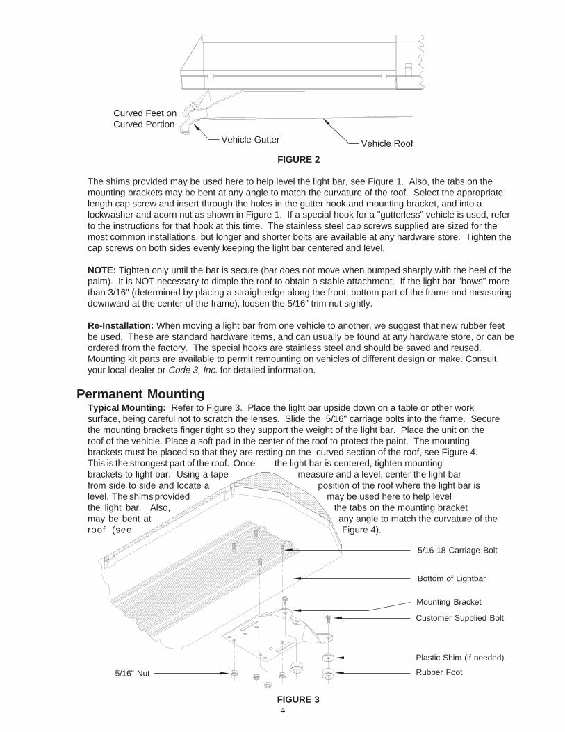
FIGURE 2
Vehicle RoofVehicle Gutter
Curved Feet onCurved Portion
The shims provided may be used here to help level the light bar, see Figure 1. Also, the tabs on themounting brackets may be bent at any angle to match the curvature of the roof. Select the appropriatelength cap screw and insert through the holes in the gutter hook and mounting bracket, and into alockwasher and acorn nut as shown in Figure 1. If a special hook for a "gutterless" vehicle is used, referto the instructions for that hook at this time. The stainless steel cap screws supplied are sized for themost common installations, but longer and shorter bolts are available at any hardware store. Tighten thecap screws on both sides evenly keeping the light bar centered and level.
NOTE: Tighten only until the bar is secure (bar does not move when bumped sharply with the heel of thepalm). It is NOT necessary to dimple the roof to obtain a stable attachment. If the light bar "bows" morethan 3/16" (determined by placing a straightedge along the front, bottom part of the frame and measuringdownward at the center of the frame), loosen the 5/16" trim nut sightly.
Re-Installation: When moving a light bar from one vehicle to another, we suggest that new rubber feetbe used. These are standard hardware items, and can usually be found at any hardware store, or can beordered from the factory. The special hooks are stainless steel and should be saved and reused.Mounting kit parts are available to permit remounting on vehicles of different design or make. Consultyour local dealer or Code 3, Inc. for detailed information.
Permanent MountingTypical Mounting: Refer to Figure 3. Place the light bar upside down on a table or other worksurface, being careful not to scratch the lenses. Slide the 5/16" carriage bolts into the frame. Securethe mounting brackets finger tight so they support the weight of the light bar. Place the unit on theroof of the vehicle. Place a soft pad in the center of the roof to protect the paint. The mountingbrackets must be placed so that they are resting on the curved section of the roof, see Figure 4.This is the strongest part of the roof. Once the light bar is centered, tighten mountingbrackets to light bar. Using a tape measure and a level, center the light barfrom side to side and locate a position of the roof where the light bar islevel. The shims provided may be used here to help levelthe light bar. Also, the tabs on the mounting bracketmay be bent at any angle to match the curvature of theroof (see Figure 4).
Mounting Bracket
5/16-18 Carriage Bolt
Customer Supplied Bolt
Plastic Shim (if needed)
Rubber Foot5/16" Nut
FIGURE 3
Bottom of Lightbar

5
FIGURE 4
Once the light bar is level and centered, mark the holes through the mounting tabs and remove thelight bar from the vehicle. Make sure that the drill will not damage anything when penetrating the roof.Drill the mounting holes and remove any burrs. Attachment can be made using 1/4" cap screws,toggle bolts, or other fasteners as may be convenient. Use sealant as necessary to prevent waterleakage into the vehicle.
Wiring InstructionsLarger wires and tight connections will provide longer service life for components. Forhigh current wires it is highly recommended that terminal blocks or soldered connectionsbe used with shrink tubing to protect the connections. Do not use insulation displace-ment connectors (e.g. 3M® Scotchlock type connectors). Route wiring using grommetsand sealant when passing through compartment walls. Minimize the number of splicesto reduce voltage drop. High ambient temperatures (e.g. underhood) will significantlyreduce the current carrying capacity of wires, fuses, and circuit breakers. Use "SXL"type wire in engine compartment. All wiring should conform to the minimum wire sizeand other recommendations of the manufacturer and be protected from moving parts andhot surfaces. Looms, grommets, cable ties, and similar installation hardware should beused to anchor and protect all wiring. Fuses or circuit breakers should be located asclose to the power takeoff points as possible and properly sized to protect the wiring anddevices. Particular attention should be paid to the location and method of makingelectrical connections and splices to protect these points from corrosion and loss ofconductivity. Ground terminations should only be made to substantial chassis compo-nents, preferably directly to the vehicle battery. The user should install a fuse sized toapproximately 125% of the maximum Amp capacity in the supply line to protect againstshort circuits. For example, a 30 Amp fuse should carry a maximum of 24 Amps. DONOT USE 1/4" DIAMETER GLASS FUSES AS THEY ARE NOT SUITABLE FORCONTINUOUS DUTY IN SIZES ABOVE 15 AMPS. Circuit breakers are very sensitiveto high temperatures and will "false trip" when mounted in hot environments or operatedclose to their capacity.
WARNING!
!
Before attempting to connect wiring refer to wire tag attached to the lightbar's main cable. Each wire inthe cable controls a separate lightbar function as described in the wire tag.
The only significant difference between the Excalibur with optional ArrowStik® and a conventionalExcalibur®, is the additional, thinner cable exiting the bottom of the lightbar. The larger cable is thelightbar power cable. Route the wiring cable into the engine or passenger compartment, taking care touse grommets and to apply sealant around openings to keep water out. It is advisable to leave an extraloop of cable when installing the light bar to allow for future changes or reinstallations. Connect the blacklead to a solid frame ground (earth), preferably, the (-) or ground (earth) side of the battery and bring theother wires to the control head or switches. Connect the wires to the control head or switch (as directedby the wiring instructions on the cable). Run a power wire from the control head to the (+) or positiveside of the battery, the alternator, or to the stud on the battery side of the starter solenoid, #8 AWGminimum.
Curved Roof Flat RoofPlace Feet onCurved Portion
6
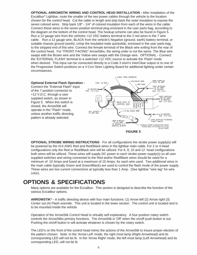
Optional External Flash Operation -Connect the "External Flash" inputof the 7 position connector to+12 V.D.C. through a usersupplied switch, as shown inFigure 5. When this switch isclosed, the ArrowStik willoperate in the "Flash" mode,unless another traffic directingpattern is already selected.
FIGURE 5
FEMALE CRIMP CONNECTOR FROMPARTS BAG, ATTACHED TO 12 GA
BLACK WIRE
OPTIONAL ARROWSTIK WIRING AND CONTROL HEAD INSTALLATION - After installation of theExcalibur® Lightbar, route the smaller of the two power cables through the vehicle to the locationchosen for the control head. Cut the cable to length and strip back the outer insulation to expose theseven colored wires. Strip back 1/8" - 1/4" of colored insulation from each of the wires in the cable.Connect these wires to the seven position terminal plug enclosed in the user parts bag, according tothe diagram on the bottom of the control head. The hookup scheme can also be found in Figure 5.Run a 12 gauge wire from the vehicles +12 VDC battery terminal to the 2 red wires in the 7 wirecable. Run a 12 gauge wire, BLACK from the vehicle's Negative (ground, earth) battery terminal, orsuitable chassis ground (earth), crimp the insulated male quickslide, enclosed in the user parts bag,to the stripped end of this wire. Connect the female terminal of the Black wire exiting from the rear ofthe control head. For "FRONT FACING" ArrowStiks, the wiring order is not the same. The Blue wireswaps with the Brown wire and the Yellow wire swaps with the Orange wire. OPTIONAL - Connectthe 'EXTERNAL FLASH' terminal to a switched +12 VDC source to activate the 'Flash' modewhen desired. This input can be connected directly to a Code 3 siren's InterClear output or to one ofthe Progressive Switch positions on a V-Con Siren Lighting Board for additional lighting under certaincircumstances.
OPTIONAL STROBE WIRING INSTRUCTIONS - For all configurations the strobe power supply(s) willbe powered by the #14 AWG Red and Red/Black wires in the lightbar main cable. For 2 or 4 headconfigurations only the Red or Red/Black wire will be utilized. For 6, 8, 10 and 12 head configurationsboth wires will be utilized. These wires will supply DC power to each strobe power supply(s) so all usersupplied switches and wiring connected to the Red and/or Red/Black wires should be rated for aminimum of 10 Amps and fused at a maximum of 15 Amps, for each wire used. Two additional wires inthe main cable (typically Green and Green/Black) are used to control the flash mode of the power supply.These wires are low current connections at typically less than 1 Amp. (See lightbar "wire tag" for wirecolor).
OPTIONS & SPECIFICATIONSMany options are available for the Excalibur. This section is designed to describe the function of thevarious Excalibur options.
ARROWSTIK® - A traffic directing device with four main functions: (1) Arrow left (2) Arrow right (3)Center out (4) Flash override. This unit is located in the lower section. The control unit is located and isto be mounted inside the vehicle.
Operation of the ArrowStik Control Head is virtually self explanatory. A four position rotary switchcontrols the ArrowStiks primary functions. The ArrowStik is 'Off' when the on/off push-button is out.Pushing the on/off button in will activate whatever is chosen by the rotary switch.
The LED's on the front of the control head mimic the actions of the ArrowStik to insure proper election ofthe pattern chosen. Note: In the 'Arrow Left' mode, the right most lamp (Right Arrowhead) and itscorresponding LED will not be lit. In the 'Arrow Right' mode, the left most lamp (Left Arrowhead) and itscorresponding LED, will not be lit.
7
The following are optional features that may or may not be included in your control head depending uponwhich model you purchased.
"Fast Speed" Mode: Fast speed and Dim Modes are combined. Pushing the button marked "Fast" willcause each of the 4 patterns of the ArrowStik to operate at a faster rate, with the same amount of lightintensity."Dim" Mode: Dim and Fast speed Modes are combined. Pushing the button marked "Dim" will causeeach of the 4 patterns of the ArrowStik to operate at a lower intensity level. This is for use at night when100% intensity is too much, or daytime when current draw needs to be reduced."Aux" Mode: Pushing the button marked "Aux" will activate the control head internal relay. This willswitch +12 V.D.C. to the terminal marked "Aux Output" in Figure 1. The red LED on the front panel willalso come on. This indicates that the auxiliary switch is on. This output is limited to 12 Amps.
Control Head Options: S99114 Code 3 BasicS99119 Code 3 Deluxe
STROBE LIGHTING CONNECTIONS
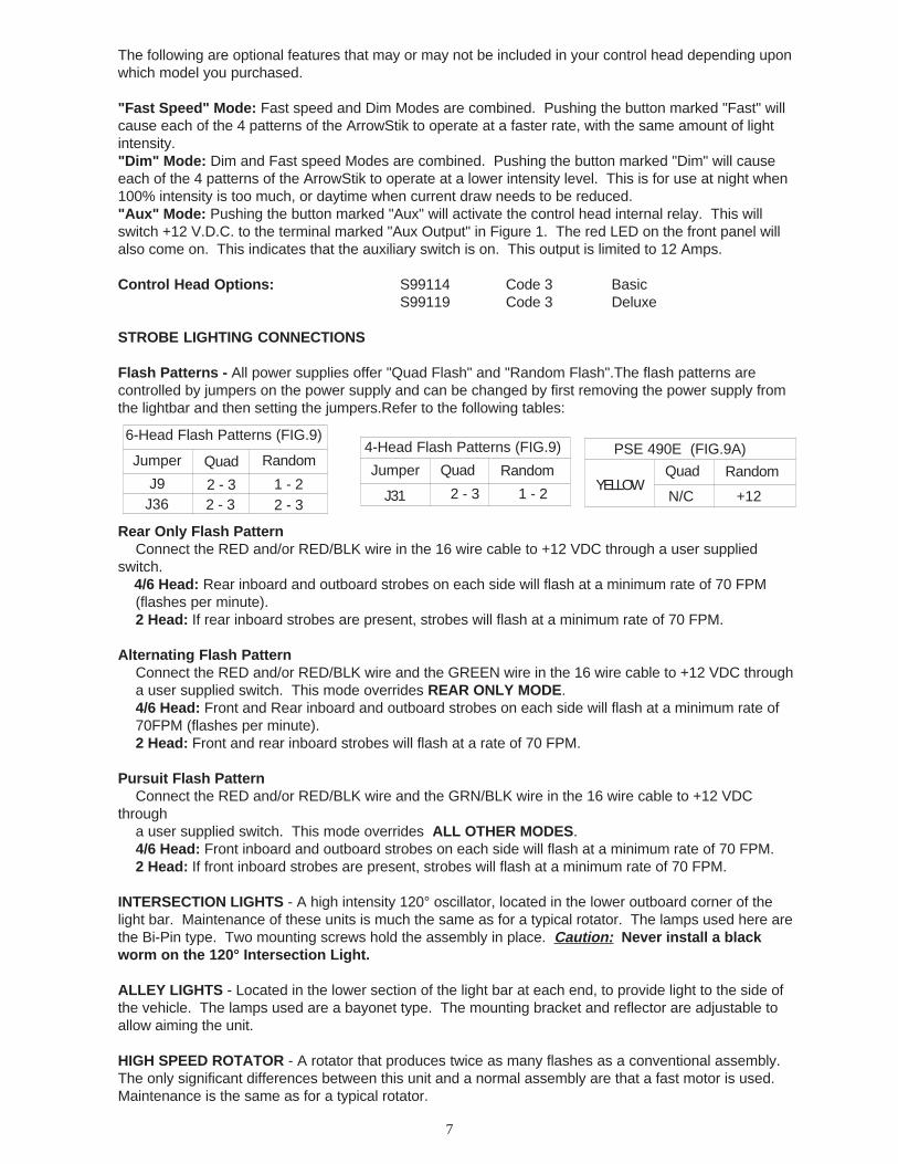
Flash Patterns - All power supplies offer "Quad Flash" and "Random Flash".The flash patterns arecontrolled by jumpers on the power supply and can be changed by first removing the power supply fromthe lightbar and then setting the jumpers.Refer to the following tables:
Rear Only Flash PatternConnect the RED and/or RED/BLK wire in the 16 wire cable to +12 VDC through a user supplied
switch. 4/6 Head: Rear inboard and outboard strobes on each side will flash at a minimum rate of 70 FPM
(flashes per minute).2 Head: If rear inboard strobes are present, strobes will flash at a minimum rate of 70 FPM.
Alternating Flash PatternConnect the RED and/or RED/BLK wire and the GREEN wire in the 16 wire cable to +12 VDC througha user supplied switch. This mode overrides REAR ONLY MODE.4/6 Head: Front and Rear inboard and outboard strobes on each side will flash at a minimum rate of70FPM (flashes per minute).2 Head: Front and rear inboard strobes will flash at a rate of 70 FPM.
Pursuit Flash PatternConnect the RED and/or RED/BLK wire and the GRN/BLK wire in the 16 wire cable to +12 VDC
througha user supplied switch. This mode overrides ALL OTHER MODES.4/6 Head: Front inboard and outboard strobes on each side will flash at a minimum rate of 70 FPM.2 Head: If front inboard strobes are present, strobes will flash at a minimum rate of 70 FPM.
INTERSECTION LIGHTS - A high intensity 120° oscillator, located in the lower outboard corner of thelight bar. Maintenance of these units is much the same as for a typical rotator. The lamps used here arethe Bi-Pin type. Two mounting screws hold the assembly in place. Caution: Never install a blackworm on the 120° Intersection Light.
ALLEY LIGHTS - Located in the lower section of the light bar at each end, to provide light to the side ofthe vehicle. The lamps used are a bayonet type. The mounting bracket and reflector are adjustable toallow aiming the unit.
HIGH SPEED ROTATOR - A rotator that produces twice as many flashes as a conventional assembly.The only significant differences between this unit and a normal assembly are that a fast motor is used.Maintenance is the same as for a typical rotator.
6-Head Flash Patterns (FIG.9)
Jumper Quad RandomJumper Quad Random
J9J36 J31 2 - 3 1 - 2
2 - 32 - 3
2 - 31 - 2
PSE 490E (FIG.9A)
YELLOWQuad Random
N/C +12
4-Head Flash Patterns (FIG.9)

8
WARNING!
Lamps are extremely hot! Allow to cool completely before attempting toremove. Gloves and eye protection should be worn when handling halogenlamps as they are pressurized and accidental breakage can result in flyingglass.
!
STATIONARY LAMPS/TAKEDOWN LIGHTS - A stationary reflector assembly used for ArrowStikflashing, takedown, and/or work light applications. These are located in the lower section of the light bar.Lamps in these units are bayonet type and the units are mounted with two screws.
STOP/TURN/TAIL LIGHTS - Located in the upper section of the light bar facing rear, one on the driverside, one on the passenger side, these lights provide stop, turn and tail signals to following traffic whenconnected to the vehicle lighting system. Lamps used are an 1157 bayonet type.
D.O.T. LIGHTS - A set of three marker lights as required by the Department of Transportation for truckapplication. Lamps are wedge base '194' type.
OSCILASERTM - This is a highly effective warning light that features a constant 50 watt halogen signalthat covers every area within it's field of illumination at least once per second. It has an up and down aswell as a side to side signal. Maintenance for these units is much the same as a typical rotator. Thelamps used are bayonet type. This unit is located in the upper center section and/or in the centerposition in the outboard sections of the light bar.
MaintenanceLens Cleaning
Use plain water and a soft cloth, or Code 3 lens polish and a very soft paper towel or facial tissue.Because plastic scratches easily, cleaning is recommended only when necessary (about every sixmonths). Do not subject the lenses to car washes that use brushes, as these will scratch the lenses.
Lens Removal
First, disengage the lens clips(4 per lens) as shown inFigure 6. Finally, insert ascrewdriver into the insideedge or corner of the lens, andtwist the screwdriver to lift thelens.
Changing Rotating Reflector Lamps
Figure 6
Remove the lens as outlined above. Next, inspect the lamp and compare to Figure 7 to determine lamptype. It may be necessary to remove any rotating or cylindrical filters to make access easier. Note:Make sure lamp is cool before attempting to change it. Also, when installing a new lamp, be sure not totouch the glass with fingers. If contact is made, clean the glass with a soft cloth after inspection.H-1: First grasp lamp at base and turn until retaining clip tab is accessible. Using a blade screwdriver,remove retaining clip and pull lamp straight up. Replace with new lamp. Insure that the power lead andretaining clip is fully seated.
Twist toLift Lens
Pry Up toRemoveLens Clip

9
Figure 7
S-795 (Bayonet Style): Push down andturn to remove lamp. Install a new lampthe same way.Note: If attempting to clean the reflector,use only a mild glass cleaner and a verysoft cloth. Do not attempt to use any waxtype products as these will burn onto thereflector.
Changing Lower Unit Lamp and/or Filter
Refer to Figure 10. Remove the reflectorassembly by removing the appropriatefasteners, then remove the snap-on filter ifnecessary. In most cases, these lamps will be abayonet style, so simply push in and turn counterclockwise toremove.
Replacement for Upper and Lower Level Components
See exploded view "Parts Section" for fastener removal, component location, and assemblyconfiguration. Caution, extreme care must be taken when installing components to preventpinching wire connections and to avoid interference with moving assemblies.
!WARNING!
High voltages and/or temperatures are present inside the unit. Disconnect from powerand wait 10 minutes prior to servicing or troubleshooting. Use hand and eye protectionwhen changing halogen lamps or flashtubes.
Strobe Filter Replacement
Refer to figure 8. The filter can be removed by unsnapping it from the light head and by removing the mirror ifpresent for clearance. Prying the filter from the front may damage the glass strobe tube or reflector.To replace the filter, reverse the above procedure. The filter should be fully engaged on the light head assem-bly. Care should be taken to not damage the strobe tube or to scratch the reflective surface of the reflectorwhen replacing the filter.
Strobe Light Head Replacement
Refer to figure 8. Disconnect the light head assembly from the strobe power supply and remove the filter if any.Unfasten the screws attaching the light head mounting bracket to the light bar chassis and remove the lighthead from the light bar. On a bench or other work suitable work surface unfasten the screws attaching thestrobe light head assembly from the light head mounting bracket. Install the new strobe light head assembly tothe light head mounting bracket and reinstall the light head back onto the light bar chassis. Reconnect the lighthead wiring to the strobe power supply and reattach the filter. It is important to reroute and secure the wiring asclose as possible to its original position.
Caution, verify that no wires are interfering with the operation of the fan located at the end of thepower supply.

10
Electronics Module Removal
In the event that the power supply or a strobe lighthead assembly must be returned to the factory forservice, mark each wire with a tag to identify each function and note the proper location beforedisconnecting the wiring. Figure 9 can be used to mark the locations of the individual connections aswell.
Refer to Figure 9 for power supply removal. Remove the four (4) screws holding the power supply.Disconnect the wire leads, and move the power supply to the side. Remove the 2 screws holding thecapacitor assembly and lift the strobe power supply/capacitor assembly from the lightbar as a unit. Toreinstall the power supply reverse the above steps.Caution: Verify that wires are not pinched or damaged when reinstalling power supply.
Strobe LightheadAssembly
Filter(if supplied)
FIGURE 8

11
FIGURE 94-Head Power Supply
6-Head Power Supply
+12VDC (Red) +12VDC
(Red)
Ground Wire (Blk)
Ground Wire (Blk)
Control WireHarness(Yel/Blk,Brn/Blk)
Control WireHarness (Yel/Blk,Brn/Blk)
Passenger's Side Front(Org,Blk,Blk/Wht)Driver's Side Front(Brn,Blk,Blk/Wht)Passenger's Side Rear(Grn,Blk,Blk/Wht)Driver's Side Rear(Yel,Blk,Blk/Wht)
Rear Aux. Output(Red,Blk,Blk/Wht)Rear Output(Grn,Blk,Blk/Wht)Rear Output(Yel,Blk,Blk/Wht)
Front Output(Brn,Blk,Blk/Wht)Front Output(Org,Blk,Blk/Wht)Front Aux. Output(Wht,Blk,Blk/Wht)
1
2
3
4
5 N/C
REAR
+12v(RED)GND(BLK)
N/C(GREY)
FRONT(GRN)REAR(BLUE)
RANDOMFLASH(YEL)
PSE 490E
FIGURE 9A
FRONT

12
FIGURE 10
FIGURE 11
6.00
3.054.00
10.95
.4003.30
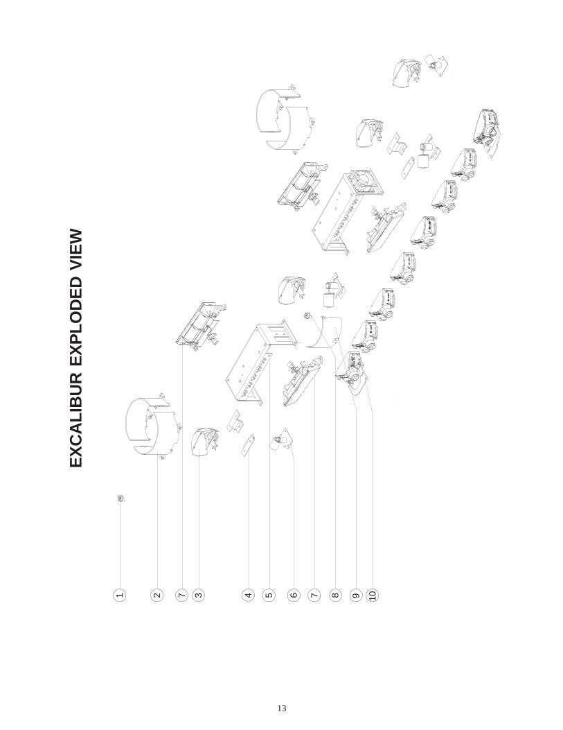
13
64 5 9 103721 8
EX
CA
LIB
UR
EX
PL
OD
ED
VIE
W
7

14
11121314 15 16
18 17
Not
e: A
ll sc
rew
s ar
e pa
rt n
o. 1
215
unle
ss o
ther
wis
e in
dica
ted
FIG
UR
E 1
2

15
Parts List(Reference numbers identify items shown in Figures on previous pages)Ref No. Description Part No.
8 #8 x .250" Sheet Metal Screw T05029#8 x .270" Sheet Metal Screw T01215
1 #8 x .375" Sheet Metal Screw T002435/16" Cable Clamp T003461/2" Cable Clamp T009033/8" Cable Clamp T00938
H-1 Lamp Retaining Clip T00928H-1 55W 12V Halogen Lamp T01543S795 50W 12V Halogen Lamp T01540S795 27W 12V Halogen Lamp T05077S795 20W 12V Halogen Lamp T050761156 28W 12V Incandescent Lamp T01538
3 Rotating Reflector Assembly S95977
6 Rotator Motor Assy--(Does not include Reflector Assy)Rotator Motor Assy 55W H-1 Std Speed S95978Rotator Motor Assy 55W H-1 Fast Speed S95979Rotator Motor Assy 50W Bayonet Std Speed S95980Rotator Motor Assy 50W Bayonet Fast Speed S95981Rotator Motor Assy 24V S95982
9 Rotating FilterGreen S95988Red S95989Blue S95990Amber S95991
2+4 Excalibur Cyl. Filter Assy (Front and Rear)Green S50870Red S50872Blue S50873Amber S50874
Lens Clip T01777Excalibur Top Outboard Lens
Clear T02101Red T02102Blue T02103Amber T02104
Excalibur Top Center LensClear T02131Red T02132Blue T02133Amber T02134
16 Excalibur Bottom Outboard Lens - Clear T0236117 Excalibur Bottom Center Lens - Clear T02371
Excalibur Full Diamond Mirror S50836Excalibur 2-Step Cascade Mirror Dr. Front Flash S50791Excalibur 2-Step Cascade Mirror Pass Front Flash S50792Excalibur Flat Mirror Dr. Front or Pass Rear Flash S50787Excalibur Flat Mirror Dr. Rear or Pass Front Flash S50788Excalibur 104° V-Mirror S50793

16
13 Excalibur 20W Halogen Stationary Module S50849Excalibur 27W Halogen Stationary Module S50850Excalibur 28W Incandescent Stationary Module S50851
10 Excalibur 28W Incandescent Arrowstik Module S5084818 Excalibur 20W Halogen Alley Light Driver S5085514 Excalibur 20W Halogen Alley Light Pass S50856
Excalibur 27W Halogen Alley Light Driver S50863Excalibur 27W Halogen Alley Light Pass S50864
15 Halogen Lower Light Head FilterGreen T05170Clear T05171Red T05179Blue T05173Amber T05174
Excalibur External D.O.T. Strip Assembly S50838Excalibur Stop/Turn/Tail Light W/Adapter Plate S50837OsciLaser Module S50343Upper Level 50W Halogen Stationary Module S50839
5 Strobe 2-Head Power Supply S80318Strobe 4-Head Power Supply S80313Strobe 6-Head Power Supply S80341
7 Strobe Upper Light Head Assembly – End Signal Position T09424Strobe Up Lt Hd Assy – End Sig Pos Mirror – DS Frt/PS Rr T09409Strobe Up Lt Hd Assy – End Sig Pos Mirror – PS Frt/DS Rr T09406Strobe Upper Light Head Assy – End Signal Pos Filter
Red T09442Blue T09443Amber T09444
Strobe Upper Light Head Assembly – Directional Position T09425Strobe Upper Light Head Assy – Directional Pos Filter
Red T09432Blue T09433Amber T09434
11 Strobe Lower Corner Light Head Assembly S5089212 Strobe Lower Front/Rear Light Head Assembly S50888
Strobe Lower Light Head Tube Assembly T03893Strobe Lower Light Head Filter
Green T03910Red T03912Blue T03913Amber T03914
LEDX 2100 22.5" Upper Beacon Lens (Clear) T07971LEDX 2100 22.5" Lower Beacon Lens (Clear) T07961LEDX 2100 22.5" Lower Beacon Lens (Amber) T07964 22.5" Upper Excalibur Lens (Clear) T0795122.5" Upper Excalibur Lens (Red) T0795222.5" Upper Excalibur Lens (Blue) T0795322.5" Upper Excalibur Lens (Amber) T07954
22.5" Beacon Lens Part Numbers

17
STROBE OPTIONTROUBLESHOOTING GUIDE
PROBLEM
Light heads donot fire.
Only frontstrobes flash.
CAUSE
a.Harness that connects powersupply to strobe head has looseconnections or damagedharness.
b. Faulty strobe Lighthead.c. High voltage shorting to ground
(earth) through harness.
a. GRN/BLK control wire connectedto +12VDC overrides othermodes.
SOLUTION
a. Check all connections.Check harness by switching harness with functioningstrobe head.Replace harness.
b. Check with known good Lighthead.c. Isolate shorted harness by disconnecting one at a time.
Replace harness.
a. See "Strobe Lighting Connections" section.Reconnect switching.
TroubleshootingAll Excalibur® Strobe Lightbars are thoroughly tested prior to shipment. However, should you encounter aproblem during installation or during the life of the product, follow the guide below for information on repair andtroubleshooting. Additional information may be obtained from the factory technical help lineat 314-426-2700 ext. 2132.
NO STROBE LIGHTS IN THE LIGHTBAR OPERATE - Check the following: 1) +12 VDC source connectionfor the control switch box and any in line fuse 2) Connection of the RED and RED/BLK wire at the controlswitch box 3) Check the 15 Amp ATO fuse on each power supply. If the fuse is blown, replace it with another15 Amp fuse and test the lightbar. If the fuse continues to blow, return the power supply only, NOT the entirelightbar, to the factory for service. For instructions on power supply removal see the " Electronics ModuleRemoval " section of this manual.
Do not replace the fuse with one of a higher rating. This will damage the power supplyand void all warranties.
WARNING!!
ONE STROBE LIGHT MODULE DOES NOT OPERATE - Check the defective strobe light module byswitching it with a module that is known to be working.

18
PROBLEM
ArrowStik does notfunction whenturned on
Lamp does notcome on when itshould.
Right most lampdoes not come onin Arrow Left modeor left most lampdoes not come onin Arrow Rightmode.
ArrowStik runsopposite patternthan selected.
Lamp looks dim.
CAUSE
a. Plug in rear of control box isloose or disconnected.
b. Poor ground connectiona. Power from battery has been
disconnected or the controlbox has been damaged.
a. Lamp has burned out.b. Bad wiring connection.
a. Control box has beendamaged.
a. Normal operation
a. Defective Wiring.
b. Control box has beendamaged.
a. Defective lamp.b. Low voltage.c. Poor groundd. Product is in "Dim" mode.
SOLUTION
a. Reconnect plug.
b. Reconnect ground.a. Check connections at the battery
and plug. If connections are goodand voltage is at least 10 volts, thecontrol box has been damaged.Repair or return to Code 3.
a. Replace lamp.b. Repair connection.
a. Repair or return to Code 3.
a. None
a. Check that the cable exit is on thedriver's side
b. Repair or return to Code 3.a. Repair or return to Code 3.
a. Replace lamp.b. Check connections or battery.c. Check ground and wire gauge.d. Select appropriate mode.
QUESTION
Are LED's func-tioning properly?
Yes
No
Are LED's func-tioning properly?
Yes
No
Follow the guide below for information on repair and trouble shooting for the arrowstik option.
ARROWSTIK® OPTIONTROUBLESHOOTING GUIDE
NOTES:

19
NOTES

20
Code 3 is a registered trademark of Code 3, Inc. a subsidiary of Public Safety Equipment, Inc.
Revision 9, 01/05 - Instruction Book Part No. T05075©2005 Code 3, Inc. Printed in USA
WARRANTYCode 3, Inc. emergency devices are tested and found to be operational at the time of
manufacture. Provided they are installed and operated in accordance with manufacturer'srecommendations, Code 3, Inc. guarantees all parts and components except the lamps to a periodof 1 year (unless otherwise expressed) from the date of purchase or delivery, whichever is later.Units demonstrated to be defective within the warranty period will be repaired or replaced at thefactory service center at no cost.
Use of lamp or other electrical load of a wattage higher than installed or recommended by thefactory, or use of inappropriate or inadequate wiring or circuit protection causes this warranty tobecome void. Failure or destruction of the product resulting from abuse or unusual use and/oraccidents is not covered by this warranty. Code 3, Inc. shall in no way be liable for other damagesincluding consequential, indirect or special damages whether loss is due to negligence or breachof warranty.
CODE 3, INC. MAKES NO OTHER EXPRESS OR IMPLIED WARRANTY INCLUDING,WITHOUT LIMITATION, WARRANTIES OF FITNESS OR MERCHANTABILITY, WITHRESPECT TO THIS PRODUCT.
PRODUCT RETURNSIf a product must be returned for repair or replacement*, please contact our factory to
obtain a Return Goods Authorization Number (RGA number) before you ship the product toCode 3, Inc. Write the RGA number clearly on the package near the mailing label. Be sure youuse sufficient packing materials to avoid damage to the product being returned while in transit.
*Code 3, Inc. reserves the right to repair or replace at its discretion. Code 3, Inc. assumes no responsibility or liability for expenses incurred forthe removal or reinstallation of products requiring service or repair.
Code 3, Inc.10986 N. Warson Road
St. Louis, Missouri 63114-2029—USAPh. (314) 426-2700 Fax (314) 426-1337
www.code3pse.com