ewa ewa2017 2017 electrical wiring accessories
TRANSCRIPT

1
EWA2017
Electrical Wiring
AccessoriesEW
A 2
017

Mission Statement
To become the preferred supplier of electrical, lighting and safety solutions for mobile plant and equipment in the
mining and services industry.
We will continue to improve and expand our range of products that meet and exceed OEM standards,
maintaining the latest technology and innovation available backed by technical support and supply.

Conduit & Conduit FittingsPolyflex® PA6 7
Polyflex® PPmod 8
PP Split 10
Conduit Tools & Accessories 11
Military Plug Adaptors 15
SEM-FAST Adaptors 16
Threadconnect Adaptors 18
Threadconnect Fittings 20
Threadconnect Reducers 22
Hinged ‘T’ & ‘Y’ Fittings 23
Fitting AccessoriesGrommets Bushes & Glands 30
Cable Ties 32
Clips & Clamps 34
Electrical Tape 38
Mémocab Marking System 39
Terminal Insulators/Boots 40
SleevingPVC Tubing 44
Flexible Braiding 45
Flexible Braiding – Nylon 46
High Temp Sleeving 47
Spiral Wrap 48
Standard Wall Heatshrink 50
Adhesive-lined Heatshrink 53
EnclosuresABS/Thermoplastic 58
PVC 62
Die-cast 63
Pendant Control 64
Fuel Junction 66
Engraved Panels 67
Circuit ProtectionCircuit Breakers – General 70
Circuit Breakers – Heavy Duty 72
Circuit Breakers – Marine 74
Circuit Breakers – Toggle 75
Circuit Breakers – Blade 76
Fuses 78
Fuse Holders 82
Blade Fuse Tap 85
Power Distribution Modules 86
Mini Electrical Centres 88
Circuit Protection cont.
Modular MFL Fuse Holder 90
Bolt-in Fuses 92
Bolt-in Fuse Holders 94
Modular AMI Fuse Holder 97
Plug-in Diodes 98
Diodes 99
CableThin Wall Cable 102
Single Cable 107
Battery Cable 110
Tinned Cable 112
Sheathed Cable – Single/Multi Core 114
Twin Core Figure 8 Cable 115
Speaker Cable 115
Coaxial RG58 Cable 115
Multi Core Cable – Flexible Control 116
CAN Data Cable 116
Special Cable 116
ToolsCrimping Tools 120
Contact Removal Tools 124
Workshop Tools 126
ElectronicsVoltage Converters 132
RCD/GPO Inverters 135
Pure Sine Wave Inverters 136
Combi Inverter/Chargers 138
AC to DC Battery Chargers 140
DC to DC Battery Chargers 141
Power Supplies 142
Battery Separators 143
Battery Monitor 144
Hour Meter 145
RustStop® 146
Brake Controllers 147
Idle Timers 148
Flasher Units 150
BulbsBulbs 154
Index160

PA6 PPmod (High Temp) PP (Standard)PA6 (Nylon) is ideal for applications that require a conduit with high impact and abrasion protection with outstanding chemical resistance.
PA6 (Nylon) conforms to FMVSS302, is flame retardant, halogen free and maintains excellent flexibility in temperature extremes of -40°C to 120°C.
PA6 (Nylon) conduit is supplied non-split making it ideal for mining and fuel haul applications when used with the extensive range of Schlemmer sealed fittings.
PPmod (High Temperature Polypropylene) makes for a flexible conduit with good impact and abrasion resistance and can withstand a broad range of chemicals.
PPmod has a working temperature range of -40°C to 135°C, is self extinguishing and conforms to FMVSS302.
PPmod (High Temperature Polypropylene) conduit is supplied non-split as well as in a 'Lockable' format making it ideal for use in engine bays, open environment applications or for application after a harness has been installed.
PP (Standard Polypropylene) is used in the manufacture of basic automotive conduit.
FMVSS302 compliant, a temperature range of -40°C to 105°C with basic impact, abrasion and chemical resistance. PP (Standard Polypropylene) is ideal for vehicle interior, chassis and body sections.
PP (Standard Polypropylene) conduit is only available in split configuration and is compatible with a wide range of Schlemmer Hinged Fittings and SEM-FAST adaptors.

Conduit & Conduit FittingsPolyflex® PA6 7
Polyflex® PPmod 8
PP Split 10
Conduit Tools & Accessories 11
Military Plug Adaptors 15
SEM-FAST Adaptors 16
Threadconnect Adaptors 18
Threadconnect Fittings 20
Threadconnect Reducers 22
Hinged ‘T’ & ‘Y’ Fittings 23

6
Conduit & Conduit Fittings
Identification
NW Size Cross ReferenceDue to varying sizing methods and manufacturer interpretations there are different sizing formats used for PA6, PP Split and PPmod Lockable conduit.
The table below provides a cross-reference for all conduit ranges within this catalogue to Schlemmer NW sizing, and to UK NC sizing.
NWSchlemmer Identification
PA6 Conduit
PPmod Lockable Conduit
PP Split Conduit
NCUK
Identification
Size Part Number Part Number NW V Part Number Size
NW4.5 1200068 — — — NC06
NW6 1200069 — — — NC07
NW7.5 1200070 — — LT7 NC08
NW8.5 1200089 — — — NC10
NW10 1200100 1940008 NW8.5 V LT10 NC12
NW13 1200135 1940011 NW11 V LT13 NC16
NW14 — 1940013 NW13 V — —
NW17 1200178 1940015 NW15 V LT16 NC20
NW22 1200224 1940019 NW19 V LT20 NC25
NW26 — 1940026 NW26 V — NC30
NW29 1200291 — — LT30 NC32
NW37 1200372 — — LT36 NC40
NW50 1200500 — — — NC50
Please note that due to many different qualities of split conduit available on the market only IONNIC supplied PP & PPmod Split Conduit is confirmed to match the above NW sizing.
Conduit Sealed Fittings Hinged Fittings
Marked on all rolls of PA6 & PPmod conduit, as well as all Hinged Fittings and SEM-FAST Fittings is an 'NW' number.

7
Conduit & Conduit Fittings
• Highly durable & flexible.
• Self-extinguishing, flame retardant & halogen free.
• High chemical, oil & solvent resistance.
• Wide range of sizes.
Material : Polyamide 6 (PA6)Operating Temperature : Continuous -40 °C to 120°C
Short Term 150°CApprovals : TUV, NFR, L.C.O.E., UL, ADR & GGVSBurning Behaviour : FMVSS 302, <100mm/min
UL94 HBUV Resistance : DIN EN ISO 8580
Polyflex
® PA6
Polyflex® PA6 Corrugated Conduit (Nylon)Part No. NW – A NC – A B (mm) C (mm) Roll Length (m)
1200068/100 4.5 6 7.1 5.0 100
1200069/100 6.0 7 9.2 6.0 100
1200070/50 7.5 8 10.0 6.7 50
1200807/5000 7.5 8 10.0 6.7 5000
1200089/50 8.5 10 11.7 8.4 50
1200808/3300 8.5 10 11.7 8.4 3300
1200100/50 10.0 12 13.0 9.9 50
1200810/3000 10.0 12 13.0 9.9 3000
1200135/50 13.0 16 15.8 12.7 50
1200813/2000 13.0 16 15.8 12.7 2000
1200178/50 17.0 20 21.2 16.6 50
1200817/1100 17.0 20 21.2 16.6 1100
1200224/50 22.0 25 25.4 21.3 50
1200822/700 22.0 25 25.4 21.3 700
1200291/25 29.0 32 34.5 29.0 25
1200829/450 29.0 32 34.5 29.0 450
1200372/25 37.0 40 42.4 36.0 25
1200500/25 50.0 50 54.0 47.0 25
BCA

8
Conduit & Conduit Fittings
Pol
yflex
® P
Pm
od
• Available in locking and split styles.
• Incorporated locking mechanism for security and usability.
• Can be reopened after being locked closed.
• Can be closed by hand or for high volumes, closing tool available.
• Self-extinguishing & flame retardant.
• UV resistant & acid proof.
• Ideal for extreme temperature application.
Material : High Temperature PolypropyleneOperating Temperature : Continuous -40 °C to 135°C
Short Term 500 hrs @150°CBurning Behaviour : FMVSS 302
Self-extinguishing Type B & burning rate 0 (DIN7500)UV Resistance : DIN EN ISO 8580
Polyflex® PPmod Corrugated Conduit – SplitPart No. NW – A B (mm) C (mm) Roll Length (m)
1927304/100 4.5 7.1 5.0 100
1927306/100 6 9.2 6.0 100
1927308/50 8.5 12.9 8.5 50
1927311/50 11 15.7 11.1 50
B
A
C

9
Conduit & Conduit Fittings
Lockable Conduit
Lockable Conduit Closing Tool
Polyflex® PPmod Corrugated Conduit – LockablePart No. NW V – A NW – A B (mm) C (mm) Roll Length (m)
1940008/50 8.5 10 12.8 8.6 50
1940011/50 11.0 13 15.7 11.2 50
1940013/50 13.0 14 18.3 12.2 50
1940015/50 15.0 17 21.3 14.9 50
1940019/50 19.0 22 25.6 19.0 50
1940026/25 26.0 26 31.5 24.6 25
NW V size is marked on PPmod Lockable Conduit.
B
A
C
Pinch one end of PPmod Lockable conduit closed and squeeze on closing tool.
While holding one end pull the locking tool down the length of conduit.
Closing Tool
See page 14 for more details.
Polyflex PPmod Lockable conduit has been specifically developed to incorporate the convenience of a split conduit combined with the benefits and security of an non-split conduit.
The locking mechanism provides a secure seal which can be simply reopened after locking to allow access to the harness without damaging the conduit in the process.
Unlocked
Can be closed by hand or for high volumes, closing tools are available, see page 14.
Locked

10
Conduit & Conduit Fittings
• Quick & easy cable insertion.
• Wide range of sizes & lengths available.
• Compatible with a wide selection of the Schlemmer Hinged and SEM-FAST fittings.
Material : PolypropyleneOperating Temperature : Continuous -20 °C to 90°C
Short Term 120°C
PP Corrugated Conduit – SplitPart No. NW – A B (mm) C (mm) Roll Length (m)
LT7/50 7.5 10.4 7.0 50
LT7/400 7.5 10.4 7.0 400
LT10/30 10 12.8 9.7 30
LT10/250 10 12.8 9.7 250
LT13/30 13 15.7 12.6 30
LT13/150 13 15.7 12.6 150
LT16/30 17 20.9 16.3 30
LT16/100 17 20.9 16.3 100
LT20/30 22 25.2 21.1 30
LT20/100 22 25.2 21.1 100
LT25/10 23 30.0 25.0 10
LT25/50 23 30.0 25.0 50
LT30/10 29 35.0 31.2 10
LT30/50 29 35.0 31.2 50
LT36/25 37 42.0 36.0 25
Only IONNIC supplied PP Split Conduit is confirmed to match NW sizing on the market.
Not a Schlemmer product.
PP S
plit
A
C
B

11
Conduit & Conduit Fittings
Conduit Support ClipsPart No. NW – A NC – A B (mm) C (mm) D (mm) Pack Qty Fig
9805940/10 4.5 6 10 12 10 10 1
9805941/10 7.5 8 13 15 13 10 1
9805941/100 7.5 8 13 15 13 100 1
9805939/10 8.5 10 16 18 13 10 2
9805942/10 10 12 16 18 13 10 1
9805943/10 13 16 19 21 13 10 1
9805944/10 17 20 24 26 15 10 1
9805945/10 22 25 29 30 16 10 1
Clips use corrugations to hold conduit in place to stop any lateral movement.
D
B
CA
D
B
CA
Fig 2Fig 1
SJ32
9001555
9805916/10
9805916/5
9805943/108211000/10
Conduit Tools &
Accessories
• End Caps/Sleeves suitable for single or multiple cables.
• Quick & easy means of conduit termination using End Caps.
• Securely fasten PP Split & PPmod conduit using Conduit Support Clips.
• Quick & secure ‘pop-in’ style Christmas Tree mounting clips.
• ‘P’ Clamps for offset mounting.
• Range of conduit tools available.
9805939/10 9805945/10

12
Conduit & Conduit Fittings
Conduit Mounting ClipsPart No. NW – A NC – A B (mm) C (mm) D (mm) Pack Qty
9805917/10 4.5 6 21 13 13 10
9805911/10 7.5 8 24 16 13 10
9805912/10 8.5 10 25 17 13 10
9805913/10 10 12 27 18 13 10
9805914/10 13 16 30 21 13 10
9805925/10 17 20 35 26 13 10
9805916/10 22 25 40 31 13 10
Clips use corrugations to hold conduit in place to stop any lateral movement.
10mm
8mm A
DC
B
MountingDimensions
Ø 6.5mm
9805917/10 9805914/10
8211019/108211094/10
B
C A
D E
‘P’ Clamps – Heavy DutyPart No. A (mm) B (mm) C (mm) D (mm) E (mm) Pack Qty
8211060/10 5.7 – 6.3 28 10 16 6.6 10
8211094/10 8.6 – 9.3 30 14 16 6.6 10
8211108/10 9.5 – 10.3 32 15 16 6.6 10
8211124/10 11.5 – 12.3 34 17 16 6.6 10
8211000/10 12.3 – 13.3 36 18 16 6.6 10
8211035/10 15.5 – 16.3 38 121 16 6.6 10
8211019/10 21.4 – 22.3 47 27 19 6.6 10
8211027/10 24.4 – 25.3 58 32 23 8.6 10

13
Conduit & Conduit Fittings
Conduit End CapsPart No. NW – A NC – A B (mm) C (mm) No. of Outlets Pack Qty
SJ03/5 8.5 – 10 10 – 12 20 15 3 5
SJ05/5 10 12 21 17 5 5
SJ06/5 13 16 24 19 6 5
Single cable outlets can be achieved by trimming the end from an individual gland.
A
BC
A
B
C
SJ03/5
Conduit End SleevesPart No. NW – A NC – A Outlet Ø – B (mm) C (mm) D (mm) Pack Qty
SJ12/5 10 12 4 – 8 29 18 5
SJ16/5 13 16 6 – 10 33 22 5
SJ20/5 17 20 9 – 15 33 27 5
SJ25/5 22 25 10 – 17 47 29 5
SJ32 29 32 12 – 20 48 35 1
SJ40 37 40 19 – 30 47 44 1
A B
D
C
A B
D
C
SJ12/5

14
Conduit & Conduit Fittings
Conduit ToolsPart No. Description Suitable Conduit Size (NW) Suits Fig
9001511 Single cable insertion tool 6 – 13 Lockable & Split 1
9001520 Universal cable insertion tool with offset flange 10 – 26 Lockable & Split 2
9001543 Universal cable insertion tool – small 8.5 – 12 Lockable & Split 3
9001550 Universal cable insertion tool – large 13 – 26 Lockable & Split 3
9001558 Closing tool for PPmod Lockable conduit – Black 8.5 V Lockable 4
9001561 Closing tool for PPmod Lockable conduit – Grey 11 V Lockable 4
9001552 Closing tool for PPmod Lockable conduit – Blue 13 V Lockable 4
9001567 Closing tool for PPmod Lockable conduit – Yellow 15 V Lockable 4
9001555 Closing tool for PPmod Lockable conduit – Green 19 V Lockable 4
9001564 Closing tool for PPmod Lockable conduit – Red 26 V Lockable 4
Fig 1 Fig 3Fig 2 Fig 4
Using Conduit Tools
Insert the point of the single cable insertion tool into end of conduit with cable as shown.
While holding end of conduit with cable, pull the insertion tool down the length of conduit.
Single Cable Insertion Tool
Pinch one end of PPmod Lockable conduit closed and squeeze on closing tool.
While holding one end pull the locking tool down the length of conduit.
Closing Tool
Insert tool wedge containing wires into conduit split.
Universal Cable Insertion Tool
Drag insertion tool down the length of conduit whilst holding cables.
Hold

15
Conduit & Conduit Fittings
Military P
lug Adaptors
Adaptor Body : PolycarbonateConical Seal : NeopreneCap Nut : Polyamide 6
Military Plug Adaptor KitsPart No. NW – A NC – A Thread Size – B C (mm) D (mm) Notes
SF02 10 12 7/8” -20 UNEF 36 31
SF06 10 12 1” -20 UNEF 39 35
SF03 17 20 1” -20 UNEF 36 35
SF01 17 20 M35 x 1.75 36 35 Suits Deutsch HDP Series with L015 mod.
SF04 17 20 1, 3/16” -18 UNEF 36 38 Suits Deutsch HD36-18 adaptors
SF05 22 25 1, 7/16” -18 UNEF 38 44 Suits Deutsch HD36-24 adaptors
SF12 22 25 1, 5/8” -18 UNEF 44 48
SF14 22 25 M34 x 1.25 45 41
SF13 29 32 1, 5/8” -18 UNEF 45 48
Kit contains: 1 x Adaptor Body, 1 x Conical Seal & 1 x Cap Nut.
• Attach military spec. & Deutsch HD Series connectors to a sealed conduit system.
• Compatible with Polyflex PA6 conduit – page 7.
• Seals to IP67 using supplied conical seal with PA6 conduit.
• Suitable for hazardous applications when used with PA6 conduit.
C D
A B
SF14
Conical Seal
Cap Nut
Adaptor Body
SF02
SF06
SF13

16
Conduit & Conduit Fittings
Using SEM-FAST Adaptor Kits
SEM
-FAST
Ada
ptor
s
• Flame retardant & halogen free Polyamide 6.
• Compatible with PA6, PPmod or PP Split conduit.
• Special lock-in design.
• High tensile strength.
• Seals to IP68 using supplied 'O' Ring, only with PA6 conduit.
Material : Adaptor Body Polyamide 6 (PA6)‘O’ Ring Perbunane
Burning Behaviour : According to FMVSS 302< 100mm/min
To create a seal of up to IP68* use the supplied 'O' Ring in the first groove of the conduit.*IP67 seal can only be achieved when used with PA6 conduit.
Insert conduit into already 'closed' SEM-FAST adaptor and firmly push in until locking clamps catch.
To remove fitting use a small flat blade screwdriver to disengage clamps from conduit.
SEM40M4090
SEM12M12/5
Adaptor Body 'O' Ring
Flat Washer
Nut

17
Conduit & Conduit Fittings
SEM-FAST Adaptor Kit – 90°Part No. NW – A NC – A Thread Size B (mm) C (mm) D (mm) E (mm) F (mm) Pack Qty
SEM12M1690/5 10 12 M16 x 1.5 21.6 20 49.3 12 9.5 5
SEM16M1690/5 13 16 M16 x 1.5 25.5 20 51.8 12 9.5 5
SEM16M2090/5 13 16 M20 x 1.5 25.5 25 59.3 12 13.5 5
SEM20M2090/5 17 20 M20 x 1.5 34.5 25 58.3 12 13.5 5
SEM20M2590/5 17 20 M25 x 1.5 34.5 31 64.5 13 17 5
SEM32M3290 29 32 M32 x 1.5 49.5 38 74.6 13 23 1
SEM40M4090 37 40 M40 x 1.5 59 48 92.5 15 31 1
SEM50M6390 50 50 M63 x 1.5 72 83 125.1 19 54 1
Kit contains: 1 x Adaptor Body, 1 x Flat Washer, 1 x Nut, 1 x 'O' Ring.
B
A
E
CF
D
B
C
E
AF
DSEM16M16/5
SEM16M1690/5
SEM-FAST Adaptor Kit – StraightPart No. NW – A NC – A Thread Size B (mm) C (mm) D (mm) E (mm) F (mm) Pack Qty
SEM8PG7/5 7.5 8 PG7 19 18 34 11 7.5 5
SEM10M12/5 8.5 10 M12 x 1.5 20.6 20 35 11 7.5 5
SEM12M12/5 10 12 M12 x 1.5 21.6 22 36 12 7.5 5
SEM12M16/5 10 12 M16 x 1.5 21.6 22 36 12 11 5
SEM16M16/5 13 16 M16 x 1.5 25.5 25 38 12 11 5
SEM16M20/5 13 16 M20 x 1.5 25.5 25 38 12 15.2 5
SEM20M20/5 17 20 M20 x 1.5 34.5 31 43 13 15.4 5
SEM20M25/5 17 20 M25 x 1.5 34.5 31 43 13 19.1 5
SEM25M25/5 22 25 M25 x 1.5 40.5 36 48 13 25 5
SEM32M32 29 32 M32 x 1.5 49.5 46 52 15 25.5 1
SEM40M40 37 40 M40 x 1.5 59 55 62 17 34 1
SEM50M63 50 50 M63 x 1.5 72 83 68 19 54 1
Kit contains: 1 x Adaptor Body, 1 x Flat Washer, 1 x Nut, 1 x 'O' Ring.

18
Conduit & Conduit Fittings
Using Threadconnect Adaptor Kits
• Compatible with PA6 or PPmod Lockable conduit.
• Halogen free.
• Wide range of sizes.
• Seals to IP67 using supplied conical seal with PA6 conduit.
Adaptor Body : Polyamide 6‘O’ Ring : NeopreneFlat Washer : Perbunane
Thre
adco
nnec
t Ada
ptor
s
For maximum effectiveness the conical seal must be placed at least two corrugations back from the end of the conduit, as shown above.
For maximum effectiveness the conical seal must be placed at least two corrugations back from the end of the conduit, as shown above.
When tightening 90° Kits, the locking washer will click into the groves in the cap nut ensuring a secure, slip-free IP67* rated connection.* IP67 seal can only be achieved when used with PA6 conduit.
Tighten firmly by hand to ensure an IP67* rated connection.* IP67 seal can only be achieved when used with PA6 conduit.
SD40M40
SD12M1690/5
Nut
Flat Washer
Adaptor Body
Cap Nut
Conical Seal
Lock Washer
Flat Washer
Cap Nut
Nut
Adaptor Body
Conical Seal
19
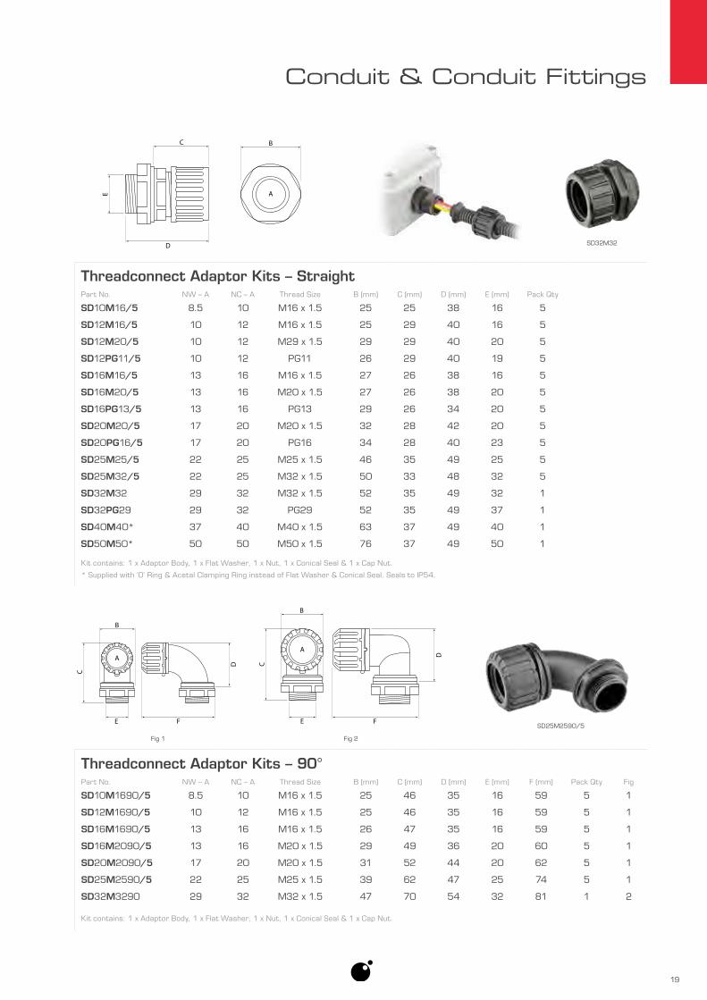
Conduit & Conduit Fittings
Threadconnect Adaptor Kits – StraightPart No. NW – A NC – A Thread Size B (mm) C (mm) D (mm) E (mm) Pack Qty
SD10M16/5 8.5 10 M16 x 1.5 25 25 38 16 5
SD12M16/5 10 12 M16 x 1.5 25 29 40 16 5
SD12M20/5 10 12 M29 x 1.5 29 29 40 20 5
SD12PG11/5 10 12 PG11 26 29 40 19 5
SD16M16/5 13 16 M16 x 1.5 27 26 38 16 5
SD16M20/5 13 16 M20 x 1.5 27 26 38 20 5
SD16PG13/5 13 16 PG13 29 26 34 20 5
SD20M20/5 17 20 M20 x 1.5 32 28 42 20 5
SD20PG16/5 17 20 PG16 34 28 40 23 5
SD25M25/5 22 25 M25 x 1.5 46 35 49 25 5
SD25M32/5 22 25 M32 x 1.5 50 33 48 32 5
SD32M32 29 32 M32 x 1.5 52 35 49 32 1
SD32PG29 29 32 PG29 52 35 49 37 1
SD40M40* 37 40 M40 x 1.5 63 37 49 40 1
SD50M50* 50 50 M50 x 1.5 76 37 49 50 1
Kit contains: 1 x Adaptor Body, 1 x Flat Washer, 1 x Nut, 1 x Conical Seal & 1 x Cap Nut.
* Supplied with ‘O’ Ring & Acetal Clamping Ring instead of Flat Washer & Conical Seal. Seals to IP54.
E
B
A
D
C
SD32M32
SD25M2590/5E
B
A
F
D
C
E
B
A
F
D
C
Fig 1 Fig 2
Threadconnect Adaptor Kits – 90°Part No. NW – A NC – A Thread Size B (mm) C (mm) D (mm) E (mm) F (mm) Pack Qty Fig
SD10M1690/5 8.5 10 M16 x 1.5 25 46 35 16 59 5 1
SD12M1690/5 10 12 M16 x 1.5 25 46 35 16 59 5 1
SD16M1690/5 13 16 M16 x 1.5 26 47 35 16 59 5 1
SD16M2090/5 13 16 M20 x 1.5 29 49 36 20 60 5 1
SD20M2090/5 17 20 M20 x 1.5 31 52 44 20 62 5 1
SD25M2590/5 22 25 M25 x 1.5 39 62 47 25 74 5 1
SD32M3290 29 32 M32 x 1.5 47 70 54 32 81 1 2
Kit contains: 1 x Adaptor Body, 1 x Flat Washer, 1 x Nut, 1 x Conical Seal & 1 x Cap Nut.

20
Conduit & Conduit Fittings
• Compatible with PA6 or PPmod Lockable conduit.
• ‘T’ Piece Locking version supplied with lock washer to prevent cap nut from coming loose.
• Seals to IP67 using supplied conical seal with PA6 conduit.
• Suitable for hazardous applications when used with PA6 conduit.
Adaptor Body : PolycarbonateConical Seal : NeopreneCap Nut : Polyamide 6Operating Temperature : -25°C to 80°C
Thre
adco
nnec
t Fi
ttin
gs
Adaptor Body
Conical Seal
Cap Nut
Threadconnect ‘T’ Piece KitsPart No.
NW NCMount Flange D (mm) E (mm) F (mm) Pack Qty
A B C A B C
SE10 8.5 8.5 8.5 10 10 10 No 74 50 24 1
SE12 10 10 10 12 12 12 No 80 53 24 1
SE20 17 17 17 20 20 20 Yes 76 54 32 1
SE25* 22 22 22 25 25 25 Yes 96 83 42 1
SE2520 22 22 17 25 25 20 Yes 96 53 42 1
Kit contains: 1 x Adaptor Body, 3 x Conical Seal & 3 x Cap Nut.
* Supplied with adaptor to achieve outlet size.
D
A
E
B
C
F
7mmMount Flange
D
A
E
B
CF
7mmMount Flange
CTPB28
SE20

21
Conduit & Conduit Fittings
Threadconnect ‘T’ Piece Kits – LockingPart No.
NW NCD (mm) E (mm) F (mm) Pack Qty
A B C A B C
CTP12 10 10 10 12 12 12 73 52 28 1
CTP16 13 13 13 16 16 16 75 53 31 1
CTPB20 17 17 17 20 20 20 82 60 36 1
CTPB28 22 22 22 25 25 25 98 71 43 1
Kit contains: 1 x Adaptor Body, 3 x Locking Washer, 3 x Conical Seal, 3 x Cap Nut & 1 x Adaptor Body Access Cap.
Not compatible with Threadconnect Reducers.
D
A
E
B
C
F
D
A
E
B
C
F
Adaptor Body Access Cap
Adaptor Body
Conical Seal
Lock Washer
Cap Nut
Threadconnect Manifold KitPart No.
NW NCE (mm) F (mm) G (mm) Pack Qty
A B C D A B C D
SE25X12 22 22 10 10 25 25 12 12 121 73 42 1
Kit contains: 1 x Adaptor Body, 4 x Conical Seal & 4 x Cap Nut.
E
A
F
B
C D
G
7mm35mm
E
A
F
B
C D
G
7mm35mm
Adaptor Body
Conical Seal
Cap Nut

22
Conduit & Conduit Fittings
• Compatible with PA6 or PPmod Lockable conduit.
• Seals to IP67 using supplied conical seal with PA6 conduit.
• Suitable for hazardous applications when used with PA6 conduit.
Conical Seal : NeopreneCap Nut : Polyamide 6
Thre
adco
nnec
t Red
ucer
s
Threadconnect Reducer KitsPart No. NW Size Reduction – A NC Size Reduction – A B (mm) C (mm) Pack Qty
SF1208/5 10 to 7.5 12 to 8 20 24 5
SF1612/5 13 to 10 16 to 12 22 26 5
SF2012/5 17 to 10 20 to 12 23 32 5
SF2016/5 17 to 13 20 to 16 23 32 5
SF2512/5 22 to 10 25 to 12 23 42 5
SF2516/5 22 to 13 25 to 16 23 42 5
SF2520/5 22 to 17 25 to 20 23 42 5
Kit contains: 1 x Reducer Seal & 1 x Cap Nut.
Not Compatible with Threadconnect ‘T’ Piece – Locking.
SF2520/5
Reducer Seal
Cap Nut
C B
A
SF1208/5
SF2516/5
SF1612/5

23
Conduit & Conduit Fittings
• Compatible with PA6, PPmod Lockable or PP Split conduit.
• Snap-lock clips for quick & easy assembly.
• Selected models feature mounting slot compatible with Mounting Clips – see page 27.
• Wide range of sizes.
• Reducers available for more size options – see page 27.
Material : Polyamide 66 (PA66)Operating Temperature : -40°C to 135°CIngress Protection : IP54
Hinged ‘T’ &
‘Y’ Fittings
T-PiecePart No. NW – A–B–C NC – A–B–C Mounting Slot Pack Qty
9806082/10 7.5 – 7.5 – 7.5 8 – 8 – 8 Yes 10
9806088/10 8.5 – 8.5 – 10 10 – 10 – 12 Yes 10
9806086/10 10 – 8.5 – 10 12 – 10 – 12 Yes 10
9806089/10 10 – 10 – 10 12 – 12 – 12 Yes 10
9806090/10 13 – 8.5 – 10 16 – 10 – 12 Yes 10
9806091/10 13 – 10 – 10 16 – 12 – 12 Yes 10
9806092/10 13 – 7.5 – 13 16 – 8 – 16 Yes 10
9806093/10 13 – 13 – 7.5 16 – 16 – 8 Yes 10
9806096/10 17 – 13 – 13 20 – 16 – 16 Yes 10
9806095/10 17 – 7.5 – 17 20 – 8 – 20 Yes 10
9806099/10 17 – 17 – 7.5 20 – 20 – 8 Yes 10
9806196/10 17 – 17 – 17 20 – 20 – 8 Yes 10
A C
B
9806097/10
9806090/10
Most Hinged Fittings feature a mounting slot.
Used with ST-CLIP page 27
9817203/10

24
Conduit & Conduit Fittings
Create Manifold Using Hook Up Outlet
T-Piece – Hook UpPart No. NW – A–B–C NC – A–B–C Hook Up Mounting Slot Pack Qty Fig
9806130/10 10 – 7.5 – 7.5 12 – 8 – 8 A No 10 1
9806131/10 13 – 10 – 10 16 – 12 – 12 A Yes 10 1
9806133/10 8.5 – 8.5 – 8.5 10 – 10 – 10 C Yes 10 2
9806111/10 10 – 7.5 – 10 12 – 8 – 12 C Yes 10 2
9806111/100 10 – 7.5 – 10 12 – 8 – 12 C Yes 100 2
9806160/10 10 – 10 – 7.5 12 – 12 – 8 C Yes 10 2
9806138/10 10 – 10 – 10 12 – 12 – 12 C Yes 10 2
9806138/100 10 – 10 – 10 12 – 12 – 12 C Yes 100 2
9806127/10 13 – 4.5 – 10 16 – 6 – 12 C Yes 10 2
9806158/10 13 – 7.5 – 13 16 – 8 – 16 C Yes 10 2
9806118/10 13 – 8.5 – 13 16 – 10 – 16 C Yes 10 2
9806172/10 13 – 10 – 7.5 16 – 12 – 8 C Yes 10 2
9806104/10 13 – 13 – 10 16 – 16 – 12 C Yes 10 2
9806159/10 13 – 13 – 7.5 16 – 16 – 8 C Yes 10 2
9806101/10 13 – 10 – 13 16 – 12 – 16 C Yes 10 2
9806115/10 13 – 13 – 13 16 – 16 – 16 C Yes 10 2
9806115/100 13 – 13 – 13 16 – 16 – 16 C Yes 100 2
Most Hinged Fittings feature a single outlet with a protruding ridged ring used to “hook up” with other Hinged Fittings creating manifolds.
This ridged ring simulates a piece of corrugated conduit allowing other Hinged Fittings, the next size up, to securely clamp down around it.
Hook Up CA
B
Fig 1 Fig 2
A C
B
Hook Up
9806131/10

25
Conduit & Conduit Fittings
T-Piece – Hook Up cont.
Part No. NW – A–B–C NC – A–B–C Hook Up Mounting Slot Pack Qty
9806137/10 17 – 7.5 – 17 20 – 8 – 20 C Yes 10
9806120/10 17 – 8.5 – 17 20 – 10 – 20 C Yes 10
9806136/10 17 – 10 – 17 20 – 12 – 20 C Yes 10
9806136/100 17 – 10 – 17 20 – 12 – 20 C Yes 100
9806107/10 17 – 10 – 13 20 – 12 – 16 C Yes 10
9806100/10 17 – 7.5 – 13 20 – 8 – 16 C Yes 10
9806166/10 17 – 13 – 13 20 – 16 – 16 C Yes 10
9806167/10 17 – 17 – 7.5 20 – 20 – 8 C Yes 10
9806141/10 17 – 13 – 17 20 – 16 – 20 C Yes 10
9806141/100 17 – 13 – 17 20 – 16 – 20 C Yes 100
9806135/10 17 – 22 – 17 20 – 25 – 20 C Yes 10
9806135/100 17 – 22 – 17 20 – 25 – 20 C Yes 100
9806103/10 22 – 17 – 13 25 – 20 – 16 C Yes 10
9806126/10 22 – 22 – 17 25 – 25 – 20 C No 10
9806114/10 22 – 13 – 17 25 – 16 – 20 C No 10
9806113/10 22 – 7.5 – 22 25 – 8 – 25 C No 10
9806149/10 22 – 8.5 – 22 25 – 10 – 25 C No 10
9806143/10 22 – 10 – 10 25 – 12 – 12 C No 10
9806121/10 22 – 10 – 22 25 – 12 – 25 C No 10
9806108/10 22 – 13 – 22 25 – 16 – 25 C No 10
9806108/100 22 – 13 – 22 25 – 16 – 25 C No 100
9806102/10 22 – 22 – 22 25 – 25 – 25 C No 10
9806124/10 26 – 17 – 13 30 – 20 – 16 C No 10
9806112/10 26 – 22 – 22 30 – 25 – 25 C No 10
9806110/10 26 – 26 – 22 30 – 30 – 25 C No 10
9806129/10 26 – 10 – 26 30 – 12 – 30 C No 10
9806146/10 26 – 17 – 26 30 – 20 – 30 C No 10
A C
B
Hook Up
9806121/10

26
Conduit & Conduit Fittings
Y-PiecePart No. NW – A–B–C NC – A–B–C Hook Up Mounting Slot Pack Qty Fig
9817083/10 7.5 – 4.5 – 7.5 8 – 6 – 8 — Yes 10 1
9817079/10 7.5 – 7.5 – 7.5 8 – 8 – 8 — Yes 10 2
9817079/100 7.5 – 7.5 – 7.5 8 – 8 – 8 — Yes 100 2
9817303/10 10 – 10 – 10 12 – 12 – 12 A Yes 10 3
9817303/100 10 – 10 – 10 12 – 12 – 12 A Yes 100 3
9817304/10 13 – 7.5 – 10 16 – 8 – 12 C Yes 10 4
9817306/10 13 – 10 – 10 16 – 12 – 12 C Yes 10 4
9817305/10 13 – 10 – 13 16 – 12 – 16 C Yes 10 4
9817305/100 13 – 10 – 13 16 – 12 – 16 C Yes 100 4
9817308/10 13 – 13 – 13 16 – 16 – 16 C Yes 10 4
SM200812/10 17 – 7.5* – 10 20 – 8* – 12 C Yes 10 4
9817310/10 17 – 13 – 10 20 – 16 – 12 C Yes 10 4
9817310/100 17 – 13 – 10 20 – 16 – 12 C Yes 100 4
9817309/10 17 – 17 – 10 20 – 20 – 12 C Yes 10 4
9817201/10 17 – 13 – 17 20 – 16 – 20 A No 10 5
9817201/100 17 – 13 – 17 20 – 16 – 20 A No 100 5
9817200/10 22 – 10 – 17 25 – 12 – 20 A No 10 5
9817203/10 22 – 13 – 17 25 – 16 – 20 A No 10 5
9817202/10 22 – 17 – 17 25 – 20 – 20 A No 10 5
SM251225/10 22 – 10* – 22 25 – 12* – 25 C No 10 4
9817311/10 22 – 13 – 22 25 – 16 – 25 C No 10 4
9817302/10 22 – 22 – 22 25 – 25 – 25 C No 10 4
* Reducer supplied to achieve outlet size.
Fig 5
Fig 3
Fig 4
9817201/10
9817079/10 9817303/109817083/10
Fig 1 Fig 2
9817311/10
B
A
C
B
A
C
B
A
C
Hook Up
B
A
C
Hook Up
B
A
C
Hook Up

27
Conduit & Conduit Fittings
Hinged Fitting ReducersPart No. NW Size Reduction NC Size Reduction Pack Qty Fig
7807270/10 8.5 to 4.5 10 to 6 10 1
7807272/10 10 to 4.5 12 to 6 10 1
7807276/10 10 to 7.5 12 to 8 10 1
7807288/10 10 to 8.5 12 to 10 10 2
7807278/10 13 to 7.5 16 to 8 10 1
7807280/10 13 to 10 16 to 12 10 1
7807296/10 17 to 13 20 to 16 10 2
7807282/10 22 to 17 25 to 20 10 1
Fig 1 Fig 2
Hinged Fitting Mounting ClipsPart No. Description Pack Qty
ST-CLIP/10 ‘Christmas Tree’ clip 10
10m
m
8mm
16m
m
22m
m
27mm
MountingDimensions
Ø 6.5mm


Fitting AccessoriesGrommets Bushes & Glands 30
Cable Ties 32
Clips & Clamps 34
Electrical Tape 38
Mémocab Marking System 39
Terminal Insulators/Boots 40

30
Fitting Accessories
Gro
mm
ets
Bus
hes
& G
land
s • Quick and simple cable retention without the use of tools.
• Acts as a strain relief.
Cable GrommetsPart No. Cable Ø
A (mm)Cutout Ø B (mm) C (mm) D (mm) Pack Qty
RG1-12/10 4 – 7 12.5 12.6 20 10
RG1-12/50 4 – 7 12.5 12.6 20 50
RG1-16/10 5 – 8 16 17.8 21 10
RG1-16/50 5 – 8 16 17.8 21 50
RG1-19/10 7 – 10 19 19.8 24 10
RG1-19/50 7 – 10 19 19.8 24 50
RG1-23/10 10 – 14 23 21.6 28 10
RG1-23/50 10 – 14 23 21.6 28 50
RG1-29/5 14 – 20 29 24.6 35 5
RG1-29/25 14 – 20 29 24.6 35 25
RG1-38/5 20 – 26 38 28.5 46 5
RG1-38/25 20 – 26 38 28.5 46 25
RG1-48/10 26 – 35 48 34.9 58 10
RG1-12/10
RG1-12/50
RG1-29/5
C D
0.5 - 4mm
BA
SB10/100
CG12/10
RG1-29/5

31
Fitting Accessories
Snap BushingPart No. Cable Ø
A (mm)Mounting Hole Ø
B (mm) C (mm) D (mm)
SB08/100 5.8 7.9 10.5 8.0
SB10/100 6.4 9.5 12.0 10.3
SB13/100 8.0 12.7 15.0 10.3
SB14/100 11.4 14.3 17.0 10.3
SB16/100 12.7 15.9 18.6 10.3
SB22/100 17.5 22.2 24.2 11.5
Pack quantity – 100.
Cable Gland KitsPart No. Clamping Range A (mm) Thread Size (B & C) D (mm) E (mm) Pack Qty
CG12/10 2.5 – 6.5 M12 x 8mm 30 19 10
CG16/10 3.5 – 10 M16 x 15mm 45 25 10
CG20/10 7 – 14 M20 x 15mm 48 29 10
CG25/10 9 – 18 M25 x 15mm 51 36 10
CG32/10 14 – 25 M32 x 15mm 55 46 10
CG40/5 18 – 32 M40 x 16mm 65 59 5
CG50 24 – 38 M50 x 16mm 72 67 1
CG63 35 – 48 M60 x 16mm 67 80 1
Kit contains:
1 x Adaptor Body 1 x Conical Seal 1 x Conical Clamp 1 x Cap Nut 1 x Flat Washer 1 x Nut
D
B A C
SB10/100
Cap Nut
Conical Clamp
Conical Seal
Adaptor Body
Flat Washer
Nut
B
D
C
A E
CG32/10
32
Fitting Accessories
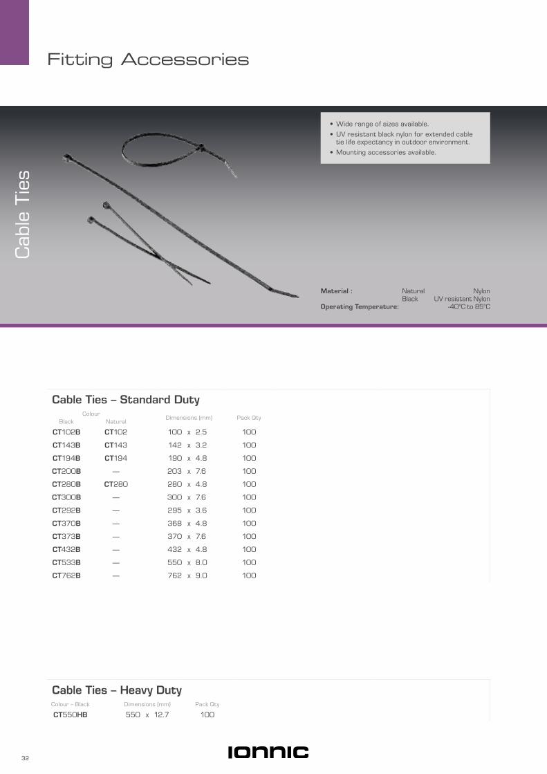
• Wide range of sizes available.
• UV resistant black nylon for extended cable tie life expectancy in outdoor environment.
• Mounting accessories available.
Material : Natural NylonBlack UV resistant Nylon
Operating Temperature: -40°C to 85°C
Cab
le T
ies
Cable Ties – Standard DutyColour
Dimensions (mm) Pack QtyBlack Natural
CT102B CT102 100 x 2.5 100
CT143B CT143 142 x 3.2 100
CT194B CT194 190 x 4.8 100
CT200B — 203 x 7.6 100
CT280B CT280 280 x 4.8 100
CT300B — 300 x 7.6 100
CT292B — 295 x 3.6 100
CT370B — 368 x 4.8 100
CT373B — 370 x 7.6 100
CT432B — 432 x 4.8 100
CT533B — 550 x 8.0 100
CT762B — 762 x 9.0 100
Cable Ties – Heavy DutyColour – Black Dimensions (mm) Pack Qty
CT550HB 550 x 12.7 100
33
Fitting Accessories
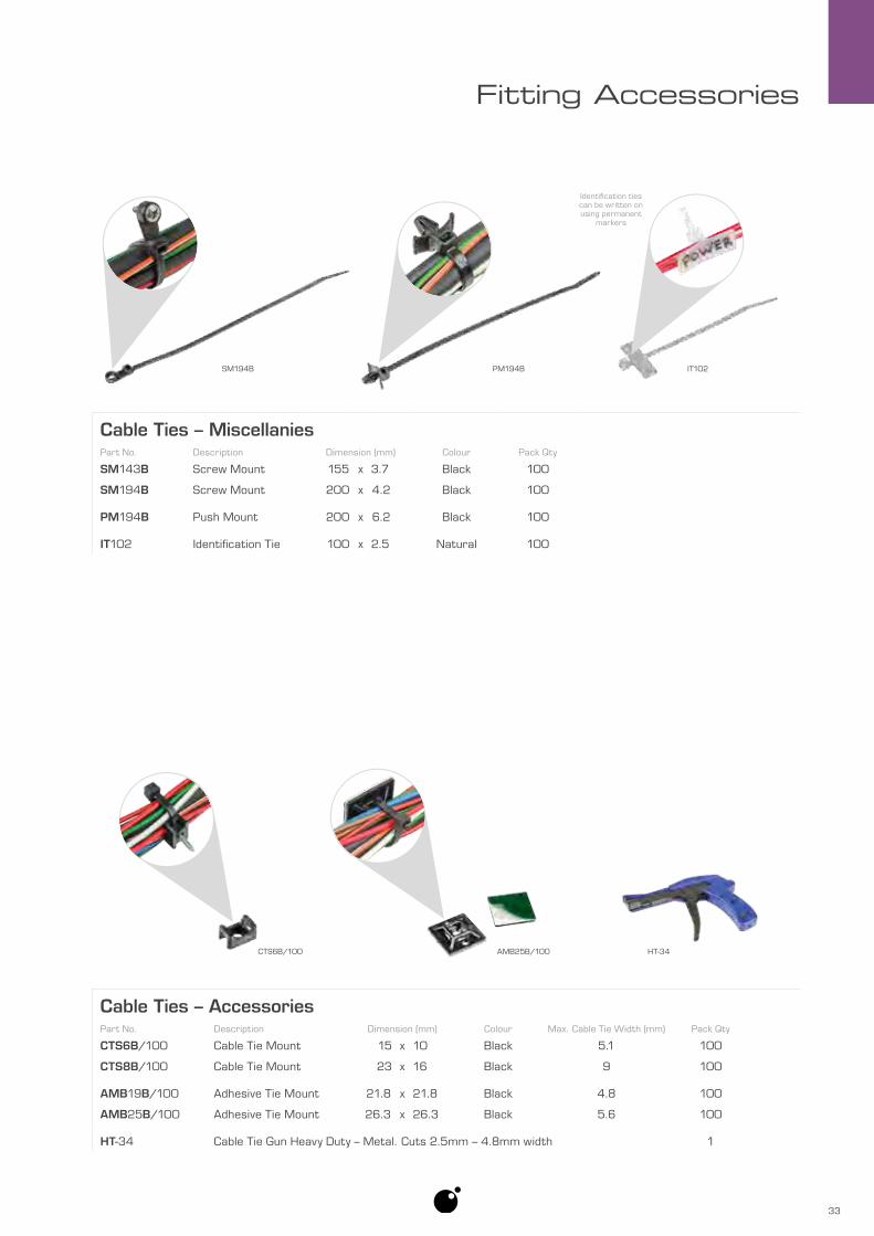
Cable Ties – AccessoriesPart No. Description Dimension (mm) Colour Max. Cable Tie Width (mm) Pack Qty
CTS6B/100 Cable Tie Mount 15 x 10 Black 5.1 100
CTS8B/100 Cable Tie Mount 23 x 16 Black 9 100
AMB19B/100 Adhesive Tie Mount 21.8 x 21.8 Black 4.8 100
AMB25B/100 Adhesive Tie Mount 26.3 x 26.3 Black 5.6 100
HT-34 Cable Tie Gun Heavy Duty – Metal. Cuts 2.5mm – 4.8mm width 1
Cable Ties – MiscellaniesPart No. Description Dimension (mm) Colour Pack Qty
SM143B Screw Mount 155 x 3.7 Black 100
SM194B Screw Mount 200 x 4.2 Black 100
PM194B Push Mount 200 x 6.2 Black 100
IT102 Identification Tie 100 x 2.5 Natural 100
SM194B PM194B
AMB25B/100 HT-34CTS6B/100
IT102
Identification ties can be written on using permanent
markers

34
Fitting Accessories
Clip
s &
Cla
mps
• Easy & secure one screw mounting option for one or multiple cables, conduit, hoses etc.
• High corrosion resistance.
• Electronically galvanised to a minimum thickness of 3 microns.
• Heavy Duty Hose Support Clamps feature 10mm mounting hole.
• Wide range of sizes available.
Hose Support Clamps – Rubber LinedPart No. A (mm) B (mm) C (mm) D (mm) Pack Qty
PS0.25/10 6 29 14 6.5 10
PS01/10 8 – 10 38 19 6.5 10
PS02/10 11 – 13 40 20 6.5 10
PS03/10 14 – 16 44 22 6.5 10
PS04/10 18 – 19 47 25 6.5 10
PS05/10 20 – 22 48 28 6.5 10
PS06/10 25 – 27 56 32 6.5 10
PS07/10 29 – 32 64 36 6.5 10
PS08/10 32 – 35 64 40 6.5 10
PS09/10 36 – 40 70 45 6.5 10
PS10/10 38 – 42 86 46 7 10
PS11/10 45 – 48 86 52 7 10
PS12/10 47 – 52 94 55 7 10
PS13/10 53 – 58 96 62 7 10
PS14/10 59 – 65 99 71 7 10
PS15/10 71 – 76 103 78 7 10
B
AC18
mm
DPS01/10 PS08/10
PS05/10
PSPHD09/10
8211035/10

35
Fitting Accessories
Hose Support Clamps – Plastic CoatedPart No. A (mm) B (mm) C (mm) D (mm) Pack Qty
PSP0.25/10 5 – 6 25 9 6.5 10
PSP0.5/10 7 – 8 28 12 6.5 10
PSP01/10 9 – 11 30 15 6.5 10
PSP02/10 12 – 14 34 17 6.5 10
PSP03/10 15 – 17 38 21 6.5 10
PSP04/10 18 – 20 42 23 6.5 10
PSP05/10 20 – 23 44 26 6.5 10
PSP06/10 25 – 28 52 30 6.5 10
PSP07/10 29 – 32 55 36 6.5 10
PSP08/10 33 – 37 60 38 6.5 10
PSP09/10 38 – 42 67 43 6.5 10
PSP10/10 42 – 46 76 47 6.5 10
PSP11/10 48 – 52 80 52 6.5 10
PSP12/10 53 – 57 87 57 6.5 10
PSP0.5/10 PSP05/10
B
AC15
mm
D

36
Fitting Accessories
Hose Support Clamps – Heavy Duty Plastic CoatedPart No. A (mm) B (mm) C (mm) D (mm) Pack Qty
PSPHD04/10 17 – 20 64 26 10 10
PSPHD05/10 19 – 21 66 28 10 10
PSPHD06/10 23 – 25 68 30 10 10
PSPHD07/10 24 – 26 71 32 10 10
PSPHD08/10 25 – 27 73 34 10 10
PSPHD09/10 27 – 29 76 36 10 10
PSPHD10/10 28 – 30 78 38 10 10
PSPHD11/10 31 – 34 78 38 10 10
PSPHD12/10 33 – 35 82 42 10 10
PSPHD13/10 35 – 38 85 44 10 10
PSPHD14/10 38 – 41 87 45 10 10
PSPHD15/10 39 – 42 89 47 10 10
PSPHD16/10 40 – 44 92 51 10 10
PSPHD17/10 42 – 46 94 53 10 10
PSPHD18/10 44 – 50 96 54 10 10
PSPHD05/10
PSPHD17/10B
AC26
mm
D
‘P’ Clamps – Light DutyPart No. A (mm) B (mm) C (mm) D (mm) E (mm) Pack Qty
PSN0.5/100 4 – 5 19 7 10 5.3 100
PSN01/100 5.5 – 6.5 21 8 10 5.3 100
PSN01.5/100 7.5 – 8.5 23 10 10 5.3 100
PSN02/100 9.5 – 10.5 27 13 13 5.3 100
PSN03/100 11 – 12 30 14 13 5.3 100
PSN04/100 15 – 16 35 18 13 5.3 100
PSN01/100 PSN03/100
B
C A
D E

37
Fitting Accessories
‘P’ Clamps – Heavy Duty – Polyacetal ResinPart No. A (mm) B (mm) C (mm) D (mm) E (mm) Pack Qty
8211060/10 5.7 – 6.3 28 10 16 6.6 10
8211094/10 8.6 – 9.3 30 14 16 6.6 10
8211108/10 9.5 – 10.3 32 15 16 6.6 10
8211124/10 11.5 – 12.3 34 17 16 6.6 10
8211000/10 12.3 – 13.3 36 18 16 6.6 10
8211035/10 15.5 – 16.3 38 21 16 6.6 10
8211019/10 21.4 – 22.3 47 27 19 6.6 10
8211027/10 24.4 – 25.3 58 32 23 8.6 10
B
C A
D E
8211019/10
8211094/10
Clips & ClampsPart No. Description Pack Qty
9620/10 Chassis Clips – Small 10
9621/10 Chassis Clips – Medium 10
9622/10 Chassis Clips – Large 10
BHS80 Battery Clamps – 7" bolts. Up to 175 wide 1
BHS81 Battery Clamps – 5.5" bolts. Up to 135mm wide 1
9620/10 BHS80

38
Fitting Accessories
• Chemical, weather and heat resistant.
• Excellent electrical insulation.
• PET cloth for high abrasion and temperature resistance – 150°C.
• PET fleece tape for flexibility and noise damping. Typical use in-cab.
• NO.15 self-fuses creating a seamless waterproof insulating layer.
PVCTBLK/10
HP-FT19
Electrical TapePart No. Material Length (m) Width (mm) Thickness (mm) Colour Elongation Pack Qty
HP-CT19 PET Cloth 25 19 0.26 Black 40% 1
HP-FT19 PET Fleece 25 19 0.28 Black 20% 1
NITTO21/10 PVC 20 19 0.2 Black 240% 10
PVCTBLK/10 PVC 20 19 0.19 Black 276% 10
PVCTWHT/10 PVC 20 19 0.19 White 100% 10
NO.15 Self-Fusing Butyl Rubber 10 19 0.5 Black 530% 1
Elec
tric
al T
ape
NITTO21/10 PVCTWHT/10HP-CT19
PET Cloth
HP-FT19
PET Fleece
NO.15

39
Fitting Accessories
Mémocab Marking System KitsPart No. Description Part No. Description
37994 Starter Kit 37999 Marking Kit
Kit Contains: Kit Contains:
1 3 1
50 50 50 4 1 1
x x x x x x x x x
Dispenser Board (37991), Selecting Prongs (37989, 37990, 37992), Extractor Tool (37993), 0.25–1.5mm2 Marker Holders (37930), 0.75–4mm2 Marker Holders (37931), 4–16mm2 Marker Holders (37932), "0–9" Markers, "A–Z" Markers, "/", "+", "–" Markers
1 2 1
50 50 50
x x x x x x
Dispenser Board (37991), Selecting Prongs (37990, 37992), Extractor Tool (37993), 0.25–1.5mm2 Marker Holders (37936), 0.75–4mm2 Marker Holders (37937), 4–16mm2 Marker Holders (37938)
Individual marker characters available separately. See component reference chart inside case for listing.
37994
Coloured markers also available, for details contact your nearest
reseller 1800 724 690.
Marker Holders
37989
37993
37990
37992
Selecting Prongs
Extractor ToolDispenser Board filled with markers37994, 37999 Markers
Cable Range : 0.25mm2 – 16mm2
• Efficient, professional cable marking system.
• Supplied with everything needed to tag wiring.
• Handy dispenser case allows quick and easy selection of markers using supplied tools.
• Component reference chart included.
Mém
ocab Marking S
ystem

40
Fitting Accessories
• Protect terminals from electrical shorts and shocks.
• Colour coded for easy pole identification.
• Wide range of sizes & styles available.
• 200 Series feature finger tab for easy remove.
• Bulk packs available for entire range.
Term
inal
Insu
lato
rs
Material : Flexible PVCMax. Operating Temperature : 105°CBurning Behaviour : UL94V2
SY2912-RED
SY2917-RED
SY2990-BLK
SY2965-BLK
Battery Terminal InsulatorsRed Black Pack Qty Post Height
(mm)Cable Ø A (mm) Cable Entry Material
Thickness (mm)
SY2912-RED SY2912-BLK 125 17.5 Right Hand 2.3
SY2912R/100 SY2912B/100 100
SY2914-RED SY2914-BLK 125 17.5 Left Hand 2.3
SY2914R/100 SY2914B/100 100
39.5mm
56m
m20
mm
A
A
39.5mm
56m
m20
mm
A
A
A
A
25m
m61
mm
47mm
A
A
25m
m61
mm
47mm 47mm
A
A
A
A
25m
m61
mm
Battery Terminal Insulators – Straight LeadsRed Black Pack Qty Post Height
(mm)Cable Ø A (mm)
Material Thickness (mm)
SY2917-RED SY2917-BLK 119 12.5 2.3
SY2917R/100 SY2917B/100 100
SY2919-RED SY2919-BLK 119 16 2.3
SY2919R/100 SY2919B/100 100
82.5mm
19m
m35
.5m
m
A
A
SY2912 SY2914

41
Fitting Accessories
Terminal Insulators – Lug & RingRed Black Pack
QtyTerminal Ø
(mm)Post Height
(mm)Terminal
Length (mm)Inside Grip
(mm)Cable Ø (mm)
Material Thickness (mm)
SY2900-RED SY2900-BLK 113 16 21 6 4 – 6 1
SY2900R/100 SY2900B/100 100
SY2980-RED SY2980-BLK 118.5 26 33.5 10.5 8 1.5
SY2980R/100 SY2980B/100 100
13m
m16
mm
6mm
4mm
21mm
SY2980SY2900
33.5mm
26m
m
10.5
mm
8mm
18.5
mm
Battery Terminal InsulatorsRed Black Pack Qty Terminal Ø
(mm)Post Height
(mm)Material
Thickness (mm)
SY2990-RED SY2990-BLK 130.5 23 2
SY2990R/100 SY2990B/100 100
36mm
30.5mm
87mm
14m
m
19m
m19
mm
38m
m
48.5
mm
23m
m
36mm
30.5mm
87mm
14m
m
19m
m19
mm
38m
m
48.5
mm
23m
m36mm
30.5mm
87mm
14m
m
19m
m19
mm
38m
m
48.5
mm
23m
m
Terminal Insulators – Lug & Ring – 200 SeriesRed Black Pack
QtyTerminal Ø
A (mm)Post Height
B (mm)Terminal Length
C (mm)Inside Grip
D (mm)Cable Ø
FigMaterial
Thickness (mm)
SY2960-RED SY2960-BLK 114 19 25.5 12.5 1 1.5
SY2960R/100 SY2960B/100 100
SY2965-RED SY2965-BLK 118 22 25.5 12.5 2 1.5
SY2965R/100 SY2965B/100 100
SY2968-RED SY2968-BLK 122 26.5 44.5 19 3 1.8
SY2968R/100 SY2968B/100 100
SY2971-RED SY2971-BLK 126 32 52.5 18 3 2
SY2971R/100 SY2971B/100 100
SY2970-RED SY2970-BLK 128 33.5 44.5 19 3 2.3
SY2970R/100 SY2970B/100 100
SY2975-RED SY2975-BLK 132 38 44.5 23 4 2.5
SY2975R/100 SY2975B/100 100
B
A
D
C
6mm
3.5m
m
23m
m
18m
m
12.5
mm
7.5m
m
17.5
mm
12.5
mm
Cable Ø
Fig 1 Fig 2 Fig 3 Fig 4
6mm
3.5m
m
23m
m
18m
m
12.5
mm
7.5m
m
17.5
mm
12.5
mm
6mm
3.5m
m
23m
m
18m
m
12.5
mm
7.5m
m
17.5
mm
12.5
mm
6mm
3.5m
m
23m
m
18m
m
12.5
mm
7.5m
m
17.5
mm
12.5
mm


SleevingPVC Tubing 44
Flexible Braiding 45
Flexible Braiding – Nylon 46
High Temp Sleeving 47
Spiral Wrap 48
Standard Wall Heatshrink 50
Adhesive-lined Heatshrink 53

44
Sleeving
• General all around harness protection.
• Self-extinguishing fire retardant PVC.
• Wide range of lengths & sizes available.
PVC T
ubin
g
Tubing : Flexible V75 Cable Grade PVCBurning Behaviour : Self-extinguishingHardness : Shore A 92Operating Temperature : Continuous 75°C
PVC TubingRoll Length – 25m Roll Length – 50m Roll Length – 100m Roll Length – 200m Roll Length – 250m Inside Ø – A (mm) Wall Thickness (mm)
PVC4/25 — — — PVC4/250 4 0.5
PVC6/25 — — PVC6/200 — 6 0.5
PVC8/25 — — PVC8/200 — 8 0.65
PVC10/25 — — PVC10/200 — 10 0.65
PVC12/25 — PVC12/100 — — 12 0.85
PVC16/25 — PVC16/100 — — 16 0.85
— PVC20/50 PVC20/100 — — 20 0.85
— PVC25/50 — — — 25 0.85
— PVC30/50 — — — 30 1.0
— PVC35/50 — — — 35 1.0
— PVC40/50 — — — 40 1.0
PVC8/25 PVC35/50A

45
Sleeving
• Extremely flexible & easy to apply over irregular shapes.
• Open weave construction allows for complete drainage.
• Salt, oil, most fuels, solvent and abrasion resistant.
• Broad operating temperature.
• Wide range of lengths & sizes available.
Flexible Braiding
Material : Braided Polyethelene TerephthalateBurning Behaviour : UL225, method VFW-1Operating Temperature -70°C to 120°C
Flexible BraidingRoll Length – 10m Roll Length – 50m Normal Size (mm) Expanded Size (mm)
— SZ0208/50 3.2 13
— SZ0616/50 6.4 15
— SZ1226/50 12.7 28
— SZ2040/50 19 35
— SZ2850/50 32 58
SZ3670/10 SZ3670/50 36 70
HT-19 Electric Knife
HT-19

46
Sleeving
Flex
ible
Bra
idin
g –
Nylon
• Self-extinguishing, flame retardant & halogen free.
• Extremely flexible & easy to apply over irregular shapes.
• Open weave construction allows for complete drainage.
• High abrasion, chemical, oil & solvent resistance.
• Broad operating temperature.
Material : Polyamide 6.6Operating Temperature : -60°C to 150°C
Peak 160°CMelting Point : 250°CBurning Behaviour : UL94 V2, FMVSS 302
Self-extinguishing Type A, D45 1333Approvals : RoHS
Flexible Braiding – NylonRoll Length – 25m Normal Size (mm) Expanded Size (mm)
SZPLA0308/25 3 8
SZPLA0514/25 5 14
SZPLA0819/25 8 19
SZPLA1124/25 11 24
SZPLA1430/25 14 30
HT-19 Electric Knife
SZPLA1430/25
SZPLA0819/25SZPLA0308/25
Normal Size
Expended SizeHT-19

47
Sleeving
High Temp SleevingRoll Length – 50m* Inside Ø – A (mm) Wall Thickness (mm)
VF4BLK/50 4.6 0.6
VF6BLK/50 6.6 0.6
VF8BLK/50 8.8 0.8
VF10BLK/50 10.8 0.8
VF12BLK/50 12.8 0.8
VF15BLK/50 15.8 0.8
VF20BLK/50 20.8 0.8
* Due to the manufacturing process, continuous length cannot be guaranteed.
• Withstands temperatures of up to 250°C.
• Braided E glass.
• Elastomer coated.
• Good flexibility.
• Resistance against: – ozone – ultraviolet radiation – humidity
• Compliant to 2002/95/EC (RoHS) directive.
• Wide range of lengths & sizes available.
High Tem
p Sleeving
Material : E GlassCoating : Silicone ElastomerBreakthrough Voltage : 7kV @ 20°CApprovals : 2002/95/EC (RoHS)Operating Temperature : Short Term 250°C
A

48
Sleeving
Spi
ral W
rap
• Light-weight and easy to use harness protection system.
• Excellent electrical, abrasive and binding strength.
• Flexible construction enables the easy routing of wiring looms.
• Durable and reusable.
Material : Nylon
Spiral WrapRoll Length – 10m Wrapping Range (mm) Outside Ø – A (mm) Wall Thickness – B (mm) Wrap Width – C (mm)
CTC-3B/10 1.5 – 10 3 0.5 4.7
CTC-6B/10 4 – 15 6 0.6 6.7
CTC-12B/10 9 – 32 12 0.85 15.0
CTC-16B/10 12 – 35 16 1.0 15.5
CTC-24B/10 20 – 100 24 1.3 21.5
B
A
C
CTC-12B/10
Catalogues

CataloguesCataloguesSafety
• White Sound Reversing Alarms
• Tonal Reversing Alarms• CCTV Systems• Obstacle Detection• Horns & Buzzers• Sirens & Intercoms
RAS2017
RA
S 2
017
Reversing & Audible
Safety
To get your copy visit ionnic.com
Lighting | Safety | Electrical
• J1939 CAN • Ultraview Touch Series• System Managers• 1-Touch Switch Panel• Sentry Governors• Twister• Total Pressure
Governors• Intelli-Tank Gauges• Vehicle Data Recorder
To get your copy visit ionnic.com
1
1
Electrical

50
Sleeving
Sta
ndar
d W
all H
eats
hrin
k
Tubing : PolyolefinShrink Temperature : 95°CDielectric Strength : >20kV/mmOperating Temperature : -55°C to 125°C
• Available in assortment kits, cut length packs, rolls and dispenser boxes.
• Reliable and cost-effective for standard duty electrical applications.
• 2:1 shrink ratio covers wide range of applications.
• Highly resistant to decay, chemicals, copper corrosion and ultra violet rays.
• Lightweight & flexible.
Heatshrink Application
Apply heat thoroughly to the entire strip using hot air gun or similar tool.
Depending on the type of heatshrink used, the shrink ratio will be at least 2:1.
Standard Wall Heatshrink Specifications
Part No. Prefix Diameter (mm)
Recovered Diameter (mm)
Recovered Wall Thickness (mm)
DHSR1.5 1.5 0.75 0.36
DHSR2.5 2.5 1.2 0.44
DHSR3.5 3.5 1.7 0.44
DHSR5 5 2.5 0.56
DHSR7 7 3.5 0.56
DHSR10 10 5 0.56
DHSR13 13 6.5 0.69
DHSR20 20 10 0.78
DHSR25 25 12.5 0.86
DHSR30 30 15 0.86
DHSR40 40 20 0.96
DHSR50 50 25 0.96
DHSX76 76 38 1.27
DHSR100 100 50 1.4
Cut length of heatshrink allowing for approximately 10mm of overlap.
10mm 10mm

51
Sleeving
2:1 Standard Wall Heatshrink – 40mm/50mm LengthsRed Black Pack Qty Cut Length (mm)
HS10-40RED/40 HS10-40BLK/40 40 40
HS13-40RED/40 HS13-40BLK/40 40 40
HS20-40RED/20 HS20-40BLK/20 20 40
HS25-50RED/10 HS25-50BLK/10 10 50
2:1 Standard Wall Heatshrink – 40mm/50mm Assortment KitPart No. Contents:
HS-KIT 20 x HS10 (black) 40 x HS10 (red)
20 x HS13 (black) 40 x HS13 (red)
10 x HS20 (black) 20 x HS20 (red)
10 x HS25 (black) 20 x HS25 (red)
2:1 Standard Wall Heatshrink – Dispenser Boxes Red Black Roll Length (m)
HSD2.5RED/20 HSD2.5BLK/20 20
HSD3.5RED/20 HSD3.5BLK/20 20
HSD5RED/10 HSD5BLK/10 10
HSD7RED/10 HSD7BLK/10 10
HSD10RED/10 HSD10BLK/10 10
HSD13RED/5 HSD13BLK/5 5
HSD20RED/5 HSD20BLK/5 5
HSD25RED/5 HSD25BLK/5 5

52
Sleeving
2:1 Standard Wall Heatshrink – RollsRed Black Length (m)
HSR1.5RED/200 HSR1.5BLK/200 200
HSR2.5RED/200 HSR2.5BLK/200 200
HSR3.5RED/200 HSR3.5BLK/200 200
HSR5RED/100 HSR5BLK/100 100
HSR7RED/50 HSR7BLK/50 50
HSR10RED/50 HSR10BLK/50 50
HSR13RED/50 HSR13BLK/50 50
HSR20RED/50 HSR20BLK/50 50
HSR25RED/50 HSR25BLK/50 50
HSR30RED/50 HSR30BLK/50 50
HSR40RED/25 HSR40BLK/25 25
HSR50RED/25 HSR50BLK/25 25
HSR100RED/25 HSR100BLK/25 25
2:1 Standard Wall Heatshrink – 1.2m LengthsRed Black Red Black
HS1.5RED HS1.5BLK HS20RED HS20BLK
HS2.5RED HS2.5BLK HS25RED HS25BLK
HS3.5RED HS3.5BLK HS30RED HS30BLK
HS5RED HS5BLK HS40RED HS40BLK
HS7RED HS7BLK HS50RED HS50BLK
HS10RED HS10BLK HS76RED HS76BLK
HS13RED HS13BLK

53
Sleeving
Adhesive-lined H
eatshrink
Tubing : PolyolefinShrink Temperature : 95°C
Thick Wall 105°CDielectric Strength : >15kV/mm
Medium Wall >20kV/mmOperating Temperature : Dual Wall -55°C to 80°C
Medium Wall, Thick Wall -55°C to 110°C
• Available in assortment kits, cut length packs and rolls.
• Adhesive lining for ultra secure connection from cable to connector & protection against harsh environment.
• Wide range of shrink ratios and sizes.
• Flame-retardant & mechanically tough.
• Lightweight & flexible.
• Strain Relief Sleeves – Provides extremely secure connection between cable and connector with the highest level of physical protection.
Thick adhesive liner forms an effective
barrier against ingress
3:1 Dual Wall Heatshrink Specifications
Part No. Prefix Diameter (mm)
Recovered Diameter (mm)
Recovered Wall Thickness (mm)
DW3 3 1 0.95
DW4.8 4.8 1.6 1.1
DW6 6 2 1.15
DW9 9 3 1.3
DW12 12 4 1.4
DW18 18 6 1.6
DW24 24 8 1.9
DW39 39 13 2.5
Recovered wall thickness excludes adhesive.
3:1 Dual Wall Heatshrink – 40mm/50mm Assortment KitPart No. Contents:
DW-KIT 20 x DW9 (black) 20 x DW9 (red)
20 x DW12 (black) 20 x DW12 (red)
20 x DW18 (black) 20 x DW18 (red)
20 x DW24 (black) 20 x DW24 (red)
54
Sleeving
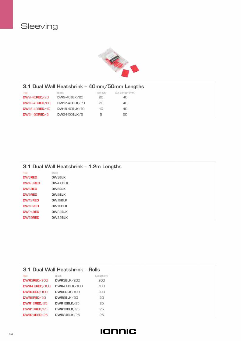
3:1 Dual Wall Heatshrink – RollsRed Black Length (m)
DWR3RED/200 DWR3BLK/200 200
DWR4.8RED/100 DWR4.8BLK/100 100
DWR6RED/100 DWR6BLK/100 100
DWR9RED/50 DWR9BLK/50 50
DWR12RED/25 DWR12BLK/25 25
DWR18RED/25 DWR18BLK/25 25
DWR24RED/25 DWR24BLK/25 25
3:1 Dual Wall Heatshrink – 1.2m LengthsRed Black
DW3RED DW3BLK
DW4.8RED DW4.8BLK
DW6RED DW6BLK
DW9RED DW9BLK
DW12RED DW12BLK
DW18RED DW18BLK
DW24RED DW24BLK
DW39RED DW39BLK
3:1 Dual Wall Heatshrink – 40mm/50mm LengthsRed Black Pack Qty Cut Length (mm)
DW9-40RED/20 DW9-40BLK/20 20 40
DW12-40RED/20 DW12-40BLK/20 20 40
DW18-40RED/10 DW18-40BLK/10 10 40
DW24-50RED/5 DW24-50BLK/5 5 50

55
Sleeving
4:1 Dual Wall Heatshrink – 1.2m LengthsBlack Ø (mm) Recovered Ø (mm) Recovered Wall Thickness (mm)
ES2000-1 5.7 1.3 0.7
ES2000-2 7.5 1.7 0.8
ES2000-3 11 2.4 0.9
ES2000-4 18 4.5 1.0
Recovered wall thickness excludes adhesive.
4.5:1 Thick Wall Heatshrink – Strain Relief SleevesBlack Ø (mm) Recovered Ø (mm) Recovered Wall Thickness (mm) Length (mm)
SRS43 43 10 3.5 140
Recovered wall thickness excludes adhesive.
Strain Relief Sleeve Application
Place Strain Relief Sleeve over cable as shown with the 15mm slip-free area covering part of connector.
Apply heat starting at the connector end. The 15mm adhesive free area will grip to connector providing a reliable connection for the remaining shrink.
Strain Relief Sleeves shrink down to approximately 1/4 of original size.
3.5:1 Medium Wall Heatshrink – 1.2m LengthsBlack Ø (mm) Recovered Ø (mm) Recovered Wall Thickness (mm)
MW12 12 3 1.5
MW22 22 6 2.5
MW27 27 8 2.5
MW35 35 9 2.5
MW40 40 12 2.5
MW56 56 17 2.5
MW72 72 22 2.5
Recovered wall thickness excludes adhesive.


EnclosuresABS/Thermoplastic 58
PVC 62
Die-cast 63
Pendant Control 64
Fuel Junction 66
Engraved Panels 67

58
Enclosures
• Lightweight & compact.
• Corrosion resistant.
• Environmentally sealed.
• Hinged lid models feature pre-fitted offset mounting plate.
• All enclosures incorporate moulded mounting points, excluding Hinged lid models.
• Ideal for terminal boxes, control boxes, power distribution panels and instrument containers.
• Supplied with sealing gasket.
Hinge & Latch : Stainless SteelOperating Temperature : -40°C to 120°C
SBA1212S
SBH2020
ABS/
Ther
mop
last
ic
ABS Enclosures – SBB SeriesPart No. A (mm) B (mm) C (mm) D (mm) SBB0812 80 120 40 14
SBB1010 100 100 40 14
SBB1115 150 110 49 25
SBB1924 240 190 70 26
SBB2230 300 220 76 50
DB
A
C
SBB2230
SBB0812

59
Enclosures
ABS Enclosures – Screw LidPart No. A (mm) B (mm) C (mm) D (mm) SBA0712 125 75 50 25
SBA0811 110 80 50 20
SBA1010 100 100 55 20
SBA1212 125 125 80 20
SBA1212S 125 125 55 20
SBA1217 175 125 50 25
SBA1417 170 140 75 20
SBA1525-1 250 150 80 50
DB
A
C
SBA1212S
ABS Enclosures – H SeriesPart No. A (mm) B (mm) C (mm) D (mm) H0300 60 65 25 15
H0301 75 105 25 15
H0302 80 85 40 15
H0304 85 125 40 15
H0306 85 165 40 15
H0308 125 165 60 15
H0310 146 186 60 15
H0306
DB
A
C

60
Enclosures
ABS Enclosures – Hinged LidPart No. A (mm) B (mm) C (mm) D (mm) SBH1212S 125 125 55 20
SBH1217 175 125 50 25
SBH2020 200 200 120 20
SBH2819-1 280 190 100 80
SBH2020
B
A
DC
Thermoplastic Enclosures – 50 SeriesPart No. A (mm) B (mm) C (mm) D (mm) 50856 113 113 40 17
50860 113 79 40 17
50861 113 113 70 17
50862 119 161 56 17
50864 170 145 69 17
50866 230 180 64 17
50868 322 250 113 17
50870 170 145 70 88
50872 230 180 72 88
B
A
CD
5086650860

61
Enclosures
SIPR01 SIPR02
IONNIC Potting BoxPart No. Description Profile SIPR01 Open top enclosure ideal for use with epoxy resin Low
SIPR02 Open top enclosure ideal for use with epoxy resin High
112mm
20m
m
83mm
47m
m
53m
m
Ø 4mm
103mm
38m
m48
mm
54m
m
73mm Ø 4mm
62
Enclosures
PVC
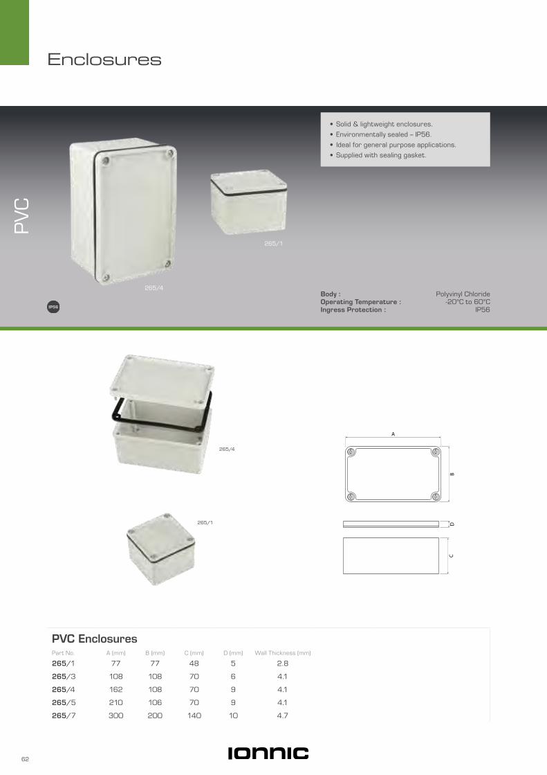
• Solid & lightweight enclosures.
• Environmentally sealed – IP56.
• Ideal for general purpose applications.
• Supplied with sealing gasket.
Body : Polyvinyl ChlorideOperating Temperature : -20°C to 60°CIngress Protection : IP56
PVC EnclosuresPart No. A (mm) B (mm) C (mm) D (mm) Wall Thickness (mm) 265/1 77 77 48 5 2.8
265/3 108 108 70 6 4.1
265/4 162 108 70 9 4.1
265/5 210 106 70 9 4.1
265/7 300 200 140 10 4.7
265/4
265/1
265/4
265/1
CD
B
A

63
Enclosures
Die-cast EnclosuresPart No. A (mm) B (mm) C (mm) D (mm) E (mm) Wall Thickness (mm) Fig H0420 89 53 30 100 — 1.4 1
H0421 114 64 30 127 30 1.4 2
H0422 114 64 55 127 30 1.4 2
H0423 114 90 55 127 50 1.8 2
H0424 120 100 35 137 60 1.8 2
H0427 171 121 55 189 80 1.8 2
H1590* 197 120 37 202 92 2.5 2
H0429 222 146 55 238 98 2.2 2
* Powder coated black. Not supplied with sealing gasket. Not IP66.
Die-cast
• Industrial grade heavy duty die-cast.
• Flanged base for easy mounting.
• High impact, corrosion resistant.
• Wide range of sizes.
• Environmentally sealed – IP66.
• Ideal for mining, industrial, agricultural and marine use.
• Supplied with sealing gasket.
Body : Die-cast AluminiumOperating Temperature : -40°C to 100°CIngress Protection : IP66
C
A
D
BE
Fig 2
C
A
D
B
Fig 1
H0420
H0423
H0429
H0429
H0420
H1590

64
Enclosures
• Configurable to personal requirements.
• Engraved face plate available on request.
• Wide range of toggle switches available to integrate.
Pen
dant
Con
trol
Body : Polyurethane
Pendant ControlPart No. Description HC1 Hand controller body
FP Face plate – black
FP2 Face plate – 2 hole. 8mm switch hole
FP3 Face plate – 3 hole. 8mm switch hole
CG16SR IP68 strain relief adaptor – 5mm to 10mm
Requires 7 x 8mm screws for face plate.
Engraved face plates available on request.
Example shown with toggle switches installed
FP2
FP3
FP
CG16SRHC1
88mm
70m
m
145mm
205m
m
Ø 6mm

65
Enclosures
Compatible Suzi Coils – 7 CorePart No. Cores - Qty x mm2 Tails Working Length (m) Fig
RC013 7 x 0.5 Tangent 3 1
RC014 7 x 0.5 Tangent 2 1
RC031 7 x 1.5 Tangent 8 2
RC032 1 x 2, 6 x 1 Tangent 3 3
RC022 7 x 0.75 Tangent with 1 x N12 plug 7.5 4
Compatible Toggle SwitchesPart No. Action Terminal Style Maximum Load @ 24V (A)
TS403AOFF
ON
Screw 15 0
TS403E Blade 15
MTS403 Screw 20
TS508AOFF
Mom.ON
Screw 15 0
MTS508 Screw 15
TS401AON
ON
Screw 15 0
TS401E Blade 15
MTS401 Screw 20
TS101A ON
OFF
ON
Screw 15 0
TS101E Blade 15
MTS101 Screw 20
TS301A Mom.ON
OFF
Mom.ON
Screw 15 0
TS301E Blade 15
MTS301 Screw 15
Fig 1
RC022
Fig 2
Fig 3 Fig 4 N12 Plug
Tangent
Tangent
7 Pin N12 Plug
Tangent Tangent
1.5
1.5
1.5
1.5
1.5
1.5
1.5
0.5
0.5
0.5
0.5
0.5
0.5
0.5
2
1
1
1
1
1
1
0.75
0.75
0.75
0.75
0.75
0.75
0.75
MTS403 with 8497K1 switch
guard fitted
TS101A with P23 name plate fitted Other Toggle
Switch accessories available, visit
ionnic.com to find out more
TS301E with TB001-BLK full
boot fitted

66
Enclosures
• Environmentally sealed – IP67.
• Integrated Threadconnect fitting.
Body : PolyoxymethyleneSeal : PerbunaneOperating Temperature : -25 °C to 80°CIngress Protection : IP67
Fuel
Jun
ctio
n
Fuel Junction Enclosure KitPart No. NW (A) NC (A)
ST01 10 12
Kit contains: 1 x Housing, 1 x Lid Seal, 1 x Lid, 1 x Cap Nut, 1 x Conical Seal
Cap Nut
Lid
Lid Seal
Housing
Conical Seal
120mm
97mm
93mm
109mm
Ø 6mm
42m
m
80m
m
A
Ø 5mm
67
Enclosures
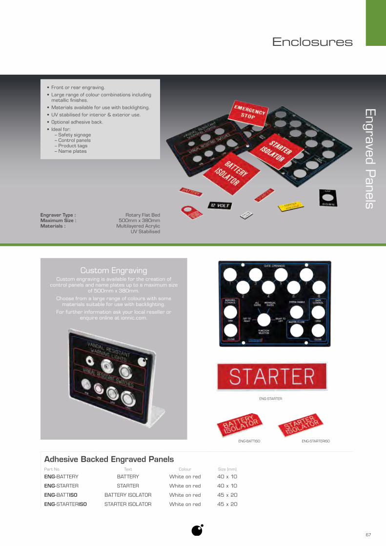
Engraver Type : Rotary Flat BedMaximum Size : 500mm x 380mmMaterials : Multilayered Acrylic
UV Stabilised
• Front or rear engraving.
• Large range of colour combinations including metallic finishes.
• Materials available for use with backlighting.
• UV stabilised for interior & exterior use.
• Optional adhesive back.
• Ideal for: – Safety signage – Control panels – Product tags – Name plates
Custom EngravingCustom engraving is available for the creation of
control panels and name plates up to a maximum size of 500mm x 380mm.
Choose from a large range of colours with some materials suitable for use with backlighting.
For further information ask your local reseller or enquire online at ionnic.com.
Engraved Panels
Adhesive Backed Engraved PanelsPart No. Text Colour Size (mm)
ENG-BATTERY BATTERY White on red 40 x 10
ENG-STARTER STARTER White on red 40 x 10
ENG-BATTISO BATTERY ISOLATOR White on red 45 x 20
ENG-STARTERISO STARTER ISOLATOR White on red 45 x 20
ENG-BATTISO ENG-STARTERISO
ENG-STARTER

Circuit Breaker TypesAutomatic Reset
The circuit breaker cycles continuously during an overload condition until the overload is removed or corrected.
Modified Reset
The circuit breaker contains an additional resistive component that causes the device to remain open as long as power is available.
Manual Reset
The circuit breaker contains a trip indicator button or lever that must be manually activated to return the device to normal operation.
Switchable
Circuit breaker operation is the same as ‘Manual Reset’ but with the additional trip button or lever allowing the user to disable the circuit.
Circuit ProtectionCircuit Breakers – General 70
Circuit Breakers – Heavy Duty 72Circuit Breakers – Marine 74Circuit Breakers – Toggle 75Circuit Breakers – Blade 76
Fuses 78Fuse Holders 82
Blade Fuse Tap 85Power Distribution Modules 86
Mini Electrical Centres 88Modular MFL Fuse Holder 90
Bolt-in Fuses 92Bolt-in Fuse Holders 94
Modular AMI Fuse Holder 97Plug-in Diodes 98
Diodes 99

70
Circuit Protection
174 Series – Panel MountCurrent Rating
10A 15A 30A
CB174-10 CB174-15 CB174-30
Manual Reset.
14m
m
37m
m
24m
m
29mm
24mm
Ø 11mm
6mm
S55 Series – Panel MountCurrent Rating
3A 5A 10A 15A 20A 25A 30A 35A
S5503 S5505 S5510 S5515 S5520 S5525 S5530 S5535
S55BOOT Protective boot
Manual Reset.
Not a Bussmann product.
35mmØ 11.5mm
15m
m
54m
m
31m
m
24mm
6mmS55BOOT
• Panel or surface mount option.
• Compact size.
• Manual or automatic reset methods.
• Broad operating temperature.
• Ideal for trucks, buses, RV's. portable generators, battery chargers.
Material : 174, S55, CDM Series ThermoplasticIngress Protection : 174, S55 Series IP54
CDM Series IP66Operating Temperature : -40°C to 85°CApprovals : SAE J1171
174, S55 Series UL & CSA174, 121/123, CDM Series SAE J553C
ircu
it Bre
aker
s –
Gen
eral
CB121-20
S5505
CDM30

71
Circuit Protection
CDM Series – Panel MountCurrent Rating
3A 5A 10A 15A 20A 30A 40A 60A
CDM03 CDM05 CDM10 CDM15 CDM20 CDM30 CDM40 CDM60
Manual Reset.
Not a Bussmann product.
32m
m
40mm
33m
m10
mm13mmØ 4mm51mm
23m
m
121 Series – Surface MountCurrent Rating
Material 8A 10A 15A 20A 25A 30A 40A 50A
Plastic CB121-8 CB121-10 CB121-15 CB121-20 CB121-25 CB121-30 CB121-40 CB121-50
Metal — CB121-10M CB121-15M CB121-20M CB121-25M CB121-30M CB121-40M CB121-50M
123 Series – Surface Mount Current Rating
Material 8A 10A 15A 20A 25A 30A 40A 50A
Plastic — CB123-10 CB123-15 CB123-20 CB123-25 CB123-30 CB123-40 —
Manual Reset.
Accessories – 121/123 Series – BootsRed Black
CB121BOOT-RED CB121BOOT-BLK
Manual reset
40mm
51mm
20m
m
15m
m
16m
m35
mm
Ø 5mm
32mm
40mm
51mm
20m
m
15m
m
16m
m35
mm
Ø 5mm
32mm
40mm
49mm
20m
m
18m
m 15m
m36m
m
32mm
Ø 5mm

72
Circuit Protection
• Panel or surface mount option.
• Manual reset and switchable models.
• Broad operating temperature.
• Environmentally sealed – IP67 on most models.
• Ideal for trucks, buses, RV's, marine, battery chargers, DC audio systems.
Circu
it Bre
aker
s – H
eavy
Dut
y
184/185 Series :Material : Thermoset PlasticIngress Protection : IP67Operating Temperature : -40°C to 85°CApprovals : CE, SAE J1171, SAE J1625
CB184P-60
SDLM Series – Panel MountCurrent Rating
50A 60A 80A 105A 150A
SDLM50 SDLM60 SDLM80 SDLM105 SDLM150
Manual Reset.
Not a Bussmann product.
74mm
40m
m
41m
m
61mm
14m
m
Ø 4mm
CB184F-120
SDLM80

73
Circuit Protection
184F Series – Surface MountCurrent Rating
30A 40A 50A 60A 70A 80A 100A 120A 150A
CB184F-30 CB184F-40 CB184F-50 — CB184F-70 CB184F-80 CB184F-100 CB184F-120 CB184F-150
Manual Reset.
185F Series – Surface MountCurrent Rating
30A 40A 50A 60A 70A 80A 100A 120A 150A
CB185F-30 CB185F-40 CB185F-50 CB185F-60 CB185F-70 CB185F-80 CB185F-100 CB185F-120 CB185F-150
Switchable.
48mm
27mm
74m
m
37m
m
57m
m
10m
m
Ø 6.6mm
48mm
27mm
74m
m
37m
m
57m
m
10m
m
Ø 6.6mm
184P Series – Panel MountCurrent Rating
60A 80A 100A 120A
CB184P-60 CB184P-80 CB184P-100 CB184P-120
Manual Reset.
48mm
74m
m
Ø 6.6mm
62m
m
39m
m
27mm
46m
m 17m
m
Switchable – Press to trip
Manual reset

74
Circuit Protection
• Marine rated.
• Stainless steel hardware.
• Panel or surface mount options.
• Switchable.
• Broad operating temperature.
• Environmentally sealed – IP66.
• Ideal for marine applications, trucks, buses, RV's.
Circu
it Bre
aker
s –
Mar
ine
Material : ThermoplasticIngress Protection : IP66Operating Temperature : -40°C to 85°CApprovals : SAE J1171
255 Series SAE J553187F Series SAE J1625, CE
255 Series – Panel MountCurrent Rating
10A 15A 20A 25A 30A 35A 40A 50A
CB255-10 CB255-15 CB255-20 CB255-25 CB255-30 CB255-35 CB255-40 CB255-50
Switchable.
187F Series – Surface MountCurrent Rating
30A 40A 50A 60A 70A 80A 100A 120A 150A 200A
CB187F-30 CB187F-40 CB187F-50 CB187F-60 CB187F-70 CB187F-80 CB187F-100 CB187F-120 CB187F-150 CB187F-200
Switchable.
CB187F-100
CB255-10
87m
m
54m
m
64m
m
40mm
Ø 5.5mm
42m
m
18m
m
40mm
56mm
37m
m
23mm
43m
m
11m
m
1/6” STUD

75
Circuit Protection
31 Series – Panel MountCurrent Rating
5A 10A 15A 20A
CBW31-5 CBW31-10 CBW31-15 CBW31-20
Switchable.
Circuit B
reakers – Toggle
• Compact size.
• Switchable.
• Broad operating temperature.
• Ideal for passenger cars, trucks, buses, RV's, portable generators.
Material : ThermoplasticOperating Temperature : -20°C to 65°CApprovals : UL1077, CSA
40m
m
35mm
65m
m
Ø 12mm
18m
m

76
Circuit Protection
192 Series – Maxi BladeCurrent Rating
20A 30A
CB192-20M CB192-30M
Modified Reset.
• Replaces standard blade fuse types.
• Manual or modified reset models.
• Broad operating temperature.
• Ideal for passenger cars, trucks, buses, RV's.
• ATC & Mini Blade series colour-coded to current rating.
Circu
it Bre
aker
s –
Bla
de
Material : Housing ThermoplasticTerminals Tin-plated Copper Alloy
Operating Temperature : -40°C to 85°CApprovals : SAE J553
192, 227 Series SAE J1171
CB192-30M
CB233-10
CB227-15
30mm
36m
m
23m
m
10mm
8mm

77
Circuit Protection
227 Series – ATCCurrent Rating
5A 7.5A 10A 15A 20A 25A 30ATan Brown Red Blue Yellow White Green
CB227-5 CB227-7.5 CB227-10 CB227-15 CB227-20 CB227-25 CB227-30
Manual Reset.
233 Series – Mini BladeCurrent Rating
5A 7.5A 10A 15A 20A 25A 30ATan Brown Red Blue Yellow White Green
CB233-5 CB233-7.5 CB233-10 CB233-15 CB233-20 CB233-25 CB233-30
Manual Reset.
36m
m
25m
m
6mm
5mm
20mm35
mm
6mm
26m
m
12mm
3mm
Manual reset
Manual reset
78
Circuit Protection
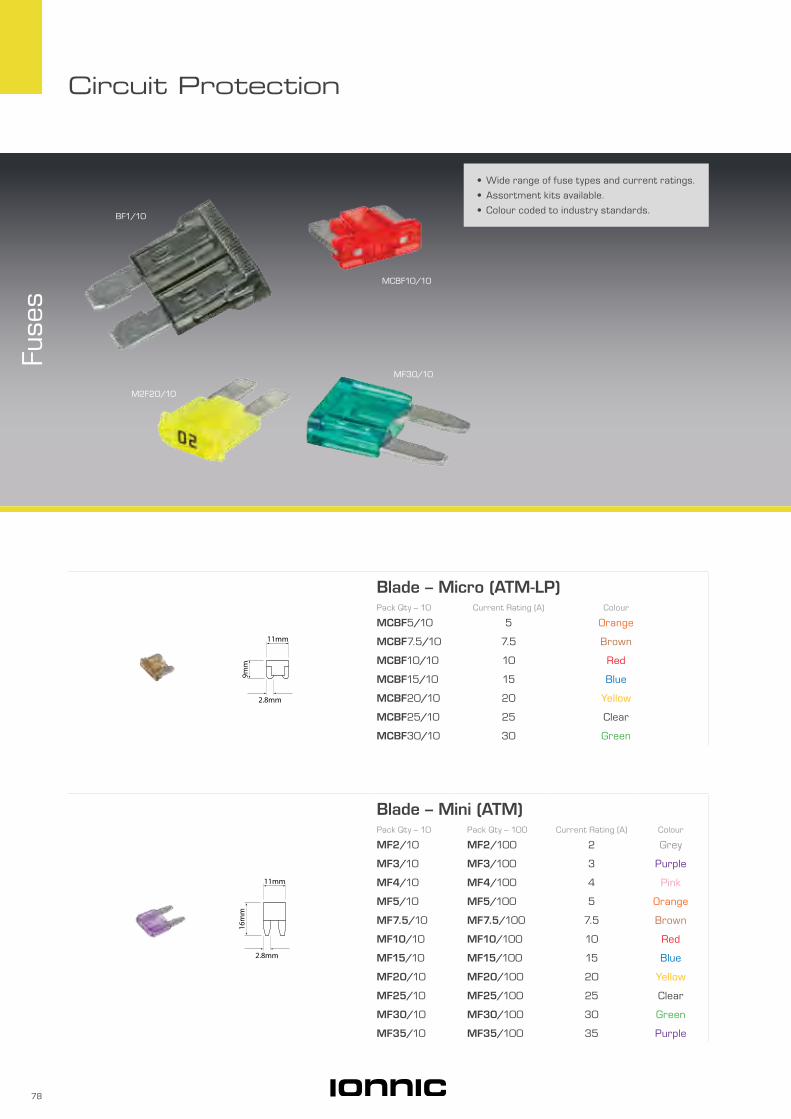
• Wide range of fuse types and current ratings.
• Assortment kits available.
• Colour coded to industry standards.
Fuse
s
16m
m
11mm
2.8mm
Blade – Mini (ATM)Pack Qty – 10 Pack Qty – 100 Current Rating (A) Colour
MF2/10 MF2/100 2 Grey
MF3/10 MF3/100 3 Purple
MF4/10 MF4/100 4 Pink
MF5/10 MF5/100 5 Orange
MF7.5/10 MF7.5/100 7.5 Brown
MF10/10 MF10/100 10 Red
MF15/10 MF15/100 15 Blue
MF20/10 MF20/100 20 Yellow
MF25/10 MF25/100 25 Clear
MF30/10 MF30/100 30 Green
MF35/10 MF35/100 35 Purple
9mm
11mm
2.8mm
Blade – Micro (ATM-LP)Pack Qty – 10 Current Rating (A) Colour
MCBF5/10 5 Orange
MCBF7.5/10 7.5 Brown
MCBF10/10 10 Red
MCBF15/10 15 Blue
MCBF20/10 20 Yellow
MCBF25/10 25 Clear
MCBF30/10 30 Green
MCBF10/10
MF30/10
M2F20/10
BF1/10
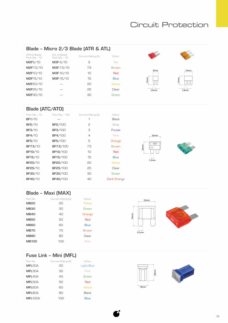
79
Circuit Protection
Fuse Link – Mini (MFL)
18mm
28m
m
Part No. Current Rating (A) Colour
MFL20A 20 Light-Blue
MFL30A 30 Pink
MFL40A 40 Green
MFL50A 50 Red
MFL60A 60 Yellow
MFL80A 80 Black
MFL100A 100 Blue
Blade (ATC/ATO)
20m
m
20mm
5.2mm
Pack Qty – 10 Pack Qty – 100 Current Rating (A) Colour
BF1/10 — 1 Black
BF2/10 BF2/100 2 Grey
BF3/10 BF3/100 3 Purple
BF4/10 BF4/100 4 Pink
BF5/10 BF5/100 5 Orange
BF7.5/10 BF7.5/100 7.5 Brown
BF10/10 BF10/100 10 Red
BF15/10 BF15/100 15 Blue
BF20/10 BF20/100 20 Yellow
BF25/10 BF25/100 25 Clear
BF30/10 BF30/100 30 Green
BF40/10 BF40/100 40 Dark Orange
Blade – Maxi (MAX)
34m
m
29mm
8.2mm
Part No. Current Rating (A) Colour
MB20 20 Yellow
MB30 30 Green
MB40 40 Orange
MB50 50 Red
MB60 60 Blue
MB70 70 Brown
MB80 80 Clear
MB100 100 Pink
Blade – Micro 2/3 Blade (ATR & ATL)
9mm
15m
m
2.8mm
14mm
15m
m
2.8mm
ATR (2 Blade) Pack Qty – 10
ATL (3 Blade) Pack Qty – 10 Current Rating (A) Colour
M2F5/10 M3F-5/10 5 Tan
M2F7.5/10 M3F-7.5/10 7.5 Brown
M2F10/10 M3F-10/10 10 Red
M2F15/10 M3F-15/10 15 Blue
M2F20/10 — 20 Yellow
M2F25/10 — 25 Clear
M2F30/10 — 30 Green

80
Circuit Protection
6mm
36mm
Glass (3AG)Pack Qty – 10 Current Rating (A)
3AG1/10 1
3AG3/10 3
3AG5/10 5
3AG7.5/10 7.5
3AG10/10 10
3AG15/10 15
3AG20/10 20
3AG25/10 25
3AG30/10 30
3AG35/10 35
6mm
25mm
Ceramic (6AC)Pack Qty – 10 Current Rating (A) Colour
6AC-5/10 5 Yellow
6AC-8/10 8 White
6AC-16/10 16 Red
6AC-25/10 25 Black
62mm
48mm
25m
m
Fuse Link – Flat (MFFL)Part No. Current Rating (A) Colour
MFFL20A 20 White
MFFL30A 30 Pink
MFFL40A 40 Green
MFFL50A 50 Red
MFFL60A 60 Yellow
MFFL80A 80 Black
MFFL100A 100 Blue
32mm
25m
m
45mm
25m
m
Fuse Link (FLM & FLF)Male Female Current Rating (A) Colour
FLM20A FLF20A 20 White
FLM30A FLF30A 30 Pink
FLM40A FLF40A 40 Green
FLM50A FLF50A 50 Red
FLM60A FLF60A 60 Yellow
FLM80A FLF80A 80 Black
FLM100A FLF100A 100 Blue

81
Circuit Protection
Fuse Assortment KitsPart No. Fuse Type Contents
BF-KIT Blade (ATC/ATO)
20 x 5A Fuses 20 x 10A Fuses 20 x 15A Fuses 20 x 20A Fuses 20 x 25A Fuses 20 x 30A Fuses
MF-KIT Blade – Mini (ATM)
10 x 5A Fuses 10 x 7.5A Fuses 20 x 10A Fuses 20 x 15A Fuses 20 x 20A Fuses 10 x 25A Fuses 10 x 30A Fuses
MCBF-KIT Blade – Micro (ATM-LP)
20 x 5A Fuses 20 x 10A Fuses 20 x 15A Fuses 20 x 20A Fuses 20 x 25A Fuses 20 x 30A Fuses
M2F-KITBlade (ATR) Fuse Link (FMM) Blade (ATL)
10 x 5A ATR Fuses 10 x 7.5A ATR Fuses 10 x 10A ATR Fuses 10 x 15A ATR Fuses 10 x 20A ATR Fuses 10 x 25A ATR Fuses 10 x 30A ATR Fuses
5 x 15A FMM Fuse Links 5 x 20A FMM Fuse Links 5 x 25A FMM Fuse Links 5 x 30A FMM Fuse Links 5 x 40A FMM Fuse Links
10 x 5A ATL 3 Blade Fuses 10 x 7.5A ATL 3 Blade Fuses 10 x 10A ATL 3 Blade Fuses 10 x 15A ATL 3 Blade Fuses
1 x Fuse Extractor Tool
CBF-KITBlade (ATC/ATO) Blade – Mini (ATM) Blade – Micro (ATM-LP)
10 x 10A ATC/ATO Fuses 10 x 15A ATC/ATO Fuses 10 x 20A ATC/ATO Fuses 10 x 25A ATC/ATO Fuses 10 x 30A ATC/ATO Fuses
20 x 10A ATM Fuses 20 x 15A ATM Fuses 20 x 20A ATM Fuses 20 x 25A ATM Fuses 20 x 30A ATM Fuses
20 x 10A ATM-LP Fuses 20 x 15A ATM-LP Fuses 20 x 20A ATM-LP Fuses 20 x 25A ATM-LP Fuses 20 x 30A ATM-LP Fuses
BF-KIT MF-KIT MCBF-KIT
CBF-KIT
M2F-KIT
82
Circuit Protection
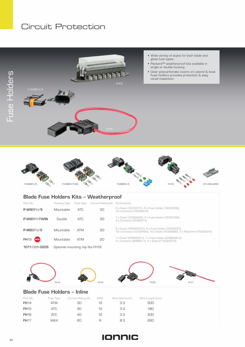
• Wide variety of styles for both blade and glass fuse types.
• Packard™ weatherproof kits available in single or double housing.
• Clear polycarbonate covers on Lateral & Axial Fuse Holders provides protection & easy visual inspection.
Fuse
Hol
ders
FH03
P-WSBFH/5
FH16
Blade Fuse Holders – InlinePart No. Fuse Type Current Rating (A) AWG Wire Size (mm2) Wire Length (mm)
FH14 ATM 30 12 3.3 300
FH15 ATC 30 12 3.3 180
FH16 ATC 40 12 3.3 300
FH17 MAX 60 8 8.3 260
FH15 FH17FH14 FH16
Blade Fuse Holders Kits – WeatherproofPart No. Housing Type Fuse Type Current Rating (A) Kit Contents
P-WSBFH/5 Mountable ATC 30 5 x Cover (12033731), 5 x Fuse Holder (12033769), 10 x Contacts (12066614)
P-WSBFH-TWIN Double ATC 30 1 x Cover (12059426), 2 x Fuse Holder (12033769), 4 x Contacts (12066614)
P-MSBFH/5 Mountable ATM 20 5 x Cover (15300027C), 5 x Fuse Holder (15300027), 10 x Contacts (12129493), 10 x Seals (15324982), 5 x Retainers (15300014)
FH19 Mountable ATM 20 1 x Cover (2066502-1), 1 x Fuse Holder (2066046-2), 4 x Contacts (968857-1), 4 x Seals (P-15324973)
1011-026-0205 Optional mounting clip fits FH19
P-WSBFH/5 P-WSBFH-TWIN 011-026-0205P-MSBFH/5 FH19

83
Circuit Protection
Blade Fuse Holders – AxialPart No. Seats Fuse Type Current Rating (A)
FH04 8 ATC 30
FH05 4 ATC 30
FH06 6 ATC 30
FH07 4 ATC 30 Supplied with contacts
12010105 1 ATC 30 For use with contact 12020321/100
Blade Fuse Holders – LateralPart No. Seats Fuse Type Current Rating (A)
FH01 4 ATC 30
FH02 6 ATC 30
FH03 8 ATC 30
FH01
37m
m
80mm
27m
m
64mm
Ø 5mm
FH02
100mm
37m
m
85mm
Ø 5mm
27m
m
FH03
120mm
37m
m
104mm
Ø 5mm
27m
m
Lateral Blade Fuse Holders – Side entry terminals
Interlocking slots allows holders to be
securely linked
FH07
49m
m25
mm
92mm
80mm
Ø 5mm
FH04
FH04 has 2 x M5 nuts moulded to case for
through-panel mounting
43m
m
115mm
32m
m
102mm
Ø 4mm
FH05
58m
m
65mm
54mm
Ø 5mm
26m
m
FH06
58m
m
86mm
Ø 5mm
72mm
26m
m
12010105
37m
m12
mm
23mm

84
Circuit Protection
Glass (3AG) Fuse Holders – InlinePart No. Current Rating (A) AWG Wire Size (mm2) Wire Length (mm)
FH210A-LD 20 14 4 160
FH210A 35 10 6 160
FH211 30 Water resistant, rubber
FH211FH210AFH210A-LD
Glass (3AG) Fuse Holders – Panel MountPart No. Current Rating (A)
FH207 15
FH208 16
Blade Fuse PanelPart No. Seats Contact Blade
Size (mm)Output Current Rating
Per Terminal (A)
FH108 8 x ATC 6.3 25
Blade fuses sold separately
85m
m
27m
m
111mm
31mm
20m
m
6.3mm
FH208FH207

85
Circuit Protection
• Provides an additional protected circuit without splicing or soldering.
• Easy & safe installation.
• Seamless crimp terminal on fly lead.
• Models suiting standard, mini or micro blade fuses.
Blade Fuse Tap
Current Rating : 10A per circuitCable Size : 4mm/1.84mm2
Blade Fuse TapPart No. Fuse Type
FH10 ATC
FH11 Mini (ATM)
FH18 Micro 2 (ATR)
FH10
29m
m
164mm
24mm
5mm0.5mm7mm
13mm
10m
m
FH11
30mm
2.8mm
11mm
10m
m
25m
m
7mm
0.7mm
160mm
FH18
FH11
34mm
3.8mm
10mm
8mm 24
mm
7mm
0.5mm
166mm
FH10

86
Circuit Protection
Pow
er D
istr
ibut
ion
Mod
ules • Mini & micro fuse and relay panels.
• Efficient power distribution in a rugged compact form for applications in marine, construction, agriculture, heavy trucking, specialty vehicles.
• Weather tight enclosure – IP66, when cover, cable seals, and cavity plugs are installed.
• Bussed (FH12) or non-bussed (FH20).
Max. Input Terminal Rating : FH12 M6 Studs 80AMax. Output Terminal Rating : 30AHousing : Black ThermoplasticIngress Protection : IP66*Operating Temperature : -40°C to 125°C
* IP66-IEC 60529 (Valid when properly installed with cover, sealed terminals, and cavity plugs.)
FH12
FH20
Power Distribution ModulesPart No. Seats Bussed
FH12 10 x ATM/233 Fuses, 5 x Micro Relays Yes
FH20 60 Position User Configurable No
93m
m
113m
m10
0mm
103m
m
86mm 53mm
M5
7mm
M675mm
Bussed
93m
m
113m
m10
0mm
103m
m
86mm 53mm
75mmM5
7mmFH12 FH20
Seats :• IONNIC Micro 280 Series Relays• Bussmann 233 Series Mini Blade
Circuit Breakers• Blade – Mini Fuses (ATM)
Seats :• 10 x Bussmann 233 Series Mini Blade
Circuit Breakers / Blade – Mini Fuses (ATM) • 5 x IONNIC Micro 280 Series Relays (PB2512RMC, PB2524RMC)
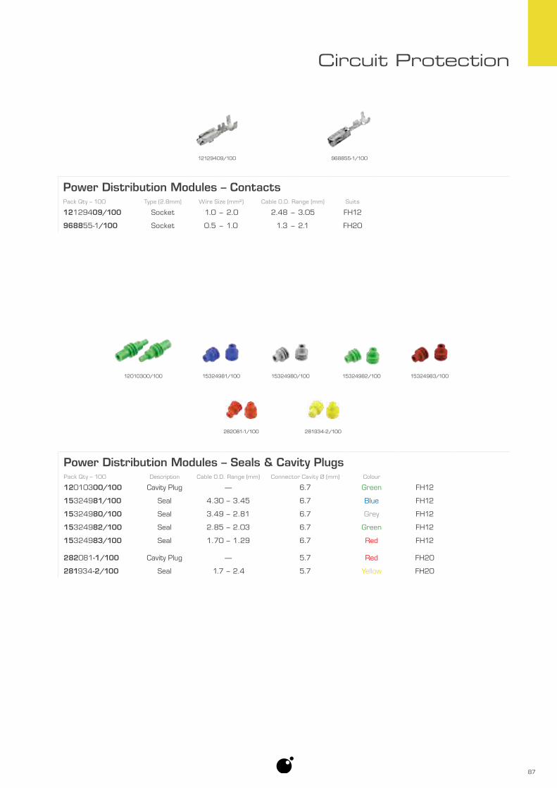
87
Circuit Protection
12129409/100 968855-1/100
Power Distribution Modules – ContactsPack Qty – 100 Type (2.8mm) Wire Size (mm²) Cable O.D. Range (mm) Suits
12129409/100 Socket 1.0 – 2.0 2.48 – 3.05 FH12
968855-1/100 Socket 0.5 – 1.0 1.3 – 2.1 FH20
Power Distribution Modules – Seals & Cavity PlugsPack Qty – 100 Description Cable O.D. Range (mm) Connector Cavity Ø (mm) Colour
12010300/100 Cavity Plug — 6.7 Green FH12
15324981/100 Seal 4.30 – 3.45 6.7 Blue FH12
15324980/100 Seal 3.49 – 2.81 6.7 Grey FH12
15324982/100 Seal 2.85 – 2.03 6.7 Green FH12
15324983/100 Seal 1.70 – 1.29 6.7 Red FH12
282081-1/100 Cavity Plug — 5.7 Red FH20
281934-2/100 Seal 1.7 – 2.4 5.7 Yellow FH20
12010300/100 15324981/100 15324980/100 15324982/100 15324983/100
282081-1/100 281934-2/100

88
Circuit Protection
• Designed to accept up to 2 x Micro 280 series relays, 4 x mini blade fuses/circuit breakers or a combination of both relays & fuses/circuit breakers.
• Compact size.
• Easy mounting.
• Eliminates excess wiring.
• High quality Packard™ terminals.
• Clear polycarbonate cover provides protection & easy visual inspection.
• Environmentally sealed – IP68.
Min
i Ele
ctrica
l Cen
tres
Current Rating : 120A max.Cover : PolycarbonateBody : ThermoplasticSeal : Silicon RubberContacts : Tinned BrassBracket : Zinc Plated SteelIngress Protection : IP66Operating Temperature : -40°C to 125°C
Mini Electrical Centre – Kits Kits contain: 1 x Mini Electrical Centre Body 1 x Mini Electrical Centre Cover 1 x Mounting Bracket 8 x Socket 0.8–1mm² (12077411) 8 x Seals 0.8–1mm² (15324982)
Part No. Cover
FH08 Low Profile
FH09 High Profile
FH09
FH08
FH09
Shown with various relays and fuses
Low Profile
High Profile
75m
m
67m
m
60mm
26m
m
36m
m
40mm
50m
m
42m
m
48mmØ 6mm
FH08
FH08

89
Circuit Protection
Mini Electrical Centres – Seals & Cavity PlugsPack Qty – 100 Description Cable O.D. Range (mm) Connector Cavity Ø (mm) Colour
15324982/100 Seal 2.85 – 2.03 6.7 Green
15324980/100 Seal 3.49 – 2.81 6.7 Grey
12010300/100 Cavity Plug — 6.7 Green
Packard™ products.
Mini Electrical Centres – ContactsPack Qty – 100 Type (2.8mm) Wire Size (mm²) Cable O.D. Range (mm)
12077411/100 Socket 0.5 – 1.25 2.03 – 3.12
12129493/100 Socket 2.0 – 3.0 2.45 – 3.80
Packard™ products.
15324982/100 15324980/100 12010300/100
12077411/100 12129493/100
Mini Electrical Centres are compatible with :• IONNIC Micro 280 Series Relays.
• Bussmann 233 Series Mini Blade Circuit Breakers page 77.
• Blade – Mini Fuses (ATM) page 78.
High Profile model required if using relays or circuit breakers.

90
Circuit Protection
• Designed for high current applications.
• Suitable for extreme moisture and high vibration environments.
• Silicone seal and removable cover offer a weather-tight enclosure for fuses.
• Multiple units can be connected together using a buss bar.
Mod
ular
MFL
Fus
e H
olde
r
Body : ThermoplasticSeal : Silicon RubberTerminal : Tinned CopperStuds : Plated SteelIngress Protection : IP66 (excluding studs)Operating Temperature : -40°C to 85°CApprovals : SAE 31171 (ignition protection)
Holds up to two Fuse Links
Minis (MFL) Page 79
Multiple units can be connected together
using a buss bar
Modular MFL Fuse HolderPart No. Seats Fuse Type Current Rating (A)
FH22 2 Fuse Link – Mini (MFL) 20 – 60 (each)
3771BUS-2 Buss bar – 2 position
3771BUS-3 Buss bar – 3 position
FH22 3771BUS-2 3771BUS-3
Ø 6mm
95mm
43m
m40
mm
Internet

Internet
• Keep up to date with the latest product releases.
• Compare products.• Download catalogues or technical
information.
Internetionnic.com
Lighting | Safety | Electrical
ionnic.com

92
Circuit Protection
• Power distribution protection.
• High current ratings.
• Compact size.
• Secure bolt-in connection.
• AMG series colour-coded to current rating.
• AMI & ANL series allow easy fuse inspection.
• Ideal for use in mining and emergency service vehicles, battery chargers and inverters.
Bol
t-in
Fus
es
Voltage Rating : AMI, AMG 32VANL 80V
Terminal : AMI Tin-plated BrassAMG CopperANL Silver-plated Copper
Operating Temperature : -40°C to 125°C
AMI80
AMG125
ANL500
AMI Series30A 40A 50A 60A 70A 80A 100A 125A 150A 175A 200A
AMI30 AMI40 AMI50 AMI60 AMI70 AMI80 AMI100 AMI125 AMI150 AMI175 AMI200
AMI100
AMI50
30mm Ø 5mm
12m
m
40mm
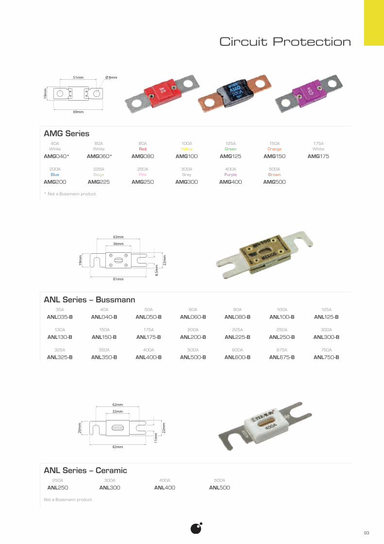
93
Circuit Protection
AMG Series40A 60A 80A 100A 125A 150A 175A
White White Red Yellow Green Orange White
AMG040* AMG060* AMG080 AMG100 AMG125 AMG150 AMG175
200A 225A 250A 300A 400A 500ABlue Beige Pink Grey Purple Brown
AMG200 AMG225 AMG250 AMG300 AMG400 AMG500
* Not a Bussmann product.
51mm
69mm
19m
m
Ø 8mm
8.5m
m
63mm
36mm
19m
m
22m
m
81mm
ANL Series – Bussmann35A 40A 50A 60A 80A 100A 125A
ANL035-B ANL040-B ANL050-B ANL060-B ANL080-B ANL100-B ANL125-B
130A 150A 175A 200A 225A 250A 300A
ANL130-B ANL150-B ANL175-B ANL200-B ANL225-B ANL250-B ANL300-B
325A 350A 400A 500A 600A 675A 750A
ANL325-B ANL350-B ANL400-B ANL500-B ANL600-B ANL675-B ANL750-B
ANL Series – Ceramic250A 300A 400A 500A
ANL250 ANL300 ANL400 ANL500
Not a Bussmann product.
11m
m
62mm
32mm
82mm
20m
m
22m
m

94
Circuit Protection
• Used for primary branch fusing.
• Models to suit AMI, AMG & ANL fuses.
• Ideal for mining, agriculture, bus, truck, marine and specialty vehicle applications.
Bol
t-in
Fus
e H
olde
rs
Base : ThermoplasticCover : AMGFH1 TPE Rubber
LMG EPDM RubberTerminal : Plated SteelOperating Temperature : -40°C to 85°C
LMG3-1-001
ANLFH1
AMGFH1
AMGFH2
Inline/Panel MountPart No. Fuse Type
AMGFH2 AMG
Fuses not included.
51mm
40mm
123mm 24m
m
Ø 8mm
Shown with fuse
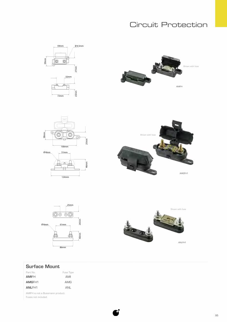
95
Circuit Protection
Surface MountPart No. Fuse Type
AMIFH AMI
AMGFH1 AMG
ANLFH1 ANL
AMIFH is not a Bussmann product.
Fuses not included.
AMIFH
ANLFH1
AMGFH1
25m
m
38m
m
100mm
51mm
46m
m
124mm
Ø 8mm
32mm
Ø 4.5mm59mm39
mm
27m
m23
mm
72mm
25mm
24m
m40
mm
61mm
86mm
Ø 8mm
Shown with fuse
Shown with fuse
Shown with fuse
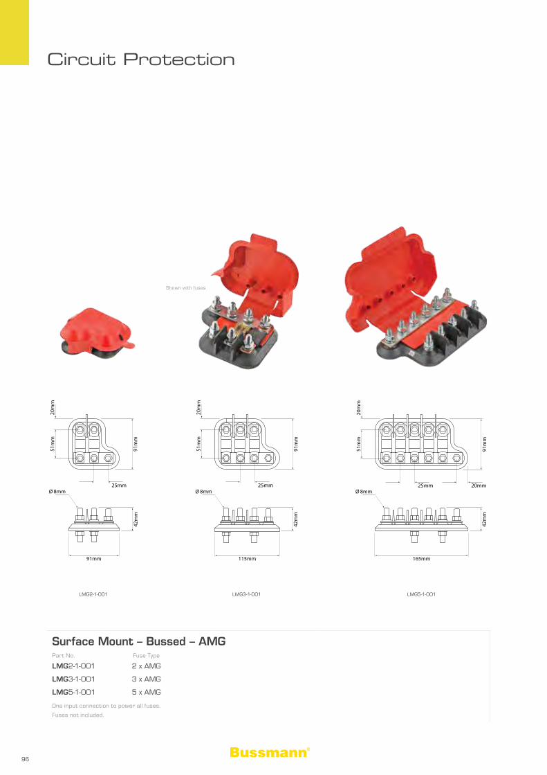
96
Circuit Protection
Surface Mount – Bussed – AMGPart No. Fuse Type
LMG2-1-001 2 x AMG
LMG3-1-001 3 x AMG
LMG5-1-001 5 x AMG
One input connection to power all fuses.
Fuses not included.
LMG2-1-001 LMG3-1-001 LMG5-1-001
Shown with fuses
20m
m
91m
m
51m
m
25mm
42m
m
91mm
Ø 8mm
20m
m
91m
m
51m
m
25mm
42m
m
115mm
Ø 8mm
20m
m
91m
m
51m
m
42m
m
165mm
Ø 8mm25mm 20mm
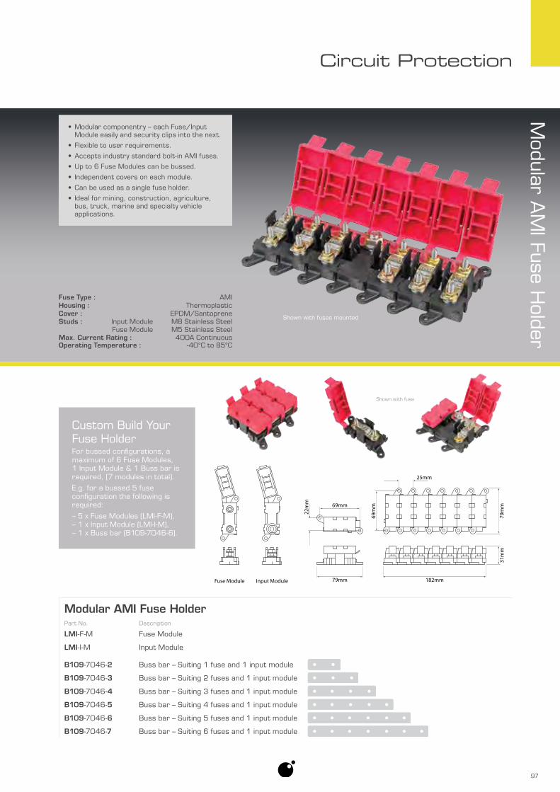
97
Circuit Protection
Modular A
MI Fuse H
older
Modular AMI Fuse HolderPart No. Description
LMI-F-M Fuse Module
LMI-I-M Input Module
B109-7046-2 Buss bar – Suiting 1 fuse and 1 input module
B109-7046-3 Buss bar – Suiting 2 fuses and 1 input module
B109-7046-4 Buss bar – Suiting 3 fuses and 1 input module
B109-7046-5 Buss bar – Suiting 4 fuses and 1 input module
B109-7046-6 Buss bar – Suiting 5 fuses and 1 input module
B109-7046-7 Buss bar – Suiting 6 fuses and 1 input module
Custom Build Your Fuse HolderFor bussed configurations, a maximum of 6 Fuse Modules, 1 Input Module & 1 Buss bar is required, (7 modules in total).
E.g. for a bussed 5 fuse configuration the following is required:
– 5 x Fuse Modules (LMI-F-M), – 1 x Input Module (LMI-I-M), – 1 x Buss bar (B109-7046-6).
• Modular componentry – each Fuse/Input Module easily and security clips into the next.
• Flexible to user requirements.
• Accepts industry standard bolt-in AMI fuses.
• Up to 6 Fuse Modules can be bussed.
• Independent covers on each module.
• Can be used as a single fuse holder.
• Ideal for mining, construction, agriculture, bus, truck, marine and specialty vehicle applications.
Fuse Type : AMIHousing : ThermoplasticCover : EPDM/SantopreneStuds : Input Module M8 Stainless Steel
Fuse Module M5 Stainless SteelMax. Current Rating : 400A ContinuousOperating Temperature : -40°C to 85°C
31m
m
25mm
79m
m
69m
m
182mm79mm
69mm
22m
m
Fuse Module Input Module
Shown with fuses mounted
Shown with fuse

98
Circuit Protection
PID41
• Plug & play connection.
• Multiple configurations.
• Industry standard connector.
• Pin connection diagrams are clearly labeled on housing.
Plu
g-in
Dio
des
Housing : Thermoplastic PolymerConnector : PolyamideTerminal Size : 6.3mmMax. Average Rectified Current : 3AOperating Temperature : -65°C to 150°C
Plug-in DiodesPart No. Pin Connection Max. Reverse Voltage Matching Housing
PID6A 600 QK2BSL/10
PID41 400 QK4BSL/10
PID42 400 QK4BSL/10
PID42 49m
m
22mm
20m
m
25mm
49m
m
22mm
20m
m
25mm
PID42
PID6A
10mm
22m
m
13mm
44m
m
PID6A

99
Circuit Protection
Housing : PolymerCM3504 Metal, electrically isolated
DiodesPart No. Nominal Zener
VoltageMax. Reverse
VoltageMax. Forward
Current (A)Max. RMS
Input VoltageMax. DC
Blocking VoltagePack Qty
ZSD6A4/10* 120 — 6 200 — 10
IN4004/10 — 400 1 280 400 10
IN5408/10 — 1000 3 700 1000 10
CM3504 — 400 35 280 400 1
* Zener diode.
ZSD6A4/10
CM3504
• High current capability.
• Low leakage current.
• Flame retardant epoxy.
• High surge capability.
• CM3504 features epoxy filled metal housing.
IN4004/10 IN5408/10
Band denotes cathode end
ZSD6A4/10
28mm
12m
m
11m
m
Ø 5mm
6.3mm
28m
m
CM3504
Epoxy filled, metal heatsink
housing
Diodes


CableThin Wall Cable 102
Single Cable 107
Battery Cable 110
Tinned 112
Sheathed 114
Twin Core Figure 8 Cable 115
Speaker Cable 115
Coaxial RG58 Cable 115
Multi Core Cable – Flexible Control 116
CAN Data Cable 116
Special Cable 116

102
Cable
Thin Wall Cable – No TraceColour 0.5mm2 1.0mm2 2.0mm2 2.5mm2 4.5mm² 6mm²
TW050-BLK-500 TW100-BLK-500 TW200-BLK-500 NA TW450-BLK-250 TW600-BLK-100Black
TW050-BLU-500 TW100-BLU-500 TW200-BLU-500 NA TW450-BLU-250 NABlue
TW050-BRN-500 TW100-BRN-500 TW200-BRN-500 NA NA NABrown
TW050-D-GRN-500 TW100-D-GRN-500 NA NA NA NADk Grn
TW050-GRN-500 TW100-GRN-500 TW200-GRN-500 NA NA NAGreen
TW050-GRY-500 TW100-GRY-500 TW200-GRY-500 NA NA NAGrey
TW050-ONG-500 TW100-ONG-500 TW200-ONG-500 NA NA NAOrange
TW050-PNK-500 TW100-PNK-500 TW200-PNK-500 NA NA NAPink
TW050-PUR-500 TW100-PUR-500 TW200-PUR-500 NA NA NAPurple
TW050-RED-500 TW100-RED-500 TW200-RED-500 TW250-RED-250 TW450-RED-250 NARed
White TW050-WHT-500 TW100-WHT-500 TW200-WHT-500 NA NA NA
TW050-YEL-500 TW100-YEL-500 TW200-YEL-500 NA NA NAYellow
Items marked as NA can be supplied for an additional fee. Lead times apply.
Thin Wall CableTW050 TW100 TW200 TW250 TW450 TW600
Nominal Area (mm2) : 0.5 1.0 2.0 2.5 4.5 6.0Strand Count : 16 32 28 50 65 85Strand Diameter (mm) : 0.2 0.2 0.3 0.25 0.3 0.3Nominal O.D. (mm) : 1.5 2.0 2.6 2.85 3.9 4.2Roll Length (m) : 500 500 500 250 250 100
Common SpecsMax. Operating Temperature : 105°CMax. Voltage : 600
Nominal O.D.
InsulationThickness
Nominal Area(mm2)
Part Number Prefix
Nominal Area
Base Colour Trace Colour
Roll Length (m)
TW100-BRN/PUR-500
Thin Wall Cable – Black Trace VariationsColour 0.5mm2 1.0mm2 2.0mm2
Blue Trace NA TW100-BLK/BLU-500 NA
Brown Trace TW050-BLK/BRN-500 NA NA
Dark Green Trace NA TW100-BLK/D-GRN-500 TW200-BLK/D-GRN-500
Green Trace NA NA NA
Grey Trace NA TW100-BLK/GRY-500 NA
Orange Trace NA NA NA
Pink Trace TW050-BLK/PNK-500 NA NA
Purple Trace NA NA NA
Red Trace NA TW100-BLK/RED-500 TW200-BLK/RED-500
White Trace TW050-BLK/WHT-500 TW100-BLK/WHT-500 TW200-BLK/WHT-500
Yellow Trace NA TW100-BLK/YEL-500 NA
Items marked as NA can be supplied for an additional fee. Lead times apply.
Lead Free PVC Insulation on all Thin Wall Cable

103
Cable
Thin Wall Cable – Blue Trace VariationsColour 0.5mm2 1.0mm2 2.0mm2
Black Trace TW050-BLU/BLK-500 TW100-BLU/BLK-500 TW200-BLU/BLK-500
Brown Trace NA TW100-BLU/BRN-500 NA
Dark Green Trace TW050-BLU/D-GRN-500 TW100-BLU/D-GRN-500 TW200-BLU/D-GRN-500
Grey Trace TW050-BLU/GRY-500 TW100-BLU/GRY-500 NA
Orange Trace NA TW100-BLU/ONG-500 NA
Pink Trace NA NA NA
Red Trace TW050-BLU/RED-500 TW100-BLU/RED-500 NA
White Trace TW050-BLU/WHT-500 TW100-BLU/WHT-500 TW200-BLU/WHT-500
Yellow Trace TW050-BLU/YEL-500 TW100-BLU/YEL-500 NA
Items marked as NA can be supplied for an additional fee. Lead times apply.
Thin Wall Cable – Brown Trace VariationsColour 0.5mm2 1.0mm2 2.0mm2
Black Trace NA TW100-BRN/BLK-500 NA
Blue Trace NA TW100-BRN/BLU-500 TW200-BRN/BLU-500
Dark Green Trace NA TW100-BRN/D-GRN-500 NA
Grey Trace NA TW100-BRN/GRY-500 TW200-BRN/GRY-500
Orange Trace NA TW100-BRN/ONG-500 TW200-BRN/ONG-500
Pink Trace NA TW100-BRN/PNK-500 TW200-BRN/PNK-500
Purple Trace NA TW100-BRN/PUR-500 TW200-BRN/PUR-500
Red Trace NA TW100-BRN/RED-500 NA
White Trace TW050-BRN/WHT-500 TW100-BRN/WHT-500 TW200-BRN/WHT-500
Yellow Trace TW050-BRN/YEL-500 TW100-BRN/YEL-500 TW200-BRN/YEL-500
Items marked as NA can be supplied for an additional fee. Lead times apply.
Thin Wall Cable – Dark Green Trace VariationsColour 0.5mm2 1.0mm2 2.0mm2
Black Trace NA TW100-D-GRN/BLK-500 TW200-D-GRN/BLK-500
Blue Trace NA TW100-D-GRN/BLU-500 NA
Brown Trace NA TW100-D-GRN/BRN-500 TW200-D-GRN/BRN-500
Grey Trace NA TW100-D-GRN/GRY-500 NA
Orange Trace NA TW100-D-GRN/ONG-500 NA
Pink Trace NA TW100-D-GRN/PNK-500 NA
Purple Trace NA TW100-D-GRN/PUR-500 TW200-D-GRN/PUR-500
Red Trace TW050-D-GRN/RED-500 TW100-D-GRN/RED-500 TW200-D-GRN/RED-500
White Trace TW050-D-GRN/WHT-500 TW100-D-GRN/WHT-500 TW200-D-GRN/WHT-500
Yellow Trace NA TW100-D-GRN/YEL-500 NA
Items marked as NA can be supplied for an additional fee. Lead times apply.

104
Cable
Thin Wall Cable – Green Trace VariationsColour 0.5mm2 1.0mm2 2.0mm2
Black Trace TW050-GRN/BLK-500 TW100-GRN/BLK-500 NA
Brown Trace NA NA NA
Dark Green Trace NA NA NA
Purple Trace NA NA NA
Red Trace NA NA NA
Yellow Trace TW050-GRN/YEL-500 NA NA
Items marked as NA can be supplied for an additional fee. Lead times apply.
Thin Wall Cable – Grey Trace VariationsColour 0.5mm2 1.0mm2 2.0mm2
Black Trace TW050-GRY/BLK-500 TW100-GRY/BLK-500 NA
Blue Trace NA TW100-GRY/BLU-500 NA
Purple Trace NA TW100-GRY/PUR-500 NA
Red Trace NA TW100-GRY/RED-500 NA
White Trace NA TW100-GRY/WHT-500 NA
Yellow Trace NA NA NA
Items marked as NA can be supplied for an additional fee. Lead times apply.
Thin Wall Cable – Orange Trace VariationsColour 0.5mm2 1.0mm2 2.0mm2
Black Trace NA TW100-ONG/BLK-500 NA
Blue Trace TW050-ONG/BLU-500 TW100-ONG/BLU-500 NA
Brown Trace NA TW100-ONG/BRN-500 NA
Dark Green Trace NA TW100-ONG/D-GRN-500 NA
Purple Trace NA TW100-ONG/PUR-500 NA
Red Trace TW050-ONG/RED-500 NA NA
White Trace NA TW100-ONG/WHT-500 NA
Yellow Trace NA NA NA
Items marked as NA can be supplied for an additional fee. Lead times apply.

105
Cable
Thin Wall Cable – Pink Trace VariationsColour 0.5mm2 1.0mm2 2.0mm2
Black Trace TW050-PNK/BLK-500 TW100-PNK/BLK-500 NA
Blue Trace NA TW100-PNK/BLU-500 NA
Brown Trace NA TW100-PNK/BRN-500 NA
Dark Green Trace NA TW100-PNK/D-GRN-500 NA
Grey Trace NA TW100-PNK/GRY-500 NA
White Trace NA TW100-PNK/WHT-500 TW200-PNK/WHT-500
Yellow Trace NA TW100-PNK/YEL-500 NA
Items marked as NA can be supplied for an additional fee. Lead times apply.
Thin Wall Cable – Purple Trace VariationsColour 0.5mm2 1.0mm2 2.0mm2
Black Trace NA TW100-PUR/BLK-500 NA
Blue Trace NA TW100-PUR/BLU-500 NA
Dark Green Trace NA TW100-PUR/D-GRN-500 NA
Grey Trace NA TW100-PUR/GRY-500 NA
Orange Trace NA TW100-PUR/ONG-500 NA
Pink Trace NA TW100-PUR/PNK-500 NA
Red Trace TW050-PUR/RED-500 TW100-PUR/RED-500 NA
White Trace TW050-PUR/WHT-500 TW100-PUR/WHT-500 NA
Yellow Trace NA TW100-PUR/YEL-500 NA
Items marked as NA can be supplied for an additional fee. Lead times apply.
Thin Wall Cable – Red Trace VariationsColour 0.5mm2 1.0mm2 2.0mm2
Black Trace TW050-RED/BLK-500 TW100-RED/BLK-500 TW200-RED/BLK-500
Blue Trace NA TW100-RED/BLU-500 TW200-RED/BLU-500
Brown Trace TW050-RED/BRN-500 TW100-RED/BRN-500 NA
Dark Green Trace TW050-RED/D-GRN-500 TW100-RED/D-GRN-500 TW200-RED/D-GRN-500
Grey Trace NA TW100-RED/GRY-500 TW200-RED/GRY-500
Orange Trace NA TW100-RED/ONG-500 NA
Purple Trace TW050-RED/PUR-500 TW100-RED/PUR-500 NA
White Trace TW050-RED/WHT-500 TW100-RED/WHT-500 TW200-RED/WHT-500
Yellow Trace TW050-RED/YEL-500 TW100-RED/YEL-500 TW200-RED/YEL-500
Items marked as NA can be supplied for an additional fee. Lead times apply.

106
Cable
Thin Wall Cable – White Trace VariationsColour 0.5mm2 1.0mm2 2.0mm2
Black Trace TW050-WHT/BLK-500 TW100-WHT/BLK-500 TW200-WHT/BLK-500
Blue Trace TW050-WHT/BLU-500 TW100-WHT/BLU-500 NA
Brown Trace TW050-WHT/BRN-500 TW100-WHT/BRN-500 NA
Dark Green Trace TW050-WHT/D-GRN-500 TW100-WHT/D-GRN-500 TW200-WHT/D-GRN-500
Grey Trace TW050-WHT/GRY-500 TW100-WHT/GRY-500 TW200-WHT/GRY-500
Orange Trace NA TW100-WHT/ONG-500 TW200-WHT/ONG-500
Pink Trace NA TW100-WHT/PNK-500 NA
Purple Trace NA TW100-WHT/PUR-500 TW200-WHT/PUR-500
Red Trace TW050-WHT/RED-500 TW100-WHT/RED-500 TW200-WHT/RED-500
Yellow Trace TW050-WHT/YEL-500 TW100-WHT/YEL-500 TW200-WHT/YEL-500
Items marked as NA can be supplied for an additional fee. Lead times apply.
Thin Wall Cable – Yellow Trace VariationsColour 0.5mm2 1.0mm2 2.0mm2
Black Trace TW050-YEL/BLK-500 TW100-YEL/BLK-500 TW200-YEL/BLK-500
Blue Trace NA TW100-YEL/BLU-500 NA
Brown Trace NA TW100-YEL/BRN-500 NA
Dark Green Trace TW050-YEL/D-GRN-500 TW100-YEL/D-GRN-500 TW200-YEL/D-GRN-500
Grey Trace NA NA NA
Orange Trace NA TW100-YEL/ONG-500 NA
Pink Trace NA TW100-YEL/PNK-500 NA
Red Trace TW050-YEL/RED-500 TW100-YEL/RED-500 TW200-YEL/RED-500
White Trace TW050-YEL/WHT-500 TW100-YEL/WHT-500 TW200-YEL/WHT-500
Items marked as NA can be supplied for an additional fee. Lead times apply.

107
Cable
T1-4-GRN/RED-100Part Number Prefix
Industry Equivalent mmRoll Length (m)
Base Colour Trace Colour
Single Cable Trace VariationsT1-3 T1-4 T1-5 T1-6
Industry Equivalent mm : 3 4 5 6Nominal Area (mm2) : 1.13 1.84 2.9 4.59Strand Count : 14 23 36 57Strand Diameter (mm) : 0.32 0.32 0.32 0.32Nominal O.D. (mm) : 2.2 2.3 3.0 4.0
Nominal O.D.
InsulationThickness
Nominal Area(mm2)
Single Cable – No TraceIndustry Equivalent mm*
Colour Roll Length 3mm 4mm 5mm 6mm
Black30m T1-3-BLK-30 T1-4-BLK-30 T1-5-BLK-30 T1-6-BLK-30
100m T1-3-BLK-100 T1-4-BLK-100 T1-5-BLK-100 T1-6-BLK-100
Blue30m T1-3-BLU-30 T1-4-BLU-30 T1-5-BLU-30 T1-6-BLU-30
100m T1-3-BLU-100 T1-4-BLU-100 T1-5-BLU-100 —
Green30m T1-3-GRN-30 T1-4-GRN-30 T1-5-GRN-30 T1-6-GRN-30
100m T1-3-GRN-100 T1-4-GRN-100 — T1-6-GRN-100
Red30m T1-3-RED-30 T1-4-RED-30 T1-5-RED-30 T1-6-RED-30
100m T1-3-RED-100 T1-4-RED-100 T1-5-RED-100 T1-6-RED-100
Yellow30m T1-3-YEL-30 T1-4-YEL-30 T1-5-YEL-30 T1-6-YEL-30
100m T1-3-YEL-100 T1-4-YEL-100 — T1-6-YEL-100
White30m T1-3-WHT-30 T1-4-WHT-30 T1-5-WHT-30 T1-6-WHT-30
100m T1-3-WHT-100 T1-4-WHT-100 T1-5-WHT-100 T1-6-WHT-100
Brown30m T1-3-BRN-30 T1-4-BRN-30 T1-5-BRN-30 —
100m — T1-4-BRN-100 T1-5-BRN-100 —
Grey30m T1-3-GRY-30 T1-4-GRY-30 — —
100m T1-3-GRY-100 T1-4-GRY-100 — —
Orange30m T1-3-ONG-30 T1-4-ONG-30 — T1-6-ONG-30
100m T1-3-ONG-100 T1-4-ONG-100 — —
Pink30m T1-3-PNK-30 T1-4-PNK-30 T1-5-PNK-30 —
100m T1-3-PNK-100 T1-4-PNK-100 — —
Purple30m T1-3-PUR-30 T1-4-PUR-30 — —
100m T1-3-PUR-100 T1-4-PUR-100 — —
* Industry term for identifying cable size not conductor size (Nominal Area).

108
Cable
Single Cable – Green Trace VariationsIndustry Equivalent mm*
Colour Roll Length 3mm 4mm
Red Trace30m T1-3-GRN/RED-30 T1-4-GRN/RED-30
100m — T1-4-GRN/RED-100
White Trace30m T1-3-GRN/WHT-30 T1-4-GRN/WHT-30
100m — T1-4-GRN/WHT-100
Yellow Trace30m T1-3-GRN/YEL-30 —
100m — T1-4-GRN/YEL-100
Blue Trace 100m — T1-4-GRN/BLU-100
Black Trace30m T1-3-GRN/BLK-30 —
100m — T1-4-GRN/BLK-100
Brown Trace 100m T1-3-GRN/BRN-100 —
* Industry term for identifying cable size not conductor size (Nominal Area).
Single Cable – Red Trace VariationsIndustry Equivalent mm*
Colour Roll Length 3mm 4mm
Green Trace30m T1-3-RED/GRN-30 —
100m — T1-4-RED/GRN-100
White Trace30m T1-3-RED/WHT-30 T1-4-RED/WHT-30
100m — T1-4-RED/WHT-100
Yellow Trace30m T1-3-RED/YEL-30 —
100m — T1-4-RED/YEL-100
Blue Trace30m T1-3-RED/BLU-30 —
100m T1-3-RED/BLU-100 T1-4-RED/BLU-100
Black Trace30m T1-3-RED/BLK-30 —
100m — T1-4-RED/BLK-100
* Industry term for identifying cable size not conductor size (Nominal Area).
Single Cable – Black Trace VariationsIndustry Equivalent mm*
Colour Roll Length 3mm 4mm
Green Trace 30m T1-3-BLK/GRN-30 —
Red Trace30m T1-3-BLK/RED-30 —
100m T1-3-BLK/RED-100 —
White Trace 30m T1-3-BLK/WHT-30 T1-4-BLK/WHT-30
Yellow Trace30m T1-3-BLK/YEL-30 —
100m T1-3-BLK/YEL-100 —
* Industry term for identifying cable size not conductor size (Nominal Area).

109
Cable
Single Cable – Yellow Trace VariationsIndustry Equivalent mm*
Colour Roll Length 3mm 4mm
Green Trace 100m T1-3-YEL/GRN-100 —
Red Trace 100m T1-3-YEL/RED-100 —
Blue Trace30m T1-3-YEL/BLU-30 T1-4-YEL/BLU-30
100m T1-3-YEL/BLU-100 —
* Industry term for identifying cable size not conductor size (Nominal Area).
Single Cable – Brown Trace VariationsIndustry Equivalent mm*
Colour Roll Length 3mm 4mm
White Trace 30m T1-3-BRN/WHT-30 T1-4-BRN/WHT-30
* Industry term for identifying cable size not conductor size (Nominal Area).
Single Cable – White Trace VariationsIndustry Equivalent mm*
Colour Roll Length 3mm 4mm
Red Trace 100m — T1-4-WHT/RED-100
Blue Trace 30m T1-3-WHT/BLU-30 —
Black Trace30m — T1-4-WHT/BLK-30
100m — T1-4-WHT/BLK-100
Brown Trace30m T1-3-WHT/BRN-30 T1-4-WHT/BRN-30
100m — T1-4-WHT/BRN-100
Orange Trace30m T1-3-WHT/ONG-30 —
100m T1-3-WHT/ONG-100 —
* Industry term for identifying cable size not conductor size (Nominal Area).
Single Cable – Blue Trace VariationsIndustry Equivalent mm*
Colour Roll Length 3mm 4mm
Red Trace30m T1-3-BLU/RED-30 —
100m T1-3-BLU/RED-100 T1-4-BLU/RED-100
White Trace30m T1-3-BLU/WHT-30 —
100m T1-3-BLU/WHT-100 —
Yellow Trace 100m T1-3-BLU/YEL-100 T1-4-BLU/YEL-100
* Industry term for identifying cable size not conductor size (Nominal Area).

110
Cable
Battery CablePart No Colour Roll Length
(m)Nom. Area
(mm2)Nom. O.D.
(mm) Conductor Max. Operating Temperature (°C)
Minimum Bending Radius (mm)
T1-7-BLK-30 Black 30 7.92 5.4 112 / 0.3 90 13
T1-7-BLK-100 Black 100 7.92 5.4 112 / 0.3 90 13
T1-7-RED-30 Red 30 7.92 5.4 112 / 0.3 90 13
T1-7-RED-100 Red 100 7.92 5.4 112 / 0.3 90 13
T1-17-BLK-30 Black 30 16 6.6 224 / 0.3 125 16
T1-17-BLK-100 Black 100 16 6.6 224 / 0.3 125 16
T1-17-RED-30 Red 30 16 6.6 224 / 0.3 125 16
T1-17-RED-100 Red 100 16 6.6 224 / 0.3 125 16
T1-36-BLK-30 Black 30 25 8.3 350 / 0.3 125 21
T1-36-RED-30 Red 30 25 8.3 350 / 0.3 125 21
T1-8-BLK-30 Black 30 35 9.7 490 / 0.3 125 24
T1-8-RED-30 Red 30 35 9.7 490 / 0.3 125 24
T1-117-BLK-30 Black 30 50 11.3 770 / 0.3 125 28
T1-117-RED-30 Red 30 50 11.3 770 / 0.3 125 28
T1-116-BLK-30 Black 30 70 13.1 980 / 0.3 125 33
T1-116-RED-30 Red 30 70 13.1 980 / 0.3 125 33
Double Insulated – Battery Cable TinnedPart No Colour Roll Length
(m)Nom. Area
(mm2)Max. O.D.
(mm) Conductor
TC16BLK-50 Black 50 16 11.1 123 / 0.41
TC25BLK-50 Black 50 25 13.4 190 / 0.41
TC35BLK-50 Black 50 35 14.6 268 / 0.41
TC50BLK-50 Black 50 50 16.4 384 / 0.41
TC70BLK-50 Black 50 70 18.3 545 / 0.41
TC95BLK-50 Black 50 95 20.8 724 / 0.41
TC120BLK-50 Black 50 120 22.4 926 / 0.41
Single Core Double Insulated Rubber 1.9/3.3kV 1100C.
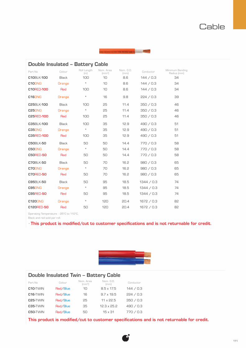
111
Cable
Double Insulated Twin – Battery CablePart No Colour Nom. Area
(mm2)Nom. O.D.
(mm) Conductor
C10-TWIN Red/Blue 10 8.5 x 17.5 144 / 0.3
C16-TWIN Red/Blue 16 9.7 x 19.5 224 / 0.3
C25-TWIN Red/Blue 25 11 x 22.5 350 / 0.3
C35-TWIN Red/Blue 35 12.3 x 25.2 490 / 0.3
C50-TWIN Red/Blue 50 15 x 31 770 / 0.3
This product is modified/cut to customer specifications and is not returnable for credit.
Double Insulated – Battery CablePart No Colour Roll Length
(m)Nom. Area
(mm2)Nom. O.D.
(mm) Conductor Minimum Bending Radius (mm)
C10BLK-100 Black 100 10 8.6 144 / 0.3 34
C10ONG Orange * 10 8.6 144 / 0.3 34
C10RED-100 Red 100 10 8.6 144 / 0.3 34
C16ONG Orange * 16 9.8 224 / 0.3 39
C25BLK-100 Black 100 25 11.4 350 / 0.3 46
C25ONG Orange * 25 11.4 350 / 0.3 46
C25RED-100 Red 100 25 11.4 350 / 0.3 46
C35BLK-100 Black 100 35 12.9 490 / 0.3 51
C35ONG Orange * 35 12.9 490 / 0.3 51
C35RED-100 Red 100 35 12.9 490 / 0.3 51
C50BLK-50 Black 50 50 14.4 770 / 0.3 58
C50ONG Orange * 50 14.4 770 / 0.3 58
C50RED-50 Red 50 50 14.4 770 / 0.3 58
C70BLK-50 Black 50 70 16.2 980 / 0.3 65
C70ONG Orange * 70 16.2 980 / 0.3 65
C70RED-50 Red 50 70 16.2 980 / 0.3 65
C95BLK-50 Black 50 95 18.5 1344 / 0.3 74
C95ONG Orange * 95 18.5 1344 / 0.3 74
C95RED-50 Red 50 95 18.5 1344 / 0.3 74
C120ONG Orange * 120 20.4 1672 / 0.3 82
C120RED-50 Red 50 120 20.4 1672 / 0.3 82
Operating Temperature : -25°C to 110°C.
Black and red sold per roll.
* This product is modified/cut to customer specifications and is not returnable for credit.

112
Cable
Single Cable – TinnedNominal Area (mm2)
Colour 0.75mm2 1mm2 1.5mm2 2.5mm2 4.0mm2 6.0mm2
Black TC-.75-BLK-100 TC-1-BLK-100 TC-1.5-BLK-100 TC-2.5-BLK-100 TC-4-BLK-100 TC-6-BLK-50
Blue TC-.75-BLU-100 TC-1-BLU-100 TC-1.5-BLU-100 TC-2.5-BLU-100 — —
Brown TC-.75-BRN-100 TC-1-BRN-100 TC-1.5-BRN-100 TC-2.5-BRN-100 — —
Green TC-.75-GRN-100 TC-1-GRN-100 TC-1.5-GRN-100 TC-2.5-GRN-100 — —
Grey TC-.75-GRY-100 TC-1-GRY-100 TC-1.5-GRY-100 TC-2.5-GRY-100 — —
Orange TC-.75-ONG-100 TC-1-ONG-100 TC-1.5-ONG-100 TC-2.5-ONG-100 — —
Pink TC-.75-PNK-100 TC-1-PNK-100 TC-1.5-PNK-100 TC-2.5-PNK-100 — —
Purple TC-.75-PUR-100 TC-1-PUR-100 TC-1.5-PUR-100 TC-2.5-PUR-100 — —
Red TC-.75-RED-100 TC-1-RED-100 TC-1.5-RED-100 TC-2.5-RED-100 TC-4-RED-100 TC-6-RED-50
White TC-.75-WHT-100 TC-1-WHT-100 TC-1.5-WHT-100 TC-2.5-WHT-100 — —
Yellow — TC-1-YEL-100 TC-1.5-YEL-100 TC-2.5-YEL-100 — —
Single Cable – TinnedTC-.75 TC-1 TC-1.5 TC-2.5 TC-4 TC-6
Nominal Area (mm2) : 0.75 1 1.5 2.5 4.0 6.0Strand Count : 24 32 30 50 56 84Strand Diameter (mm) : 0.20 0.20 0.25 0.25 0.30 0.30Nominal O.D. (mm) : 2.4 2.6 2.9 3.5 4.7 5.46Roll Length (m) : 100Max. Operating Temperature : 105°C
Nominal O.D.
InsulationThickness
Nominal Area(mm2)

113
Cable
Twin Sheathed Cable – Tinned (White Sheath)Part No Industry
Equivalent mm*Roll Length
(m)Nom. Area
(mm2)Nom. O.D.
(mm) Conductor
TC2-3-WHT-30 3mm 30 1.13 3.5 x 5.9 16 / 0.30
TC2-3-WHT-100 3mm 100 1.13 3.5 x 5.9 16 / 0.30
TC2-4-WHT-30 4mm 30 1.84 3.9 x 6.7 26 / 0.30
TC2-4-WHT-100 4mm 100 1.84 3.9 x 6.7 26 / 0.30
TC2-6-WHT-50 6mm 50 4.59 5.5 x 9.5 65 / 0.30
* Industry term for identifying cable size not conductor size (Nominal Area).
Battery Cable – TinnedPart No Colour Roll Length
(m)Nom. Area
(mm2)Nom. O.D.
(mm) Conductor
TC13-BLK-50 Black 50 7.92 5.4 112 / 0.30
TC13-RED-50 Red 50 7.92 5.4 112 / 0.30
TC32-BLK-50 Black 50 32.15 10.7 455 / 0.30
TC32-RED-50 Red 50 32.15 10.7 455 / 0.30
* Industry term for identifying cable size not conductor size (Nominal Area).
Twin Core Figure 8 Cable – TinnedPart No Industry
Equivalent mm*Roll Length
(m)Nom. Area
(mm2)Nom. O.D.
(mm) Conductor
TC8-3-RED/BLK-50 3mm 50 1.13 2.45 x 5.2 16 / 0.30
TC8-4-RED/BLK-50 4mm 50 1.84 2.80 x 5.9 26 / 0.30
* Industry term for identifying cable size not conductor size (Nominal Area).
Multi Core Cable – Tinned (White Sheath)Part No Industry
Equivalent mm* No. of Cores Roll Length (m)
Nom. Area (mm2)
Nom. O.D. (mm) Conductor
TC3-4-WHT-50 3 3 50 1.84 6.8 26 / 0.30
* Industry term for identifying cable size not conductor size (Nominal Area).

114
Cable
Twin Sheathed CablePart No Core Colours Industry
Equivalent mm*Roll Length
(m)Nom. Area
(mm2)Nom. O.D.
(mm) Conductor
T1-20-100 Red/Black 2mm 100 0.56 3.7 x 5.6 7 / 0.32
T1-10-30 Red/Black 3mm 30 1.13 3.9 x 6.4 14 / 0.32
T1-10-100 Red/Black 3mm 100 1.13 3.9 x 6.4 14 / 0.32
T1-10-100-BRN/WHT Brown/White 3mm 100 1.13 3.9 x 6.4 14 / 0.32
T1-50-30 Red/Black 4mm 30 1.84 4.0 x 6.5 23 / 0.32
T1-50-100 Red/Black 4mm 100 1.84 4.0 x 6.5 23 / 0.32
T1-27-30 Red/Black 5mm 30 2.90 4.7 x 7.5 36 / 0.32
T1-27-100 Red/Black 5mm 100 2.90 4.7 x 7.5 36 / 0.32
T1-9-30 Red/Black 6mm 30 4.59 6.1 x 9.0 57 / 0.32
T1-9-100 Red/Black 6mm 100 4.59 6.1 x 9.0 57 / 0.32
* Industry term for identifying cable size not conductor size (Nominal Area).
Multi Core Cable – SheathedPart No Industry
Equivalent mm* No. of Cores Roll Length (m)
Nom. Area (mm2)
Nom. O.D. (mm) Conductor Fig
T1-48-30 3mm 3 30 1.13 5.9 14 / 0.32 1
T1-48-100 3mm 3 100 1.13 5.9 14 / 0.32 1
T1-109-30 3mm 5 30 1.13 7.3 14 / 0.32 2
T1-109-100 3mm 5 100 1.13 7.3 14 / 0.32 2
T1-115-30 3mm 7 30 1.13 7.9 14 / 0.32 3
T1-115-100 3mm 7 100 1.13 7.9 14 / 0.32 3
T1-451-30 4mm 5 30 1.84 8.4 23 / 0.32 4
T1-451-100 4mm 5 100 1.84 8.4 23 / 0.32 4
T1-452-30 4mm 7 30 1.84 9.1 23 / 0.32 5
T1-452-100 4mm 7 100 1.84 9.1 23 / 0.32 5
* Industry term for identifying cable size not conductor size (Nominal Area).
Fig 5Fig 4Fig 3Fig 2Fig 1

115
Cable
Single Sheathed Cable (GAS)Part No Industry
Equivalent mm*Roll Length
(m)Nom. Area
(mm2)Nom. O.D.
(mm) Conductor
T1-162-30 3mm 30 1.13 3.8 14 / 0.32
T1-162-100 3mm 100 1.13 3.8 14 / 0.32
T1-163-30 4mm 30 1.84 4.2 23 / 0.32
T1-163-100 4mm 100 1.84 4.2 23 / 0.32
T1-164-30 6mm 30 4.59 5.7 57 / 0.32
T1-164-100 6mm 100 4.59 5.7 57 / 0.32
* Industry term for identifying cable size not conductor size (Nominal Area).
Twin Core Figure 8 CablePart No Industry
Equivalent mm*Roll Length
(m)Nom. Area
(mm2)Nom. O.D.
(mm) Conductor
T1-65-GRY/WHT-100 3mm 100 1.13 2.45 x 5.2 16 / 0.30
T1-78-BLK/RED-100 4mm 100 1.84 2.8 x 5.9 26 / 0.30
* Industry term for identifying cable size not conductor size (Nominal Area).
Coaxial RG58 CablePart No Shielding Material Insulation Nom. Area
(mm2)Nom. O.D.
(mm) Conductor Electrical Resistance (ohms)
CC58 93% Tinned Copper braided PE 0.54 4.95 19 / 0.19 50
This product is modified/cut to customer specifications and is not returnable for credit.
Speaker CablePart No Roll Length
(m)Nom. Area
(mm2)Nom. O.D.
(mm) Conductor
T3-367-100 100 0.44 1.85 x 3.8 14 / 0.20

116
Cable
Special Cable – Shielded – Drain WirePart No No. of Cores Colour Roll Length
(m)Nom. Area
(mm2)Nom. O.D.
(mm) Conductor Max. Operating Temperature (°C)
PH275BK 2 Red/Blk * 0.75 7.2 24 / 0.20 90
PH275BK-100 2 Red/Blk 100 0.75 7.2 24 / 0.20 90
PH375BK 3 Red/Blk/Wht * 0.75 6.8 24 / 0.20 90
PH375BK-100 3 Red/Blk/Wht 100 0.75 6.8 24 / 0.20 90
* This product is modified/cut to customer specifications and is not returnable for credit.
PH375BKPH275BK
CAN Data CablePart No Description Core Colours Roll Length
(m)Nom. Area
(mm2)Nom. O.D.
(mm) Conductor Max. Operating Temperature (°C)
103349 2 Core Yel/Grn * 0.5 6.14 7 / 0.30 125
103349-302 2 Core Yel/Grn 302 0.5 6.14 7 / 0.30 125
103349R 2 Core. Robotic Yel/Grn * 0.6 7.75 19 / 0.20 125
* This product is modified/cut to customer specifications and is not returnable for credit.
103349 103349R
Multi Core Cable – Flexible Control 75°CPart No No. of Cores Nom. Area
(mm2)Nom. O.D.
(mm) Conductor Core Colours
PV4/1G 4 1.0 6.4 32 x 0.20 4 x Black
PV12/1G 12 1.0 10.3 32 x 0.20 11 x Black, 1 x Earth
PV12/1.5G 12 1.5 12.8 28 x 0.26 11 x Black, 1 x Earth
PV18/1G 18 1.0 12.4 32 x 0.20 17 x Black, 1 x Earth
PV18/1.5G 18 1.5 15.3 28 x 0.26 17 x Black, 1 x Earth
PV18/2.5G 18 2.5 20.3 48 x 0.26 17 x Black, 1 x Earth
PV25/1G 25 1.0 14.8 32 x 0.20 24 x Black, 1 x Earth
PV25/1.5G 25 1.5 18.6 28 x 0.26 24 x Black, 1 x Earth
Each black core is individually numbered.
This product is modified/cut to customer specifications and is not returnable for credit.
UpdatesPV4/1G PV25/1.5GPV25/1GPV18/2.5GPV18/1.5GPV18/1GPV12/1.5GPV12/1G

UpdatesUpdates
Lighting | Safety | Electrical
Receive the latest ionnic news and updates via email, sign up at...
www.ionnic.com/product-updates.html
ionnic.com


ToolsCrimping Tools 120
Contact Removal Tools 124
Workshop Tools 126

120
Tools
Crim
ping
Too
ls
• A wide range of crimping tools to suit popular terminals and connectors.
• Tight, complete crimp with minimal effort.
• HDT-48-00 crimps a wide range of contact sizes with no need to change out dies or locators.
• Tools to suit Deutsch, Packard™ Weather Pack, Micro-Pack and Metri-Pack contacts.
• DE-D2682 features fine blanked, high carbon steel dies.
• HT-K2680 set features 5 different crimping tools in handy tool chest storage tray.
Crimping Tools – Deutsch Solid ContactsPart No. Description Crimp Range Crimp Style
HDT-04-08 — 4 & 8 2 indent
DE-DET12 Ratcheting 12 4 indent
DE-DET16 Ratcheting 16 4 indent
DE-DET20 Ratcheting 20 4 indent
DE-D2681 Ratcheting 12, 16 & 20 2 indent
DE-D2682 Ratcheting 12, 16 & 20 2 indent
HDT-50-00 Ratcheting 12, 16 & 20 1 indent
HDT-48-00 Ratcheting 12, 16, 20 & 22 4 indent
DE-DET12, DE-DET16, DE-DET20
HDT-50-00
HDT-48-00
DE-DET12
DE-D2682
HDT-48-00
Crimp Style1 Indent “U” Crimp
4 Indent Crimp
2 Indent Crimp
DE-D2681 DE-D2682
HDT-04-08

121
Tools
5 Piece Tool Set for Packard™ Contacts
The HT-K2680 set contains tools for:
• Weather Pack — 20, 18, 16, 14, 12 and 10 AWG contacts.
• Micro-Pack — .64, 100 & 100W and GT 150, 280, 630 contacts.
• Metri-Pack — 150, 280, 480 & 630. All housed in a handy storage tray.
Also included in the set is a 32 page instruction manual detailing tool specifications as well as an OEM contact number/tool number matrix.
All tools in set are premium quality – made in the USA.
IONNIC Crimping Tool Set – Packard™ ContactsPart No. Description
HT-K2680 5 Piece crimping tool set for Packard™ contacts, includes instruction manual
Crimping Tools – Packard™ ContactsPart No. Description Crimp Range
12014254 Ratcheting. Attaches seal & cable in one action 0.8–0.5mm2 (20–18AWG), 1.0–2.0mm2 (16–14AWG)
12085270 Ratcheting. Attaches seal & cable in two actions 0.8–0.5mm2 (20–18AWG), 1.0–2.0mm2 (16–14AWG)
12014254
12085270 Crimper Cavities
Cavity 2 0.5–0.8mm2
Cavity 1 150 Series Metri-Pack Seals
Cavity 3 480 & 630 Series Metri-Pack Seals
Cavity 5 Weather-Pack & 280 Series Metri-Pack Seals
Cavity 4 1.3–2.0mm2
12085270
Crimping Tool Set – Deutsch Stamped & Formed (F-Crimp) ContactsPart No. Description
DE-D7000 Ratcheting Crimp tool set with 6 removable dies
6 Removable DiesDie 1 14, 12AWG
Die 2 10, 12AWG
Die 3 18, 16, 14AWG
Die 4 20, 18, 16AWG
Die 5 20, 18-16AWG
Die 6 16, 14, 12AWG

122
Tools
Crimping Tools – Crimp Terminals (Insulated)Part No. Description Crimp Range
HT-0060 Ratcheting. Suits Insulated Flag Terminals Red & Blue
HT-0203 AMP multi-use tool Red, Blue & Yellow
HT-0560 Ratcheting Red, Blue & Yellow
HT-0560HT-0060 HT-0203
Crimping Tools – Cable LugsPart No. Description Crimp Range (mm2)
HT-4023 Ratcheting 0.3–2.5, 4–6, 10, 16
HT-4510 Ratcheting 0.25–1.5, 2.5–4, 6–8, 10
HT-4023 HT-4510
Crimping Tools – F-Crimp Contacts (Non-Insulated)Part No. Description Crimp Range
HT-4220 — 22–24, 20–24, 18–20, 14–18, 14–16AWG
HT-4560 Ratcheting 0.5–1mm2, 1.5–2.5mm2, 4–6mm2
HT-4560HT-4220
Double hinged for parallel
crimping

123
Tools
Crimping Tools – Crimp Battery TerminalsPart No. Description Crimp Range (mm2)
HT-21 Heavy duty hex crimper. Rotating die with 6 sizes. 450mm long 6, 10, 16, 25, 35, 50
HT-22 Extra heavy duty hex crimper. Rotating die with 7 sizes. 650mm long 25, 35, 50, 70, 95, 120, 150
HT-21 HT-22
Crimping Tools – Misc.Part No. Description Crimp Range
HT-0460 Ratcheting. Suiting Coax Cable RG58, Mini59 & RG174 NA
HT-0580 Ratcheting. Pre-insulated end sleeve (bootlace) ferrules 0.25–6mm2 (23–10AWG)
HT-0580HT-0460
Crimping Tools – Schlemmer ContactsPart No. Description Crimp Range (mm2) Ø Contact Cavity (mm)
7814145 Ratcheting 0.75–1.5 4
7814147 Ratcheting 0.5–1.0 & 1.5–2.5 5.2
7814146 Ratcheting 0.5–1.0 & 1.5–2.5 6.7
78141477814145 7814146
AWG to mm2
American Wire Gauge (AWG)
Diameter (mm)
Nominal Area (mm2)
4 5.19 21.14
6 4.11 13.29
8 3.26 8.36
10 2.59 5.26
American Wire Gauge (AWG)
Diameter (mm)
Nominal Area (mm2)
12 2.05 3.31
14 1.63 2.08
16 1.29 1.31
18 1.02 0.82
American Wire Gauge (AWG)
Diameter (mm)
Nominal Area (mm2)
20 0.81 0.52
22 0.65 0.33
24 0.51 0.20

124
Tools
Con
tact
Rem
oval
Too
ls
• Removes contact from connector without damage to the wire, insulation, connector seals, or connector body.
• Simplifies contact removal and field service repair.
• Compact and easy to use.
Deutsch Contact Removal Tools Part No. Contact Size Wire Gauge Size (AWG) Colour Notes
114009 4 6 White
114008 8 8, 10 Green
0411-353-0805 8 8, 10 Green Extended
114010 12 12 Yellow
0411-337-1205 12 12, 14 Orange Extra Thin Wall (E-Seal)
0411-291-1405 14 14, 16 Green
0411-310-1605 16 16, 18 Light Blue
0411-336-1605 16 16, 18 Blue
0411-204-1605 16 16, 18 Dark Blue Extra Thin Wall (E-Seal)
0411-240-2005 20 20, 24 Red
0411-204-1605 0411-240-20050411-291-1405 0411-310-1605 0411-336-1605
0411-337-12050411-353-0805114008114009 114010
0411-337-1205
7704496
DE-DET-RT
DE-D2683

125
Tools
Contact Cavity
Ø Contact Cavity
DE-DET-RT
Removal Tools – GenericPart No. Description DE-DET-RT Multi-use Hook Tool
12014012 Weather-Pack Pin Extraction Tool
12094429 Metri-Pack Removal Tool – GT150, GT280, 150, 280, 630 Pull-to-Seat
12094430 Metri-Pack Removal Tool – 280, 480, 630, 800 Series Pin Tangless
7704489 Ø Contact Cavity 5.2mm
7704496 Ø Contact Cavity 3.3mm
HT-7200 Ø Contact Cavity 2.9mm
12094429 1209443012014012
Deutsch Contact Removal Tool SetPart No. Wire Gauge Size (AWG) DE-D2683 4, 8, 12, 14, 16, 20
77044967704489 HT-7200

126
Tools
• Wide range of workshop tools including cable cutters and wire strippers, Multimeters, compartment boxes and more.
Wor
ksho
p To
ols
Cable/Wire ToolsPart No. Description HT-10 Cable Cutter – Up to 35mm2
HT-11 Cable Cutter – Up to 70mm2
HT-12 Cable Cutter – Up to 300mm2
HT-14 Side Cutters – Knipex – 250mm
HT-15 Side Cutters – Knipex – 180mm
HT-16 Side Cutters – 115mm
HT-30 Wire Stripper/Cutter
HT-31 Wire Stripper/Cutter – Heavy Duty
HT-34 Cable Tie Gun Heavy Duty – Metal. Cuts 2.5mm – 4.8mm width
HT-11HT-10
HT-16HT-14
HT-12
HT-15
HT-30 HT-31 HT-34
HT-6130
HT-15

127
Tools
Workshop ToolsPart No. Description HT-2400 Contact Cleaner “IPA”
HT-2449 Butane Gas Refill
HT-2495 Pro Torch
HT-2496 Pro Torch Tip Replacement
HT-6200 Digital Vernier Caliper – Carbon Fibre. Max. length 150mm
HT-6500 Test Light. 12V. 1.2m cable
HT-6600 LED Test Light. 12V. 1.5m cable. Heavy Duty
EGG50 Senson electro guard grease. 50ml
HT-6000 Harness Tool Set
HT-6500 HT-6600
MultimetersPart No. Description
HT-6100 Multimeter
HT-6130 High Range. 3” Display. Supplied with case
Voltage AC/DC (non-contact AC). Current AC/DC. Data hold
VFC, Resistance, Diode, Capacitance, Frequency, Temperature (°C & °F)
HT-6180 Mid Range. 2.5” Display
Voltage AC/DC (non-contact AC). Current AC/DC
VFC, Resistance, Diode, Capacitance, Frequency, Temperature (°C & °F)
HT-6325 Lead Kit. Suits HT-6100, HT-6130 and HT-6180
HT-6325HT-6130 HT-6180HT-6100
HT-2400 HT-2495 HT-2496HT-2449
EGG50
HT-6200
Digital display
HT-6000

128
Tools
Conduit ToolsPart No. Description Suitable Conduit Size (NW) Suits Fig
9001511 Single cable insertion tool 6 – 13 Lockable & Split 1
9001520 Universal cable insertion tool with offset flange 10 – 26 Lockable & Split 2
9001543 Universal cable insertion tool – small 8.5 – 12 Lockable & Split 3
9001550 Universal cable insertion tool – large 13 – 26 Lockable & Split 3
9001558 Closing tool for PPmod Lockable conduit – Black 8.5 V Lockable 4
9001561 Closing tool for PPmod Lockable conduit – Grey 11 V Lockable 4
9001552 Closing tool for PPmod Lockable conduit – Blue 13 V Lockable 4
9001567 Closing tool for PPmod Lockable conduit – Yellow 15 V Lockable 4
9001555 Closing tool for PPmod Lockable conduit – Green 19 V Lockable 4
9001564 Closing tool for PPmod Lockable conduit – Red 26 V Lockable 4
Fig 1 Fig 3Fig 2 Fig 4
Using Conduit Tools
Insert the point of the single cable insertion tool into end of conduit with cable as shown.
While holding end of conduit with cable, pull the insertion tool down the length of conduit.
Single Cable Insertion Tool
Pinch one end of PPmod Lockable conduit closed and squeeze on closing tool.
While holding one end pull the locking tool down the length of conduit.
Closing Tool
Insert tool wedge containing wires into conduit split.
Universal Cable Insertion Tool
Drag insertion tool down the length of conduit whilst holding cables.
Hold
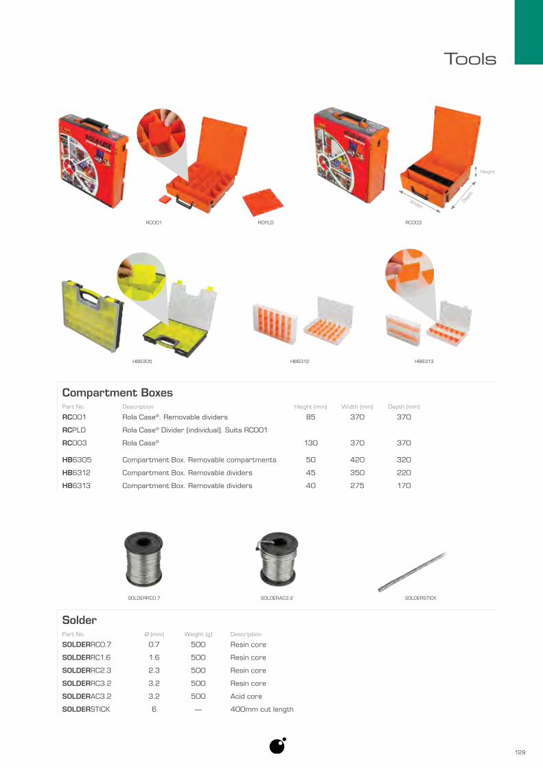
129
Tools
Compartment BoxesPart No. Description Height (mm) Width (mm) Depth (mm) RC001 Rola Case®. Removable dividers 85 370 370
RCPLD Rola Case® Divider (individual). Suits RC001
RC003 Rola Case® 130 370 370
HB6305 Compartment Box. Removable compartments 50 420 320
HB6312 Compartment Box. Removable dividers 45 350 220
HB6313 Compartment Box. Removable dividers 40 275 170
RC001 RCPLD RC003
Width
Height
HB6305 HB6312 HB6313
Dept
h
SolderPart No. Ø (mm) Weight (g) Description
SOLDERRC0.7 0.7 500 Resin core
SOLDERRC1.6 1.6 500 Resin core
SOLDERRC2.3 2.3 500 Resin core
SOLDERRC3.2 3.2 500 Resin core
SOLDERAC3.2 3.2 500 Acid core
SOLDERSTICK 6 — 400mm cut length
SOLDERRC0.7 SOLDERAC3.2 SOLDERSTICK


ElectronicsVoltage Converters 132RCD/GPO Inverters 135
Pure Sine Wave Inverters 136Combi Inverter/Chargers 138
AC to DC Battery Chargers 140DC to DC Battery Chargers 141
Power Supplies 142Battery Monitor 144
Battery Separators 143Hour Meter 145
RustStop® 146Brake Controllers 147
Idle Timers 148Flasher Units 150
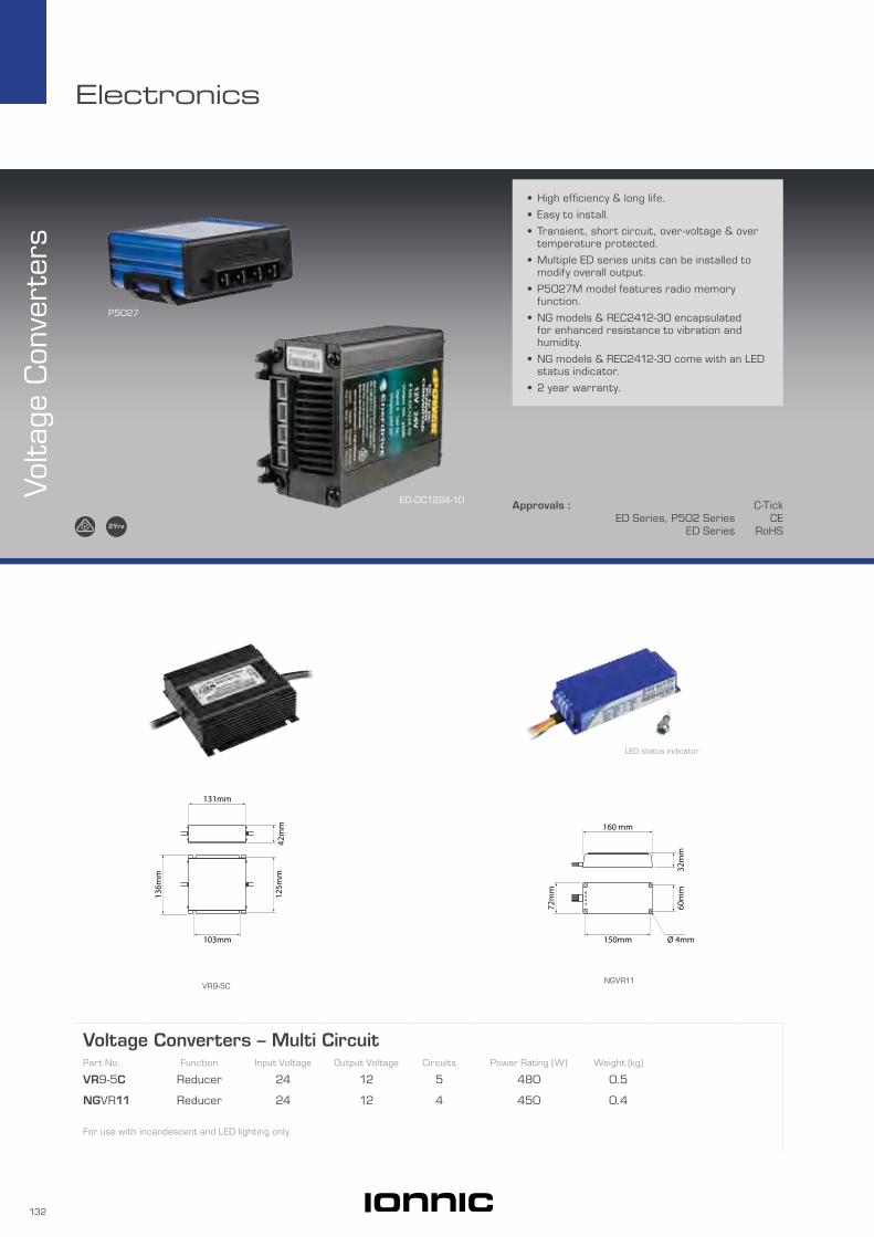
132
Electronics
• High efficiency & long life.
• Easy to install.
• Transient, short circuit, over-voltage & over temperature protected.
• Multiple ED series units can be installed to modify overall output.
• P5027M model features radio memory function.
• NG models & REC2412-30 encapsulated for enhanced resistance to vibration and humidity.
• NG models & REC2412-30 come with an LED status indicator.
• 2 year warranty.
Voltag
e Con
vert
ers
P5027
ED-DC1224-10 Approvals : C-TickED Series, P502 Series CE
ED Series RoHS
Voltage Converters – Multi CircuitPart No. Function Input Voltage Output Voltage Circuits Power Rating (W) Weight (kg) VR9-5C Reducer 24 12 5 480 0.5
NGVR11 Reducer 24 12 4 450 0.4
For use with incandescent and LED lighting only.
VR9-5CNGVR11
42m
m
131mm
125m
m
103mm
136m
m
32m
m
160 mm
150mm
72m
m
60m
m
Ø 4mm
LED status indicator

133
Electronics
Voltage ConvertersPart No. Function Input Voltage Output Voltage Circuits Current Rating (A) Weight (kg) Fig
P5027M Reducer 15 – 38 13.2 1 10 0.2 1
P5027 Reducer 15 – 38 13.2 1 10 0.2 2
VR4 Reducer 20 – 30 13.5 1 14 1.0 4
P5028 Reducer 18 – 38 13.2 1 20 0.3 3
ED-DC2412-20 Reducer 20 – 30 13.8 1 20 0.5 5
REC2412-30NG Reducer/Equaliser 22 – 30 15 1 40 0.6 6
REC1260 Reducer/Equaliser 22 – 30 15 1 60 2.6 7
ED-DC1224-10 Doubler 9 – 18 25 1 10 0.5 5
NGBC2420 Doubler/Equaliser 11.5 – 15.5 29.2 1 20 0.6 6
166m
m
175m
m
70m
m
306mm
230mm
Ø 5mm
32m
m
160 mm
150mm
60m
m
72m
m
Ø 4mm
Ø 6mm
47m
m
291mm
233 mm
125m
m
135m
m
Fig 1 Fig 2 Fig 3
Fig 4
Fig 6 Fig 7
Fig 5
77m
m
38m
m38
mm
74mm
88mm
Ø 5mm Ø 5mm
74mm
80mm
77m
m38
mm
38m
m
Ø 5mm
158mm
165mm
77m
m
38m
m38
mm
122 mm
118mm
58m
m87
mm
49m
m
Ø 5mm

134
Electronics
Voltage Converters – Galvanic IsolationPart No. Function Input Voltage Output Voltage Circuits Current Rating (A) Weight (kg)
ED-DC1212-15G Equaliser 9 – 18 12.5 1 15 0.6
ED-DC2424-7.5G Equaliser 20 – 35 24 1 7.5 0.6
ED-DC1224-7.5G Doubler 9 – 18 24 1 7.5 0.6
176 mm
168mm
87m
m
58m
m49
mm
Ø 5mm
Isolated Voltage ConverterIsolated voltage converters (also known as Galvanic Isolated) provide full dielectric isolation (no electric
contact) between input and output circuits by means of a high frequency converter, which may be
a safety requirement for certain applications.
Isolated units also have strong noise and interference blocking capabilities thus providing a
cleaner DC source for sensitive loads.
Typical applications requiring isolated voltage converters are – Communications, Entertainment &
Navigation Systems, Forklifts etc.

135
Electronics
RCD/
GPO Inverters
• AS/NZ 4763-2011 approved portable inverter.
• Pure sine wave output.
• RCD switch with M.E.N. ensures work place safety.
• High surge capacity.
• Transient, short circuit, over-voltage & over temperature protected.
• Audio alarm & warning/error codes for easy diagnosis.
• Remote switch panel included.
• 2 year warranty.
• Ideal for telecommunication, emergency, council vehicles, caravan, camper tailer & marine applications.
Input Voltage : 10.5–15.5VDCAC Output : 230VAC 50HzGeneral Power Outlet : 2Cable Length : Remote Panel 6mApprovals : CE, C-Tick & ‘e’ markedOperating Temperature : 0°C to 40°C
160m
m
261mm Ø 5mm
Ø 5mm
Ø 3.6mm52mm 325mm
64mm
90m
m
50m
m
230m
m11
0mm
215m
m
353mm
416mm
177m
m
Remote Switch
ED-IV1012R
ED-IV1012R
ED-IV2012R
RCD (Residual-Current Device) Safety Switch
Double pole dual GPO (General Power Outlet)
Remote switch panel with 6m cable
RCD/GPO InvertersPart No. Output Power (W) Output Current (A) Weight (kg)
ED-IV1012R 1000 4.3 5.5
ED-IV2012R 2000 8.7 8.5
208m
m
285m
m13
0mm
112m
m22
8mm
229mm
621mm
521mm
280m
m
267mm
Ø 5.5mm
Ø 5.5mm
ED-IV1012R
208m
m
285m
m13
0mm
112m
m22
8mm
229mm
621mm
521mm
280m
m
267mm
Ø 5.5mm
Ø 5.5mm

136
Electronics
Pure Sine WavePure sine wave inverters produce current that is close to grid AC output.
There are many advantages to pure sine wave inverters over others:
• Reliably powers devices that will not work with modified sine wave inverters.
• Very low harmonic distortion and clean power similar to utility supplied electricity.
• Inductive loads like microwaves and motors run faster, quieter and cooler.
• Reduces audible and electrical noise in fans, fluorescent lights, audio amplifiers, TV, fax and answering machines.
• Prevents crashes in computers, weird print outs and glitches in monitors.
Pur
e Sin
e W
ave
Inve
rter
s
• Pure sine wave output.
• Light & compact.
• High surge capacity.
• Transient, short circuit, over-voltage & over temperature protected.
• Audio alarm & warning/error codes for easy diagnosis.
• 12V & 24V models available.
• Australian general power outlets on 12V models.
• 12V models include a 5V USB port.
• 24V models feature LCD panel for control and monitoring.
• 12V models include remote switch panel.
• 2 year warranty.
Input Voltage : 12V Models 10.5–15.5VDC24V Models 20–32VDC
AC Output : 230VAC 50HzUSB Output : 12V Models 5V 750mAApprovals : CE, C-Tick & ‘e’ markedOperating Temperature :12V Models 0°C to 40°C
24V Models 0°C to 60°C
ED-IV1012
ED-IV1824

137
Electronics
Pure Sine Wave Inverters – 12VPart No. Output Power (W) Output Current (A) Outlet Weight (kg)
ED-IV4012 400 1.74 1 1.7
ED-IV1012 1000 4.3 1 2.9
ED-IV2012 2000 8.7 2 5.5
Pure Sine Wave Inverters – 24VPart No. Output Power (W) Output Current (A) Outlet Weight (kg)
ED-IV1024 1000 4.3 1 7.0
ED-IV1824 1800 7.8 1 7.5
LCD control panel
5V USB charging port
Australian GPO
ED-IV4012 ED-IV1012 ED-IV2012
160m
m
261mm Ø 5mm
Ø 5mm
Ø 3.6mm52mm 325mm
64mm
90m
m
50m
m
230m
m11
0mm
215m
m
353mm
416mm
177m
m
ED-IV2012
115m
m
390mm
265m
m
73mm
280m
m
Ø 6.5mm
Remote Switch Panel
160m
m
261mm Ø 5mm
Ø 5mm
Ø 3.6mm52mm 325mm
64mm
90m
m
50m
m
230m
m11
0mm
215m
m
353mm
416mm
177m
m
160m
m
261mm Ø 5mm
Ø 5mm
Ø 3.6mm52mm 325mm
64mm
90m
m
50m
m
230m
m11
0mm
215m
m
353mm
416mm
177m
m
160m
m
200mm
90m
m17
7mm
148mm Ø 5mm
Remote switch panel with 6m cable

138
Uninterruptible Power Supply
Electronics
• Configurable DC to AC power inverter, battery charger and transfer switch all in one.
• Pure sine wave output.
• Robust industrial design.
• High surge capacity.
• LCD remote control panel & temperature sensor included.
• Transient, short circuit, overvoltage & over temperature protected.
• Automatic standby function to reduce no-load consumption.
• Configurable alarm relay.
• 2 year warranty.
• Ideal for service vehicles, solar power systems, trailer homes, industrial systems and marine applications.
ED-IVC3012Input Voltage : 12V Models 10.5–16VDC
24V Models 21–32VDCAC Output : 230VAC 50Hz Approvals : C-Tick, IEC 60335-2-29Operating Temperature : -20°C to 50°C
Com
bi In
vert
er/
Cha
rger
s
The Combi Inverter/Charger is an all in one combination of a DC to AC true sine wave inverter, an advanced multi-stage battery charger and a high speed AC transfer switch.
All this is built into one compact and easy to install enclosure.
The main task of the Combi Inverter/Charger is to act as an uninterruptible AC power supply (UPS). In case of a grid/generator failure or disconnection, the Combi Inverter/Charger immediately stops charging the battery, releases the AC transfer switch and activates the inverter which takes over the supply to the connected loads.
All this is achieved so fast, even critical loads such as computers will continue to operate without problem.
Upon reconnection of the grid/generator, and if the voltage and frequency are within acceptable limits, the Combi Inverter/Charger activates the AC transfer switch and battery charger again, while deactivating the inverter. The connected loads are now supplied again by the grid/generator without interruption.
DC to AC true sine wave
inverter
Advanced multi-stage
battery charger
High speed AC transfer switch

139
Electronics
Combi Inverters/ChargersPart No. Model Output Power (W) Output Current (A) Weight (kg) Fig
ED-IVC1612 12V 1600 60 10.7 1
ED-IVC3012 12V 3000 120 19.0 2
ED-IVC1824 24V 1800 35 10.7 1
ED-IVC3524 24V 3500 70 19.0 2
ED-IVC3012
Temperature sensor with 3m cable
Remote control LCD panel for comprehensive
feedback & control
Fig 1 Fig 2
Remote Control Panel
210mm
351m
m
114mm
370m
m
132mm431mm
70m
m
130mm 36mm
210mm
351m
m
114mm
370m
m
132mm431mm
70m
m
130mm 36mm
210mm
351m
m
114mm
370m
m
132mm431mm
70m
m
130mm 36mm
210mm
351m
m
114mm
370m
m
132mm431mm
70m
m
130mm 36mm
210mm
351m
m
114mm
370m
m
132mm431mm
70m
m
130mm 36mm
210mm
351m
m
114mm
370m
m
132mm431mm
70m
m
130mm 36mm

140
Electronics
AC t
o D
C B
atte
ry C
harg
ers • Selectable outputs for different battery types.
• 4 stage charging controls: – Bulk – Absorption – Float – Maintenance.
• Adjustable control of output current via front keypad.
• Priority charge function on bank 1.
• Selectable Night Mode for silent operation.
• Optional LCD panel for remote control and monitoring.
• Transient, short circuit, over-voltage & over temperature protected.
• 12V & 24V models available.
• 2 year warranty.
Input Voltage : 90–265VACFrequency : 50–60HzOutput Circuits : 3*Battery Types : Flooded, Lithium, AGM/GELApprovals : C-Tick, AS/NZS 60335.2.29Operating Temperature : -20°C to 60°C
*1 fully independent, 2 common with diode isolation
ED-BC4012
ED-3REM
AC to DC Battery ChargersPart No. Model Output Current (A)
Output Voltage (DC)Weight (kg) Fig
Min Max
ED-BC2012 12V 20 14.2 15.5 2.4 1
ED-BC3024 24V 30 28.4 31.0 4.0 2
ED-BC4012 12V 40 14.2 15.5 2.6 1
ED-BC6012 12V 60 14.2 15.5 4.0 2
ED-3REM Optional LCD remote panel with 7.3m cable 3
3 output banks with priority charge function on bank 1
Optional LCD panel for remote control and
monitoring
207mm
86mm190mm
145m
m
295m
m
100mm
207mm
190mm
200m
m
355m
m
100mm
92mm
100m
m
29m
m92
mm
82mm
Ø 4mm
Ø 4mm
Ø 4mm
ED-BC4012
207mm
86mm190mm
145m
m
295m
m
100mm
207mm
190mm
200m
m
355m
m
100mm
92mm
100m
m
29m
m92
mm
82mm
Ø 4mm
Ø 4mm
Ø 4mm
Fig 1 Fig 2 Fig 3

141
Electronics
DC to D
C B
attery Chargers
DC to DC Battery ChargersPart No. Output Current (A) Input Voltage (DC)
Output Voltage (DC)Weight (kg) Alternate Functions∆ Fig
Min Max
BC-2412-10 10 24 13.6 14.4 0.7 — 1
NGBC2420 15* 11.5 – 15.5 26.4 29.2 0.6 Voltage Doubler 2
NGBC1222-1 22 11.5 – 15.5 13.2 14.4 0.6 — 2
REC2412-30NG 40 22 – 30 10 15 0.6 Voltage Reducer/Equaliser 2
REC1260 60 22 – 30 10 15 2.6 Voltage Reducer/Equaliser 3
ED-DCBC4012 5–50** 12/24 13.8 15.5 1.8 — 4
* 20A in Doubler Mode. ** User selectable. ∆ Alternate functions must be set prior to installation.
• Multi-stage charging controls.
• Transient, short circuit, over-voltage & over temperature protected.
• Compatible with flooded cell, lithium and AGM/GEL batteries.
• NGBC series & REC2410-30NG encapsulated for enhanced resistance to vibration and humidity.
• LED status indicator supplied with select models.
• BC-2412-10 incorporates internal resettable fuse.
• ED-DCBC4012 features solar input capability.
• ED-DCBC4012 includes temperature sensor for more accurate battery charging.
• 2 year warranty.
Output Circuits : 1Inputs : BC, REC & NGBC 1 x Battery
ED-DCBC4012 1 x Battery & SolarBattery Types : Flooded, Lithium, AGM/GELApprovals : C-TickOperating Temperature : -20°C to 60°C
ED-DCBC4012
NGBC2420
Fig 1
63m
m
114mm
136mm
59m
m
Ø 6mm124 mm
91m
m
LED status indicator (NGBC2420, NGBC1222-1,
REC2412-30NG)
32m
m60
mm
72m
m
150mm
160mm
Ø 4mm
Fig 3Fig 2
70m
m16
6mm
230mm
306mm
177m
m
Ø 5mm
Temperature sensor with 7.5m cable
Fig 4
154mm
118m
m
72mm
238m
m
168mm
Ø 5mm

142
Electronics
Pow
er S
uppl
ies
EMC : RPS12-5 EN55022-BOperating Temperature : 0°C to 80°C
• Regulated output voltage.
• Light & portable.
• Internal cooling.
• LED status indicators.
• Transient, short circuit, over-voltage & over temperature protected.
• RPS3800 features adjustable output voltage.
Power SuppliesPart No. Output Current (A) Input Voltage (AC) Output Voltage (DC) Weight (kg)
RPS12-5 2 240 13.8 1.7
RPS3078 0 – 20 220 – 240 13.8 1.3
RPS3079 0 – 12 220 – 240 13.8 1.3
RPS3800 15 – 17.4 90 –125 / 200 – 240 0 – 24* 1.1
* User selectable.
76m
m
85m
m
168mm 209mm
RPS3078, RPS3079
RPS3800
RPS12-5
67m
m
75m
m
102mm 172mm
56m
m
68m
m
150mm 195mm
RPS3800
RPS3078
Adjustable output voltage
LED status indicators

143
Electronics
Battery S
eparators
• Microprocessor-controlled battery isolators designed for use in multi-battery applications.
• Cost-effective protection against flat battery.
• Intelligent battery monitoring to prevent unwanted switching.
• Starter battery priority.
• No voltage loss.
• Surge-protected.
• 2 year warranty.
• Ideal for service vehicles, solar power systems, caravans, RVs, trailer homes, industrial systems and marine applications.
Voltage : ED-VSR 12V/24V1315-200 12V
Approvals : ED-VSR C-TickOperating Temperature : ED-VSR -10°C to 40°C
1315-200 -40°C to 60°C
Battery SeparatorsPart No.
Current Rating (A) Off Volts On VoltsWeight (kg)
Inrush Continuous @12V @24V @12V @24V ED-VSR1224-140 — 140 12.8 25.6 13.2 26.4 0.1
ED-VSR1224-160 480 160 12.8 25.6 13.2 26.4 0.5
1315-200 600 200 12.8 — 13.2 — 1.0
Ø 6mm
78m
m
46mm
46m
m
6.3m
m
6mm
ED-VSR1224-140 ED-VSR1224-160 1315-200
6.3m
m
58m
m10
8mm
51m
m
88m
m
8mm72mm
Ø 6.5mm
ED-VSR1224-140
ED-V24-160
83mm
103m
m10
2mm 7m
m51mm6.3mm Ø 8mm

144
Electronics
Battery StatusCycle between 4 status screens providing a comprehensive
understanding of the battery condition.
• Displays voltage, current, consumed amp hours & remaining battery capacity.
• 2 battery inputs.
• Configurable alarm relay.
• 500A shunt included.
• Ideal for service vehicles, forklifts, solar power systems, trailer homes, industrial systems and marine applications.
• 2 year warranty.
Battery Monitor KitPart No.
ED-EN55010
Display battery voltage to within 0.1V
Battery % remaining until fully discharged
Displays Amp-hours remaining in battery (up to 999Ah)
Net charge/discharge current going into or out of the battery
(up to 500A)
Voltage : 9–35VWeight : 145gVoltage Display : Main 0 to 35VDC
Auxiliary 2 to 35VDCCurrent Display : -999 to 999ABattery Capacity Display : 20 to 999AhApprovals : RoHSOperating Temperature : -20°C to 50°C
Bat
tery
Mon
itor
64mm 78mm
Ø 5
2mm
72mm
500A shunt included

145
Electronics
Hour MeterPart No. Digits
IHM01 6
60mm 61mm
39m
m
6.3mmØ 50.8mm Panel Cutout
Hour M
eterVoltage : 10–80VCurrent Draw : 0.16AShock : 55GVibration : 20G max. rms 10 – 80HzCase : Black PolymerBezel : Black Anodised AluminiumLens : GlassWire Length : 390mmType : ElectromechanicalAccuracy : +/- 0.02%Operating Temperature : -40 °C to 85°CApprovals : CE Marked, RoHS
• Sealed case.
• Multi-voltage operation.
• Transient voltage and reverse polarity protected.
• Glass lens.
• Aluminium bezel.
• 6 digits.
• Running indicator.
• 4mm numeral height.
• Shock & vibration resistance.
• Quartz accuracy.
• Made in the USA.
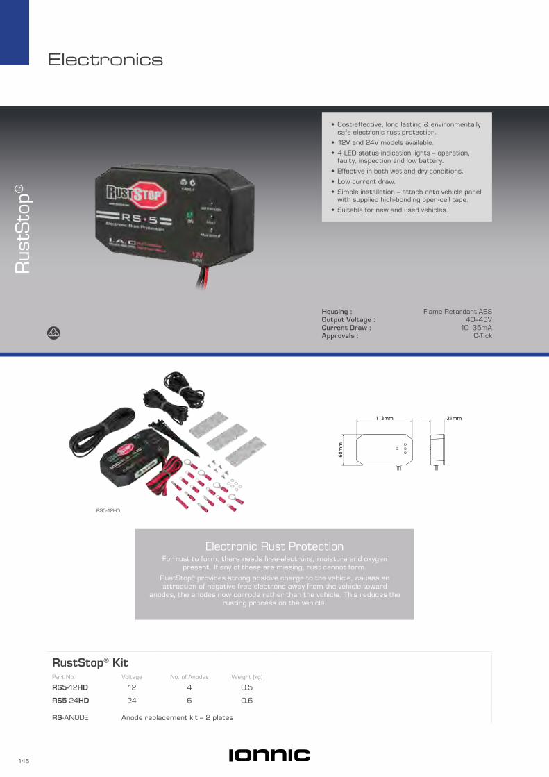
146
Electronics
RustStop® KitPart No. Voltage No. of Anodes Weight (kg)
RS5-12HD 12 4 0.5
RS5-24HD 24 6 0.6
RS-ANODE Anode replacement kit – 2 plates
Housing : Flame Retardant ABSOutput Voltage : 40–45VCurrent Draw : 10–35mAApprovals : C-Tick
Rus
tSto
p®
• Cost-effective, long lasting & environmentally safe electronic rust protection.
• 12V and 24V models available.
• 4 LED status indication lights – operation, faulty, inspection and low battery.
• Effective in both wet and dry conditions.
• Low current draw.
• Simple installation – attach onto vehicle panel with supplied high-bonding open-cell tape.
• Suitable for new and used vehicles.
RS5-12HD
21mm113mm
68m
m
Electronic Rust ProtectionFor rust to form, there needs free-electrons, moisture and oxygen
present. If any of these are missing, rust cannot form.
RustStop® provides strong positive charge to the vehicle, causes an attraction of negative free-electrons away from the vehicle toward
anodes, the anodes now corrode rather than the vehicle. This reduces the rusting process on the vehicle.

147
Electronics
Brake C
ontrollers
Approvals : RBC C-Tick
• Microprocessor technology – no time delay.
• 12V and 24V models available.
• Incorporates over-ride function for manual control.
• In-cab control & indication.
• 2 axle 12A output capability.
• EBC series plug & play installation.
• Detachable mounting bracket.
• 2 year warranty.
Brake ControllersPart No. Voltage Axles Weight (kg)
EBC-12 12 2 0.3
EBC-24 24 2 0.3
RBC-12 12 2 0.2
RBC-24 24 2 0.2
EBC-24
81mm
128m
m43
mm
EBC-12, EBC-24
82mm
79m
m41
mm
35m
m76
mm
RBC-12, RBC-24
RBC-12

148
Electronics
Idle
Tim
ers
IT11450
Voltage : 12–24VCurrent Rating : 10A max.Approvals : Adjustable – IONNIC CE, C-TickIngress Protection : Adjustable – IONNIC IP65
• Energise to run or stop models.
• Remote face on selected models.
• Multiple mounting options.
• Gauge mount models feature 30A switching capacity via serviceable external relay.
• Multi-voltage.
• Vehicle specific pre-terminated models available on request, lead times apply.
79m
m
109mm 52mm
119mm 64mm
Ø 6.5mm
Adjustable – IONNICPart No. Outputs Energise to Time Intervals Park Brake Override Description
IT11450 1 Run 1 to 12 min, 1 min increment Yes Idle timer controller unit only
IT10451 Harness with stainless steel illuminated push button switch & engraved label – 1.8m
IT11451 Harness with toggle switch, boot & pilot light – 1.8m
IT10452 Idle Timer kit – push button switch Kit contains: 1 x IT11450, 1 x IT10451
IT11452 Idle Timer kit – toggle switch Kit contains: 1 x IT11450, 1 x IT11451
BES-925/ST-1
IT10451
Illuminated push button switch
(Red)
Engraved label
Illuminated pilot light (Amber)
IT11451

149
Electronics
Adjustable – Remote FacePart No. Outputs Energise to Time Intervals (min) Park Brake Override Description
BES-925/ST-1 1 Run 0.5, 1, 2, 3, 4, 5 Yes Non-electronic engine management
BES-925/ST-3 2* Run 0.5, 1, 2, 3, 4, 5 Yes Non-electronic engine management
BES-925/ST-4 1 Run 0.5, 1, 2, 3, 4, 5 Yes Electronic engine management
BES-925/ST-5 2 Run 0.5, 1, 2, 3, 4, 5 Yes Electronic engine management
CTR-M 1 Stop 0.5, 1, 2, 3, 4, 5 No Electronic engine management
* Second output used to isolate power to EDIC (shutdown) motor during idle period.
Remote Face
130mm29mm
50m
m
Ø 8mm91mm
24m
m25
mm
Fixed – Gauge MountPart No. Outputs Energise to Time Intervals (min) Park Brake Override Description
CST500 1 Run Fixed @ 5 No Relay driven output
CST515 1 Stop Fixed @ 5 No Relay driven output
52mm
58m
m
112mm
Adjustable – X-SeriesPart No. Outputs Energise to Time Intervals Park Brake Override Description
BES-X104 1 Run 30 sec to 30 min Yes Suitable for both electronic & non-electronic engine managementBES-X105 2 Run 30 sec to 30 min Yes
Illuminated push button switch for manual stop override, mounts in supplied bracket
130mm29mm
50m
m
Ø 8mm
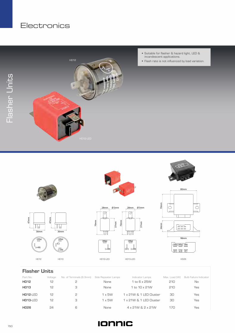
150
Electronics
Flas
her
Uni
ts
HD12
HD12-LED
• Suitable for flasher & hazard light, LED & incandescent applications.
• Flash rate is not influenced by load variation.
Flasher UnitsPart No. Voltage No. of Terminals (6.3mm) Side Repeater Lamps Indicator Lamps Max. Load (W) Bulb Failure Indicator
HD12 12 2 None 1 to 6 x 25W 210 No
HD13 12 3 None 1 to 10 x 21W 210 Yes
HD12-LED 12 2 1 x 5W 1 x 21W & 1 LED Cluster 30 Yes
HD13-LED 12 3 1 x 5W 1 x 21W & 1 LED Cluster 30 Yes
HD26 24 6 None 4 x 21W & 2 x 21W 170 Yes
HD26HD12 HD13 HD12-LED HD13-LED
Catalogues
(+49)
(C)
(49a)(49a)
(+49)
47m
m
36mm
47m
m
36mm
(49a)
(+49)
(49a)
(+49)(31)
28mm
37m
m
70m
m
Ø 5mm 28mm
37m
m
70m
m
Ø 5mm
(49)
(C)
(49a)(30b)
(c2)(31)
98mm
34m
m70
mm
80mm

CataloguesElectrical
Lighting | Safety | Electrical
Catalogues
• Battery Master Switches• Emergency Stop Switches• Switching Systems• Toggle Switches• Rocker Switches• Relay & Solenoids• Circuit Protection
To get your copy visit ionnic.com
• DT Series• DTM Series• DTP Series• DTHD Series• HD10 Series• HD30/HDP20 Series• DRC Series• Contacts & Plugs• Deutsch Connector Tools
To get your copy visit ionnic.com
Connectors
SRC2015
SRC
2015
Switches Relays &
Circuit Protection


BulbsBulbs 154

154
Bulbs
Bul
bs
64156LTS
64196LTS
98-H1
6480
24mm
14.5
mm
10mm
39m
m17
mm
Halogen – H1Part No. Voltage Watt Base Description
64150 12 55 P14.5s Original Line
64150NBUDUO* 12 55 P14.5s Night Breaker Unlimited
84150 12 55 P14.5s Long Life
62200 12 100 P14.5s Off Road – Rally
64155 24 70 P14.5s Original Line
64155LTS 24 70 P14.5s Truckstar
84155 24 70 P14.5s Long Life
* Pack of 2.
45m
m25
mm
32m
m
Fig 2
43.5mm
43.5
mm
50m
m32
mm
Fig 1
HID Part No. Voltage Watt Base Fig
80037 12–24 35 D1S 1
80009 12–24 35 D2S 2
• Wide range of bulbs including LED, HID, halogen and incandescent.
• Truckstar models feature: – Osram patented Single Coil technology. – Up to 100% more light output compare with conventional 24V bulbs. – More then twice the life of conventional 24V bulbs. – High vibration resistance. – Ideal for trucks and other heavy duty applications.

155
Bulbs
Halogen – H417mm
82m
m45
mm
17mm
92m
m43
mm
Fig 1 Fig 2
Part No. Voltage Watt Base Description Fig
64193 12 60/55 P43t Original Line 1
64193CB 12 65/55 P43t Cool Blue 1
64193NBUDUO* 12 65/55 P43t Night Breaker Unlimited 1
62203 12 100 P43t Off Road – Rally 1
64196 24 75/70 P43t Original Line 1
64196LTS 24 75/70 P43t Truckstar 1
64198 12 60/55 P45t Off Road – Rally 2
64199 24 75/70 P45t Off Road – Rally 2
* Pack of 2.
Halogen – H7
11mm
26mm
42m
m15
mm
34mm
Part No. Voltage Watt Base Description
64210 12 55 PX26d Original Line
64210CB 12 55 PX26d Cool Blue
64210NBU 12 55 PX26d Night Breaker Unlimited
64215 24 70 PX26d Original Line
Halogen – H9
11.7mm
43m
m
19mm
11.7mm
43m
m
19mm
Part No. Voltage Watt Base Description
64213 12 65 PGJ 19-5 Original Line
Halogen – H3
22mm
11mm
31m
m9m
m
Part No. Voltage Watt Base Description
64151 12 55 PK22S Original Line
64151SUP 12 55 PK22S +30
62201 12 100 PK22S Off Road – Rally
64156 24 70 PK22S Original Line
64156LTS 24 70 PK22S Truckstar
H34845 48 45 PK22S

156
Bulbs
55m
m
12.4mm
20mm
55m
m
12.4mm
20mm Halogen – HB3Part No. Voltage Watt Base Description
9005 12 60 20d Original Line
9005CB 12 60 20d Cool Blue
55m
m
12.4mm
22mm
55m
m
12.4mm
22mm Halogen – HB4Part No. Voltage Watt Base Description
9006 12 51 P22d Original Line
9006CB 12 51 P22d Cool Blue
70m
m
17mm
33.85mm
70m
m
17mm
33.85mm Halogen – HB5Part No. Voltage Watt Base Description
9007 12 65/55 PX29t Original Line
40.5
mm
10mm
9mm
40.5
mm
10mm
9mm
Halogen – MiniaturePart No. Voltage Watt Base Description
64136 12 21 BAY9s Original Line
64138 24 21 BAY9s Original Line
Fig 1
30m
m
9mm
Fig 2
41m
m
12mm
Halogen – Bi-PinPart No. Voltage Watt Base Fig
059-024/10W 24 10 G4 1
059-024/20W 24 20 G4 1
060-012/50W 12 50 G6.35 2
060-012/100W 12 100 G6.35 2
060-024/35W 24 35 G6.35 2
060-024/100W 24 100 G6.35 2
899-911 12 35 G6.35 2
899-912 24 35 G6.35 2
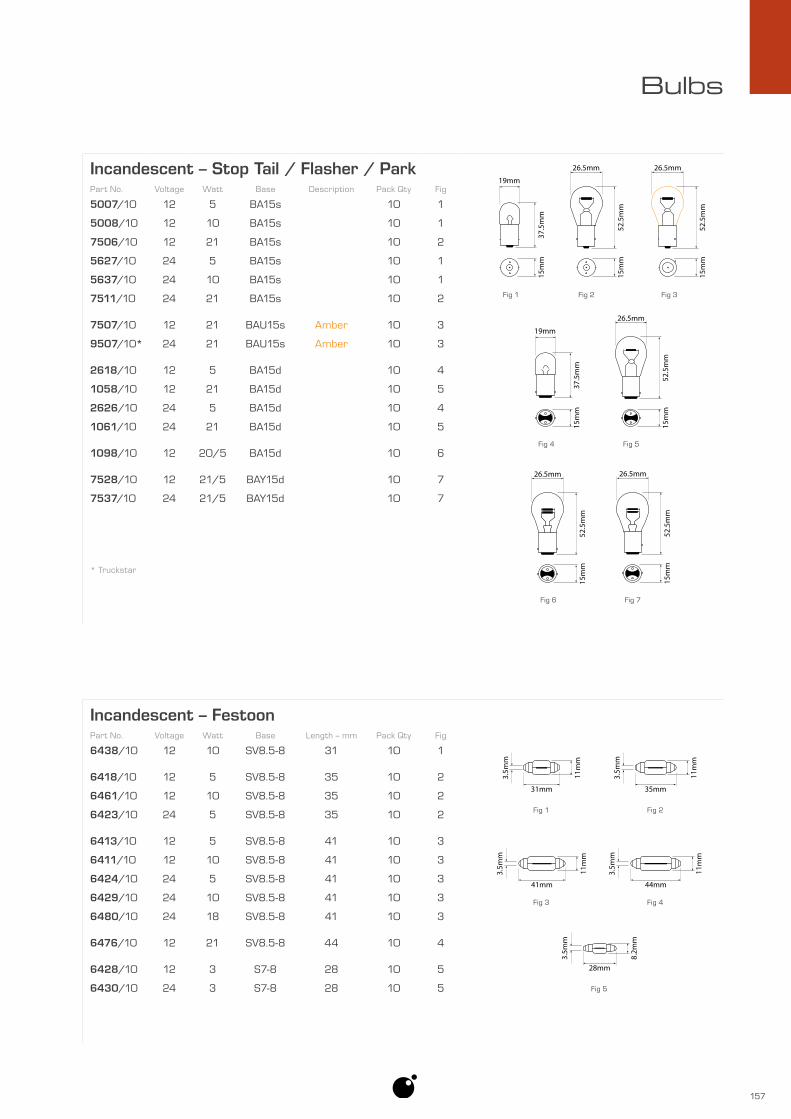
157
Bulbs
Incandescent – Festoon
28mm
8.2m
m
3.5m
m
Fig 5
Fig 1
31mm
11m
m
3.5m
m
35mm
11m
m
3.5m
m
Fig 2
41mm
11m
m
3.5m
m
Fig 3 Fig 4
44mm
11m
m
3.5m
m
Part No. Voltage Watt Base Length – mm Pack Qty Fig
6438/10 12 10 SV8.5-8 31 10 1
6418/10 12 5 SV8.5-8 35 10 2
6461/10 12 10 SV8.5-8 35 10 2
6423/10 24 5 SV8.5-8 35 10 2
6413/10 12 5 SV8.5-8 41 10 3
6411/10 12 10 SV8.5-8 41 10 3
6424/10 24 5 SV8.5-8 41 10 3
6429/10 24 10 SV8.5-8 41 10 3
6480/10 24 18 SV8.5-8 41 10 3
6476/10 12 21 SV8.5-8 44 10 4
6428/10 12 3 S7-8 28 10 5
6430/10 24 3 S7-8 28 10 5
Incandescent – Stop Tail / Flasher / ParkPart No. Voltage Watt Base Description Pack Qty Fig
5007/10 12 5 BA15s 10 1
5008/10 12 10 BA15s 10 1
7506/10 12 21 BA15s 10 2
5627/10 24 5 BA15s 10 1
5637/10 24 10 BA15s 10 1
7511/10 24 21 BA15s 10 2
7507/10 12 21 BAU15s Amber 10 3
9507/10* 24 21 BAU15s Amber 10 3
2618/10 12 5 BA15d 10 4
1058/10 12 21 BA15d 10 5
2626/10 24 5 BA15d 10 4
1061/10 24 21 BA15d 10 5
1098/10 12 20/5 BA15d 10 6
7528/10 12 21/5 BAY15d 10 7
7537/10 24 21/5 BAY15d 10 7
* Truckstar
Fig 1
37.5
mm
15m
m
19mm
Fig 2
52.5
mm
15m
m
26.5mm
Fig 3
52.5
mm
15m
m
26.5mm
Fig 4
37.5
mm
15m
m
19mm
Fig 5
52.5
mm
15m
m
26.5mm
Fig 6
52.5
mm
15m
m
26.5mm
Fig 7
52.5
mm
15m
m
26.5mm

158
Bulbs
Fig 2Fig 1
23m
m
9mm
21m
m
7mm
Incandescent – MiniaturePart No. Voltage Watt Base Pack Qty Fig
3796/10 12 2 BA9s 10 1
3797/10 24 2 BA9s 10 1
3894/10 12 3 BA9s 10 1
3893/10 12 4 BA9s 10 1
3930/10 24 4 BA9s 10 1
2696/10 12 2 BA7s 10 2
2692/10 24 2 BA7s 10 2
20m
m
5mm
23.5
mm
5mm
26.8
mm
10.3mm
47.5
mm
20.5mm
38.3
5mm
15.7mm
Fig 1
Fig 4
Fig 2
Fig 5
Fig 3
Incandescent – WedgePart No. Voltage Watt Base Pack Qty Fig
7443/10 12 21/5 W3x16q 10 1
2721/10 12 1.2 W2x4.6d 10 2
2741/10 24 1.2 W2x4.6d 10 2
2821/10 12 3 W2.1x9.5d 10 3
2840/10 24 2 W2.1x9.5d 10 3
2841/10 24 3 W2.1x9.5d 10 3
2845/10 24 5 W2.1x9.5d 10 3
2825/10 12 5 W2.1x9.5d 10 3
921/10 12 16 W2.1x9.5d 10 4
2741MF/10* 24 1.2 B8.5d 10 5
* 2741MF/10 has a plastic base.
Fig 1
52m
m40
mm
24mm
48m
m
Fig 2
47m
m46
mm
48m
m
38mm
Fig 3
49m
m44
mm
48m
m
34mm
LED – Headlamp Insert KitsPart No. Voltage Base Type Fig
98-H1 12–24 P14.5s H1 1
98-H4 12–24 P43t H4 2
98-H7 12–24 PX26d H7 3
Each kit contains 2 x LED headlights plus fitting accessories.
Not ADR approved. For off road use only.
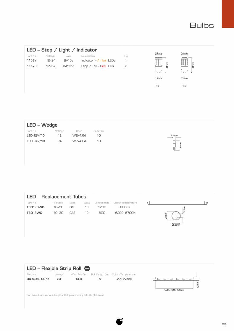
159
Bulbs
LED – Stop / Light / Indicator
Fig 2Fig 1
44m
m
16mm
15mm
44m
m
20mm
15mm
Part No. Voltage Base Description Fig
1156Y 12–24 BA15s Indicator – Amber LEDs 1
1157R 12–24 BAY15d Stop / Tail – Red LEDs 2
LED – Replacement Tubes
28m
m
25.5mm
12m
m
Part No. Voltage Base Watt Length (mm) Colour Temperature
T8D120WC 10–30 G13 18 1200 6000K
T8D18WC 10–30 G13 12 600 6200–6700K
LED – Wedge
44m
m
5.5mm
Part No. Voltage Base Pack Qty
LED-12V/10 12 W2x4.6d 10
LED-24V/10 24 W2x4.6d 10
LED – Flexible Strip Roll
Cut Lengths 100mm
12m
m
Part No. Voltage Watt Per 5m Roll Length (m) Colour Temperature
BA-5050-60/5 24 14.4 5 Cool White
Can be cut into various lengths. Cut points every 6 LEDs (100mm).

160
Index
Part No. Page
0
0411-204-1605 1240411-240-2005 1240411-291-1405 1240411-310-1605 1240411-336-1605 1240411-337-1205 1240411-353-0805 124059-024/10W 156059-024/20W 156
060-012/100W 156060-012/50W 156
060-024/100W 156060-024/35W 156
1
1011-026-0205 82103349 116
103349-302 116103349R 1161058/10 1571061/10 1571098/10 157114008 124114009 124114010 124
1156Y 1591157R 159
1200068/100 71200069/100 71200070/50 71200089/50 71200100/50 71200135/50 71200178/50 71200224/50 71200291/25 71200372/25 71200500/25 7
1200807/5000 71200808/3300 71200810/3000 71200813/2000 71200817/1100 71200822/700 71200829/450 7
12010105 8312010300/100 8712010300/100 89
12014012 12512014254 121
12077411/100 8912085270 12112094429 12512094430 125
12129409/100 8712129493/100 89
1315-200 14315324980/100 8715324980/100 8915324981/100 8715324982/100 8715324982/100 8915324983/100 871927304/100 81927306/100 81927308/50 81927311/50 8
1940008/50 91940011/50 91940013/50 91940015/50 91940019/50 91940026/25 9
Part No. Page
2
2618/10 1572626/10 157
265/1 62265/3 62265/4 62265/5 62265/7 62
2692/10 1582696/10 1582721/10 1582741/10 158
2741MF/10 158281934-2/100 87282081-1/100 87
2821/10 1582825/10 1582840/10 1582841/10 1582845/10 158
3
3771BUS-2 903771BUS-3 90
3796/10 1583797/10 158
37989 3937990 3937992 3937994 3937999 39
3893/10 1583894/10 1583930/10 1583AG1/10 80
3AG10/10 803AG15/10 803AG20/10 803AG25/10 803AG3/10 80
3AG30/10 803AG35/10 80
3AG5/10 803AG7.5/10 80
5
5007/10 1575008/10 157
50856 6050860 6050861 6050862 6050864 6050866 6050868 6050870 6050872 60
5627/10 1575637/10 157
6
62200 15462201 15562203 155
6411/10 1576413/10 157
64136 15664138 15664150 154
64150NBUDUO 15464151 155
64151SUP 155
Part No. Page
64155 15464155LTS 154
64156 15564156LTS 1556418/10 157
64193 15564193CB 155
64193NBUDUO 15564196 155
64196LTS 15564198 15564199 15564210 155
64210CB 15564210NBU 155
64213 15564215 155
6423/10 1576424/10 1576428/10 1576429/10 1576430/10 1576438/10 1576461/10 1576476/10 1576480/10 157
6AC-16/10 806AC-25/10 806AC-5/10 806AC-8/10 80
7
7443/10 1587506/10 1577507/10 1577511/10 1577528/10 1577537/10 157
7704489 1257704496 125
7807270/10 277807272/10 277807276/10 277807278/10 277807280/10 277807282/10 277807288/10 277807296/10 27
7814145 1237814146 1237814147 123
8
80009 15480037 154
8211000/10 128211000/10 378211019/10 128211019/10 378211027/10 128211027/10 378211035/10 128211035/10 378211060/10 128211060/10 378211094/10 128211094/10 378211108/10 128211108/10 378211124/10 128211124/10 37
84150 15484155 154
899-911 156899-912 156
Part No. Page
9
9001511 149001511 1289001520 149001520 1289001543 149001543 1289001550 149001550 1289001552 149001552 1289001555 149001555 1289001558 149001558 1289001561 149001561 1289001564 149001564 1289001567 149001567 128
9005 1569005CB 156
9006 1569006CB 156
9007 156921/10 158
9507/10* 1579620/10 379621/10 379622/10 37
968855-1/100 879805911/10 129805912/10 129805913/10 129805914/10 129805916/10 129805917/10 129805925/10 129805939/10 119805940/10 119805941/10 11
9805941/100 119805942/10 119805943/10 119805944/10 119805945/10 119806082/10 239806086/10 239806088/10 239806089/10 239806090/10 239806091/10 239806092/10 239806093/10 239806095/10 239806096/10 239806099/10 239806100/10 259806101/10 249806102/10 259806103/10 259806104/10 249806107/10 259806108/10 25
9806108/100 259806110/10 259806111/10 24
9806111/100 249806112/10 259806113/10 259806114/10 259806115/10 24
9806115/100 249806118/10 24
Part No. Page
9806120/10 259806121/10 259806124/10 259806126/10 259806127/10 249806129/10 259806130/10 249806131/10 249806133/10 249806135/10 25
9806135/100 259806136/10 25
9806136/100 259806137/10 259806138/10 24
9806138/100 249806141/10 25
9806141/100 259806143/10 259806146/10 259806149/10 259806158/10 249806159/10 249806160/10 249806166/10 259806167/10 259806172/10 249806196/10 239817079/10 26
9817079/100 269817083/10 269817200/10 269817201/10 26
9817201/100 269817202/10 269817203/10 269817302/10 269817303/10 26
9817303/100 269817304/10 269817305/10 26
9817305/100 269817306/10 269817308/10 269817309/10 269817310/10 26
9817310/100 269817311/10 26
98-H1 15898-H4 15898-H7 158
A
AMB19B/100 33AMB25B/100 33
AMG040 93AMG060 93AMG080 93AMG100 93AMG125 93AMG150 93AMG175 93AMG200 93AMG225 93AMG250 93AMG300 93AMG500 93AMGFH1 95AMGFH2 94AMI100 92AMI125 92AMI150 92AMI175 92AMI200 92
AMI30 92AMI40 92

161
Index
Part No. Page
AMI50 92AMI60 92AMI70 92AMI80 92AMIFH 95
ANL250 93ANL275 93ANL300 93ANL400 93ANL500 93
ANL035-B 93ANL040-B 93ANL050-B 93ANL060-B 93ANL080-B 93ANL100-B 93ANL125-B 93ANL130-B 93ANL150-B 93ANL175-B 93ANL200-B 93ANL225-B 93ANL250-B 93ANL300-B 93ANL325-B 93ANL350-B 93ANL400-B 93ANL500-B 93ANL600-B 93ANL675-B 93ANL750-B 93
ANLFH1 95
B
B109-7046-2 97B109-7046-3 97B109-7046-4 97B109-7046-5 97B109-7046-6 97B109-7046-7 97
BA-5050-60/5 159BC-2412-10 141
BES-925/ST-1 149BES-925/ST-3 149BES-925/ST-4 149BES-925/ST-5 149
BES-X104 149BES-X105 149
BF1/10 79BF10/10 79
BF10/100 79BF15/10 79
BF15/100 79BF2/10 79
BF2/100 79BF20/10 79
BF20/100 79BF25/10 79
BF25/100 79BF3/10 79
BF3/100 79BF30/10 79
BF30/100 79BF4/10 79
BF4/100 79BF40/10 79
BF40/100 79BF5/10 79
BF5/100 79BF7.5/10 79
BF7.5/100 79BF-KIT 81
BHS80 37BHS81 37
Part No. Page
C
C10BLK-100 111C10ONG 111
C10RED-100 111C10-TWIN 111C120ONG 111
C120RED-50 111C16ONG 111
C16-TWIN 111C25BLK-100 111
C25ONG 111C25RED-100 111
C25-TWIN 111C35BLK-100 111
C35ONG 111C35RED-100 111
C35-TWIN 111C50BLK-50 111
C50ONG 111C50RED-50 111
C50-TWIN 111C70BLK-50 111
C70ONG 111C70RED-50 111C95BLK-50 111
C95ONG 111C95RED-50 111
CB121-10 71CB121-10M 71
CB121-15 71CB121-15M 71
CB121-20 71CB121-20M 71
CB121-25 71CB121-25M 71
CB121-30 71CB121-30M 71
CB121-40 71CB121-40M 71
CB121-50 71CB121-50M 71
CB121-8 71CB121BOOT-BLK 71CB121BOOT-RED 71
CB123-10 71CB123-15 71CB123-20 71CB123-25 71CB123-30 71CB123-40 71CB174-10 70CB174-15 70CB174-30 70
CB184F-100 73CB184F-120 73CB184F-150 73CB184F-30 73CB184F-40 73CB184F-50 73CB184F-70 73CB184F-80 73
CB184P-100 73CB184P-120 73CB184P-60 73CB184P-80 73
CB185F-100 73CB185F-120 73CB185F-150 73CB185F-30 73CB185F-40 73CB185F-50 73CB185F-60 73CB185F-70 73CB185F-80 73
CB187F-100 74
Part No. Page
CB187F-120 74CB187F-150 74CB187F-200 74
CB187F-30 74CB187F-40 74CB187F-50 74CB187F-60 74CB187F-70 74CB187F-80 74
CB192-20M 76CB192-30M 76
CB227-10 77CB227-15 77CB227-20 77CB227-25 77CB227-30 77
CB227-5 77CB227-7.5 77CB233-10 77CB233-15 77CB233-20 77CB233-25 77CB233-30 77
CB233-5 77CB233-7.5 77CB255-10 74CB255-15 74CB255-20 74CB255-25 74CB255-30 74CB255-35 74CB255-40 74CB255-50 74
CBF-KIT 81CBW31-10 75CBW31-15 75CBW31-20 75
CBW31-5 75CC58 115
CDM03 71CDM05 71CDM10 71CDM15 71CDM20 71CDM30 71CDM40 71CDM60 71
CG12/10 31CG16/10 31CG16SR 64
CG20/10 31CG25/10 31CG32/10 31CG40/5 31
CG50 31CG63 31
CM3504 99CST500 149CST515 149CT102 32
CT102B 32CT143 32
CT143B 32CT194 32
CT194B 32CT200B 32
CT280 32CT280B 32CT292B 32CT300B 32CT370B 32CT373B 32CT432B 32CT533B 32
CT550HB 32CT762B 32
CTC-12B/10 48
Part No. Page
CTC-16B/10 48CTC-24B/10 48CTC-3B/10 48CTC-6B/10 48
CTP12 21CTP16 21
CTPB20 21CTPB28 21
CTR-M 149CTS6B/100 33CTS8B/100 33
D
DE-D2681 120DE-D2682 120DE-D2683 125DE-D7000 121DE-DET12 120DE-DET16 120DE-DET20 120DE-DET-RT 125
DW12-40BLK/20 54DW12-40RED/20 54
DW12BLK 54DW12RED 54
DW18-40BLK/10 54DW18-40RED/10 54
DW18BLK 54DW18RED 54
DW24-50BLK/5 54DW24-50RED/5 54
DW24BLK 54DW24RED 54DW39BLK 54DW39RED 54
DW3BLK 54DW3RED 54
DW4.8BLK 54DW4.8RED 54
DW6BLK 54DW6RED 54
DW9-40BLK/20 54DW9-40RED/20 54
DW9BLK 54DW9RED 54
DW-KIT 53DWR12BLK/25 54DWR12RED/25 54DWR18BLK/25 54DWR18RED/25 54DWR24BLK/25 54DWR24RED/25 54DWR3BLK/200 54DWR3RED/200 54
DWR4.8BLK/100 54DWR4.8RED/100 54
DWR6BLK/100 54DWR6RED/100 54DWR9BLK/50 54DWR9RED/50 54
E
EBC-12 147EBC-24 147
ED-3REM 140ED-BC2012 140ED-BC3024 140ED-BC4012 140ED-BC6012 140
ED-DC1212-15G 134ED-DC1224-10 133
ED-DC1224-7.5G 134ED-DC2412-20 133
ED-DC2424-7.5G 134ED-DCBC4012 141
Part No. Page
ED-EN55010 144ED-IV1012 137
ED-IV1012R 135ED-IV1024 137ED-IV1824 137ED-IV2012 137
ED-IV2012R 135ED-IV4012 137
ED-IVC1612 139ED-IVC1824 139ED-IVC3012 139ED-IVC3524 139
ED-VSR1224-140 143ED-VSR1224-160 143
EGG50 127ENG-BATTERY 67ENG-BATTISO 67
ENG-STARTER 67ENG-STARTERISO 67
ES2000-1 55ES2000-2 55ES2000-3 55ES2000-4 55
F
FH01 83FH02 83FH03 83FH04 83FH05 83FH06 83FH07 83FH08 88FH09 88FH10 85
FH108 84FH11 85FH12 86FH14 82FH15 82FH16 82FH17 82FH18 85FH19 82FH20 86
FH207 84FH208 84
FH210A 84FH210A-LD 84
FH211 84FH22 90
FLF100A 80FLF20A 80FLF30A 80FLF40A 80FLF50A 80FLF60A 80FLF80A 80
FLM100A 80FLM20A 80FLM30A 80FLM40A 80FLM50A 80FLM60A 80FLM80A 80
FP 64FP2 64FP3 64
H
H0300 59H0301 59H0302 59H0304 59
162
Index
Part No. Page
H0306 59H0308 59H0310 59H0420 63H0421 63H0422 63H0423 63H0424 63H0427 63H0429 63H1590 63
H34845 155HB6305 129HB6312 129HB6313 129
HC1 64HD12 150
HD12-LED 150HD13 150
HD13-LED 150HD26 150
HDT-04-08 120HDT-48-00 120HDT-50-00 120
HP-CT19 38HP-FT19 38
HS1.5BLK 52HS1.5RED 52
HS10-40BLK/40 51HS10-40RED/40 51
HS10BLK 52HS10RED 52
HS13-40BLK/40 51HS13-40RED/40 51
HS13BLK 52HS13RED 52HS2.5BLK 52HS2.5RED 52
HS20-40BLK/20 51HS20-40RED/20 51
HS20BLK 52HS20RED 52
HS25-50BLK/10 51HS25-50RED/10 51
HS25BLK 52HS25RED 52HS3.5BLK 52HS3.5RED 52HS30BLK 52HS30RED 52HS40BLK 52HS40RED 52HS50BLK 52HS50RED 52
HS5BLK 52HS5RED 52
HS76BLK 52HS76RED 52
HS7BLK 52HS7RED 52
HSD10BLK/10 51HSD10RED/10 51HSD13BLK/5 51HSD13RED/5 51
HSD2.5BLK/20 51HSD2.5RED/20 51
HSD20BLK/5 51HSD20RED/5 51HSD25BLK/5 51HSD25RED/5 51
HSD3.5BLK/20 51HSD3.5RED/20 51
HSD5BLK/10 51HSD5RED/10 51HSD7BLK/10 51HSD7RED/10 51
HS-KIT 51
Part No. Page
HSR1.5BLK/200 52HSR1.5RED/200 52HSR100BLK/25 52HSR100RED/25 52HSR10BLK/50 52HSR10RED/50 52HSR13BLK/50 52HSR13RED/50 52
HSR2.5BLK/200 52HSR2.5RED/200 52
HSR20BLK/50 52HSR20RED/50 52HSR25BLK/50 52HSR25RED/50 52
HSR3.5BLK/200 52HSR3.5RED/200 52
HSR30BLK/50 52HSR30RED/50 52HSR40BLK/25 52HSR40RED/25 52HSR50BLK/25 52HSR50RED/25 52HSR5BLK/100 52HSR5RED/100 52HSR7BLK/50 52HSR7RED/50 52
HT-0060 122HT-0203 122HT-0460 123HT-0560 122HT-0580 123
HT-10 126HT-11 126HT-12 126HT-14 126HT-15 126HT-16 126HT-19 45HT-19 46HT-21 123HT-22 123
HT-2400 127HT-2449 127HT-2495 127HT-2496 127
HT-30 126HT-31 126HT-34 33HT-34 126
HT-4023 122HT-4220 122HT-4510 122HT-4560 122HT-6000 127HT-6100 127HT-6130 127HT-6180 127HT-6200 127HT-6325 127HT-6500 127HT-6600 127HT-7200 125
HT-K2680 121
I
IHM01 145IN4004/10 99IN5408/10 99
IT102 33IT10451 148IT10452 148IT11450 148IT11451 148IT11452 148
Part No. Page
L
LED-12V/10 159LED-24V/10 159LMG2-1-001 96LMG3-1-001 96LMG5-1-001 96
LMI-F-M 97LMI-I-M 97
LT10/250 10LT10/30 10
LT13/150 10LT13/30 10
LT16/100 10LT16/30 10
LT20/100 10LT20/30 10LT25/10 10LT25/50 10LT30/10 10LT30/50 10LT36/25 10LT7/400 10LT7/50 10
M
M2F10/10 79M2F15/10 79M2F20/10 79M2F25/10 79M2F30/10 79
M2F5/10 79M2F7.5/10 79
M2F-KIT 81M3F-10/10 79M3F-15/10 79M3F-5/10 79
M3F-7.5/10 79MB100 79MB20 79MB30 79MB40 79MB50 79MB60 79MB70 79MB80 79
MCBF10/10 78MCBF15/10 78MCBF20/10 78MCBF25/10 78MCBF30/10 78
MCBF5/10 78MCBF7.5/10 78
MCBF-KIT 81MF10/10 78
MF10/100 78MF15/10 78
MF15/100 78MF2/10 78
MF2/100 78MF20/10 78
MF20/100 78MF25/10 78
MF25/100 78MF3/10 78
MF3/100 78MF30/10 78
MF30/100 78MF35/10 78
MF35/100 78MF4/10 78
MF4/100 78MF5/10 78
MF5/100 78MF7.5/10 78
MF7.5/100 78
Part No. Page
MFFL100A 80MFFL20A 80MFFL30A 80MFFL40A 80MFFL50A 80MFFL60A 80MFFL80A 80
MF-KIT 81MFL100A 79MFL20A 79MFL30A 79MFL40A 79MFL50A 79MFL60A 79MFL80A 79MTS101 65MTS301 65MTS401 65MTS403 65MTS508 65
MW12 55MW22 55MW27 55MW35 55MW40 55MW56 55MW72 55
N
NGBC1222-1 141NGBC2420 133NGBC2420 141
NGVR11 132NITTO21/10 38
NO.15 38
P
P5027 133P5027M 133
P5028 133PH275BK 116
PH275BK-100 116PH375BK 116
PH375BK-100 116PID41 98PID42 98PID6A 98
PM194B 33P-MSBFH/5 82PS0.25/10 34
PS01/10 34PS02/10 34PS03/10 34PS04/10 34PS05/10 34PS06/10 34PS07/10 34PS08/10 34PS09/10 34PS10/10 34PS11/10 34PS12/10 34PS13/10 34PS14/10 34PS15/10 34
PSN0.5/100 36PSN01.5/100 36
PSN01/100 36PSN02/100 36PSN03/100 36PSN04/100 36PSP0.25/10 35PSP0.5/10 35PSP01/10 35PSP02/10 35
Part No. Page
PSP03/10 35PSP04/10 35PSP05/10 35PSP06/10 35PSP07/10 35PSP08/10 35PSP09/10 35PSP10/10 35PSP11/10 35PSP12/10 35
PSPHD04/10 36PSPHD05/10 36PSPHD06/10 36PSPHD07/10 36PSPHD08/10 36PSPHD09/10 36PSPHD10/10 36PSPHD11/10 36PSPHD12/10 36PSPHD13/10 36PSPHD14/10 36PSPHD15/10 36PSPHD16/10 36PSPHD17/10 36PSPHD18/10 36
PV12/1.5G 116PV12/1G 116
PV18/1.5G 116PV18/1G 116
PV18/2.5G 116PV25/1.5G 116
PV25/1G 116PV4/1G 116
PVC10/200 44PVC10/25 44
PVC12/100 44PVC12/25 44
PVC16/100 44PVC16/25 44
PVC20/100 44PVC20/25 44PVC25/50 44PVC30/50 44PVC35/50 44
PVC4/25 44PVC4/250 44PVC40/50 44PVC6/200 44
PVC6/25 44PVC8/200 44
PVC8/25 44PVCTBLK/10 38
PVCTWHT/10 38P-WSBFH/5 82
P-WSBFH-TWIN 82
Q
QK2BSL/10 98QK4BSL/10 98
R
RBC-12 147RBC-24 147RC001 129RC003 129RC013 65RC014 65RC022 65RC031 65RC032 65RCPLD 129
REC1260 133REC1260 141
REC2412-30NG 133REC2412-30NG 141

163
Index
Part No. Page
RG1-12/10 30RG1-12/50 30RG1-16/10 30RG1-16/50 30RG1-19/10 30RG1-19/50 30RG1-23/10 30RG1-23/50 30RG1-29/25 30RG1-29/5 30
RG1-38/25 30RG1-38/5 30
RG1-48/10 30RPS12-5 142
RPS3078 142RPS3079 142RPS3800 142RS5-12HD 146RS5-24HD 146RS-ANODE 146
S
S5503 70S5505 70S5510 70S5515 70S5520 70S5525 70S5530 70S5535 70
S55BOOT 70SB08/100 31SB10/100 31SB13/100 31SB14/100 31SB16/100 31SB22/100 31
SBA0712 59SBA0811 59SBA1010 59SBA1212 59
SBA1212S 59SBA1217 59SBA1417 59
SBA1525-1 59SBB0812 58SBB1010 58SBB1115 58SBB1924 58SBB2230 58
SBH1212S 60SBH1217 60SBH2020 60
SBH2819-1 60SD10M16/5 19
SD10M1690/5 19SD12M16/5 19
SD12M1690/5 19SD12M20/5 19SD12PG11/5 19SD16M16/5 19
SD16M1690/5 19SD16M20/5 19
SD16M2090/5 19SD16PG13/5 19SD20M20/5 19
SD20M2090/5 19SD20PG16/5 19SD25M25/5 19
SD25M2590/5 19SD25M32/5 19
SD32M32 19SD32M3290 19
SD32PG29 19SD40M40 19SD50M50 19
Part No. Page
SDLM105 72SDLM150 72SDLM50 72SDLM60 72SDLM80 72
SE10 20SE12 20SE20 20SE25 20
SE2520 20SE25X12 21
SEM10M12/5 17SEM12M12/5 17SEM12M16/5 17
SEM12M1690/5 17SEM16M16/5 17
SEM16M1690/5 17SEM16M20/5 17
SEM16M2090/5 17SEM20M20/5 17
SEM20M2090/5 17SEM20M25/5 17
SEM20M2590/5 17SEM25M25/5 17
SEM32M32 17SEM32M3290 17
SEM40M40 17SEM40M4090 17
SEM50M63 17SEM50M6390 17
SEM8PG7/5 17SF01 15SF02 15SF03 15SF04 15SF05 15SF06 15SF12 15
SF1208/5 22SF13 15SF14 15
SF1612/5 22SF2012/5 22SF2016/5 22SF2512/5 22SF2516/5 22SF2520/5 22
SIPR01 61SIPR02 61
SJ03/5 13SJ05/5 13SJ06/5 13SJ12/5 13SJ16/5 13SJ20/5 13SJ25/5 13
SJ32 13SJ40 13
SM143B 33SM194B 33
SM200812/10 26SM251225/10 26SOLDERAC3.2 129SOLDERRC0.7 129SOLDERRC1.6 129SOLDERRC2.3 129SOLDERRC3.2 129SOLDERSTICK 129
SRS43 55ST01 66
ST-CLIP/10 27SY2900B/100 41
SY2900-BLK 41SY2900R/100 41
SY2900-RED 41SY2912B/100 40
SY2912-BLK 40
Part No. Page
SY2912R/100 40SY2912-RED 40
SY2914B/100 40SY2914-BLK 40
SY2914R/100 40SY2914-RED 40
SY2917B/100 40SY2917-BLK 40
SY2917R/100 40SY2917-RED 40
SY2919B/100 40SY2919-BLK 40
SY2919R/100 40SY2919-RED 40
SY2960B/100 41SY2960-BLK 41
SY2960R/100 41SY2960-RED 41
SY2965B/100 41SY2965-BLK 41
SY2965R/100 41SY2965-RED 41
SY2968B/100 41SY2968-BLK 41
SY2968R/100 41SY2968-RED 41
SY2970B/100 41SY2970-BLK 41
SY2970R/100 41SY2970-RED 41
SY2971B/100 41SY2971-BLK 41
SY2971R/100 41SY2971-RED 41
SY2975B/100 41SY2975-BLK 41
SY2975R/100 41SY2975-RED 41
SY2980B/100 41SY2980-BLK 41
SY2980R/100 41SY2980-RED 41
SY2990B/100 41SY2990-BLK 41
SY2990R/100 41SY2990-RED 41
SZ0208/100 45SZ0208/50 45
SZ0616/100 45SZ0616/50 45SZ1226/50 45SZ2040/50 45SZ2850/50 45SZ3670/10 45SZ3670/50 45
SZPLA0308/25 46SZPLA0514/25 46SZPLA0819/25 46SZPLA1124/25 46SZPLA1430/25 46
T
T1-10-100 114T1-10-100-BRN/WHT 114
T1-10-30 114T1-109-100 114T1-109-30 114
T1-115-100 114T1-115-30 114
T1-116-BLK-30 110T1-116-RED-30 110T1-117-BLK-30 110T1-117-RED-30 110
T1-162-100 115T1-162-30 115
T1-163-100 115
Part No. Page
T1-163-30 115T1-164-100 115T1-164-30 115
T1-17-BLK-100 110T1-17-BLK-30 110
T1-17-RED-100 110T1-17-RED-30 110
T1-20-100 114T1-27-100 114T1-27-30 114
T1-36-BLK-30 110T1-36-RED-30 110
T1-3-BLK-30 107T1-3-BLK/GRN-30 108T1-3-BLK/RED-30 108
T1-3-BLK/RED-100 108T1-3-BLK/WHT-30 108
T1-3-BLK/YEL-30 108T1-3-BLK/YEL-100 108
T1-3-BLK-100 107T1-3-BLU-30 107
T1-3-BLU/RED-30 109T1-3-BLU/RED-100 109T1-3-BLU/WHT-30 109
T1-3-BLU/WHT-100 109T1-3-BLU/YEL-100 109
T1-3-BLU-100 107T1-3-BRN-30 107
T1-3-BRN/WHT-30 109T1-3-GRN-30 107
T1-3-GRN/BLK-30 108T1-3-GRN/BRN-100 108
T1-3-GRN/RED-30 108T1-3-GRN/WHT-30 108
T1-3-GRN/YEL-30 108T1-3-GRN-100 107
T1-3-GRY-30 107T1-3-GRY-100 107T1-3-ONG-30 107
T1-3-ONG-100 107T1-3-PNK-30 107
T1-3-PNK-100 107T1-3-PUR-30 107
T1-3-PUR-100 107T1-3-RED-30 107
T1-3-RED/BLK-30 108T1-3-RED/BLU-30 108
T1-3-RED/BLU-100 108T1-3-RED/GRN-30 108T1-3-RED/WHT-30 108
T1-3-RED/YEL-30 108T1-3-RED-100 107T1-3-WHT-30 107
T1-3-WHT/BLU-30 109T1-3-WHT/BRN-30 109T1-3-WHT/ONG-30 109
T1-3-WHT/ONG-100 109T1-3-WHT-100 107
T1-3-YEL-30 107T1-3-YEL/100 107
T1-3-YEL/BLU-30 109T1-3-YEL/BLU-100 109T1-3-YEL/GRN-100 109T1-3-YEL/RED-100 109
T1-451-100 114T1-451-30 114
T1-452-100 114T1-452-30 114T1-48-100 114T1-48-30 114
T1-4-BLK-30 107T1-4-BLK/WHT-30 108
T1-4-BLK-100 107T1-4-BLU-30 107
T1-4-BLU/RED-100 109T1-4-BLU/YEL-100 109
T1-4-BLU-100 107
Part No. Page
T1-4-BRN-30 107T1-4-BRN/WHT-30 109
T1-4-BRN-100 107T1-4-GRN-30 107
T1-4-GRN/BLK-100 108T1-4-GRN/BLU-100 108T1-4-GRN/RED-30 108
T1-4-GRN/RED-100 108T1-4-GRN/WHT-30 108
T1-4-GRN/WHT-100 108T1-4-GRN/YEL-100 108
T1-4-GRN-100 107T1-4-GRY-30 107
T1-4-GRY-100 107T1-4-ONG-30 107
T1-4-ONG-100 107T1-4-PNK-30 107
T1-4-PNK-100 107T1-4-PUR-30 107
T1-4-PUR-100 107T1-4-RED-30 107
T1-4-RED/BLK-100 108T1-4-RED/BLU-100 108T1-4-RED/GRN-100 108T1-4-RED/WHT-30 108
T1-4-RED/WHT-100 108T1-4-RED/YEL-100 108
T1-4-RED-100 107T1-4-WHT-30 107
T1-4-WHT/BLK-30 109T1-4-WHT/BLK-100 109T1-4-WHT/BRN-30 109
T1-4-WHT/BRN-100 109T1-4-WHT/RED-100 109
T1-4-WHT-100 107T1-4-YEL-30 107
T1-4-YEL/BLU-30 109T1-4-YEL-100 107
T1-50-100 114T1-50-30 114
T1-5-BLK-30 107T1-5-BLK-100 107T1-5-BLU-30 107
T1-5-BLU-100 107T1-5-BRN-30 107
T1-5-BRN-100 107T1-5-GRN-30 107T1-5-PNK-30 107T1-5-RED-30 107
T1-5-RED-100 107T1-5-WHT-30 107
T1-5-WHT-100 107T1-5-YEL-30 107
T1-65-GRY/WHT-100 115T1-6-BLK-30 107
T1-6-BLK-100 107T1-6-BLU-30 107T1-6-GRN-30 107
T1-6-GRN-100 107T1-6-ONG-30 107T1-6-RED-30 107
T1-6-RED-100 107T1-6-WHT-30 107
T1-6-WHT-100 107T1-6-YEL-30 107
T1-6-YEL-100 107T1-78-BLK/RED-100 115
T1-7-BLK-100 110T1-7-BLK-30 110
T1-7-RED-100 110T1-7-RED-30 110T1-8-BLK-30 110T1-8-RED-30 110
T1-9-100 114T1-9-30 114
T3-367-100 115T8D120WC 159

164
Index
Part No. Page
T8D18WC 159TC-.75-BLK-100 112TC-.75-BLU-100 112TC-.75-BRN-100 112TC-.75-GRN-100 112TC-.75-GRY-100 112TC-.75-ONG-100 112TC-.75-PNK-100 112TC-.75-PUR-100 112TC-.75-RED-100 112
TC-.75-WHT-100 112TC-1.5-BLK-100 112TC-1.5-BLU-100 112TC-1.5-BRN-100 112TC-1.5-GRN-100 112TC-1.5-GRY-100 112TC-1.5-ONG-100 112TC-1.5-PNK-100 112TC-1.5-PUR-100 112TC-1.5-RED-100 112
TC-1.5-WHT-100 112TC-1.5-YEL-100 112TC120BLK-50 110TC13-BLK-50 113TC13-RED-50 113TC16BLK-50 110
TC-1-BLK-100 112TC-1-BLU-100 112TC-1-BRN-100 112TC-1-GRN-100 112TC-1-GRY-100 112TC-1-ONG-100 112TC-1-PNK-100 112TC-1-PUR-100 112TC-1-RED-100 112
TC-1-WHT-100 112TC-1-YEL-100 112
TC-2.5-BLK-100 112TC-2.5-BLU-100 112TC-2.5-BRN-100 112TC-2.5-GRN-100 112TC-2.5-GRY-100 112TC-2.5-ONG-100 112TC-2.5-PNK-100 112TC-2.5-PUR-100 112TC-2.5-RED-100 112
TC-2.5-WHT-100 112TC-2.5-YEL-100 112
TC2-3-WHT-100 113TC2-3-WHT-30 113
TC2-4-WHT-100 113TC2-4-WHT-30 113
TC25BLK-50 110TC2-6-WHT-50 113
TC32-BLK-50 113TC32-RED-50 113
TC3-4-WHT-50 113TC35BLK-50 110
TC-4-BLK-100 112TC50BLK-50 110TC-6-BLK-50 112TC-6-RED-50 112TC70BLK-50 110
TC8-3-RED/BLK-50 113TC8-4-RED/BLK-50 113
TC95BLK-50 110TS101A 65TS101E 65TS301A 65TS301E 65TS401A 65TS401E 65TS403A 65TS403E 65TS508A 65
TW050-BLK/BRN-500 102TW050-BLK/PNK-500 102
Part No. Page
TW050-BLK/WHT-500 102TW050-BLK-500 102
TW050-BLU/BLK-500 103TW050-BLU/D-GRN-500 103
TW050-BLU/GRY-500 103TW050-BLU/RED-500 103
TW050-BLU/WHT-500 103TW050-BLU/YEL-500 103
TW050-BLU-500 102TW050-BRN/WHT-500 103
TW050-BRN/YEL-500 103TW050-BRN-500 102
TW050-D-GRN/RED-500 103TW050-D-GRN/WHT-500 103
TW050-D-GRN-500 102TW050-GRN/BLK-500 104TW050-GRN/YEL-500 104
TW050-GRN-500 102TW050-GRY/BLK-500 104
TW050-GRY-500 102TW050-ONG/BLU-500 104TW050-ONG/RED-500 104
TW050-ONG-500 102TW050-PNK/BLK-500 105
TW050-PNK-500 102TW050-PUR/RED-500 105
TW050-PUR/WHT-500 105TW050-PUR-500 102
TW050-RED/BLK-500 105TW050-RED/BRN-500 105
TW050-RED/D-GRN-500 105TW050-RED/PUR-500 105TW050-RED/WHT-500 105
TW050-RED/YEL-500 105TW050-RED-500 102
TW050-WHT/BLK-500 106TW050-WHT/BLU-500 106TW050-WHT/BRN-500 106
TW050-WHT/D-GRN-500 106TW050-WHT/GRY-500 106TW050-WHT/RED-500 106TW050-WHT/YEL-500 106
TW050-WHT-500 102TW050-YEL/BLK-500 106
TW050-YEL/D-GRN-500 106TW050-YEL/RED-500 106
TW050-YEL/WHT-500 106TW050-YEL-500 102
TW100-BLK/BLU-500 102TW100-BLK/D-GRN-500 102
TW100-BLK/GRY-500 102TW100-BLK/RED-500 102
TW100-BLK/WHT-500 102TW100-BLK/YEL-500 102
TW100-BLK-500 102TW100-BLU/BLK-500 103TW100-BLU/BRN-500 103
TW100-BLU/D-GRN-500 103TW100-BLU/GRY-500 103TW100-BLU/ONG-500 103TW100-BLU/RED-500 103
TW100-BLU/WHT-500 103TW100-BLU/YEL-500 103
TW100-BLU-500 102TW100-BRN/BLK-500 103TW100-BRN/BLU-500 103
TW100-BRN/D-GRN-500 103TW100-BRN/GRY-500 103TW100-BRN/ONG-500 103TW100-BRN/PNK-500 103TW100-BRN/PUR-500 103TW100-BRN/RED-500 103
TW100-BRN/WHT-500 103TW100-BRN/YEL-500 103
TW100-BRN-500 102TW100-D-GRN/BLK-500 103TW100-D-GRN/BLU-500 103
Part No. Page
TW100-D-GRN/BRN-500 103TW100-D-GRN/GRY-500 103TW100-D-GRN/ONG-500 103TW100-D-GRN/PNK-500 103TW100-D-GRN/PUR-500 103TW100-D-GRN/RED-500 103TW100-D-GRN/WHT-500 103TW100-D-GRN/YEL-500 103
TW100-D-GRN-500 102TW100-GRN/BLK-500 104
TW100-GRN-500 102TW100-GRY/BLK-500 104TW100-GRY/BLU-500 104TW100-GRY/PUR-500 104TW100-GRY/RED-500 104
TW100-GRY/WHT-500 104TW100-GRY-500 102
TW100-ONG/BLK-500 104TW100-ONG/BLU-500 104TW100-ONG/BRN-500 104
TW100-ONG/D-GRN-500 104TW100-ONG/PUR-500 104TW100-ONG/WHT-500 104
TW100-ONG-500 102TW100-PNK/BLK-500 105TW100-PNK/BLU-500 105TW100-PNK/BRN-500 105
TW100-PNK/D-GRN-500 105TW100-PNK/GRY-500 105
TW100-PNK/WHT-500 105TW100-PNK/YEL-500 105
TW100-PNK-500 102TW100-PUR/BLK-500 105TW100-PUR/BLU-500 105
TW100-PUR/D-GRN-500 105TW100-PUR/GRY-500 105TW100-PUR/ONG-500 105TW100-PUR/PNK-500 105TW100-PUR/RED-500 105
TW100-PUR/WHT-500 105TW100-PUR/YEL-500 105
TW100-PUR-500 102TW100-RED/BLK-500 105TW100-RED/BLU-500 105TW100-RED/BRN-500 105
TW100-RED/D-GRN-500 105TW100-RED/GRY-500 105TW100-RED/ONG-500 105TW100-RED/PUR-500 105TW100-RED/WHT-500 105
TW100-RED/YEL-500 105TW100-RED-500 102
TW100-WHT/BLK-500 106TW100-WHT/BLU-500 106TW100-WHT/BRN-500 106
TW100-WHT/D-GRN-500 106TW100-WHT/GRY-500 106TW100-WHT/ONG-500 106TW100-WHT/PNK-500 106TW100-WHT/PUR-500 106TW100-WHT/RED-500 106TW100-WHT/YEL-500 106
TW100-WHT-500 102TW100-YEL/BLK-500 106TW100-YEL/BLU-500 106TW100-YEL/BRN-500 106
TW100-YEL/D-GRN-500 106TW100-YEL/ONG-500 106TW100-YEL/PNK-500 106TW100-YEL/RED-500 106
TW100-YEL/WHT-500 106TW100-YEL-500 102
TW200-BLK/D-GRN-500 102TW200-BLK/RED-500 102
TW200-BLK/WHT-500 102TW200-BLK-500 102
TW200-BLU/BLK-500 103
Part No. Page
TW200-BLU/D-GRN-500 103TW200-BLU/WHT-500 103
TW200-BLU-500 102TW200-BRN/BLU-500 103TW200-BRN/GRY-500 103TW200-BRN/ONG-500 103TW200-BRN/PNK-500 103TW200-BRN/PUR-500 103TW200-BRN/WHT-500 103
TW200-BRN/YEL-500 103TW200-BRN-500 102
TW200-D-GRN/BLK-500 103TW200-D-GRN/BRN-500 103TW200-D-GRN/PUR-500 103TW200-D-GRN/RED-500 103TW200-D-GRN/WHT-500 103
TW200-GRN-500 102TW200-GRY-500 102TW200-ONG-500 102
TW200-PNK/WHT-500 105TW200-PNK-500 102TW200-PUR-500 102
TW200-RED/BLK-500 105TW200-RED/BLU-500 105
TW200-RED/D-GRN-500 105TW200-RED/GRY-500 105
TW200-RED/WHT-500 105TW200-RED/YEL-500 105
TW200-RED-500 102TW200-WHT/BLK-500 106
TW200-WHT/D-GRN-500 106TW200-WHT/GRY-500 106TW200-WHT/ONG-500 106TW200-WHT/PUR-500 106TW200-WHT/RED-500 106TW200-WHT/YEL-500 106
TW200-WHT-500 102TW200-YEL/BLK-500 106
TW200-YEL/D-GRN-500 106TW200-YEL/RED-500 106
TW200-YEL/WHT-500 106TW200-YEL-500 102TW250-RED-250 102TW450-BLK-250 102TW450-BLU-250 102TW450-RED-250 102TW600-BLK-100 102
V
VF12BLK/50 47VF15BLK/50 47VF20BLK/50 47
VR4 133VR9-5C 132
Z
ZSD6A4/10 99

General Information
EWA 2017 Version 1.1 – 03/2017
This reference manual supersedes all previous editions.
Auto Electrical Imports Pty. Ltd. reserves the right to change, or discontinue products or specifications without notice. All data and assistance is given as a general guide
only and the final decision on suitability and application must be with the customer.
Warranty Statement
Auto Electrical Imports Pty. Ltd. warrants the replacement only of products for a period of 12 months, unless otherwise stated, from date of purchase against
faulty workmanship and material components.
Disassembly or modification of products may void warranty.
Warranty claims may only be returned by prior arrangement.
For a full statement outlining our warranty visit www.ionnic.com/warranty-statement.
Copyright
This publication is copyright. All rights reserved.
This publication may not be reproduced in full or in part by any means (electronic or mechanical) without the prior
written permission of Auto Electrical Imports Pty. Ltd.
ionnic and the ionnic mark are trademarks of IONNIC Pty. Ltd., registered in Australia and other countries, used
under licence by Auto Electrical Imports Pty. Ltd.
All other brand or product names are trademarks or registered trademarks of their respective owners.

Lighting | Safety | Electrical
EWA2017
AutacBrigade
BussmannCarlingswitch
Class 1Deutschionnic
Nordic LightsSchlemmerVision Alert
For details of your nearest reseller free call:
1800 724 690ionnic.com