panduct wiring duct and accessories - digi-key sheets/panduit pdfs/wiring duct... · panduct®...
TRANSCRIPT

1
Table of Contents
PANDUCT ® Wiring Duct and Accessories
Type MC Metric Wiring Duct also available, ask for SA117N220-LP
Wiring Duct ApplicationsWiring Duct Applications............................................... 2-3
Slotted Wall Wiring DuctType G Part Numbers & New Sizes................................. 4Type F Part Numbers & New Sizes ................................. 6Type E Part Numbers & Sizes ....................................... 20
Solid Wall RacewayType FS Part Numbers & New Sizes............................... 8Type S Part Numbers & Sizes ....................................... 21
Halogen Free Slotted Wall Wiring Duct Type NE Part Numbers & Sizes..................................... 10
Halogen Free Solid Wall RacewayType NS Part Numbers & Sizes..................................... 12
Polycarbonate Slotted Wall Wiring Duct Type PE Part Numbers & Sizes..................................... 14
Polycarbonate Solid Wall RacewayType PS Part Numbers & Sizes..................................... 16
Round Hole Wiring DuctType D Part Numbers & Sizes ....................................... 18
Adhesive Backed Wiring DuctFactory Applied Adhesive Backed Duct......................... 22Adhesive Tape (in rolls) ................................................. 22
PANDUCT ® AccessoriesSolid and New Slotted Divider Wall ............................... 24New Wire Retainers ...................................................... 25Duct and Corner Joining Strips ..................................... 26Mounting Brackets......................................................... 27Labeling......................................................................... 28
PANDUCT ® Installation ToolsDuct Cutting Tool ........................................................... 23Duct Finger Notching Tool ............................................. 23Nylon Rivet Installation Tool........................................... 23
Technical DataDimensional & Wirefill Information............................ 29-33Material Physical Properties..................................... 34-35Color Selection Chart .................................................... 36Alphabetical Part Number Index............................... 37-38
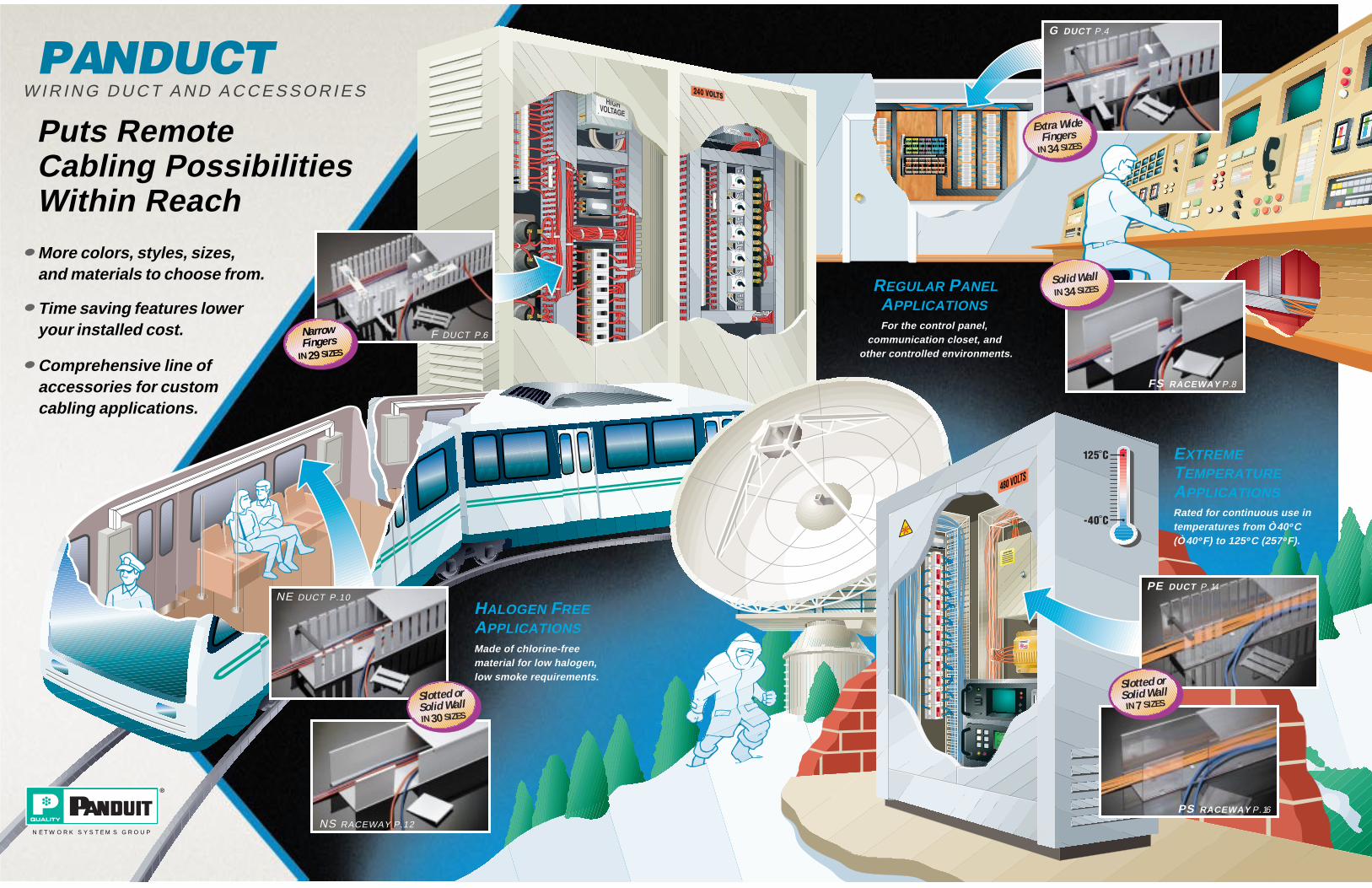
F DUCT P.6
NS RACEWAY P.12
NE DUCT P.10
FS RACEWAY P.8
G DUCT P.4
PS RACEWAY P.16
PE DUCT P.14
NarrowFingers
IN 29 SIZES
Slotted orSolid WallIN 30 SIZES
Solid WallIN 34 SIZES
Slotted orSolid Wall
IN 7 SIZES
Extra WideFingers
IN 34 SIZES
PANDUCTW I R I N G D U C T A N D A C C E S S O R I E S
Puts RemoteCabling PossibilitiesWithin Reach
HALOGEN FREEAPPLICATIONSMade of chlorine-freematerial for low halogen,low smoke requirements.
REGULAR PANELAPPLICATIONS For the control panel,
communication closet, and other controlled environments.
EXTREME TEMPERATUREAPPLICATIONSRated for continuous use intemperatures from Ò40 ° C(Ò40° F) to 125° C (257° F).
NETWORK SYSTEMS GROUP
More colors, styles, sizes,and materials to choose from.
Time saving features loweryour installed cost.
Comprehensive line ofaccessories for customcabling applications.

4 For Technical Assistance, call: 888-506-5400, Ext. 8287
PANDUCT ® Type G — Slotted Wall Wiring Duct
*Adhesive tape is not CSA Certified. See page 29 for complete listing of dimensions. ✔=New Sizes
Duct Part Number
Duct External Dimensions Cover Part
Number
DuctStd. Ctn.
Qty.
Cover Std. Ctn.
Qty.
Std.Lgth
WxH IN. WxH (mm)
G.5X.5LG6G.5X1LG6
0.69 x .560.69 x 1.09
(17.5) x (14.2)(17.5) x (27.1) C.5LG6 120 ft.
120 ft.120 ft.120 ft. 6 ft.
G.75X.75LG6G.75X1LG6G.75X1.5LG6G.75X2LG6
0.94 x 0.830.94 x 1.090.94 x 1.580.94 x 2.09
(23.9) x (21.0)(23.9) x (27.1)(23.9) x (40.0)(23.9) x (53.0)
C.75LG6
120 ft.120 ft.120 ft.120 ft.
120 ft.120 ft.120 ft.120 ft.
6 ft.
G1X1LG6G1X1.5LG6G1X2LG6G1X3LG6G1X4LG6
1.25 x 1.091.25 x 1.591.25 x 2.091.25 x 3.101.25 x 4.10
(31.8) x (27.1)(31.8) x (40.3)(31.8) x (53.0)(31.8) x (78.6)(31.8) x (104.0)
C1LG6
120 ft.120 ft.120 ft.120 ft.
60 ft.
120 ft.120 ft.120 ft.120 ft.120 ft.
6 ft.
G1.5X1 LG6G1.5X1.5LG6G1.5X2LG6G1.5X3LG6G1.5X4LG6
1.75 x 1.091.75 x 1.591.75 x 2.091.75 x 3.101.75 x 4.10
(44.5) x (27.1)(44.5) x (40.3)(44.5) x (53.0)(44.5) x (78.6)(44.5) x (104.0)
C1.5LG6
120 ft.120 ft.120 ft.120 ft.
60 ft.
120 ft.120 ft.120 ft.120 ft.120 ft.
6 ft.
G2X1 LG6G2X1.5LG6G2X2LG6G2X3LG6G2X4LG6G2X5LG6
2.25 x 1.092.25 x 1.592.25 x 2.092.25 x 3.102.25 x 4.102.25 x 5.11
(57.2) x (27.1)(57.2) x (40.3)(57.2) x (53.0)(57.2) x (78.6)(57.2) x (104.0)(57.2) x (129.7)
C2LG6
120 ft.120 ft.120 ft.
60 ft.60 ft.60 ft.
120 ft.120 ft.120 ft.120 ft.120 ft.120 ft.
6 ft.
G2.5X3LG6 2.75 x 3.12 (69.9) x (79.2) C2.5LG6 60 ft. 120 ft. 6 ft.
G3X1LG6G3X2LG6G3X3LG6G3X4LG6G3X5LG6
3.25 x 1.093.25 x 2.093.25 x 3.103.25 x 4.103.25 x 5.11
(82.6) x (27.6)(82.6) x (53.0)(82.6) x (78.6)(82.6) x (104.0)(82.6) x (129.7)
C3LG6
120 ft.120 ft.
60 ft.60 ft.60 ft.
120 ft.120 ft.120 ft.120 ft.120 ft.
6 ft.
G4X1.5LG6G4X2LG6G4X3LG6G4X4LG6G4X5LG6
4.25 x 1.584.25 x 2.094.25 x 3.104.25 x 4.104.25 x 5.11
(108.0) x (40.0)(108.0) x (53.0)(108.0) x (78.6)(108.0) x (104.0)(108.0) x (129.7)
C4LG6
60 ft.60 ft.60 ft.60 ft.60 ft.
120 ft.120 ft.120 ft.120 ft.120 ft.
6 ft.
G6X4LG6 6.25 x 4.11 (158.8) x (104.4) C6LG6 60 ft. 120 ft. 6 ft.
Ordering Information:• Order number of feet required in
multiples of 6 ft or Std. Carton quantities.
• To order duct without mounting holes, add NM to Part Number.
• To order with pressure-sensitive adhesive mounting tape applied, add -A to Part Number.
• Part Number shown for Light Gray LG. To order other colors, substi-tute WH for White, DG for Dark Gray, BL for Black, and IB for Intrinsic Blue
†See page 36 to determine which sizes are available in each color
Type G— Wiring Duct Standard Colors†:
Colors shown are approximate.
LG DG WHLight Gray Dark Gray White
BL IBBlack IntrinsicBlue
Part Number Nomenclature —
type/style nominal width (in)
colornominal height (in)
length (ft)
G .5 .5 LG 6X
Type G Slotted Wall Wiring Duct• Made of rigid PVC (See pg. 34 for material specifications)• Rated for continuous use temperatures up to 50°C (122°F)• U.L. Flammability Rating: V-0• Available in a variety of colors as a standard part†• Provided with standard mounting holes (dimensions see pg. 29)• Available without mounting holes (See ordering information
below)• Available with adhesive backing* (See page 22 for details)
✔✔
✔
✔
✔
✔
✔

5
Wide Fingers• Provide added support• Same slot and finger width as
Type E duct
Flush Cover with Base• Improves aesthetics• Provides greater wire capacity
Restricted Slot Design• Retains wire in slot• Speeds installation
—Simply deflect finger for fast, easy wire installation or removal
Optional Divider Walls• Can create multiple channels
within one duct to separate wiring
Exclusive Rounded Edges Along Entire Slot• Protect wires and hands from
abrasion
Non-Slip Cover Design• Incorporates integral high fric-
tion lining to inhibit cover move-ment
Easy Cover Removal• Changes to wiring can be made
quickly & easily
Double Scorelines• Upper Scoreline:
—Fingers break off leaving a smooth edge, without the use of a tool
• Lower Scoreline:—Fingers and sidewall break off
flush with base for junctions. (Use DNT-100 Tool to cut side wall)
Bar Coded Part Number Label with QC Number• Allows for automated inventory
control systems• Quick identification of loose
piece wiring duct• Complete Quality Traceability
Optional Pressure-Sensitive Adhesive Mounting Tape
Restricted Slot
Double Scoreline
Extra Wide Fingers
Exclusive Rounded Edges
Non-Slip Cover
Flush Sidewall
Accessories
Duct Cutting Tool ..............................23Duct Finger Notching Tool ...............23Nylon Rivet Installation Tool ............23Divider Walls......................................24Wire Retainers...................................25Optional Mounting Clip.....................27Labeling .............................................28
Features & Benefits
Choose from 34 sizes of PanduitType G Wiring Duct; from 0.5" x 0.5"up to 6" x 4" . Used for general pur-pose control panel wiring and to routeand protect wiring in communicationclosets. The non-slip cover concealsall wiring and is easy to install. Theduct and cover form a flush sidewallproviding increased capacity and im-proved aesthetics.
Type G Slotted Wall Wiring Duct

6 For Technical Assistance, call: 888-506-5400, Ext. 8287
PANDUCT ® Type F — Slotted Wall Wiring Duct
Type F— Wiring Duct Standard Colors†:
Colors shown are approximate.
LG WHLight Gray White
Part Number Nomenclature —
type/style color length (ft)
F .5 .5 LG 6X
Type F Slotted Wall Wiring Duct• Made of rigid PVC (See pg. 34 for material specifications)• Rated for continuous use temperatures up to 50°C (122°F)• U.L. Flammability Rating: V-0• Available in a Light Gray and White color†• Provided with standard mounting holes (dimensions see pg. 30 )• Available without mounting holes (See ordering information
below)• Available with adhesive backing* (See page 22 for details)
nominal width (in)
nominal height (in)
Ordering Information:• Order number of feet required in
multiples of 6 ft or Std. Carton quantities.
• To order duct without mounting holes, add NM to Part Number.
• To order with pressure-sensitive adhesive mounting tape applied, add -A to Part Number.
• Part Number shown for Light Gray LG. To order other colors, substi-tute WH White, DG Dark Gray, BL Black, and IB Intrinsic Blue
†See page 36 to determine which sizes are available in each color
*Adhesive tape is not CSA Certified.See page 30 for complete listing of dimensions. ✔=New Sizes
Duct Part Number
Duct External Dimensions Cover Part
Number
DuctStd. Ctn.
Qty.
Cover Std. Ctn.
Qty.
Std.Lgth
WxH IN. WxH (mm)
F.5X.5LG6F.5X1LG6
0.69 x 0.560.69 x 1.09
(17.5) x (14.2)(17.5) x (27.1) C.5LG6 120 ft.
120 ft.120 ft.120 ft. 6 ft.
F.75X.75LG6F.75X1.5LG6
0.94 x 0.830.94 x 1.58
(23.9) x (21.0)(23.9) x (40.0) C.75LG6 120 ft.
120 ft.120 ft.120 ft. 6 ft.
F1X1LG6F1X1.5LG6F1X2LG6F1X3LG6F1X4LG6
1.25 x 1.091.25 x 1.591.25 x 2.091.25 x 3.101.25 x 4.10
(31.8) x (27.1)(31.8) x (40.3)(31.8) x (53.0)(31.8) x (78.6)(31.8) x (104.0)
C1LG6
120 ft.120 ft.120 ft.120 ft.
60 ft.
120 ft.120 ft.120 ft.120 ft.120 ft.
6 ft.
F1.5X1 LG6F1.5X1.5LG6F1.5X2LG6F1.5X3LG6F1.5X4LG6
1.75 x 1.091.75 x 1.591.75 x 2.091.75 x 3.101.75 x 4.10
(44.5) x (27.1)(44.5) x (40.3)(44.5) x (53.0)(44.5) x (78.6)(44.5) x (104.0)
C1.5LG6
120 ft.120 ft.120 ft.120 ft.
60 ft.
120 ft.120 ft.120 ft.120 ft.120 ft.
6 ft.
F2X1 LG6F2X1.5LG6F2X2LG6F2X3LG6F2X4LG6F2X5LG6
2.25 x 1.092.25 x 1.592.25 x 2.092.25 x 3.102.25 x 4.102.25 x 5.11
(57.2) x (27.1)(57.2) x (40.3)(57.2) x (53.0)(57.2) x (78.6)(57.2) x (104.0)(57.2) x (129.7)
C2LG6
120 ft.120 ft.120 ft.
60 ft.60 ft.60 ft.
120 ft.120 ft.120 ft.120 ft.120 ft.120 ft.
6 ft.
F3X1LG6F3X2LG6F3X3LG6F3X4LG6F3X5LG6
3.25 x 1.093.25 x 2.093.25 x 3.103.25 x 4.103.25 x 5.11
(82.6) x (27.6)(82.6) x (53.0)(82.6) x (78.6)(82.6) x (104.1)(82.6) x (129.8)
C3LG6
120 ft.120 ft.
60 ft.60 ft.60 ft.
120 ft.120 ft.120 ft.120 ft.120 ft.
6 ft.
F4X2LG6F4X3LG6F4X4LG6F4X5LG6
4.25 x 2.094.25 x 3.104.25 x 4.104.25 x 5.11
(108.0) x (53.0)(108.0) x (78.6)(108.0) x (104.1)(108.0) x (129.8)
C4LG6
60 ft.60 ft.60 ft.60 ft.
120 ft.120 ft.120 ft.120 ft.
6 ft.
✔
✔
✔✔
✔✔
✔✔

7
Narrow Fingers• Less “fanning” of wires for a neater appearance
• Provides the proper spacing for use with high density terminal blocks
Restricted Slot Design• Retains wire in slot• Speeds installation• Simply deflect finger for fast, easy wire installation orremoval
Double Restricted Slot On Larger Sizes• Retains wires in top or bottom slot
• Speeds installation
Flush Cover with Base• Improves aesthetics• Provides greater wire capacity
Optional Divider Wall• Can create multiple channels within one duct to separate wiring
Exclusive Rounded Edges Along Entire Slot• Protect wires and hands from abrasion
Non-Slip Cover Design• Incorporates integral high fric-tion lining to inhibit cover move-ment
Easy Cover Removal• Changes to wiring can be made quickly & easily
Double Scorelines• Upper Scoreline:
—Fingers break off leaving a smooth edge, without the use of a tool
• Lower Scoreline:—Fingers and sidewall break off
flush with base for junctions. (Use DNT-100 Tool to cut side wall)
Bar Coded Part Number Label with QC Number• Allows for automated inventory control systems
• Quick identification of loose piece duct
• Complete Quality Traceability
Optional Pressure-Sensitive Adhesive Mounting Tape
Narrow Fingers
Double Restricted Slot
Double Scoreline
Exclusive Rounded Edges
Non-SlipCover
Flush Sidewall
Features & Benefits
Accessories
Duct Cutting Tool ..............................23Duct Finger Notching Tool ...............23Nylon Rivet Installation Tool ............23Divider Walls......................................24Wire Retainers...................................25Optional Mounting Clip.....................27Labeling .............................................28
Choose from 29 sizes of PanduitType F Wiring Duct; from .5" x .5" upto 4" x 5". Used for general purposecontrol panel wiring and to route andprotect wiring in communication clos-ets. Ideal for use with high densityterminal blocks. The non-slip coverconceals all wiring and is easy to in-stall. The duct and cover form a flushsidewall providing increased capacityand improved aesthetics.
Type F Slotted Wall Wiring Duct

8 For Technical Assistance, call: 888-506-5400, Ext. 8287
PANDUCT ® Type FS — Solid Wall Raceway
Part Number Nomenclature —
type/style color length (ft)
FS .5 .5 LG 6X
Type FS Solid Wall Raceway• Made of rigid PVC (See pg. 34 for material specifications)• Rated for continuous use temperatures up to 50°C (122°F)• U.L. Flammability Rating: V-0• Available in a variety of colors as a standard part†• Supplied without mounting holes • Available with mounting holes (See ordering information below)• Available with adhesive backing* (See page 22 for details)
nominal width (in)
nominal height (in)
*Adhesive tape is not CSA Certified. See page 30 for complete listing of dimensions. ✔=New Sizes
Raceway Part Number
Raceway External Dimensions Cover Part
Number
RacewayStd. Ctn.
Qty.
Cover Std. Ctn.
Qty.
Std.Lgth
WxH IN. WxH (mm)
FS.5X.5LG6NMFS.5X1LG6NM
0.69 x 0.560.69 x 1.09
(17.5) x(14.2)(17.5) x (27.1)
C.5LG6 120 ft.120 ft.
120 ft.120 ft.
6 ft.
FS.75X.75LG6NMFS.75X1LG6NMFS.75X1.5LG6NMFS.75X2LG6NM
0.94 x 0.830.94 x 1.090.94 x 1.580.94 x 2.09
(23.9) x (21.0)(23.9) x (27.1)(23.9) x (40.0)(23.9) x (53.0)
C.75LG6
120 ft.120 ft.120 ft.120 ft.
120 ft.120 ft.120 ft.120 ft.
6 ft.
FS1X1LG6NMFS1X1.5LG6NMFS1X2LG6NMFS1X3LG6NMFS1X4LG6NM
1.25 x 1.091.25 x 1.591.25 x 2.091.25 x 3.101.25 x 4.10
(31.8) x (27.1)(31.8) x (40.3)(31.8) x (53.0)(31.8) x (78.6)(31.8) x (104.0)
C1LG6
120 ft.120 ft.120 ft.120 ft.
60 ft.
120 ft.120 ft.120 ft.120 ft.120 ft.
6 ft.
FS1.5X1 LG6NMFS1.5X1.5LG6NMFS1.5X2LG6NMFS1.5X3LG6NMFS1.5X4LG6NM
1.75 x 1.091.75 x 1.591.75 x 2.091.75 x 3.101.75 x 4.10
(44.5) x (27.1)(44.5) x (40.3)(44.5) x (53.0)(44.5) x (78.6)(44.5) x (104.0)
C1.5LG6
120 ft.120 ft.120 ft.120 ft.
60 ft.
120 ft.120 ft.120 ft.120 ft.120 ft.
6 ft.
FS2X1 LG6NMFS2X1.5LG6NMFS2X2LG6NMFS2X3LG6NMFS2X4LG6NMFS2X5LG6NM
2.25 x 1.092.25 x 1.592.25 x 2.092.25 x 3.102.25 x 4.102.25 x 5.11
(57.2) x (27.1)(57.2) x (40.3)(57.2) x (53.0)(57.2) x (78.6)(57.2) x (104.0)(57.2) x (129.7)
C2LG6
120 ft.120 ft.120 ft.
60 ft.60 ft.60 ft.
120 ft.120 ft.120 ft.120 ft.120 ft.120 ft.
6 ft.
FS2.5X3LG6NM 2.75 x 3.12 (69.9) x (79.2) C2.5LG6 60 ft. 120 ft. 6 ft.
FS3X1LG6NMFS3X2LG6NMFS3X3LG6NMFS3X4LG6NMFS3X5LG6NM
3.25 x 1.093.25 x 2.093.25 x 3.103.25 x 4.103.25 x 5.11
(82.6) x (27.6)(82.6) x (53.0)(82.6) x (78.6)(82.6) x (104.0)(82.6) x (129.7)
C3LG6
120 ft.120 ft.
60 ft.60 ft.60 ft.
120 ft.120 ft.120 ft.120 ft.120 ft.
6 ft.
FS4X1.5LG6NMFS4X2LG6NMFS4X3LG6NMFS4X4LG6NMFS4X5LG6NM
4.25 x 1.584.25 x 2.094.25 x 3.104.25 x 4.104.25 x 5.11
(108.0) x (40.0)(108.0) x (53.0)(108.0) x (78.6)(108.0) x (104.0)(108.0) x (129.7)
C4LG6
60 ft.60 ft.60 ft.60 ft.
120 ft.120 ft.120 ft.120 ft.
6 ft.
FS6X4LG6NM 6.25 x 4.11 (158.8) x (104.4) C6LG6 60 ft. 120 ft. 6 ft.
NM
no mounting holes
Type FS— Wiring Duct Standard Colors†:
Colors shown are approximate.
LG DG WH
Light Gray Dark Gray White
BL IB
Black IntrinsicBlue
Ordering Information:• Order number of feet required in
multiples of 6 ft or Std. Carton quantities.
• To order duct with mounting holes, delete NM from Part Number.
• To order with pressure-sensitive adhesive mounting tape applied, add -A to Part Number.
• Part Number shown for Light Gray LG. To order other colors, substi-tute WH for White, DG for Dark Gray, BL for Black, and IB for Intrinsic Blue
†See page 36 to determine which sizes are available in each color
✔
✔
✔
✔

9
Solid Walls• Provide maximum wire
protection
Flush Cover With Base• Improves aesthetics
Larger Internal Area• Provides greater wire capacity
Non-Slip Cover Design• Incorporates integral high
friction lining to inhibit cover movement
Optional Divider Wall• Can create multiple channels
within one duct to separate wiring
Easy Cover Installation and Removal• Changes to wiring can be made
quickly & easily
Scoreline at Base of Wall• Allows for a breakout which is
flush with base of the duct
Optional Mounting Holes• Has same mounting hole pat-
tern as Type F Duct
Bar Coded Part Number Label with QC Number• Allows for automated inventory
control systems• Quick identification of loose
piece duct• Complete Quality Traceability
Optional Pressure-Sensitive Adhesive Mounting Tape
Non-Slip Cover
Scoreline at Base
Cuts easily with DCT Tool
Optional Divider Wall
Solid Wall Design
Flush Sidewall
Features & Benefits
Accessories
Duct Cutting Tool ..............................23Duct Finger Notching Tool ...............23Nylon Rivet Installation Tool ............23Divider Walls......................................24Wire Retainers...................................25Optional Mounting Clip.....................27Labeling .............................................28
Choose from 34 sizes of Panduit TypeFS Solid Wall Raceway from .5"x.5' upto 6"x4" . The PVC material can be eas-ily cut for breakouts and junctions. Thenon-slip cover keeps all wiring in placeand is easy to install. The cover andbase form a flush sidewall for increasedcapacity and improved aesthetics. It isexcellent for use in non-plenum applica-tions including under floor and telecom-munication closet installations.
Type FS Solid Wall Raceway

10 For Technical Assistance, call: 888-506-5400, Ext. 8287
PANDUCT® Type NE — Halogen Free Slotted Wall Wiring Duct
Type NE— Wiring Duct Standard Colors†:
Colors shown are approximate.
LG WHLight Gray White
Type NE — Halogen Free Slotted Wall Wiring Duct• Made of Halogen free material (See page 34 for
material specifications)• Rated for continuous use temperatures -40°C (-40°F) up to
95°C (203°F) • Available in Light Gray and White color†• Provided with standard mounting holes (dimensions see pg. 31)• Available without mounting holes (See ordering info below)• Available with adhesive backing* (See page 22 for details)
Ordering Information:• Order number of feet required in
multiples of 6 ft or Std. Carton quantities.
• To order duct without mounting holes, add NM to Part Number.
• To order with pressure-sensitive adhesive mounting tape applied, add -A to Part Number.
• Part Number shown for Light Gray LG. To order other color, substi-tute WH White
†See page 36 to determine which sizes are available in each color
NOTE: Avoid the use of screw tap and set fluids around “halogen free” material. These agents may cause material to become brittle. *Adhesive tape is not CSA Certified.>Available as a standard part in WH color only.See page 31 for complete listing of dimensions.
Duct Part Number
Duct Ext.ernal Dimensions Cover Part
Number
DuctStd. Ctn.
Qty.
Cover Std. Ctn.
Qty.
Std.Lgth
WxH IN. WxH (mm)
NE.5X.5WH6NE.5X.62LG6NE.5X1LG6NE.5X1.25LG6NE.5X1.75LG6
0.63 x 0.560.63 x 0.680.63 x 1.060.63 x 1.310.63 x 1.81
(16.0) x (14.2)(16.0) x (17.3)(16.0) x (26.9)(16.0) x (33.3)(16.0) x (46.0)
NC.5LG6
120 ft.120 ft.120 ft.120 ft.120 ft.
120 ft.120 ft.120 ft.120 ft.120 ft.
6 ft.
NE1X1LG6NE1X1.5LG6NE1X2LG6NE1X3LG6NE1X4LG6
1.14 x 1.121.14 x 1.621.14 x 2.121.14 x 3.121.14 x 4.12
(29.0) x (28.4)(29.0) x (41.1)(29.0) x (53.8)(29.0) x (79.2)(29.0) x (104.6)
NC1LG6
120 ft.120 ft.120 ft.120 ft.120 ft.
120 ft.120 ft.120 ft.120 ft.120 ft.
6 ft.
NE1.5X1WH6NE1.5X1.5LG6NE1.5X2LG6NE1.5X3LG6NE1.5X4LG6
1.64 x 1.121.64 x 1.621.64 x 2.121.64 x 3.121.64 x 4.12
(41.7) x (28.4)(41.7) x (41.1)(41.7) x (53.8)(41.7) x (79.2)(41.7) x (104.6)
NC1.5LG6
120 ft.120 ft.120 ft.120 ft.
60 ft.
120 ft.120 ft.120 ft.120 ft.120 ft.
6 ft.
NE2X1LG6NE2X1.5WH6NE2X2LG6NE2X3LG6NE2X4LG6
2.14 x 1.122.14 x 1.622.14 x 2.122.14 x 3.122.14 x 4.12
(54.4) x (28.4)(54.4) x (41.1)(54.4) x (53.8)(54.4) x (79.2)(54.4) x (104.6)
NC2LG6
120 ft.120 ft.120 ft.
60 ft.60 ft.
120 ft.120 ft.120 ft.120 ft.120 ft.
6 ft.
NE2.5X3LG6 2.64 x 3.12 (67.1) x (79.2) NC2.5LG6 60 ft. 120 ft. 6 ft.
NE3X1LG6NE3X2LG6NE3X3LG6NE3X4LG6NE3X5LG6
3.14 x 1.123.14 x 2.123.14 x 3.123.14 x 4.123.14 x 5.12
(79.8) x (28.4)(79.8) x (53.8)(79.8) x (79.2)(79.8) x (104.6)(79.8) x (130.0)
NC3LG6
120 ft.120 ft.
60 ft.60 ft.60 ft.
120 ft.120 ft.120 ft.120 ft.120 ft.
6 ft.
NE4X2LG6NE4X3LG6NE4X4LG6NE4X5LG6
4.14 x 2.124.14 x 3.124.14 x 4.124.14 x 5.12
(105.2) x (53.8)(105.2) x (79.2)(105.2) x (104.6)(105.2) x (130.0)
NC4LG6
60 ft.60 ft.60 ft.60 ft.
120 ft.120 ft.120 ft.120 ft.
6 ft.
Part Number Nomenclature —
type/style color length (ft)
NE .5 .62 LG 6X
nominal width (in)
nominal height (in)
>
>
>

11
Halogen Free Material• Made of chlorine-free material
for low halogen requirements
Increased Temperature Resistance• Rated for temperatures from
-40°C (-40°F) up to 95°C (203°F)
Restricted Slot Design• Retains wire in slot• Speeds installation• Simply deflect finger for fast,
easy wire installation orremoval
Exclusive Rounded Edges Along Entire Slot• Protect wires and hands from
abrasion
Non-Slip Cover Design• Incorporates integral high fric-
tion lining to inhibit cover movement
Easy Cover Removal• Changes to wiring can be made
quickly & easily
Bar Coded Part Number Label with QC Number• Allows for automated inventory
control systems• Quick identification of loose
piece duct• Complete Quality Traceability
Optional Pressure-Sensitive Adhesive Mounting Tape
Restricted Slot
Wide Fingers
Exclusive Rounded Edges
Non-Slip Cover
Scoreline at Base
Halogen Free Material
Features & Benefits
Accessories
Duct Cutting Tool ..............................23Duct Finger Notching Tool ...............23Nylon Rivet Installation Tool ............23Wire Retainers...................................25Optional Mounting Clip.....................27Labeling .............................................28
Choose from 30 sizes of PanduitType NE Halogen Free Slotted WallWiring Duct from .5"x.5" up to4"x5" . The Halogen free material al-lows the duct to be used in highertemperature environments, to 95°C(203°F), and low temperature envi-ronments, to -40°C (-40°F). The non-slip cover keeps all wiring in placeand is easy to install. The materialcan be easily cut for breakouts andjunctions using the DCT and DNTtools.
Type NE Slotted Wall Wiring Duct

12 For Technical Assistance, call: 888-506-5400, Ext. 8287
Type NS— RacewayStandard Colors†:
Colors shown are approximate.
LG WHLight Gray White
Type NS—Halogen Free Solid Wall Raceway• Made of Halogen free material (See page 34 for
material specifications)• Rated for continuous use temperatures -40°C (-40°F) up to
95°C (203°F) • Available in Light Gray and White color†• Provided without standard mounting holes (dims see pg. 31)• Available with mounting holes (See ordering info below)• Available with adhesive backing* (See page 22 for details)
Ordering Information:• Order number of feet required in
multiples of 6 ft or Std. Carton quantities.
• To order duct with mounting holes, delete NM to Part Number.
• To order with pressure-sensitive adhesive mounting tape applied, add -A to Part Number.
• art Number shown for Light Gray LG. To order other color, substi-tute WH White
†See page 36 to determine which sizes are available in each color
NOTE: Avoid the use of screw tap and set fluids around “halogen free” material. These agents may cause material to become brittle. *Adhesive tape is not CSA Certified. >Available as a standard part in WH color only.See page 31 for complete listing of dimensions.
Raceway Part Number
Raceway External Dimensions Cover Part
Number
RacewayStd. Ctn.
Qty.
Cover Std. Ctn.
Qty.
Std.Lgth
WxH IN. WxH (mm)
NS.5X.5WH6NMNS.5X.62LG6NMNS.5X1LG6NMNS.5X1.25LG6NMNS.5X1.75LG6NM
0.63 x 0.560.63 x 0.680.63 x 1.060.63 x 1.310.63 x 1.81
(16.0) x (14.2)(16.0) x (17.3)(16.0) x (26.9)(16.0) x (33.3)(16.0) x (46.0)
NC.5LG6
120 ft.120 ft.120 ft.120 ft.120 ft.
120 ft.120 ft.120 ft.120 ft.120 ft.
6 ft.
NS1X1LG6NMNS1X1.5LG6NMNS1X2LG6NMNS1X3LG6NMNS1X4LG6NM
1.14 x 1.121.14 x 1.621.14 x 2.121.14 x 3.121.14 x 4.12
(29.0) x (28.4)(29.0) x (41.1)(29.0) x (53.8)(29.0) x (79.2)(29.0) x (104.6)
NC1LG6
120 ft.120 ft.120 ft.120 ft.120 ft.
120 ft.120 ft.120 ft.120 ft.120 ft.
6 ft.
NS1.5X1WH6NMNS1.5X1.5LG6NMNS1.5X2LG6NMNS1.5X3LG6NMNS1.5X4LG6NM
1.64 x 1.121.64 x 1.621.64 x 2.121.64 x 3.121.64 x 4.12
(41.7) x (28.4)(41.7) x (41.1)(41.7) x (53.8)(41.7) x (79.2)(41.7) x (104.6)
NC1.5LG6
120 ft.120 ft.120 ft.120 ft.
60 ft.
120 ft.120 ft.120 ft.120 ft.120 ft.
6 ft.
NS2X1LG6NMNS2X1.5WH6NMNS2X2LG6NMNS2X3LG6NMNS2X4LG6NM
2.14 x 1.122.14 x 1.622.14 x 2.122.14 x 3.122.14 x 4.12
(54.4) x (28.4)(54.4) x (41.1)(54.4) x (53.8)(54.4) x (79.2)(54.4) x (104.6)
NC2LG6
120 ft.120 ft.120 ft.
60 ft.60 ft.
120 ft.120 ft.120 ft.120 ft.120 ft.
6 ft.
NS2.5X3LG6NM 2.64 x 3.12 (67.1) x (79.2) NC2.5LG6 60 ft. 120 ft. 6 ft.
NS3X1LG6NMNS3X2LG6NMNS3X3LG6NMNS3X4LG6NMNS3X5LG6NM
3.14 x 1.123.14 x 2.123.14 x 3.123.14 x 4.123.14 x 5.12
(79.8) x (28.4)(79.8) x (53.8)(79.8) x (79.2)(79.8) x (104.6)(79.8) x (130.0)
NC3LG6
120 ft.120 ft.
60 ft.60 ft.60 ft.
120 ft.120 ft.120 ft.120 ft.120 ft.
6 ft.
NS4X2LG6NMNS4X3LG6NMNS4X4LG6NMNS4X5LG6NM
4.14 x 2.124.14 x 3.124.14 x 4.124.14 x 5.12
(105.2) x (53.8)(105.2) x (79.2)(105.2) x (104.6)(105.2) x (130.0)
NC4LG6
60 ft.60 ft.60 ft.60 ft.
120 ft.120 ft.120 ft.120 ft.
6 ft.
Part Number Nomenclature —
type/style color length (ft)
NS .5 .62 LG 6X
nominal width (in)
nominal height (in)
NM
no mounting holes
PANDUCT ® Type NS — Halogen Free Solid Wall Raceway
>
>
>

13
Halogen Free Material• Made of chlorine-free material
for low halogen, requirements
Increased Temperature Resistance• Rated for temperatures from
-40°C (-40°F) up to 95°C (203°F)
Solid Walls• Provide maximum wire
protection
Non-Slip Cover Design• Incorporates integral high
friction lining to inhibit cover movement
Larger Internal Area• Provides greater wire capacity
Easy Cover Installation and Removal• Changes to wiring can be made
quickly & easily
Bar Coded Part Number Label with QC Number• Allows for automated inventory
control systems• Quick identification of loose
piece duct• Complete Quality Traceability
Optional Pressure-Sensitive Adhesive Mounting Tape
Non-Slip Cover
Scoreline at Base
Cuts easily with DCT Tool
Solid Wall DesignHalogen Free Material
Features & Benefits
Accessories
Duct Cutting Tool ..............................23Duct Finger Notching Tool ...............23Nylon Rivet Installation Tool ............23Wire Retainers...................................25Optional Mounting Clip.....................27Labeling .............................................28
Choose from 30 sizes of PanduitType NS Halogen Free Solid WallRaceway from .5"x.5" up to 4"x5" .The Halogen free material allows theduct to be used in higher temperatureenvironments, to 95°C (203°F), andlow temperature environments, to -40°C (-40°F). The non-slip coverkeeps all wiring in place and is easyto install. The material can be easilycut for breakouts and junctions usingthe DCT and DNT tools.
Type NS Solid Wall Raceway

14 For Technical Assistance, call: 888-506-5400, Ext. 8287
PANDUCT® Type PE — Polycarbonate Slotted Wall Wiring Duct
Type PE— Wiring DuctStandard Colors†:
CL
Clear
Type PE—Polycarbonate Slotted Wall Wiring Duct• Made of Polycarbonate material—for low halogen, low smoke
applications (see page 34 for material specifications)• Rated for continuous use temperatures up to 125°C (257°F) • Available in clear only• Provided with standard mounting holes (dims see pg. 31)• Available without mounting holes (See ordering info below)• Available with adhesive backing* (See page 22 for details)
Ordering Information:• Order number of feet required in
multiples of 6 ft or Std. Carton quantities.
• To order duct without mounting holes, add NM to Part Number.
• To order with pressure-sensitive adhesive mounting tape applied, add -A to Part Number.
• Part Number shown for CL Clear
†Available in Clear only
Polycarbonate raceway is not UL Recognized or CSA Certified>For availability contact factory. *Adhesive tape is not CSA Certified. See page 31 for complete listing of dimensions.
Duct Part Number
Duct Ext.ernal Dimensions Cover Part
Number
Std. Ctn.Qty.
Std. Ctn.Qty.
Std.Lgth
WxH IN. WxH (mm)
PE.75X1CL6 0.88 x 1.06 (22.4) x (26.9) PC.75CL6 120 ft. 120 ft. 6 ft.
PE1X2CL6 1.14 x 2.12 (29.0) x (53.8) PC1CL6 120 ft. 120 ft. 6 ft.
PE1X3CL6 1.14 x 3.12 (29.0) x (79.2) PC1CL6 120 ft. 120 ft. 6 ft.
PE1.5X1.5CL6 1.64 x 1.62 (41.7) x (41.1) PC1.5CL6 120 ft. 120 ft. 6 ft.
PE2X1.5CL6PE2X2CL6
2.14 x 1.622.14 x 2.12
(54.4) x (41.1)(54.4) x (53.8) PC2CL6 120 ft. 120 ft. 6 ft.
PE3X1.25CL6 3.14 x 1.37 (79.8) x (34.8) PC3CL6 120 ft. 120 ft. 6 ft.
PE4X4CL6 4.14 x 4.12 (105.2) x (104.6) PC4CL6 60 ft. 120 ft. 6 ft.
Part Number Nomenclature —
type/style color length (ft)
PE .75 1 CL 6X
nominal height (in)
nominal width (in)
>>

15
Low Halogen, Low Smoke Material• Made from low halogen, low
smoke Polycarbonate material
Increased Temperature Resistance• Rated for temperatures from
-40°C (-40°F) up to 125°C (257°F)
Restricted Slot Design• Retains wire in slot• Speeds installation• Simply deflect finger for fast,
easy wire installation orremoval
Exclusive Rounded Edges Along Entire Slot• Protect wires and hands from
abrasion
Optional Divider Wall• Can create multiple channels
within one duct to separatewiring
Easy Cover Removal• Changes to wiring can be made
quickly & easily
Bar Coded Part Number Label with QC Number• Allows for automated inventory
control systems• Quick identification of loose
piece duct• Complete Quality Traceability
Optional Pressure-Sensitive Adhesive Mounting Tape
Accessories
Duct Cutting Tool ..............................23Duct Finger Notching Tool ...............23Nylon Rivet Installation Tool ............23Divider Walls......................................24Wire Retainers...................................25Optional Mounting Clip.....................27Labeling .............................................28
Scoreline at Base
Low Halogen, Low Smoke Material
Wide Fingers
Exclusive Rounded Edges
Restricted Slot
Cuts easily with DCT Tool
Choose from 8 sizes of Panduit TypePE Polycarbonate Slotted Wall Wir-ing Duct from .75"x1" up to 4"x4" .The low halogen, low smoke Polycar-bonate material allows the duct to beused in higher temperature environ-ments, up to 125°C (257°F), and lowtemperature environments, to -40°C(-40°F). The material can be easilycut for breakouts and junctions usingthe DCT and DNT tools.
Type PE Polycarbonate Slotted Wall Duct Features & Benefits

16 For Technical Assistance, call: 888-506-5400, Ext. 8287
PANDUCT ® Type PS — Polycarbonate Solid Wall Raceway
Type PS— RacewayStandard Colors†:
CL
Clear
Type PS—Polycarbonate Solid Wall Raceway• Made of Polycarbonate material—for low halogen, low smoke
applications (see page 34 for material specifications)• Rated for continuous use temperatures up to 125°C (257°F) • Available in clear only• Provided with standard mounting holes (dims see pg. 31)• Available without mounting holes (See ordering info below)• Available with adhesive backing* (See page 22 for details)
Ordering Information:• Order number of feet required in
multiples of 6 ft or Std. Carton quantities.
• To order with mounting holes, delete NM to Part Number.
• To order with pressure-sensitive adhesive mounting tape applied, add -A to Part Number.
• Part Number shown for CL Clear
†Available in Clear only.
Polycarbonate raceway is not UL Recognized or CSA Certified*Adhesive tape is not CSA Certified. See page 31 for complete listing of dimensions.
Raceway Part Number
Raceway Ext.ernal Dimensions Cover Part
Number
RacewayStd. Ctn.
Qty.
Cover Std. Ctn.
Qty.
Std.Lgth
WxH IN. WxH (mm)
PS.75X1CL6NM 0.88 x 1.06 (22.4) x(26.9) PC.75CL6 120 ft. 120 ft. 6 ft.
PS1.5X1.5CL6NM 1.64 x 1.62 (41.7) x(41.1) PC1.5CL6 120 ft. 120 ft. 6 ft.
PS2X1.5CL6NMPS2X2CL6NM
2.14 x 1.622.14 x 2.12
(54.4) x(41.1)(54.4) x(53.8) PC2CL6 120 ft. 120 ft. 6 ft.
PS3X1.25CL6NM 3.14 x 1.37 (79.8) x(34.8) PC3CL6 120 ft. 120 ft. 6 ft.
PS4X4CL6NM 4.14 x 4.12 (105.2) x(104.6) PC4CL6 60 ft. 120 ft. 6 ft.
Part Number Nomenclature —
type/style color length (ft)
PS .75 1 CL 6X
nominal width (in)
nominal height (in)
NM
no mounting holes

17
Low Halogen, Low Smoke Material• Made from low halogen, low
smoke Polycarbonate material
Increased Temperature Resistance• Rated for temperatures up to
125°C (257°F)
Solid Walls• Provide maximum wire
protection
Larger Internal Area• Provides greater wire capacity
Optional Divider Wall• Can create multiple channels
within one duct to separate wiring
Easy Cover Installation and Removal• Changes to wiring can be made
quickly & easily
Bar Coded Part Number Label with QC Number• Allows for automated inventory
control systems
• Quick identification of loose piece duct
• Complete Quality Traceability
Optional Pressure-Sensitive Adhesive Mounting Tape
Features & Benefits
Choose from 6 sizes of Panduit TypePS Polycarbonate Solid Wall Race-way from .75"x1" up to 4"x4" . Thelow halogen, low smoke Polycarbon-ate material allows the raceway to beused in higher temperature environ-ments, up to 125°C (257°F), and lowtemperature environments, to -40°C(-40°F). The material can be easilycut for breakouts and junctions usingthe DCT and DNT tools.
Accessories
Duct Cutting Tool ..............................23Duct Finger Notching Tool ...............23Nylon Rivet Installation Tool ............23Divider Walls......................................24Wire Retainers...................................25Optional Mounting Clip.....................27Labeling .............................................28
Scoreline at Base
Low Halogen, Low Smoke Material
Type PS Polycarbonate Solid Wall Raceway
18 For Technical Assistance, call: 888-506-5400, Ext. 8287
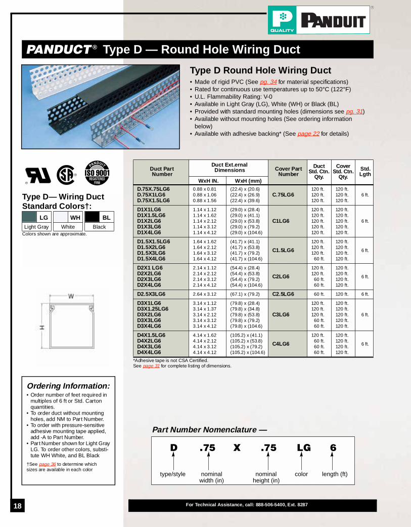
PANDUCT ® Type D — Round Hole Wiring Duct
*Adhesive tape is not CSA Certified.See page 31 for complete listing of dimensions.
Duct Part Number
Duct Ext.ernal Dimensions Cover Part
Number
DuctStd. Ctn.
Qty.
Cover Std. Ctn.
Qty.
Std.Lgth
WxH IN. WxH (mm)
D.75X.75LG6D.75X1LG6D.75X1.5LG6
0.88 x 0.810.88 x 1.060.88 x 1.56
(22.4) x (20.6)(22.4) x (26.9)(22.4) x (39.6)
C.75LG6120 ft.120 ft.120 ft.
120 ft.120 ft.120 ft.
6 ft.
D1X1LG6D1X1.5LG6D1X2LG6D1X3LG6D1X4LG6
1.14 x 1.121.14 x 1.621.14 x 2.121.14 x 3.121.14 x 4.12
(29.0) x (28.4)(29.0) x (41.1)(29.0) x (53.8)(29.0) x (79.2)(29.0) x (104.6)
C1LG6
120 ft.120 ft.120 ft.120 ft.120 ft.
120 ft.120 ft.120 ft.120 ft.120 ft.
6 ft.
D1.5X1.5LG6D1.5X2LG6D1.5X3LG6D1.5X4LG6
1.64 x 1.621.64 x 2.121.64 x 3.121.64 x 4.12
(41.7) x (41.1)(41.7) x (53.8)(41.7) x (79.2)(41.7) x (104.6)
C1.5LG6
120 ft.120 ft.120 ft.
60 ft.
120 ft.120 ft.120 ft.120 ft.
6 ft.
D2X1 LG6D2X2LG6D2X3LG6D2X4LG6
2.14 x 1.122.14 x 2.122.14 x 3.122.14 x 4.12
(54.4) x (28.4)(54.4) x (53.8)(54.4) x (79.2)(54.4) x (104.6)
C2LG6
120 ft.120 ft.
60 ft.60 ft.
120 ft.120 ft.120 ft.120 ft.
6 ft.
D2.5X3LG6 2.64 x 3.12 (67.1) x (79.2) C2.5LG6 60 ft. 120 ft. 6 ft.
D3X1LG6D3X1.25LG6D3X2LG6D3X3LG6D3X4LG6
3.14 x 1.123.14 x 1.373.14 x 2.123.14 x 3.123.14 x 4.12
(79.8) x (28.4)(79.8) x (34.8)(79.8) x (53.8)(79.8) x (79.2)(79.8) x (104.6)
C3LG6
120 ft.120 ft.120 ft.
60 ft.60 ft.
120 ft.120 ft.120 ft.120 ft.120 ft.
6 ft.
D4X1.5LG6D4X2LG6D4X3LG6D4X4LG6
4.14 x 1.624.14 x 2.124.14 x 3.124.14 x 4.12
(105.2) x (41.1)(105.2) x (53.8)(105.2) x (79.2)(105.2) x (104.6)
C4LG6
120 ft.60 ft.60 ft.60 ft.
120 ft.120 ft.120 ft.120 ft.
6 ft.
Ordering Information:• Order number of feet required in
multiples of 6 ft or Std. Carton quantities.
• To order duct without mounting holes, add NM to Part Number.
• To order with pressure-sensitive adhesive mounting tape applied, add -A to Part Number.
• Part Number shown for Light Gray LG. To order other colors, substi-tute WH White, and BL Black
†See page 36 to determine which sizes are available in each color
Type D— Wiring Duct Standard Colors†:
Colors shown are approximate.
LG WH BLLight Gray White Black
Part Number Nomenclature —
type/style nominal width (in)
colornominal height (in)
length (ft)
D .75 .75 LG 6X
Type D Round Hole Wiring Duct• Made of rigid PVC (See pg. 34 for material specifications)• Rated for continuous use temperatures up to 50°C (122°F)• U.L. Flammability Rating: V-0• Available in Light Gray (LG), White (WH) or Black (BL)• Provided with standard mounting holes (dimensions see pg. 31)• Available without mounting holes (See ordering information
below)• Available with adhesive backing* (See page 22 for details)

19
Round Hole Design• Maintains wires at a certain
height• Provides added support
Easy Cover Installation and Removal• Changes to wiring can be made
quickly & easily
Optional Divider Wall• Can create multiple channels
within one duct to separate wir-ing
Smooth Rounded Edges• Protect wires and hands from
abrasion
Elongated Mounting Holes• Allows greater mounting
flexibility
Non-Slip Cover Design• Incorporates integral high
friction lining to inhibit cover movement
Scoreline at Base of Wall• Allows for breakout which is
flush with base of duct
Bar Coded Part Number Label with QC Number• Allows for automated inventory
control systems• Quick identification of loose
piece duct• Complete Quality Traceability
Optional Pressure-Sensitive Adhesive Mounting Tape
Features & Benefits
Accessories
Duct Cutting Tool ..............................23Duct Finger Notching Tool ...............23Nylon Rivet Installation Tool ............23Divider Walls......................................24Optional Mounting Clip.....................27Labeling .............................................28
Non-Slip Cover
Variable Wire Height
Scoreline at Base
Optional Divider Wall
Round Hole Design
Choose from 26 sizes of Type DRound Hole Wiring Duct from .75"X.75" up to 4" X 4" . The round holesare designed to keep wires exitingthe duct at a certain height. The non-slip cover snaps onto the duct to con-ceal the wiring and improve the ap-pearance of your control panel.
Type D Round Hole Wiring Duct
20 For Technical Assistance, call: 888-506-5400, Ext. 8287
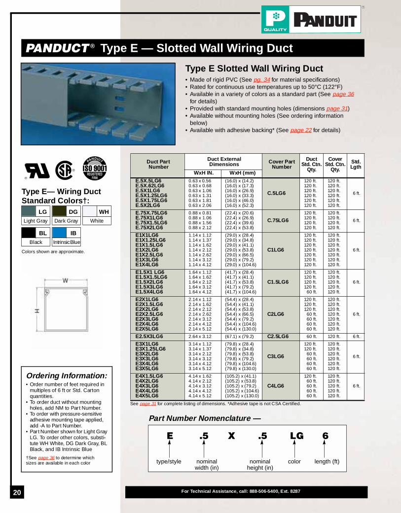
PANDUCT ® Type E — Slotted Wall Wiring Duct
See page 31 for complete listing of dimensions. *Adhesive tape is not CSA Certified.
Duct Part Number
Duct External Dimensions Cover Part
Number
DuctStd. Ctn.
Qty.
Cover Std. Ctn.
Qty.
Std.Lgth
WxH IN. WxH (mm)
E.5X.5LG6E.5X.62LG6E.5X1LG6E.5X1.25LG6E.5X1.75LG6E.5X2LG6
0.63 x 0.560.63 x 0.680.63 x 1.060.63 x 1.310.63 x 1.810.63 x 2.06
(16.0) x (14.2)(16.0) x (17.3)(16.0) x (26.9)(16.0) x (33.3)(16.0) x (46.0)(16.0) x (52.3)
C.5LG6
120 ft.120 ft.120 ft.120 ft.120 ft.120 ft.
120 ft.120 ft.120 ft.120 ft.120 ft.120 ft.
6 ft.
E.75X.75LG6E.75X1LG6E.75X1.5LG6E.75X2LG6
0.88 x 0.810.88 x 1.060.88 x 1.560.88 x 2.12
(22.4) x (20.6)(22.4) x (26.9)(22.4) x (39.6)(22.4) x (53.8)
C.75LG6120 ft.120 ft.120 ft.120 ft.
120 ft.120 ft.120 ft.120 ft.
6 ft.
E1X1LG6E1X1.25LG6E1X1.5LG6E1X2LG6E1X2.5LG6E1X3LG6E1X4LG6
1.14 x 1.121.14 x 1.371.14 x 1.621.14 x 2.121.14 x 2.621.14 x 3.121.14 x 4.12
(29.0) x (28.4)(29.0) x (34.8)(29.0) x (41.1)(29.0) x (53.8)(29.0) x (66.5)(29.0) x (79.2)(29.0) x (104.6)
C1LG6
120 ft.120 ft.120 ft.120 ft.120 ft.120 ft.120 ft.
120 ft.120 ft.120 ft.120 ft.120 ft.120 ft.120 ft.
6 ft.
E1.5X1 LG6E1.5X1.5LG6E1.5X2LG6E1.5X3LG6E1.5X4LG6
1.64 x 1.121.64 x 1.621.64 x 2.121.64 x 3.121.64 x 4.12
(41.7) x (28.4)(41.7) x (41.1)(41.7) x (53.8)(41.7) x (79.2)(41.7) x (104.6)
C1.5LG6
120 ft.120 ft.120 ft.120 ft.
60 ft.
120 ft.120 ft.120 ft.120 ft.120 ft.
6 ft.
E2X1LG6E2X1.5LG6E2X2LG6E2X2.5LG6E2X3LG6E2X4LG6E2X5LG6
2.14 x 1.122.14 x 1.622.14 x 2.122.14 x 2.622.14 x 3.122.14 x 4.122.14 x 5.12
(54.4) x (28.4)(54.4) x (41.1)(54.4) x (53.8)(54.4) x (66.5)(54.4) x (79.2)(54.4) x (104.6)(54.4) x (130.0)
C2LG6
120 ft.120 ft.120 ft.
60 ft.60 ft.60 ft.60 ft.
120 ft.120 ft.120 ft.120 ft.120 ft.120 ft.120 ft.
6 ft.
E2.5X3LG6 2.64 x 3.12 (67.1) x (79.2) C2.5LG6 60 ft. 120 ft. 6 ft.
E3X1LG6E3X1.25LG6E3X2LG6E3X3LG6E3X4LG6E3X5LG6
3.14 x 1.123.14 x 1.373.14 x 2.123.14 x 3.123.14 x 4.123.14 x 5.12
(79.8) x (28.4)(79.8) x (34.8)(79.8) x (53.8)(79.8) x (79.2)(79.8) x (104.6)(79.8) x (130.0)
C3LG6
120 ft.120 ft.
60 ft.60 ft.60 ft.60 ft.
120 ft.120 ft.120 ft.120 ft.120 ft.120 ft.
6 ft.
E4X1.5LG6E4X2LG6E4X3LG6E4X4LG6E4X5LG6
4.14 x 1.624.14 x 2.124.14 x 3.124.14 x 4.124.14 x 5.12
(105.2) x (41.1)(105.2) x (53.8)(105.2) x (79.2)(105.2) x (104.6)(105.2) x (130.0)
C4LG6
120 ft.60 ft.60 ft.60 ft.60 ft.
120 ft.120 ft.120 ft.120 ft.120 ft.
6 ft.
Ordering Information:• Order number of feet required in
multiples of 6 ft or Std. Carton quantities.
• To order duct without mounting holes, add NM to Part Number.
• To order with pressure-sensitive adhesive mounting tape applied, add -A to Part Number.
• Part Number shown for Light Gray LG. To order other colors, substi-tute WH White, DG Dark Gray, BL Black, and IB Intrinsic Blue
†See page 36 to determine which sizes are available in each color
Type E— Wiring DuctStandard Colors†:
Colors shown are approximate.
LG DG WHLight Gray Dark Gray White
BL IBBlack IntrinsicBlue
Part Number Nomenclature —
type/style nominal width (in)
colornominal height (in)
length (ft)
E .5 .5 LG 6X
Type E Slotted Wall Wiring Duct• Made of rigid PVC (See pg. 34 for material specifications)• Rated for continuous use temperatures up to 50°C (122°F)• Available in a variety of colors as a standard part (See page 36
for details)• Provided with standard mounting holes (dimensions page 31)• Available without mounting holes (See ordering information
below)• Available with adhesive backing* (See page 22 for details)

21
PANDUCT ® Type S — Solid Wall Raceway
Type S Solid Wall Raceway• Made of rigid PVC (See pg. 34 for material specifications)• Rated for continuous use temperatures up to 50°C (122°F)• Available in a variety of colors as a standard part (See page 36
for details)• Provided with standard mounting holes (dimensions page 31)• Available without mounting holes (See ordering information
below)• Available with adhesive backing* (See page 22 for details)
See page 31 for complete listing of dimensions. *Adhesive tape is not CSA Certified.
Raceway Part Number
Raceway External Dimensions Cover Part
Number
RacewayStd. Ctn.
Qty.
Cover Std. Ctn.
Qty.
Std.Lgth
WxH IN. WxH (mm)
S.5X.5LG6NMS.5X.62LG6NMS.5X1LG6NMS.5X1.25LG6NMS.5X1.75LG6NMS.5X2LG6NM
0.63 x 0.560.63 x 0.680.63 x 1.060.63 x 1.310.63 x 1.810.63 x 2.06
(16.0) x (14.2)(16.0) x (17.3)(16.0) x (26.9)(16.0) x (33.3)(16.0) x (46.0)(16.0) x (52.3)
C.5LG6
120 ft.120 ft.120 ft.120 ft.120 ft.120 ft.
120 ft.120 ft.120 ft.120 ft.120 ft.120 ft.
6 ft.
S.75X.75LG6NMS.75X1LG6NMS.75X1.5LG6NMS.75X2LG6NM
0.88 x 0.810.88 x 1.060.88 x 1.560.88 x 2.12
(22.4) x (20.6)(22.4) x (26.9)(22.4) x (39.6)(22.4) x (53.8)
C.75LG6120 ft.120 ft.120 ft.120 ft.
120 ft.120 ft.120 ft.120 ft.
6 ft.
S1X1LG6NMS1X1.25LG6NMS1X1.5LG6NMS1X2LG6NMS1X2.5LG6NMS1X3LG6NMS1X4LG6NM
1.14 x 1.121.14 x 1.371.14 x 1.621.14 x 2.121.14 x 2.621.14 x 3.121.14 x 4.12
(29.0) x (28.4)(29.0) x (34.8)(29.0) x (41.1)(29.0) x (53.8)(29.0) x (66.5)(29.0) x (79.2)(29.0) x (104.6)
C1LG6
120 ft.120 ft.120 ft.120 ft.120 ft.120 ft.120 ft.
120 ft.120 ft.120 ft.120 ft.120 ft.120 ft.120 ft.
6 ft.
S1.5X1 LG6NMS1.5X1.5LG6NMS1.5X2LG6NMS1.5X3LG6NMS1.5X4LG6NM
1.64 x 1.121.64 x 1.621.64 x 2.121.64 x 3.121.64 x 4.12
(41.7) x (28.4)(41.7) x (41.1)(41.7) x (53.8)(41.7) x (79.2)(41.7) x (104.6)
C1.5LG6
120 ft.120 ft.120 ft.120 ft.
60 ft.
120 ft.120 ft.120 ft.120 ft.120 ft.
6 ft.
S2X1LG6NMS2X1.5LG6NMS2X2LG6NMS2X2.5LG6NMS2X3LG6NMS2X4LG6NMS2X5LG6NM
2.14 x 1.122.14 x 1.622.14 x 2.122.14 x 2.622.14 x 3.122.14 x 4.122.14 x 5.12
(54.4) x (28.4)(54.4) x (41.1)(54.4) x (53.8)(54.4) x (66.5)(54.4) x (79.2)(54.4) x (104.6)(54.4) x (130.0)
C2LG6
120 ft.120 ft.120 ft.
60 ft.60 ft.60 ft.60 ft.
120 ft.120 ft.120 ft.120 ft.120 ft.120 ft.120 ft.
6 ft.
S2.5X3LG6NM 2.64 x 3.12 (67.1) x (79.2) C2.5LG6 60 ft. 120 ft. 6 ft.
S3X1LG6NMS3X1.25LG6NMS3X2LG6NMS3X3LG6NMS3X4LG6NMS3X5LG6NM
3.14 x 1.123.14 x 1.373.14 x 2.123.14 x 3.123.14 x 4.123.14 x 5.12
(79.8) x (28.4)(79.8) x (34.8)(79.8) x (53.8)(79.8) x (79.2)(79.8) x (104.6)(79.8) x (130.0)
C3LG6
120 ft.120 ft.
60 ft.60 ft.60 ft.60 ft.
120 ft.120 ft.120 ft.120 ft.120 ft.120 ft.
6 ft.
S4X1.5LG6NMS4X2LG6NMS4X3LG6NMS4X4LG6NMS4X5LG6NM
4.14 x 1.624.14 x 2.124.14 x 3.124.14 x 4.124.14 x 5.12
(105.2) x (41.1)(105.2) x (53.8)(105.2) x (79.2)(105.2) x (104.6)(105.2) x (130.0)
C4LG6
120 ft.60 ft.60 ft.60 ft.60 ft.
120 ft.120 ft.120 ft.120 ft.120 ft.
6 ft.
Type S— RacewayStandard Colors†:
Colors shown are approximate.
LG DG WH
Light Gray Dark Gray White
BL IB
Black IntrinsicBlue
Part Number Nomenclature —
type/style color length (ft)
S .5 .5 LG 6X
nominal width (in)
nominal height (in)
NM
no mount-ing holes
Ordering Information:• Order number of feet required in
multiples of 6 ft or Std. Carton quantities.
• To order duct with mounting holes, delete NM from Part Number.
• To order with pressure-sensitive adhesive mounting tape applied, add -A to Part Number.
• Part Number shown for Light Gray LG. To order other colors, substi-tute WH for White, DG for Dark Gray, BL for Black, and IB for Intrinsic Blue
†See page 36 to determine which sizes are available in each color

22 For Technical Assistance, call: 888-506-5400, Ext. 8287
PANDUCT ® Adhesive Backed Wiring Duct
Adhesive Backed Wiring DuctFor All Wiring Duct Types and SizesAdhesive backing is an available option for all types andsizes of PANDUIT Wiring Duct and Raceway. The adhe-sive backing is factory applied and ready for use. Simplypeel off the tape's protective liner and mount the duct toa clean, dry, grease-free surface.
As a PERMANENT MOUNTING METHOD Eliminates the drilling and tapping of holes, labor and time required to install separate mounting devices.
As a TEMPORARY MOUNTING METHODHolds duct in place to free installer's hands to further secure duct with screws, rivets, etc.
DUCT SIZE WxH
ROWS OFTAPE
TAPE
WIDTH THICKNESS
In. (mm) In. (mm)
.5X.5 thru 1.5X4 1 .50 (12.7) .0313 (.8)
2X1 thru 3X3 2 .50 (12.7) .0313 (.8)
3X4 thru 3X5 2 .75 (19.1) .0313 (.8)
4X1.5 thru 4X3 2 .50 (12.7) .0313 (.8)
4X4 thru 6X4 2 .75 (19.1) .0313 (.8)
Material Specifications Table for Factory Applied Tape :
DUCT SIZE WxH
TAPE PART NUMBER
ROLLLENGTH
STDPKGQTY
STD CTNQTY
Yds. (m)
.5X.5 thru 1.5X4P32W2A2-50-7 7.0 (6.4) 1 Roll 100 Rolls
P32W2A2-50-72 72.0 (65.5) 1 Roll 9 Rolls
2X1 thru 3X3P32W2A2-50-7 7.0 (6.4) 1 Roll 100 Rolls
P32W2A2-50-72 72.0 (65.5) 1 Roll 9 Rolls
3X4 thru 3X5P32W2A2-75-7 7.0 (6.4) 1 Roll 60 Rolls
P32W2A2-75-72 72.0 (65.5) 1 Roll 7 Rolls
4X1.5 thru 4X3P32W2A2-50-7 7.0 (6.4) 1 Roll 100 Rolls
P32W2A2-50-72 72.0 (65.5) 1 Roll 9 Rolls
4X4 thru 6X4P32W2A2-75-7 7.0 (6.4) 1 Roll 60 Rolls
P32W2A2-75-72 72.0 (65.5) 1 Roll 7 Rolls
To Order Tape Separately:
Ordering Information:For Factory Applied Tape:• Add -A to the Duct or Raceway
Part Number
To Order Tape Separately:• Order number of rolls required
Factory Applied Tape —To order any Panduit Wiring Duct or Raceway with pressure-sensitive adhesive mounting tape factory applied add -A to the Duct/Raceway part
type/style color length (ft)
G 2 1 LG 6X
nominal width (in)
nominal height (in)
-A
factory applied adhesive tape
• Recommended installation tempera-ture is 70°F (21°C)
• UL Recognized service temperature is 32°F (0°C) to 140°F (60°C)
• Optimum recommended dwell time for acrylic adhesive is 8 hours
• Recommended tape load is 1/2 lb. per square inch of tape area
Features & Benefits

23
ORDERING INFORMATION: Order in multiples of standard pkg. qty.
PANDUCT ® Notching Tool (For use with all duct/raceway types)A heavy duty tool used to notch slotted wall wiring duct from the bottom of a slot to the base of the duct. Used with all sizes of slotted wall wiring duct.
DNT-100 Hand held notching tool 1
ORDERING INFORMATION: Order in multiples of standard pkg. qty.
PANDUCT ® Nylon Rivet Installation ToolAn easy to use hand held tool to install PANDUIT Nylon rivets.
TNR Hand held nylon rivet installation tool 1
PANDUCT ® Nylon RivetsNR1-C
Nylon rivet for use with TNR Rivet Tool shown above100 pcs.
NR1-M 1000 pcs.
Step 1 — Insert rivet into tool
PANDUCT ® Installation Tools
Step 2 — Position rivet into hole
Step 3 — Install rivet with sharp tap
NOTE: Always use approved safety goggles when using any toolsORDERING INFORMATION: Order in multiples of standard pkg. qty.
Part Number DescriptionStd
Pkg Qty.
PANDUCT ® Cutting Tool (For use with all duct/raceway types)Heavy duty steel tool incorporates a new, improved blade design which minimizes cutting force and blade wear. Provides a smooth burr-free cut on both wiring duct and cover.
DCT Hand held duct and cover cutting tool 1
Replacement Blade Kit (Includes Blade & Nylon Insert)DCT-BLD Replacement blade and nylon insert for above tool 1
Replacement Nylon InsertDCT-RI Replacement nylon insert for above tool 1
• Quickly & easily cuts duct & cover
• Notches duct sidewalls to bottom scoreline for “T” and corner junctions
Step 1 — Notch wiring duct sidewall at the desired opening width
Use to cut any PANDUCT ® Duct or Cover
Total Thickness of Panel & Duct
Panel Hole Dia. Needed
.158" (4.0)–.187" (4.7)
.188" (4.8)–.218" (5.5)
.219" (5.6)–.250" (6.4).251" (6.5) and up
.187" (4.7)
.193" (4.9)
.203" (5.2)
.213" (5.4)
Step 2 — Snap off notched wiring duct piece at bottom scoreline
DCT-BLD
DCT-RI
TNR NR1
Note: Cut cover as shown, latch side-up.

24 For Technical Assistance, call: 888-506-5400, Ext. 8287
PANDUCT ® Accessories—Divider Wall
Installing Base— Install a DB-C at least every 12" - 16" as duct is installed.
Duct Divider WallFor All PVC Duct Types and Sizes (G, F, FS, D)The wiring duct divider wall is mounted inside any PVC wir-ing duct in order to create multiple channels within the wir-ing duct. Simply use the mounting bases below wheninstalling the duct and the divider wall will “snap” on.
ORDERING INFORMATION: Order in multiples of standard foot length
Part NumberFor Duct Height
Inches (mm)Std.
LengthStd
Ctn. Qty.
PANDUCT ® Divider Wall—For Type G, F, FS, D DuctsPVC Divider Wall snaps onto mounting base below
D1H6 1.00 (25.4) 6 ft. 120 ft.
D1.5H6 1.50 (38.1) 6 ft. 120 ft.
D2H6 2.00 (50.8) 6 ft. 120 ft.
D3H6 3.00 (76.2) 6 ft. 120 ft.
D4H6 4.00 (101.6) 6 ft. 120 ft.
PANDUCT ® Slotted Divider Wall—For Type G, F, FS, D DuctsPVC Divider Wall snaps onto mounting base below
SD2H6 2.00 (50.8) 6 ft. 120 ft.
SD3H6 3.00 (76.2) 6 ft. 120 ft.
SD4H6 4.00 (101.6) 6 ft. 120 ft.
• Installed when mounting duct• Acts as a shroud around the screw to
protect wires from abrasionORDERING INFORMATION: Order number of pieces required in multiples of standard pkg. qty.
Part Number Used with AnchorsStd
Pkg. Qty.
PANDUCT ® Divider Wall Mounting BaseMounting Base accepts divider wall above. Recommend use of 4 mounting bases for every 6 feet of divider wall installed.
DB-C Panduit NR1 (See pg. 23) or #8 or #10 screw. 100 pcs.
• Both versions snap onto DB-Cmounting base
12-16"
Installing Divider Wall— Snap the divider wall to the mounting bases already installed.

25
PANDUCT ® Accessories—Wire Retainers
ORDERING INFORMATION: Order number of pieces required in multiples of standard pkg. qty.
Part Number MaterialLength
Inches (mm)Std
Pkg. Qty.
PANDUCT ® Divider Wall Wire Retainer (snaps-on to divider wall) Wire retainer for use with duct divider wall (shown on previous page).
T3WR-C NYLON 1.05" (26.7) 100 pcs.
Divider Wall Wire Retainer• “Snaps-on” directly to the divider wall• Made of Nylon
ORDERING INFORMATION: Order number of pieces required in multiples of standard pkg. qty.
Part Number Material
For Duct SizeStd
Pkg. Qty.Width Height
PANDUCT ® Type G Duct and Type E Duct Wire RetainerWire retainer for use with Type G Duct.
WR2-C NYLON 2.0" (50.8) 4.0" (101.6) or Under 100 pcs.
WR3-C NYLON 3.0" (76.2) 4.0" (101.6) or Under 100 pcs.
WR4-C NYLON 4.0" (101.6) 4.0" (101.6) or Under 100 pcs.
WR5-C NYLON Use with: 2x5, 3x5, 4x5 or 6x4 G-Duct 100 pcs.Wire Retainer—Type G, E• Snaps into slots of Type G & Type E Duct • Made of Nylon
NOTE: Full length is used with 4" wide duct. For smaller widths, break off segments at scorelines.ORDERING INFORMATION: Order number of pieces required in multiples of standard pkg. qty.
Part Number MaterialFor Duct Width
Inches (mm)Std
Pkg. Qty.
PANDUCT ® Type F Duct Wire Retainer/Labeling Device Wire retainer for use with Type F Duct. Can also be used as a labeling device (for labels see page 28)
FWR-C RIGID PVC
1.50" (38.1)2.00" (50.8)3.00" (76.2)
4.00" (101.6)
100 pcs.
Wire Retainer—Type F • Snaps into slots of Type F Duct• One size fits four different duct widths• Made of Rigid PVC
NOTE: Full length is used with 2" wide duct. For smaller widths, break off segments at scorelines.ORDERING INFORMATION: Order number of pieces required in multiples of standard pkg. qty.
Part Number MaterialFor Duct Width
Inches (mm)Std
Pkg. Qty.
PANDUCT ® Type FS & D Duct Wire Retainer Wire retainer for use with Type FS Solid Wall Raceway or Type D Round Hole Duct. Supplied with adhesive backing for fast installation.
WRS-A-C10 RIGID PVC1.00" (25.4)1.50" (38.1)2.00" (50.8)
100 pcs.
Wire Retainer—Type FS, D • Mounts onto walls of Type FS Raceway
or Type D Duct• One size fits three different duct widths

26 For Technical Assistance, call: 888-506-5400, Ext. 8287
PANDUCT ® Accessories—Duct Corner & Joining Strips
ORDERING INFORMATION: Order number of feet required in multiples of 6ft. or Std. Carton quantities.
Part Number MaterialFor Duct Height Color
Std. Length
StdCtn. Qty.
PANDUCT ® Duct Corner Strip— 6 Foot LengthsFor All PVC Wiring Duct Types 6 foot length. Joins sections of duct together at corners or “T” junctions. Used with any PVC Wiring Duct, Type G, F and D Duct and FS Raceway. 6 foot length is cut by user to fit duct height.
CS1BL6CS1DG6CS1LG6CS1WH6
RIGID PVC Cut to Size
BlackDark GrayLight Gray
White
6 ft. 120 ft.Duct Corner Strip• Snaps onto duct at corner or “T”
junctions for smooth, round corners• Strip is cut to length (6 foot lengths) or
is available in pre-cut pieces
NOTE: Actual length of CSP pre-cut pieces are less than “For Duct Height” shown.ORDERING INFORMATION: Order number of pieces required in multiples of standard pkg. qty.
Part Number MaterialFor Duct Height Color
Std. Pkg. Qty
PANDUCT ® Duct Corner Strip— Pre Cut PiecesFor All PVC Wiring Duct Types Pre-cut pieces are cut to size. Joins sections of duct together at corners or “T” junctions. Used with any PVC Wiring Duct, Type G, F and D Duct and FS Raceway.
CSP1LG-QCSP1.5LG-QCSP2LG-QCSP3LG-QCSP4LG-Q
RIGID PVC
1.00" (25.4)1.50" (38.1)2.00" (50.8)3.00" (76.2)
4.00" (101.6)
Light Grayonly 25 pcs.
ORDERING INFORMATION: Order number of feet required in multiples of 6ft. or Std. Carton quantities.
Part Number MaterialFor Duct Height Color
Std. Length
StdCtn. Qty.
PANDUCT ® Duct Joining Strip— 6 Foot LengthsFor All PVC Wiring Duct Types 6 foot length. Joins sections of duct together. Used with any PVC Wiring Duct, Type G, F and D Duct and FS Raceway. 6 foot length is cut by user to fit duct height.
DJS1BL6DJS1DG6DJS1LG6DJS1WH6
RIGID PVC Cut to Size
BlackDark GrayLight Gray
White
6 ft. 120 ft.
NOTE: Actual length of DJSP pre-cut pieces are less than “For Duct Height” shown.ORDERING INFORMATION: Order number of pieces required in multiples of standard pkg. qty.
Part Number MaterialFor Duct Height Color
Std. Pkg. Qty
PANDUCT ® Duct Joining Strip— Pre Cut PiecesFor All PVC Wiring Duct Types Pre-cut pieces are cut to size. Joins sections of duct together. Used with any PVC Wiring Duct, Type G, F and D Duct and FS Raceway.
DJSP1LG-QDJSP1.5LG-QDJSP2LG-QDJSP3LG-QDJSP4LG-Q
RIGID PVC
1.00" (25.4)1.50" (38.1)2.00" (50.8)3.00" (76.2)4.00" (101.6)
Light Grayonly 25 pcs.
Duct Joining Strip• Snaps onto duct to join sections
together• Strip is cut to length (6 foot lengths) or
is available in pre-cut pieces
27
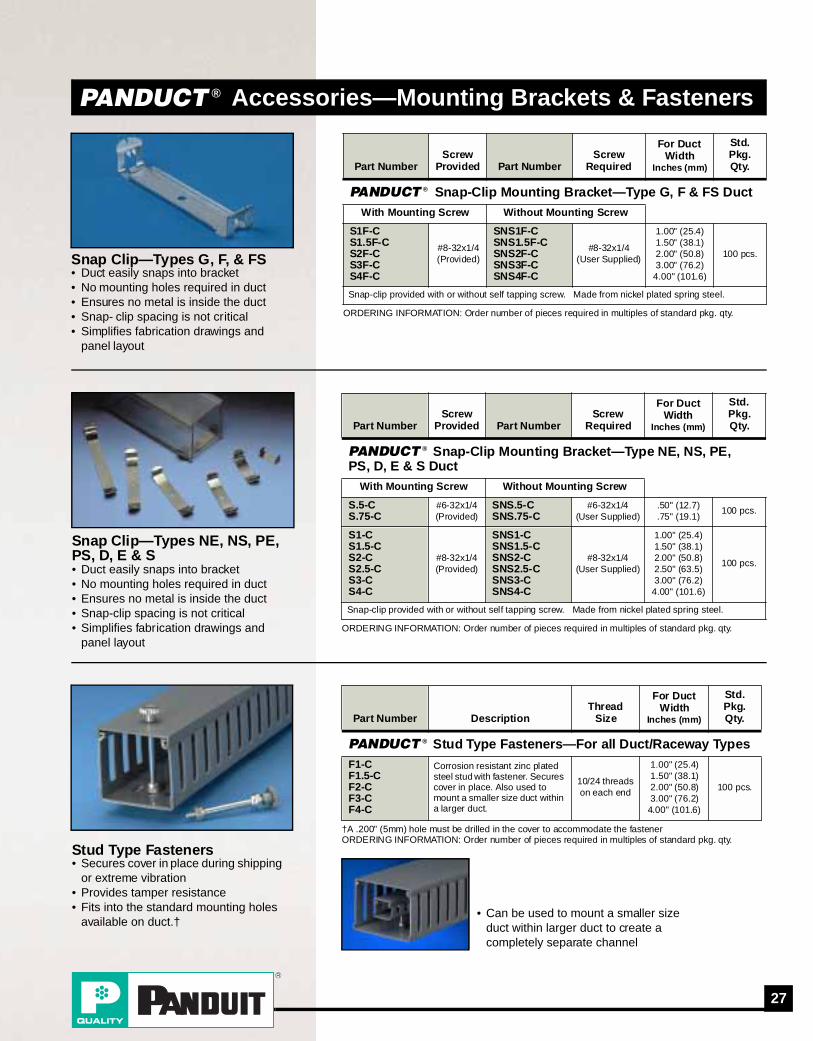
PANDUCT ® Accessories—Mounting Brackets & Fasteners
ORDERING INFORMATION: Order number of pieces required in multiples of standard pkg. qty.
Part NumberScrew
Provided Part NumberScrew
Required
For Duct Width
Inches (mm)
Std. Pkg. Qty.
PANDUCT ® Snap-Clip Mounting Bracket—Type G, F & FS DuctWith Mounting Screw Without Mounting Screw
S1F-CS1.5F-CS2F-CS3F-CS4F-C
#8-32x1/4(Provided)
SNS1F-CSNS1.5F-CSNS2F-CSNS3F-CSNS4F-C
#8-32x1/4(User Supplied)
1.00" (25.4)1.50" (38.1)2.00" (50.8)3.00" (76.2)
4.00" (101.6)
100 pcs.
Snap-clip provided with or without self tapping screw. Made from nickel plated spring steel.
Snap Clip—Types G, F, & FS• Duct easily snaps into bracket• No mounting holes required in duct• Ensures no metal is inside the duct• Snap- clip spacing is not critical• Simplifies fabrication drawings and
panel layout
ORDERING INFORMATION: Order number of pieces required in multiples of standard pkg. qty.
Part NumberScrew
Provided Part NumberScrew
Required
For Duct Width
Inches (mm)
Std. Pkg. Qty.
PANDUCT ® Snap-Clip Mounting Bracket—Type NE, NS, PE, PS, D, E & S Duct
With Mounting Screw Without Mounting Screw
S.5-CS.75-C
#6-32x1/4(Provided)
SNS.5-CSNS.75-C
#6-32x1/4(User Supplied)
.50" (12.7)
.75" (19.1)100 pcs.
S1-CS1.5-CS2-CS2.5-CS3-CS4-C
#8-32x1/4(Provided)
SNS1-CSNS1.5-CSNS2-CSNS2.5-CSNS3-CSNS4-C
#8-32x1/4(User Supplied)
1.00" (25.4)1.50" (38.1)2.00" (50.8)2.50" (63.5)3.00" (76.2)
4.00" (101.6)
100 pcs.
Snap-clip provided with or without self tapping screw. Made from nickel plated spring steel.
Snap Clip—Types NE, NS, PE, PS, D, E & S • Duct easily snaps into bracket• No mounting holes required in duct• Ensures no metal is inside the duct• Snap-clip spacing is not critical• Simplifies fabrication drawings and
panel layout
†A .200" (5mm) hole must be drilled in the cover to accommodate the fastenerORDERING INFORMATION: Order number of pieces required in multiples of standard pkg. qty.
Part Number DescriptionThread
Size
For Duct Width
Inches (mm)
Std. Pkg. Qty.
PANDUCT ® Stud Type Fasteners—For all Duct/Raceway TypesF1-CF1.5-CF2-CF3-CF4-C
Corrosion resistant zinc plated steel stud with fastener. Secures cover in place. Also used to mount a smaller size duct within a larger duct.
10/24 threads on each end
1.00" (25.4)1.50" (38.1)2.00" (50.8)3.00" (76.2)
4.00" (101.6)
100 pcs.
Stud Type Fasteners • Secures cover in place during shipping
or extreme vibration• Provides tamper resistance• Fits into the standard mounting holes
available on duct.†• Can be used to mount a smaller size
duct within larger duct to create a completely separate channel

28 For Technical Assistance, call: 888-506-5400, Ext. 8287
PANDUCT ® Accessories—Labeling
ORDERING INFORMATION: Order number of pieces required in multiples of standard pkg. qty.
Part Number MaterialLength
Inches (mm)Std
Pkg. Qty.
PANDUCT ® Type F Duct Wire Retainer/Labeling Device Wire retainer for use with Type F Duct. Also used as a labeling device.
FWR-C RIGID PVC
1.50" (38.1)2.00" (50.8)3.00" (76.2)
4.00" (101.6)
100 pcs.
Wire Retainer/Labeling Device—Type F• Used to identify both wires exiting duct
and adjacent terminations• Use with write-on, computer printable
labels, or write directly on the labeling device
• Made of rigid PVC• For use with F Duct Only
Labeling Outside Duct— Break off the last segment from wire retainer (below 1.5 mark) and snap onto the back of the remaining segment. Install label & mount between fingers facing outward.
Labeling Inside Duct— Install label (shown below) on Wire Retainer. Install label & mount between fingers facing inward.
ORDERING INFORMATION: Order number of pieces required in multiples of standard pkg. qty.
Part Number Color Description
StdPkg. Qty.
StdCtn. Qty.
Marking Pens—For use with FWR-C Labeling Device PX-0 Black
Regular tip pen12 pcs. 48 pcs.
PX-2 Red 12 pcs. 48 pcs.
PFX-0 BlackFine tip pen
12 pcs. 48 pcs.
PFX-2 Red 12 pcs. 48 pcs.
ORDERING INFORMATION: Order number of pieces required in multiples of standard pkg. qty.■TEDLAR is a registered trademark of E.I. Dupont Co.NOTE: For more information on computer printable labels and software contact factory to request catalog SA101N315A-ID
Part Number Description
Label SizeWxH
Labels Per Row
Rows Per
FanfoldSheet Width
StdPkg. Qty.
Identification Labels—For use with FWR-C Labeling Device
PDL-110-1■ TEDLAR
Adhesive backed2.00" x
.38" 3 24 7.20"1000 labels
PDL-111-1 MYLAR Adhesive backed
2.00" x .38" 3 24 7.20"
1000 labels
PDL-PB1Non-smudge
paper with overlaminate
2.00" x .38"
3 24 7.20" 1000 labelsLabels for FWR-C Labeling
Device• Write-on labels attach to the recessed
area on FWR-C labeling device • Computer printable or hand writable• Individually die cut
PX-0PX-2
PFX-0PFX-2
• Fast drying permanent ink

29
Type G Plastic Wiring Duct DimensionsDimensions are shown for reference only. Consult factory for specific dimensional needs.
EDH
F
A
T
B
C
PANDUCT ® Type G Wiring Duct—Dimensions
Mounting Hole Dimensions:For .5", .75", 1.0" and 1.5" width duct:
4"(102)
2"(51)
C.195"
(5) Typ
.50"(12)Typ
For 2.0", 2.5", 3.0", 4.0" and 6.0" width duct:
4"(102)
2"(51)
KK
C
Note: “A” dimension is measured at baseNote: “K” dimension shown in mounting hole dimensions below
NOTE: For Type G Duct, if no mounting holes are required, add NM to the Part Number
(see pg. 36 for color and size chart)
DUCT SIZE(W x H)
DIMENSIONS-Inches (mm)
A B C D E F H K T
.5 x .5 0.69 0.56 0.69 0.38 0.20 0.50 0.50 0.05(12.7) (12.7) (17.5) (14.2) (17.5) (9.5) (5.0) (12.7) (12.7) (1.3)
.5 x 1 0.69 1.09 0.69 0.75 0.20 0.50 1.00 0.05(12.7) (25.4) (17.5) (27.1) (17.5) (19.1) (5.0) (12.7) (25.4) (1.3)
.75 x .75 0.94 0.83 0.94 0.58 0.31 0.80 0.75 0.06(19.1) (19.1) (23.9) (21.0) (23.9) (14.8) (7.9) (20.3) (19.1) (1.4)
.75 x 1 0.94 1.09 0.94 0.75 0.31 0.80 1.00 0.06(19.1) (25.4) (23.9) (27.6) (23.9) (19.1) (7.9) (20.3) (25.4) (1.4)
.75 x 1.5 0.94 1.58 0.94 1.20 0.31 0.80 1.50 0.07(19.1) (38.1) (23.9) (40.0) (23.9) (30.5) (7.9) (20.3) (38.1) (1.8)
.75 x 2 0.94 2.09 0.94 1.63 0.31 0.80 2.00 0.08(19.1) (50.8) (23.9) (53.0) (23.9) (41.3) (7.9) (20.3) (50.8) (2.0)
1 x 1 1.25 1.09 1.25 0.75 0.31 0.80 1.00 0.06(19.1) (25.4) (31.8) (27.6) (31.8) (19.1) (7.9) (20.3) (25.4) (1.4)
1 x 1.5 1.25 1.59 1.25 1.20 0.31 0.80 1.50 0.07(25.4) (38.1) (31.8) (40.3) (31.8) (30.5) (7.9) (20.3) (38.1) (1.8)
1 x 2 1.25 2.09 1.25 1.63 0.31 0.80 2.00 0.08(25.4) (38.1) (31.8) (53.0) (31.8) (41.3) (7.9) (20.3) (50.8) (2.0)
1 x 3 1.25 3.10 1.25 2.63 0.31 1.00 3.00 0.10(25.4) (76.2) (31.8) (78.6) (31.8) (66.7) (7.9) (25.4) (76.2) (2.4)
1 x 4 1.25 4.10 1.25 3.63 0.31 1.00 4.00 0.11(25.4) (101.5) (31.8) (104.0) (31.8) (92.1) (7.9) (25.4) (101.6) (2.7)
1.5 x 1 1.75 1.09 1.75 7.50 0.31 0.80 1.00 0.06(38.1) (25.4) (44.5) (27.6) (44.5) (190.5) (7.9) (20.3) (25.4) (1.5)
1.5 x 1.5 1.75 1.59 1.75 1.20 0.31 0.80 1.50 0.07(38.1) (38.1) (44.5) (40.3) (44.5) (30.5) (7.9) (20.3) (38.1) (1.8)
1.5 x 2 1.75 2.09 1.75 1.63 0.31 0.80 2.00 0.08(38.1) (50.8) (44.5) (53.0) (44.5) (41.3) (7.9) (20.3) (50.8) (2.0)
1.5 x 3 1.75 3.10 1.75 2.63 0.31 1.00 3.00 0.10(38.1) (76.2) (44.5) (78.6) (44.5) (66.7) (7.9) (25.4) (76.2) (2.4)
1.5 x4 1.75 4.10 1.75 3.63 0.31 1.00 4.00 0.11(38.1) (101.6) (44.5) (104.0) (44.5) (92.1) (7.9) (25.4) (101.6) (2.7)
2 x1 2.25 1.09 2.25 0.75 0.31 0.80 1.00 0.50 0.06(50.8) (25.4) (57.2) (27.6) (57.2) (19.1) (7.9) (20.3) (25.4) (12.7) (1.5)
2x1.5 2.25 1.59 2.25 1.20 0.31 0.80 1.50 0.50 0.70(50.8) (38.1) (57.2) (40.3) (57.2) (30.5) (7.9) (20.3) (38.1) (12.7) (17.8)
2x2 2.25 2.09 2.25 1.63 0.31 0.80 2.00 0.50 0.08(50.8) (50.8) (57.2) (53.0) (57.2) (41.3) (7.9) (20.3) (50.8) (12.7) (2.0)
2x3 2.25 3.10 2.25 2.63 0.31 1.00 3.00 0.50 0.10(50.8) (76.2) (57.2) (78.6) (57.2) (66.7) (7.9) (25.4) (76.2) (12.7) (2.4)
2x4 2.25 4.10 2.25 3.63 0.31 1.00 4.00 0.50 0.11(50.8) (101.6) (57.2) (104.0) (57.2) (92.1) (7.9) (25.4) (101.6) (12.7) (2.7)
2x5 2.25 5.11 2.25 4.63 0.38 1.33 5.00 0.50 0.12(50.8) (127.0) (57.2) (129.7) (57.2) (117.5) (9.5) (33.9) (127.0) (12.7) (2.9)
2.5 x 3 2.75 3.10 2.75 2.63 0.31 1.00 3.00 0.75 0.10(63.5) (76.2) (69.9) (78.7) (69.9) (66.7) (7.9) (25.4) (76.2) (19.1) (2.5)
3x1 3.25 1.09 3.25 0.75 0.31 0.80 1.00 0.50 0.08(76.2) (25.4) (82.6) (27.6) (82.6) (19.1) (7.9) (20.3) (25.4) (12.7) (1.9)
3x2 3.25 2.09 3.25 1.63 0.31 0.80 2.00 1.00 0.08(76.2) (50.8) (82.6) (53.1) (82.6) (41.3) (7.9) (20.3) (50.8) (25.4) (2.0)
3x3 3.25 3.10 3.25 2.63 0.31 1.00 3.00 1.00 0.10(76.2) (76.2) (82.6) (78.7) (82.6) (66.7) (7.9) (25.4) (76.2) (25.4) (2.4)
3x4 3.25 4.10 3.25 3.63 0.31 1.00 4.00 1.00 0.11(76.2) (101.6) (82.6) (104.1) (82.6) (92.1) (7.9) (25.4) (101.6) (25.4) (2.7)
3x5 3.25 5.11 3.25 4.63 0.38 1.33 5.00 1.00 0.12(76.2) (127.0) (82.6) (129.8) (82.6) (117.5) (9.5) (33.9) (127.0) (25.4) (2.9)
4 x 1.5 4.25 1.59 4.25 1.20 0.31 0.80 1.50 1.50 0.07(101.6) (38.1) (108.0) (40.3) (108.0) (30.5) (7.9) (20.3) (38.1) (38.1) (1.8)
4x2 4.25 2.08 4.25 1.63 0.31 0.80 2.00 1.50 0.08(101.6) (50.8) (108.0) (52.8) (108.0) (41.3) (7.9) (20.3) (50.8) (38.1) (2.0)
4x3 4.25 3.10 4.25 2.63 0.31 1.00 3.00 1.50 0.10(101.6) (76.2) (108.0) (78.7) (108.0) (66.7) (7.9) (25.4) (76.2) (38.1) (2.5)
4x4 4.25 4.10 4.25 3.63 0.31 1.00 4.00 1.50 0.11(101.6) (101.6) (108.0) (104.1) (108.0) (92.1) (7.9) (25.4) (101.6) (38.1) (2.7)
4x5 4.25 5.11 4.25 4.63 0.38 1.33 5.00 1.50 0.12(101.6) (127.0) (108.0) (129.8) (108.0) (117.5) (9.5) (33.9) (127.0) (38.1) (2.9)
6x4 6.25 4.11 6.25 3.63 0.31 1.00 4.00 2.50 0.11(152.4) (101.6) (158.8) (104.4) (158.8) (92.1) (7.9) (25.4) (101.6) (63.5) (2.8)
ON
CE
NT
ER
LIN
E

30 For Technical Assistance, call: 888-506-5400, Ext. 8287
>Available for Type FS Duct only (see pg. 36 for color and size chart).
DUCT SIZE(W x H)
DIMENSIONS-Inches (mm) A B C D E F H K T
.5 x .5 0.69 0.56 0.69 0.38 0.20 0.50 0.50 0.05(12.7) (12.7) (17.5) (14.2) (17.5) (9.5) (5.0) (12.7) (12.7) (1.3)
.5 x 1 0.69 1.09 0.69 0.75 0.20 0.50 1.00 0.05(12.7) (25.4) (17.5) (27.6) (17.5) (19.1) (5.0) (12.7) (25.4) (1.3)
.75 x .75 0.94 0.83 0.94 0.58 0.20 0.50 0.75 0.06(19.1) (19.1) (23.9) (21.0) (23.9) (14.8) (5.0) (12.7) (19.1) (1.4)
.75 x 1 0.94 1.09 0.94 N/A N/A N/A 1.00 0.07(19.1) (25.4) (23.9) (27.6) (23.9) (25.4) (1.4)
.75 x 1.5 0.94 1.58 0.94 1.20 0.20 0.50 1.50 0.07(19.1) (38.1) (23.9) (40.0) (23.9) (30.5) (5.0) (12.7) (38.1) (1.8)
.75 x 2 0.94 2.09 0.94N/A N/A N/A
2.00 0.08(19.1) (50.8) (23.9) (53.0) (23.9) (50.8) (2.0)
1 x 1 1.25 1.09 1.25 0.75 0.20 0.50 1.00 0.06(19.1) (25.4) (31.8) (27.6) (31.8) (19.1) (5.0) (12.7) (25.4) (1.4)
1 x 1.5 1.25 1.59 1.25 1.20 0.20 0.50 1.50 0.07(25.4) (38.1) (31.8) (40.3) (31.8) (30.5) (5.0) (12.7) (38.1) (1.8)
1 x 2 1.25 2.09 1.25 1.63 0.20 0.50 2.00 0.08(25.4) (38.1) (31.8) (53.0) (31.8) (41.3) (5.0) (12.7) (50.8) (2.0)
1 x 3 1.25 3.10 1.25 2.63 0.20 0.50 3.00 0.10(25.4) (76.2) (31.8) (78.6) (31.8) (66.7) (5.0) (12.7) (76.2) (2.4)
1.5 x 1 1.75 1.09 1.75 0.75 0.20 0.50 1.00 0.06(38.1) (25.4) (44.5) (27.6) (44.5) (19.1) (5.0) (12.7) (25.4) (1.5)
1.5 x 1.5 1.75 1.59 1.75 1.20 0.20 0.50 1.50 0.07(38.1) (38.1) (44.5) (40.3) (44.5) (30.5) (5.0) (12.7) (38.1) (1.8)
1.5 x 2 1.75 2.09 1.75 1.63 0.20 0.50 2.00 0.08(38.1) (50.8) (44.5) (53.0) (44.5) (41.3) (5.0) (12.7) (50.8) (2.0)
1.5 x 3 1.75 3.10 1.75 2.63 0.20 0.50 3.00 0.10(38.1) (76.2) (44.5) (78.6) (44.5) (66.7) (5.0) (12.7) (76.2) (2.4)
2 x1 2.25 1.09 2.25 0.75 0.20 0.50 1.00 0.50 0.06(50.8) (25.4) (57.2) (27.6) (57.2) (19.1) (5.0) (12.7) (25.4) (12.7) (1.5)
2x1.5 2.25 1.59 2.25 1.20 0.20 0.50 1.50 0.50 0.07(50.8) (38.1) (57.2) (40.3) (57.2) (30.5) (5.0) (12.7) (38.1) (12.7) (1.8)
2x2 2.25 2.09 2.25 1.63 0.20 0.50 2.00 0.50 0.08(50.8) (50.8) (57.2) (53.0) (57.2) (41.3) (5.0) (12.7) (50.8) (12.7) (2.0)
2x3 2.25 3.10 2.25 2.63 0.20 0.50 3.00 0.50 0.10(50.8) (76.2) (57.2) (78.6) (57.2) (66.7) (5.0) (12.7) (76.2) (12.7) (2.4)
2x4 2.25 4.10 2.25 3.63 0.20 0.50 4.00 0.50 0.11(50.8) (101.6) (57.2) (104.0) (57.2) (92.1) (5.0) (12.7) (101.6) (12.7) (2.7)
2x5 2.25 5.11 2.25 4.63 0.20 0.50 5.00 0.50 0.12(50.8) (127.0) (57.2) (129.7) (57.2) (117.5) (5.0) (12.7) (127.0) (12.7) (2.9)
2.5 x 3 2.75 3.10 2.75 N/A N/A N/A 3.00 N/A 0.10(63.5) (76.2) (69.9) (78.7) (69.9) (76.2) (2.4)
3x1 3.25 1.09 3.25 0.75 0.20 0.50 1.00 1.00 0.08(76.2) (25.4) (82.6) (27.7) (82.6) (19.1) (5.0) (12.7) (25.4) (25.4) (2.0)
3x2 3.25 2.09 3.25 1.63 0.20 0.50 2.00 1.00 0.08(76.2) (50.8) (82.6) (53.1) (82.6) (41.3) (5.0) (12.7) (50.8) (25.4) (2.0)
3x3 3.25 3.10 3.25 2.63 0.20 0.50 3.00 1.00 0.10(76.2) (76.2) (82.6) (78.7) (82.6) (66.7) (5.0) (12.7) (76.2) (25.4) (2.4)
4 x 1.5 4.25 1.59 4.25N/A N/A N/A
1.50N/A
0.08(101.6) (38.1) (108.0) (40.3) (108.0) (38.1) (2.0)
4x2 4.25 2.08 4.25 1.63 0.20 0.50 2.00 1.50 0.08(101.6) (50.8) (108.0) (52.8) (108.0) (41.3) (5.0) (12.7) (50.8) (38.1) (2.0)
4x3 4.25 3.10 4.25 2.63 0.20 0.50 3.00 1.50 0.10(101.6) (76.2) (108.0) (78.7) (108.0) (66.7) (5.0) (12.7) (76.2) (38.1) (2.5)
4x4 4.25 4.10 4.25 3.63 0.20 0.50 4.00 1.50 0.11(101.6) (101.6) (108.0) (104.1) (108.0) (92.1) (5.0) (12.7) (101.6) (38.1) (2.7)
4x5 4.25 5.11 4.25 4.63 0.20 0.50 5.00 1.50 0.12(101.6) (127.0) (108.0) (129.8) (108.0) (117.5) (5.0) (12.7) (127.0) (38.1) (2.9)
6x4 6.25 4.11 6.25 N/A N/A N/A 4.00 N/A 0.11(152.4) (101.6) (158.8) (104.4) (158.8) (101.6) (2.8)
Type F & FS Plastic Wiring Duct DimensionsDimensions are shown for reference only. Consult factory for specific dimensional needs.
A
TB
C
E DH
F
PANDUCT ® Type F & FS Wiring Duct—Dimensions
Mounting Hole Dimensions:For .5", .75", 1.0" and 1.5" width duct:
2"(51)
2"(51)
.195"(5)
TWP
C
.50"(12)TWP
For 2.0", 2.5", 3.0", 4.0" and 6.0" width duct:
2"(51)
KK
C
2"(51)
Note: “A” dimension is measured at baseNote: “K” dimension shown in mounting hole dimensions below
NOTE: For Type F Duct, if no mounting holes are required, add NM to the Part NumberNOTE 2: For Type FS Duct, no mounting holes are provided; if required delete NM from the Part Number
A
T
B
C
E
DH
F
For .5", .75", 1.0" and 1.5" duct height:
For 2", 3", 4" and 5" duct height:
ON
CE
NT
ER
LIN
E
>
>
>
>
>

31
Type NE, NS, PE, PS, E, S and D Plastic Wiring Duct DimensionsDimensions are shown for reference only. Consult factory for specific dimensional needs.
T
A
B
C
EDH
F
PANDUCT ® Type NE, NS, PE, PS, D, E & S—Dimensions
Mounting Hole Dimensions:For .5", .75", 1.0" and 1.5" width duct:
4"(102)
2"(51)
C.195"
(5) Typ
.50"(12)Typ
For 2.0", 2.5", 3.0", 4.0" and 6.0" width duct:
4"(102)
2"(51)
KK
C
Note: “A” dimension is measured at baseNote: “K” dimension shown in mounting hole dimensions below
NOTE: For Types E, NE, PE & D Duct, if no mounting holes are required, add NM to the Part NumberNOTE 2: For Types S, NS & PS Duct, no mounting holes are provided; if required delete NM from the Part Number
Type E, NE, PE(Snap-in-Slot)
Type S, NS, PS(Solid Wall)
Type D(Round Hole)
Not all sizes available for each duct type (see pg. 36 for color and size chart)
DUCT SIZE (W x H)
DIMENSIONS-Inches (mm) A B D E F K T Cover
.5 x .5 0.63 0.56 0.38 0.37 0.80 0.05 0.69(12.7) (12.7) (16.0) (14.2) (9.7) (9.4) (20.3) (1.3) (17.5)
.5 x.62 0.63 0.68 0.38 0.37 0.80 0.05 0.69(12.7) (15.7) (16.0) (17.3) (9.7) (9.4) (20.3) (1.3) (17.5)
.5 x 1 0.63 1.06 0.75 0.31 0.80 0.06 0.69(12.7) (25.4) (16.0) (26.9) (19.1) (7.9) (20.3) (1.5) (17.5)
.5 x 1.25 0.63 1.31 1.00 0.31 0.80 0.06 0.69(12.7) (16.0) (33.3) (25.4) (7.9) (20.3) (1.5) (17.5)
.5 x 1.75 0.63 1.81 1.44 0.31 0.80 0.07 0.69(12.70) (44.45) (16.0) (46.0) (36.6) (7.9) (20.3) (1.8) (17.5)
.5 x 2 0.63 2.06 1.63 0.31 0.80 0.08 0.69(12.70)(50.80) (16.0) (52.3) (41.4) (7.9) (20.3) (1.9) (17.5)
.75 x .75 0.88 0.81 0.56 0.31 0.80 0.06 1.00(19.1) (19.1) (22.4) (20.6) (14.2) (7.9) (20.3) (1.4) (25.4)
.75 x 1 0.88 1.06 0.75 0.31 0.80 0.06 1.00(19.1) (25.4) (22.4) (26.9) (19.1) (7.9) (20.3) (1.5) (25.4)
.75 x 1.5 0.88 1.56 1.20 0.31 0.80 0.07 1.00(19.1) (38.1) (22.4) (39.6) (30.5) (7.9) (20.3) (1.8) (25.4)
.75 x 2 0.88 2.12 1.63 0.31 0.80 0.08 1.00(19.1) (50.8) (22.4) (53.8) (41.4) (7.9) (20.3) (1.9) (25.4)
1 x 1 1.14 1.12 0.75 0.31 0.80 0.06 1.25(19.1) (25.4) (29.0) (28.4) (19.1) (7.9) (20.3) (1.5) (31.8)
1 x 1.25 1.14 1.37 1.00 0.31 0.80 0.07 1.25(25.40)(31.75) (29.0) (34.8) (25.4) (7.9) (20.3) (1.7) (31.8)
1 x 1.5 1.14 1.62 1.20 0.31 0.80 0.07 1.25(25.4) (38.1) (29.0) (41.1) (30.5) (7.9) (20.3) (1.8) (31.8)
1 x 2 1.14 2.12 1.63 0.31 0.80 0.08 1.25(25.4) (38.1) (29.0) (53.8) (41.4) (7.9) (20.3) (2.0) (31.8)
1 x 2.5 1.14 2.62 2.13 0.31 0.80 0.09 1.25(25.40) (63.50) (29.0) (66.5) (54.1) (7.9) (20.3) (2.2) (31.8)
1 x 3 1.14 3.12 2.63 0.31 1.00 0.10 1.25(25.4) (76.2) (29.0) (79.2) (66.8) (7.9) (25.4) (2.4) (31.8)
1 x 4 1.14 4.12 3.63 0.31 1.00 0.11 1.25(25.4) (101.5) (29.0) (104.6) (92.2) (7.9) (25.4) (2.7) (31.8)
1.5 x 1 1.64 1.12 0.75 0.31 0.80 0.06 1.75(38.1) (25.4) (41.7) (28.4) (19.1) (7.9) (20.3) (1.5) (44.5)
1.5 x 1.5 1.64 1.62 1.20 0.31 0.80 0.07 1.75(38.1) (38.1) (41.7) (41.1) (30.5) (7.9) (20.3) (1.8) (44.5)
1.5 x 2 1.64 2.12 1.63 0.31 0.80 0.08 1.75(38.1) (50.8) (41.7) (53.8) (41.4) (7.9) (20.3) (2.0) (44.5)
1.5 x 3 1.64 3.12 2.63 0.31 1.00 0.10 1.75(38.1) (76.2) (41.7) (79.2) (66.8) (7.9) (25.4) (2.4) (44.5)
1.5 x4 1.64 4.12 3.63 0.31 1.00 0.11 1.75(38.1) (101.6) (41.7) (104.6) (92.2) (7.9) (25.4) (2.7) (44.5)
2 x1 2.14 1.12 0.75 0.31 0.80 0.50 0.06 2.25(50.8) (25.4) (54.4) (28.4) (19.1) (7.9) (20.3) (12.7) (1.5) (57.2)
2x1.5 2.14 1.62 1.20 0.31 0.80 0.50 0.06 2.25(50.8) (38.1) (54.4) (41.1) (30.5) (7.9) (20.3) (12.7) (1.5) (57.2)
2x2 2.14 2.12 1.63 0.31 0.80 0.50 0.08 2.25(50.8) (50.8) (54.4) (53.8) (41.4) (7.9) (20.3) (12.7) (2.0) (57.2)
2 x 2.5 2.14 2.62 2.13 0.31 0.80 0.50 0.09 2.25(50.80) (63.50) (54.4) (66.5) (54.1) (7.9) (20.3) (12.7) (2.2) (57.2)
2 x 3 2.14 3.12 2.63 0.31 1.00 0.50 0.10 2.25(50.8) (76.2) (54.4) (79.2) (66.8) (7.9) (25.4) (12.7) (2.4) (57.2)
2x4 2.14 4.12 3.63 0.31 1.00 0.50 0.11 2.25(50.8) (101.6) (54.4) (104.6) (92.2) (7.9) (25.4) (12.7) (2.7) (57.2)
2 x 5 2.14 5.12 3.63 0.37 1.50 0.50 0.13 2.25(50.8) (127.0) (54.4) (130.0) (92.2) (9.4) (38.1) (12.7) (3.2) (57.2)
2.5 x 3 2.64 3.12 2.63 0.31 1.00 0.75 0.10 2.75(63.5) (76.2) (67.1) (79.2) (66.8) (7.9) (25.4) (19.1) (2.4) (69.9)
3 x 1 3.14 1.12 .75 .31 0.80 1.00 0.60 3.25(76.2) (25.4) (79.8) (28.4) (19.1) (7.9) (20.3) (25.4) (15.2) (82.6)
3 x 1.25 3.14 1.37 1.00 0.31 0.80 1.00 0.07 3.25(76.20)(31.75) (79.8) (34.8) (25.4) (7.9) (20.3) (25.4) (1.7) (82.6)
3x2 3.14 2.12 1.63 0.31 0.80 1.00 0.08 3.25(76.2) (50.8) (79.8) (53.8) (41.4) (7.9) (20.3) (25.4) (2.0) (82.6)
3x3 3.14 3.12 2.63 0.31 1.00 1.00 0.10 3.25(76.2) (76.2) (79.8) (79.2) (66.8) (7.9) (25.4) (25.4) (2.4) (82.6)
3x4 3.14 4.12 3.63 0.31 1.00 1.00 0.11 3.25(76.2) (101.6) (79.8) (104.6) (92.2) (7.9) (25.4) (25.4) (2.7) (82.6)
3x5 3.14 5.12 4.63 0.37 1.34 1.00 0.12 3.25(76.2) (127.0) (79.8) (130.0) (117.6) (9.4) (34.0) (25.4) (2.9) (82.6)
4 x 1.5 4.14 1.62 1.20 0.31 0.80 1.50 0.07 4.25(101.6) (38.1) (105.2) (41.1) (30.5) (7.9) (20.3) (38.1) (1.8) (108.0)
4x2 4.14 2.12 1.63 0.31 0.80 1.50 0.08 4.25(101.6) (50.8) (105.2) (53.8) (41.4) (7.9) (20.3) (38.1) (2.0) (108.0)
4x3 4.14 3.12 2.63 0.31 1.00 1.50 0.10 4.25(101.6) (76.2) (105.2) (79.2) (66.8) (7.9) (25.4) (38.1) (2.4) (108.0)
4x4 4.14 4.12 3.63 0.31 1.00 1.50 0.11 4.25(101.6) (101.6) (105.2) (104.6) (92.2) (7.9) (25.4) (38.1) (2.7) (108.0)
4x5 4.14 5.12 4.63 0.37 1.50 1.50 0.12 4.25(101.6) (127.0) (105.2) (130.0) (117.6) (9.4) (38.1) (38.1) (2.9) (108.0)
ON
CE
NT
ER
LIN
E

32 For Technical Assistance, call: 888-506-5400, Ext. 8287
Not all sizes available for each duct type (see pg. 36 for color and size chart).
NOMINAL DUCT SIZE(W X H)
AREAin²
ELECTRICAL CAT 5 CABLES
8 AWG
10 AWG
12 AWG 14 AWG 16 AWG 18 AWG 22
AWG 24 AWG
.216 .153 .122 .158 .105 .139 .165 .096 .125 .084 .113 .065 .217 .250 .422
THHN THHN THHN MTW THHN MTW MTW TFFN MTW TFFN MTW MTWUTP/CM
CAT 5
STP/CM
CAT 5UTP/CM
.5x.5 0.250 3 6 10 6 13 7 5 16 9 20 11 34 3 2 1
.5x1 0.500 6 12 19 11 26 15 10 31 18 40 22 68 6 5 2
.75x.75 0.563 7 14 22 13 29 17 12 35 21 46 25 76 7 5 2
.75x1 0.750 9 18 29 17 39 22 16 47 27 61 34 101 9 7 2
.75x1.5 1.125 14 27 43 26 58 33 24 70 41 91 50 152 14 10 4
.75x2 1.500 18 37 58 34 78 44 31 93 55 121 67 203 18 14 5
1x1 1.000 12 24 38 23 52 30 21 62 37 81 45 135 12 9 3
1x1.5 1.500 18 37 58 34 78 44 31 93 55 121 67 203 18 14 5
1x2 2.000 24 49 77 46 104 59 42 124 73 162 90 270 24 18 6
1x3 3.000 37 73 115 69 155 89 63 186 110 243 134 406 36 27 10
1x4 4.000 49 98 154 92 207 118 84 248 146 324 179 541 49 37 13
1.5x1 1.500 18 37 58 34 78 44 31 93 55 121 67 203 18 14 5
1.5x1.5 2.250 28 55 86 52 117 67 47 140 82 182 101 304 27 21 7
1.5x2 3.000 37 73 115 69 155 89 63 186 110 243 134 406 36 27 10
1.5x3 4.500 55 110 173 103 233 133 94 279 165 364 201 609 55 41 14
1.5x4 6.000 73 146 230 137 311 177 126 372 219 486 269 811 73 55 19
2x1 2.000 24 49 77 46 104 59 42 124 73 162 90 270 24 18 6
2x1.5 3.000 37 73 115 69 155 89 63 186 110 243 134 406 36 27 10
2x2 4.000 49 98 154 92 207 118 84 248 146 324 179 541 49 37 13
2x3 6.000 73 146 230 137 311 177 126 372 219 486 269 811 73 55 19
2x4 8.000 98 195 307 183 415 237 168 496 293 648 358 1062 97 73 26
2x5 10.000 122 244 384 229 518 296 210 620 366 810 448 1352 121 91 32
2.5x3 7.500 92 183 288 172 389 222 157 465 274 607 336 1014 91 69 24
3x1 3.000 37 73 115 69 155 89 63 186 110 243 134 406 36 27 10
3x2 6.000 73 146 230 137 311 177 126 372 219 486 269 811 73 55 19
3x3 9.000 110 220 346 206 466 266 189 558 329 729 403 1217 109 82 29
3x4 12.000 147 293 461 275 622 355 252 744 439 972 537 1623 146 110 39
3x5 15.000 184 366 576 343 777 444 315 930 549 1215 671 2029 182 137 48
4x1.5 6.000 73 146 230 137 311 177 126 372 319 486 269 811 73 55 19
4x2 8.000 98 195 307 183 415 237 268 496 293 648 358 1062 97 73 26
4x3 12.000 147 293 461 275 622 355 252 744 439 972 537 1623 146 110 39
4x4 16.000 196 391 614 366 829 473 336 992 585 1296 716 2164 194 146 51
4x5 20.000 245 488 768 458 1037 592 420 1240 731 1620 895 2705 243 183 64
6x4 24.000 294 586 921 549 1244 710 504 1488 878 1944 1074 3246 291 219 77
PANDUCT ® Type G, F & FS Wiring Duct—Wirefill Capacity
Formula used to calculate fill capacity:
Number of Wires=Duct W x H
1.75 x (Wire O.D.)²
1. Determine the number of wires the duct will need to hold.
2. Determine the wire outside diameter (for multiple wires see formula at left).
3. Calculate the necessary wire area using the following formula:
Formula to approximate wiring duct size needed:Wire O.D. for multiple wire types:
Σ(Number of Wires x Wire O.D.)
Number of WiresWireO.D.
=
15 wires with .165 O.D.=15 x .165 = 2.47528 wires with .065 O.D.=28 x .065 = 1.82016 wires with .125 O.D.=16 x .125 = 2.00059 total wires = 6.295
6.295 ÷ 59 = Wire O.D.= .107
Example:
Wire Area =Number of Wires X [1.75 X (Wire O.D.)²]
Example: Wire Area = 59 X [1.75 X (.107)²] = 59 X .020 = 1.182
4. Choose a Duct with W X H that is equal to or greater than the result from step 3.
Example: For Duct Size .75 X 1.5 Duct Area= .75 X 1.5 = 1.125 No Good 1.125 < 1.182For Duct Size 1.5 X 1 Duct Area= 1.5 X 1.0 = 1.500 Good 1.500 > 1.182
Selected Duct Area >_ Calculated Wire Area
In the above example 1 x 1.5 duct or a larger duct size could also be used.

33
Not all sizes available for each duct type (see pg. 36 for color and size chart).
NOMINAL DUCT SIZE(W X H)
AREAin²
ELECTRICAL CAT 5 CABLES
8 AWG
10 AWG
12 AWG 14 AWG 16 AWG 18 AWG 22
AWG 24 AWG
.216 .153 .122 .158 .105 .139 .165 .096 .125 .084 .113 .065 .217 .250 .422
THHN THHN THHN MTW THHN MTW MTW TFFN MTW TFFN MTW MTWUTP/CM
CAT 5
STP/CM
CAT 5UTP/CM
.5 x .5 0.250 3 5 8 5 11 6 5 14 8 18 10 30 3 2 1.5 x.62 0.310 3 7 10 6 14 8 6 17 10 22 12 37 3 2 1.5 x 1 0.500 5 11 17 10 23 13 9 27 16 35 20 59 5 4 1
.5 x 1.25 0.625 7 13 21 13 28 16 11 34 20 44 24 74 7 5 2
.5 x 1.75 0.875 9 19 29 18 40 23 16 47 28 62 34 104 9 7 2.5 x 2 1.000 11 21 34 20 45 26 18 54 32 71 39 118 11 8 3
.75 x .75 0.563 6 12 19 11 26 15 10 31 18 40 22 67 6 5 2.75 x 1 0.750 8 16 25 15 34 19 14 41 24 53 29 89 8 6 2
.75 x 1.5 1.125 12 24 38 23 51 29 21 61 36 80 44 133 12 9 3.75 x 2 1.500 16 32 50 30 68 39 28 81 48 106 59 178 16 12 41 x 1 1.000 11 21 34 20 45 26 18 54 32 71 39 118 11 8 3
1 x 1.25 1.250 13 27 42 25 57 32 23 68 40 89 49 148 13 10 41 x 1.5 1.500 16 32 50 30 68 39 28 81 48 106 59 178 16 12 41 x 2 2.000 21 43 67 40 91 52 37 109 64 142 78 237 21 16 6
1 x 2.5 2.500 27 53 84 50 113 65 46 136 80 177 98 296 27 20 71 x 3 3.000 32 64 101 60 136 78 55 163 96 213 117 355 32 24 81 x 4 4.000 43 85 134 80 181 104 73 217 128 283 157 473 42 32 11
1.5 x 1 1.500 16 32 50 30 68 39 28 81 48 106 59 178 16 12 41.5 x 1.5 2.250 24 48 76 45 102 58 41 122 72 159 88 266 24 18 61.5 x 2 3.000 32 64 101 60 136 78 55 163 96 213 117 355 32 24 81.5 x 3 4.500 48 96 151 90 204 116 83 244 144 319 176 533 48 36 131.5 x4 6.000 64 128 202 120 272 155 110 326 192 425 235 710 64 48 172 x1 2.000 21 43 67 40 91 52 37 109 64 142 78 237 21 16 6
2x1.5 3.000 32 64 101 60 136 78 55 163 96 213 117 355 32 24 82x2 4.000 43 85 134 80 181 104 73 217 128 283 157 473 42 32 11
2 x 2.5 5.000 54 107 168 100 227 129 92 271 160 354 196 592 53 40 142 x 3 6.000 64 128 202 120 272 155 110 326 192 425 235 710 64 48 172x4 8.000 86 171 269 160 363 207 147 434 256 567 313 947 85 64 222 x 5 10.000 107 214 336 200 454 259 184 543 320 709 392 1183 106 80 28
2.5 x 3 7.500 80 160 252 150 340 194 138 407 240 531 294 888 80 60 213 x 1 3.000 32 64 101 60 136 78 55 163 96 213 117 355 32 24 8
3 x 1.25 3.750 40 80 126 75 170 97 69 203 120 266 147 444 40 30 113x2 6.000 64 128 202 120 272 155 110 326 192 425 235 710 64 48 173x3 9.000 96 192 302 180 408 233 165 488 288 638 352 1065 96 72 253x4 12.000 129 256 403 240 544 311 220 651 384 850 470 1420 127 96 343x5 15.000 161 320 504 300 680 388 275 814 480 1063 587 1775 159 120 42
4 x 1.5 6.000 64 128 202 120 272 155 110 326 192 425 235 710 64 48 174x2 8.000 86 171 269 160 363 207 147 434 256 567 313 947 85 64 224x3 12.000 129 256 403 240 544 311 220 651 384 850 470 1420 127 96 344x4 16.000 171 342 537 320 726 414 294 868 512 1134 627 1893 170 128 454x5 20.000 214 427 672 401 907 518 367 1085 640 1417 783 2367 212 160 56
PANDUCT ® Type NE, NS, PE, PS, D, E & S—Wirefill
Formula used to calculate fill capacity:
Number of Wires=Duct W x H
2.00 x (Wire O.D.)²
1. Determine the number of wires the duct will need to hold.2. Determine the wire outside diameter (for multiple wires see formula at left ).3. Calculate the necessary wire area using the following formula:
Formula to approximate wiring duct size needed:
Wire Area =Number of Wires X [2 X (Wire O.D.)²]
Example: Wire Area = 59 X [2 X (.107)²] = 59 X .023 = 1.357
4. Choose a Duct with W X H that is equal to or greater than the result from step 3.
Example: For Duct Size .75 X 1.5 Duct Area= .75 X 1.5 = 1.125 No Good 1.125 < 1.357For Duct Size 1.5 X 1 Duct Area= 1.5 X 1.0 = 1.500 Good 1.500 > 1.357
Selected Duct Area >_ Calculated Wire Area
In the above example 1 x 1.5 duct or a larger duct size could also be used.
Wire O.D. for multiple wire types:
Σ (Number of Wires x Wire O.D.)
Number of WiresWireO.D.
=
15 wires with .165 O.D. =15 x .165 = 2.47528 wires with .065 O.D. =28 x .065 = 1.82016 wires with .125 O.D. =16 x .125 = 2.00059 total wires = 6.295
6.295 ÷ 59 = Wire O.D.= .107
Example:

34 For Technical Assistance, call: 888-506-5400, Ext. 8287
NOTE: To the best of our knowledge the above information is accurate, is based upon accepted technical practices and is believed to be reliable. Panduit assumes no lia-bility for the accuracy or completeness of this information.
PROPERTIES UNITS TEST METHOD PVC NORYL POLYCARB.
GENERALSpecific Gravity g/cc ASTM D 792 1.38 1.08 1.21Heat Deflection Temperature @264 psi °F ASTM D 648 163 212 270Thermal Expansion 10-5 in/in/°F ASTM D 696 3.7 3.8 3.9Thermal Conductivity (BTU-in/hr-ft²-F°) ASTM C 177 1.3 1.1 1.4Compressive Yield Strength psi ASTM D 695 8,100 12,000 11,000
BURNING CHARACTERISTICSFlammability Class — UL94 V-0 V-1 N/ASmoke Density — ASTM E 662 538 N/A 108Limited Oxygen Index (LOI) — ASTM D 2863 45 30 35
HARDNESSDurometer Hardness “D” ASTM D 2240 78 85 88Rockwell Hardness “R” ASTM D 785 111 115 118
TENSILEStrength at Yield psi ASTM D 638 6,200 6,900 9,000Modulus psi ASTM D 638 390,000 380,000 350,000
FLEXURALStrength at Yield psi ASTM D 790 9,500 11,400 13,200Modulus psi ASTM D 790 350,000 365,000 330,000
IMPACT STRENGTHNotched Izod (.125") at: ASTM D 256 23°C (73°F) ft-lb/in 17.0 5.0 16.0 0°C (32°F) ft-lb/in 1.6 N/A N/A -18°C (0°F) ft-lb/in 1.1 N/A N/AUnnotched Modified Izod at: ASTM D 256 23°C (73°F) ft-lb/in >64.0 N/A 60.0 0°C (32°F) ft-lb/in >64.0 N/A N/A -18°C (0°F) ft-lb/in >42.0 N/A N/A
ELECTRICAL PROPERTIESPower Factor: ASTM D 150 60 Hz @30°C (86°F) — 2.90 N/A N/A 1 MHz @30°C (86°F) — 4.00 N/A N/ADielectric Constant: ASTM D 150 60 Hz @30°C (86°F) — 3.90 2.65 3.01 1 MHz @30°C (86°F) — 3.30 N/A 2.96Dielectric Strength: ASTM D 149 Normal volts/mil 690 400 425 Moist volts/mil 700 N/A N/A
PANDUCT ® Wiring Duct & Raceway—Physical Properties
Rigid Polyvinyl Chloride (PVC)A general purpose material for use in indoor applications. PVC has a UL flam-mability rating of V-0 and is UL Recog-nized for continuous use up to 50°C (122°F). PVC is an economical wiring duct material.
NORYL ®
A special purpose material for use in halogen free, or high temperature appli-cations. NORYL ® has a UL flammability rating of V-1 and is UL Recognized for continuous use up to 95°C (203°F), and is 20% lighter than PVC.
POLYCARBONATE(PC)A special purpose material for use where low halogen and low smoke gen-eration is critical. Ideally suited for trans-portation industry regulations. Polycarbonate has a recommended temperature use of up to 125°C (257°F), and is 14% lighter than PVC.
Duct Types: G, F, FS, D, E & S Duct Types: NE & NS Duct Types: PE & PS

35
FlammabilityThis test method measures the comparative burning characteris-tics of solid plastic materials.
UL Vertical Burning Test
Test samples measure 125mm by13mm by the minimum thicknessof the end product. Tests are con-ducted utilizing unaged samples(as manufactured) and aged sam-ples (7 days @ 70°C, 158°F.) Astandard test flame is applied fortwo 10 second applications to theunsupported end of a verticallyclamped sample. The afterflametime is recorded following the firstflame application. Both afterflameand afterglow times are recordedfollowing the second flame appli-cation. Also observed and docu-mented are, if the sample dripsflaming particles that ignite thecotton layer below.
Materials Classed V-0 (Criteria)*• Afterflame for each sample does not exceed 10 seconds following
the removal of each flame application.• Total afterflame time for a set of five samples following both flame
applications is not greater than 50 seconds.• Afterflame plus afterglow time for each sample does not exceed 30
seconds following the second flame application.• A sample does not exhibit afterflame or afterglow up to the holding
clamp.• The cotton indicator below the sample does not ignite from flaming
particles or droplets from the test sample.
Materials Classed V-1 (Criteria)*• Not have any specimens which burn with flaming combustion for
more than 30 seconds after either application of the test flame.• Not have a total flaming combustion time exceeding 250 seconds for
the 10 flame applications for each set of five specimens.• Not have any specimens which burn with flaming or glowing combus-
tion up to the holding clamp.• Not have any specimens which drip flaming particles that ignite the
dry absorbent surgical cotton located 12" (305mm) below the test specimen.
• Not have any specimens with glowing combustion which persists for more than 60 seconds after the second removal of the test flame.
PANDUCT ® Wiring Duct & Raceway—Physical Properties
Cutting Wiring Duct & CoverFor small quantities, use the DCT Duct Cutting Tool. For larger quantities use a plastic cutting saw blade for clean burr-free cuts. Recommend: Carbide 80T or 100T; 0.90” thickness, 0.125 kerf.
*The flammability rating determined from this method does not indicate its performance in end-use applications.

36 For Technical Assistance, call: 888-506-5400, Ext. 8287
DUCT SIZE(W X H) inches
LG WH DG BL CL IB
Light Gray White Dark Gray Black Clear Intrinsic Blue
PANDUCT ® Wiring Duct & Raceway—Color Selection
Intrinsic Blue Color—IBIntrinsic Blue wiring duct is made from the same PVC material as our standard PVC duct. Intrinsic Blue is an internationally rec-ognized standard Blue color that identifies the wiring inside the duct as “incapable of releasing sufficient electrical or thermal energy under normal or abnormal conditions to cause ignition of a specific hazardous atmospheric mixture in its most easily ignited concentrations.”* This is excellent for use in electrical panels that are designed for Chemical Plants, Grain Elevators or wherever explosive gases may exist.*ISA-RD12.6 (Instrument Society of America)
.5 x .5 G F FS E S G F FS E S G E S E S
.5 x.62 E S NE NS E S NE NS E S
.5 x 1 G F FS E S NE NS F FS E S NE NS G E S
.5 x 1.25 E S NE NS G F FS E S NE NS G FS E S
.5 x 1.75 E S NE NS G F FS E S NE NS G FS E S
.5 x 2 E S G F FS E S G FS E S
.75 x .75 G F FS E S D G F FS E S D G FS E S E S D
.75 x 1 G FS E S D G E S D G FS E S E S D PE PS
.75 x 1.5 G F FS E S D G F FS E S D G FS E S E S D
.75 x 2 G FS E S D G FS E S D G FS E S E S D
1 x 1 G F FS E S D NE NS G F FS E S D NE NS G FS E S G FS E S D G FS E S
1 x 1.25 E S E S E S
1 x 1.5 G F FS E S D NE NS G F FS E S D NE NS G FS E S G FS E S D
1 x 2 G F FS E S D NE NS G F FS E S D NE NS G FS E S G FS E S D G FS E S
1 x 2.5 E S E S E S
1 x 3 G F FS E S D NE NS G F FS E S D NE NS G FS E S G FS E S D
1 x 4 G FS E S D NE NS G FS E S D NE NS G FS E S G FS E S D
1.5 x 1 G F FS E S G F FS E S G FS E S
1.5 x 1.5 G F FS E S D NE NS G F FS E S D NE NS G FS E S G FS E S D PE PS
1.5 x 2 G F FS E S D NE NS G F FS E S D NE NS G FS E S G FS E S D G FS
1.5 x 3 G F FS E S D NE NS G F FS E S D NE NS G FS E S G FS E S D
1.5 x4 G FS E S D NE NS G FS E S D NE NS G FS E S G FS E S D
2 x1 G F FS E S D NE NS G F FS E S D NE NS G FS E S G FS E S D
2x1.5 G F FS E S G F FS E S G FS E S PE PS
2x2 G F FS E S D NE NS G F FS E S D NE NS G FS E S G FS E S D PE PS G FS E S
2 x 2.5 E S E S E S
2 x 3 G F FS E S D NE NS G F FS E S D NE NS G FS E S G FS E S D G FS E S
2x4 G FS E S D NE NS G F FS E S D NE NS G FS E S G FS E S D
2 x 5 G FS E S G FS E S G FS E S
2.5 x 3 G FS E S D NE NS G FS E S D NE NS G FS E S E S D
3 x 1 G F FS E S D NE NS G F FS E S D NE NS G FS E S G FS E S D
3 x 1.25 E S D NE NS E S D NE NS E S E S D PE PS
3x2 G F FS E S D NE NS G F FS E S D NE NS G FS E S G FS E S D
3x3 G F FS E S D NE NS G F FS E S D NE NS G FS E S G FS E S D G FS E S
3x4 G FS E S D NE NS G FS E S D NE NS G FS E S G FS E S D
3x5 G FS E S NE NS G F FS E S D NE NS G FS E S
4 x 1.5 G FS E S D NE NS G FS E S D NE NS G FS E S
4x2 G F FS E S D NE NS G F FS E S D NE NS G FS E S G FS E S D
4x3 G F FS E S D NE NS G F FS E S D NE NS G FS E S G FS E S D
4x4 G FS E S D NE NS G FS E S D NE NS G FS E S G FS E S D PE PS G FS E S
4x5 G FS E S NE NS G F FS E S D NE NS G FS E S
6x4 G FS FS

Alphabetical Part Number Index
C.5LG6 .........4, 6, 8, 18, 20, 21C.75LG6 .......4, 6, 8, 18, 20, 21C1.5LG6 .......4, 6, 8, 18, 20, 21C1LG6 ..........4, 6, 8, 18, 20, 21C2.5LG6 ...........4, 8, 18, 20, 21C2LG6 ..........4, 6, 8, 18, 20, 21C3LG6 ..........4, 6, 8, 18, 20, 21C4LG6 ..........4, 6, 8, 18, 20, 21C6LG6 ................................4, 8CS1BL6 ................................26CS1DG6 ...............................26CS1LG6................................26CS1WH6...............................26CSP1.5LG-Q ........................26CSP1LG-Q ...........................26CSP2LG-Q ...........................26CSP3LG-Q ...........................26CSP4LG-Q ...........................26D.75X.75LG6........................18D.75X1.5LG6........................18D.75X1LG6...........................18D1.5H6 .................................24D1.5X1.5LG6........................18D1.5X2LG6...........................18D1.5X3LG6...........................18D1.5X4LG6...........................18D1H6 ....................................24D1X1.5LG6...........................18D1X1LG6..............................18D1X2LG6..............................18D1X3LG6..............................18D1X4LG6..............................18D2.5X3LG6...........................18D2H6 ....................................24D2X1LG6..............................18D2X2LG6..............................18D2X3LG6..............................18D2X4LG6..............................18D3H6 ....................................24D3X1.25LG6.........................18D3X1LG6..............................18D3X2LG6..............................18D3X3LG6..............................18D3X4LG6..............................18D4H6 ....................................24D4X1.5LG6...........................18D4X2LG6..............................18D4X3LG6..............................18D4X4LG6..............................18DB-C.....................................24DCT ......................................23DCT-BLD...............................23DCT-RI ..................................23DJS1BL6 ..............................26DJS1DG6 .............................26DJS1LG6..............................26DJS1WH6.............................26DJSP1.5LG-Q.......................26DJSP1LG-Q..........................26DJSP2LG-Q..........................26
DJSP3LG-Q..........................26DJSP4LG-Q..........................26DNT-100................................23E.5X.5LG6............................20E.5X.62LG6..........................20E.5X1.25LG6........................20E.5X1.75LG6........................20E.5X1LG6 .............................20E.5X2LG6 .............................20E.75X.75LG6........................20E.75X1.5LG6........................20E.75X1LG6 ...........................20E.75X2LG6 ...........................20E1.5X1.5LG6........................20E1.5X1LG6 ...........................20E1.5X2LG6 ...........................20E1.5X3LG6 ...........................20E1.5X4LG6 ...........................20E1X1.25LG6 .........................20E1X1.5LG6 ...........................20E1X1LG6..............................20E1X2.5LG6 ...........................20E1X2LG6..............................20E1X3LG6..............................20E1X4LG6..............................20E2.5X3LG6 ...........................20E2X1.5LG6 ...........................20E2X1LG6..............................20E2X2.5LG6 ...........................20E2X2LG6..............................20E2X3LG6..............................20E2X4LG6..............................20E2X5LG6..............................20E3X1.25LG6 .........................20E3X1LG6..............................20E3X2LG6..............................20E3X3LG6..............................20E3X4LG6..............................20E3X5LG6..............................20E4X1.5LG6 ...........................20E4X2LG6..............................20E4X3LG6..............................20E4X4LG6..............................20E4X5LG6..............................20F.5X.5LG6...............................6F.5X1LG6................................6F.75X.75LG6...........................6F.75X1.5LG6...........................6F1-C......................................27F1.5-C...................................27F1.5X1.5LG6 ..........................6F1.5X1LG6 .............................6F1.5X2LG6 .............................6F1.5X3LG6 .............................6F1.5X4LG6 .............................6F1X1.5LG6 .............................6F1X1LG6 ................................6F1X2LG6 ................................6F1X3LG6 ................................6F1X4LG6 ................................6
F2-C..................................... 27F2X1.5LG6 ............................ 6F2X1LG6 ............................... 6F2X2LG6 ............................... 6F2X3LG6 ............................... 6F2X4LG6 ............................... 6F2X5LG6 ............................... 6F3-C..................................... 27F3X1LG6 ............................... 6F3X2LG6 ............................... 6F3X3LG6 ............................... 6F3X4LG6 ............................... 6F3X5LG6 ............................... 6F4-C..................................... 27F4X2LG6 ............................... 6F4X3LG6 ............................... 6F4X4LG6 ............................... 6F4X5LG6 ............................... 6FS.5X.5LG6NM ..................... 8FS.5X1LG6NM ...................... 8FS.75X.75LG6NM ................. 8FS.75X1.5LG6NM ................. 8FS.75X1LG6NM .................... 8FS.75X2LG6NM .................... 8FS1.5X1.5LG6NM ................. 8FS1.5X1LG6NM .................... 8FS1.5X2LG6NM .................... 8FS1.5X3LG6NM .................... 8FS1.5X4LG6NM .................... 8FS1X1.5LG6NM .................... 8FS1X1LG6NM ....................... 8FS1X2LG6NM ....................... 8FS1X3LG6NM ....................... 8FS1X4LG6NM ....................... 8FS2.5X3LG6NM .................... 8FS2X1.5LG6NM .................... 8FS2X1LG6NM ....................... 8FS2X2LG6NM ....................... 8FS2X3LG6NM ....................... 8FS2X4LG6NM ....................... 8FS2X5LG6NM ....................... 8FS3X1LG6NM ....................... 8FS3X2LG6NM ....................... 8FS3X3LG6NM ....................... 8FS3X4LG6NM ....................... 8FS3X5LG6NM ....................... 8FS4X1.5LG6NM .................... 8FS4X2LG6NM ....................... 8FS4X3LG6NM ....................... 8FS4X4LG6NM ....................... 8FS4X5LG6NM ....................... 8FS6X4LG6NM ....................... 8FWR-C........................... 25, 28G.5X.5LG6............................. 4G.5X1LG6.............................. 4G.75X.75LG6......................... 4G.75X1.5LG6......................... 4G.75X1LG6............................ 4G.75X2LG6............................ 4G1.5X1.5LG6......................... 4
G1.5X1LG6............................ 4G1.5X2LG6............................ 4G1.5X3LG6............................ 4G1.5X4LG6............................ 4G1X1.5LG6............................ 4G1X1LG6............................... 4G1X2LG6............................... 4G1X3LG6............................... 4G1X4LG6............................... 4G2.5X3LG6............................ 4G2X1.5LG6............................ 4G2X1LG6............................... 4G2X2LG6............................... 4G2X3LG6............................... 4G2X4LG6............................... 4G2X5LG6............................... 4G3X1LG6............................... 4G3X2LG6............................... 4G3X3LG6............................... 4G3X4LG6............................... 4G3X5LG6............................... 4G4X1.5LG6............................ 4G4X2LG6............................... 4G4X3LG6............................... 4G4X4LG6............................... 4G4X5LG6............................... 4G6X4LG6............................... 4NC.5LG6........................ 10, 12NC1.5LG6...................... 10, 12NC1LG6......................... 10, 12NC2.5LG6...................... 10, 12NC2LG6......................... 10, 12NC3LG6......................... 10, 12NC4LG6......................... 10, 12NE.5X.5WH6 ....................... 10NE.5X.62LG6....................... 10NE.5X1.25LG6..................... 10NE.5X1.75LG6..................... 10NE.5X1LG6.......................... 10NE1.5X1.5LG6..................... 10NE1.5X1WH6 ...................... 10NE1.5X2LG6........................ 10NE1.5X3LG6........................ 10NE1.5X4LG6........................ 10NE1X1.5LG6........................ 10NE1X1LG6........................... 10NE1X2LG6........................... 10NE1X3LG6........................... 10NE1X4LG6........................... 10NE2.5X3LG6........................ 10NE2X1.5WH6 ...................... 10NE2X1LG6........................... 10NE2X2LG6........................... 10NE2X3LG6........................... 10NE2X4LG6........................... 10NE3X1LG6........................... 10NE3X2LG6........................... 10NE3X3LG6........................... 10NE3X4LG6........................... 10NE3X5LG6........................... 10
37
38
Alphabetical Part Number Index
NE4X2LG6...........................10NE4X3LG6...........................10NE4X4LG6...........................10NE4X5LG6...........................10NR1-C ..................................23NR1-M..................................23NS.5X.5WH6NM ..................12NS.5X.62LG6NM..................12NS.5X1.25LG6NM................12NS.5X1.75LG6NM................12NS.5X1LG6NM.....................12NS1.5X1.5LG6NM................12NS1.5X1WH6NM .................12NS1.5X2LG6NM...................12NS1.5X3LG6NM...................12NS1.5X4LG6NM...................12NS1X1.5LG6NM...................12NS1X1LG6NM......................12NS1X2LG6NM......................12NS1X3LG6NM......................12NS1X4LG6NM......................12NS2.5X3LG6NM...................12NS2X1.5WH6NM .................12NS2X1LG6NM......................12NS2X2LG6NM......................12NS2X3LG6NM......................12NS2X4LG6NM......................12NS3X1LG6NM......................12NS3X2LG6NM......................12NS3X3LG6NM......................12NS3X4LG6NM......................12NS3X5LG6NM......................12NS4X2LG6NM......................12NS4X3LG6NM......................12NS4X4LG6NM......................12NS4X5LG6NM......................12P32W2A2-50-7.....................22P32W2A2-50-7.....................22P32W2A2-50-7.....................22P32W2A2-50-72...................22P32W2A2-50-72...................22P32W2A2-50-72...................22P32W2A2-75-7.....................22P32W2A2-75-7.....................22P32W2A2-75-72...................22P32W2A2-75-72...................22PC.75CL6....................... 14, 16PC1.5CL6....................... 14, 16PC1CL6................................14PC2CL6.......................... 14, 16PC3CL6.......................... 14, 16PC4CL6.......................... 14, 16PDL-110-1 ............................28PDL-111-1 ............................28PDL-PB1 ..............................28PE.75X1CL6.........................14PE1.5X1.5CL6......................14PE1X2CL6............................14PE2X1.5CL6.........................14PE2X2CL6............................14
PE3X1.25CL6 ...................... 14PE4X4CL6 ........................... 14PFX-0 ...................................28PFX-2 ...................................28PS.75X1CL6NM................... 16PS1.5X1.5CL6NM................ 16PS2X1.5CL6NM................... 16PS2X2CL6NM...................... 16PS3X1.25CL6NM.................16PS4X4CL6NM...................... 16PX-0 ..................................... 28PX-2 ..................................... 28S.5-C .................................... 27S.5X.5LG6NM ...................... 21S.5X.62LG6NM .................... 21S.5X1.25LG6NM .................. 21S.5X1.75LG6NM .................. 21S.5X1LG6NM ....................... 21S.5X2LG6NM ....................... 21S.75-C .................................. 27S.75X.75LG6NM .................. 21S.75X1.5LG6NM .................. 21S.75X1LG6NM ..................... 21S.75X2LG6NM ..................... 21S1-C ..................................... 27S1.5-C .................................. 27S1.5F-C................................ 27S1.5X1.5LG6NM.................. 21S1.5X1LG6NM ..................... 21S1.5X2LG6NM ..................... 21S1.5X3LG6NM ..................... 21S1.5X4LG6NM ..................... 21S1F-C...................................27S1X1.25LG6NM ................... 21S1X1.5LG6NM ..................... 21S1X1LG6NM ........................21S1X2.5LG6NM ..................... 21S1X2LG6NM ........................21S1X3LG6NM ........................21S1X4LG6NM ........................21S2-C ..................................... 27S2.5-C .................................. 27S2.5X3LG6NM ..................... 21S2F-C...................................27S2X1.5LG6NM ..................... 21S2X1LG6NM ........................21S2X2.5LG6NM ..................... 21S2X2LG6NM ........................21S2X3LG6NM ........................21S2X4LG6NM ........................21S2X5LG6NM ........................21S3-C ..................................... 27S3F-C...................................27S3X1.25LG6NM ................... 21S3X1LG6NM ........................21S3X2LG6NM ........................21S3X3LG6NM ........................21S3X4LG6NM ........................21S3X5LG6NM ........................21S4-C ..................................... 27
S4F-C................................... 27S4X1.5LG6NM..................... 21S4X2LG6NM........................ 21S4X3LG6NM........................ 21S4X4LG6NM........................ 21S4X5LG6NM........................ 21SD2H6 ................................. 24SD3H6 ................................. 24SD4H6 ................................. 24SNS.5-C............................... 27SNS.75-C............................. 27SNS1-C................................ 27SNS1.5-C............................. 27SNS1.5F-C........................... 27SNS1F-C.............................. 27SNS2-C................................ 27SNS2.5-C............................. 27SNS2F-C.............................. 27SNS3-C................................ 27SNS3F-C.............................. 27SNS4-C................................ 27SNS4F-C.............................. 27T3WR-C............................... 25TNR...................................... 23WR2-C ................................. 25WR3-C ................................. 25WR4-C ................................. 25WR5-C ................................. 25WRS-A-C10 ......................... 25
For Technical Assistance, call: 888-506-5400, Ext. 8287

39
NOTES
40
Identification Products
Power ConnectorsTerminals
PANDUIT PANDUCT ® Wiring Duct is Part of the Full Line of Wiring and Communication Products
Ask for Power Connector Catalog SA101N15C-NL
Ask for PAN-CODE ™ Catalog SA101N315A-ID
Ask for PAN-WAY ™ Surface Raceway Catalog
SA101N60A
Ask for PAN-STEEL™ System Catalog SA101N16G
Ask for Terminal Catalog SA101N21B-NL
Ask for Cable Ties/Wiring Accessories Catalog
SA101N275C-WC
Stainless Steel Products
Surface Raceway
Cable Ties/Wiring Accessories
Communication Products
Ask for Abrasion Protection Catalog SA101N48D
Ask for Communication Products Catalog SA101N152E-OP
Heat Shrink Products
Also Ask for Electrical Condensed Catalog
SA101N13J