evolution of zoning for the concrete face rockfill …€¦ · new projects such as coca codo...
TRANSCRIPT

EVOLUTION OF ZONING FOR THE CONCRETE FACE
ROCKFILL DAMS (CFRD’S) RELATED TO THE EXISTANCE OF
LOCAL MATERIALS.
Bayardo Materón *, Paulo T. Cruz1, Manoel S. Freitas Jr. 2
*Bayardo Materón Associados Ltda.
Av. Giovanni Gronchi, 5445 – s/ 172 – São Paulo – SP. Brazil
Email – [email protected]
Keywords: CFRDs, Rockfill, Zoning, Vertical Drain
ABSTRACT
During the past 30 years many Rockfill Dams, of the type concrete faced, have been
designed and constructed using existing local materials of inferior quality, for practical
and economical reasons. In this paper the authors review some of the variations from
the original conception of CFRD’s zoning, presented by others in 1985, and describe
new elements introduced in the dam zoning for economical construction of new
projects.
Some of these projects, where the authors have participated, are briefly described
indicating the performance during construction and operation of the structures.
1 INTRODUCTION
During the technical discussions at the annual meeting of the American Society of
Civil Engineers (ASCE), held in Detroit in October 1984, was defined the International
nomenclature for the Concrete Face Rockfill Dams’s (CFRD’s) as presented at the
zoning shown on Figure 1.
Zones 1 were designated for soils and impervious materials. The 1A material located
on the face slab was specified as impervious material while zone 1B was a material,
Rondon type, for confining 1A material against face slab.
Zone 2 called as cushion material is a transition zone with a maximum size of 3” – 4”,
containing 40% of sand and a maximum content of fines of 8%.
Zone 3 were designated as rockfills. 3A zone located between zone 2 and the main
rockfill (3B) is a transition which is placed simultaneously with zone 2 material in
layers of 0.40 – 0.50m thick.
3B and 3C were designated as rockfills, with a maximum size of 1m (3B) placed in
layers of 1m.
1 Consultant Engineer – [email protected], São Paulo – SP - Brazil 2 Consultant Engineer – [email protected], São Paulo – SP - Brazil

Bayardo Materón, Paulo T. Cruz, Manoel S. Freitas Jr.
2
Zone 3C was specified with maximum size as 2m thick.
Zone 4 was designated as over sizes material placed on the downstream slope.
Figure. 1. International Nomenclature for CFRD’s as defined on Detroit, 1984.
2 EXTRUDED CURB
After zoning proposed in 1984 the use of an extruded concrete curb was introduced.
This extruded curb was used for the first time at the ITÁ, 125m, Brazil in 1999. The
purpose of the extruded curb was to confine the 2B material avoiding compaction on the
upstream slope and protecting the surface from heavy rains causing important erosions
as observed in other CFRD dams.
Figure 2. Extruded curb construction Figure 3. Itá CFRD . Upstream face with extruded
curb protection
Bayardo Materón, Paulo T. Cruz, Manoel S. Freitas Jr.
3
3 NEW ZONING
In the period 1984 to date, a new concept of zoning has been used in several projects
adding elements that complement the original zoning as shown on Figure 4, taking into
account that some dams have been constructed or are planned in seismic areas3.
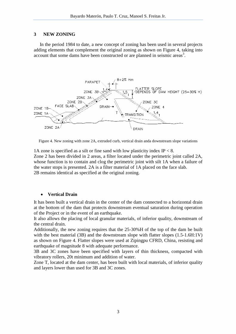
Figure 4. New zoning with zone 2A, extruded curb, vertical drain anda downstream slope variations
1A zone is specified as a silt or fine sand with low plasticity index IP < 8.
Zone 2 has been divided in 2 areas, a filter located under the perimetric joint called 2A,
whose function is to contain and clog the perimetric joint with silt 1A when a failure of
the water stops is presented. 2A is a filter material of 1A placed on the face slab.
2B remains identical as specified at the original zoning.
Vertical Drain
It has been built a vertical drain in the center of the dam connected to a horizontal drain
at the bottom of the dam that protects downstream eventual saturation during operation
of the Project or in the event of an earthquake.
It also allows the placing of local granular materials, of inferior quality, downstream of
the central drain.
Additionally, the new zoning requires that the 25-30%H of the top of the dam be built
with the best material (3B) and the downstream slope with flatter slopes (1.5-1.6H:1V)
as shown on Figure 4. Flatter slopes were used at Zipingpu CFRD, China, resisting and
earthquake of magnitude 8 with adequate performance.
3B and 3C zones have been specified with layers of thin thickness, compacted with
vibratory rollers, 20t minimum and addition of water.
Zone T, located at the dam center, has been built with local materials, of inferior quality
and layers lower than used for 3B and 3C zones.

Bayardo Materón, Paulo T. Cruz, Manoel S. Freitas Jr.
4
4 ESTABILITY
The inclusion of local materials of inferior quality, located downstream the drain,
does not affect the stability, since the wedge shear zone is located on 3B material which
has the best strength parameter (Angle φ).
A stability analysis methodology is discussed in Reference4, including acceleration
parameters applicable on seismic areas. Figure 5.
Figure 5. (CORREGIR ESTA FIGURA)
5 CONSTRUCTION PLANNING
An important aspect to be taken into account with the new zoning is the construction
planning of the CFRD. It is important to give priority at the construction of the plinth.
The plinth excavation should be done simultaneously with the excavation of the
diversion tunnels, so that after diversion the only excavation lacking is the river bed
area and the portion covered by the river on both banks.
In places where the abutments are steep, planning and construction of the plinth can be
executed during placement of rockfill5.
The volume of plinth excavation and concrete placing are relatively small. There is a
tendency on the part of contractors to leave these activities after diversion, causing
delays that affect the execution of the work in general.
6 BEHAVIOR OF NEW CFRD’s
Following is described some aspects of modern dams where have applied, partially
or completely, the concept of the new zoning6.
El Cajón, 188m, México. Rockfill: Ignimbrite.
El Cajón Project was built by the COMISIÓN FEDERAL OF MÉXICO – CFE, with
modern criteria, compacting thin rockfill layers (3B = 0.60) and (T=1.00m) with heavy
compactor rollers, 20 t, with generous application of water, > 200 l/m³.
The maxim rockfill deformation, at the center of the dam before reservoir filling, was
0.75m which represents to only 0.40% H.

Bayardo Materón, Paulo T. Cruz, Manoel S. Freitas Jr.
5
During construction of the slabs was observed that the back pressure from water
accumulated at the lowest point of the plinth, produced displacements of the slab which
were corrected by drilling holes to relieve pressure.
Figure 6. El Cajón Dam. Rockfill deformation before reservoir filling.
Figure 7. El Cajón Hydroelectric Project – México Figure 8. Rockfill placement with water application
The behavior of the dam has been excellent.
Reventazón, 130m, Costa Rica – Fill: Riverbed gravels, conglomerates,
consolidated breccias.

Bayardo Materón, Paulo T. Cruz, Manoel S. Freitas Jr.
6
Dam Reventazón CFRD is being built by the INSTITUTO COSTARRICENSE DE
ELECTRICIDAD, ICE, using riverbed gravels and mixtures with conglomerates and
consolidated breccias, of inferior quality, to obtain the required volume for the dam.
Fill 3B is riverbed material placed in 0.60m layers. Zone T is a mixture of gravels and
consolidated breccias in the ratio 2:1. 3C material is the product of alluvial gravels
mixed with conglomerates in the ratio 3:1. The materials located downstream of the
dam axis, are protected by a vertical drain located at the center of the dam connected to
a horizontal drain at the dam bottom. Figure 9.
An interesting aspect of this dam is that processed materials as the drain and transitions
rockfill (2B and 3A) were placed efficiently with metallic molds as illustrated in Figure
10.
Figure 9. Reventazón Dam – Zoning
Figure 10. 2B zone placing with metallic mold
The observed deformations of the fill are consistent with the predictions of the Project.
Porce III, 150m, Colombia. Rockfill: Igneous and schists
The Porce III CFRdam was built by EMPRESAS PÚBLICAS DE MEDELLÍN - EPM,
with material from the structures excavation (underground and spillway) mainly

Bayardo Materón, Paulo T. Cruz, Manoel S. Freitas Jr.
7
igneous and metamorphic schists from the spillway excavation. The processed materials
including (2B and 3A) the vertical drain were produced by crushing underground
igneous material of good quality. Main rockfill was built with schists presenting high
values of Los Angeles Abrasion8 closed to 60%.
Material was well compacted in thin layers (0.60m – 0.80m) with Heavy Compactor
rollers and water application. Central maximum deformation was lower than 1.0%H.
During construction of the lower face slabs was not presented back pressure, because
the vertical and horizontal drains worked well drawing the compaction water
downstream.
Figure 11. Porce III. Central vertical drain and zoning
Figure 12. Porce III - Schists rockfill placing Figure 13. Porce III- Face slab view
The dam has an adequate behavior according to the design premises.
Mazar, 166m, Ecuador. Rockfill: quartzitic, cloritic and sericitic schists
Mazar Dam was built by CORPORACIÓN ELECTRICA DEL ECUADOR – CELEC
E.P. with schistose materials in thin layers of 3B (0.50m) and 3C (0.80m) with 6 passes

Bayardo Materón, Paulo T. Cruz, Manoel S. Freitas Jr.
8
of a heavy compactor vibratory roller and water addition of 300 l/m³. A central drain,
slightly inclined downstream, was placed to protect downstream material 3C against
saturation.
Figure 14. Typical zoning of Mazar CFRD
Figura 15. Mazar – Downstream view
COMPLEMENTAR TEXTO (FREITAS)

Bayardo Materón, Paulo T. Cruz, Manoel S. Freitas Jr.
9
Chaglla, 211m, Peru. Rockfill: gravels and limestone rockfill
Chaglla dam is being built by EMPRESA DE GENERACIÓN HUALLAGA S.A.,
using the Huallaga river gravels and deposits of calcareous material (limestone) close to
the dam site. The specifications follow the selection of modern thin layers, addiction of
water and heavy vibratory compactors with a weight of 20 t minimum.
The design incorporates a central vertical drain and a zone T of granular material of
inferior quality with fines close to 15% passing the No. 200 sieve.
However,during the explotation of this source a substantial reduction of fines have been
noted to values close to 5% as a maximum.
3B materials (gravels or limestone) are compacted in 0.60m layers.
The Chaglla narrow valley has required the design of special waterstops to offset
potential high perimetric joint movements9.
Figure 16. Chaglla Dam cross section
Vista frontal del relleno aguas abajo y plintos
Figure 17. Face slab construction

Bayardo Materón, Paulo T. Cruz, Manoel S. Freitas Jr.
10
New projects such as Coca Codo Sinclair in Ecuador and in Patagonia on the Santa
Cruz river, Argentina, are considering the new zoning using a vertical drain and local
materials compacted in thin layers.
7 CONCLUSIONS
A new zoning of CFRDs, has been used to complement the original zoning of
Detroit 1984. New zoning incorporates modifications as follows:
Dam layers are thinner than original ones. They are compacted by heavier rollers
generating high modulus of compressibility.
A central vertical drain has permitted to use rockfills of inferior quality
downstream of the central drain. This drain prevents saturation of downstream
material making the dam stable even during seismic events.
Upper downstream slope has been designed flatter to give better capacity of
stability in seismic zones.
Special water stops have been designed to provide more capacity to resist greater
movements in very narrow valleys.
These improvements have allowed building higher CFRDs with excellent
performance from a technical and economical stand point.
REFERENCES
[1] J.B. Cooke and J.L. Scherard, Concrete Face Rockfill Dam: II.Design, Journal
of Geotechnical Engineering A.S.E. Vol. 113, United States (1987).
[2] F. Resende and B. Materón, Itá Method – New Construction Technology for the
Transition Zone for CFRD’s, CIGB ICOLD Proceedings International Symposium on
CFRD’s, Beijing, China (2000).
[3] B. Materón, Vertical Drains as a Safety Measure for CFRD’s, Water Power and
Dam Construction, England, November (2013).
[4] B. Materón and G. Fernandez, Considerations on the Seismic Design of High
Concrete Face Rockfill Dams (CFRD’s), 2nd
International Symposium on Rockfill
Dams, Rio de Janeiro (2011).
[5] P.T. Cruz, B. Materón, M. Freitas, Concrete Face Rockfill Dams, Barragens de
Enrocamento com Face de Concreto, Editoria Signer - Oficina de Textos, São Paulo,
Brasil (2009).
[6] B. Materón, Introduction of Vertical Drains as a Safety Measure for CFRD’s
with New Materials Located in Seismic Areas, CHINCOLD, 3rd
International
Symposium on Rockfill Dams, Kunming, China (2013).

Bayardo Materón, Paulo T. Cruz, Manoel S. Freitas Jr.
11
[7] H. Marengo, Monitoring of El Cajón Dam, Lisbon, Portugal Conference,
February (2007).
[8] Ingetec S.A., Proyecto Hidroeléctrico Porce III – Presa Relleno y Cara de
Concreto – Consultant Meeting No. 12, Medellín, Colombia, (2010).
[9] A.M. Calcina, et al, Chaglla CFRD – Main Design Features, CHINCOLD, 3rd
International Symposium on Rockfill Dams, Kunming, China (2013).