evolution of rfid systems - mit opencourseware · 1/23/2006 · 23 january 2006 evolution of rfid...
TRANSCRIPT

23 January 2006 Evolution of RFID systems 11
Evolution of RFID SystemsPeter H Cole
Adelaide Auto-ID Laboratory

23 January 2006 Evolution of RFID systems 2
Objectives
• Title is to capture notions of
• How RFID systems have evolved under constraints
• How they might evolve under research
• If desired, some details of research at Adelaide

23 January 2006 Evolution of RFID systems 3
Topics
• RFID regulations
• Antenna issues• Propagation studies• Protocol issues
• Higher functionality tags• Signalling waveform design• Security and authentication

23 January 2006 Evolution of RFID systems 4
RFID regulations
• Regulators– ITU Regions– ]FCC, EN, Other national bodies
• Usage of radio spectrum and bands• Regulatory standards
– ISO ETSI • Australia experimental licence• Listen before talk regulations• Synchronisation

23 January 2006 Evolution of RFID systems 5
Antenna issues
• Electromagnetic theory• Coupling calculations• Bode Fano Limit• Antennas for dual frequencies• Antenna size and frequency constraints• Antennas in or near metal• A small antenna example.
23 January 2006 Evolution of RFID systems 6
Propagation studies
• Electromagnetic theory• Near and Far fields• Near and far field coupling theories• Some fundamental constraints• Dense RFID reader studies.

23 January 2006 Evolution of RFID systems 7
Protocol issues
• Concept of a protocol• Tag talks first and reader talks first protocols• Constraints on protocols
– UHF signalling– HF signalling
• Adaptive round concepts• EPCglobal C1G2 protocol• Approaches to advanced HF protocols
– Can HF sustain heavy signalling?– Ways it might
23 January 2006 Evolution of RFID systems 8
Higher functionality tags
• Autonomously networking tags• Merging of EAS and data tags • Trigger circuits for battery tags
– Low power approach• Issues and experiments
– Zero power approach• Application to theft detection
23 January 2006 Evolution of RFID systems 9
Security and Authentication
• Methods for providing security• Levels of security• Burdens on chip design• Burdens on signalling systems

23 January 2006 Evolution of RFID systems 10
Overview of Adelaide research
• Personnel• Classification of projects• Detector research • Data logging reader research• Dense reader environment research• Privacy and security research• Trigger circuit research• Publications

23 January 2006 Evolution of RFID systems 1111
Antenna Issues
Peter H ColeAdelaide Auto-ID Laboratory

23 January 2006 Evolution of RFID systems 12
Outline
• Electromagnetic theory
• How antennas work (approximately)
• Near and far fields
• Near and far field coupling theories
• Significant conclusions about performance
• Bode-Fano limit for efficiency
• Some simple tag designs

23 January 2006 Evolution of RFID systems 13
Laws in differential form
0
-
=⋅∇=⋅∇
∂∂
+=×∇
∂∂
=×∇
BD
DJH
BE
ρt
tVortex
Source

23 January 2006 Evolution of RFID systems 14
Boundary Condition: electric field
Charge
Conducting surface
Electric field

23 January 2006 Evolution of RFID systems 15
Boundary Condition: magnetic field
Conducting plane
ordisplacement current
Magnetic field

23 January 2006 Evolution of RFID systems 16
The basic laws: how they work
• Gauss’s law–Electric flux deposits charge–Electric field cannot just go past a conductor, it must turn and meet it at right angles
• Faraday’s law–Oscillating magnetic flux induces voltage in a loop that it links
V+_
B
23 January 2006 Evolution of RFID systems 17
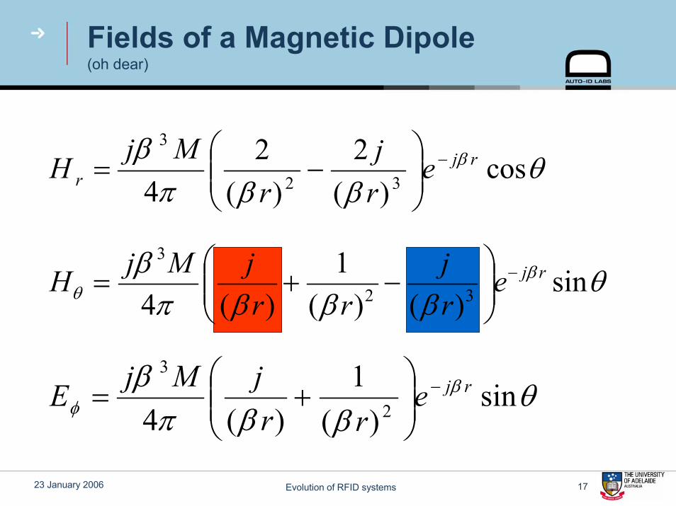
Fields of a Magnetic Dipole(oh dear)
θββπ
β β cos)(
2)(
24 32
3rj
r erj
rMj
H −⎟⎟⎠
⎞⎜⎜⎝
⎛−=
θβββπ
β βθ sin
)()(1
)(4 32
3rje
rj
rrjMjH −
⎟⎟⎠
⎞⎜⎜⎝
⎛−+=
θββπ
β βφ sin
)(1
)(4 2
3rje
rrjMjE −
⎟⎟⎠
⎞⎜⎜⎝
⎛+=

23 January 2006 Evolution of RFID systems 18
Near and far field coupling theories
• Common feature: a label driving field is created, how much signal can be extracted?
• In the near field of the interrogator, the driving field is mostly energy storage, and the amount radiated does not affect the coupling, but does affect the EMC regulator.
• Various techniques to create energy storage without radiating are then applicable.
• Some theorems on optimum antenna size are of interest.
• In the far field of the interrogator, the relation between what is coupled to and what is regulated is more direct, and such techniques are not applicable.

23 January 2006 Evolution of RFID systems 19
Far field coupling theory
rerr SgASPπλ
4
2
==
2t
4areaunit per flow Power
rPg t
π=
areaunit per flow Power ×= err AP
πλ
4
2r
ergA =
2
4 ⎟⎟⎠
⎞⎜⎜⎝
⎛=
rgg
PP
trt
r
πλ

23 January 2006 Evolution of RFID systems 20
Near field coupling theory
[ ][ ]position label at theor interrogat by the createdpower reactive ofdensity Volume
circuitedshort isit whencoil label untuned thein flowingpower Reactive=cV
[ ][ ]position label at theor interrogat by the createdpower reactive ofdensity Volume
coil creation fieldor interrogat theofinductor thein flowingpower Reactive=dV
211
2 QQVV
PP
d
c=

23 January 2006 Evolution of RFID systems 21
Measures of exciting field
rv SW β=
In the far field
23 January 2006 Evolution of RFID systems 22
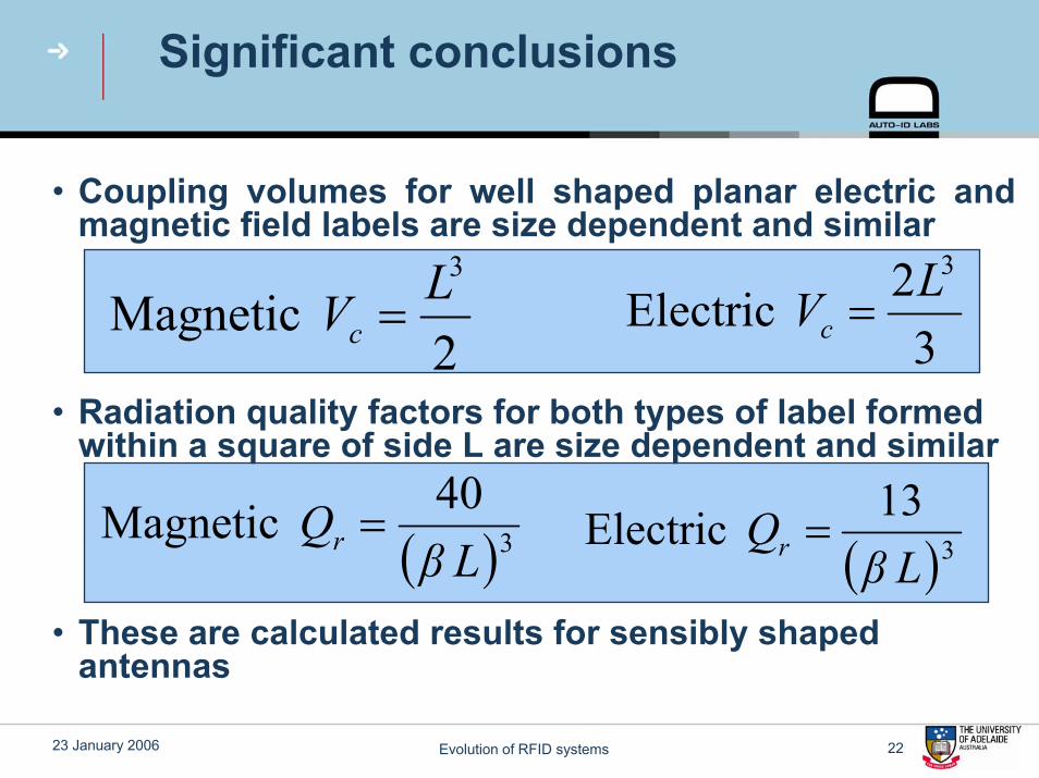
Significant conclusions
• Coupling volumes for well shaped planar electric and magnetic field labels are size dependent and similar
• Radiation quality factors for both types of label formed within a square of side L are size dependent and similar
• These are calculated results for sensibly shaped antennas
( )340 MagneticLβ
Qr = ( )313 ElectricLβ
Qr =
32 Electric
3LVc =2 Magnetic
3LVc =
23 January 2006 Evolution of RFID systems 23
Optimum operating frequency
The optimum frequency for operation of an RFID system in the far field is the lowest frequency for which a reasonable match to the radiation resistance of the label antenna can be achieved, at the allowed size of label, without the label or matching element losses intruding.

23 January 2006 Evolution of RFID systems 24
Bode-Fano Limit
VS
RS
ZIN
LOSSLESSMATCHINGNETWORK
RC
RCπ dω 1ln
0
≤Γ∫
∞

23 January 2006 Evolution of RFID systems 25
Bode-Fano Limit (cont)
Ref
lect
ion
coef
ficie
nt, |
|Γ
Angular frequency, ω
1
| |Γ inband
ω ω1 2∆ω
fRC21
inbande ∆−
≥Γ

23 January 2006 Evolution of RFID systems 26
Bode-Fano Limit (cont)
• Allocated bandwidths for RFID:
• Others:China: 917 – 922 MHz (Temporary license can be applied)Australia: 918 – 926 MHz

23 January 2006 Evolution of RFID systems 27
Bode-Fano Limit (cont)
• 3 different cases considered:
Ref
lect
ion
coef
ficie
nt, |
|Γ
Frequency, f (in MHz)
1
| |Γ max
902 928∆f
(a)
Ref
lect
ion
coef
ficie
nt, |
|Γ
Frequency, f (in MHz)
1
| |Γ max
865 868 902 928 950 956∆f1 ∆f2 ∆f3
(b)
Ref
lect
ion
coef
ficie
nt, |
|Γ
Frequency, f (in MHz)
1
| |Γ max
∆f865 956
(c)
23 January 2006 Evolution of RFID systems 28
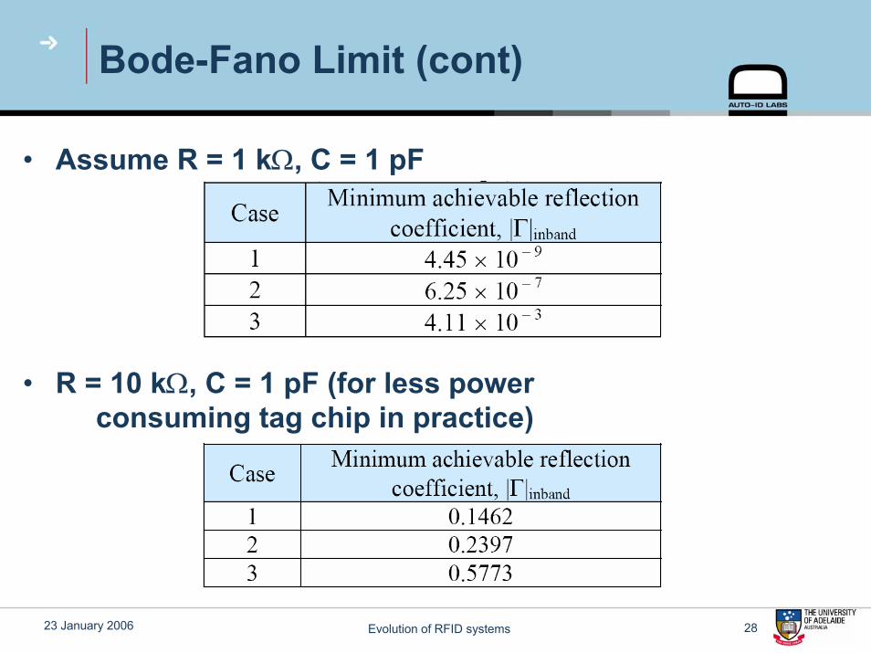
Bode-Fano Limit (cont)
• Assume R = 1 kΩ, C = 1 pF
• R = 10 kΩ, C = 1 pF (for less powerconsuming tag chip in practice)

23 January 2006 Evolution of RFID systems 29
A Simple RFID Tag
• Consists of a circular loop antenna with a very simple matching network
FRONT REAR

23 January 2006 Evolution of RFID systems 3030
Higher Functionality Tags
Adelaide Auto-ID Laboratory
23 January 2006 Evolution of RFID systems 31
Interesting questions
• Merging of EAS and Data tags
• Turning on battery operated tags– Low power consumption– Zero power consumption
23 January 2006 Evolution of RFID systems 32
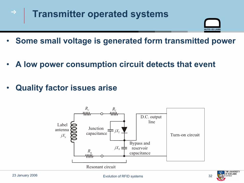
Transmitter operated systems
• Some small voltage is generated form transmitted power
• A low power consumption circuit detects that event
• Quality factor issues arise
Junction capacitance
Bypass and reservoir
capacitance
Resonant circuit
Label antenna
D.C. output line
jXs
jXB
jXl
Rr
Ra
Rl

23 January 2006 Evolution of RFID systems 33
Experiments on detuning
1MΩ
10kΩ 11.5pF
Rectified voltage to Oscilloscope using a BNC connector
RF IN through an SMA connector

23 January 2006 Evolution of RFID systems 34
Low and high power sweeps
23 January 2006 Evolution of RFID systems 35
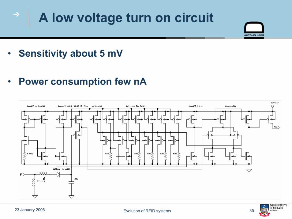
A low voltage turn on circuit
• Sensitivity about 5 mV
• Power consumption few nA

23 January 2006 Evolution of RFID systems 36
Zero power turn on concept
• Low frequency magnetic field vibrates a magnet
• Piezoelectric converter generates about a volt

23 January 2006 Evolution of RFID systems 37
Electroacoustic conversion modelling
• Variables are – Torque and angular displacement, – charge and voltage
• Electroacoustic parameters for substances known
• Parameters for structures are calculated therefrom
Electroacousticenergy conversion
system1 2
+
_
q
+
_

23 January 2006 Evolution of RFID systems 38
Eletroacoustic conversion
• Structural parameters appear below
⎥⎦
⎤⎢⎣
⎡⎥⎦
⎤⎢⎣
⎡=⎥
⎦
⎤⎢⎣
⎡τφ
θ PP
PP
CCCCq
2221
1211

23 January 2006 Evolution of RFID systems 39
Structure analysed
P
F
F
h
tp
w
Magnet Piezoelectric material
tm

23 January 2006 Evolution of RFID systems 40
Result
• Turn-on voltage depends on– Driving magnetic field– Electroacoustic parameters– Some resonance quality factors
effJSmeffTO CC
CMvQkV22
222
220
22 1H)( µ=