evaluation of rubber-asphalt mixture used as a stress...
TRANSCRIPT

TE :;HNICAL RE~PORT STANDARD T1 TLE PAGE 1. Report No. 2. Govern. Accession No. 3. Recipient's Catalog No.
FHWA/TX-79/43+529-lF
4. Title and Subtitle 5. Report Date
EVALUATION OF RUBBER-ASPHALT MIXTURE USED AS A December, 1979
STRESS RELIEVING INNER LAYER 6. Performing Organization Code
7. Author(s) 8. Performing Organ. Report No.
John A. Blasienz 529- 'IF Arthur A. Geick
9. Performing Organization Name and Address 10. Work Unit No. Texas State Department of Highways & Public Trans. District 17 11. Contract or Grant No. Bryan, Texas 77801 DOT-FH-15-226
13. Type of Report & Period Cov. 12. Sponsoring Agency Name and Address Final
Texas State Dept. of Hwys. & Public Trans. July 31, 1977 - Jan. 31, 1979 Transportation Planning Division P. 0. Box 5051 14. Sponsoring Agency Code Austin_, Texas 78763
15. Supplementary Notes Work done in cooperation with U.S. Department of Transportation, Federal Highway Administration FHWA Experimental Project TX77-04
16. Abstract
Critical shortages and spiraling costs of construction materials has necessitated investigation into new procedures which utilize readily available, recyclable materials which are normally wasted. One such method is the placement of ground tire-rubber mixed with asphalt cement as a stress relieving inner layer to be used on severely cracked amdistressed pavements to prevent, or retard, reflective surface cracking in new pavement. This report deals with a demonstration study on SH 36 in Washington County which monitored the performance of the asphalt-rubber inner layer when in place and discusses the construction techniques used in its application.
The rubber was mixed with asphalt in a distributor and applied as a seal coat directly on the existing pavement, except in severely damaged areas which required prior patching. Two inches of asphalt stabilized base was placed on the rubber asphalt seal except in certain test sections where the rubber asphalt mixture was exposed to direct traffic.
p. Key Words 18. Distribution Statement reflective cracking stress relieving inner layer No restrictions crack retardation
~9. Security Classif. (of this report) 20. Security Clas). (of this page
21. No. of Pages 22. Price
_ Unclassified Unclassified 52
' . Form DOT 1700.7 (8-69)

EVALUATION OF HOT ASPHALT-RUBBER MIXTURE USED AS A STRESS RELIEVING INNER LAYER
FINAL REPORT FOR
DEMONSTRATION STUDY
ON
STATE HIGHWAY 36 WASHIM3TON COUNTY
TEXAS
CONTROL: 186·5
PROJECT SUPERVISION
ARTHUR A. GEICK, SUPERVISING RESIDENT ENGINEER
FRANKLIN HAARMEYER, ENGINEERING TECHNICIAN V
REPORT PREPARED BY
JOHN A. BLASIENZ, DISTRICT CONSTRUCTION ENGINEER
ARTHUR A. GEICK, SUPERVISING RESIDENT ENGINEER
STATE DEPARTMENT OF HIGHWAYS & PUBLIC TRANSPORTATION
DISTRICT 17
BRYAN, TEXAS
IN COOPERATION WITH
U. S. DEPARTMENT OF TRANSPORTATION FEDERAL HIGHWAY ADMINISTRATION
ii
...
.. ~
-'• -'· .....
.,. ....
It
"'
•' ,., .,.r Mi2'
01
lb
, .. Tblto fl 01
c 11'1 Ql
"'' ... ~d,
.,
A,roliMitl Cemrarai1111 te Mttric: M11a•re•
...., .. _
"'C.... """'' fftil••
_....._ _ .... -·""'· ............. -· -·· """""' lhort tOftS
tZOOO tbl
.......... ubt••fJIIDIG'I• Uutd ounces ·-P""' -· gal tons cub•<. fHI
cutuc Vil"'d!&
. ......,., lENGTH
·z.• )0
o.t 1.1
AIIEA
••• 0.18 0.1 2.f
••• MASS (wtitliltl
71 ..... o.t
'VOLUME
.. 1i :10 0.2• 0.17 0.!15 u 0.03 0.16
TEMPERATURE (txnt)
F abn!nfite'tt
tflll"'t'll8f•tute s,g '' .. """ sub'fra<:1tnt
l11
h Fi••
c.tt""'t•• cet~:tirneuwa -·· .. , .........
...... c.-...... ...... ""'"'' ...............
..,_elui..C.•t
he<•••
gr .... . .. ..... . ~-·
fftilhUMrt
mfUititen.
milhhters hb!rt
htera hten lltf!'fS
cub•c met«W s
rub1c ••..-tet'S
Celstus
t~ratute
., .... em
""' .. ....
~ ... ' .... ..,., ...
I ~g
"'' "'' tnl
' ,, ,J
"(
METRIC CONVERSION FACTORS
"'
•
..
.. ..
.. i
!:
~
=- !:
!!!
~
:!:
..
s, ••••
... .,
.. ~ ...
~ ,.t ~l ...
I kg
,., I
I .,J
m'
"c
A,re•i•eta Cenersi .. t lrt• Metric Mlltlrll
w ... , ••••••
,..,.thrnetett
c..-.hffWtert -... ....... , ....... .
-·--· --· ..,.,. ... u .... . ....,, ••• 110 .... .,J,
....... , ~ LE•&TH
o.oc o.• l.l u • ••
AilE A
0.11 1.2 o.• 2.1
MAII( ..... t)
-· ····"'" ·-•118DOql
.............. htllrt
hters ..... ,. cubtc: ,...,.,.
cutnt mtt••
O.Gll 2.Z 1.1
'VOLUME
a.u Z.l 1.01 0.21
l!i l.l
TEII,EitATUIIE (llttl)
Celstul ,..,...,.,.tn tllit-32!
Ta ,_,
-· -.... , ..... ... ....
---_, .... _ ...... --" ......... .- ....
,....,_ . ..... _,. ....... .... c .... -··-· , .... _;, -- .,
•r 3Z 9 .. 1 1112
-~f .. 1 ~ I I .r.o 1 I 1 •.o. f . ·~o. 1 1 ·~o ••• ~ L I f 1 I t t I r I f
-40 -70 t' ~0 40 tO • 10 I
ec '1 •c
. .....
ilt ... It
"' ...
""' ,; .. J
-• "• .. ... .. . .. , .,.,
••

-The contents of this report reflect the views of the authors who are
responsible for the facts and accuracy of the data presented herein. The
contents do not necessarily reflect the official views or policies of the
Federal Highway Administration. This report does not constitute a standard,
specification, or regulation.
iv

Table of Contents
Metric Conversion Table •••• Disclaimer Statement ••••• Tab 1 e of Ill us trati ons . • . . Chapter I - Project Background . • . • Chapter II - Design •••.•••••. Chapter III - Construction Phase Chapter IV - Conclusions •••• Six-Month Pavement Evaluation •• Twelve-Month Pavement Evaluation Eighteen-Month Pavement Evaluation S UrTJ11a. r y • • . • . . • • • • • • • •
Appendix 1 - Special Specification Item 3046
. . .
. . . .
Hot-Asphalt-Rubber Seal Coat •. . . . . . . . . . Appendix 2 - Standard Item 300, par 300.2(2) - Asphalt Cement
Appendix 3 - Standard Item 300, par 300. 2 {7) - Emulsions
Appendix 4 - Standard Item 304, par 304.4 - Grades of Aggregate
Appendix 5 - Standard Item 213, par 213.2 - Rolling Equipment .•
v
. iii iv vi 1 8
. . • . 12 37 38 39 40 41
43
. . . . 49
. . . . 50
51
52

Table of Illustrations
Picture 1 Core-of Pavement . 0 0 0 0 0 0 0 0 0 0 0 . . . . . . 0 0 0 2 Picture 2 Core of Pavement . 0 0 0 0 0 0 0 0 0 0 . 0 . 0 . 0 0 0 0 0 2 Picture 3 Core of Shoulder . 0 0 0 0 0 0 0 0 0 0 0 0 0 0 0 0 • 0 . 3 Picture 4 Close-up View of Asphalt-Rubber Seal Coat as Inner Layer . . . 0 . -. . 4 Picture 5 Pavement Surface Prior to Construction 6 Picture 6 Pavement Surface Prior to Construction . 0 . 0 0 . . . 6 Picture 8 Sahuaro Bear Cat Distributor . . . 0 0 0 0 . . 14 Picture 9 Distributor Instruments. . 0 0 0 0 0 0 . . 0 14 Picture 10 Distributor Nozzel Controls 0 0 0 0 15 Picture 11 Distributor Spray Bar 0 0 0 0 0 0 0 0 . 0 15 Picture 12 Rear View of Distributor Spray Bar . . 0 . 0 16 Picture 13 Seal Coat Application. 0 . 0 0 0 0 . . . . 16 Picture 14 Side View of Asphalt Pump. 0 0 0 0 . 0 0 . 0 . 0 0 . 17 Picture 15 Diesel Heating Unit on Distributor . 17 Picture 16 Bomag Aggregate Spreader . 0 0 0 0 19 Picture 17 Asphalt-Rubber Seal Coat Operation 0 0 0 0 19 Picture 18 Asphalt-Rubber Seal Coat Operation . 0 0 0 0 0 0 0 20 Picture 19 Conveying Ground Rubber into Distributor 20 Picture 21 Front-End Loader Removing Old Hot Mix. 0 0 0 . 0 22 Picture 22 Exposed Slag Aggregate Hot Mix . 0 0 0 0 0 0 0 22 Picture 23 Cleaned Slag Aggregate Hot Mix .... 0 0 0 . 23 Picture 24 Emulsion-Primed Slag Aggregate Hot Mix 0 0 0 0 23 Picture 25 Blade-Laid Hot Mix in Place. 0 0 0 0 0 0 . 0 0 24 Picture 26 Pavement Close-up prior to Priming 0 0 24 Picture 27 Pavement Close-up After Priming. 0 0 0 . . . . 0 0 0 0 . 0 25 Picture 29 Application of Sand-Asphalt Mixture. 0 0 0 . . 0 0 0 . 25 Picture 30 Application of Sand-Asphalt Mixture. 0 . 0 0 26 Picture 31 Ray-Go 2-84 Vibratory Roller . 0 0 . 0 0 0 0 0 0 . 0 . 26 Picture 33 Cut-out Pavement Section Showing Seal-Coat Thickness . 0 0 0 0 28 Picture 34 Wheel-Path Flushing of Rubber-Asphalt Seal-Coat . 0 0 0 0 28 Picture 35 Close-up of Flushed Pavement . 0 0 0 0 . 0 0 0 0 0 0 30 Picture 36 Collection of Mixture Samples from Distributor . 0 30 Picture 37 Calibrated bucket for Mixture Weight Determination 31 Picture 38 Primed Surface Prior to Sand-Asphalt Application • . . 0 0 0 0 0 33 Picture 39 Surface with Seal-Coat in Place 0 0 0 . 0 0 0 33 Picture 42 Section 212 Surface Prior to Seal-Coat . 0 . 0 0 0 0 0 . 34 Picture 43 Section 212 Surface After Seal-Coat. 0 34 Picture 44 Section 476 Surface Prior to Seal-Coat . 0 0 0 0 35 Picture 45 Section 476 Surface After Seal-Coat. 0 35 Picture 40 Section 476 Surface Prior to Seal-Coat . . . . . . 36 Picture 41 Section 476 Surface After Seal-Coat. . 36
- .
vi

. . .
HOT ASPHALT-RUBBER SEAL COAT
State Highway 36 Washington County District Seventeen
CHAPTER I
PROJECT BACKGROUND
The 1975-77 Consolidated High~ay Program included a project to recon-
struct the base and surface on a 12 mile section of SH 36 between Brenham
and the Yegua Creek.
This section, originally an 18-feet concrete pavement, had been widened
and reconstructed by a project completed in October, 1959. That project had
1
consisted of breaking the original concrete pavement, rolling the broken pave-
ment with a 50-ton roller, and overlaying the entire crown with a sandstone
subbase. A class 1 flexible base course, consisting of a crushed, hard,
local sandstone, was placed over the subbase; and approximately one inch of
asphaltic concrete pavement was placed for surfacing. No subgrade treatment
or stabilization was used in the rework project. Subsequently, one-inch
courses of cold-mix rock asphalt, slag aggregate hot-mix, and light-weight
aggregate hot-mix were placed at various intervals. Seal coats were also
applied on each of these courses as separate phases between the overlays.
(See Photos 1, 2, 3, and 4).
The project experience was that the flexible section was adequate but
the surface cracked in the travel lanes. Numerous and extensive alligator-
type cracking appeared on the cold-mix course at an early age, indicating
deflection, although there was little or no wheel path rutting. A seal coat
failed to seal or prevent a continuation of this cracking. The additional
one-inch hot-mix courses and seals continued to reflect the cracks. The

N
1
. ',
Core of pavement. Identifying from top to bottom is 2!.,;" asphalt stabilized base placed under this contract. The asphalt-rubber seal coat as an inner layer. l" layer of lightweight aggregate hot mix. A seal coat on top of 1" slag aggregate hot mix. A seal coat on 1" cold-mix rock asphalt. 1" of original asphaltic concrete pavement.
2

3
Core of shoulder. On top is a one course surface treatment, 2~" asphalt stabilized base and the asphalt-rubber seal coat. All placed as a part of this contract. Approximately 2" of lightweight aggregate hot mix.
3

4
Close view of the asphalt-rubber seal coat as a stress absorbing inner layer.
4

5
lightweight aggregate top course tended to spall and ravel sevenal~ Occasional
wet freezes caused the worst areas to shell out. Several areas were bladed
off and replaced with hot-mix by State Forces. These areas served well.
The intent of the proposed project was to place approximately five inches
of asphalt stabilized base over full crown width (42-feet) and overlay with one
inch of asphalt concrete pavement. The cost estimate was based on this typical
section; however, the inflationary period of 1973-74 occurred before the plans
were complete and suddenly there was only one-half enough money to perform the
proposed work. District and residency personnel were forced to consider
alternate, more economical, methods of construction. Several recycling
possibilities were considered, including:
1. Salvaging, crushing, and reusing the existing asphaltic concrete for use as the predominate aggregate in a hot, plant-mixed asphalt stabilized base to be relayed by machine. '
2. Salvaging the existing asphaltic concrete by scarifying and road processing; adding emulsion; and blade-laying as a cold-mix black base.
3. Same as (2) except using more exotic traveling hot-mixers.
4. Using cement as stabilizing agent in (2).
All of the above procedures were found to be costly and all would create
severe traffic-handling problems. All were of a character of a major re-
construction of the roadway facility.
On-site inspection of the roadway indicated that the flexible base course
of the roadway was adequate. MOst of the shoulder area was in satisfactory
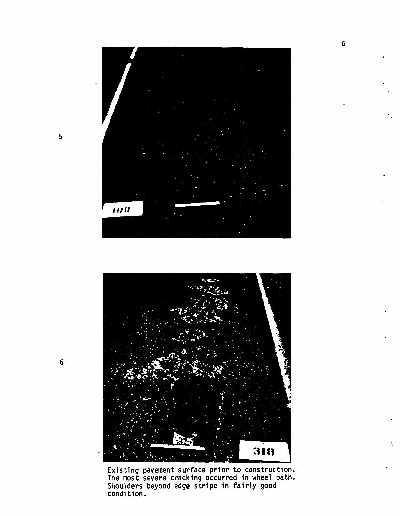
condition, with little or no cracking. It appeared that only about one third
of the surface area was severly cracked, mostly in the wheel paths, and that
only five percent would have to be removed and replaced prior to overlaying.
(See Photos 5 and 6). The conclusion was reached that, if the cracks could
be adequately sealed, a relatively thin overlay would restore the original
5
6
318
Existing pavement surface prior to construction. The most severe cracking occurred in wheel path. Shoulders beyond edge stripe in fairly good condition.
6

7
shape to the travelway and provide a satisfactory riding surface.
Past experience indicated that the usual seal coat would not do the job.
It appeared that same type of membrane would be required. The project required
a surface which would penetrate the cracks and maintain a seal when the base
was deflecting or moving. Because of the location and character of the road
way, it was also necessary to use a material on which traffic could be placed,
at least temporarily, as well as a material which could be overlaid. Slurry
seals, fat seals, and plastic membranes were considered. In the process of
evaluating the various alternatives for this project, FHWA Implementation
Package 73-1, "Rubber-Asphalt Binder for Seal Coat Construction", and a report
from the Arizona Department of Transportation entitled "Asphalt-Rubber Membranes,
Development, Use, Potential", were studied. These reports, plus discussions
with representatives of Texas A&M University (Dr. Bob Galloway), Texas Trans
portation Institute, and the Materials and Tests Division and the Planning
Division of the State Department of Highways and Public Transportation suggested
another alternative -- a asphalt-rubber mix which could be overlaid as a seal
to accomplish our desired objectives.
There were several small test sections in Texas where an asphalt-rubber
overlay had been placed as a part of various research projects; however, results
of the procedures would not be available for some time. Since the protection
and salvaging of the existing pavement was of utmost importance, it was essential
to begin construction prior to the winter months to avoid the possibility of
severe damage by a freezing rain. A decision was made to proceed with develop
ment of an asphalt-rubber specification and, contingent upon securing approval,
to proceed with the project using this new (to Texas) approach to sealing and
prevention of crack reflection.

CHAPTER 2
DESIGN
8
Special Specification 3046, "Hot Asphalt-Rubber Seal Coath, was prepared
following the format of Texas Highway Department 1972 Standard Specifications
for Construction of Highways, Streets and Bridges, Standard Specification Item
316, "Seal Coat". The new specification was patterned after Item 316 because
the materials proposed for use were relatively new in Texas, but the process
for application, except for mixing the asphalt and rubber, appeared to be very
much the same as for normal seal coat application. The development of the
major components of the Special Specification are explained below:
1. Description: This item is described as a surface treatment composed of a
single application of a hot asphalt-rubber material, covered with aggregate.
Two methods of mixing the reclaimed rubber and asphalt cement are allowed to
achieve the end result of producing a stress~relieving inner layer of a
flexible, resilient material with improved resistance to brittleness. These
properties will prevent the tendency for cracks in the old pavement to propagate
through new or additional layers of asphaltic concrete pavements or seal coats.
The two methods coincide with the methods being used in Arizona at that time.
2. Materials: The materials specified below are applicable to either method
of mixing reclaimed rubber and asphalt.
(1) Asphalt: The asphalt must meet the requirements of the Standard
Specification Item, "Asphalts, Oils and Emulsions". Plans require an AC asphalt
with the type to be specified by the Engineer.
(2) The ground vulcanized rubber is to be made from tires, ground to the
gradation requirements specified, depending on whether it will be used with asphalt,
kerosene and rubber or with asphalt, extender oil and combined rubber. It is to
be free from fabric, wire, cord, or other contaminating materials, except 4%

9
calcium carbonate. The gradation requirements and specifications were taken
from the Arizona Department of Transportation's specifications.
(3) The ground devulcanized rubber is to be made from truck tires and will
be both vulcanized and devulcanized. Grading requirements and specifications
were again based on Arizona Department of Transportation's specifications.
(4) Kerosene serves as a dilutent, prolonging the low viscosity of the
mix. A minimum boiling point of 350°F. is required, based on temperatures
necessary for mixing the ingredients.
(5) Extender Oil, if specified, is to be a high-flash, resinous type which
will prolong the desired viscosity of the blended materials.
(6) Prime Coat shall be either EA-llM or EA-103 as determined by the
Engineer. It is to serve as a crack sealer and prtme and to be applied to
the dry, cracked, light-weight hot mix. Emulsion was specified to permit
traffic to pass through the construction without being picked up by vehicles.
(7) Coverstone aggregate shall be of the type and grade specified in the
plans, meeting the requirements of "Aggregate for Surface Treatments (Class B) 11;
"Aggregate for Surface Treatment (Precoated)(Class B)"; or the Item "Aggregate
for Surface Treatment (Light Weight)". Precoated aggregate was specified to
prevent dust at the hot-mix plant and at the chip spreader and to prevent damage
to windshields of vehicles traveling through the construction project. Another
purpose of the precoating was to serve as a prime around the limestone coverstone
to insure that there would be no absorption from the rubber-asphalt mixture
which could result in stripping in the future. The large size coverstone was
-selected to allow the asphalt-rubber to be applied at a rate of 0.5 gallon per
square yard. The plan rate of application of the aggregate was 75 cubic yards
per square yard.
3. Equipment: The specifications required the distributor to be a self-propelled
10
pressure type with adequate pumps having separate power to circulate the asphalt
rubber mix. An agitation system was required which was capable of maintaining
the asphalt-rubber mixture in suspension and prevent the settlement of the
undissolved rubber. Temperature gauges were specified and are essential to
control mixing temperatures and establish mixing times. The aggregate heating
system specified must continually agitate while heating at a controlled temperature.
The aggregate spreader shall be a self-propelled, continuous feed type, which
will uniformly spread the aggregate.
Rollers must meet the requirements of the Item "Rolling", medium pneumatic
tire, Type A, up to 25 tons.
The broom must be a rotary, self-propelled power broom.
The aggregate heating system specified must continually agitate while
heating at a controlled temperature.
4. Construction Methods: Construction methods differ slightly for the two
methods of mixing and spreading reclaimed rubber and asphalt.
(1) Method I - Mixture of Asphalt, Kerosene and Rubber
Mixing: The specification requires that the asphalt-rubber components
be combined as rapidly as possible. The temperature of the asphalt shall be
between 350°F and 450°F which will result in 30-35 minutes of reaction time
after the addition of the rubber for the mix to reach the proper consistency
for application. The required proportions are 75% asphalt and 25% vulcanized
rubber by weight. This mixture is diluted with 5-\% to 7-\% kerosene to adjust
and maintain proper viscosity.
The specification requires the contractor to show proof
that his equipment can mix the asphalt-rubber to the proper consistency. This
is to assure good results if the Contractor has never placed hot rubber-asphalt
before or if the Contractor desires to introduce untriedequipment.
Spreading: In this paragraph the specification outlines haw the
previously described materials are placed on the prepared surface of the roadway.

11
The width of application of the bot asphalt-rubber material is limited to 13
feet. The asphalt-rubber material shall not be applied when the air temperature
is below 60°F and falling but may be applied when the air temperature is 50°F
and rising.
The specifications require that the cover aggregate be preheated to a
0 0 temperature between 290 F and 350 F in order to remove surface moisture from
the stockpiled aggregate and to allow additional time for rolling and seating of
the aggregate in the asphalt-rubber mixture, if placed during cool weather.
(2) Method II - Mixture of Asphalt. Extender Oil and Combined Rubber
Mixing: The specifications require a proportinate mixture of approx-
imately 75% asphalt and 25% combined rubber. The proportion of combined rubber
by weight shall be 60% ground vulcanized rubber and 40% devulcanized rubber. The
proportion of asphalt to extender oil is approximately 85% to 15%. The mixture
is to be heated to a temperature not less than 400°F. The resulting blend of
materials will have an absolute viscosity of approximately 800 poises at 140°F.
S_preading: The paragraph "Spreading" is identical to the procedure
0 0 under Method I except that the temperature is increased to 350 F to 450 F.
5. Measurement: The measurement of the asphalt-rubber mixture is specified
to be at the point of application in gallons at the applied temperature. The
quantity to be paid for is the amount requested by the Engineer, which is normal
for seal coat application. The aggregate will be measured in vehicles when
applied to the road. All rolling will be paid for by the hour.
6. Pa~ent: This paragraph refers to the method of measurement in paragraph 5.
lt states that payment will be at the unit price bid for the various items of
work involved, such as "Hot Asphalt-Rubber", "Aggregate", and''Rolling". Payment
under these items is the full compensation for the work specified.

1. DESCRIPTION
CHA.PrER 3
CONSTRUCTION PHASE
Bids were received on October 14, 1976, with Jones G. Finke, Inc. of
Sealy, Texas, the successful bidder.
12
Work was to be in accordance with Special Specification Item 3046, "Hot
Asphalt-Rubber Seal Coat". The specific materials furnished, equipment used,
and construction techniques are described as follows:
2. MATERIALS
The contractor elected to use Method I, the mixture of asphalt, kerosene,
and rubber. The vulcanized rubber was made from ground truck and bus tires by
ATLOS Rubber, Los Angeles, California, and met the gradation requirements of
0-5% retained on a No. 16 sieve and 90-100% retained on a No. 25 sieve.
The Asphaltic material selected by the Engineer was an AC-5 supplied by
Exxon Company of Baytown, Texas. It met specification requirements for Item
302, "Aggregate for Surface Treatments" for precoating. and for 3pecial Specifi
cation No. 3046, "Hot Asphalt-Rubber Seal Coat".
Class B, Type PB, Grade 3 aggregate was specified. General notes of the
plans required the aggregate to have a minimum Polish Value of 33 when used as
a surface or finish course. The contractor obtained a crushed limestone
aggregate from Texas Crushed Stone Company in Georgetown, Texas and precoated
the aggregate in his dryer-drum plant on the project with 0.6% asphalt, Type AC-5.
The kerosene was furnished by SahuarG Petroleum and Asphalt Company of
Phoenix, Arizona, and had a minimum boiling point above 350°F.
The prime c·oat selected by the contractor was the emulsion EA•llM, supplied
by Texas Emulsions, Port Neches, Texas, and met requirements for Item 310,
"Prime Coat."

13
3. EQUIPMENT
The Sahuaro Petroleum and Asphalt Company of Phoenix, Ari;ona, furnished
Bear cat distributors with 4,500 gallon capacity, capable of heating and mixing
the asphalt, rubber, and kerosene and applying the mix to the road. (See Photo 8).
These distributors were equipped with sophisticated instruments in the cab to
assist in controlling the mixing and application of the asphalt-rubber mixture
on the road. An accurate on-board electronic fifth-wheel scale allowed the
operators to weigh their loads at any time from within the cab. Project inspec-
tors confirmed the accuracy of the on-board scales by weighing the distributors
empty and then weighing partial loads, using certified public scales, and comparing
the results with the on-board scales. A tachometer and an odometer controlled
the rate of application of the asphalt-rubber. Toggle switches within the cab
allowed the operator to open and close individual nozzels on the spray bar to
vary the width of application. (See Photos 9 and 10). The spray bar itself was
capable of being extended a maximum of 14 feet. The distributors were equipped
with three Jones No. 5 nozzels (approximately 3/16") per foot of spray bar,
operating at approximately 35 psi pressure. (See Photos 11, 12, and 13),
The pump used was a Deutz 90-hp, five-sylinder, air cooled German-made
diesel. It was capable of developing up to 50 pounds by-pass pressure when
cleaning the nozzels with kerosene or diesel. (See Photo 14).
The Bear cat distributors used a high-pressure diesel burner to beat the
asphalt-rubber. The burner was capable of raising the temperature of 2,800
0 gallons of AC-5 asphalt approximately 110 F per hour. (See Photo 15). An eight-
- inch tube traversed the entire length of the tank.
The mixing of the asphalt and rubber and maintaining the rubber in suspension
was accomplished by the use of a 15 inch screw type agitator which works as an
auger, moving materials around in the tank until mixed.

8
9
SAHUARO Petroleum & Asphalt Company's Bear Cat Distributor
Instruments inside cab of distributor. Shows tachometer, speedometer, etc.
14

10
11
Toggle switches inside cab for controlling nozzles on spray bar, pressure guages, etc.
Distributor's spray bar with Jones No. 5 nozzels.
15

12
13
Rear view of Bear Cat distributor and spray bar.
-Application of asphalt-rubber seal coat using some nozzels.
16

14
15
Side view of Deutz asphalt pump on distributor.
Diesel burner for heating asphalt rubber in distributor.
17

18
The aggregate heating system was the contractor's Boeing Dryer-Drum type
of hot-mix plant located on the project. The aggregate spreader was a Bomag.
(See Photo 16).
The rollers used were a 25-ton with an individual wheel .load of 3,200
pounds and tire pressure of 70 psi, and a 35-ton which had a wheel load of
6,800 pounds per tire at a pressure of 80 psi. Both rollers were pneumatic
tired, self-propelled rollers. (See Photos 17 and 18). The broom was a self-
propelled Broce.
4. CONSTRUCTION METHODS
(a) Mixing Asphalt, Kerosene and Rubber: The Hot Asphalt-Rubber Seal
operations began on April 12, 1977, with Sahuaro Petroleum and Asphalt Company
of Phoenix, Arizona performing the mixing operations. The AC-5 asphalt was
0 0 loaded into the distributor at a temperature of 315 F to 325 F from the contract-
Qr's 25,000 gallon storage tank. The asphalt was then heated in the distributor
to 380°F - 390°F by use of the diesel burner.
The ground vulcanized rubber, which was shipped in 60 pound bags on pallets,
was added to the distributor by means of a small agricultural-type conveyor belt.
(See Photo 19). The addition of the rubber to the distributor caused the temperature
0 0 of the asphalt to drop about 50 F or to a temperature of 330 F. At this stage,
the asphalt composed 75% of the mixture and the rubber accounted for 25%.
At this point, the asphalt-rubber mixture has formed the residual material I
which will be the resiliant flexible, stress-relieving layer of material designed
by the specification. For this reason, all prospective bidders were cautioned
that the mixture must contain the 751. (plus or minus 21.) of asphalt and 251. (plus
or minus 2%) of the rubber.
The asphalt and rubber were mixed for approximately 40 minutes after all
rubber was added until it reached the desired consistency. The temperature
remained around 330°F. The mixture was then diluted with kerosene and was ready

16
17
Bomag aggregate spreader.
Asphalt-rubber seal coat operation. 25-ton pneumatic tired roller follows.
19

18
19
35-ton pneumatic tired roller farther behind. Rollers must travel very slow so as not to disturb aggregate.
• r f
•••
Ground rubber from ATLOS Rubber, Los An~eles, California, being carried on agricultural conveyor belt into distributor.
20

21
for application to the roadway. It should be noted that the actual amount of
kerosene required depends upon the atmospheric temperature, and higher tempera
tures require less kerosene.
(b) Prime Coat: To prepare the surface prior to applying the hot asphalt
rubber seal coat, areas of old light-weight hot mix which were sliding due to
lack of bond were removed by use of a front-end loader, exposing the ALCOA slag
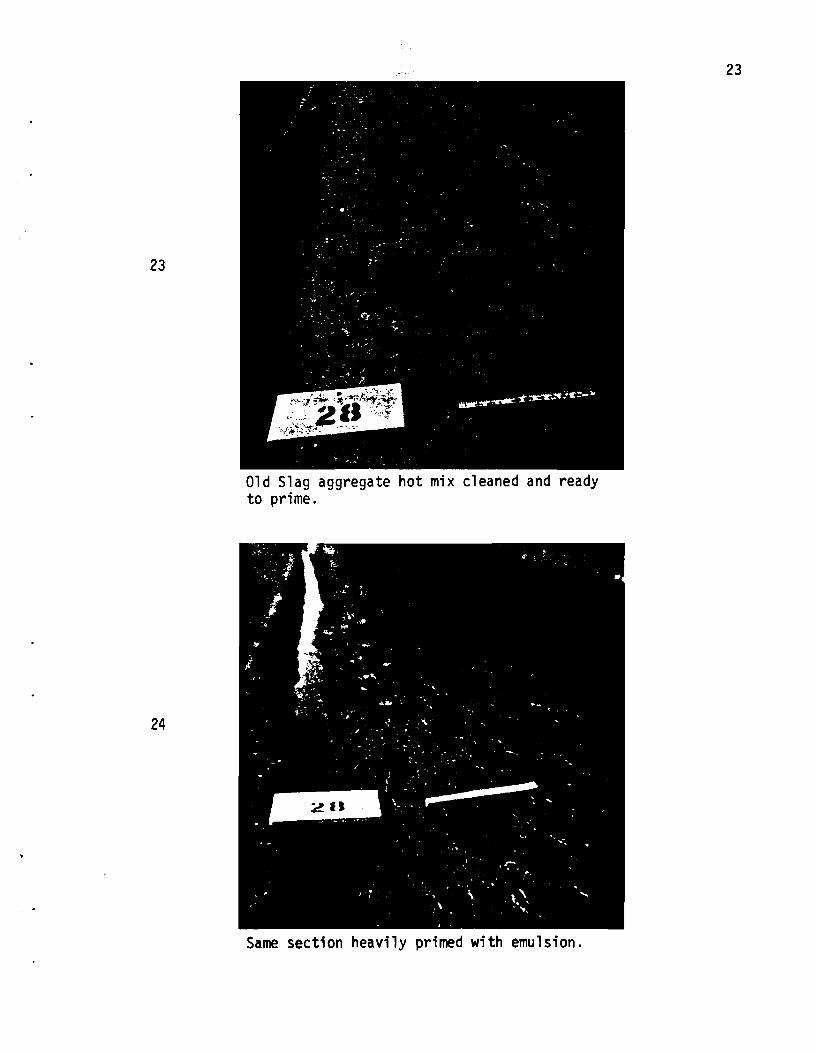
aggregate hot mix. (See Photos 21, 22, and 23). These sections were then heavily
primed with a mixture of one part emulsion EA-llM and two parts water, applied
at a rate of .15 to .25 gallons per square yard, depending on the severity of
the cracks. (See photo 24). Item 292, "Asphalt Stabilized Base" was then blade
laid in these sections to the elevation of the adjacent light-weight hot mix.
(See Photo 25).
Other areas Which were severly cracked but still stable, predominately in
the travel lanes, were primed with a mixture of one part EA-llM emulsion and two
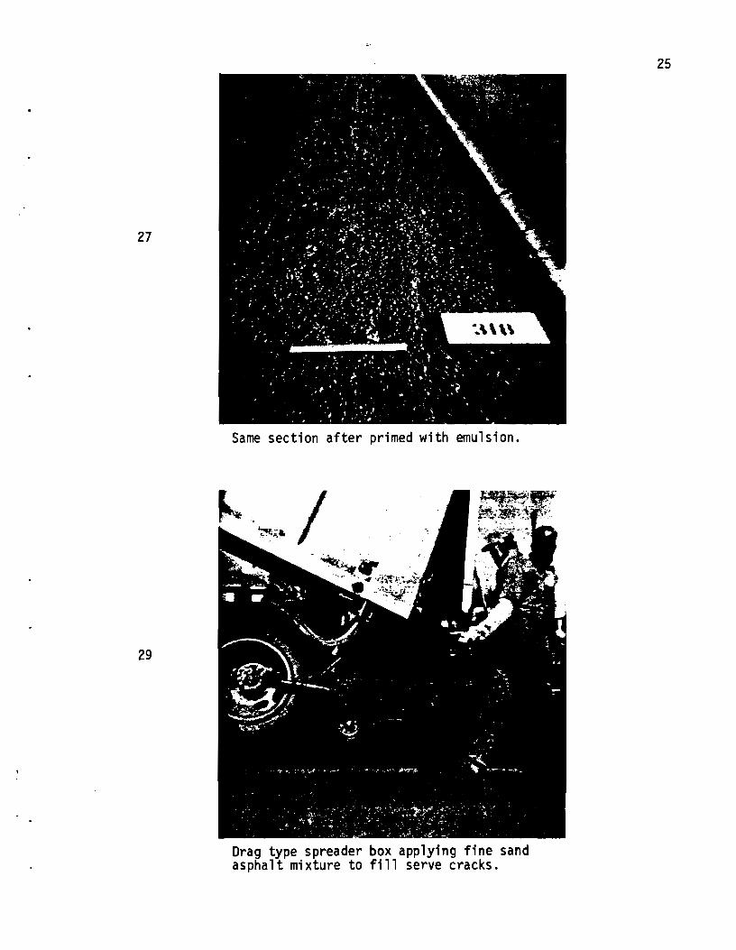
parts of water to serve as a crack seal. (See Photos 26 and 27). In the areas
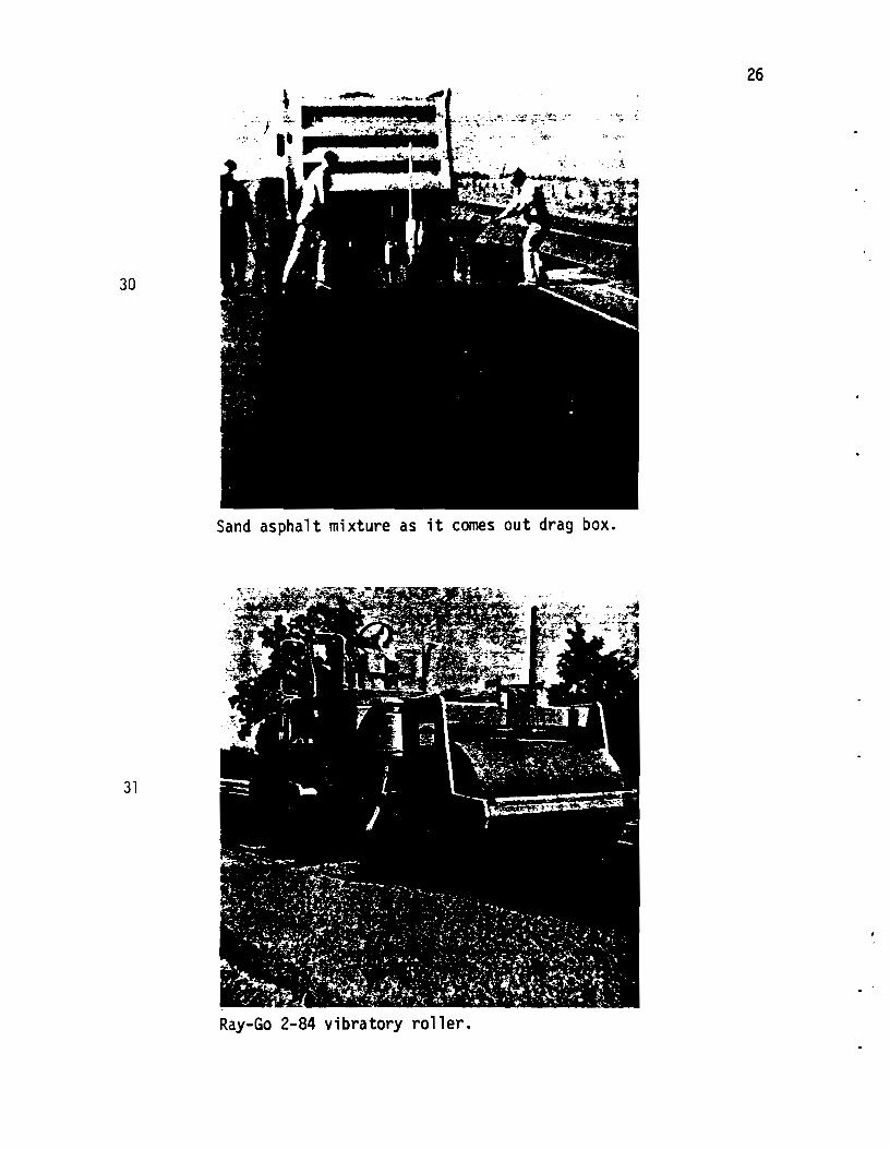
where the cracks were too wide to consider breaching with asphalt-rubber seal,
a mixture of 20% field sand, 80% concrete sand and 7% asphalt was applied by
means of a drag-type spreader box (See photos 29 - 30) and rolled immediately
with a 25-ton pneumatic roller and a Ray-Go 2-84 vibratory roller (See Photo 31)
to force the material into the cracks. The fine mixture aided the thin lift
placement. Traffic was carried on this surface for about two months before the
asphalt-rubber seal coat was applied. The sand asphalt stayed in the cracks
and did not whip out under traffic, but the outlines of the cracks became visible.
All other areas that were not patched or crack sealed, primarily the
shoulders, were primed with a mixture of one part EA-llM and three parts water
at a rate of .10 gallon per square yard.

21
22
Rubber tired front end loader removing old lightweight aggregate hot mix that was no longer bonded to slag aggregate layer.
Exposed slag aggregate hot mix. Not cracked to the extent of the lightweight aggregate hot mix.
22
23
24
Old Slag aggregate hot mix cleaned and ready to prime.
Same section heavily primed with emulsion.
23

24
25
21J
Blade laid hot mix in place.
26
Close up of pavement prior to prime.
27
29
Same section after primed with emulsion.
Drag type spreader box applying fine sand asphalt mixture to fill serve cracks.
25
26
......... , '.: . ..:·•·"l~.::er':';"~--- " .. --:.,.E.·· :, •-.'·'
30
Sand asphalt mixture as it comes out drag box.
31
Ray-Go 2-84 vibratory roller.

27
Spreading: The hot asphalt-rubber mixture was applied as designated by
the Engineer. The rate of application ranged from .50 gallon ?er square yard
to .60 gallon per square yard, with the average rate being .56 gallon per square
yard. (See Photo 33). The length of each shot was limited to that which could
be covered with aggregate by the trucks available without reloading. Joint
paper was used for each new shot. The precoated, preheated, cover aggregate
was applied at an average rate of one cubic yard per 75 square yards.
The 25-ton and 35-ton pneumatic-tired rollers were brought in. The 25-ton
roller worked directly behind the spreader box and rolled while the asphalt
rubber and cover aggregate were both hot. The second roller worked farther
back and rolled at an extremely slow speed so as not to pick up or turn over
the precoated aggregate.
The specification required the contractor to be responsible for the surface
until the work is accepted by the Engineer. After the asphalt-rubber seal coat
had been in place for about four weeks, during the hot weather in May, some
bleeding occurred in the travel lanes. This bleeding was caused by traffic
pressing the Grade 3 aggregate down into the sand-asphalt crack seal which,
although it was not apparent to the eye, had depressed in the wheel paths enough
to cause extra thickness of sand-asphalt. An actual flushing occurred, with the
coverstone allowing traffic to contact the asphalt-rubber (See Photos 34 and 35).
Even though it looked bad, it did not pick up under traffic as a regular bleeding
asphalt would do. To remedy the problem, the contract placed sand on the
bleeding areas, using a spreader box. The sand blotted the asphalt; and the
problem was much less severe than would have occurred if regular AC-5 asphalt
had been used.
Measurement: As stated previously, Special Specification Item 3046,
"Hot Asphalt-Rubber Seal Coat", was patterned after Standard Specification
Item 316 "Seal Coat" which establishes measurement to be by the gallon determined
by strapping a calibrated distributor. This method of measurement presented

33
34
Cut out section shows thickness of asphaltrubber seal coat.
Flushing of asphalt rubber seal coat in wheel paths of main lanes.
28

29
problems; the large 4.500 gallon distributors had never been calibrated by
volume. The screw-type agitator in the bottom of the tank probibited a gauging
stick from being placed vertically into the tank. The mixture also had a foam
on top which gave an erroneous reading. All of this was further complicated by
the fact that the mixture defies gravity and. evidently by capillary attraction,
climbed the gauging stick.
It was decided to use the on-board electronic fifth-wheel scales which
were determined to be accurate to weigh the mixture applied to the road. In
order to convert weight to volume for pay purposes, the unit weight of the
asphalt, rubber. and kerosene mixture had to be determined. Each distributor
load was sampled, using a calibrated container, and the weight per gallon of
that particular load was determ~ and paid for accordingly (See Photos36 anc
37). Since the mixture was composed of a recycled, ground, rubber material, and
probably for other reasons, the weight per gallon of the mixture varied from
7.68 pounds per gallon to 8.05 pounds per gallon, with an average weight of 7.8
pounds per gallon based on 52 tests.
Payment: The hot asphalt-rubber and aggregate in place for this contract
cost $.066 per square yard. At the contract prices bid for this project, the
asphalt-rubber-aggregate layer cost the equivalent of 1-1/8" of asphalt stabilized
base.
Additional Construction Items: Upon completion of the Hot Asphalt-Rubber
seal coat, an asphalt stabilized base course, using 60% minus 3/8" gravel, 20/',
concrete sand, and 20% field sand, stabilized with 5% AC-20 asphalt, was applied
in two courses for a total of 220 pounds per square yard or 2~11 approximate depth.
The construction of the subject project required three different sections:
(1) Asphalt-rubber placed directly on the old lightweight hot-mix.
(2) Lightweight hot-mix was removed, replaced by new black base, and then sealed with asphalt-rubber.

35
36
Traffic pressed seal coat aggregate into sand asphalt mix with flushing resulting.
Collecting sample of asphalt rubber mixture from distributor.
30

37
Calibrated bucket used to determine weight per gallon of each distributor load of asphalt rubber mixture.
31

(3) On the shoulder area, lightweight bot-mix was in place but at a lesser thickness due to variations in cross-slopes.
Cores were taken of the three types of sections. In the cores, the asphalt-
rubber layer is visible, about 3/811 thick, working as a flexible, inner
membrane. Its resilience is designed to relieve internal stresses. Up to
32
this time, the asphalt-rubber layer bas prevented the cracks in the old pave-
ment from reappearing in the new surface (See Photos 1, 2, 3, and 4).
Before and after Photos 38-39, 40-41, 42-43, and 44-45.

38
39
Heavily primed existing pavement prior to applying sand asphalt mix.
Same section as Photo 38, with asphalt rubber seal coat in place. Note cracks showing through sand asphalt mixture.
33

42
Before
43
After
34
212
. . '

35
44
Before
45
After

36
40
47t;
Before
41
After

CHAPTER 4
CONCLUSIONS
37
1. A mixture of hot asphalt and rubber can be applied without undue difficulty.
2. The asphalt-rubber mixture works as a stress-absorbing inner layer and
retards reflective cracking. How long the cracking will be retarded is
still to be determined.
3. The mix serves extremely well under direct traffic. The test section has
been carrying direct traffic for 2~ years and is in excellent condition,
showing no crack reflection.
4. Surface water appears to be adequately sealed from the base.
5. Obviously, there is a limit to crack width. The frequency of cracks does
not appear to affect the results.
6, A hot asphalt-rubber seal appears superior to the normal asphalt seal as a
direct traffic surface course,
7. The six, twelve, and eighteen month pavement evaluations of the 20 test
sections indicate a long term service life for this material,
8. Recommended changes to Special Specification Item 3046.000 (9-76), based
on experience gained fran this project, are:
(1) Measurement: Measure and pay by the ton of completed mix.
(2) Equipment: Specify that the distributor be equipped with on-board
scales, or have platform scales on the job,
(3) Mixing: The amount of kerosene can vary from 2 to 7-~%.
(4) Procedures: Paper must be used at the beginning of each shot.

DEMONSTRATION PROJECT 1-170-77-529
EVALUATION OF RUBBER·ASPHALT MIXTURE USED AS A STRESS RELIEVING INTERLAYER
SIX MONTH PAVEMENT EVALUATION
1. PROJECT STATUS
38
Subsequent to the completion of placement of the hot rubber-asphalt seal six months ago, two courses of asphalt stabilized base (black base) have been placed. Completed depth of black base is approximately two inches. An effort to begin the final surface seal coat was made in the fall, 1977, but the weather was too cool and the aggregate would not stay in the asphalt. The project is now dormant and will remain so until mid May, or when weather conditions and surface temperatures are satisfactory for seal coat operations. Traffic is using the black base surfacing.
2. WEATHER
The placement of the seal began in the spring, 1977, and continued into the summer. Placement occurred in cool weather and in very hot weather, Since completion and overlay with approximately two inches of black base, conditions have varied from temperatures approaching 100°F to 20°F. Extreme dry periods persisted for several weeks in August and in January there was approximately seven days of continuous below freezing temperatures.
3. EVALUATION
Inspection of the twenty test sections indicates a longitudinal crack reflecting through at No, 54 and a small transverse crack at No. 530. There is evidence of minor surface stripping of the black base at numerous locations. Some loads of mix show more than others,
In addition to the test sections there are a few other cracks reflecting through. These are generally in areas where the pavement cracking below was most severe. Some cracking is longitudinal and some transverse. A record of the location of these cracks will be made for reference on future evaluation inspections.
The 0.25 mile section on which traffic is for travelway is in very good condition. There are several cracks in this section, to take on water.
using the hot rubber-asphalt seal (No black base overlay was placed,) but only one definitely wide enough
The overall evaluation after six months is that the stress relieving interlayer is performing well. Considering the extent of existing pavement cracks and the temperature extremes, only a few cracks are surfacing to date.
DEMONSTRAXION PROJECT 1·170·77·529
EVALUATION OF RUBBER-ASPHALT MIXTURE USED AS A STRESS RELIEVING INTERLAYER
TWELVE MONTH PAVE!£NI' EVALUATION
1. PROJECT STATUS
The project was completed and accepted May 26, 1978. The last operations involved placement of a one course surface treatment using Grade 3 Precoated Aggregate and AC Asphalt, and final edge slope grading.
2. WEATHER
Since January weather conditions have been generally dry. Very little rain has occurred since February and current conditions are hot and dry. Numerous days in June have reached 100°F (air). Checks during the project construction indicate that the pavement surface will reach 150° F plus during mid afternoon.
3. EVALUATION
Inspection of the twenty test sections (7·6-78) reveal no cracking reflecting through the new surface. This is to be expected because of the age of the surface and the extreme hot temperatures. The surface is beginning to darken in the wheel paths and show signs of flushing, although to date no maintenance has been required to control bleeding. It is anticipated that some maintenance work will be required in the near future unless the hot weather breaks.
The 0.3 mile section, rural, which has the hot rubber-asphalt seal exposed and was not overlaid, is in excellent shape. The surface shows no cracks and no signs of flushing. (The same can be said for the surface in the curb and gutter section on the SH 36 business route, which is not officially a part of this study.)
At this point all indications are that the stress relieving interlayer is performing very well. The next, and last, evaluation under this study will be made in January, 1979. At that time the surfacing will have aged and colder weather will have occurred, which will allow us to evaluate the reflection cracking, if any.
39
DEMONSTRATION PROJECT 1-170-77-529
EVALUATION OF RUBBER ASPHALT MIXTURE USED AS A STRESS RELIEVING INTERLAYER
EIGHTEEN MONTH PAVEMENT EVALUATION
1. PROJECT STATUS
This is the last stage of Task B of the project plan. The project was completed May 26, 1978, but the hot rubber-asphalt seal (stress relieving interlayer) was completed in July, 1977. Traffic has used the facility continuously.
2. ~ATimR
Since the stress relieving interlayer was placed there have been two summer and two winter cycles of weather. Temperatures have varied from in excess of 100°F to approximately 15°F low. Several days of freezing rain occurred each winter.
3. EVALUATION
40
Inspection on 1-23-79 revealed an excellent pavement condition. There are no cracks visible from a slow moving vehicle and occasional spot checks by foot. Residencypersonnel are making a detailed crack survey and have found a few longitudinal cracks. This data will be included in the Research Report.
My conclusion is that the design for this section is performing as intended. An old pavement with three layers of different type asphaltic concrete (CMACP, slagg agg. HMAC, and Lt. Wt. HMAC) severely cracked in four wheel paths has been sealed, overlayed and surfaced with a high polish value surface course. MOre serv~e time will be required to evaluate the importance of the stress relieving interlayer. It does appear to be serving two functions; 1) as a surface crack deterrent and 2) as a moisture barrier.

SUMMARY
This study demonstrated that ground, reclaimed rubber can be mixed
with asphalt and applied to the road hot, as a seal coat, without a great
deal of difficulty when using the proper equipment and normal construction
techniques.
41
During the eighteen months since placement, the six-month evaluations
have revealed that the rubber-asphalt mixture is functioning as intended,
providing a stress-absorbing inner layer that prevents or retards reflective
cracking and serving as a barrier to surface moisture.
The sections where the asphalt stabilized base was omitted and the
rubber~asphalt seal is carrying direct traffic appear to be serving
exceptionally well, indicating that the rubber-asphalt seal could be used
as a riding surface. The seal could be made of a polish-resistant aggregate
which would be a resilient surface moisture barrier.
ATTACHMENT No. 1
ATTACHMENT No. 2
ATTACHMENT No. 3
ATTACHMENT No. 4
ATTACHMENT No. 5
42
APPENDIX
Special Specification 3046.000 (9-76) -- Hot AsphaltRubber Seal Coat
Standard Item 300, par. 300.2(2), Asphalt Cement
Standard Item 300, par. 300.2(7), Emulsions
Standard Item 304, par. 304.4 - Grades of Aggregate
Standard Item 213, par. 213.2 - Rolling Equipment
ATTACm£N'l' 1 43
Project F 358(&) b c 186-5-24
SPECIAL SPECIFICATION
ITEM 3046
HOT ASPHALT-RUBBER SEAL CQ\ T
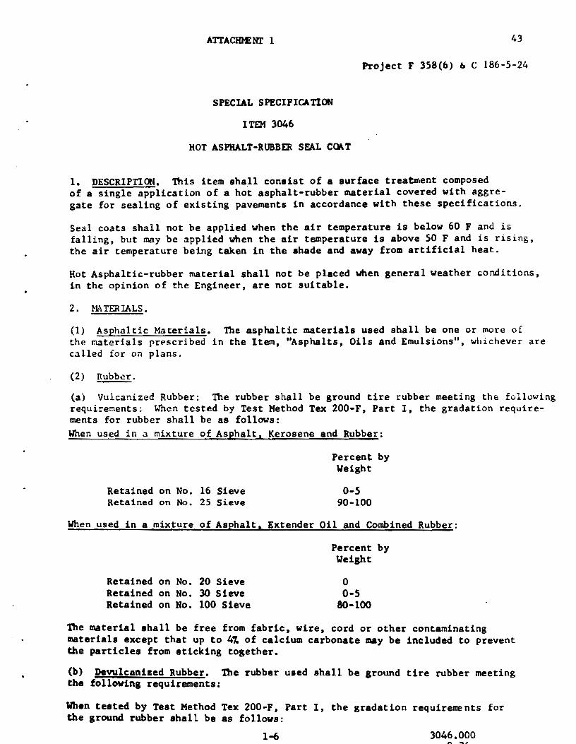
1. DESCRIPTION. This item shall consist of a surface treatment composed of a single application of a hot asphalt-rubber material covered with aggregate for sealing of existing pavements in accordance with these specifications.
Seal coats shall not be applied when the air temperature is below 60 F and is falling, but may be applied when the air temperature is above 50 F and is rising, the air temperature being taken in the shade and away from artificial heat.
Hot Asphaltic-rubber material shall not be placed when general weather conditions, in the opinion of the Engineer, are not suitable.
2. lolA TER IALS.
(1) Asphaltic Materials. 'l1le asphaltic materials used shall be one or more of the r.taterials prPscribed in the Item, "Asphalts, Oils and Emulsions", whichever are called for on plans.
(2) nubbcr.
(a) Vulcanized Rubber: The rubber shall be ground tire rubber meeting the following requi~ements: When tested by Test Method Tex 200•F, Part I, the gradation requirements for rubber shall be as follows: When used in a mixture of Asphalt, Kerosene and Rubber:
Retained on No. 16 Sieve Retained on No. 25 Sieve
Percent by Weight
0-5 90-100
When used in a mixture of Asphalt, Extender Oil and Combined Rubber:
Retained on No. 20 Sieve Retained on No. 30 Sieve Retained on No. 100 Sieve
Percent by Weight
0 0-5
80-100
The material shall be free from fabric, wire, cord or other contaminating materials except that up to 4X of calcium carbonate may be included to prevent the particles from sticking together.
{b) Devulcanized Rubber. The rubber used shall be ground tire rubber meeting the following requirements:
When tested by Teat Method Tex 200-F, Part I, the gradation requirements for the ground rubber shall be as follows:
1-6 3046.000

Retained on No. 10 Sieve Retained on No. 30 Sieve
Percent by Weight
o-5 50-100
The material shall be free from fabric, wire, cord, or other coataminating materials except dusting agents included to prevent the particles from sticking together.
Mill test to determine the state of devulcanization: weight 40-50 grams of rubber and add to a tight 6" rubber mill. The devulcanized rubber will bond on the mill roll in one pass, and will usually be retained on the mill roll.
(3) Kerosene. The kerosene shall have a boiling point of not less than 350° F.
(4) Extender Oil. The extender oil shall be a high-flash, resinous aromatic type which when mixed with the asphaltic material will result in a mixture with an absolute viscosity of the blended materials of approximately 800 poises at 140 F.
Samples shall be submitted and tested prior to use. Sampling and testing shall be in accordance with the methods outlined in AASHTO Designation M226-70.
(5) Aggregate. The aggregate used shall he of the type and grade or types and grades as noted on the plans and selected trom those prescribed in the Items, "Aggregate for Surface Treatments (Class B)", "Aggregate for Surface Treatment (Precoated)(Class B)" or in the Item, "Aggregate for Surface Treatments (Lightweight)11.
3. EQUIPMENT.
44
(1) Distributor. The distributor shall be self-propelled pressure type equipped with a separate power unit, distributing pump capable of pumping the specified materi~l at the specified rate through the distributor tips, and equipment for heating the bituminous material. The distribution bar on the distributor shall be fully circulating with nipples and valves so constructed that they are bathed in the circulating asphalt to the extent that the nipples will not become partially plugged with congealing asphalt upon standing, thereby causing preliminary streaked or irregular distribution of asphalt. Distributor equipment shall include a tachometer, pressure gages, volume measuring devices, and a thermometer for reading temperature of tank contents. The spray bars on the distributor shall be controlled by a boatman riding at the rear of the distributor in such a position that operation of all sprays is in full view and accessible to him for controlling spray widths. The distributor shall be equipped with an agitation system capable of keeping the asphalt and rubber in suspension, preventing settlement of undissolved rubber.
The method and equipment for combining the rubber and asphalt shall be so designed and acceesible that the Engineer can readily determine the percentages, by weight, of each of the two materials being incorporated into the mixture.
(2) Aggregate Spreader. A self-propelled continuous-feed aggregate spreader will be used which will uniformly spread aggregate at the rate specified by the Engineer.
2-6 3046.000 9-76

(3) Rollers. Rolling equipment shall meet the governing specifications for the item, 11Rolling".
45
(4) Broom. Broom shall be a rotary, self-propelled power broom for cleaning existing pavement surfaces.
(S) Aggregate-heating System. The system for heating the cover aggregate shall be of the type that continually agitates the aggregate during heating and in which the temperature can be so controlled that the aggregate will not be injured in the necessary heating operations required to obtain the specified temperature. The burner, or combination of burners, and type of fuel used shall be such that in the process of heating the aggregate to the desired specified temperature, no residue from the fuel shall adhere to the heated aggregate. A continuous recording thermometer shall be provided which will indicate the temperature of the aggregate when it leaves the heating system.
4. CONSTRUCTION METHODS. The Contractor ~y use a mixture of asphalt, kerosene and rubber or of asphalt, extender oil and combined rubber.
(1) Mixture of Asphalt, Kerosene and Rubber.
(a) Mixing.
The asphalt and rubber shall be combincJ as rapidly as possible for such a ti.ml! and at such a temperature that the consistency of the mix approaches that of a semi·fluid material. The temperature of the asphalt shall be between 350 F and and 450 F. At the lower temperature, it will require approximately 30 minutes for the mix to reach the proper consistency after the start of the addition of rubber. At the higher temperature, the reaction will take place within 5 minutes; therefore, the temperature used will depend on the type of application and the methods used by the Contractor. The Engineer shall be the sole judge of when the material has reached application consistency. After reaching the proper consistency, application shall proceed immediately and in no case shall the mixture be held at temperature over 325 F for more than one hour after reaching that point.
The Contractor shall show proof that his equipment is capable of mixing the asphalt and rubber to achieve the required consistency, or demonstrate the ability to achieve this consistency by placing a test section at a location acceptable to the Engineer.
The proportions of the two materials, by weight, shall be 757., plus or minus ~~ asphalt and 257., plus or minus 2%, ground vulcanized rubber. After the mix reaches the proper consistency described in (a) ''Mixing" above, the mix shall be diluted with kerosene. The amount of kerosene used shall be S 1/2'1 to 7 .l/Z7., by v~lume, of the hot asphalt-rubber composition as required for adjusting viscosity for spraying or better "wetting" of the cover aggregate. The kerosene shall have a boiling point of not less than 350 F, and the temperature of the hot mixture shall not exceed this temperature at the time of adding the kerosene.
(b) Prime Coat. Prior to applying the hot asphalt-rubber treatment, the surface to be sealed shall receive a prime coat, applied and paid for as a separate item conforming to the requirements of Item, "Prime Coat 11
•
3-6 3046.000 9-76

(c) Spreadin&• Hot asphalt-rubber mixture shall be applied on the approved prepared surface with specified self-propelled pressure distributor so operated as to distribute the material in the quantity specified, evenly and smoothly, under a pressure necessary for proper distribution.
Hot asphalt-rubber material may be applied in a width not to exceed 13 feet, or as shown on the plans, but may be reduced if uniformity of distributim :a not achieved. No traffic or hauling will be permitted over the freshly-applied hot asphalt-rubber material. Hot asphalt-rubber material shall not be applied until immediate covering with aggregate at the proper temperature is assured.
The cover aggregate shall be preheated to a temperature between 290 F and 350 F. Canvas or similar covers that completely cover each load shall be used to minimize temperature drop of the exposed cover aggregate, if directed by the Engineer.
Aggregate shall be immediately and unifJrmly applied and spread by the specified self-propelled continuous feed aggregate spreader, unless otherwise shown on the plans or authorized by the Engineer in writing. the aggregate shall be applied at the approximate rates indicated on the plans and as directed by the Engineer.
The Contractor shall be responsible for the maintenance of the surface until the work is accepted by the Engineer.
'Ibe entire surface shall be broomed, bladed ~r raked as required by the Engineer and·shall be thoroughly rolled with the type or types of rollers specified on the plans.
46
All storage tanks, piping, retorts, booster tanks and distributors used in storing or handling asphaltic materials shall be kept clean and in good operating condition at all times, and they shall be operated in such manner that there will be no contamination of the asphaltic materials with foreign materials. It shall be the responsibility of the Contractor to provide and maintain in good working order a recording thermometer at the storage heating unit at all times. The Engineer will select the temperature of application based on the temperatureviscosity relationship that will permit application of the asphalt within the limits recotrrnended in the Item, "Asphalts, Oils and Emulsions".
(2) Mixture of Asehalt 3 Extender Oil and Combined Rubber:
(a) Mixing.
The oroportions of the two materials, by weight, shall be 75~, plus or minus ZZ, asphalt and 25~. plus or minus ~ rubber. The asphalt and extender oil shall be combined and heated to a temperature of not less than 400 F. The proportions of the two materials shall be approximately 85~ asphalt and 151. extender oil, by weight, which will result in a blend of materials with an absolute viscosity of approxtmatel) 800 poises at 140 F, when sampled and tested in accordance with AASHTO Designatiot. M226-70.
After the asphalt and extender oil baa reached the proper c~nsistency, the combined rubber shall be added and thoroughly mixed.
4-6 3046.000 9-76

. . . The proportions of the combined rubber, by weight, shall be 607. ground vdlcanized rubber and 407. ground devulcanized rubber, plus or minus 27 ••
47
the Contractor shall show proof that his equipment is capable of mixing the asphalt and rubber to achieve the required consistency, or demonstrate the ability to achieve this consistency by placing a test section at a location acceptable to the Engineer.
(b) Prime Coat. Prior to applying the hot asphalt-rubber treatment, the surface to be scaled shall re~cive a prime coat unless otherwise directed by the Engineer, applied and paid for as a separate item conforming to the Item, "Prime Coat".
(c) Spreading. Hot asphalt-rubber mixture shall be applied at a temperature between 350 F and 450 F on the approved prepared surface with specified selfpropelled pressure distributor so operated as to distribute the material in the quantity specified, evenly and smoothly, under a pressure necessary for proper distribution.
Hut asphalt-rubber rn.'lterial may be applied in a width not to exceed 13 feet, or as shown on the plans, but may be reduced if uniformity of distribution is not achieved. No traffic or hauling will be permitted over the freshly-applied hot asphalt-rubber material. Hot asphalt-rubber material shall not be applied until immediate covering with aggregate at the proper temperature is assured.
Tile cover aggr~gate shall be preheated tv a temperature between 290 F anJ J",U F. Canvas or similar covers that completely cover each load shall be used tu minimize temperature drop of the exposed cover aggregate, if directed by the Engineer.
Aggregate shall be immediately and uniformly applied and spread by the specified self-propelled continuous feed aggregate spreader, unless otherwise shown on the plans or authorized by the Engineer in writing. Tile aggregate shall be applied at the approximate rates indicated on the plans and as directed by the Engineer.
The Contractor shall be responsible for the maintenance of the surface until the work is accepted by the Engineer.
The entire surface shall be broomed, bladed or raked as required by the Engineer and shall be thoroughly rolled with type or types of rollers specified on the plans.
All storage tanks, piping, retorts, booster tanks and distributors used in storing or handling asphaltic materials shall be kept clean and in good operatir~ condition at all times, and they shall be operated in such manner that t}\..ere Will be no contamination of the asphaltic materials with foreign ma·terials. It shall be the responsibility of the Contractor to provide and maintain in good working order a recording thermometer at the storage heating unit at all times. The Engineer will select the temperature of application based on the temperatureviscosity relationship that will permit application of the asphalt within the limits recoDmended in the Item, "Asphalts, Oils, and Emulsions".
S. MEASUREMENT. Hot asphalt-rubber mixture will be measured at point of application on the road in gallons at the applied temperature. The quantity to be paid for shall be the number of gallons used, as directed, in the accepted surface treatment.
s-6 3046.000

·48
Aaaregate will be measured by the cubic yard in vehicles as applied on the road.
Rolling of the type specified on the plana. performed aa r~ired by the Engineer, will be measured by the actual hours auch rolling equipment worka.
6. PAYMENT. 'lbe work performed and matclala fumiahect aa preacribed by this item and measured as provided under "Measur.ant" will be paid for at the uait prices bid for ''Hot Asphalt•R.ubber" and "A&sreaate" of the clua; type and grade specified, which prices shall be f~ll compenaation !or cleaning Che exiating surface; for furnishing all material• an4 freiaht involved; for all heating. mixing, hauling and placing all material• and for all manipulationa, labor, tools, equipment and incidentals, includin& teat sections, necessar.y to complete the work except rolling and prime coat.
All rolling performed as required will be measured and paid for iD accordance with the provisions governing the Item, ''R.olllna".
The prime coat shall be used unless otherwiae directed by the Engineer and will be measured and paid for in accordance with the provisiona governina the Item, "Prime Coat".
6-6 3046.000 9-76

·.
: .
ATTAC'H!£NT NO. 2
300.2
(2t Asphalt Cement. The material shall be homogeneous, shall be free from water, shall not foam when heated to 347 F and shall meet the following requirements:
VISCOSITY GRADE
Test AC-3 AC·S AC·IO AC·20 AC-40
Min. Max Min. Max. Min. Max. Min. Max. Min. Max.
Viscosity. 140 F stokes .... 300;±50 500±100 1000:!200 2000:!400 4000±800
Viscosity, :!75 F •aohs .. . . 1.1 14 1.4 .. 2.5 .:u --
l)eno:tralion, 77 F, I OOg, 5 s~c. ~ ~ ~ . ~10 - 135 - 85 - 55 - 35
Flash Point, C.O.C. F ....... 4.:!5 4.:25 - 450 - 450 -- 1450
Soluh1hty m tru:hlllro.:thylo:nc, po:rco:nt ....... 'JlJ.O - 49.0 - 'JCJ.O - 99,() - ~~~.0
Tests on rcs1ducs frnm th111 ftlrn 0\'\.!ll h:SI.
Vtscoslly. 140 F Slllkl'S .• <JOO -· soc - ~lOOO - ~000 - 12000 Oudthly. 77 F 5 u•" 1'<'1 min, \llh. 100 100 70 50 - 30 ;
Srot h·st ....... Ncg;ll ive for all srades
(3) Latex Additive. A minimum of two percent, by weight, latex
:nhllli\e bolids basisl shall be added to the OA-175 Asphalt or to AC·S Asphall when specified on the plans or m other spedfications in the contract. The latex :.~ddJiive shall be governed by the following specifications:
The lalt>x is to be an anionic emulsion of butadiene-styrene low· temperaturo: copolymer in water, stabilized with fatty-acid soap so as to have good sh>raf:c sl:~bihty, and pnsse!'>sing the followins properties:
Monomer ratio, 8/S ............. . Mmunum solids content .......... . Solid-; ~·on tent per gal. (<~.•6 7% ...... .
Coagulum on 80-mesh scn~·en ...... . Type Anti-oxadant .............. . Moone)' Viscosity of Polymer ( M/L 4 (w:!l2f) ..................... .
pH of Late1t ................... . Surface tension ................. . Brookfield Vis!:osily of Latex ...... .
204
70/30 67% 5.3 lbs. 0.1% max. stain in&
100 min. 9.4- 10.5 2842 dynes/cm2 1200 ps max.. @ 6 7% solids
49

ATTACHMENr NO. 3
300.2
( 7) Emulsions. The material shall be homoaeneous. It shall show no sepuation of asphalt after thorou&h mixin& and shall meet the visc:osity requirements at any time within 30 days after delivery.
ANIONIC iiiUUJONI:
TYPI a., .. Sen•• ...._. S.nU.1 Slow S.thDI
IA·HVRI U·HV-.-~-... ~-~-.. -.t-IV_IIS_ 1~1-A_·_H_V_II_S·-,-,+-I-A ;-I~Os-
Fwrul v,.,,..,.,,,, at 77 1-. "''· furol Vtk'U'IIIJ al I.!! 1-', w~. krwd.- tty Dt~llti.ll&••"· ·; Oal PtJthoa of Dn.hiL.1r. '": Sw\'1' lrt.l. '\ M....:at'tthty tSIMMi•rd lhU
Ccwllna Ctlllt'nl M1111ft1. ·~ P.muhatlaht)' SO~~ of Pti/10 ('aO,:. '1 Dtmwk•t't•hty ·''~..:of NISO (" . .C,:l~. 'N S.IIW~IU, S "•Y•. 't
t~"'"' Tr~• J t·y-:W•I•I
t't'fttiT41•un .11 77 1-, 1001, ~ w..:
........ IOU lOU oJ
1:o
• ! •. 0 I
U I
~u
I i
I friO I
St•lul'l•lil~ '" lr~..hhth.JC'Ib)ltnr. -:.. , •t7 ~
Ow .. IIIII)' .11 , .. t ~, m•m••. •m• _ [u.•J
C A TIO~It EMULSIONS
.......... 100 100 bJ
:o U I
1
....
IOU
'I ot
I I I
.. .. I :Ill
~0
u.l
JU
'u
MU 110 1!0 ltoU "', ~
lUll
., .. ~ 'lUll
...... llaa .
IOU .100 o.•
:.u U.l
10 IIU
U1a. Mn. J Mm. M••
.IU IUU I )U IUU
~u I ou :.u : u ll I U I
P'•biiiJ "·"~"'
:.u
'u .. u ... ~''"'. ! "·~~~~··
i I !U I hill I !U lbiJ
.,., " "'? ~
IlK! IOU -·---
----- 1Yr1--- -------r ..... S.u~...- ~~--~•diU.; s;,;-;-;.- + -- Slo~~~~ _
--- __ -~ ... ~~=-I!_;·CR~_I} IA·CU~ ~A·CIIS:.r~CII!_!_h ....!~CS!.!_~!.A CS~ .. [ .......... I .... .... : .... ..... .... .... t ........ , ..... .. ••
J.,l\ on l muku.lll' I ~:~:::: ~::~:: ~:::::~: !~Jt~~~ IOU J~ IIIUO .'00 100 JOO I IOU 1UU ~O IOO :o IUU
~ua.rm•nt. •' d.l)'- ·; ' 1 J . ' 51'''"~~' \llbthl)' ••"'· t'f I d.av. ~- I • ()rmyl~li-lhl)'. t.: -'" ml 0.1 awr~>••• \\MIIYm I'
d~~·~•YI ""u''"t-..:.:1n•••- ·; •u •u l "•t•nll. •t'tthl) """ ••••r r•"'"'•n.:•
( u•llftl. dry ""'"1•1• I J•ouol
c.·n•l•nl •''" \pUyana '"'' C. ""''"I· ••t "U'• .... I• I f,n
..... ._. ... , l.ur
, n ........ ,,., ,r, .. ,.."• 1 , • .,
'"" I
P'.ttlldf' ~h•rtr '"'I r•"••••• lh"''""· r"~•ll•t' I "'"'''"" ru<rrolfiWC' r•"'''"" \.C'\C' ... ,,. - U.IOI UIU; U.IO' 0\U 0 Jll 010 l· .. m•nt "''"'"' tnl, ',':, I :.u :u
Da.tti .. IMIR
Uti dt~ltl .. lc. by wulunw IJI f'ft'lul:llun, 'l I~ I~ k•,u.h:.• Pf'h.rnl oO ~~~ oS oS ou •U
1~''' ''" ll•,ui~ lr>Jm Pl'llll .. ltOft fc,l t'•Mif.llt&• 1" t". I IIIli. S we. II~U 160 "" 110 120 160 ¥0 110 I I ~0 160 •u 110 Ou,llhty, 7"! f-,' .:rn mrn, .:m . lUll IIlli IOU IIUIJ l'uu 1'::': ' S•llu.,.thl)' IR lrlchlt'f~III)'WM. ~ ! '-'1 ~- "' " "'' I "'' "'"· •-: ~·---~ - ~--! . .'J ·u.:. ___ ~.
"llw 1n1 r•qwni'MRl for wnWnwnllft•Y tM waaud •twa ltw rmYh<f'd •~PIIio~U '' uwd 1n w~' rtwn ~ d.au "•· nr rtw ~niJ· M•r ,..,. N4I1NN tlulllw .. uwnwnl 1u1 bl' rldl frv• 11w runt' ltw wmpW •~ r•~••wd un11111 1a uwd, 11 ttw l'l.apwd lin•" '" W'"
th.11t' d•r• tit h~ ~"-llt l-4ayt stor.., 11atuhly t•\1 "'•Y lw uM"d m"lud vf lhr ~-do~) vllttmrnt ,.,,, ~, tw d•m .. battalll)' .... IIWII 1M made ••llltft )U d•Y• ""''" d•lf' IJI "h&pmc-nl.
207
so
_ ...
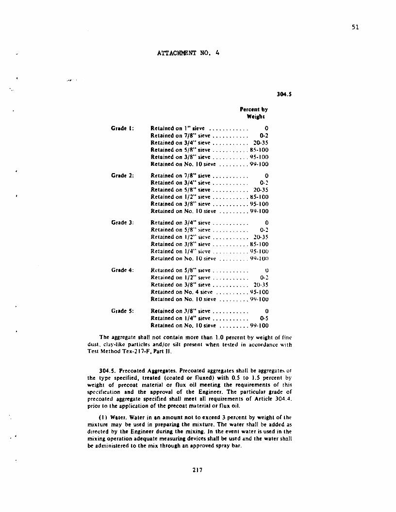
Grade 1:
Grade 2:
Grade 3:
Grade 4:
GradeS:
ATTACHMENT NO. 4
Percent by Weiaht
Retained on I" sieve . . • . . . . . • . . . 0 Retained on 7/8" sieve . . . . . . . . . . . 0-2 Retained on 3/4" sieve . . . . . . . . . . . 20-35 Retained on S/R" sieve ........... 85-100 Retained on 3/8" sieve ........... QS-1 00 Retained on No. l 0 sieve ......... 99- I 00
Retained on 7/8" sieve . . . . . . . . . . . 0 Retained on 3/4" sieve . . . . . . . . . . . 0-.:! Retained on S/8" sieve . . . . . . . . . . . 20-35 Retained on l/2" sieve ........... 85-100 Retained on 3/8" sieve ........... 95-1 00 Retained on No. I 0 sieve ......... 91.)-1 00
Retained on 3/4" sieve . . . . . . . . . . . 0 Retained on 5/8" sieve . . . . . . . . . . . 0-.:! Retained on I /2" sieve . . . . . . . . . . . 20-JS Retained on 3/8" sieve ........... 85-1 00 Retained on I /4" siL'Ve ........... 95-100 Retained on No. I 0 sieve ......... 99-100
Kcta1ned on 5/8" sieve . . . . . . . . . . . 0 Retained on 1/2" sieve . . . . . . . . . . . 0-2 Retained on 3/8" sieve . . . . . . . . . . . 20·35 Retained on No. 4 sieve .......... 9 5-l 00 Retained on No. I 0 sie,·e ......... 9tJ-I 00
Retained on 3/8" sieve . . . . . . . . . . . 0 Retained on 1/4" sieve . . . . . • . . . . . 0-5 Retained on No. I 0 sieve ......... 99-1 00
304.5
The aggregate shall not contain more than 1.0 percent by weight of finc dust. clay-like particles and/or silt present when tested in accordance with Test Method Tex-217-F, Part II.
304.5. Prec:oated Aaareaates. Precoated aggreaates shall be aggregates of the type specified, treated (coated or nuxed) with 0.5 to 1.5 percent by weiaht of precoat material or nux oil meetina the requirements of this specification and the approval of the Engineer. The particular arade of precoated aggreaate specified shall meet all requirements of Article 304.4. prior to the application of the precoat material or nux oil.
(I • Water. Water in an amount not to exceed 3 percent by weight of the mixture may be used in preparina the mixture. The water shall be added as dtrected by the Engineer during the mixing. In the event watl'r is used in the mixing operation adequate measuriDa devices shall be used and the water shall be administered to the mix throuah an approved spray bar.
217
51

ATTACHMENT NO. 5
213.2. Equipment.
(I) The liaht pneumatic tire roller shall consist of not less than nine pneumatic tired wheels, running on ules in such manner that the rear sroup of. tires will cover the entire gap between adjacent tires of the forward aroup, and mounted in a rigid frame and provided with a loadina platform or body suitable for ballast loading. The front axle shall be attached to the frame in such manner that the roller may be turned within a minimum circle. The pneumatic tire roller under workins conditions shall have an effective rolling width of approximately 60 inches and shall be so desisned that by ballast loading, the total load may be varied uniformly from 9,000 pounds or less to 18,000 pounds or more. The roller shall be equipped with tires that will afford ground ~ontact pressures to 4S pounds per square inch or more. The operating load and tire air pressure shall be within the range of the manufacturer's ~hart as directed by the Engineer. The Contractor shall furnish the Engineer with charts or tabulation!i showing the contact ueas and contact pre"urcs for the full range of tire inflation pressures and for the full rang.: of loadings for the partkular tires furnished. The roller under workins conditions shall provide a untform compression under all wheels. The pneumatic tire roller shall be drawn by either a suitable crawler type tractor, a pneumatic tired tractor. or a truck of adequate tractive effort, or may be of the self propelled type, and the roller, when drawn or propelled by either type of equipment, shall be considered a light pneumatic tire roller unit.
(2) The medium pneumatic tire roller (Type A) shall consist of not less than seven pneumatic tired wheels, runnins on u.les in such manner that the rear group of nres will cover the entire gap between adjacent tires of the forward group, and mounted in a risid frame and provided with a loadina platform or bo.1y suitable for ballast loadins. The front axle shall be attached to the frame 1n 'lllch manner that the roller may be turned within a minimum cirde. The pneumatic tire roller under working conditions shall have an effe.:tive rolling width of approximately 84 inches and shall be so designed that by ballast loading the total load may be varied uniformly from 23,500 pounds or less to 50,000 pounds or more. The roller shall be equipped with tires that will aiford ground contact pressures to 80 pounds per square inch or more. The operating load and tire air pressure shall be within the ranae of the manufacturer's chart as directed by the Engineer. The Contractor shall furnish the En~meer with charts and tabulations showin& the contact areas and .:on tact pre~sures for the full range of tire inflation pressures and for the full range of loadings for the particular tires furnished.
fhe pnt:'umo.~tic tire roller shall be drawn by eithc:r a suitable crawler type tr.1.:tor, a pneun1at1c tired tractor, or a tru..:k of adequate tractive effort, or ma~ be of the ~ell-propelled type, and the roller, when drawn or propelled by either type of <'quipmcnt, shall be considered a medium pneumatic tire roller unit. The powt:"r unit shall ha,·e adequate tr:u:tive effort to properly move the operating rolh:r at variable uniform speeds up to approximately S miles per hour.
(3) The medium pneumatic tire roller (Type B) shall conform to the requirements tor Medium Pneumatic Tire Roller, Type A as specified in
75
52