evaluation of preliminary distillation prior to ion ... · evaluation of preliminary distillation...
TRANSCRIPT
Evaluation of Preliminary Distillation Prior to Ion Selective Electrode
Determination of Ammonia in Municipal Wastewater Effluent
By
George Bowman, Royce Kreul, John Melby1, and William C. Sonzogni
Wisconsin State Laboratory of Hygiene University of Wisconsin-Madison
465 Henry Mall Madison, WI 53706
March 13, 1986
Special Note:
The method documented in Appendix C was prepared in 1986 and was appropriate at that time. However, methods and analysis guidance have changed. Please use the approved ion selective electrode methods currently cited in Wisconsin NR219. Please see the following web sites for additional information and guidance in regards to ammonia testing. http://www.dnr.state.wi.us/org/es/science/lc/toolbox/ or
http://www.slh.wisc.edu/ehd/powerpoint/tp_training/tp_training.html
1Wisconsin Department of Natural Resources, 101 S. Webster St., P.O. Box 7921, Madison, WI 53702
- 1 -
- 2 -
The direct ion selective electrode (ISE) technique has been shown to be useful for the analysis of ammonia in wastewater (Thomas and Booth, 1973). The technique is precise, accurate, convenient, and relatively free from interferences. Furthermore, the ISE is inexpensive, requires minimal reagent preparation prior to analysis, and can be used by any laboratory that has a pH meter (mV measuring device). However, federal regulations (40 CFR 136, Guidelines Establishing Test Procedures for the Analysis of Pollutants) prohibit the direct measurement technique unless comparability data are on file to show that preliminary distillation is not required. Unfortunately, many facilities do not have the personnel, equipment, or time to generate comparability data and, therefore, must perform the preliminary distillation step. This requirement poses an economic hardship for many small wastewater treatment plant (WWTP) laboratories with limited staff. Technically, distillation is only required to remove materials that would interfere with the ISE. Volatile amines and mercury are two constituents that most frequently interfere with the ISE. However, since these interferences are rarely encountered in most treated municipal WWTP effluents, it was postulated that distillation is unnecessary. In fact, because of the added step, distillation may decrease reproducibility. Thus, representative effluent samples from Wisconsin were analyzed by the ISE technique with and without distillation to determine the necessity of the distillation step.
STUDY PLAN
Application The comparability study was limited to evaluating samples from municipal WWTPs since: 1) Wisconsin DNR regulatory authority is primarily limited to effluent discharges (WPDES permit program), 2) most small WWTP laboratories do not have the time or staff necessary to perform comparability testing. Waste Selection Regulations (40 CFR 136) specify that comparability data on representative samples be maintained on file with each facility. The Wisconsin DNR Bureau of Wastewater Management determined that the following treatment processes are representative of those used in Wisconsin: 1. Oxidation Ditch 2. Biodisk 3. Biotower 4. Activated Sludge 5. Aerated Lagoon 6. Trickling Filter For each of the treatment processes, effluent samples from three representative facilities were evaluated. The facilities were selected based upon two criteria: 1) facility size (flow), and 2) the amount of industrial waste contributed to the facility. When possible, one waste was selected from a large facility with some industrial contribution, another with mainly domestic waste and a slight industrial contribution, and one with primarily domestic waste. About 4 L of each effluent sample were collected, acidified with sulfuric acid to a pH 2 and promptly shipped to the laboratory. Each sample was analyzed in quadruplicate by the direct ISE technique and the ISE technique after preliminary distillation. The sample selection and analytical scheme for a typical treatment process is illustrated in Figure 1. A total of 144 analyses were performed. Waste Characteristics

- 3 -
The facilities selected for the study are listed in Appendix A. The effluents are characterized by process type, flow, and extent of industrial contribution. The effluents are believed to represent a good cross section of those found in Wisconsin. Methodology The analyses were performed using methods 350.2 and 350.3 from Methods for Chemical Analysis of Water and Wastes (EPA, 19779) and method 417.A from Standard Methods (APHA et al., 1980). Detailed copies of the methods are attached (Appendix B and C). The ISE measurements were made with an Orion model 95-12 ammonia electrode. The mV measurements were made with either an Orion model 701 or Corning model 125 pH/mV meter. Both meters have 1 mV resolution, LED digital displays, and are representative of those used in most WWTP laboratories. The Orion model 701 was used for about 75 percent of the analyses. However, after the meter failed, the Corning model 125 was substituted. ISE Maintenance and Operational Notes The ISE was prepared and maintained according to the manufacturer’s instructions. The ISE was stored in a 10 mg/L ammonia standard (unacidified) when not in use. The slope was checked daily, and the membrane changed when the linearity of the standard curve broke off, generally after about one week. The curve break was characterized by a sluggish response and non-linearity below about 0.5 mg NH3-N/L. If the membrane was changed weekly, the curve was linear to as low as 0.2 mg NH3-N/L, and had a response time of 3-5 minutes at 0.2 mg/L and 60 seconds at 10 mg/L. The Orion technical representative recommends storing the ISE in 1000 mg/L (0.1M) ammonia standard (recommended in the Orion instruction Manual), but this may reduce sensitivity (Smith, 1983). However, we found that the electrode is best stored in a solution with an ammonia concentration near that of the samples being measured. The concentrated storage solution may also “poison” the ISE filling solution, although changing the filling solution daily may prolong the membrane life when more sensitivity is needed (Grant, 1984). ISE Calibration A calibration curve was constructed daily using a minimum of four standards ranging from 0.5-10 mg NH3-N/L. A six point standard curve (standard ranging from 0.2-10 mg NH3-N/L) was checked each time the membrane was replaced. A curve verification standard was analyzed after each 20 samples or at the end of a test run if fewer than 20 analyses were performed. The ISE was always calibrated with undistilled standards. However, a reagent blank and at least one standard were distilled with each group of six distillations. The distilled standard was used to assess distillation efficiency and was always within ± 10% of the expected concentration. Calculations Each standard curve was plotted on two cycle semi-log paper with the concentration on the log axis (X axis) and mV response on the linear axis (Y axis). The curve served as a visual verification of linearity. A Hewlett-Packard Model 97 calculator with a linear regression program was used to verify the curve fit and to calculate the results of the unknowns. A complete description of the regression routine can be found in Appendix C.

- 4 -
RESULTS AND DISCUSSION
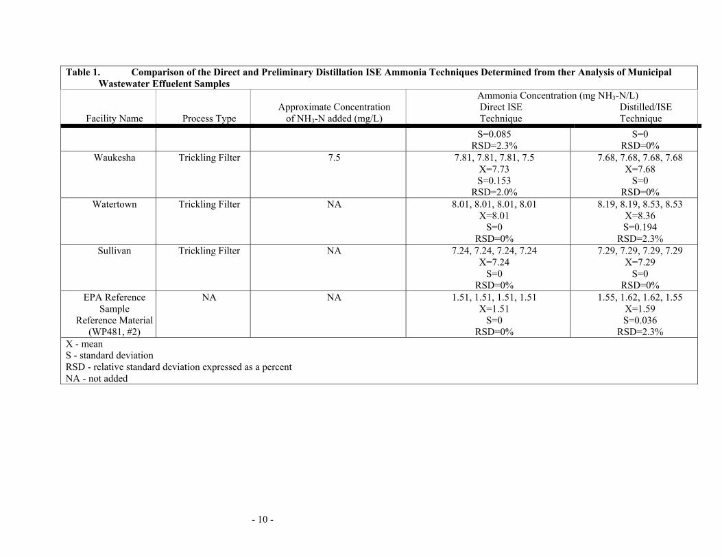
A rough ammonia measurement was made on each effluent sample before the comparability testing was performed. If the ammonia concentrations were below 0.5 mg NH3-N/L, the samples were spiked with ammonia standard (NH4Cl). The samples were spiked for two reasons: 1) to increase the ammonia concentrations to typical discharge permit levels, and 2) to increase the concentration to a measurable level. The majority of WPDES ammonia discharge limits lie between 2-8 mg/L and can range from 1-30 mg/L. It was felt that it was important to perform the comparability testing at or slightly below those typical levels. Furthermore, analytical methods cannot be statistically compared if the concentrations are too low to measure. Also, below 0.5 mg/L the ISE response is quite slow so matrix (interference) effects may not be evident. Method Comparability The data in Table 1 show generally good comparability between the two techniques. The differences observed were random, with no consistent trends noted. The greatest variability was observed in the Madison effluent sample where the means differed by 11.3%. The means of each method were compared using the student’s t-Test (Ryan, et a., 1977). The test shows that the methods were not significantly different at the 95% confidence level (Table 2). The means of each method were also plotted, direct ISE vs. distilled ISE (Figure 2). Linear regression analysis of the data produced a regression coefficient of 0.999 and a slope of 1.00, indicating the techniques directly correspond. Contamination from the laboratory atmosphere has been recognized as a potential source of error in NH3-N analysis (APHA et al., 1980). Although care was taken to minimize contamination when performing this study, some absorption of NH3 could have occurred while processing the samples in the laboratory atmosphere. For example, the sulfuric acid solution used to collect the distillate is an excellent scavanger of NH3. Since the solution is exposed to the laboratory atmosphere during the distillation process, about 30 minutes, it is conceivable that some absorption could occur. This phenomenon could explain some of the variation noted in Table 1. Method Precision The precision of the two techniques was compared using the within sample variance from the replicate measurements determined by both techniques and the F-test. The results in Table 3 show that within sample variances are not significantly different at the 95% confidence level. For all practical purposes, the precision of the methods are comparable. The F-ratio (in the F-test) could be computed for only four sets of samples. The other data could not be used since either one or both of the replicate measurements from the remaining data sets have variances of zero. Since the F-ratio is determined by dividing the variance of one technique by the other, the test is inappropriate if either variance is zero. However, those examined did have comparable precision. Precision comparability is further supported by the relative standard deviation (RSD). The average RSDs in the direct ISE and distilled ISE techniques are 2.45% and 2.46%, respectively. However, it should be noted that of the 19 sets of data compared, 11 of the direct ISE sets have variances of zero while only 6 of the distilled ISE sets have variance of zero. This indicates that the direct ISE technique had slightly better

- 5 -
precision overall. This is not surprising since fewer analytical steps are required in the direct ISE technique. This would naturally reduce the overall imprecision of the tests. It may be possible to improve precision by using a mV meter with 0.1 mV resolution. Such a meter was not used here since it would not represent the type of pH/mV meter found in small WWTP laboratories. Method Accuracy Method accuracy was not assessed in great detail since preliminary distillation was the only issue in question. However, a number of samples were quantitatively spiked and the recovery evaluated. The data, compiled in Table 4, show generally good recovery. The average recovery for the direct technique was slightly high (104%), but not high enough to be a significant consideration. Accuracy was also assessed by analyzing U.S. Environmental Protection Agency reference samples. The results of these analyses (Table 5) show good accuracy from both techniques.
CONCLUSION The study shows the direct ISE measurements of ammonia in treated municipal wastewater effluent are statistically comparable to ISE measurements made in samples that have been subjected to preliminary distillation. Both techniques have similar precision, with the direct ISE technique being slightly better. The direct ISE technique proved to be a convenient, precise, and rapid technique. Analyses could be performed at a rate of about 5 minutes (maximum) per sample, making it much more advantageous than the time consuming distillation technique.
RECOMMENDATIONS It is recommended that Wisconsin wastewater treatment plans exercise the option provided under 40 CFR 136 to eliminate the distillation requirement for the ISE Ammonia analysis. To comply with regulatory requirements, a complete copy of this report should be maintained at each facility utilizing the direct ISE measurement techniques. It is also suggested that the attached methodology (Appendix C, SLH method 220.2) or EPA method 350.3 (EPA, 1979) be used by laboratories utilizing the direct ISE technique. A minimum of three standards, bracketing the concentration range of interest, should be used to construct a standard calibration curve each time ammonia measurements are made. Small laboratories with limited staff could conveniently purchase prepared standards and reagents, thus minimizing analyst time, while still meeting the analytical requirements. Ammonia measurements using the known addition technique described in the Orion Instruction Manual (Orion, 1983) are not recommended at this time. Although this technique obviates the need for a calibration curve, the sample concentration must be known within a factor of three for the technique to be accurate. Further, the preliminary distillation issue was investigated using EPA method 350.3 which requires a calibration curve. On the basis of this study, it cannot be determined whether the known addition technique would work. Therefore, without further study, it is recommended that elimination of the distillation requirement should be only on the condition that the analyses be performed using EPA method 350.3.
ACKNOWLEDGEMENTS
- 6 -
This study was supported by the Wisconsin Department of Natural Resources and the Wisconsin State Laboratory of Hygiene. The following Wisconsin Department of Natural Resources staff provided technical assistance and field support during the study: Ron Arneson, Tom Mugan, Tom Harpt, Jim Kohl, Tom Tewes, Steve Thon, Tom Stibbe, Tom Blake, and Dave Hanson. Bob Schuknecht, JoAnne Wilken, and Chris McSweeney of the State Laboratory of Hygiene provided analytical support and assistance in preparing and reviewing this report. REFERENCES 1. Federal Register. Guidelines Establishing Test Procedures for the Analysis of Pollutants, 40 CFR
Part 136, October. (1984). 2. “Methods for Chemical Analysis of Water and Wastes.” (EPA-600/4-79-020, U.S. Environmental
Protection Agency, Cincinnati, OH. (1979). 3. “Standard Methods for the Examination of Water and Wastewater.” 15th Ed. American Public
Health Association, Washington, D.C. (1980. 4. Smith, D. Personal Communication, Orion Research Technical Representative, Hanover Park, IL.
(1983). 5. Grant, C. Personal Communication, Orion Research Technical Services, Cambridge, MA. (1984). 6. Ryan, T.A., Jr., et al. “MINITAB Student Handbook.” Duxberg Press, North Scituate, MA. (1976). 7. Bauer, E.L., “A Statistical Manual for Chemists.” Academic Press, New York, NY. (1971). 8. Instructional Manual for the Model 95-12 Ammonia Electrode. Orion Research, Cambridge, MA.
(1983). 9. Thomas, R.F. and Booth, R.L., “Selective Electrode Measurement of Ammonia in Water and
Wastes,” Environmental Science and Technology 7(6):523-526 (1973).

- 7 -

- 8 -
Table 1. Comparison of the Direct and Preliminary Distillation ISE Ammonia Techniques Determined from ther Analysis of Municipal Wastewater Effuelent Samples
Facility Name Process Type Approximate Concentration
of NH3-N added (mg/L)
Ammonia Concentration (mg NH3-N/L) Direct ISE Distilled/ISE Technique Technique
Brooklyn Oxidation Ditch 1.8 1.83, 1.83, 1.83 X=1.83
S=0 RSD=0%
2.02, 2.02, 1.87, 1.87 X=1.94 S=0.091
RSD=4.7% Baraboo Oxidation Ditch 4 4.55, 4.55, 4.55, 4.55
X=4.55 S=0
RSD=0%
4.64, 4.64, 4.64, 4.64, X=4.64,
S=0 RSD=0%
Dousman Oxidation Ditch 2.5 2.93, 2.93, 2.93, 2.93 X=2.93
S=0 RSD=0%
2.55, 2.77, 2.77, 2.77, X=2.72 S=0.108
RSD=4.0% Eau Claire Biodisk NA 16.7, 17.4, 17.4, 17.4
X=17.2 S=0.344
RSD=2.0%
17.1, 17.1, 17.1, 17.1, X=17.1,
S=0 RSD=0%
Delafield-Hartland Biodisk 4.5 4.92, 4.72, 4.72, 4.92, X=4.82, S=0.113
RSD=2.3%
4.82, 5.02, 5.02, 5.02, X=4.97 S=0.100
RSD=2.0% Ontario Biodisk NA 2.06, 2.06, 2.06, 2.06
X=2.06 S=0
RSD=0%
2.09, 2.09, 2.09, 2.01, X=2.07 S=0.043
RSD=2.1% Madison Activated Sludge NA 5.31, 5.31, 5.31, 5.31
X=5.31, S=0
RSD=0%
4.64, 4.64, 4.83, 4.83, X=4.74 S=0.109
RSD=2.3%
Stoughton Activated Sludge 1.25 1.55, 1.55, 1.49, 1.49 1.52, 1.46, 1.52, 1.52

- 9 -
Table 1. Comparison of the Direct and Preliminary Distillation ISE Ammonia Techniques Determined from ther Analysis of Municipal Wastewater Effuelent Samples
Facility Name Process Type Approximate Concentration
of NH3-N added (mg/L)
Ammonia Concentration (mg NH3-N/L) Direct ISE Distilled/ISE Technique Technique
X=1.52 S=0.035
RSD=2.3%
X=1.51 S=0.030
RSD=2.0% Milton Activated Sludge NA 12.6, 12.6, 12.6, 12.6
X=12.6 S=0
RSD=0%
11.9, 12.4, 12.4, 12.4 X=12.2 S=0.243
RSD=2.0% Walcomet Biotower 1.2 1.42, 1.42, 1.42, 1.42
X=1.42 S=0
RSD=0%
1.40, 1.40, 1.40, 1.34 X=1.38 S=0.028
RSD=2.0% Clinton Biotower 3.5 3.63, 3.49, 3.49, 3.49
X=3.52 S=0.072
RSD=2.0%
3.56, 3.56, 3.56, 3.56 X=3.56
S=0 RSD=0%
Coleman Biotower NA 20.6, 20.6, 20.6, 20.6 X=20.6
S=0 RSD=0%
20.1, 21.0, 21.0, 21.0 X=20.8 S=0.418
RSD=2.0% Sauk-Prairie Aerated Lagoon NA 1.14, 1.14, 1.10, 1.14
X=1.13 S=0.023
RSD=2.0%
1.43, 1.43, 1.37, 1.43 X=1.42 S=0.028
RSD=2.0% Lomira Aerated Lagoon NA 4.04, 4.04, 4.39, 4.39
X= 4.22 S=0.199
RSD=4.7%
3.95, 3.95, 4.11, 4.11 X=4.03 S=0.092
RSD=2.3%
Ferryville Aerated Lagoon NA 3.56, 3.71, 3.71, 3.56 X=3.63
3.94, 3.94, 3.94, 3.94 X=3.94
- 10 -
Table 1. Comparison of the Direct and Preliminary Distillation ISE Ammonia Techniques Determined from ther Analysis of Municipal Wastewater Effuelent Samples
Facility Name Process Type Approximate Concentration
of NH3-N added (mg/L)
Ammonia Concentration (mg NH3-N/L) Direct ISE Distilled/ISE Technique Technique
S=0.085 RSD=2.3%
S=0 RSD=0%
Waukesha Trickling Filter 7.5 7.81, 7.81, 7.81, 7.5 X=7.73 S=0.153
RSD=2.0%
7.68, 7.68, 7.68, 7.68 X=7.68
S=0 RSD=0%
Watertown Trickling Filter NA 8.01, 8.01, 8.01, 8.01 X=8.01
S=0 RSD=0%
8.19, 8.19, 8.53, 8.53 X=8.36 S=0.194
RSD=2.3% Sullivan Trickling Filter NA 7.24, 7.24, 7.24, 7.24
X=7.24 S=0
RSD=0%
7.29, 7.29, 7.29, 7.29 X=7.29
S=0 RSD=0%
EPA Reference Sample
Reference Material (WP481, #2)
NA NA 1.51, 1.51, 1.51, 1.51 X=1.51
S=0 RSD=0%
1.55, 1.62, 1.62, 1.55 X=1.59 S=0.036
RSD=2.3% X - mean S - standard deviation RSD - relative standard deviation expressed as a percent NA - not added

- 11 -
Regression Coefficient: 0.999 Slope: 1.00 Intercept: -0.016
Figure 2. Comparison of the Direct and Preliminary Distillation ISE Ammonia Techniques
Using Linear Regression Analysis.
0
5
10
15
20
0 5 10 15 20Distilled/ISE
Dire
ct IS
E
Actual Data Points
Calculated regression line

- 12 -
Table 2 Comparability of ISE Ammonia Ananysis Performed on Distilled and Undistilled MunicipaWastewater Samples Using the Paired T-Test1.
Number of Paired Data
sets2
Critical t value
(P=0.05)
Calculated Student's t value Significance
19 2.101 0.10 Not significantly different
1 MINITAB. Ryan et al. (1976). 2 The mean of four replicate analyses of both distilled and undistilled samples are compared TABLE 3. Precision Comparison Determined Using the F-Test1 (Ho: S2u = S2d)
Facility Name
Waste Type
Variance Ratio S2u / S2d F-Ratio
Critical F-Value
(3 d.f. Num.) (3 d.f. Dem.)
Delefield- Hartland
Biodisk 0.0128/0.010 1.28 9.28*
Stoughton Activated Sludge 0.0012/0.0009 1.33 9.28*
Sauk-Prairie Aerated Lagoon 0.0053/0.00078 0.675 9.28* Lomira Aerated Lagoon 0.0396/0.00846 4.68 9.28*
* Precision is not significantly different between the two methods. S2u Variance of four replicate analyses of the undistilled samples S2d Variance of four replicate analyses of the distilled samples d.f. Degrees of freedom 1 Bauer (1971)

- 13 -
Table 4. Accuracy of the Direct and Preliminary Distillation ISE Ammonia Techniques Determined from the Analysis of Samples Spike with Standard Solutions.
Facility ISE
Technique
Background Concentration
(mg/L)
Concentration Added (mg/L)
Observed Concentration
(mg/L) Recovery1
(%) Eau Claire Direct 4.31 5.0 9.39 102 Ontario Direct 2.06 2.0 4.15 104 Sauk City2 Direct 1.13 2.0 3.24 106 Sullivan Direct 3.46 5.0 8.69 104 Average 104
Dousman Distilled 1.36 2.15 3.82 98.3 Eau Claire Distilled 3.42 5.0 7.99 91.4 Average 94.8
1 Recovery = observed-background x 100
spike
2 Mean of four replicated spike samples, X = 104, σ = 0
TABLE 5. Evaluation of the Direct and Distilled ISE Techniques using U.S. Environmental Protection Agency Reference Samples.
Technique
Observed Concentration,
Mean (mg/L)
EPA "True" Concentration
(mg/L)
EPA 95% Confidence Interval
(mg/L)
Distilled ISE (N=4, σ=0.04) 1.59 1.52 1.34-1.70
Direct ISE (N=4, σ=0) 1.51 1.52 1.34-1.70

- 14 -
APPENDIX A
SUMMARY OF COMMUNITY SYSTEMS
Community Type of System
System 1 2
Components
Effluent Limits
(wkly or monthly in mg/l)
bod5 SS NH3
Average2 Design
Flow (mgd)
1984 Total3 Average
Flow
1985 Total4 Average Industrial
Flow (mgd) Industrial
Contributions
Baraboo Oxidation Ditch FM-CM-GR-OD-FC-CL-SA, SP 30 30 No limit 2.160 1.409 0.016 Low
Brooklyn Oxidation Ditch GR-CM-FM-OD-FC-MS-CL, SB 15 20 3/6 0.116 0.056 - Low
Clinton Trickling Filter FM-PC-TF-IC-NT-FF-CL, AN 10 10 5.5 0.305 0.214 - Low
Coleman Bio-Tower FM-GR-CM-FM-FE-FM-PC-BT-AS-FC-CL, AD 30 30 No limit/7 0.275 0.194 - Low
Delafield RBC CM-FM-GR-PC-RBC-FC-FF-CL-PA-SA, AN-SC 10 10 2 2.200 1.156 - Low
Dousman Oxidation Ditch CM-GR-OD-FC-MS-CL 20 20 14 0.350 0.177 - Low
Eau Claire RBC BS-FM-GR-PC-RBC-FC-CL, ST-AN 30 30 No limit 16.300 5.347 0.763 High
Ferryville Aerated Lagoon AL-AL-SL-FM-CL 30 30 No limit 0.035 0.021 - Low
Lomira Aerated Lagoon FM-CM-AL-AL-FF-CL-FM-SA 15 20 3/6 0.491 0.252 0.028 High
Madison Activated Sludge FM-GR-PC-FC-AS-NB-UV, FT-AN-SC-SS 19 20 3/6 50.000 34.533 2.713 Medium
Milton Activated Sludge CM-PC-AS-FC-FM-SL-RI, AN-SC 50 No limit No limit 0.500 - - Low
Ontario RBC BS-PC-RBC-FC-CL, AD-SS 30 30 No limit 0.086 0.036 - Low
Sauk-Prairie Aerated Lagoon FM-AL-AL-SL-RI 50 No limit No limit 1.030 0.523 0.108 High
Stoughton Activated Sludge GR-CM-FM-PC-AS-FC-CL, FT-AN 30 30 No limit 1.650 1.345 0.078 Medium
Sullivan Oxidation Ditch CM-PC-TF-TC-OD-FC-CL, AN 20 20 5/9 0.060 0.045 - Low
Walcomet Bio-Tower GR-PC-BT-IC-NB-FC-FF-CL-PA, AN-SS 10 10 2 3.600 2.273 0.083 Medium
Watertown Trickling Filter CM-GR-PC-FM-TF-IC-TF-FC-CL, AN 20 20 6 5.200 3.719 0.480 High
Waukesha Trickling Filter GR-CM-PC-TF-IC-TF-FC-FF-CL, FT-AN 10 10 2/6 16.000 13.692 0.970 Medium 1 See definition chart on the next page. 2 Data is from DNR design reports. 3 Data is from community self monitoring reports. 4 Data is from NR 101 program
Industrial Contribution Low = 0 to 3% of the 1984 average flow Medium = 4 to 10% of the 1984 average flow High = Greater than 10% of the 1984 average flow
- 15 -
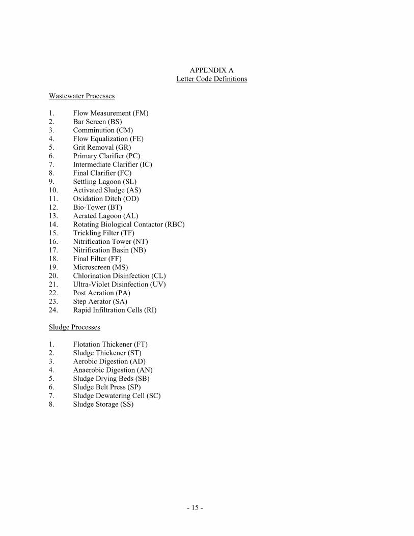
APPENDIX A Letter Code Definitions
Wastewater Processes 1. Flow Measurement (FM) 2. Bar Screen (BS) 3. Comminution (CM) 4. Flow Equalization (FE) 5. Grit Removal (GR) 6. Primary Clarifier (PC) 7. Intermediate Clarifier (IC) 8. Final Clarifier (FC) 9. Settling Lagoon (SL) 10. Activated Sludge (AS) 11. Oxidation Ditch (OD) 12. Bio-Tower (BT) 13. Aerated Lagoon (AL) 14. Rotating Biological Contactor (RBC) 15. Trickling Filter (TF) 16. Nitrification Tower (NT) 17. Nitrification Basin (NB) 18. Final Filter (FF) 19. Microscreen (MS) 20. Chlorination Disinfection (CL) 21. Ultra-Violet Disinfection (UV) 22. Post Aeration (PA) 23. Step Aerator (SA) 24. Rapid Infiltration Cells (RI) Sludge Processes 1. Flotation Thickener (FT) 2. Sludge Thickener (ST) 3. Aerobic Digestion (AD) 4. Anaerobic Digestion (AN) 5. Sludge Drying Beds (SB) 6. Sludge Belt Press (SP) 7. Sludge Dewatering Cell (SC) 8. Sludge Storage (SS)
- 16 -
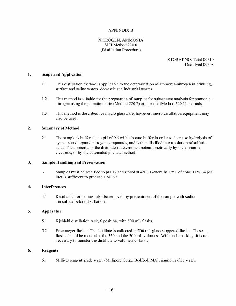
APPENDIX B
NITROGEN, AMMONIA SLH Method 220.0
(Distillation Procedure)
STORET NO. Total 00610 Dissolved 00608
1. Scope and Application
1.1 This distillation method is applicable to the determination of ammonia-nitrogen in drinking, surface and saline waters, domestic and industrial wastes.
1.2 This method is suitable for the preparation of samples for subsequent analysis for ammonia-
nitrogen using the potentiometric (Method 220.2) or phenate (Method 220.1) methods.
1.3 This method is described for macro glassware; however, micro distillation equipment may also be used.
2. Summary of Method
2.1 The sample is buffered at a pH of 9.5 with a borate buffer in order to decrease hydrolysis of cyanates and organic nitrogen compounds, and is then distilled into a solution of sulfuric acid. The ammonia in the distillate is determined potentiometrically by the ammonia electrode, or by the automated phenate method.
3. Sample Handling and Preservation
3.1 Samples must be acidified to pH <2 and stored at 4°C. Generally 1 mL of conc. H2SO4 per liter is sufficient to produce a pH <2.
4. Interferences
4.1 Residual chlorine must also be removed by pretreatment of the sample with sodium thiosulfate before distillation.
5. Apparatus
5.1 Kjeldahl distillation rack, 6 position, with 800 mL flasks.
5.2 Erlenmeyer flasks: The distillate is collected in 500 mL glass-stoppered flasks. These flasks should be marked at the 350 and the 500 mL volumes. With such marking, it is not necessary to transfer the distillate to volumetric flasks.
6. Reagents
6.1 Milli-Q reagent grade water (Millipore Corp., Bedford, MA); ammonia-free water.

- 17 -
6.2 Ammonium chloride, stock solution: 1.0 mL = 1.0 mg NH3-N. Dissolve 3.819 g NH4Cl in about 500 mL of Milli-Q water, add 1 mL conc. H2SO4 and bring to volume in a 1 liter volumetric flask.
6.3 Ammonium chloride, standard solution: 1.0 mL = 0.01 mg. Dilute 10.0 mL of stock
solution (6.2) and 1 mL conc. H2SO4 to 1 liter in a volumetric flask.
6.4 Sulfuric acid solution, 0.4 N: Add 10 mL of concentrated H2SO4 to a 1 L volumetric flask containing about 900 mL of Milli-Q water and mix. After the solution has cooled, dilute to 1 L with Milli-Q water.
6.5 Borate buffer: Add 88 mL of 0.1 N NaOH solution to 500 mL of 0.025 M sodium
tetraborate solution (5.0 g anhydrous Na2B4O7 or 9.5 g Na2B4O7·10H2O per liter) and dilute to 1 liter.
6.6 Sodium hydroxide, 1 N: Dissolve 40 g NaOH in Milli-Q water and dilute to 1 liter.
6.7 Dechlorinating reagent: A dechlorinating reagent may be used to remove residual chlorine
prior to distillation. a. Sodium thiosulfate (1/70 N): Dissolve 3.5 g Na2S2O3·5H2O in Milli-Q water and
dilute to 1 liter. One mL of this solution will remove 1 mg/l of residual chlorine in 500 mL of sample.
7. Procedure
7.1 Preparation of equipment: Add 500 mL of Milli-Q water to an 800 mL Kjeldahl flask. The
addition of boiling chips which have been previously treated with dilute NaOH will prevent bumping. Steam out the distillation apparatus until the distillate shows no trace of ammonia.
7.2 Sample preparation: Remove the residual chlorine in the sample by adding dechlorinating
agent equivalent to the chlorine residual. To 400 mL of sample add 1 N NaOH (6.7), until the pH is 9.5, checking the pH during addition with a pH meter.
7.3 Distillation: Transfer the sample, the pH of which has been adjusted to 9.5 (7.2), to an 800
mL Kjeldahl flask and add 25 mL of the borate buffer (6.5). Distill 300 mL at the rate of 6-10 mL/min. into 50 mL of H2SO4 solution (6.4) contained in a 500 mL Erlenmeyer flask. Dilute the distillate to 500 mL with Milli-Q water and mix thoroughly.
NOTE: The condenser tip or an extension of the condenser tip must extend below the level of the H2SO4 solution.
7.3 Determination of ammonia in distillate: Determine the ammonia content of the distillate
colorimetrically using Method 220.1 or potentiometrically using Method 220.2 (EPA Method 350.3).
8. Calculations
8.1 Spectrophotometric
Mg NH3-N/L = A x B C
- 18 -
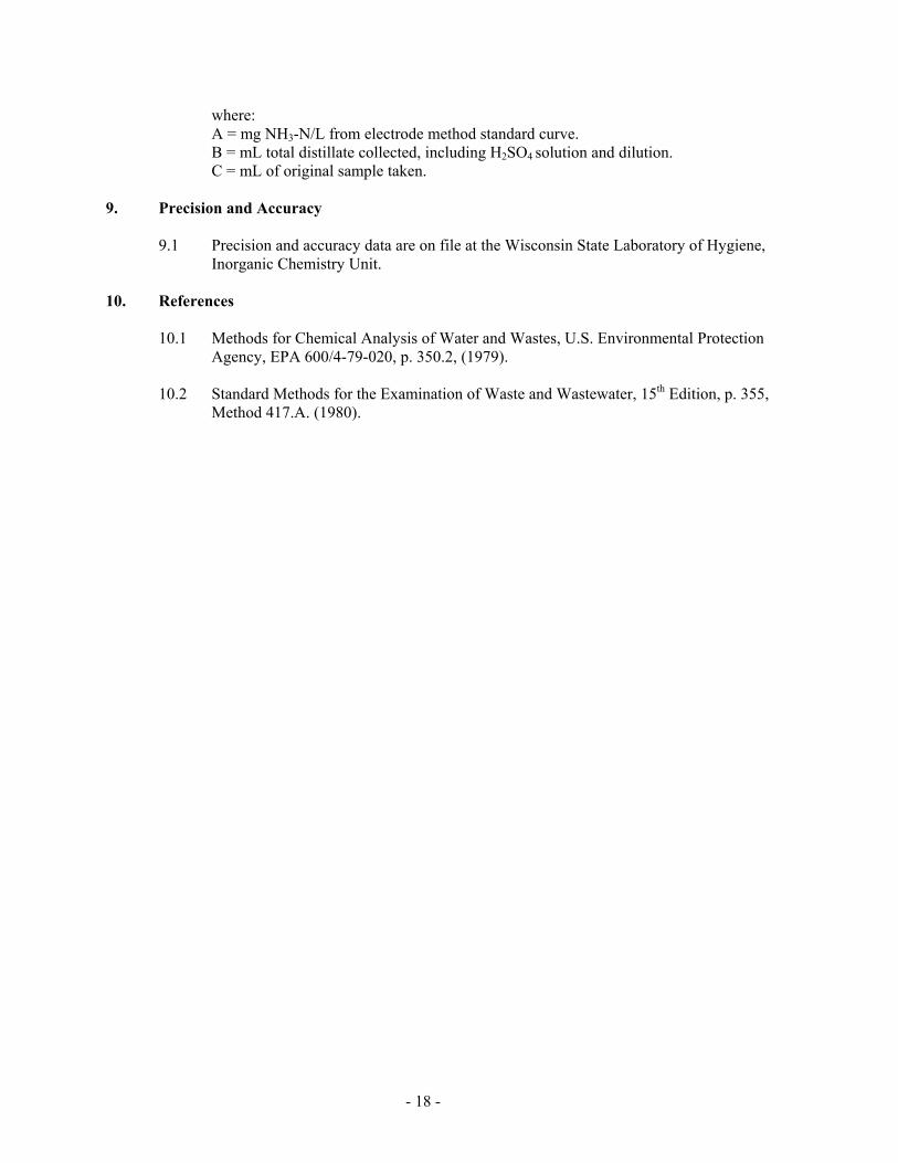
where: A = mg NH3-N/L from electrode method standard curve. B = mL total distillate collected, including H2SO4 solution and dilution. C = mL of original sample taken. 9. Precision and Accuracy
9.1 Precision and accuracy data are on file at the Wisconsin State Laboratory of Hygiene, Inorganic Chemistry Unit.
10. References
10.1 Methods for Chemical Analysis of Water and Wastes, U.S. Environmental Protection Agency, EPA 600/4-79-020, p. 350.2, (1979).
10.2 Standard Methods for the Examination of Waste and Wastewater, 15th Edition, p. 355,
Method 417.A. (1980).

- 19 -
APPENDIX C
NITROGEN, AMMONIA SLH Method 220.2 (Potentiometric, Ion Selective Electrode)
STORET NO. Total 00610
Dissolved 00608
1. Scope and Application
1.1 This method is applicable to the determination of ammonia-nitrogen (NH3-N) in drinking and surface waters, domestic and industrial wastes.
1.2 This method covers the range from 0.03 to 1400 mg NH3-N/L.
2. Summary of Method
2.1 The ammonia is determined potentiometrically using an ion selective ammonia electrode and a pH meter having an expanded millivolt scale or a specific ion meter.
2.2 The ammonia electrode uses a hydrophobic gas-permeable membrane to separate the sample
solution from an ammonium chloride internal solution. Ammonia in the sample diffuses through the membrane and alters the pH of the internal solution, which is sensed by a pH electrode. The constant level of chloride in the internal solution is sensed by a chloride selective ion electrode which acts as the reference electrode.
3. Sample Handling and Preservation
3.1 Preserve samples by acidifying with H2SO4 to a pH <2 and storing at 4°C.
3.2 Generally 1 mL of conc. H2SO4 per liter is sufficient to adjust the pH to <2. 4. Interferences
4.1 Volatile amines act as a positive interference.
4.2 Volatile interferes by forming a strong complex with ammonia. Thus the samples cannot be preserved with mercuric chloride.
5. Apparatus
5.1 pH meter (mV measuring device) with expanded mV scale or a specific ion meter.
5.2 Ammonia selective electrode, such as Orion Model 95-12.
5.3 Magnetic stirrer, thermally insulated, and Teflon-coated stirring bar. Several layers of foam packing material generally provide adequate insulation.
5.4 Micropipet: 1 mL capacity, or adjustable to 1 mL.
6. Reagents
- 20 -
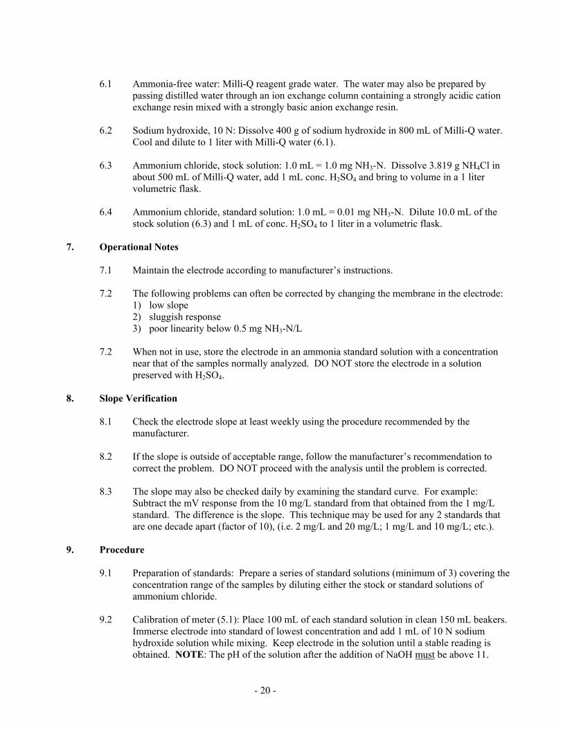
6.1 Ammonia-free water: Milli-Q reagent grade water. The water may also be prepared by
passing distilled water through an ion exchange column containing a strongly acidic cation exchange resin mixed with a strongly basic anion exchange resin.
6.2 Sodium hydroxide, 10 N: Dissolve 400 g of sodium hydroxide in 800 mL of Milli-Q water.
Cool and dilute to 1 liter with Milli-Q water (6.1).
6.3 Ammonium chloride, stock solution: 1.0 mL = 1.0 mg NH3-N. Dissolve 3.819 g NH4Cl in about 500 mL of Milli-Q water, add 1 mL conc. H2SO4 and bring to volume in a 1 liter volumetric flask.
6.4 Ammonium chloride, standard solution: 1.0 mL = 0.01 mg NH3-N. Dilute 10.0 mL of the
stock solution (6.3) and 1 mL of conc. H2SO4 to 1 liter in a volumetric flask. 7. Operational Notes
7.1 Maintain the electrode according to manufacturer’s instructions.
7.2 The following problems can often be corrected by changing the membrane in the electrode: 1) low slope 2) sluggish response 3) poor linearity below 0.5 mg NH3-N/L
7.2 When not in use, store the electrode in an ammonia standard solution with a concentration
near that of the samples normally analyzed. DO NOT store the electrode in a solution preserved with H2SO4.
8. Slope Verification
8.1 Check the electrode slope at least weekly using the procedure recommended by the manufacturer.
8.2 If the slope is outside of acceptable range, follow the manufacturer’s recommendation to
correct the problem. DO NOT proceed with the analysis until the problem is corrected.
8.3 The slope may also be checked daily by examining the standard curve. For example: Subtract the mV response from the 10 mg/L standard from that obtained from the 1 mg/L standard. The difference is the slope. This technique may be used for any 2 standards that are one decade apart (factor of 10), (i.e. 2 mg/L and 20 mg/L; 1 mg/L and 10 mg/L; etc.).
9. Procedure
9.1 Preparation of standards: Prepare a series of standard solutions (minimum of 3) covering the concentration range of the samples by diluting either the stock or standard solutions of ammonium chloride.
9.2 Calibration of meter (5.1): Place 100 mL of each standard solution in clean 150 mL beakers.
Immerse electrode into standard of lowest concentration and add 1 mL of 10 N sodium hydroxide solution while mixing. Keep electrode in the solution until a stable reading is obtained. NOTE: The pH of the solution after the addition of NaOH must be above 11.

- 21 -
Caution: Sodium hydroxide must not be added prior to electrode immersion, since ammonia may be lost from a basic solution.
9.2.1 The electrode response time is concentration dependent. Above 1 mg NH3-N/L,
stable readings should be obtained in about 1 minute. However, below 0.5 mg NH3-N/L, 3-5 minutes may be required.
9.3 Repeat this procedure with the remaining standards, going from lowest to highest
concentration. Using semilogarithmic graph paper, plot the concentration of ammonia in mg NH3-N/L on the log axis vs. the electrode potential developed (mV response) in the standard on the linear axis, starting with the lowest concentration at the bottom of the scale.
9.4 Calibration of a specific ion meter: Follow the directions of the manufacturer for the
operation of the instrument.
9.5 Sample measurement: Place 100 mL of sample in a 150 mL beaker and proceed as in 9.2. Record the stabilized potential (mV response) of each unknown sample.
10. Calculations
10.1 Specific ion meters: Read the ammonia concentration (mg NH3-N/L) directly from the meter.
10.2 mV measuring meter: Obtain the ammonia concentration (mg NH3-N/L) by comparing the
mV response of the unknowns to the standard curve.
10.3 Programmable calculators with linear regression capabilities may also be used. When using a calculator, convert the NH3-N concentration of the standards to their natural log before performing the regression analyzing. Follow the calculator instructions to perform the regression analyzing and to calculate the log concentration of the unknowns. Convert the log concentration to mg NH3-N/L by determining the antilog with the programmable calculator.
11. Precision and Accuracy
11.1 Precision and accuracy data are on file at the Wisconsin State Laboratory of Hygiene, Inorganic Chemistry Unit.
12. References
12.1 Methods for Chemical Analysis of Water and Wastes, U.S. Environmental Protection Agency, EPA-600/4-79-020, p. 350.3 (1979).
12.2 Standard Methods for the Examination of Water and Wastewater, p. 362, Method 417E,
(1980).