evaluation of infill drilling opportunities using ......if the reservoir is incompletely swept,...
TRANSCRIPT

International Journal of Scientific & Engineering Research, Volume 7, Issue 4, April-2016 2005 ISSN 2229-5518
IJSER © 2016 http://www.ijser.org
EVALUATION OF INFILL DRILLING OPPORTUNITIES USING RESERVOIR
CONNECTIVITY ANALYSIS
Azuokwu, A. A1, Yerima, Y2. Ngubi, F. W3, Obeta, P. O4 1, 2, 3, 4. Chemical / Petroleum Engineering Department, Igbinedion University, Okada.
Abstract Infill drilling involves drilling new wells in an existing field within the original well patterns for the purpose of more efficient recovery of petro-leum from the reservoir. If the reservoir is incompletely swept, infill drilling provides an opportunity to increase the rate of production in the field and also to add to reserves. Cases of successful and unsuccessful infill drilling program have been reported. This paper presents the evaluation of infill drilling opportunities using Reservoir Connectivity Analysis (RCA). Two RCA studies that have been carried out in Erha field were used for the study. Erha field is located in OML 133 which is approximately 100 km offshore from Lagos, Nigeria. Results from the first RCA study provide a consistent explanation on the fluid contact distribution across the Erha field. The second RCA study identified both fault juxtaposition and stratigraphic connection windows that were integrated into the connectivity diagram. This is in agreement with the better connectivity and communication across channel complexes indicated by production data. The second RCA fluid predictions for identified compartments generally support the proposed infill drilling opportunities. Opportunities identi-fied on the west flank by detailed sand mapping were supported by the RCA model to contain oil in the identified compartments. However, proposed infill drilling opportunities on the east flank, fall lower in the seriatim due to more isolated gas compartments and com-plex faulting. The second RCA outlined a potential location for an infill drilling opportunity in the east flank channel complex, which should be validated-with 4D integration, although faulting in the east flank continues to be a challenge. Keywords: Infill Drilling, Viability, Reservoir Connectivity, Reservoir compartment, Fault juxtaposition, Stratigraphic .
—————————— ——————————
1.0 INTRODUCTION
NFILL drilling means drilling additional wells, often be-tween the original development wells in order to produce
unrecovered hydrocarbon. Infill drilling involves drilling new wells in an existing field within the original well patterns for the purpose of more efficient recovery of petroleum from the reservoir [1]. According to Frank et al [2], hydrocarbons can re-main un-drained for a number of reasons:
i. Attic / cellar oil may be left behind above (or below) production wells
ii. Oil or gas may be trapped in isolated fault blocks or layers
iii. Oil may be bypassed by water or gas flood iv. Wells may be too far apart to access all reserves.
Generally, Infill drilling can be considered feasible and suc-cessful as long as the amount of production increment covers the cost of the extra wells and associated pipe works at small financial risk. Cases of successful and failures of infill drilling program have been reported [3, 4, 5, 6, 7, and 8]. Studies [9, 10, 11, 12, 13, 14 and 15] have also shown that unless there is continuity between the injecting and production wells during a water flood, the reservoir will be incompletely swept. If the reservoir is incompletely swept, infill drilling provides an op-portunity to increase the rate of production in the field and also to add to reserves [16]. Reviere and Wu [17] further stated
that Infill drilling performance is sensitive to water cut at infill, reservoir heterogeneity and degree of cross flow between lay-ers. Connectivity and compartments represent some of the fun-damental properties of a reservoir that directly affects recov-ery. If a portion of a reservoir is not connected to a well, it can-not be drained [18]. Generally, two connectivity are defined, Geobody or Sandbody connectivity and Reservoir – well con-nectivity or simply reservoir connectivity. Geobody or Sand-body refers to the connectivity of individual elements in the reservoir. Reservoir – well connectivity or reservoir connectivi-ty is the proportion of the reservoir that is connected to the well. Reservoir compartment are non-connected part of the reservoir. Furthermore, some reservoirs are characterized of thin pay thickness particularly in the Niger Delta. When reservoir thickness is less than the height of the trap closure and when faults stratigraphic facies changes provides lateral seals hy-drocarbon contacts in petroleum reservoirs become complex. This makes fluids contacts apparently unpredictable and the development and production of the reservoirs inefficient [19]. Hence in infill drilling program be should designed to cogni-zance of the reservoir connectivity. The Reservoir Connectivity Analysis (RCA) provides a meth-od for combining complex stratigraphic and structural models
I IJSER
International Journal of Scientific & Engineering Research, Volume 7, Issue 4, April-2016 2006 ISSN 2229-5518
IJSER © 2016 http://www.ijser.org
with fluid observation to define reservoir connections and compartments. This paper presents the evaluation of the viability of infill drilling opportunities using reservoir connectivity analysis. Two RCA studies that have been carried out in Erha field were used for the study. 1.1 HISTORY OF ERHA FIELD Erha field is located in OML 133.OML 133 is located approxi-mately 100 km offshore from Lagos (Figure 2.1). It is approxi-mately 1,100 km2 and reflects the 50 percent relinquishment outline of the former OPL (Oil Processing Licence) 209 re-quired as a condition for the February 2006 conversion of the OPL to the OML (Oil Mining Licence) by the Esso Exploration and Production Nigeria Ltd. (EEPNL) and its co-venturers. Water depths range from 800 m to 1960 m [20]. Erha field was discovered with the drilling of the Erha 1 well in February 1999 and was further delineated with the drilling of the Erha 2 well later in 1999 and Erha 3 and Erha 3ST1 wells in 2001. The Erha structure is a NNW-SSE trending, shale-cored anti-cline that plunges towards the NNW. It is developed in the N4 reservoir, which comprises of Middle Miocene confined chan-nel complexes. Twenty three development wells (sixteen pro-ducers - including one redrill and one sidetrack, four gas injec-tors and three water injectors) have been successfully drilled to date. Erha began production on March 27, 2006 from the eastern drill center (DCE). Production from the western drill center (DCW) was brought online on May 17, 2006. Continu-ous injection of both gas and water occurred in June 2006 and has continued since then. Erha field has produced 188 MBO as at the end of 2009, and has 2P (proved and probable) reserves of 492 MBO.
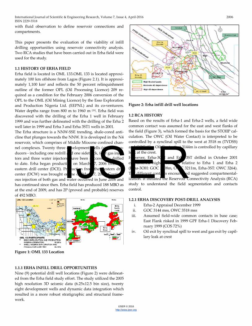
Figure 1: OML 133 Location 1.1.1 ERHA INFILL DRILL OPPORTUNITIES Nine (9) potential drill well locations (Figure 2) were delineat-ed from the Erha field study effort. The study utilized the 2005 high resolution 3D seismic data (6.25x12.5 bin size), twenty eight development wells and dynamic data integration which resulted in a more robust stratigraphic and structural frame-work.
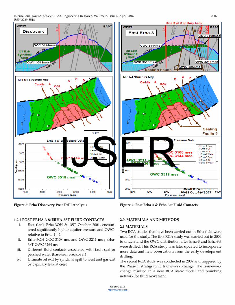
Figure 2: Erha infill drill well locations 1.2 RCA HISTORY Based on the results of Erha-1 and Erha-2 wells, a field wide common contact was assumed for the east and west flanks of the field (Figure 3), which formed the basis for the STOIIP cal-culation. The OWC (Oil Water Contact) is interpreted to be controlled by a synclinal spill to the west at 3518 m (TVDSS) and GOC (Gas Oil Contact) at 3144m is controlled by capillary leak at the crest. However, Erha-3OH and Erha-3ST drilled in October 2001 encountered higher contacts relative to Erha 1 and Erha 2 (Erha-3OH: GOC 3108m, OWC 3211m, Erha-3ST: OWC 3264). The different contacts encountered suggested compartmental-ization. It initiated the Reservoir Connectivity Analysis (RCA) study to understand the field segmentation and contacts control. 1.2.1 ERHA DISCOVERY POST-DRILL ANALYSIS
i. Erha-2 Appraisal December 1999 ii. GOC 3144 mss, OWC 3518 mss
iii. Assumed field-wide common contacts in base case; East Flank risked in 1999 GPF Erha-1 Discovery Feb-ruary 1999 (COS 72%)
iv. Oil exit by synclinal spill to west and gas exit by capil-lary leak at crest
IJSER
International Journal of Scientific & Engineering Research, Volume 7, Issue 4, April-2016 2007 ISSN 2229-5518
IJSER © 2016 http://www.ijser.org
Figure 3: Erha Discovery Post Drill Analysis 1.2.2 POST ERHA-3 & ERHA-3ST FLUID CONTACTS
i. East flank Erha-3OH & -3ST October 2001, encoun-tered significantly higher aquifer pressure and OWCs relative to Erha-1, -2
ii. Erha-3OH GOC 3108 mss and OWC 3211 mss; Erha-3ST OWC 3264 mss
iii. Different fluid contacts associated with fault seal or perched water (base-seal breakover)
iv. Ultimate oil exit by synclinal spill to west and gas exit by capillary leak at crest
Figure 4: Post Erha-3 & Erha-3st Fluid Contacts 2.0. MATERIALS AND METHODS 2.1 MATERIALS Two RCA studies that have been carried out in Erha field were used for the study. The first RCA study was carried out in 2004 to understand the OWC distribution after Erha-3 and Erha-3st were drilled. This RCA study was later updated to incorporate more data and new observations from the early development drilling. The recent RCA study was conducted in 2009 and triggered by the Phase 5 stratigraphic framework change. The framework change resulted in a new RCA static model and plumbing network for fluid movement.
IJSER

International Journal of Scientific & Engineering Research, Volume 7, Issue 4, April-2016 2008 ISSN 2229-5518
IJSER © 2016 http://www.ijser.org
2.2. METHODS The typical RCA workflow is shown in Table 1. TABLE 1: TYPICAL RCA WORKFLOW
Basic Process Process defined
Identify and de-scribe reservoir compartments
Identify potential compartments defined by structure and stratigraphy (map analysis) Establish constraints on fluid contacts in each well. Analyse fluid pressure and composi-tional data and establish pressure lines
Identify and de-fine
Connections be-tween compart-
ments
Identify structural connections between map compartments Identify stratigraphic connections be-tween map compartments
Build an Integrat-ed model
Integrate fluid and map data to establish contacts/contact constraints in penetrated compartments Identify potential system exit pathways – ultimate control on hydrocarbon fill Build a model that explains how fluids exit each compartment to reach a system exit Use this model to predict fluid contact elevations in remaining compartments
Sound stratigraphic and structural frameworks are formidable foundations for RCA study and define the static model. Any change in the framework will lead to modification of the static model. Pressure data and fluid observations are integrated with the RCA static model to identify the potential fluid exit pathways from one compartment to another until the ultimate spill point is reached. The final RCA model is used to predict fluid contact elevations in the remaining un-penetrated com-partments. 3.0 RESULTS AND DISCUSSION 3.1 RCA PRESSURE DATA PLOT There are a few important observations from the excess pres-sure plot (Figure 5).
a) Gas pressure falls on a single pressure line and little offset is observed in the gas column. It implies that gas is in pressure communication for most part of the field.
b) The pressure offset observed in oil column is small; intra-well pressure offset is ~2psi, interwell pressure offset is ~10psi. The pressure communication is often observed across a significant shale interval. At pre-sent, two compartments have been identified in oil column based on the pressure data; west of Sage fault
and east of Sage fault. The pressure separation is ~14psi.
c) The largest pressure offset is observed in aquifer (Figures 5 and 6). The pressure difference is >200psi between the east flank and the west flank. It implies that most compartmentalization occurs in the water leg and the aquifer in the east flank is not in communication with the west flank. The higher water pressure in the east flank suggests that the water is isolated or perched from the rest of the field aquifer.
d) Four Oil and water contacts in the western flank are confirmed either by penetration or by pressure data. The OWC step-down to the west suggests that four water compartments give rise to the different OWCs and the water pressure in each compartment decrease towards the west until reaching the ultimate control point – synclinal spill.
Figure 5: Erha MDT (Modular Dynamics Formation Tester) Excess Pressure (Oil) data
Figure 6: Bosi & Erha—Water Excess Pressure data
IJSER

International Journal of Scientific & Engineering Research, Volume 7, Issue 4, April-2016 2009 ISSN 2229-5518
IJSER © 2016 http://www.ijser.org
3.2 RESULTS FROM THE FIRST RCA Results from the first RCA study are summarized in Figure 7. It provides a consistent explanation on the fluid contact distri-bution across the Erha field.
a) There are three GOCs; 3144m on the western flank, 3112m on the crest, and 3108m on the eastern flank. The existence of three GOCs suggests the oil column is segmented into three compartments. The different oil pressure in each compartment causes the different GOC elevation.
b) Seven OWCs are stepped down from the east to the west until reaching the synclinal spill point in the west, which is interpreted as the ultimate control for oil to exit from Erha. The step-down pattern implies that the aquifer pressure decreases from the east to the west. The different water pressure in each aquifer compartment causes the different OWC elevation.
c) Multiple OWCs do not necessarily mean that the field is segmented. Oil can be in communication.
d) The OWC control point is believed to be a break-over point, which is the up dip point that shale interval is eroded. Higher density fluid (water) spills across the break-over point from a higher pressure compartment to a lower pressured compartment.
Figure 7: Erha Hydrocarbon Distribution Cross-section 3.3 RESULTS FROM THE FIRST RCA (2009 RCA Study: Post-Production) The 2009 RCA study used an integrated approach in develop-ing a static RCA model that explains how fluids moved from identified compartments to the known system exits that is consistent with observed fluid elevations, pressure observa-tions and production data. The major difference between the Phase 5 and Phase 4 frame-works is in the channel stacking pattern. The phase 5 framework is incisonal, whereas the phase 4 is more aggradational (layer cake). This difference suggests that the plumbing system is different.
A set of compartments are delineated based on structure maps. The spill and break-over points are identified for each compartment. Figure 8 shows an example of the compartment identification.
Figure 8: Erha Compartment Identification The 2009 RCA study identified both fault juxtaposition and stratigraphic connection windows that were integrated into the connectivity diagram. This is in agreement with the better connectivity and communication across channel complexes indicated by production data. Stratigraphic connection windows associated with channel incision across channel complexes were identified and incor-porated into the connectivity diagram. These connections across different compartments across channel complexes pro-vide a more robust understanding of reservoir plumbing. Fault juxtaposition connection windows connecting hanging wall and foot wall sections of channel complexes (across same channel or multiple channels) were delineated to address the cross- fault connectivity and identify fault compartments. Fig-ure 9 shows an example of the fault juxtaposition analysis.
Figure 9: Erha Fault Juxtaposition Analyses An integrated static RCA model detailing fluid flow (gas and oil) through identified compartments to the system exits for oil and gas was plotted, using all available well, pressure and production data as control points. Predicted Hydrocarbon distribution maps and charts were developed from the RCA model for each of the nine channel complexes (Figure 10).
IJSER

International Journal of Scientific & Engineering Research, Volume 7, Issue 4, April-2016 2010 ISSN 2229-5518
IJSER © 2016 http://www.ijser.org
Integrated Connectivity Diagram
Figure 10: Erha RCA Connectivity Diagram
The 2009 RCA model shows the Phase 5 reservoir characteriza-tion to be internally consistent. This is based on the agreement of input production data with the phase 5 stratigraphic framework. The RCA model predicted more isolated gas and perched wa-ter compartments than formally known from pressure data analysis.
Figure 11: Predicted RCA HC Fluid Distribution Map (MC3)
Figure 12: Predicted RCA HC Fluid Distribution Map (MC1) Conclusions 2009 RCA fluid predictions for identified compartments gen-erally support the proposed infill drilling opportunities. Op-portunities identified on the west flank by detailed sand map-ping were supported by the RCA model to contain oil in the identified compartments. However, proposed infill drilling opportunities on the east flank, fall lower in the seriatim due to more isolated gas com-partments and complex faulting. 2009 RCA outlined a potential location for an infill drilling opportunity in the east flank (MC1) channel complex, which should be validated with 4D integration, although faulting in the east flank continues to be a challenge.
ACKNOWLEDGMENT The authors wish to thank all individuals and organizations that contributed to the success of this report. Prominent among them are members of Erha field development project.
REFERENCES [1] B.N. Ghosh, S.D Sarkar, J.P Lohiya, and T.K. Das, “Improved Oil
Recovery by Infill Drilling in a mature field”, paper SPE 89368 presented at the2004 SPE / DOC fourteen Symposium on Improved Recovery held in Tulsa Oklahoma, 16-21 April 2004.
[2] J.Frank, C.Mark and M. Graham, “Hydrocarbon Exploration and Production”, Elsevier, 2007.
[3] T.F. McCoy, M.J. Fetkovich, R.B. Needham, and D.E Reese, “Analysis of Kansas Hugoton Infill Drilling Program”. Paper SPE 20779, Jour-nal of Petroleum Technology, June 1992.
[4] E.P. Ofoh, “Geological Heterogeneities in Niger Delta: A case for Additional Recovery through a Combine Effort of Geological Target-ed Infill Drilling, Stimulation and Gas Lift Installation”. Paper SPE 24745 presented at the 67th Annual Technical Conference and Exhibi-tion, Washington DC, October 4-7, 1992.
IJSER

International Journal of Scientific & Engineering Research, Volume 7, Issue 4, April-2016 2011 ISSN 2229-5518
IJSER © 2016 http://www.ijser.org
[5] S.G. Shirzadi, and A.S. Lawal, “Multidisciplinary Approach for Tar-getting New Wells in the Prudhoe Bay Field”. Paper SPE 26093 pre-sented at the Western Regional Meeting held in Anchorage, Alaska, May 26-28, 1993.
[6] B.N. Thai, “Denver Unit Infill Drilling and Pattern Reconfiguration Program”. Paper SPE 599548 Presented at the 2000 SPE Permian Ba-sin Oil and Gas Recovery Conference held in Midland, Texas, March 21-23, 2000.
[7] F.W. Richards, P.J. Vrolijk, J.D, Gordon, and B.R Miller, “Reservoir Connectivity Analysis of a Complex Combination Trap - Terra Nova Field, Jeanne d’Arc Basin, Newfoundland,Canada”. Geological Socie-ty of London 2010.
[8] F.W. Richards, P.J. Vrolijk, J.D Gordon, and B.R. Miller, “Reservoir Connectivity Analysis of a Complex Combination Trap - Terra Nova Field, Jeanne d’Arc Basin, Newfoundland,Canada”. Geological Socie-ty of London 2010.
[9] V.J. Discoll, “Recovery optimization through infill Drilling – Concept, Analysis and Field Results.” Paper SPE 4977 presented at the 1974 SPE Annual meeting, Houston Oct.6.
[10] L.H. Stiles, “Optimizing Waterflood Recovery in a matured Water-flood the Fullerton Clearfor Unit”. Paper SPE 6198 presented at the 51st SPE SPE Annual Technical Conference and Exhibition, New Or-leans, Louisiana, October 3-6, 1976.
[11] C.J. George, and L.H. Stiles, “Improved Techniques for Evaluating Carbonate Waterfloods in West Texas”. Journal of Petroleum Tech-nology, 30, 1547-1554, 1978.
[12] A.H. Barber, C.J.J George, L.H., Stiles, and B.B. Thompson, “Infill Drilling to Increase Reserves - Actual Experience in Nine Fields in Texas, Oklahoma, and Illinois” Paper SPE 11023, JPT, August 1983.
[13] T.L. Gould, and A.M Sam - Sarem, “Infill Drilling for Incremental Recovery” Paper SPE 18941, JPT, March 1989, Page 229- 237.
[14] M.H. Holtz, S.C. Ruppel, and C. Hoccott, “Analysis of Reserve Growth Potential in Leonardian Restricted Platform Carbonate Res-ervoirs, Permian Basin: An Integrated Approach” Paper SPE 22900 presented at the 66th Annual Technical Conference and Exhibition, Dallas, TX, October 6-9, 1991.
[15] L.H. Stiles, and J.B. Magruder, “Reservoir Management in the Means San Andres Unit”. Paper SPE 20751, Journal of Petroleum Technolo-gy, 44, 469-475, 1992.
[16] F.V. Abbots, and A.D. van Kuijk, “Using 3D Geological and Connec-tivity Analysis to locate the remaining Oil Targets in the Brent Reser-voir of the Matured Brent Field” Paper SPE 38473, JPT, August 1997.
[17] R.H. Reviere, and C.H. Wu, "An Economic Evaluation of Waterflood Infill Drilling in Nine Texas Waterflood Units," SPE paper 15037 pre-sented at the Permian Basin Oil & Gas Conference, Midland; March 1986.
[18] K. David-Larue and J. Hovadik, “Connectivity of Channelized Reser-voirs: a Modelling Approach”. Petroleum Geoscience Volume 2, Page 291-308.
[19] P. Vrolijk.: “Application Reservoir Connectivity Analysis- Defining ReservoirnConnections and Plumbing”. Paper SPE- 93577 – MS pre-sented at the 2005 SPE Middle East Oil and Gas Show and Conference held in Kingdom of Bahrain, 12 – 15 March 2005.
[20] T.C. Parker, and A.Sofidiya, “Erha and Erha North Development: Overview”. Paper OTC 18655 presented at the 2007 Offshore Tech-nology Conference held in Houston Texas USA, 30 April – 3 May 2007.
NOMENCLATURE 2P = Proved and Probable COS = Cost DCE = Eastern Drill Center DCW = western Drill Center EEPNL = Esso Exploration and Production Nigeria Limited GOC = Gas Oil Contact GPF = Gross Project Fee HC = Hydrocarbon LC = Lower Channel MBO = Thousand Barrels of oil MC = Middle Channel mss = Metre Subsea OML = Oil Mining License OPL = Oil Processing License OWC = Oil Water Contact RCA = Reservoir Connectivity Analysis STOIIP = Stock Tank Original Initially In Place TVDSS = True vertical Depth Subsea UC = Upper Channel
IJSER