evaluation of dfig placement on small signal stability in multi …iaiest.com/dl/journals/7- iaj of...
TRANSCRIPT
International Academic
Journal of
Science
and
Engineering International Academic Journal of Science and Engineering Vol. 3, No. 3, 2016, pp. 119-132.
ISSN 2454-3896
119
www.iaiest.com
International Academic Institute for Science and Technology
Evaluation of DFIG placement on small signal stability in
multi-machine power systems
Mohammad Pozhhana, Esmael Rok rokb, Jafar soltanic
aMaster Student of power engineering, University of Lorestan, Khorramabad, Iran.
bFaculty of Engineering, University of Lorestan, Khorramabad, Iran
c Faculty of Engineering, University of Lorestan, Khorramabad, Iran
Abstract
Doubly fed induction generator (DFIG) behavior is different from synchronous generators. So, integration
this generators with conventional synchronous generators, can make so many challenges for power
systems. The most important challenge, can be doubly fed induction generator effect on dynamic and
transient stability of power system. In this paper, small signal and transient stability analysis of a two-area
power system is investigated that contains conventional synchronous generators and DFIG. Then the
effect of DFIG placement in different buses is discussed. At first, small signal stability analysis without
power system stabilizer (PSS) is carried, then synchronous generator equipped with PSS. Also, the best
place in order to installation of DFIG in power system is determined and transient stability analysis has
been done on it. To implementation of simulations, MATLAB software is used.
Keywords: synchronous generator, doubly fed induction generator, automatic voltage regulator, power
system stabilizer, small signal stability

International Academic Journal of Science and Engineering,
Vol. 3, No. 3, pp. 119-132.
120
Introduction:
In recent years, the approach of using renewable energy instead of fossil fuels have been considered by
energy suppliers. Among the various renewable resources, wind power is assumed to have the most
favorable technical and economical prospects (S. Heier, 2006). The wind turbine generators (WTGs) are
divided into two basic categories: (i) fixed speed and (ii) variable speed. A fixed-speed WTG generally
uses a squirrel-cage induction generator to convert the mechanical energy from the wind into electrical
energy. DFIG is popular type of variable speed WTGs. Variable speed WTGs can offer increased
efficiency in capturing the energy from wind along with better power quality and with the ability to
regulate the power factor, than fixed-speed WTGs, by consuming or producing reactive power.
In the DFIG, the rotor is connected to power system through the back-to-back converter, while the stator
is connected directly to power system. The control scheme of DFIG decouples the rotational speed of
rotor from the grid frequency (Mullerr S. et al, 2006; Bhinal M. et al, 2014). Because of differences
between DFIG and synchronous generators behavior, integration of these generators can make many
challenges for power system. The most important challenge is dynamic stability of power system.
Dynamic modelling of DFIG for small signal stability presented in [4-8]. Using the proposed model,
eigenvalues analysis is down and their participation factor in order to determine the effect of state
variable on oscillation modes are calculated. The effect of Proportional-Integral (PI) controllers to adjust
the rotor speed reactive power and pitch angle in (Mei Francoise, Pal Bikash, 2005) is investigated. Wind
farms effect in a multi-machine power system on oscillation modes are analyzed (J.J Sanchez Gasca et al,
2004). The influences of increasing the load and length of transmission lines and different penetration
levels of a constant speed wind turbine generator is studied (Thakur D, Mithulanathan, 2009).
In (Gautam Durga et al, 2011), supplementary control strategy is designed for DFIG power convertors to
mitigate the impact of reduced inertia due to significant DFIG penetration in a large power system. Small
signal behavior of DFIG in power factor control mode and voltage control mode were extensively
analyzed (Tsourakis G. et al, 2009). In order to investigating effect of DFIG control strategies, a complete
model is used (Feng We et al, 2006) and the results of eigenvalue and transient stability analysis is shown
that by using proper control strategies, the dynamic and transient stability of power system increased. The
advanced control capabilities of DFIG are used in (Hughes FM et al, 2005) to enhance network damping
via an auxiliary power system stabilizer loop. In (Katrhikeyan Krishnan, Lakshmi ponnusamy, 2014) a
method has been proposed base on GSO algorithm for the coordinated synthesis of power system
stabilizer (PSS) parameters in multi-machine power system. The results shown that the presence of PSS
can effectively enhance the dynamic stability of power system.
The effect of automatic voltage regulator (AVR) and power system stabilizer has been evaluated (Graham
J.W Dadegon, 2007) and shows that the presence of AVR and PSS improve transient and dynamic
stability of power system, respectively. Optimization algorithms can be used to model and optimize the
design of power systems. For example, Jafarian et al., (2016) applied evolutionary algorithm, called
MOPSO, to optimize the parameters of a gas turbine. Other evolutionary algorithms, and their
applications are summarized and utilized in Tavana et al., (2016), Mobin et al., (2017), and Li et al.,
(2016).
International Academic Journal of Science and Engineering,
Vol. 3, No. 3, pp. 119-132.
121
In this paper, the impact of a wind farm connected to power system in terms of small signal and transient
stability been evaluated. At the same environmental conditions, in order to find the best place to install
DFIG, small signal stability analysis has been investigated in different places. The results indicate that the
presence of DFIG causes dynamic instability of power system. In this paper, to improve the dynamic and
transient stability, the use of power system stabilizer is proposed. Eigenvalue and transient analysis
indicate the effectiveness of the proposed method for increasing the stability of power system.
Case study:
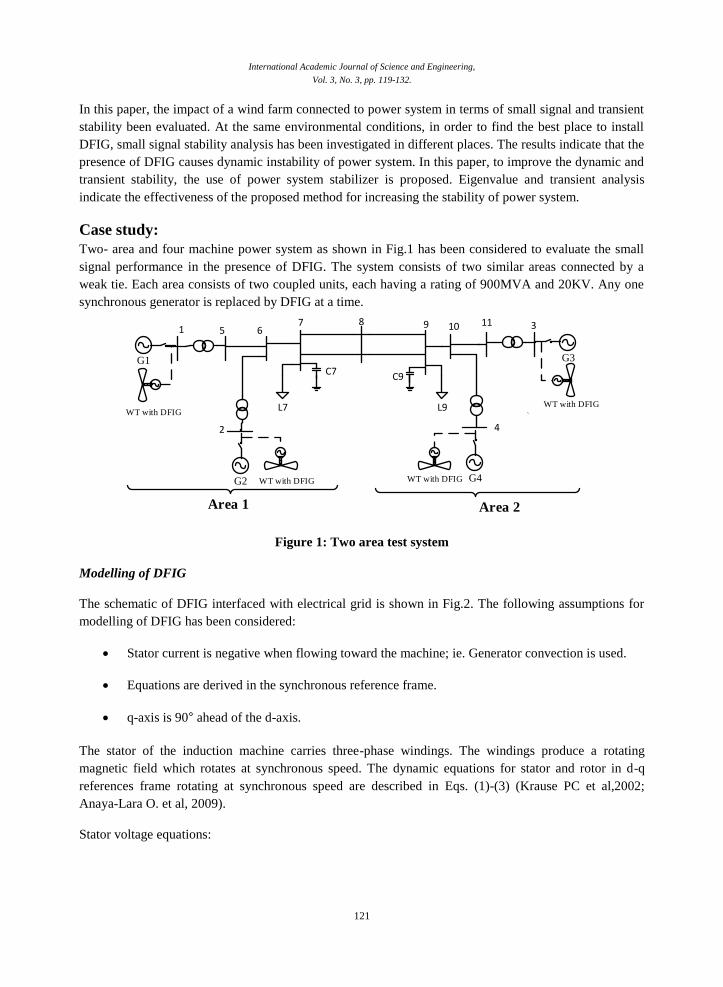
Two- area and four machine power system as shown in Fig.1 has been considered to evaluate the small
signal performance in the presence of DFIG. The system consists of two similar areas connected by a
weak tie. Each area consists of two coupled units, each having a rating of 900MVA and 20KV. Any one
synchronous generator is replaced by DFIG at a time.
G1
`
1 5 67 8 9 10 11 3
42
L7
C7 C9
L9
Area 1 Area 2
WT with DFIG
G2 WT with DFIG G4
G3
WT with DFIG
WT with DFIG
Figure 1: Two area test system
Modelling of DFIG
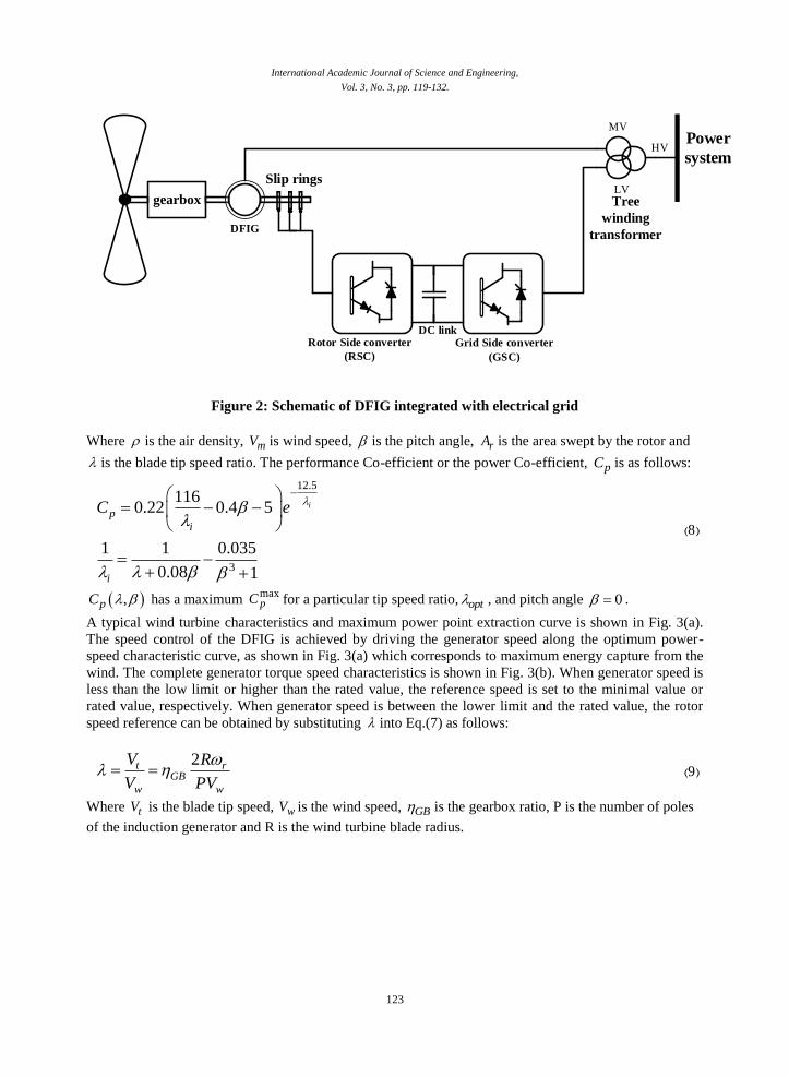
The schematic of DFIG interfaced with electrical grid is shown in Fig.2. The following assumptions for
modelling of DFIG has been considered:
Stator current is negative when flowing toward the machine; ie. Generator convection is used.
Equations are derived in the synchronous reference frame.
q-axis is 90° ahead of the d-axis.
The stator of the induction machine carries three-phase windings. The windings produce a rotating
magnetic field which rotates at synchronous speed. The dynamic equations for stator and rotor in d-q
references frame rotating at synchronous speed are described in Eqs. (1)-(3) (Krause PC et al,2002;
Anaya-Lara O. et al, 2009).
Stator voltage equations:

International Academic Journal of Science and Engineering,
Vol. 3, No. 3, pp. 119-132.
122
(1) 1qsds ds ds
s sqs qs qsbds
V i dR
V i dt
Rotor voltage equations:
(2) 1qrdr dr dr
r sqr qr qrbdr
V i dR S
V i dt
Flux equations in terms of stator and rotor currents:
(3)
ds ss ds m dr
qs ss qs m qr
dr rr dr m ds
qr rr qr m qs
X i X i
X i X i
X i X i
X i X i
Where dsV and qsV are d and q-axis stator voltage, respectively. drV and qrV are d and q-axis rotor
voltage. dsi and qsi are d and q-axis stator current. dri and qri are d and q-axis rotor currents,
respectively.is rotor reactance, rX is stator reactance, sX is rotor resistance, rR stator resistance, is sR
is rotor speed and S is slip. s is magnetization reactance, mX
The expression for the stator and rotor currents as the state variables are obtained by substituting the flux
Eqs.(3) into the stator and rotor voltage Eqs.(1) and (2), respectively.
Wind turbine model for DFIG
In power system studies, wind turbine model is important. The mathematical equation of a one-mass
model is given by Eq.(4):
(4) 1
2
rm e
dT T
dt H
Where H is inertia constant in KWs/KVA, eT and mT respectively are electromagnetic torque and,
mechanical torque as follow:
(5) e m dr qs qr dsT X i i i i
(6) wm
r
PT
Where wP is the mechanical power extracted from the wind and is as follows:
(7) 3( , )2
w p r mP C A V
International Academic Journal of Science and Engineering,
Vol. 3, No. 3, pp. 119-132.
123
gearbox
DFIG
Slip rings
DC linkRotor Side converter
(RSC)
Grid Side converter
(GSC)
MV
LV
HV
Tree
winding
transformer
Power
system
Figure 2: Schematic of DFIG integrated with electrical grid
Where is the air density, mV is wind speed, is the pitch angle, rA is the area swept by the rotor and
is the blade tip speed ratio. The performance Co-efficient or the power Co-efficient, pC is as follows:
(8)
12.5
3
1160.22 0.4 5
1 1 0.035
0.08 1
ip
i
i
C e
,pC has a maximum maxpC for a particular tip speed ratio, opt , and pitch angle 0 .
A typical wind turbine characteristics and maximum power point extraction curve is shown in Fig. 3(a).
The speed control of the DFIG is achieved by driving the generator speed along the optimum power-
speed characteristic curve, as shown in Fig. 3(a) which corresponds to maximum energy capture from the
wind. The complete generator torque speed characteristics is shown in Fig. 3(b). When generator speed is
less than the low limit or higher than the rated value, the reference speed is set to the minimal value or
rated value, respectively. When generator speed is between the lower limit and the rated value, the rotor
speed reference can be obtained by substituting into Eq.(7) as follows:
(9) 2t r
GB
w w
V R
V PV
Where tV is the blade tip speed, wV is the wind speed, GB is the gearbox ratio, P is the number of poles
of the induction generator and R is the wind turbine blade radius.

International Academic Journal of Science and Engineering,
Vol. 3, No. 3, pp. 119-132.
124
Figure 3: Control strategies for DFIG; (a) characteristic for maximum power point tracking, (b) Control strategies for DFIG
Torque and Voltage Control Scheme
The purpose of the torque controller is to modify the electromagnetic torque of the generator according to
wind speed variations and drive the system to the optimal operating point reference. The complete block
diagram of torque control scheme is shown in Fig.4.
The voltage control or power factor control at the terminal of DFIG is achieved through the rotor side
converter. The terminal voltage will increase or decrease with the change in reactive power delivered to
the grid. The voltage controller should fulfil the following requirements in such a situation:
The reactive power consumed by the DFIG should be compensated.
If the terminal voltage is too low or too high compared with the reference value, then dr refi for
d-axis rotor current should be adjusted appropriately.
The complete block diagram of the DFIG terminal voltage controller is shown in Fig.5. All the variables
shown in the block diagram are in per unit (Bhinal Mehta et al, 2015).
Xss
Xmωs|VS|Figure 3b +
-++
Iqr,ref
Iqr
Tsp
S[Idr
|Vs|
ωr Vqr
Kp1+Ki1
S
S
(Xrr- m
Xss
X2
)Idr+Xm
2|Vs|
Xssωr
]
Vqr
,X1
Figure 4: Torque control scheme

International Academic Journal of Science and Engineering,
Vol. 3, No. 3, pp. 119-132.
125
Iqr
Kp3
S
1
Xmωs
++ +-
+-
+-
|Vs|
|Vs|ref X2Idr,ref
Idr
VdrX3
|Vs|
Kp2+Ki2
SVdr
,
SS(Xrr- Xm
2
Xss
)Iqr
Figure 5: Voltage control scheme
Modelling of power system stabilizer
In order to damping oscillations of power system, PSS applying additional signals to the excitation
system or AVR. The deviation rotor speed (Δω), frequency, terminal voltage and oscillating power are the
most common input signal for PSS. The block diagram of power system stabilizer and automatic voltage
regulator is shown in Fig.6. where stabK is the controller gain, wT is a washout time constant (s) and 1T to
4T are lead-lag time constants (s). AVR and PSS parameters for each generator should be selected to
ensure that system performance under a wide range of operating conditions is appropriate.
1
1+sTRKA
1+sTA
1+sTB
KSTAB
+--
sTw
1+sTw
1+sT1
1+sT2
1+sT3
1+sT4
Vref
EfdVt
ωr
Figure 6: Block diagram of AVR and PSS
Small signal stability
The small signal stability and the dynamic performance of power system are related to the damping of the
electromechanical modes of oscillation. This oscillatory behavior is associated fundamentally with (i) the
variation in electrical torque developed by synchronous machines as their rotor angles change, (ii) the
inertia of their rotors. The frequencies associated with these modes of oscillation are typically in the range
from 0.5 to 4 Hz.
Modes of oscillations

International Academic Journal of Science and Engineering,
Vol. 3, No. 3, pp. 119-132.
126
Electromechanical modes of oscillation consist of local area mode and inter-area mode, which having
frequency range of 0.8-2Hz and 0.2-0.8 Hz, respectively. Small signal stability requires that these modes
should be adequately damped. The presence of PSS greatly influence the damping of these modes and can
be assessed by means of eigenvalue analysis. The eigenvalue analysis can be carried out by linearizing the
system about an operating point and representing it in state space form. For stability, all of the
eigenvalues must lie in the left half complex plane. Any eigenvalue in right half plan denotes an unstable
dynamic mode and system instability. The damping contribution provided by any means shifts the location
of the eigenvalues associated with the dominate oscillatory modes to the left half of the plane.
Eigenvalues computation
The behavior of a power system, can be described by the complete set of n-first order non-linear ordinary
differential and algebraic equations. The differential and algebraic of synchronous generators are given in
(P. Kundur et al, 1994).
(10) ( , , )x f x z u
(11) ( , , )o g x z u Where x, z and u are state, algebraic and input variables. f and g are differential and algebraic vectors. In
eigenvalue analysis Eqs.(10) and (11) linearized about an operating point. Finally, the poles of system are
the roots of the characteristic equations given by:
(12) det( ) 0SI A Above equation can be written as characteristic equation:
(13) det( ) 0A I The value of 𝜆 which satisfy the characteristic equations, are known as the eigenvalues of matrix A. the
number of eigenvalues are equal to the number of first-order differential equation. Eigenvalues may be
real or complex as shown:
(14) i i ij
For a given eigenvalue, frequency and damping ratio of oscillation can be calculated by using the
following expressions:
(15) 2
iif
(16) 2 2
ii
i i
Results and discussions
As already mentioned, the power system shown in Fig.1 is used for evaluation of small signal stability. In
order to determine the best location for the replacement of DFIG with signal stability. In order to

International Academic Journal of Science and Engineering,
Vol. 3, No. 3, pp. 119-132.
127
determine the best location for the replacement of DFIG with synchronous generators, eigenvalue
analysis for two following cases was evaluated.
Case 1: The remaining synchronous generators are without power system stabilizer.
Case 2: The remaining synchronous generators are equipped with power system stabilizer.
The result of eigenvalue analysis for case1 is shown in Fig.7 and dominant eigenvalues, frequency and
damping ratio of oscillations are shown in table1.
Table1: Dominant eigenvalues for case 1
Damping ratio
(%)
Frequency of oscillation
(in Hz) Eigenvalue
6.67
3.51
-54.97
100
-100
4.003
1.6
0.75
0
0
-1.704±j25.15
-0.3534±j10.05
3.12±j4.742
-0.0423+0j
5.716+0j Lo
cati
on
of
DF
IG:
Bu
s 1
9.22
2.53
19.43
99.76
-100
-100
-100
4.575
1.35
1.22
0.1
0
0
0
-2.663±j28.75
-0.2154±j8.491
-1.52±j7.673
-9.597±j0.6726
10.66+0j
0.3762+0j
3.254+0j Lo
cati
on
of
DF
IG:
Bu
s 2
13.3
3.53
-45.78
98.87
-100
100
3.7
1.575
0.75
0.122
0
0
-3.128±j23.31
-0.3495±j9.899
2.644±j4.731
-5.171±j0.7703
6.576+0j
-0.09488+0j
Lo
cati
on
of
DF
IG:
Bu
s 3
3.65
4.98
29.21
30.43
-100
-100
1.56
1.146
2.65
0.064
0
0
-0.3579±j9.801
-0.3591±j7.203
-5.092±j16.67
-0.1339±j0.421
4.43+0j
1.442+0j
Lo
cati
on
of
DF
IG:
Bu
s 4
International Academic Journal of Science and Engineering,
Vol. 3, No. 3, pp. 119-132.
128
Figure 7: Plot of eigenvalue for case 1
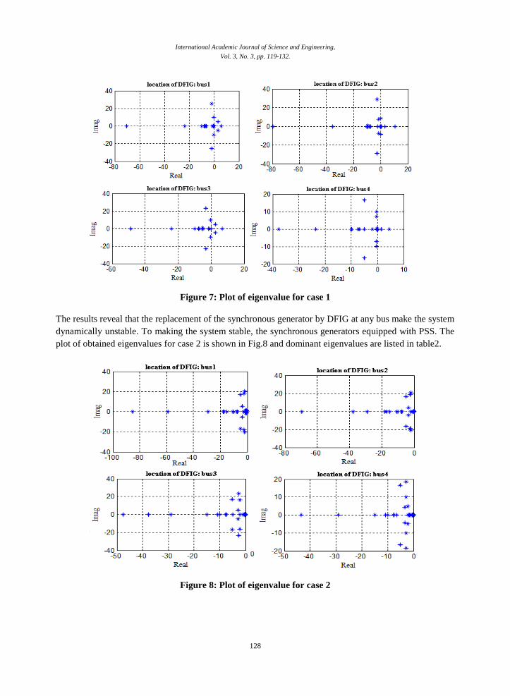
The results reveal that the replacement of the synchronous generator by DFIG at any bus make the system
dynamically unstable. To making the system stable, the synchronous generators equipped with PSS. The
plot of obtained eigenvalues for case 2 is shown in Fig.8 and dominant eigenvalues are listed in table2.
Figure 8: Plot of eigenvalue for case 2
International Academic Journal of Science and Engineering,
Vol. 3, No. 3, pp. 119-132.
129
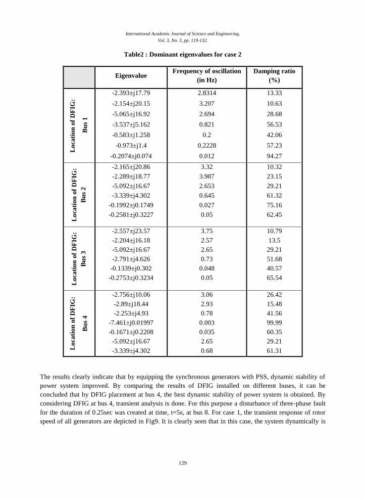
Table2 : Dominant eigenvalues for case 2
Damping ratio
(%)
Frequency of oscillation
(in Hz) Eigenvalue
13.33
10.63
28.68
56.53
42.06
57.23
94.27
2.8314
3.207
2.694
0.821
0.2
0.2228
0.012
-2.393±j17.79
-2.154±j20.15
-5.065±j16.92
-3.537±j5.162
-0.583±j1.258
-0.973±j1.4
-0.2074±j0.074
Lo
cati
on
of
DF
IG:
Bu
s 1
10.32
23.15
29.21
61.32
75.16
62.45
3.32
3.987
2.653
0.645
0.027
0.05
-2.165±j20.86
-2.289±j18.77
-5.092±j16.67
-3.339±j4.302
-0.1992±j0.1749
-0.2581±j0.3227
Lo
cati
on
of
DF
IG:
Bu
s 2
10.79
13.5
29.21
51.68
40.57
65.54
3.75
2.57
2.65
0.73
0.048
0.05
-2.557±j23.57
-2.204±j16.18
-5.092±j16.67
-2.791±j4.626
-0.1339±j0.302
-0.2753±j0.3234
Lo
cati
on
of
DF
IG:
Bu
s 3
26.42
15.48
41.56
99.99
60.35
29.21
61.31
3.06
2.93
0.78
0.003
0.035
2.65
0.68
-2.756±j10.06
-2.89±j18.44
-2.253±j4.93
-7.461±j0.01997
-0.1671±j0.2208
-5.092±j16.67
-3.339±j4.302 Lo
cati
on
of
DF
IG:
Bu
s 4
The results clearly indicate that by equipping the synchronous generators with PSS, dynamic stability of
power system improved. By comparing the results of DFIG installed on different buses, it can be
concluded that by DFIG placement at bus 4, the best dynamic stability of power system is obtained. By
considering DFIG at bus 4, transient analysis is done. For this purpose a disturbance of three-phase fault
for the duration of 0.25sec was created at time, t=5s, at bus 8. For case 1, the transient response of rotor
speed of all generators are depicted in Fig9. It is clearly seen that in this case, the system dynamically is

International Academic Journal of Science and Engineering,
Vol. 3, No. 3, pp. 119-132.
130
unstable. For case 2, the transient responses of rotor speed and angle of generators are shown in Figs 10
and 11, respectively.
The results of transient analysis are consistent with the results of eigenvalue analysis and reveal that the
PSS play a vital role to improve the dynamic and transient stability of power systems.
Figure 9: Transient responses for rotor speed of all generator for case1
Figure 10: transient response for rotor speed of all generator for case2

International Academic Journal of Science and Engineering,
Vol. 3, No. 3, pp. 119-132.
131
Figure 11: Transient response for rotor angle of generators for case 2
Conclusion:
Since the behavior of DFIG is different from conventional synchronous generator, So integration wind
turbines based-DFIG, affect the dynamic and transient stability of power system. In this paper, a
comprehensive assessment of DFIG in power system is provided. Furthermore, impact of DFIG
placement is investigated. The result reveal that the replacement of the synchronous generator by DFIG at
any bus, makes the system dynamically unstable. To make the system stable, the synchronous generators
equipped with PSS. The eigenvalue results show that the PSS increase the damping ratio of oscillation
modes and as a result increase the dynamic and transient stability of power system. At future work it is
suggest that to increase the damping ratio of oscillating modes, the power system stabilizer used in DFIG
control schemes. To adjust the parameters of proposed PSS, optimization algorithms can be used so that
the stability of power system will be increased.
References:
Anaya-Lara O, Jenkins N, Ekanayake JB, Cartwright P, Hughes M.(2009) “Wind energy generation”,
Modelling and control. Hoboken, NJ: Wiley; 2009.
Bhinal Mehta, Praghnesh Bhatt, Vivek Pandya (2015) “Small signal stability enhancement of DFIG based
wind power system using optimized controllers parameters”, Electrical Power and Energy
Systems 70, pp 70–82, 2015.

International Academic Journal of Science and Engineering,
Vol. 3, No. 3, pp. 119-132.
132
Bhinal Mehta, Praghnesh Bhatt, Vivek Pandya.(2014). “Small signal stability analysis of power systems
with DFIG based wind power penetration” Electrical Power and Energy Systems 58 (2014) 64–
74.
Ekanayake JB, Holdsworth L, Wu X, Jenkins N.(2003) “Dynamic modelling of doubly fed induction
generator wind turbines”,IEEE Trans Power Syst .2003;18(2):803–9.
Ekanayake JB, Holdsworth L, Wu X, Jenkins N.(2003), “Dynamic modelling of doubly fed induction
generator wind turbines”, IEEE Trans Power Syst 2003;18(2):803–9.
Feng Wu, Xiao-Ping Zhang, Keith Godfrey, and Ping Ju,(2006) “Modeling and Control of Wind Turbine
with Doubly Fed Induction Generator”, IEEE PES Conference on Power Systems Conference
and Exposition, pp. 1404-1409, 2006.
Gautam Durga, Goel Lalit, Ayyanar Raja, Vittal Vijay, Harbour Terry,(2011) , “ Control strategy to
mitigate the impact of reduced inertia due to doubly fed induction generators on large power
systems”, IEEE Trans Power Syst 2011;26(1):214–24.
Graham J. W. Dudgeon,(2007) “The Effective Role of AVR and PSS in Power Systems: Frequency
Response Analysis”, IEEE transaction on power systems, VOL. 22, NO. 4, november 2007.
Hughes FM, Anaya-Lara O, Jenkins N, Strbac G.(2005) , “Control of DFIG-based wind generation for
power network support”, IEEE Trans Power Syst 2005;20(4):1958–66.
J. J. Sanchez Gasca, N. W. Miller, and W. W. Price.(2004).“A modal analysis of a two-area system with
significant wind power penetration,” in Proc. 2004 IEEE PES Power Systems Conf. Expo..
Katrhikeyan Krishnan, Lakshmi Ponnusamy.(2014). “ Optimal design of power system stabilizer in a
multi-machine system using GSO approach”, IEEE Trans Power Syst, 2014.
Krause PC, Wasynczuk O, Sudhoff SD.(2002) “Analysis of electric machinery and drive systems”, 2nd
ed. A John Wiley and Sons, Inc. Publication; 2002.
Li Z., Mobin M., Keyser T., (2016) Multi-objective and Multi-Stage Reliability Growth Planning in Early
Product Development Stage, IEEE Transaction on Reliability, 65(2), 769-781.
Mei Francoise, Pal Bikash C.(2005). “Modelling and small-signal analysis of a grid connected doubly-fed
induction generator”, IEEE power engineering society general meeting, vol. 3; p. 2101–8, June
2005.
Mobin M., Li Z., Komaki M., (2017) A Multi-Objective Approach for Multi-Stage Reliability Growth
Planning by Considering the Timing of New Technologies Introduction, IEEE Transaction on
Reliability, DOI: 10.1109/TR.2016.2638124.
Muller S, Deicke M, De Doncker RW.(2002) “Doubly fed induction generator systems for wind
turbines”. In: IEEE industrial application magazine; May/June, 2002, p. 26–33
P.Kundur, N.J.Balu, M.G. Lauby,(1994) “Power system stability and control”, McGraw-Hill, 1994.
S. Heier,(2006). “Grid Integration of Wind Energy Conversion Systems”, Chichester, U.K.: Wiley, 2006.
Tavana M., Li Z., Mobin M., Komaki M., Teymurian E. (2016) Multi-objective Design of Control Chart
Optimization Using NSGA-III and MOPSO Enhanced with DEA and TOPSIS, Expert System
with Applications, 50, 17-39.
Thakur D, Mithulananthan N,(2009) “Influence of constant speed wind turbine generator on power
system oscillation”, Elect Power Compon Syst 2009;37:478–94.
Tsourakis G, Nomikos BM, Vournas CD,(2009),“Effect of wind parks with doubly fed asynchronous
generators on small signal stability”, Elect Power Syst Res 2009;79:190–200.