evaluation of axial flux permanent magnet …staff.ee.sun.ac.za/rwang/papers/zmouton.pdf · pmig -...
TRANSCRIPT
NOMENCLATURE
AF - Axial Flux IG - Induction Generator PM - Permanent Magnet PMIG - Permanent Magnet Induction Generator PMSG - Permanent Magnet Synchronous Generator SG - Synchronous Generator
1. INTRODUCTION
Global economic development requires electricity, yet nature and the environment need to be protected. The demand for electricity continues to rise [1], and so does the supply. Instead of damaging the envi-ronment further, the use of clean and environment-friendly energy sources are encouraged. In recent years there has been a considerable international trend to increase electricity generation through the use of renewable sources [1]. One important renewa-ble energy source is wind energy, the demand for which has increased significantly [2].
A typical wind power generation system consists of a turbine, generator, gearbox and often a frequency converter [3]. Although doubly-fed induction genera-tors have been the main generator technology in wind energy industry, alternative generator technologies were developed in recent years. Amongst others, the permanent magnet induction generator concept has the potential to improve efficiency and reliability significantly, while simultaneously reducing start up and maintenance costs for fixed speed systems [4].
2. PERMANENT MAGNET INDUCTION GEN-ERATOR TECHNOLOGY
The permanent magnet induction generator (PMIG) concept combines the advantages of synchronous generators and induction generators, by incorporating a permanent magnet rotor in the design [5]. A PMIG consists of a stator, a free rotating PM rotor and a cage rotor. The magnetic poles of the PM rotor coin-cide with the magnetic poles induced on the stator, creating a PMSG. The caged rotor follows the stator field with slip, operating asynchronously as an IG. The permanent magnets of the PM rotor supply most
of the magnetising field reducing the magnetising current necessary for a specific flux density in the air gap [6]. The effect of the permanent magnets can be represented as an internally generated voltage Epm in series with the magnetising reactance Xm, as shown in the equivalent circuit in Fig. 1 [4]. Xm may be calcu-lated using
�� =6����� ��
���",(1)
where f represents the grid frequency, W the number of turns in series per phase, kw the winding factor, d the machine diameter, p the number of poles and lc the core length. The addition of permanent magnets increases the effective air gap δ'' in (1), which reduc-es the magnetising reactance of the PMIG. Xm influ-ences the magnetising current phasor Im as
�� =�� − ���
���.(2)
The result is that the magnetising current will reduce to zero if the stator voltage phasor Es is equal to the internally generated voltage phasor Epm. The reactive power need by the generator is influenced by Im. If Im is reduced, the reactive power need is reduced, which improves the efficiency and power factor of the PMIG. Due to a smaller Xm, however, Im be-comes more sensitive to the difference in the voltages of (2).
By combining SG and IG operation in the PMIG, a higher efficiency than that of traditional IGs and a near unity power factor may be achieved. The PMIG inherits the potential for large diameters and high pole numbers from SGs. This allows for direct drive generation, omitting the need for a gearbox [4]. The PMIG also makes a soft grid connection due to the IG operating with slip [7]. This means that stability is increased and load changes may be handled better, which removes the need for electronic power con-verters.
The greatest challenge of PMIGs is the construction. In [4] a radial flux PMIG was constructed by adapt-ing an IG, however, due to space constraints the ma-
EVALUATION OF AXIAL FLUX PERMANENT MAGNET
INDUCTION GENERATOR TECHNOLOGY
Z Mouton*, R-J Wang* and M J Kamper*
*Stellenbosch University, Department of Electrical and Electronic Engineering, Private Bag X1, Matieland 7602, Stellenbosch, South Africa.
Abstract. A variety of generator topologies are used in renewable energy applications. In recent years a new concept ‘permanent magnet induction generators’ has been developed. This generator type uses permanent mag-nets to provide magnetization flux in the machine, yet operates using induction machine principles, which leads to a near unity power factor and improved efficiency. Furthermore, this type of generator has the potential of direct drive and soft grid connection, removing the need for both gearbox and power electronics. In this paper a first evaluation of an axial flux topology of a permanent magnet induction generator is presented. To facilitate evalua-tion and comparison a prototype axial flux permanent magnet induction generator is designed and constructed based on an axial flux induction generator. The original and modified generators are compared to evaluate the performance and potential of the axial flux permanent magnet induction generator.
Key Words. Permanent magnet, Induction generator, Axial flux machines, Finite element modelling.
chine was far from ideal. One of the suggested alter-native topologies is an axial flux PMIG, which is proposed and for the first time evaluated in this pa-per.
2.1 Axial Flux PMIG Technology
Axial flux machines have a remarkably different to-pology and way of functioning than radial flux ma-chines, and therefore also have unique advantages and disadvantages. Axial flux machines have a dif-ferent shape and size compared to similar radial flux machines, which means the machine might fit where space constraints limited the radial flux machine. Due to the capacity for a large number of poles, axial flux machines are well suited to low speed applica-tions, such as wind generators [8]. In the case of PMIGs this particularly is a plus for the axial flux topology, since it is easier to fit a permanent magnet rotor in the axial direction than it is to fit a permanent magnet rotor between rotor and stator on a radial flux machine, significantly simplifying the construction.
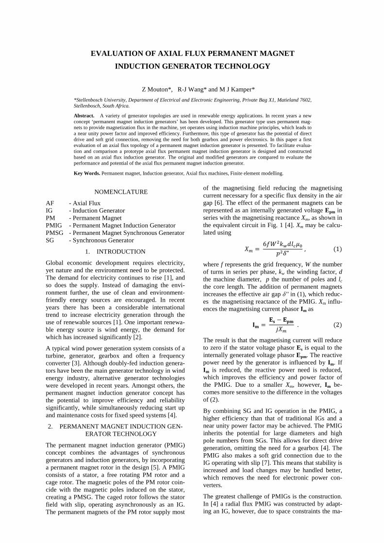
In [9] the differences and advantages of magnetically coupled and decoupled PMIG topologies are consid-ered and explained. In a magnetically coupled PMIG the stator, PM rotor and cage rotor are linked mag-netically, as shown in its equivalent circuit in Fig. 1. Fig. 3 shows the flux contours of a magnetically cou-pled AF-PMIG. For a magnetically decoupled or split PMIG the SG and IG components of the PMIG are not linked magnetically, only mechanically, as shown in Fig. 2 and Fig. 4. In this paper the focus is on the decoupled configuration.
Fig. 1: Equivalent circuit of a coupled PMIG [4].
Fig. 2: Equivalent circuit of a decoupled PMIG.
Fig. 3: Flux contours of magnetically coupled AF-PMIG
Fig. 4: Flux contours of magnetically decoupled AF-PMIG
3. DESIGN OF AN AF-PMIG PROTOTYPE
In order to evaluate and facilitate comparison, the AF-PMIG prototype is designed based on an existing 6-pole, 4 kW AF-IG.
3.1 Finite Element Modeling
To allow for comparison between the PMIG and the unmodified AF-IG machine it was decided to design the machines for similar flux densities in the air gap. In order to determine the dimensions for the perma-nent magnets at a specific flux density for a specific air gap, finite element method analysis is used. All finite element simulations are done using Magnet Version 7.1.1, and analysis of the data is done using FFT theory in MATLAB.
To determine the flux density in the IG a static solu-tion is used with the no-load current, for under no-load conditions the no-load current is a good approx-imation of the magnetising current. In order to obtain the no-load current a transient analysis is done, using 400 V line voltage sources. The 400 V is the rated voltage of the machine, and therefore the equivalent of the voltage the magnets have to generate for ideal operation. The transient solution indicated a steady-state no-load current of 4.7 Arms per phase.
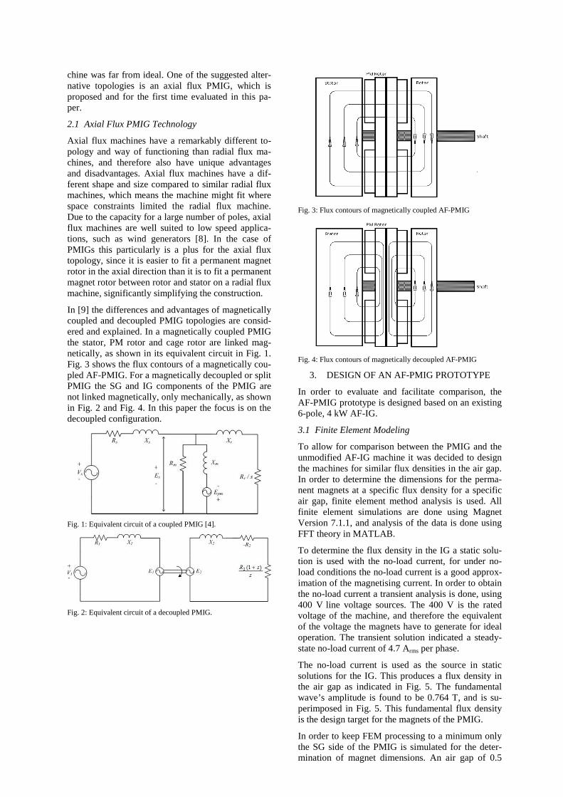
The no-load current is used as the source in static solutions for the IG. This produces a flux density in the air gap as indicated in Fig. 5. The fundamental wave’s amplitude is found to be 0.764 T, and is su-perimposed in Fig. 5. This fundamental flux density is the design target for the magnets of the PMIG.
In order to keep FEM processing to a minimum only the SG side of the PMIG is simulated for the deter-mination of magnet dimensions. An air gap of 0.5
mm is chosen and used in all simulations of the SG. Grade N48 NdFeB magnets are used in the simula-tion, design and construction of the AF-PMIG, and are the only source of magnetic flux for the simula-tions. The FE simulations indicate that magnets of pole pitch 0.676 and thickness 9 mm, and with a PM rotor disk thickness of 10 mm produce a flux density of 0.775 T. These dimensions are chosen as the de-sired magnet design and PM rotor disk design.
The AF-PMIG is also simulated to determine how well the chosen magnet design will function in the complete PMIG design. After the magnets were or-dered, however, a mechanical design change was made increasing the PM rotor disk’s thickness to 11 mm. Therefore a higher flux density is expected. To compensate for this the air gap is increased to lower the flux density to the designed 0.764 T, based on the simulation results of the AF-PMIG. The simulation model used is shown in Fig. 6, with the stator, PM rotor and cage rotor indicated on the diagram.
Simulations of the decoupled AF-PMIG with stator, caged rotor, and PM rotor with rotor disks of thick-ness 11 mm indicate that an air gap of 4 mm on both the SG and IG side of the PM rotor is desirable. It produces flux densities of 0.772 T and 0.766 T on the IG and SG side respectively. These flux densities are sufficient to operate the decoupled AF-PMIG at 400 V, using approximately no magnetising current under no-load conditions. Fig. 7 shows the FE model of the decoupled AF-PMIG, with a field line plot and shad-ed flux density plot. From the flux contours in Fig. 7 can be seen that the armature reaction effect of the stator on the cage rotor is negligible.
For the purposes of this paper both coupled and de-coupled PMIGs are designed, but only the decoupled configuration is built and tested. To attain the decou-pled configuration, magnets are placed with opposing polarities on either side of the PM rotor. To switch to the coupled configuration the PM rotor disks merely need to be shifted by one pole, i.e. 60°, to have at-tracting polarities on both sides of the PM rotor disks.
Simulations of the coupled AF-PMIG with stator, caged rotor, and PM rotor (with rotor disks of thick-ness 11 mm) indicate that an air gap of 8 mm on both the SG and IG sides of the PM rotor is desirable. This produces flux densities of 0.778 T and 0.772 T on the IG and SG side respectively. With such a large air gap one can, however, expect the flux to act differ-ently from what the FE analysis indicates, because the simulations are under ideal conditions which can-not be assured in reality. Fig. 8 shows the FE model of the coupled AF-PMIG, with a field line plot and shaded flux density plot.
Fig. 5: Flux density in the air gap of the IG at 400 V, shown with fundamental wave superimposed.
Fig. 6: Linear FE model of AF-PMIG.
Fig. 7: Field and shaded flux density plot of decoupled AF-PMIG.
Fig. 8: Field and shaded flux density plot of coupled AF-PMIG.
3.2 Construction of AF-PMIG prototype
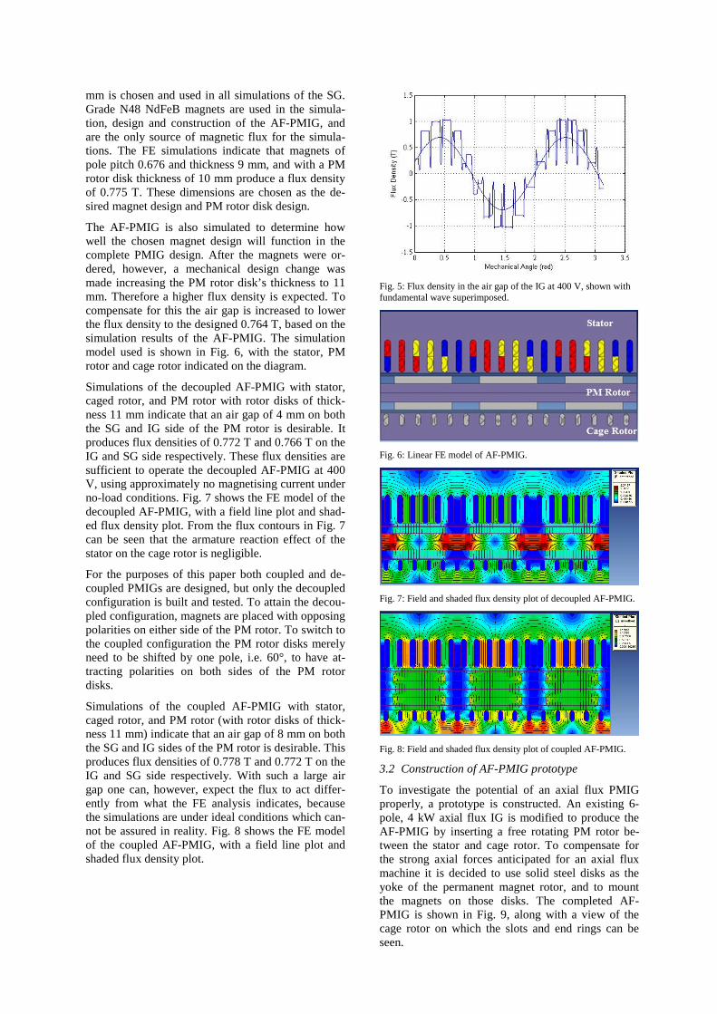
To investigate the potential of an axial flux PMIG properly, a prototype is constructed. An existing 6-pole, 4 kW axial flux IG is modified to produce the AF-PMIG by inserting a free rotating PM rotor be-tween the stator and cage rotor. To compensate for the strong axial forces anticipated for an axial flux machine it is decided to use solid steel disks as the yoke of the permanent magnet rotor, and to mount the magnets on those disks. The completed AF-PMIG is shown in Fig. 9, along with a view of the cage rotor on which the slots and end rings can be seen.
There are challenges unique to axial flux machines. The greatest is the considerable axial force. Bearings on the PM rotor and couplings on the shaft have to be designed to handle the strong axial force, especially in order to maintain small air gaps.
Fig. 9: Assembled AF-PMIG with cut-in of AF cage rotor.
4. EXPERIMENTAL INVESTIGATION OF IG AND PMIG
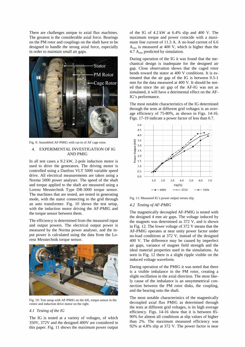
In all test cases a 9.2 kW, 2-pole induction motor is used to drive the generators. The driving motor is controlled using a Danfoss VLT 5000 variable speed drive. All electrical measurements are taken using a Norma 5000 power analyser. The speed of the shaft and torque applied to the shaft are measured using a Lorenz Messtechnik Type DR-3000 torque sensor. The machines that are tested, are tested in generating mode, with the stator connecting to the grid through an auto transformer. Fig. 10 shows the test setup, with the induction motor driving the AF-PMIG and the torque sensor between them.
The efficiency is determined from the measured input and output powers. The electrical output power is measured by the Norma power analyser, and the in-put power is calculated using the data from the Lo-renz Messtechnik torque sensor.
Fig. 10: Test setup with AF-PMIG on the left, torque sensor in the centre and induction drive motor on the right.
4.1 Testing of the IG
The IG is tested at a variety of voltages, of which 350V, 372V and the designed 400V are considered in this paper. Fig. 11 shows the maximum power output
of the IG of 4.2 kW at 6.4% slip and 400 V. The maximum torque and power coincide with a maxi-mum line current of 11.3 A. A no-load current of 6.6 Arms is measured at 400 V, which is higher than the 4.7 Arms predicted by simulation.
During operation of the IG it was found that the me-chanical design is inadequate for the designed air gap. Close observation shows that the caged rotor bends toward the stator at 400 V conditions. It is es-timated that the air gap of the IG is between 0.5-1 mm for the data measured at 400 V. It should be not-ed that since the air gap of the AF-IG was not as simulated, it will have a detrimental effect on the AF-IG’s performance.
The most notable characteristics of the IG determined through the tests at different grid voltages is an aver-age efficiency of 75-80%, as shown in Figs. 14-16. Figs. 17-19 indicate a power factor of less than 0.7.
Fig. 11: Measured IG’s power output versus slip.
4.2 Testing of AF-PMIG
The magnetically decoupled AF-PMIG is tested with the designed 4 mm air gaps. The voltage induced by the magnets was determined as 372 V, and is shown in Fig. 12. The lower voltage of 372 V means that the AF-PMIG operates at near unity power factor under no-load conditions at 372 V, instead of the designed 400 V. The difference may be caused by imperfect air gaps, variance of magnet field strength and the ideal material properties used in the simulations. As seen in Fig. 12 there is a slight ripple visible on the induced voltage waveform.
During operation of the PMIG it was noted that there is a visible imbalance in the PM rotor, creating a slight oscillation in the axial direction. The most like-ly cause of the imbalance is an unsymmetrical con-nection between the PM rotor disks, the coupling, and the bearing onto the shaft.
The most notable characteristics of the magnetically decoupled axial flux PMIG as determined through the tests at different grid voltages, is its high average efficiency. Figs. 14-16 show that it is between 85-90% for almost all conditions at slip values of higher than 2%. The maximum measured efficiency was 92% at 4.8% slip at 372 V. The power factor is near
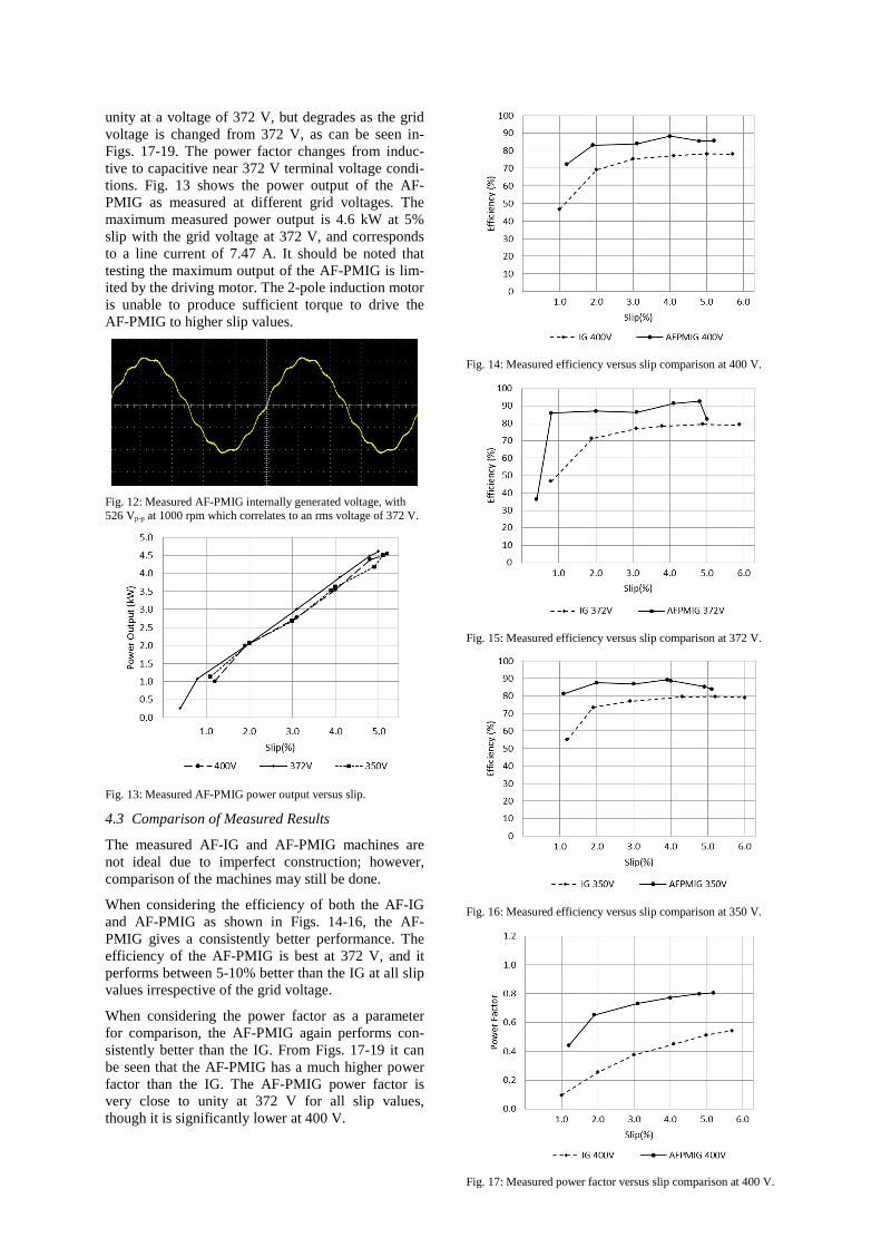
unity at a voltage of 372 V, but degrades as the grid voltage is changed from 372 V, as can be seen in-Figs. 17-19. The power factor changes from induc-tive to capacitive near 372 V terminal voltage condi-tions. Fig. 13 shows the power output of the AF-PMIG as measured at different grid voltages. The maximum measured power output is 4.6 kW at 5% slip with the grid voltage at 372 V, and corresponds to a line current of 7.47 A. It should be noted that testing the maximum output of the AF-PMIG is lim-ited by the driving motor. The 2-pole induction motor is unable to produce sufficient torque to drive the AF-PMIG to higher slip values.
Fig. 12: Measured AF-PMIG internally generated voltage, with 526 Vp-p at 1000 rpm which correlates to an rms voltage of 372 V.
Fig. 13: Measured AF-PMIG power output versus slip.
4.3 Comparison of Measured Results
The measured AF-IG and AF-PMIG machines are not ideal due to imperfect construction; however, comparison of the machines may still be done.
When considering the efficiency of both the AF-IG and AF-PMIG as shown in Figs. 14-16, the AF-PMIG gives a consistently better performance. The efficiency of the AF-PMIG is best at 372 V, and it performs between 5-10% better than the IG at all slip values irrespective of the grid voltage.
When considering the power factor as a parameter for comparison, the AF-PMIG again performs con-sistently better than the IG. From Figs. 17-19 it can be seen that the AF-PMIG has a much higher power factor than the IG. The AF-PMIG power factor is very close to unity at 372 V for all slip values, though it is significantly lower at 400 V.
Fig. 14: Measured efficiency versus slip comparison at 400 V.
Fig. 15: Measured efficiency versus slip comparison at 372 V.
Fig. 16: Measured efficiency versus slip comparison at 350 V.
Fig. 17: Measured power factor versus slip comparison at 400 V.
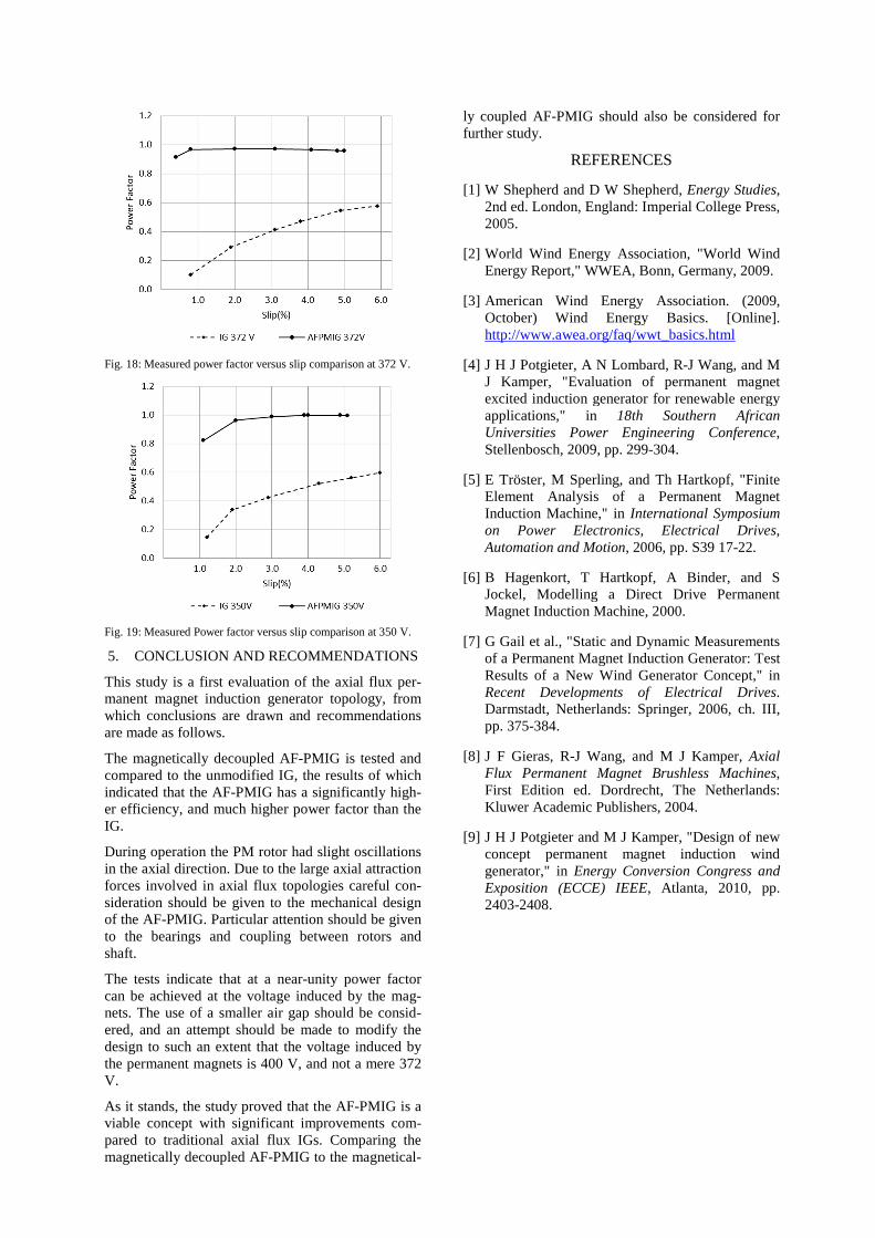
Fig. 18: Measured power factor versus slip comparison at 372 V.
Fig. 19: Measured Power factor versus slip comparison at 350 V.
5. CONCLUSION AND RECOMMENDATIONS
This study is a first evaluation of the axial flux per-manent magnet induction generator topology, from which conclusions are drawn and recommendations are made as follows.
The magnetically decoupled AF-PMIG is tested and compared to the unmodified IG, the results of which indicated that the AF-PMIG has a significantly high-er efficiency, and much higher power factor than the IG.
During operation the PM rotor had slight oscillations in the axial direction. Due to the large axial attraction forces involved in axial flux topologies careful con-sideration should be given to the mechanical design of the AF-PMIG. Particular attention should be given to the bearings and coupling between rotors and shaft.
The tests indicate that at a near-unity power factor can be achieved at the voltage induced by the mag-nets. The use of a smaller air gap should be consid-ered, and an attempt should be made to modify the design to such an extent that the voltage induced by the permanent magnets is 400 V, and not a mere 372 V.
As it stands, the study proved that the AF-PMIG is a viable concept with significant improvements com-pared to traditional axial flux IGs. Comparing the magnetically decoupled AF-PMIG to the magnetical-
ly coupled AF-PMIG should also be considered for further study.
REFERENCES
[1] W Shepherd and D W Shepherd, Energy Studies, 2nd ed. London, England: Imperial College Press, 2005.
[2] World Wind Energy Association, "World Wind Energy Report," WWEA, Bonn, Germany, 2009.
[3] American Wind Energy Association. (2009, October) Wind Energy Basics. [Online]. http://www.awea.org/faq/wwt_basics.html
[4] J H J Potgieter, A N Lombard, R-J Wang, and M J Kamper, "Evaluation of permanent magnet excited induction generator for renewable energy applications," in 18th Southern African Universities Power Engineering Conference, Stellenbosch, 2009, pp. 299-304.
[5] E Tröster, M Sperling, and Th Hartkopf, "Finite Element Analysis of a Permanent Magnet Induction Machine," in International Symposium on Power Electronics, Electrical Drives, Automation and Motion, 2006, pp. S39 17-22.
[6] B Hagenkort, T Hartkopf, A Binder, and S Jockel, Modelling a Direct Drive Permanent Magnet Induction Machine, 2000.
[7] G Gail et al., "Static and Dynamic Measurements of a Permanent Magnet Induction Generator: Test Results of a New Wind Generator Concept," in Recent Developments of Electrical Drives. Darmstadt, Netherlands: Springer, 2006, ch. III, pp. 375-384.
[8] J F Gieras, R-J Wang, and M J Kamper, Axial Flux Permanent Magnet Brushless Machines, First Edition ed. Dordrecht, The Netherlands: Kluwer Academic Publishers, 2004.
[9] J H J Potgieter and M J Kamper, "Design of new concept permanent magnet induction wind generator," in Energy Conversion Congress and Exposition (ECCE) IEEE, Atlanta, 2010, pp. 2403-2408.