european action plan for the prevention of runway excursions · european action plan for the...
TRANSCRIPT


European Action Plan for the Prevention of Runway Excursions - Released Edition 1.0 - January 2013 75
Appendix F AircrAft MAnufActurers
Manufacturers of aircraft must meet specific minimum criteria when it comes to certifying aircraft for use by the aircraft operators. It is recognised by the manufacturers that the information for certification does not cover all aspects of the aeroplane operations and as such they provide additional documents and information such as Flight Crew Operating Manuals, Flight Crew Training Manuals, Flight Crew Information Bulletins, Flight Opera-tion Technical Bulletins, and material during symposiums, conferences, performance engineer training classes, flight crew training.
Many of these publications contain procedures and infor-mation that address issues that have been identified as causal factors in runway excursions. However not all manufacturers provide the same amount or type of infor-mation. Below are recommendations for what manufac-turers should provide to help address issues associated with runway excursions. It is recognised that much of the information in the list below has been supplied by many but not necessarily all the manufacturers of the aeroplanes.
Takeoff and Landing Performance Presentation
Recommendation 3.5.1 Aircraft manufacturers should present takeoff and landing performance information in similar (common and shared) termi- nology and to agreed standards.
Significant progress and agreement as to terminology and standards was accomplished during the work of the United States FAA Takeoff and Landing Performance Assessment (TALPA) Aviation Rulemaking Committee (ARC) activity that occurred in 2008 and 2009. In this activity six of the major manufacturers worked with the FAA, aircraft operators, business jet operators, airport operators, and other industry interest groups to recom-mend a standard terminology for reporting and evalu-ating runways conditions when the runway is not dry and criteria for manufacturers to use when computing the aeroplanes performance information.
The current status of the recommendations from this activity is that the TALPA ARC recommendations have been issued by the FAA using advisory material. Some aircraft manufacturers have implemented the recom-mendations and so they are in use by some aircraft oper-ators. Airbus has changed the way it provides data in
their operating documents for the bulk of the fleet to use terminology and standards consistent with the TALPA ARC recommendations. Boeing has used the recom-mendations in creating the certification and operational data for their new aeroplane programs (787 and 747-8) and provides aircraft operators on an as requested basis the information necessary to adjust their landing perfor-mance information to meet the recommendations.
It is recommended that other certification agencies consider the work done during the FAA TALPA ARC if/when they change reporting terminology and methods or change standards for computing the performance information.
Runway Conditions and Aeroplane Performance
Recommendation 3.5.2 Training material promul-gated by aircraft manufacturers should empha-size the necessity of making best use of runway length available when conditions are uncertain or when runways are wet or contaminated by applying full braking devices, including reverse thrust, until a safe stop is assured.
This type of information is often included in the manu-facturer’s FCOM or FCTM with supplemental information possibly in bulletins or magazine articles.
An example of a manufacturer’s guidance on operating on wet or contaminated runways is provided later in this appendix.
Real Time Performance Monitoring and Warning Systems
Recommendation 3.5.3 On-board real time perfor- mance monitoring and warning systems that will assist the flight crew with the land/go-around decision and warn when more deceleration force is needed should be made widely available.
Part of the tools for excursion prevention is improved technology to help the pilot with the following decisions: to proceed to destination or divert, to land or go-around, or to apply all deceleration devices to their maximum

European Action Plan for the Prevention of Runway Excursions - Released Edition 1.0 - January 201376
Appendix F AircrAft MAnufActurers
utilisation. Different systems are currently available or in development by some manufacturers and 3rd party vendors to use existing technology to provide the flight crew information to assist with these decisions.
Landing Distance Calculations
Recommendation 3.5.4 The aviation industry should develop systems and flight crew manuals to help flight crews calculate landing distances reliably.
The aviation industry has changed greatly in the past decade as to how the calculation of performance in general and landing distances in particular is done. In the late 90s ACARS systems and laptops started showing up in the cockpit. The information the flight crew obtains from these systems is computed based on crew input information such as airport/runway, weather conditions, wind, runway condi-tions, approach type etc.
These systems replace the need for crew to do multiple hand calculations, flipping through paper charts and adding/subtracting/interpolating in cumbersome tables and charts. Often because of the number of computations required flight crew relied on quick checks of the numbers or didn’t do the appropriate performance checks at all.
With the aforementioned ACARS systems and on-board performance programs it is much easier for the flight crew to get an appropriate answer with less exposure to error. It is also easier for the crew to look at multiple scenarios so they can have a plan in the event they obtain additional information late in the approach that the runway has dete-riorated.
Manufacturers of these devices and methods are continu-ally searching for better ways to do this and in this very competitive business there is no doubt that continuous improvement will continue.
The availability of such interactive systems however does not discharge aircraft manufacturers and operators from presenting the performance information in an intuitive format that is foolproof to use. This becomes even more important when the performance tables are only used very occasionally as a backup means to an electronic system.
Data Checks
Recommendation 3.5.5 Electronic Flight Bag manufacturers and providers (class 1/2/3) should enable the flight crew to perform independent determination of takeoff data and to implement where possible an automatic crosscheck to en-sure correct insertion of the takeoff data in the avionics. Standard Operating procedures should be developed to support this crosscheck.
Manufacturers of EFBs are encouraged to investigate to what degree they can create simple crosschecks between various data sources to ensure the correct information is being used in the calculation of the takeoff data. A typical error that has caused safety problems in the past has been the use of incorrect weights in computing takeoff speeds.
Any means of minimising the sources of such error has to consider human factors aspects of the concerned interfaces and how they integrate into the specific cockpit environ-ment in which they are meant to be used. An example for a human factor driven solution is to require ZFW only as the input to the FMC instead of giving the option of input-ting either ZFW or TOW. Another example is removing the weight used in the previous calculation, which requires the flight crew to input the weight for the current flight each time.
Another approach to reducing mistakes are gross-error checks, which must rely on totally independent data sources to validate consistency. An example of a gross-error check is the comparison of the maneuvering speeds calcu-lated independently and from different sources by an EFB and the FMC.
Example guidance material may be found in the FAA AC 120-76A, “Guidelines for the Certification, Airworthi-ness, and Operational Approval of Electronic Flight Bag Computing Devices” and EASA AMC 20-25, “Approval of Electronic Flight Bags”.

European Action Plan for the Prevention of Runway Excursions - Released Edition 1.0 - January 2013 77
Flight Crew Procedures
Recommendation 3.5.6 Manufacturers should have clear flight crew procedures required to attain the published takeoff and landing performance.
The manufacturer’s performance presented to flight crew should clearly include the basis for the calculations. This would include items like the following:
n what level of reverse thrust was assumed,n what is the assumption of the wheel braking,n is the data factored or not,n what is the air distance allowance in the data.
FCOM procedures and flight crew training manual recom-mendations should also be consistent with the assump-tions in the data. If the data assumes prompt initiation of reverse thrust, then the procedures should require this, etc.
Maximum Crosswind
Recommendation 3.5.7 Maximum crosswind data published by aircraft manufacturers should be based upon one consistent and declared method of calculation.
The maximum acceptable crosswind depends on the aircraft capabilities and the runway conditions, but also in the personal limits of the flight crew depending on their experience. A consistently determined maximum cross-wind recommendation by aircraft manufacturers would be a good basis for a pilot to determine his personal limit from.
At this time however, manufacturers supply recommended crosswind maximums based on the assumptions they consider appropriate. The assumptions include things like:
n modeling for different runway conditions,n consideration of engine failure or not,n assumed centre of gravity position,n flight technique (crab, sideslip), etc.
This is because current methods for determining recom-mended or limitations on crosswind are not part of the certification basis for the aeroplanes, and only a demon-strated value on a dry runway is required in the AFM.
It is doubtful that manufacturers will come to a consensus on this item without regulatory guidance as in many cases there are fundamental differences in philosophy between manufacturers. A starting point for harmonisation would be for manufacturers to agree on using the description of the runway and braking action such as was accomplished for performance computations for the TALPA ARC.
The development of regulatory guidance in this field should include manufacturer consultation to ensure technical and economical feasibility.
Lessons Learned
Recommendation 3.5.8 Manufacturers should monitor and analyse all (worldwide) runway ex-cursions involving the aeroplanes they support and share the lessons learned.
The reporting and investigation of aircraft accidents and incidents is regulated by ICAO Annex 13. The results of such investigations are sometimes shared publicly. However, due to their much higher rate of occurrence much more can be learned from precursor events if they are identified as such and acted upon.
Some manufacturers review yearly or bi-yearly the signifi-cant accidents and incidents as well as the causal factors and issues highlighted by these events. This can be done at meetings and conferences attended by operators, and in manufacturer publications like bulletins, changes in procedures or other information.

European Action Plan for the Prevention of Runway Excursions - Released Edition 1.0 - January 201378
Appendix F AircrAft MAnufActurers
Information on the TALPA ARC
The TALPA ARC was tasked with an exhaustive review of safety issues of operations on contaminated runways and recommending modified FAA regulations, which would be retroactively applicable to all existing aircraft.
The proposals for regulatory changes concerning transport category aircraft put forward to the FAA by the ARC were oriented along three main axes:
n Standards for runway condition reporting (FAR139)n Definition of operational landing performance compu-
tation (FAR25/26)n Operational Rules (FAR121)
The committee also covered FAR23/91/91K/135 operations, which are not further addressed here.
The following aspects were outside of the scope of the FAA TALPA ARC mandate:
n Assessment of landing with in-flight failures,n Overweight landing without failures,n Automatic landing distances,n Dispatch landing distances.
The exclusion of dispatch was made to minimise the economical impact of the proposed changes. Furthermore, the introduction of a more operationally representative assessment of landing distances to be used for dispatch is not considered to constitute a significant improvement in safety levels, while accurate in-flight landing distance assessments are accepted as being the major means to reduce exposure to runway excursions at landing. Even so, for the long term, the need to review dispatch landing distances for consistency with the time of arrival require-ments was acknowledged by TALPA ARC in its submission to the FAA.
The concepts detailed in the following are those proposed for aircraft that will be certified under the FAA TALPA ARC rules. The TALPA ARC rules also mandate that landing distances in line with the spirit of the proposal are published for all existing aircraft still supported by the manufacturer, albeit with less stringent requirements and with an increased grace period. For non-supported aircraft a set of fixed and conservative factors to be applied to the AFM dispatch data are provided by the regulator.
The TALPA ARC submitted its proposals to the FAA in May 2009, who will translate them into a Notice of Proposed Rulemaking (NPRM). In parallel, a field trial was launched with selected airports and operators to further validate the Runway Condition Assessment Matrix. It is not expected that the NPRM will be published before 2013 to 2015, to be followed by a mandatory comment period of at least 6 months. The proposals included a grace period for compli-ance of existing aircraft of two years. However, several manufacturers and countries have taken on board signifi-cant elements of the TALPA ARC work for their publications and reporting respectively.
Operational RulesChallenges
Today, most operational regulations make a very generic statement regarding the need to assess landing perfor-mance in flight (“the commander must satisfy himself/herself that, according to the information available to him/her, the weather at the aerodrome and the condition of the runway intended to be used should not prevent a safe approach [and] landing”), which does not detail the criteria and factors to be taken into account for the determination of a safe landing distance.
The lack of clear direction has led to aircraft operator operations departments filling the regulatory deficit with a variety of policies of their own initiative (or sometimes under requirement from their national Operational Authori-ties). Such variety of aircraft operator policies was observed by the FAA in the aftermath of the Chicago-Midway acci-dent, and subsequently led to the publication of SAFO and AC. These documents made recommendations applicable to US operators to perform in flight landing performance assessment, including the manner in which the Operational Landing Distance should be derived, and instigated the additional 15% margin, except in emergency situations.
Proposals
n Dispatch landing distance assessment The FAA TALPA ARC has recognised that the current
dispatch landing distance, in particular on a wet smooth runway, might, in some cases, like hot & high elevation airports or descending runway slope, deliver unsatisfactory margins. This is why an in-flight landing performance assessment will be required to be made systematically as part of the approach preparation.

European Action Plan for the Prevention of Runway Excursions - Released Edition 1.0 - January 2013 79
n In-flight landing distance assessment The proposed FAR 121 operational rules will mandate a
systematic in-flight landing distance assessment based on a Factored Operational Landing Distance (FOLD) equal to 115% of the OLD published for the prevailing conditions (100% if emergency or in-flight failure):
This 15% FOLD increment serves to provide a margin to cover variations in parameters entering in the OLD calculation, like for example:n The variability of runway friction due to evaluation
and reporting of surface contamination, changing runway condition due to weather and in the case of wet runway surface issues such as texture loss and precipitation rate
n The variability in the flare execution or deceleration means application by the pilot
n The variability in touchdown speed due to turbu-lence or the impact of cross-wind
n Use of Autobrake The proposal of operational rules includes an exemp-
tion regarding the application of the 15% margin when using autobrake:n If the FOLD for manual landing is less than the
Landing Distance Available (LDA)n And if the OLD for automatic braking is less than the
LDAn Then the FOLD for automatic braking may be longer
than the LDA
The rationale for this exemption is that the pilot can always override autobrake when required.
n Exemption from In-Flight Assessment It will be permitted to omit the in-flight assessment for
landing on the runway planned at dispatch only if:n Dispatch was performed
for DRY (or worse), and if at time of approach prepara-tion a DRY runway and no worse conditions than the standard ones considered for dispatch are reported (e.g. no tailwind when zero wind considered for dispatch, no higher VAPP than usual)
n Dispatch performed for WET, and if at time of approach preparation a WET runway and no worse conditions than the ones considered for dispatch are reported and the runway is maintained to the stan-dards defining grooved or PFC runways in AC 150-5320.
Runway Condition ReportingChallenges
There is not currently a single worldwide standard for runway condition reporting.
Most frequently, the type of contaminant (and its depth when available) is reported, although the means for measurement, the threshold for reporting in terms of runway coverage, as well as the format, terminology and resolution of the reported information vary with local ATC practices.
Where runway friction measurements by dedicated vehicles are available, such friction values are sometimes reported to flight crew, although manufacturers do not provide any correlation of runway friction measured with a vehicle or a trailer with aircraft performance capabilities on the same surface. Some aircraft operators and local regulators have developed their own guidance.

European Action Plan for the Prevention of Runway Excursions - Released Edition 1.0 - January 201380
Appendix F AircrAft MAnufActurers
In North America, after landing, pilots usually report to ATC their assessment of braking action on a scale from GOOD to POOR to ATC, and thus to following aircraft. This may occur spontaneously when braking action is found to be lower than expected for the reported runway condition, or on request by the tower.
Proposals
The centrepiece of the regulatory proposals is what became known in the work group as the “runway condition matrix”. Its structure adheres to the existing ICAO runway codes and shows seven runway condition levels associated to codes from 0 (for nil braking action) to 6 (for dry), where each runway condition code (except 0) is matched with a corre-sponding aircraft performance level.
Different criteria of runway condition reporting can be used as entry points for the determination of the applicable aircraft performance level. These reporting criteria are:
n Contaminant type and depth,n Pilot braking action report (PIREP), andn Runway friction measurement (Mu (μ)).
The latter two types of report should be used only for downgrading of a runway from a friction category basi-cally identified via contaminant type and depth. Pilots will be informed of contamination on the runway as soon as in excess of 10% of the runway surface is contaminated, while runway condition codes will be reported for each third of the runway when more than 25% of the entire runway surface is contaminated. If a friction measure-ment or reports from preceding aircraft’s pilots (PiReps) indicate that the friction levels have dropped below those expected for the type of contaminant on the runway, the airport should report a lower condition code in line with the observed friction or braking action.
The information to be transmitted to the flight crew includes:
n The runway condition code for each third of the runwayn The type and depth of the contaminant and percentage
of coverage in 25% increments (to avoid currently used terms such as “thin” and “patchy”)
n The PIREPs when available.

European Action Plan for the Prevention of Runway Excursions - Released Edition 1.0 - January 2013 81
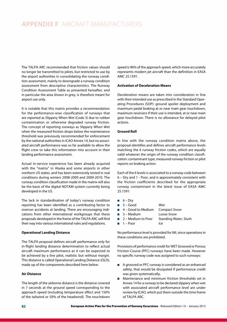
AIRPORT RUnWAy COnDITIOn ASSESSMEnT
Assessment CriteriA downgrAde Assessment CriteriA
code runwAy condition description Mu (μ)decelerAtion And directionAl control observAtion
PIREP
6 n Dry - -
5
n Wet (includes water 1/8” or n Frost
1/8” or less depth of:n Slushn Dry Snown Wet Snow
Braking deceleration is normal for the wheel braking effort applied. Directional control is normal
Good
4 15°C and Colder outside air temperature:n Compacted Snow
Brake deceleration and controllabi-lity is between Good and Medium.
Good to Medium
3
n Wet (“Slippery when wet runway”)n Dry Snow or Wet Snow (Any Depth) over Compacted Snow
Greater than 3 mm (1/8”) depth of :n Dry Snown Wet Snow
Warmer than -15°C outside air temperature:n Compacted Snow
Braking deceleration is noticeably reduced for the wheel braking effort applied. Directional control may be noticeably reduced.
Medium
2Greater than 1/8” depth of :n Watern Slush
Brake deceleration and controllabi-lity is between Medium and Poor. Potential for hydroplaning exists.
Medium to Poor
1 n Ice
Braking deceleration is significantly reduced for the wheel braking effort applied. Directional control may be significantly reduced.
Poor
0n Wet ice n Water on top of Compact Snow2
n Dry Snow or Wet Snow over Ice2
Braking deceleration is minimal to non-existent for the wheel braking effort applied. Directional control may be uncertain.
Nil
40 or Higher
39 to 30
29 to 21
20 or lower
European Action Plan for the Prevention of Runway Excursions - Released Edition 1.0 - January 201382
Appendix F AircrAft MAnufActurers
The TALPA ARC recommended that friction values should no longer be transmitted to pilots, but restricted to use by the airport authorities in consolidating the runway condi-tion assessment, mainly to downgrade a runway condition assessment from descriptive characteristics. The Runway Condition Assessment Table as presented hereafter, and in particular the area shown in grey, is therefore meant for airport use only.
It is notable that this matrix provides a recommendation for the performance-wise classification of runways that are reported as Slippery When Wet (Code 3) due to rubber contamination or otherwise degraded runway friction. The concept of reporting runways as Slippery When Wet when the measured friction drops below the maintenance threshold was previously recommended for enforcement by the national authorities in ICAO Annex 14, but no associ-ated aircraft performance was so far available to allow the flight crew to take this information into account in their landing performance assessment.
Actual in-service experience has been already acquired with the “matrix” in Alaska and some airports in other northern US states, and has been extensively tested in real conditions during winters 2008-2009 and 2009-2010. The runway condition classification made in the matrix will also be the basis of the digital NOTAM system currently being developed in the US.
The lack in standardisation of today’s runway condition reporting has been identified as a contributing factor to overrun accidents at landing. There are encouraging indi-cations from other international workgroups that these proposals developed in the frame of the TALPA ARC will find their way into various international rules and regulations.
Operational Landing Distance
The TALPA proposal defines aircraft performance only for in-flight landing distance determination to reflect actual aircraft maximum performance as it can be expected to be achieved by a line pilot, realistic but without margin. This distance is called Operational Landing Distance (OLD), made up of the components described here below.
Air Distance
The length of the airborne distance is the distance covered in 7 seconds at the ground speed corresponding to the approach speed (including temperature effect and 150% of the tailwind or 50% of the headwind). The touchdown
speed is 96% of the approach speed, which more accurately represents modern jet aircraft than the definition in EASA AMC 25.1591.
Activation of Deceleration Means
Deceleration means are taken into consideration in line with their intended use as prescribed in the Standard Oper-ating Procedures (SOP): ground spoiler deployment and maximum pedal braking at or near main gear touchdown, maximum reversers if their use is intended, at or near main gear touchdown. There is no allowance for delayed pilot actions.
Ground Roll
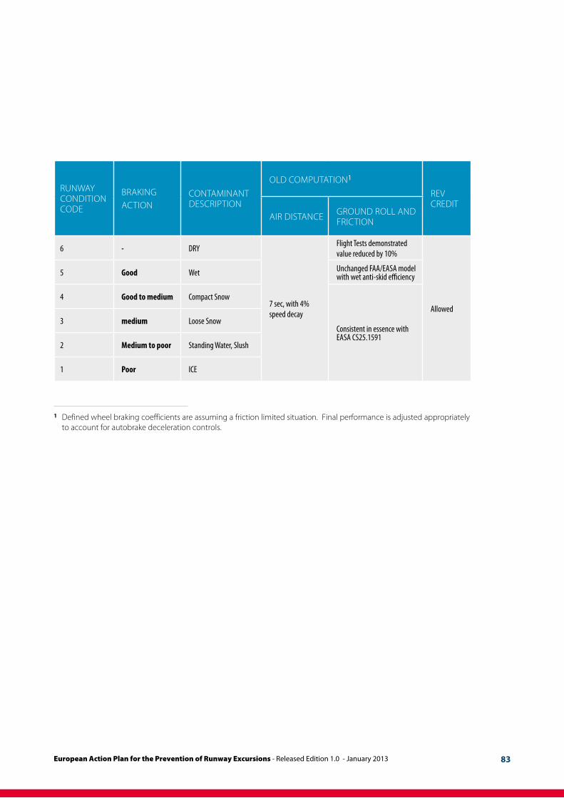
In line with the runway condition matrix above, the proposal identifies and defines aircraft performance levels matching the 6 runway friction codes, which are equally valid whatever the origin of the runway condition classifi-cation: contaminant type, measured runway friction or pilot reports on braking action.
Each of the 6 levels is associated to a runway code between 6 – Dry and 1 - Poor, and is approximately consistent with the friction coefficients described for the appropriate runway contaminant in the latest issue of EASA AMC 25.1591:
n 6 – Dry n 5 – Good Wetn 4 – Good to Medium Compact Snown 3 – Medium Loose Snow n 2 – Medium to Poor Standing Water, Slushn 1 – Poor Ice
No performance level is provided for Nil, since operations in these conditions are prohibited.
Provisions of performance credit for WET Grooved or Porous Friction Course (PFC) runways have been made. However no specific runway code was assigned to such runways:
n A grooved or PFC runway is considered as an enhanced safety, that would be dissipated if performance credit was given systematically,
n Maintenance and minimum friction thresholds set in Annex 14 for a runway to be declared slippery when wet with associated aircraft performance level are under review by ICAO, which put them outside the time frame of TALPA ARC.
European Action Plan for the Prevention of Runway Excursions - Released Edition 1.0 - January 2013 83
1 defined wheel braking coefficients are assuming a friction limited situation. final performance is adjusted appropriately to account for autobrake deceleration controls.
runwAy condition code
brAkingAction
contAMinAnt description
old coMputAtion1
rev credit
Air distAnce ground roll And friction
6 - DRY
7 sec, with 4% speed decay
Flight Tests demonstrated value reduced by 10%
Allowed
5 Good Wet Unchanged FAA/EASA model with wet anti-skid efficiency
4 Good to medium Compact Snow
Consistent in essence with EASA CS25.1591
3 medium Loose Snow
2 Medium to poor Standing Water, Slush
1 Poor ICE

European Action Plan for the Prevention of Runway Excursions - Released Edition 1.0 - January 201384
Appendix F AircrAft MAnufActurers
An example of a manufacturer’sguidance for operating on wet or contaminated runways.
note:The following information is an example of manufacturer’s guid-ance for operating on wet or contaminated runways. This infor-mation is an example only and may change. It will not be kept up to date.
Slippery Runway Landing Performance
When landing on slippery runways contaminated with ice, snow, slush or standing water, the reported braking action must be considered. Advisory information for reported braking actions of good, medium and poor is contained in the PI chapter of the QRH. The performance level associated with good is representative of a wet runway. The perfor-mance level associated with poor is representative of a wet ice covered runway. Also provided in the QRH are stopping distances for the various autobrake settings and for non-normal configurations. Pilots should use extreme caution to ensure adequate runway length is available when poor braking action is reported.
Pilots should keep in mind slippery/contaminated runway advisory information is based on an assumption of uniform conditions over the entire runway. This means a uniform depth for slush/standing water for a contaminated runway or a fixed braking coefficient for a slippery runway. The data cannot cover all possible slippery/contaminated runway combinations and does not consider factors such as rubber deposits or heavily painted surfaces near the end of most runways.
One of the commonly used runway descriptors is coeffi-cient of friction. Ground friction measuring vehicles typi-cally measure this coefficient of friction. Much work has been done in the aviation industry to correlate the friction reading from these ground friction measuring vehicles to aeroplane performance. Use of ground friction vehicles raises the following concerns:
n the measured coefficient of friction depends on the type of ground friction measuring vehicle used. There is not a method, accepted worldwide, for correlating the friction measurements from the different friction measuring vehicles to each other, or to the aeroplane’s braking capability.
n most testing to date, which compares ground fric-tion vehicle performance to aeroplane performance, has been done at relatively low speeds (100 knots or less). The critical part of the aeroplane’s deceleration characteristics is typically at higher speeds (120 to 150 knots).
n ground friction vehicles often provide unreliable read-ings when measurements are taken with standing water, slush or snow on the runway. Ground friction vehicles might not hydroplane (aquaplane) when taking a measurement while the aeroplane may hydroplane (aquaplane). In this case, the ground friction vehicles would provide an optimistic reading of the runway’s friction capability. The other possibility is the ground friction vehicles might hydroplane (aquaplane) when the aeroplane would not, this would provide an overly pessimistic reading of the runway’s friction capability. Accordingly, friction readings from the ground friction vehicles may not be representative of the aeroplane’s capability in aquaplaning conditions.
n ground friction vehicles measure the friction of the runway at a specific time and location. The actual runway coefficient of friction may change with changing atmospheric conditions such as temperature variations, precipitation etc. Also, the runway condition changes as more operations are performed.
The friction readings from ground friction measuring vehicles do supply an additional piece of information for the pilot to evaluate when considering runway condi-tions for landing. Crews should evaluate these readings in conjunction with the PIREPS (pilot reports) and the physical description of the runway (snow, slush, ice etc.) when planning the landing. Special care should be taken in evaluating all the information available when braking action is reported as POOR or if slush/standing water is present on the runway.
Wheel Brakes
Braking force is proportional to the force of the tyres on the runway and the coefficient of friction between the tyres and the runway. The contact area normally changes little during the braking cycle. The perpendicular force comes from aeroplane weight and any downward aerodynamic force such as speedbrakes.
The coefficient of friction depends on the tyre condition and runway surface, (e.g. concrete, asphalt, dry, wet or icy).

European Action Plan for the Prevention of Runway Excursions - Released Edition 1.0 - January 2013 85
Automatic Brakes
Use of the autobrake system is recommended whenever the runway is limited, when using higher than normal approach speeds, landing on slippery runways, or landing in a crosswind.
For normal operation of the autobrake system select a deceleration setting. Settings include:
n MAX AUTO: Used when minimum stopping distance is required. Deceleration rate is less than that produced by full manual braking
n 3 or 4: Should be used for wet or slippery runways or when landing rollout distance is limited
n 1 or 2: These settings provide a moderate deceleration suitable for all routine operations.
Experience with various runway conditions and the related aeroplane handling characteristics provide initial guidance for the level of deceleration to be selected.
Criteria to be fulfilled by aneffective runway excursionprevention system
The system should work in real time and continuously assess the position of the aircraft relative to the runway to which it performs the approach, as well as its actual energy level. The system should work in manual and automatic landing and manual and automatic braking. It should make a conservative but realistic assessment of the stop-ping distance required under the prevailing conditions for that energy level. It should compare the necessary distance with that available. It should alert the flight crew during the approach when a safe stop on the runway is not ensured. It should alert the flight crew during the ground roll when more deceleration is required. No runway overruns should occur with aircraft equipped with the system under condi-tions for which it is certified without an alert being trig-gered. The system should not generate alerts unnecessarily.
A system fulfilling these conditions permits the definition of clear procedures associated with the alerts (go-around, maximum braking and selection of max reverse thrust) that can, when applied, prevent runway excursions.
Example of procedures required to obtain published performance