etl-05'91 w ',,,d-a245 039 - defense technical information ... · etl-05'91 w...
TRANSCRIPT

ETL-05'91 W
',,,D-A245 039
use. of Interim TerrainD~ata to0 Populate Project
-35 1 's Database i nr)po rt of Ground
Force's Simulation
Kevin Backe
DTIQ11LECT[S JA28 19920
-January 19918
Reproduced FromBest Available Copy
Approved for pubblic release; distribution is unlimited.
921.24.042.U.S., Army Corps of En'gineers .Eng~ineer Topographic L~aboiatori~es920 70 LFort Belvoir, Virainia, 22060-5546 9200
1S
Destroy this report when no longer needed.Do not return it to the originator.
The findings in this report are not to be constried as an officialDepartment of the Army position unless so designated by' otherauthorized documents.
The citation in this report of trade names of commercially'svailableproducts does not constitute official endorsement or approval of theuse of such products.

REPORT DOCUMENTATION PAGE orm Appoc~rd
OAM8 No 0704--C 88
~ 06 ~ ~ q W~-ti~'4', o e .'qLh'.% b..Ot. to iVtir'ýN.Vcý Le.d0O'¶I ieote 0 elatet Ol 4,, ot" #,ft Of1 ItIht
1. AGENCYUSE ONLY (Leave blcnk) 1. R.PORT DATE 3. REPORT TYPE AND DATES COVEPEDJanuary 1991 Technical Report June - October 1990
4. TITLE AND SUBTITLE S. FUNO•NG NUMBERSUse of Interim Terra;n Data to Popu!ate Project 285 I'sDatabase in Support of Ground Forccs Simulation
G. AUTOR(S)
Kevin Backe
7. PERFORMING OR-ANIZATION NAME(S)'AND AORESS(Es) i. PERFORMING ORGANIZATION
REPORT NUMBER
U.S. Army Engineer Topographic LaboratoriesFort Belvoir, VA 22060-5546
ETL-0591
.SPONSORiNG/ MONITORING AGENCY NAME(S) AND AUPESS(ES) 10. SPONSORING/ MONITORING
Army Material Command AGENCY REPORT NUMBER
Project Manager for Training Devices (PM TRADE)ATf N: AMCPM-TND-ET
.12350 Research ParkwayOrlando FL 32826-3276 ........ ' .... . ......
IS. SUýPLtE MNTER;R NOTES
1!a. OI$1RIBUTION/AVAILABILI!Y STATEMENT 12b. DISTRIBUTION COOE
Approved for public release; distribution is unlimited.
13. ABS TRACT (Ma iim 2OQ'wo'd)
Project 2851 is a Department of Defense (DoD) program to develop a standard DoD simulator database andassociated transf )rmation software necessary to support a wide range of simulator applications., Project 2851is currently capa ile of directly inputting two standar:l Defense Mapping Agency (DMA) Digital TopographicData (DTD) prolucts, Digital Terrain Elevation Data (DTED) and Digital Feature Analysis Data (DFAD), topopulate its simulator database. This report presents the findings from a study on the potential use of a thirdDMA DTD product, Interim Terrain Data (ITD), to populate Project 285 I's database. ITD is compared toProject 2851's Standard Simulator database (SSDB) to determine the necessary transformation required toincorporate ITDI into the SSDB. ITD is a high resolution standard terrain feature database product currentlyavailable to the krmy; therefore, ITD should prove very useful to the simulation community especially forground forces si miulation applications.
!4. SUBJECT TERMI IS. NUMBeR 01' AGS
16
Project 2851, 1 iterim Terrain Data, ITD, Simulation i,. PRKIE CODE
1. SECURITY CLAISIFICATION 11. SECURITY rlASSIFtICATION It. (dCURITY CLA.-SIFICATION 20. LIMITATIONOF ABSTRACTOF REPORT .I Of THIS PAGEj Of ABSTRACT
"UNCLASSIFIE NCLASSIFIED. UNCLASSIFIED I UNLIMITED JNSNJS•O)'".Stndard Form 298 (Rev. 2-69)
28OS54bp e AMU 1t4 119-16

CONTENTS
TITLE PAGE
PREFACE v
1. INTRODUCTION 1
1.1 Purpose 1
1.2 Scope 1
1.3 Background 1
1.3.1 Standard DoD Simulator Digital Database/Common Transformation Program(Project 2851) 1
1.3.2 Rapidly Reconfigurable Data Base (RRDB) 1
1.3.3 Interim Terrain Data (ITD)
1.3.4 ETL's Participation in Project 2851/RRDB 2
2. FINDINGS 3
2.1 Content 3
2.2 Resolution 4
2.3 Accuracy 4
2.4 Data Density 5
'2.5 Minimum Polygon Size 5
2.6 Storage 7
2.7 Format and Coding Scheme 7
2.7, 1 ITD Format 7
2.7.2 SSDB Formats 7
2.7.3 lTD Coding Scheme 7
2.7.4 SSDB Coding Scheme 8
iii '.

Imin
CONTENTS (Continued)
TITLE PAGE
2.7.5 Conversion of ITD) into SSDB Format 8
2.7.6 Conversion of rfD into the FDC 8
2.8 Structure 8
2.9 Datum and Cell Size 8
2.10 lTD Area Coverage 9
3. CONCLUSION 9
REFERENCES 10
APPENDIX 11
iv

PREFACE
Under a Memorandum of Agreement (MOA), the U.S. Army Engineer Topographic Laboratories (ETL)Digital Concept and Analysis Center (DCAC) is providing technical support in the area of Mapping,Charting, and Geodesy (MC&G) to the Army Materiel Command's Project Manager for TrainingDevices (PM TRADE).
The author consulted with and received valuable input and comments from the followLif, ETLGeographic Sciences Laboratory personnel: Mr. Douglas Caldwell, Mr. Mark-Flood, Mr. John Hale,Mr. Richard Herrmann, Mr. Randall Karalus, and Mr. Kevin Muhm.
The work was performed during the period of June to. October 1990 under the supervision of Mr. JuanPerez, Chief, Standards Br.nch, and Mr. Francis Capece, Director, Digital Concepts and AnalysisCenter.
Colonel David F. Maune, EN, was Commander and Director, and Mr. Walter E. Boge was TechnicalDirector of the U.S. Army Engineer Topographic Laboratories during thiz report preparation.
A@esosion ?o• •
STI' GRA&Z
DTIC TAB QUnannounced 0Justifiontlo"
By,Distribution/
Availability Codes•Avail mdow.
Diet spe ta9

USE OF :NTERIM TERRAIN DATA TO POPULATE PROJECT 2851'S
DATABASE IN SUPPORT OF GROUND FORCES
1. INTRODUCTION
1.1 Purpose
The purpose of this report is to describe Interim Terrain Data (IrD) for the Army simulation andtraining community and to present a study comparing ITD to Project 285I's Standard Simulator Database(SSDB).
1.2 Scope
First, this report provides a description of Project 2851 and an assessment of lTD. Specifically, thefollowing ITD characteristics aie presented: centent, data resolution, azcuracy, data density, minimumpolygon size, and data storage requirements. Second, the report presents the results of a studycomparing ITiD to Project 2851/Rapidly Reconfigurable Data Base's (RRDB) SSDB. This studycompares lTD's format, coding scheme, and data structure with the SSDB's format, coding schedule andstructure.
1.3 Background
1.3.1 Standard DOD Simulator Digital Database/Common Transformation Program (Project28S1). Currently each simulator procured by the Department of Defer.se (DOIL has incorporated into itspurchase price the cost of developing its own database and transformation progr un(s). This results in aproliferation of nonstandard, incompatible databases and software, which is c-, dy for the Government interms of both recurripg development costs and maintenance costs.
Project 2851 is a tri-service program specifically designed to eliminate redundancy among DOD trainingsimulator databases and transformation software. The objective for Project 2851 is to develop a standardDOD simulator database and the associated transformation software necessary to support a wide range ofreal-time Image Generation (IG) systems. This Standard Simulator Database (SSDB) will be designedwith multiple Levels of Detail (LGD) (from 300 meters to 1 meter) reso ution in support of variousapplicatioas from high altitude flight simulation to ground forces simulation.
The Project 2851 Program will establish an operational facility, located at the Defense Mapping AgencyAerospace Center (DMAAC) in St. Louis, MO. This facility will function asa centrairepository fordigital terrain elevation data, cultural feature data, and model data for use by the DOD simulationcommunity.
1.3.2 Rapidly rteconflgurable Data Base (RRDB). The Rapidly Reconq1gurable Data Base is anadditional requirement levied ou Projec' 2851 specifying the capability to rapidly generate a standardsimulator database foi mission rehearsal from a larger selection of data sources. The two primary tasksassociated with RRDB are (1) ts ,pand the type of input sources to Project 2851's SSDB to includevarious fbrms of imagery, and an option to include new DMA cartographic sources; and (2) to provide aphoto-texture capability for both terrain and model data in support of newer, imagery-basedtrainingirehearsal systems.
I_

1.3.3 Interim Terrain Data (ITD). With the establishment of the RRDB initiative, a requirement wasinitiated to assess the utility of incorr,.rating HId into the SSDB to support ground forces trainingsimulation requirem#-its. Interim Terrain Data is a recently developed rtandard Defense MappingAgency (DMA) Digital Topographic Data (DTD) product. The ITD product was originally designed tosupport the Army's near-term (1989-1993+) tactical and analysis requirements for DTD products.
Interim Terrain Data is an enhanced softcopy representation of the information portrayed on the 1:50,000scale hardcopy Tactical Terrain Analysis Data Base 11TADB). Similarly, P1 arming Interim Terrain Data(PITD) is an enhanced softcopy reprasentation of the information portrayed on the 1:250,000 scalehardcopy Planning Terrain Analysis Data Base (PTADB). A one-degree by one-degree Digital TerrainElevation Data (DTED) level 1 cell is distributed with each ITD and each PITD call.
ITD and PITD are currently being produced by two different mnethods; one method uses cutographiccollection techniques, and the other metl&od uses photegrammetric collection techniques. Thecartographc method consists of digitizing each of the hardcopy -Terrain Analysis (TITADB or PTADB)overlays., One of the overlays, the Transportation overlay, is enhanced with additional road featuresprior to digitization. Feature and attribute information is then encoded into the unsymbolized vector Pinedata. The coding scheme employed is the Defense Mapping Agency Feature File (DMAFF).[I]
The photogrammetric method of producing ITD involves compiling ITD directly from stereo imagerysource. All the features are ollected and encoded with the appropriate DMAFF feature and attributecode information.
ITD is segregated into six thematic files. Three of the thematic files are "full areal coverage" featurefles containing the following terrain information: surface configuration (siope), vegetation, and surfacematerials (soils). (The term "full areal coverage" thematic files indicates all of the area within thesefiles' geographic bounds is classified with a slope, soils, or vegetation category.) The fourth th=Amticfeature file contains surface drainage features; and the remaining two thematic feature files containtransportation and obstacles information.
ri) and PITD cells are sized to match the dimensions of the coriesponding base maps. An T!D cellmatches the dimensions of a 1:50,000 scale Topographic Line Map (TLM), and a PITD cell matches thedim ions of the 1:250,000 scale Joint Operation Graphic (jOG). ITD and PITD are distributed touse. in DMA's Standard Linear Format (SLF).[2J ITD is currently available only on 9-track tape.How eer, the Army has stated a requirement for ITM on CD-ROM and DMA is currently investigatingdist buting IM on this media in the future.
1.3. ETL's Part-tiipation in Project 28S1I/RRDB. Under a Memorandum of Agreement (MOA), theU.S. Army Engineer Topoographic Laboratories (ETL) is supporting the Army Materiel Commzn,''s•Proj Manager for Training Devices (PM TRADE) wvith the development of. database generation
logies, and the creation of several prototype databases. Under tarms of the MOA, ETL is alsosche uled to conduct informadion meetings and briefings betwee the participant government agenciesand te prime 2851 contractor on data exchange formats, to provide terrain visualization demonstrations,and t provide reports pertaining to database development topics and studies. (31
[FrL's] Digital Concept and Analysis Center [DCACJ will work with PM TRADE andTRADOC personnel to assess the applicability of Interim Terrain Data (ITD) to meet theneed of the Army training community for sinm.lation of ,wround forces and to analyze theuse of Project 285l to meet these needs.
2

2. FINDINGS
2.1 Content
Interim Terrain Data and its related hardcopy source, TTADBs and PTADBs, were designed to supportground forces in tactical and planning applications. Since the terrain information contained in ITD wasdefined for ground forces applications, all of this information should be of value to the Army's groundforces simulatioa.
ITD contains detailed information on terrain and cultural features derived from extensive terrain analysis.Yet, specific Army simulation applications such as a tank simulator may requiri only a subset of theinformation contained in liDt. Also, low fidelity training simulators will be able to handle only a lImitedamount of the volume and conten: of information that ITD) provides. However, almost every lTDfeature and associated attribute(s) will be valuable to a specific simulation application. In addition, therobust information content of ITD will be particularly useful to fulfill the increased feature informationcontent (features and attributes) requirements of next generation high fidelity simulators. Futureapplications will demand more information to enable ther to more realistically depict the terrain.Therefore, Project 2851's SSDB must be capable of wholly accepting all of ITD's feature/attributeinformation.
Some ITD features and their attributes will not be modelled for most visual simulator applications partlybecause of limitations imposed by simulator hardware on: the amount of detail within its terrain database,the model complexity, and the number of models that can be visually displayed concurrently in "real-time."
In addition, many of the detailed attributes contained in lID were derived specifically to generatesynthesized' terrain analysis products such as the cross-country movement and the concealment/arealdetection products. Consequently, much of this detailed attribute information may not be visuallysignificant enough to be modelled. For example, the following is a partial list of information t6At goesinto the cross-country movement model:
vegetation type, vegetation roughness factor, tree stem diameter, tree height and spacing,forest canopy closure, brushland and forest undergrowth density, ground surface materialcategory, Unified Soi! Classification System (USCS) soil type, soil roughness factor, soilmoisture, soil depth, and slope gradient.
Itvis doubtful that most of this cross-country movement information will be modelled, but it cruld beused to generate texture, select coloring for terrain and models, or pattern spacing and density of models.
The IMD product catsnins primarily terrain features (i.e. soils, vegetation, drainage, natural obstacles,and slope gradient) with only a relatively small number of additional man-made feature types available tosupport transportation, hydrography, and man-made obstacdes features. This product emphasizes featuresfound outside of urban area. The urban area polygon found on the soils, slope, and vegetation thematicfiles is basically "void collection area" potygon feature. Additionally, cultural features such as buildings,power-lines, commercial or industrial complexes are not collected for the "ID product. (The appendixcontaias a list of all lTD features categories by thenmatic file.)
3
In future investigations, DCAC personnel will examine ITD to determine its data content limitation. Inparticular, DCAC will examine ITD's limited ability to satisfy simulation data requirzments for urbanarea features and other man-made features.
One of the most important content issues for utilizing ITD .or ground forces simulation i& how toproperly use the information contained in the lTD database. Of particular concern is how these -tDterrain features are going to be appropriately filtered and thinned to match the data requirement of eachindividual simulator or suite of simulators.
One exunple of a method of reducing the volume of data :a ITD would be to process the informationpertaining to mobility from the ITD data sets into a single cross-c Antry mobility polygon dataset in thegeneration of terrain databases to be used for tank simulation. This polygon information could beexpressed as vehicle speed ranges or *GO', "SLOW", or *NO GO* are.is. This generation of 3 tankmobility dataset would not preclude modelling features and their attributes from the surface material andvegetation overlays that have visually significant characteristics for tank simulation applications. Forexample, those featuree that serve as ground reference points, create visual obstructions, act asobstructiors to mobility, affect coimcealment, or affect areal deiectioa could still oe modeiled.
2.2 Resolution
IT1 is a vector database; therefore, no resolution satement exists for lTD. However, based on DCAC'sknowledge about compilation methods and source materials used to create ITD, we estimate that the 1TDproduct as'a whole best -its into the SSDB's 30m Level of Details (LODs). The LODs stated for theSSDB are: 300m, 100m, 30m, 10m, and Im. [41
2.3 Accuracy
The Defense Mapping Agency (DMA), the DOD agency that has the primary responsibility forproducing rTD, does not provide a numerical accur-cy statement for lTD. "he draft MilitarySpecification for ITD (MII--89014) states:
The hc,rizontal and vertical accuracy of the riD will normally be no bette than the basemap to which the digitized hardcopy TTADB ovcrlays were originally registered. Thesebases may be significantly less accurate than a 1:50,OO0 s r- topographic [linel map[(TrLM)J.[6]
The majority of the TTADB products wete. produced by registering the six thematic overlays to a stablebase positive of the 1:50,000 scale TLM. Therefore, a rough approximation of accuracy for riDgener•ed from a TTADB can be inferred from the horizontal accuracy of the TrADB buemap; the1:50,000 TLM. The horizontal accuracy of the 1:50,000 scale TIM baseara, according to DMA, isroughly 50 mters. Conseuently, ITD's horizocal accuracy is 50 metats for the majority of rM, cellsgeneraed from TrADB overlays.
tiote: Accuracy for riD is a complex issue. The method used to generate this estimated accuracy isextremely simplistic; therefore, any user of this information should exercise extreme care. This effort toprovide a q•,ntitative horz:oatal accuracy was noade for the sole purpose of providinga "bali parkfigure on the accuracy of lTD which would be useful to the Army simulator community. Thisirformation was helpful in deteriLning which level of detail (LOD) riD best fits within Project 2851'sSSDB.
4
- ii)\

The horizontal aczuracy will be higher for the ITD. cells produced using photogam-Peiric methods. Thishigher accuracy is especially true for those feature, which are photo-identifiable and thrrefore may bevisually significant. No informatien about the ae.-uracy of ITD collected using photogrammetric methodsis available at this time.
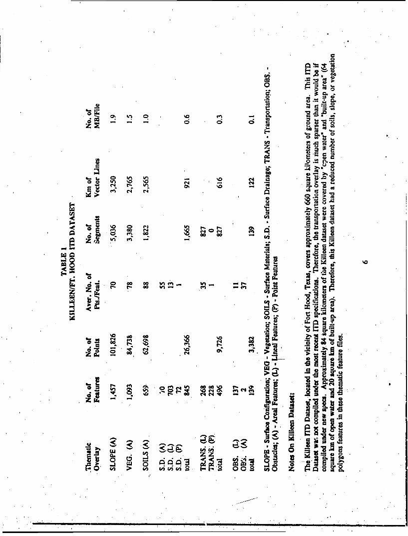
2.4 Data Density
Software was developed by ETL in orde. to be able to obtain data density information for lTD. Thissoftware was necessaiy in order to be able to calculate: the total lineal meters of vector data per ITDthemat:c file; and the number of features, segments, and nodes pe*r ITD thematic file.
Data density information was generated for a ITD dataset located aver the 1:50,000 scale Killeen TLMbasemap in, me vicinity of Fort Hood, Texas. The rýsults are listed in Table 1. The greatest number offea't, 2s for this dataset are found on the "full areal coverage' themati: feature flies (slope, vegetation,soils) with an average of over 1,000 polygon fealures per file. This Killeen iTD dataset is notrepresentative of a typical ITD data.vet because it has a sparse road/railroad network and drainage pattern(low number o1f features, segments, and points.)
FurttJ. •r DCAC investigations are required in order to determine what the data density is for an averageITD cell
2.5 Minimum Polygon Size
Minimum polygon sizes in ground dLqmce were calculated in order to provide further information aboutthe maximum potential data density for rlD's soil, slope, vege',ation, and surface drainage thematicfeature files. For an ITD Surface Drainage feature file the minrimumn polygon size is defined to be 1 mmby 2 mm at map scale.[6] This equates to a ground size of approxi~mately 50 m by 100 m. This meansthat theoretically, there is a maximum potential number of 132,000 polygons for a Surface Drainagefeature file.
For all other ITD themaic files (Vegetation, Slope, Soils, and Tranrponation, and Obstacles) theminimum polygon size is 4 mm by 5 mm (or equivalent area) at map scale. This equates toapproximately 200 m by 250 m on the grrund (or roughly a 50,000 square meter area.)[6]Consequently, for vegetation, soils, and slope there is an upper limit of approximately 13,200 polygonsper thematic feature filo.
These maximum polygon counts for lTD fenture files were calculated using the physical dimensionm ofthe reference basemap. In reality, the polygon counts for any of these thematic featuro files will bemuch lower than these maximum iimits. Nevertheless, this informat;on is useful as a comparison to thepolygon counts for the KiMleen ITDMthematic feature files.
.5
1-1 -o N
a ci
%0 c) C
000 0 00 %nen-- (4 t- 00 W) 40
C14)
>
020
000
vi0v a .-a(4I 0%

2.6 Storage
DCAC was able to obtain information pertaining to lTD's storage requirements by developing softwarewhich could determine the file size for the six ITD thematic files on a 9-track tape. Storage inforrationwas generated for the six Killeen ITD files and the accompanying DTED. The storage requirements foýeach thematic feature file are listed in Table 1. The size of the six Killeen thematic feature files totals5.4 Megabytes (MB). Th,- Size of the DTED Level I cell for Killeen is approximately 3 MB.
The Killeen ITD, as previously mentioned, is sparser than typical lTD. Hence this datasec's thematicfeature files (vector format) have a lower than average storage requirement. Initial estimates for fTDstorage range from 6 to 10 MB. (Typically, the size of vector data files will vary with the numbe, ofpoints used to digitize a feature and the density of features per feature file.)
DCAC personnel must examine a larger sampling of ITD cells in order to more precisely identify therange of files sizes for ITD.
All DTED Level 1 cells (raster format) from 0 degrees to 50 degrees latitude will have th,- szae storagerequirement of approximately 3 MB. At these .4,i~udes, all DTED Level 1 cells have a matri,, of 1201posts by 1201 posts with 3 arcseconds post spacing (or roughly 1OOM post spacing.) At latitudes greaterthan 50 degrees, the size of the matrix is d:creased resulting in smaller storage requirement.
The size of the DTED Level I matrix and consequently the storage requirement could be substantiallyreduced. For example, the DTED provided for the Killeen ITD covers a 1 degree by 1 degree area,whereas the Killeen ITD feature files covers a 15 minute by 15 minute area. Therefore, the size of thedigital elevation matrix, required to cover the Killeen ITD geographically could be reduced by a factor ofsixteen from the original DTED Level 1 file.
2.7 Format and Coding Scheme
2.7.1 ITD Format. lTD is produced in Standard Linear Format (SLF) using the 17 November 1988version of this format. SLF is a DMA digital cartographic feature data exchange format which uses azero-overlap chain-node format for representing the spatial position of cartographic features. In a chain-node format, features are composed of digitized segments (chains of coordinate pairs..) A common,boundary between two features is represented by only one shared segment, thus assuring that thesefeatures are precisely abutted. SLF stores the segments and provides the linkage (pointers) toconcatenate them into features.[21
2.7.2 SSDB Formats. The SSDB supports two formats for storing feature data within its Culture DataFiles (CDF). One format is a chain-node structure which permits sharing of nodes and line segmentsamong features. (According to the Project 2851 contractor, an internal SSDB chain-node format doesexist but has not been implemented.) The other SSDB format for storing feature data is & polygonalformat. As stated in SSDB documentation, this format "employs a polygon prioritization layeringapproach based on visual priority, similar to the approach used in the Digital Landmass System (DLMS)[DFAD's format], to handle stacked or overlapping features." No sharing of nodes and line segments ispermitted for this format.
2.7.3 ITD Coding Scheme. 1TD feature/attribute information is encoded using the Defense MappingAgency Feature File (DMAFF) EOF 15034, Appendix 10.35, December 1983 coding scheme.1lJ Thiscoding scheme uses a hierarchical approach to encode the feature information. Each digitized feature has
7

associated with it a feature code. Each feature will also have one or more attributes associated with it,each containing a unique attribute value. The DMAFF coding scheme lists features using a 'ive-digitalphanumeric (a/n) code, and attributes of features are listed by a three-digit a/n code. An attribute'svalue is defined by a numeric value which may range from 0 - 99998 for some attribute codes.
An example of a DMAFF Feature Code is 'iir030" which defines a road feature. A road feature mryhave associated with it as many as 25 metric and descriptive attributes iu the DMAFF coding scheme.Ther. attr.butes define such things as: road Wid1b (WDD) ranging in value from 0 to 500 decimeters;Road Surface Tye (RST) with attribute values of 0 = unknown, I = hard/unpaved. 2 = loose/unpaved, 3 = loose/light, and 4 = corduroy; and Accur•a (ACC)'with attribute values of 0 =
unknown, 1 = accurate, 2 = approximate, 3 = doubtful, and 4 = juxtaposition.
2.7.4 SSDB Coding Scheme. The SSDB uses a feature coding scheme, called Feature Descriptor Code(FDC), which is similar to the five-character, hierarchical, alphanumeric feature ,odes established forDMA's Feature Attriite Coding System (FACS). FDC uses the FACS codes for features from theDecember 1988 version (E20-013) of DMA's Feature/Attribute Glossary. In addition, the FDC hasincorporated Project 2851 specific feature categories not available in the FACS glossary. Every featurerecord has a FDC field (which identifies the type of feature), fields which defined conimon attributes,and a field for FACS attribute codes.141
2.7.5 Conversion of rrD into SSDB Format. The conversion of ITD in SLF to the SSDB chain-nodeformat should require only a remapping of lTD records into the SSDB record format.
2.7.6 Conversion of rrD into the FDC Coding Scheme. Mapping 1TD feature information from theDMAFF coding scheme to the SSDB's coding scheme will require the generation of a conversion look-up table. rl"D DMAFF feature codes will map directly into an appropriate FDC code. Also, every ITDDMAFF attribute should map into either the common attribute field or iato the SSDB FACS attributefield. Since the SSDB has the flexibility to add an indefinite number of new attribute fields withouthaving to modify the database structure, lTD's attribute information should be easily inserted into theSSDB. Adding new FDC codes or modifying existing FDC feature codes may be necessary toincotporate vegetation and surface material features correctly into the SSDB. For example, the FDCdoes not contain the following FACS codes: 5EOlO LAND USE/LAND-COVER (majority of features inthe Vegetation datafile), and 4A030 SURFICIAL MATERIALS (majority of features in the SurfaceMaterials datafile).
2.8 Structure
The SSDB record structure appears-to be similar to SLF structure. The structure of both SLF and SSDBhas records containing attribute information, pointers from features to segments, FACS-like codes, list ofsegments, backpointers froir segments to features, segment number, and a directed coordinate pair list.The structure of each differs but the information from rld should easily map into the SSDB structure.
2.9 Datum and Cell Size
Both rrD and SSDB cells are referenced to the WGS 84 horizontal datum; the vertical datum is MeanSea Level. Both, rD and SSDB feature data are positionally defined by lttude and longitude in two-dimensional space.
. , p . ,.8

As previously mentionad, ITD cell size is determined by the dimensions of the 1:50,000 scale TLM fromwhich the ITD cell is based. A TLM varies in size depending on the map series, the latitude of the mapsheet, and other ano:malies. The majority of ITD produced to date are 15 minutes by.15 minutes or 12minutes by 20 minutes. Similarly, PITD cell size is defined by the dimensions of the 1:250,000 scaleJOG from which ,ae PITD cell is based. JOGs vary latitudinally from on, degree by one degree nearthe equator to one degree by five degrees near the poles cells. The cell size for the PITD created overthe Middle East is one degree by one degree 30 minutes.
The SSDB is managed in one degree by one degree units called cells. These cells are subdivided intomanuscripts which are separate data files representing different forms of data and levels of detail(LOD). One of these SSDB manuscripts, called the culture data file, is where a cell of 1TD informationwill map. The one degree by one degree DC ED file that accompanies ITD wil! map directly into theSSDB terrain mtaiiscript which is the same size.
2.10 ITD Area Coverage
Limited coverage of ITD is available for CONUS, Germany, Korea; and Saudi Arabia. PITD isavailable in limited coverage over Southwest Asia. Production of ]TD started in 1989. To date therehave been 160 cells of lTD produced over Germany, the Middle East, Korea, and the U.S. In addition,24 cells of PITD have been produced over southwest Asia and the Middle East.
3.0 CONCLUSION
lTD is a "data rich" Digital Topographic Data product containing detailed terrain information. Thisinformation is valuable to the Army simulator rommunity. Based on some rough estimates, ITD seemsto best fit into the SSDB 30m LOD. The coding schemes and format of ITD is similar to that used inthe SSDB. Consi.quently, a successful mapping of ITD into Project 2851's SSDB should not be difficultnor should a lengthy effort be required to create an lTD input program.
DCAC advocates having an ITD input capability to Project 2851's SSDB which would allow, for theincorporation of the entire information content of 1TD into the SSDB. lTD is a readily availablestandard product which will satisfy in part the Army's requirements for digital topOgraphic data. Thoughthe current area coverage for ITD is limited, production of this standard DMA product is planned wellirt'o the late ,990s.
9

REFERENCES
1. DRAFT Defense Mapping Agency Feature File (DMAFFl. Second Edition. Defense MappingAgency Aerospace Center; St. Louis, Missouri; August 1987.
2. Digital Production System F:andard Linear Format (SLF) fbr Digital Cartographic Feature Data.DPS-SLF-A; 17 Novenher 1988.
3. Memorandum of Agreement: "MOA Setting Forth Two-Party Agreements Relating to ETL Supportof PM TRADE Initiatives in Mapping, Charting, and Geodesy (MC&G) Arena". Army MaterielCommand's Project Manager for Training Devices; Orlando, Florida; 20 April 1990.
4. DRAFT Data Base Design Document (DBDD) Standard Simulator Data Base (SSDB). CDRL 1033;Planning Research Corporation; McLean, Virginia; August 1989.
5. MC&G Product Accuracy. Obsolescence. and Maintenance. DMS No. ST039; Defense MappingSchool; Fort Belvoir, Virginia; September 1986.
6. 1A-AFT Militay.. Specificatior -'nr Interim Terrain Data (ITD) Scales l:50M00 & 1:250.000. MIL-I-89014; Defense Mapping Agency Headquarters; Fairfax, Virginia; 12 March 1990.
10

APPENDIX
Surface Materials Thematic Fileground surface (including soil category)rock outcrop (& rock strata, rock formation)snow field (& ice fields, ice caps)
Surface Configuration Thematic Fileslope (% slope gradient category)
Vezetation Thematic Filebamboo (& wildcane)brushland (& shrub, scrub)cropland (cultivated)grassland (& pasture, meadow)marsh (& bog)orchard (& plantation)swamp (& mangrove)trees (forest area)vineyard (& hops)wetlands Qand subject to inundation)
Fetures that exist on Multiple Thematic Filesbuilt-up areaford (off-route & on-route)miscellaneous graphic featureopen water (except inland)void collection area
Surface Drainage Thema_91tc~jaqueductcanal (& channelized stream, drainage ditch)damfloating bridge (& raft site)gorgeislandlockriver (& stream)
Transoortation Thematic Filebridgebridge spancart trackconstrictiondrop gate (& drop gate road.)ferry crossingrailroad rackrailroad passing (track)railroad siding (track)
\I

APPENDIX (Continued)
Transoortation Thematic File (cont'd)railroad yardroadroad radius curvaturerunway (airfield)tunnel (& tunnel entrance/exit)
Obstacles Thematic Filecut (road fill, railroad cut)depressiondike (volcanic dike)dragon teethembankmentescarpment (& bluff, cliff)fill (road fill, railroad fill)hedgerowmoatpipelinewall (& fence)ramp (crossing ramp)
Note: The surface materials, configuration, and vegetation thematic files are used as input to the Cross-Country Mobility Model. These' three thematic files are full area coverage datasets.
12

IDAT C
o7000