ethernet reference manual, enet-rm002d-en-p · cisco systems®. the design guide is built on, and...
TRANSCRIPT

Ethernet
Reference ManualOriginal Instructions

Important User Information
Read this document and the documents listed in the additional resources section about installation, configuration, and operation of this equipment before you install, configure, operate, or maintain this product. Users are required to familiarize themselves with installation and wiring instructions in addition to requirements of all applicable codes, laws, and standards.
Activities including installation, adjustments, putting into service, use, assembly, disassembly, and maintenance are required to be carried out by suitably trained personnel in accordance with applicable code of practice.
If this equipment is used in a manner not specified by the manufacturer, the protection provided by the equipment may be impaired.
In no event will Rockwell Automation, Inc. be responsible or liable for indirect or consequential damages resulting from the use or application of this equipment.
The examples and diagrams in this manual are included solely for illustrative purposes. Because of the many variables and requirements associated with any particular installation, Rockwell Automation, Inc. cannot assume responsibility or liability for actual use based on the examples and diagrams.
No patent liability is assumed by Rockwell Automation, Inc. with respect to use of information, circuits, equipment, or software described in this manual.
Reproduction of the contents of this manual, in whole or in part, without written permission of Rockwell Automation, Inc., is prohibited.
Throughout this manual, when necessary, we use notes to make you aware of safety considerations.
Labels may also be on or inside the equipment to provide specific precautions.
WARNING: Identifies information about practices or circumstances that can cause an explosion in a hazardous environment, which may lead to personal injury or death, property damage, or economic loss.
ATTENTION: Identifies information about practices or circumstances that can lead to personal injury or death, property damage, or economic loss. Attentions help you identify a hazard, avoid a hazard, and recognize the consequence.
IMPORTANT Identifies information that is critical for successful application and understanding of the product.
SHOCK HAZARD: Labels may be on or inside the equipment, for example, a drive or motor, to alert people that dangerous voltage may be present.
BURN HAZARD: Labels may be on or inside the equipment, for example, a drive or motor, to alert people that surfaces may reach dangerous temperatures.
ARC FLASH HAZARD: Labels may be on or inside the equipment, for example, a motor control center, to alert people to potential Arc Flash. Arc Flash will cause severe injury or death. Wear proper Personal Protective Equipment (PPE). Follow ALL Regulatory requirements for safe work practices and for Personal Protective Equipment (PPE).

Table of Contents
Preface . . . . . . . . . . . . . . . . . . . . . . . . . . . . . . . . . . . . . . . . . . . . . . . . . . . . . . . .7Summary of Changes . . . . . . . . . . . . . . . . . . . . . . . . . . . . . . . . . . . . . . . . . . . 7Additional Resources . . . . . . . . . . . . . . . . . . . . . . . . . . . . . . . . . . . . . . . . . . . 8
Chapter 1Ethernet Overview Ethernet Protocols . . . . . . . . . . . . . . . . . . . . . . . . . . . . . . . . . . . . . . . . . . . . . 9
MAC Addresses. . . . . . . . . . . . . . . . . . . . . . . . . . . . . . . . . . . . . . . . . . . . . . . 10IP Addresses . . . . . . . . . . . . . . . . . . . . . . . . . . . . . . . . . . . . . . . . . . . . . . . . . . 10
IP Address Assignment Methods. . . . . . . . . . . . . . . . . . . . . . . . . . . . 10Subnet Masks . . . . . . . . . . . . . . . . . . . . . . . . . . . . . . . . . . . . . . . . . . . . . . . . . 12Gateways . . . . . . . . . . . . . . . . . . . . . . . . . . . . . . . . . . . . . . . . . . . . . . . . . . . . . 13Communication Protocols . . . . . . . . . . . . . . . . . . . . . . . . . . . . . . . . . . . . . 14
Address Resolution Protocol (ARP). . . . . . . . . . . . . . . . . . . . . . . . . 14Domain Name System (DNS) . . . . . . . . . . . . . . . . . . . . . . . . . . . . . . 15
Transmission Packets . . . . . . . . . . . . . . . . . . . . . . . . . . . . . . . . . . . . . . . . . . 16Multicast . . . . . . . . . . . . . . . . . . . . . . . . . . . . . . . . . . . . . . . . . . . . . . . . . 17Multicast Address Limit . . . . . . . . . . . . . . . . . . . . . . . . . . . . . . . . . . . 18
Resiliency. . . . . . . . . . . . . . . . . . . . . . . . . . . . . . . . . . . . . . . . . . . . . . . . . . . . . 19Time Calculations in a Logix5000 System . . . . . . . . . . . . . . . . . . . 19Resiliency Protocols . . . . . . . . . . . . . . . . . . . . . . . . . . . . . . . . . . . . . . . 19
Chapter 2Ethernet Infrastructure Components
Topologies. . . . . . . . . . . . . . . . . . . . . . . . . . . . . . . . . . . . . . . . . . . . . . . . . . . . 22Media . . . . . . . . . . . . . . . . . . . . . . . . . . . . . . . . . . . . . . . . . . . . . . . . . . . . . . . . 24Media Converters . . . . . . . . . . . . . . . . . . . . . . . . . . . . . . . . . . . . . . . . . . . . . 25Bridges . . . . . . . . . . . . . . . . . . . . . . . . . . . . . . . . . . . . . . . . . . . . . . . . . . . . . . . 25Routers and Gateways . . . . . . . . . . . . . . . . . . . . . . . . . . . . . . . . . . . . . . . . . 26Switches . . . . . . . . . . . . . . . . . . . . . . . . . . . . . . . . . . . . . . . . . . . . . . . . . . . . . . 27
Unmanaged versus Managed Switches . . . . . . . . . . . . . . . . . . . . . . . 27Autonegotiation. . . . . . . . . . . . . . . . . . . . . . . . . . . . . . . . . . . . . . . . . . . 28Full-duplex Mode . . . . . . . . . . . . . . . . . . . . . . . . . . . . . . . . . . . . . . . . . 28
Chapter 3Ethernet Infrastructure Features Authentication, Authorization, and Accounting (AAA) . . . . . . . . . . 32
Authentication . . . . . . . . . . . . . . . . . . . . . . . . . . . . . . . . . . . . . . . . . . . . 32Authorization . . . . . . . . . . . . . . . . . . . . . . . . . . . . . . . . . . . . . . . . . . . . . 32Accounting . . . . . . . . . . . . . . . . . . . . . . . . . . . . . . . . . . . . . . . . . . . . . . . 33Server Protocols . . . . . . . . . . . . . . . . . . . . . . . . . . . . . . . . . . . . . . . . . . . 33Server Groups and Deadtimes . . . . . . . . . . . . . . . . . . . . . . . . . . . . . . 34Method Lists . . . . . . . . . . . . . . . . . . . . . . . . . . . . . . . . . . . . . . . . . . . . . . 34
Access Control Lists (ACLs) . . . . . . . . . . . . . . . . . . . . . . . . . . . . . . . . . . . 35Access Control Entries (ACEs) . . . . . . . . . . . . . . . . . . . . . . . . . . . . . 35
Certificate Authority (CA) Trustpoints. . . . . . . . . . . . . . . . . . . . . . . . . 36Device Level Ring (DLR) . . . . . . . . . . . . . . . . . . . . . . . . . . . . . . . . . . . . . . 36
Rockwell Automation Publication ENET-RM002D-EN-P - December 2019 3

Table of Contents
Dynamic Host Configuration Protocol (DHCP) . . . . . . . . . . . . . . . . 37IP Address Pools . . . . . . . . . . . . . . . . . . . . . . . . . . . . . . . . . . . . . . . . . . 37DHCP Snooping . . . . . . . . . . . . . . . . . . . . . . . . . . . . . . . . . . . . . . . . . . 37DHCP Persistence . . . . . . . . . . . . . . . . . . . . . . . . . . . . . . . . . . . . . . . . 37Device Level Ring (DLR) DHCP . . . . . . . . . . . . . . . . . . . . . . . . . . . 37
Flex Links . . . . . . . . . . . . . . . . . . . . . . . . . . . . . . . . . . . . . . . . . . . . . . . . . . . . 38Internet Group Management Protocol (IGMP). . . . . . . . . . . . . . . . . . 39
IGMP Snooping with Querier . . . . . . . . . . . . . . . . . . . . . . . . . . . . . . 39Multicast Group Limits . . . . . . . . . . . . . . . . . . . . . . . . . . . . . . . . . . . . 40
Logical Interfaces. . . . . . . . . . . . . . . . . . . . . . . . . . . . . . . . . . . . . . . . . . . . . . 40Port Channels or EtherChannels . . . . . . . . . . . . . . . . . . . . . . . . . . . 40Loopback Interfaces . . . . . . . . . . . . . . . . . . . . . . . . . . . . . . . . . . . . . . . 42Switch Virtual Interfaces (SVIs) . . . . . . . . . . . . . . . . . . . . . . . . . . . . 42
Network Address Translation (NAT). . . . . . . . . . . . . . . . . . . . . . . . . . . 42Allen-Bradley Products That Support NAT . . . . . . . . . . . . . . . . . 43
Network Time Protocol (NTP) . . . . . . . . . . . . . . . . . . . . . . . . . . . . . . . . 43Parallel Redundancy Protocol (PRP) . . . . . . . . . . . . . . . . . . . . . . . . . . . . 44Port Security . . . . . . . . . . . . . . . . . . . . . . . . . . . . . . . . . . . . . . . . . . . . . . . . . . 44
Dynamic Secure MAC Address (MAC ID) . . . . . . . . . . . . . . . . . . 44Static Secure MAC Address (MAC ID) . . . . . . . . . . . . . . . . . . . . . 44Security Violations . . . . . . . . . . . . . . . . . . . . . . . . . . . . . . . . . . . . . . . . 45
Power over Ethernet (PoE). . . . . . . . . . . . . . . . . . . . . . . . . . . . . . . . . . . . . 46Precision Time Protocol (PTP)/CIP Sync. . . . . . . . . . . . . . . . . . . . . . . 47
PTP Clocks . . . . . . . . . . . . . . . . . . . . . . . . . . . . . . . . . . . . . . . . . . . . . . . 47Ethernet Switches and Delays. . . . . . . . . . . . . . . . . . . . . . . . . . . . . . . 48Message-Based Synchronization . . . . . . . . . . . . . . . . . . . . . . . . . . . . 48Best Master Clock Algorithm. . . . . . . . . . . . . . . . . . . . . . . . . . . . . . . 50PTP Clock Modes . . . . . . . . . . . . . . . . . . . . . . . . . . . . . . . . . . . . . . . . . 50
Quality of Service (QoS) . . . . . . . . . . . . . . . . . . . . . . . . . . . . . . . . . . . . . . . 51QoS Guidelines . . . . . . . . . . . . . . . . . . . . . . . . . . . . . . . . . . . . . . . . . . . 52
Resilient Ethernet Protocol (REP) . . . . . . . . . . . . . . . . . . . . . . . . . . . . . . 52REP Segments. . . . . . . . . . . . . . . . . . . . . . . . . . . . . . . . . . . . . . . . . . . . . 53REP Limitations. . . . . . . . . . . . . . . . . . . . . . . . . . . . . . . . . . . . . . . . . . . 55Link Integrity . . . . . . . . . . . . . . . . . . . . . . . . . . . . . . . . . . . . . . . . . . . . . 55Fast Convergence. . . . . . . . . . . . . . . . . . . . . . . . . . . . . . . . . . . . . . . . . . 56VLAN Load Balancing. . . . . . . . . . . . . . . . . . . . . . . . . . . . . . . . . . . . . 56Spanning Tree Interaction . . . . . . . . . . . . . . . . . . . . . . . . . . . . . . . . . 58REP Ports. . . . . . . . . . . . . . . . . . . . . . . . . . . . . . . . . . . . . . . . . . . . . . . . . 58Requirements and Restrictions . . . . . . . . . . . . . . . . . . . . . . . . . . . . . 59
Simple Network Management Protocol (SNMP) . . . . . . . . . . . . . . . . 61Spanning Tree Protocol (STP) . . . . . . . . . . . . . . . . . . . . . . . . . . . . . . . . . 62Switched Port Analyzer (SPAN) or Port Mirroring . . . . . . . . . . . . . . 63Virtual Local Area Networks (VLANs) . . . . . . . . . . . . . . . . . . . . . . . . . 64
VLAN Trunking . . . . . . . . . . . . . . . . . . . . . . . . . . . . . . . . . . . . . . . . . . 66VLANs and Segmentation Guidelines . . . . . . . . . . . . . . . . . . . . . . . 67
VLAN Trunking Protocol (VTP) . . . . . . . . . . . . . . . . . . . . . . . . . . . . . . 67
4 Rockwell Automation Publication ENET-RM002D-EN-P - December 2019

Table of Contents
Appendix AEtherNet/IP Protocol Common Industrial Protocol (CIP) . . . . . . . . . . . . . . . . . . . . . . . . . . . . 70
Connections . . . . . . . . . . . . . . . . . . . . . . . . . . . . . . . . . . . . . . . . . . . . . . . . . . 70Terminology . . . . . . . . . . . . . . . . . . . . . . . . . . . . . . . . . . . . . . . . . . . . . . 72TCP Connections . . . . . . . . . . . . . . . . . . . . . . . . . . . . . . . . . . . . . . . . . 73CIP Connections. . . . . . . . . . . . . . . . . . . . . . . . . . . . . . . . . . . . . . . . . . 73CIP Connection Message Types . . . . . . . . . . . . . . . . . . . . . . . . . . . . 74CIP Connection Types . . . . . . . . . . . . . . . . . . . . . . . . . . . . . . . . . . . . 74
Packets Rate Capacity . . . . . . . . . . . . . . . . . . . . . . . . . . . . . . . . . . . . . . . . . 75Messaging . . . . . . . . . . . . . . . . . . . . . . . . . . . . . . . . . . . . . . . . . . . . . . . . . . . . 76
Implicit Messages . . . . . . . . . . . . . . . . . . . . . . . . . . . . . . . . . . . . . . . . . . 76Explicit Messages . . . . . . . . . . . . . . . . . . . . . . . . . . . . . . . . . . . . . . . . . . 77
Index . . . . . . . . . . . . . . . . . . . . . . . . . . . . . . . . . . . . . . . . . . . . . . . . . . . . . . . .79
Rockwell Automation Publication ENET-RM002D-EN-P - December 2019 5

Table of Contents
Notes:
6 Rockwell Automation Publication ENET-RM002D-EN-P - December 2019

Preface
Rockwell Automation uses open network technology for plant-wide integration. These open networks share a universal set of communication services. As a result, information can be communicated seamlessly throughout the plant and to and from the Internet for e-business applications.
This publication describes features and tools to help you configure your network.
Summary of Changes
Comparison EtherNet/IP Network ControlNet Network DeviceNet Network
Function Converges the plant network with the enterprise network providing configuration, data collection, and control on one high-speed network
Supports transmission of time critical data between PLC processors and I/O devices
Connects low-level devices directly to plant-floor controllers without the use of I/O modules
Typical devices networked • Mainframe computers• Programmable controllers• Robots• HMI• Personal computers• Servers• I/O• Drives• Process instruments
• Programmable controllers• I/O chassis• HMIs• Personal computers• Drives• Robots
• Sensors• Motor starters• Drives• Personal computers• Push buttons• Low-end HMIs• Barcode readers• PLC processors• Valve manifolds
Data repetition Large packets, data sent regularly Medium-size packets; data transmissions are deterministic and repeatable
Small packets; data sent as needed
Number of nodes, max No limit 99 nodes 64 total nodes
Data transfer rate 10 Mbps, 100 Mbps, 1 Gbps, or 10 Gbps 5 Mbps 500 Kbps, 250 Kbps, or 125 Kbps
Typical use Plant-wide architectureHigh-speed applications
Redundant applicationsScheduled communication
Supply power and connectivity to low-level devices
Topic Page
Added features to Infrastructure Features chapter 31
Moved EtherNet/IP Network Specifications to Ethernet/IP Network Devices User Manual, publication ENET-UM006
Rockwell Automation Publication ENET-RM002D-EN-P - December 2019 7

Preface
Additional Resources These documents contain additional information concerning related products from Rockwell Automation.
You can view or download publications athttp://www.rockwellautomation.com/global/literature-library/overview.page.
Table 1 - ODVA Resources
Resource Description
http://www.odva.org/ Accesses the Open DeviceNet™ Vendors Association (ODVA) website.
Ethernet Media Planning and Installation Manual, ODVA publicationhttp://www.odva.org/Portals/0/Library/Publications_Numbered/PUB00148R0_EtherNetIP_Media_Planning_and_Installation_Manual.pdf
Describes the required media components and how to plan for, install, verify, troubleshoot, and certify an Ethernet network.
Network Infrastructure for EtherNet/IP: Introduction and Considerations, ODVA publicationhttp://www.odva.org/Portals/0/Library/Publications_Numbered/PUB00035R0_Infrastructure_Guide.pdf
Provides an overview of the technologies that are used in EtherNet/IP™ networks and provides guidelines to deploy infrastructure devices in EtherNet/IP networks.
Table 2 - Rockwell Automation Resources
Resource Description
EtherNet/IP Network Devices User Manual, ENET-UM006 Describes how to configure and use EtherNet/IP devices with a Logix 5000™ controller and communicate with various devices on the Ethernet network.
Stratix 2500 Lightly Managed Switches User Manual, publication 1783-UM009 Describes how to configure and troubleshoot Stratix® 2500 switches.
Stratix Managed Switches User Manual, publication 1783-UM007 Describes how to configure and troubleshoot Stratix 5400, 5410, 5700, 8000, 8300, and ArmorStratix™ 5700 switches.
Stratix 5800 Ethernet Managed Switches User Manual, publication 1783-UM012 Describes how to configure and troubleshoot Stratix 5800 switches.
EtherNet/IP Parallel Redundancy Protocol Application Technique, ENET-AT006 Describes Parallel Redundancy Protocol (PRP) topologies, configuration considerations, and diagnostic methods.
EtherNet/IP Device Level Ring Application Technique, publication ENET-AT007 Describes Device Level Ring (DLR) topologies, configuration considerations, and diagnostic methods.
EtherNet/IP QuickConnect Application Technique, publication ENET-AT001 Describes EtherNet/IP QuickConnect technology. QuickConnect technology enables EtherNet/IP devices to quickly power up and join an EtherNet/IP network.
EtherNet/IP Socket Interface Application Technique, publication ENET-AT002 Describes the socket interface that is used to program MSG instructions to communicate between a Logix5000 controller via an EtherNet/IP module and Ethernet devices that do not support the EtherNet/IP application protocol.
Industrial Automation Wiring and Grounding Guidelines, publication 1770-4.1 Provides general guidelines for installing a Rockwell Automation industrial system.
Product Certifications website: rok.auto/certifications Provides declarations of conformity, certificates, and other certification details.
Table 3 - Cisco and Rockwell Automation Alliance Resources
Resource Description
Converged Plantwide Ethernet (CPwE) Design and Implementation Guide, publication ENET-TD001
Represents a collaborative development effort from Rockwell Automation and Cisco Systems®. The design guide is built on, and adds to, design guidelines from the Cisco Ethernet-to-the-Factory (EttF) solution and the Rockwell Automation® Integrated Architecture™. The design guide focuses on the manufacturing industry.
Deploying Device Level Ring within a Converged Plantwide Ethernet Architecture, publication ENET-TD015
Provides design recommendations for connecting device-level topologies to networks comprised of Layer 2 switches. It also covers the implementation of embedded switch technology within the Converged Plantwide Ethernet (CPwE) Cell/Area zone.
8 Rockwell Automation Publication ENET-RM002D-EN-P - December 2019

Chapter 1
Ethernet Overview
Ethernet Protocols Ethernet refers to wired connectivity and networking technology for devices in a local area network (LAN). International standard IEEE 802.3 defines wired Ethernet standards.
All Ethernet networks support protocols that provide data transfer and network management capability.
Topic Page
Ethernet Protocols 9
MAC Addresses 10
IP Addresses 10
Subnet Masks 12
Gateways 13
Communication Protocols 14
Transmission Packets 16
Resiliency 19
Protocol Description
Common Industrial Protocol (CIP™) CIP applies a common application layer over an Ethernet network by encapsulating messages in TCP/UDP/IP. This common application layer provides interoperability and interchangeability of industrial automation and control modules on an Ethernet network.
Transmission Control Protocol/Internet Protocol (TCP/IP)
TCP/IP is a transport-layer protocol (TCP) and a network-layer protocol (IP) commonly used in business environments for communication within networks and across internetworks. EtherNet/IP™ communication modules use TCP/IP for Explicit Messaging when time is not a critical factor, such as when you upload or download programs.
User Datagram Protocol/Internet Protocol (UDP/IP)
UDP is a simple, message-based protocol that makes no effort to establish dedicated end-to-end connections. With UDP messages, packets cross the network in independent, whole units. UDP is smaller, simpler, and faster than TCP and can operate in unicast, multicast, or broadcast mode. EtherNet/IP communication modules use UDP/IP for real-time I/O messaging.
Rockwell Automation Publication ENET-RM002D-EN-P - December 2019 9

Chapter 1 Ethernet Overview
MAC Addresses All devices on Ethernet communicate by using the MAC address for the device. This address is sometimes referred to as the hardware address or Media Access Controller (MAC) address. The hardware address is a unique, six-byte address, which is embedded in the circuitry of every device on an Ethernet network. Every vendor of Ethernet products obtains their own unique address range.
IP Addresses For a device to communicate on an Ethernet network, you must configure its IP address, gateway address, and subnet mask. The IP address identifies each node on the IP network or system of connected networks. Each node on a network must have a unique IP address. The IP address is 32 bits long and has a network ID part and a host ID part.
Public IP addresses are for computers and devices that are connected to the Internet. Devices on industrial networks are not connected to the Internet, but they communicate with each other over an EtherNet/IP network. These devices use private IP addresses that are not routed on the Internet.
Private IP addresses typically start with 10, 172, or 192 as the first part of the address. Private IP addresses are typically connected to the Internet through a Network Address Translation (NAT) device. For more information about NAT, see page 42.
IP Address Assignment Methods
There are multiple methods to set an IP address:
• Physical methods, such as thumbwheels or push buttons, on some devices
• Software-based methods, such as the Studio 5000® Logix Designer application, Linx-based software, and HMI module interfaces
IP addresses can be either static or dynamic:
• Static IP addresses do not change and survive power cycles.
• Dynamic IP addresses are automatically assigned and can change after a power cycle. Dynamic addresses require support for BOOTP or Dynamic Host Configuration Protocol (DHCP).
Table 4 compares the different IP address assignment methods.
10 Rockwell Automation Publication ENET-RM002D-EN-P - December 2019

Ethernet Overview Chapter 1
Table 4 - IP Address Assignment Methods
Method Description
Static Devices are hard-coded with an IP address.AdvantageSimple to commission and replaceDisadvantageIn large environments, can be burdensome to maintain
Dynamic via BOOTP A BOOTP server assigns devices an IP address.BOOTP technology is a precursor to DHCP.AdvantageSupported by every deviceDisadvantages• Requires technician to configure IP address/MAC address when a device is replaced• Requires a personal computer for commissioning and replacement (unless the device has a physical method to set
the address offline)• Adds complexity and point of failure
Dynamic via DHCP A server assigns IP addresses from a pool.Advantages• Efficient use of IP address range• Can reduce administration work load• A replaced device receives the expected IP addressDisadvantages• More complex to implement and adds a point of failure• Devices get different IP addresses when they restart
DHCP option 82 A server assigns consistent IP addresses from a pool.Advantages• Receives the same IP address each time that one is assigned• Efficient use of IP address range• Can reduce administration work loadDisadvantages• More complex to implement and adds a point of failure• Mixed environments do not always work
DHCP port-based allocation IP addresses are automatically assigned per physical switch port.Advantages• Receives the same IP address each time that one is assigned• Efficient use of IP address range• Eases maintenance and replacement in large environmentsDisadvantageRequires some maintenance and upkeep on a per switch basis
DHCP for ring devices IP addresses are automatically assigned per ring position.Advantages• Efficient use of IP address range• A replaced device receives the expected IP address• Eases maintenance and replacement in Device Level Ring (DLR) topologiesDisadvantage• Requires some maintenance• Devices get different IP addresses when they restart
Rockwell Automation Publication ENET-RM002D-EN-P - December 2019 11

Chapter 1 Ethernet Overview
Subnet Masks A subnet mask is an extension of the IP address scheme. It allows a site to use one net ID for multiple physical networks. Inside a site, the subnet mask is used to redivide the IP address into a custom net ID portion and host ID portion.
A subnet mask determines which of the 32 bits in the IP address are part of the network ID and which are part of the unique node identification.
Take the IP address 128.2.0.1 and add another physical network. Selecting this subnet mask adds two additional net ID bits providing for four physical networks.
11111111 11111111 11111111 00000000 = 255.255.255.0
Two bits of the host ID have been used to extend the net ID. Each unique combination of bits in the part of the host ID where subnet mask bits are 1 specifies another network.
A second network with hosts D and E has been added. Gateway G2 connects network 2.1 with network 2.2. Hosts D and E use gateway G2 to communicate with hosts not on network 2.2. Hosts B and C use gateway G to communicate with hosts not on network 2.1. When B is communicating with D, G (the configured gateway for B) routes the data from B to D through G2.
128.1.0.1
128.2.64.1
128.2.64.3
128.1.0.2Network 1
Network 2.1
128.2.128.1 128.2.128.2
128.2.128.3
128.2.64.4
128.1.0.1
128.2.64.1
128.2.128.1
128.2.64.2
128.2.128.2
128.1.0.2
128.2.64.3
128.2.128.3
A
B C
G
G2
D E
Network 2.2
12 Rockwell Automation Publication ENET-RM002D-EN-P - December 2019

Ethernet Overview Chapter 1
Gateways A gateway connects individual physical networks into a system of networks. When a node must communicate with a node on another network, a gateway transfers the data between the two networks. The following figure shows that gateway G connects Network 1 with Network 2.
When host B with IP address 128.2.0.1 communicates with host C, it knows from the IP address of host C that C is on the same network. In an Ethernet environment, B can then resolve the IP address of host C to a MAC address and communicate with C directly.
When host B communicates with host A, it knows from the IP address of host A that A is on another network because the network IDs differ. To send data to A, B must have the IP address of the gateway that connects the two networks. In this example, the gateway IP address on Network 2 is 128.2.0.3.
The gateway has two IP addresses (192.168.1.1 and 192.168.2.1). Network 1 hosts must use the first IP address, and Network 2 hosts must use the second IP address. To be usable, a gateway IP address of a host must match its own net ID.
Devices with IP address switches use the default gateway address of either 192.168.1.1 or 0.0.0.0. Check your product information to determine which gateway address applies for your device.
Network 1
Network 2
A
B C
G
192.168.1.1
192.168.2.1
128.2.0.2128.2.0.1
128.1.0.1
Rockwell Automation Publication ENET-RM002D-EN-P - December 2019 13

Chapter 1 Ethernet Overview
Communication Protocols Ethernet is a robust technology with many communication protocols working together to provide different services.
Address Resolution Protocol (ARP)
An ARP request is a broadcast message. The purpose of an ARP request is to discover which device has a particular IP address. The device that has that IP address responds to the ARP request. The requesting device then maps the IP address with the MAC address of the responding device and adds the address pair to its ARP cache. The requesting device can now send the message. This protocol enables the network to learn and adapt to changes.
If you replace an EtherNet/IP communication module with a new module, the new module has another MAC ID. The ARP cache entries in other devices are now invalid because the MAC ID that corresponds to the IP address of the module has changed. The invalid cache entry can cause a delay in re-establishing communication with the replacement module. The delay varies depending on the module and the network configuration in use.
When an EtherNet/IP device starts up, it issues a gratuitous ARP that causes other devices to update their ARP caches. This generally results in a quick recovery of communication with the replacement module (less than a minute after connecting to the network).
1756 Controller
1756 Controller with IP Address 130.151.3.2 The 1756 controller must send a
message to 130.151.3.4.
ARP Request for IP Address 130.151.3.4
PowerFlex® Drive with IP Address 130.151.3.4
1734 POINT I/O™
The drive responds to the ARP request.
14 Rockwell Automation Publication ENET-RM002D-EN-P - December 2019

Ethernet Overview Chapter 1
Domain Name System (DNS)
DNS is a name resolution protocol that enables you to identify devices by names rather than IP addresses. For DNS to work, a DNS server is configured to hold a table of names and the associated IP addresses. When a device attempts to send a message to a device with an unknown name, it requests the IP address of the named device from the DNS server.
The DNS server refers to its table and sends back an IP address for the requested name. Once the client device receives the IP address for a name, it stores it in its own table. The device must no longer ask for the IP address every time. The device still sends an ARP request if it must decode the IP address into a hardware address.
DNS Server
What is the IP address for the PowerFlex drive?
1756 ControllerThe controller must send a message to the PowerFlex drive.
1734 POINT I/O
PowerFlex Drive
130.151.3.4
DNS ServerPowerFlex drive has IP address 130.151.3.4.
1756 Controller
1734 POINT I/O
PowerFlex Drive
130.151.3.4
DNS Table
Name IP Address
Controller 130.151.3.2
PowerFlex Drive 130.151.3.4
POINT I/O 130.151.3.6
Rockwell Automation Publication ENET-RM002D-EN-P - December 2019 15

Chapter 1 Ethernet Overview
Transmission Packets Data is transmitted over an Ethernet network in packets. There are transmission methods for transporting data on the network.
Figure 1 - Transmission Methods
Packet Type Destination Description
Unicast One node Unicast connections are point-to-point transmissions between a source node and destination node on the network. A transmission is sent to one destination.
Multicast Multiple nodes simultaneously
Multicast connections deliver information from one sender to multiple receivers simultaneously.Copies of one transmission are passed to a selected subset of possible destinations.
Broadcast All nodes Broadcast connections transmit information to every device on the network.A transmission is delivered to all hosts on the network.
16 Rockwell Automation Publication ENET-RM002D-EN-P - December 2019

Ethernet Overview Chapter 1
Limit the amount of broadcast and multicast traffic on the supervisory control network:
• Eliminating unwanted traffic reduces the load on devices, switches, and the network.
• Eliminating unnecessary incoming broadcast traffic also minimizes network load.
It is important to segregate traffic in the plant network from the enterprise network.
Multicast
With multicast, one or more senders and one or more recipients participate in data transmission. In this sense, multicast is a hybrid of unicast (one-to-one) and broadcast (one-to-all).
Use multicast in these situations:• Redundancy applications• Communication with multiple destinations
Multicast is more efficient than sending multiple, unicast streams to multiple nodes.
• Video streaming
I/O devices generally produce at a fast rate, such as 10 ms. The fast rate makes it easy to flood the network with multicast traffic. Each end device then must spend time deciding whether to discard numerous multicast frames. If there are many I/O devices, they can use up a significant part of the CPU time of a router.
To support the separation of traffic between plant level and enterprise networks, we recommend the following:
• Minimize device load due to unwanted IP multicast traffic.• Minimize switch load due to unwanted IP multicast traffic.• Minimize network load due to unwanted incoming IP multicast or
broadcast traffic.• Block IP multicast traffic that is generated within the EtherNet/IP
subnet from propagating onto the enterprise network.• Implement standard network troubleshooting tools.
For more information, see Virtual Local Area Networks (VLANs) on page 64 and Internet Group Management Protocol (IGMP) on page 39.
Rockwell Automation Publication ENET-RM002D-EN-P - December 2019 17

Chapter 1 Ethernet Overview
Multicast Address Limit
Networks have multicast address limits. The limit for a network depends on the switch infrastructure and the address limit of individual devices. For individual device limits, see the user manual for the device.
The multicast address limit is independent of the connection limit for a device. Not all connections require a multicast address. With produced and consumed tags, one produced tag requires one multicast address, but it also requires one connection for each consumer. If there are multiple consumers, the one multicast address must use multiple connections.
EXAMPLE An Ethernet adapter that produces data uses a unique multicast address for each I/O connection.
EXAMPLE A Logix controller that produces tags uses a unique multicast address for each produced tag.
18 Rockwell Automation Publication ENET-RM002D-EN-P - December 2019

Ethernet Overview Chapter 1
Resiliency A resiliency protocol maintains parallel links for redundancy while avoiding a loop. Network convergence time is a measure of how long it takes to detect a fault, find an alternate path, and recover from the fault:
• During the network convergence time, the network drops some portion of the traffic because interconnectivity does not exist.
• Communication drops if the convergence time is longer than the Logix connection timeout.
Time Calculations in a Logix5000 System
Network convergence must occur before the following communication methods are impacted and the control network is interrupted:
• Logix message instruction (MSG) timeout (explicit, CIP Class 3)
• I/O connection timeout (implicit, CIP Class 1), 4 x RPI, 100 ms minimum
• Logix Producer/Consumer connection timeout (implicit, CIP Class 1), 4 x RPI, 100 ms minimum
• Safety I/O connection timeout (implicit, CIP Class 1), 4 x RPI (default)
Resiliency Protocols
Resiliency Protocol Mixed Vendor Ring Redundant Star Network Convergence
< 250 ms < 70 ms < 3 ms
STP X X X X
RSTP X X X X
MSTP X X X X
PVST+ X X X
REP X X
Port Channels/EtherChannels
X X X
Flex Links X X X
DLR X X X
Rockwell Automation Publication ENET-RM002D-EN-P - December 2019 19

Chapter 1 Ethernet Overview
Notes:
20 Rockwell Automation Publication ENET-RM002D-EN-P - December 2019

Chapter 2
Ethernet Infrastructure Components
The topology and cable layout of the Ethernet network is part of the physical layer. Ethernet systems require various infrastructure components to connect individual network segments.
Topic Page
Topologies 22
Media 24
Media Converters 25
Bridges 25
Routers and Gateways 26
Switches 27
Rockwell Automation Publication ENET-RM002D-EN-P - December 2019 21

Chapter 2 Ethernet Infrastructure Components
Topologies Ethernet networks are laid out in point-to-point configurations with one or more cables for each device. Ethernet networks have active infrastructures that rely on switches. You can design a network with individual switch devices and devices with embedded switch technology.
Additional topologies are available for switches and Ethernet devices that support Device Level Ring technology. For more information about DLR, refer to the Device Level Ring Application Technique, publication ENET-AT007.
Table 5 - Topologies with an Individual Switch
Topology Description
Star The most common EtherNet/IP™ network topology is a star, where end devices are connected and communicate with each other via a switch. In a star topology, nodes are typically grouped closely together.
Advantages• Easy to design, configure, and implement• Direct path between the infrastructure device
and the end device• Remove and add devices without affecting the
rest of the network• Increase port capacity on the switch to add more
devices• Centralization can ease troubleshooting, because
the switch sees the activities of all connected devices
Disadvantages• Loss of network service if there is a connection
failure (no resiliency)• Centralized switch is a single point of failure
Ring—switch based A ring network is a single-fault tolerant ring network that is intended for the interconnection of devices.
Advantages• Can survive one point of failure or a device being
powered down on the ring.• Simplified cabling• Can cover long distances with copper or fiber
connections between each link• Fast convergence times with DLR-capable
switches
Disadvantages• Additional configuration complexity• Longer convergence times without DLR-
capable switches• Variable number of hops can make
performance difficult to predict
Linear—switch based A linear network is a collection of devices that are daisy-chained together.A linear topology works best for a limited number of nodes.
Advantages• Easy to design, configure, and implement• Requires minimal cables• Can cover long distances with copper or fiber
connections between each link
Disadvantages• Loss of network service if there is a connection
failure (no resiliency)• Creates the potential for bottlenecks• Variable number of hops can make
performance difficult to predict• Powering down a device or the failure of a
device in the center of the network affects connectivity between any of the devices on either side
• Each link in the chain represents network delay
Redundant star In a redundant star topology, every Layer 2 access switch has dual connections to a Layer 3 distribution switch. Devices are connected to the Layer 2 switches.
Advantages• Resiliency from multiple connection failures• Faster convergence to connection loss• Consistent number of hops provide predictable
and consistent performance• Fewer bottlenecks
Disadvantages• Additional wiring and ports required• Additional configuration complexity
Switch
D D D
D D
Switch
Switch
SwitchSwitchD
D
D
D
D D
Switch
D D
Switch
D D
Switch
D D
Layer 3 Layer 3
Layer 2
D D
Layer 2
D D
22 Rockwell Automation Publication ENET-RM002D-EN-P - December 2019
Ethernet Infrastructure Components Chapter 2
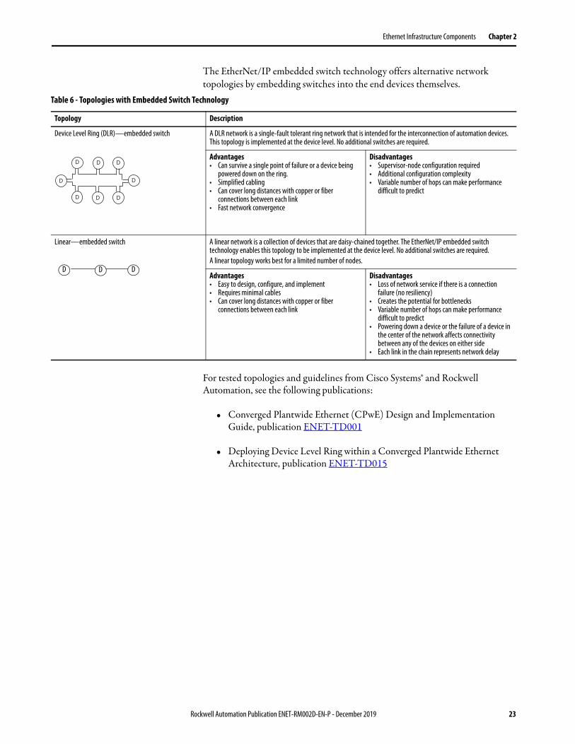
The EtherNet/IP embedded switch technology offers alternative network topologies by embedding switches into the end devices themselves.
For tested topologies and guidelines from Cisco Systems® and Rockwell Automation, see the following publications:
• Converged Plantwide Ethernet (CPwE) Design and Implementation Guide, publication ENET-TD001
• Deploying Device Level Ring within a Converged Plantwide Ethernet Architecture, publication ENET-TD015
Table 6 - Topologies with Embedded Switch Technology
Topology Description
Device Level Ring (DLR)—embedded switch A DLR network is a single-fault tolerant ring network that is intended for the interconnection of automation devices. This topology is implemented at the device level. No additional switches are required.
Advantages• Can survive a single point of failure or a device being
powered down on the ring.• Simplified cabling• Can cover long distances with copper or fiber
connections between each link• Fast network convergence
Disadvantages• Supervisor-node configuration required• Additional configuration complexity• Variable number of hops can make performance
difficult to predict
Linear—embedded switch A linear network is a collection of devices that are daisy-chained together. The EtherNet/IP embedded switch technology enables this topology to be implemented at the device level. No additional switches are required.A linear topology works best for a limited number of nodes.
Advantages• Easy to design, configure, and implement• Requires minimal cables• Can cover long distances with copper or fiber
connections between each link
Disadvantages• Loss of network service if there is a connection
failure (no resiliency)• Creates the potential for bottlenecks• Variable number of hops can make performance
difficult to predict• Powering down a device or the failure of a device in
the center of the network affects connectivity between any of the devices on either side
• Each link in the chain represents network delay
D D D
D D
D D D
D D D
Rockwell Automation Publication ENET-RM002D-EN-P - December 2019 23

Chapter 2 Ethernet Infrastructure Components
Media The actual wire that is used for the network is referred to as the physical media. Generally, shorter cable runs are less susceptible to EMI (electromagnetic interference) and RFI (radio-frequency interference) from electrical circuits, motors, and other machinery. Shielded wires further reduce interference.
Figure 2 - Select Ethernet Media
For more information about the media options, see the Ethernet Media Technical Data, publication 1585-TD001.
Do you have any of these:• Long distances?• High Magnetic fields?• High noise?
Fiber MediaRecommendations:• Multi-mode for general purposes, cost less• Single-mode yields higher distance, but costs more
Do you have excess amounts of any of these:• Radiated noise?• Conducted noise?• Metal conduit?
Copper STP (shielded twisted pair)Recommendations:• Requires proper grounding• Category 5e, 6, and 6a cables and
connectors
Copper UTP (unshielded twisted pair)Recommendations:• Requires proper grounding• Category 5e, 6, and 6a cables and connectors
Yes
Yes
No
No
24 Rockwell Automation Publication ENET-RM002D-EN-P - December 2019

Ethernet Infrastructure Components Chapter 2
Media Converters Media converters let you mix fiber and copper (twisted-pair) cables in the same system.
Use a switch or embedded switching technology, such as an ETAP1F or EN2TF module, to mix media. These devices have the following advantages over only physical media converters:
• Physical layer devices offer no buffering or advanced diagnostic features.• Physical layer devices are easily overrun by an EtherNet/IP system (no
buffering = lost data).• Layer 2 devices have buffering, QoS, and other management features.
Bridges A bridge is a device that isolates traffic between segments by selectively forwarding frames to their proper destination. A bridge is transparent to the network and protocol independent. More advanced devices that perform the same bridging function are commonly used instead of a bridge.
Fiber Link
Ethernet
Ethernet
Ethernet
Token Ring
Bridge
Bridge
Ethernet Ethernet
Access PointWork Group Bridge
Rockwell Automation Publication ENET-RM002D-EN-P - December 2019 25
Chapter 2 Ethernet Infrastructure Components
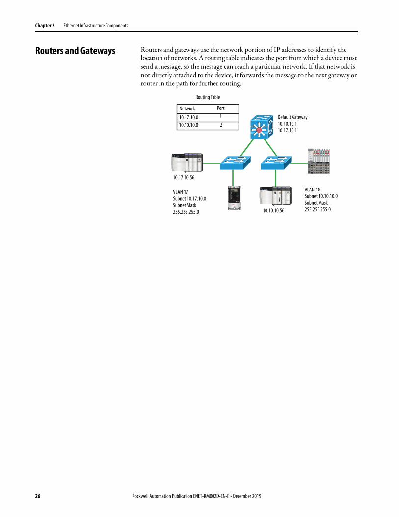
Routers and Gateways Routers and gateways use the network portion of IP addresses to identify the location of networks. A routing table indicates the port from which a device must send a message, so the message can reach a particular network. If that network is not directly attached to the device, it forwards the message to the next gateway or router in the path for further routing.
Routing Table
Network Port
10.17.10.010.10.10.0
1
2
10.17.10.56
VLAN 17Subnet 10.17.10.0Subnet Mask255.255.255.0 10.10.10.56
Default Gateway10.10.10.110.17.10.1
VLAN 10Subnet 10.10.10.0Subnet Mask255.255.255.0
26 Rockwell Automation Publication ENET-RM002D-EN-P - December 2019

Ethernet Infrastructure Components Chapter 2
Switches Switches connect devices on a network. They allow Ethernet-capable end devices to communicate with each other and with higher-level networks. Industrial rated switches are recommended for connecting industrial controls to a network. Managed industrial switches include advanced switch features for network functionality and diagnostics.
For more information about industrial switches from Rockwell Automation, see the Stratix Industrial Networks Infrastructure At-a-Glance, publication ENET-QR001.
Unmanaged versus Managed Switches
Unmanaged switches are relatively inexpensive and simple to set up, but they do not provide any management capabilities, security, or diagnostic information. Therefore, they are difficult to troubleshoot.
For unmanaged switches, make sure of the following:• Your application does not contain I/O traffic
or• Your application has I/O control and the following is true:
– The network is not directly connected to the IT network– All nodes on the network are Rockwell Automation devices– There is no potential to overload a device with traffic
Managed switches are typically more expensive than unmanaged switches and require some level of support for initial configuration and replacement. However, managed switches provide advanced features, which can enable better network performance in your control system. Managed switches are able to manage multicast traffic and provide diagnostics data, security options, and other advanced features.
Switch Type Advantages Disadvantages
Managed • Can manage multicast traffic• Diagnostics data• Security options• Additional advanced features• Network segmentation features• Network resiliency features
• More expensive• Requires some level of support and
configuration to start up and replace
Unmanaged • Inexpensive• Simple to set up• 'No Config' replacement
• No network segmentation• No diagnostic information• No port security• No traffic management• No network resiliency
Rockwell Automation Publication ENET-RM002D-EN-P - December 2019 27

Chapter 2 Ethernet Infrastructure Components
Autonegotiation
Autonegotiation enables devices to select the optimal way to communicate without requiring you to configure the devices.
All 100 Mbps and 1 Gbps devices support autonegotiation, but most existing 10 Mbps devices do not. To connect existing devices that use the slower rate, choose a switch that supports both speeds.
Full-duplex Mode
Ethernet is based on Carrier Sense Multiple Access/Collision Detect (CSMA/CD) technology. This technology places all nodes on a common circuit so they can all communicate as needed. The nodes must handle collisions and monitor their own transmissions so that other nodes have transmission time.
The data transmission mode that you configure determines how devices transmit and receive data.
Transmission Mode Features
Full-duplex Deterministic• Transmit and receive simultaneously• Transmit on the transmit pair and receive on the receive pairs• No collision detection, backoff, or retry• Collision free
Half-duplex Nondeterministic• One station transmits and the others listen• While transmitting, you do not receive, as no one else is transmitting• If someone else transmits while you are transmitting, then a collision occurs• Any Receive-while-Transmit condition is considered a collision
IMPORTANT The speed and duplex settings for the devices on the same Ethernet network must be the same to avoid transmission errors.• Fixed speed and full duplex settings are more reliable than autonegotiate
settings and are recommended for some applications.• If the module is connected to an unmanaged switch, leave Autonegotiate
port speed and duplex checked or communication can be impaired.• If you force the port speed and duplex with a managed switch, also force
the connected device to use the same settings.• If you connect two manually configured devices with different settings, a
high rate of transmission errors can occur.
28 Rockwell Automation Publication ENET-RM002D-EN-P - December 2019

Ethernet Infrastructure Components Chapter 2
Full-duplex mode eliminates collisions. Combined with the speed of the switches available today, you can eliminate the delays that are related to collisions or traffic in the switch. A a result, the EtherNet/IP network becomes well-suited for I/O control:
• If you are autonegotiating, make sure that you verify the connection.• If you are forcing speed and duplex on any link, make sure that you force at
both ends of the link.
Rockwell Automation Publication ENET-RM002D-EN-P - December 2019 29

Chapter 2 Ethernet Infrastructure Components
Notes:
30 Rockwell Automation Publication ENET-RM002D-EN-P - December 2019

Chapter 3
Ethernet Infrastructure Features
Topic Page
Authentication, Authorization, and Accounting (AAA) 32
Access Control Lists (ACLs) 35
Certificate Authority (CA) Trustpoints 36
Device Level Ring (DLR) 36
Dynamic Host Configuration Protocol (DHCP) 37
Flex Links 38
Internet Group Management Protocol (IGMP) 39
Logical Interfaces 40
Network Time Protocol (NTP) 43
Parallel Redundancy Protocol (PRP) 44
Port Security 44
Power over Ethernet (PoE) 46
Precision Time Protocol (PTP)/CIP Sync 47
Quality of Service (QoS) 51
Resilient Ethernet Protocol (REP) 52
Simple Network Management Protocol (SNMP) 61
Spanning Tree Protocol (STP) 62
Switched Port Analyzer (SPAN) or Port Mirroring 63
Virtual Local Area Networks (VLANs) 64
VLAN Trunking Protocol (VTP) 67
Rockwell Automation Publication ENET-RM002D-EN-P - December 2019 31

Chapter 3 Ethernet Infrastructure Features
Authentication, Authorization, and Accounting (AAA)
Authentication, authorization, and accounting (AAA) network security services provide the primary framework for intelligently controlling access to resources, policy enforcement, and usage audits. The AAA framework provides a way to configure three independent security functions in a consistent matter.
Authentication
Authentication provides a method to identify users, including login and password, challenge and response, messaging support, and, depending on the security protocol you select, encryption.
Authentication is the way that a user is identified before being allowed access to the network and network services. You configure AAA authentication by defining a named list of authentication methods, and then applying that list to various interfaces. The method list defines the types of authentication to be performed and the sequence in which they are performed.
The method list must be applied to a specific interface before any of the defined authentication methods is performed. If no other method list is defined, the default method list is automatically applied to all interfaces. A defined method list overrides the default method list.
Authorization
Authorization provides a method for remote access control. For example, you can use authorization for one-time authorization or authorization for each service, per-user account list and profile, user group support, and support of IP, IPX, ARA, and Telnet.
AAA authorization works by assembling a set of attributes that describe what the user is authorized to perform. These attributes are compared to the information contained in a database for a given user. The result is returned to AAA to determine the capabilities and restrictions for the user. The database can be stored on the access server or router or hosted remotely on a RADIUS or TACACS+ security server. Remote security servers, such as RADIUS and TACACS+, authorize users for specific rights by associating attribute-value (AV) pairs, which define those rights with the appropriate user.
All authorization methods must be defined through AAA. As with authentication, to configure AAA authorization, you define a named list of authorization methods, and then apply that list to various interfaces.
32 Rockwell Automation Publication ENET-RM002D-EN-P - December 2019

Ethernet Infrastructure Features Chapter 3
Accounting
Accounting provides a method for collecting and sending security server information. Accounting is used for billing, auditing, and reporting. Examples include user identities, start and stop times, executed commands, number of packets, and number of bytes.
Accounting enables you to track the services users access and the amount of network resources they consume. When AAA accounting is activated, the network access server reports user activity to the RADIUS or TACACS+ security server in the form of accounting records. Each accounting record is made of accounting AV pairs and is stored on the access control server. This data can then be analyzed for network management, client billing, and auditing. All accounting methods must be defined through AAA.
As with authentication and authorization, to configure AAA accounting, you define a named list of accounting methods, and then apply that list to various interfaces.
In many circumstances, AAA uses protocols such as RADIUS or TACACS+ to administer its security functions. If your device acts as a network access server, AAA is the means through which you establish communication between your network access server and your security server.
Server Protocols
You can use AAA with the following server protocols to provide secure services.
Table 7 - AAA Server Protocols
Server Protocol Description
Remote Authentication Dial-In User Service (RADIUS)
• Combines authentication and authorization. A RADIUS server regulates access to the network by verifying the identity of the users through the login credentials entered.
• Uses User Datagram Protocol (UDP) for client/server communication.• Encrypts only the password field.
Terminal Access Controller Access-Control System Plus (TACACS+)
• Separates authentication and authorization. Each function can be delegated to another server or different type of server.
• Uses Transmission Control Protocol (TCP) for client/server communication.• Encrypts the entire contents of the packet body, except for a TACACS+ header.
Lightweight directory access protocol (LDAP)
• Authenticates a user to the server via bind operation. LDAP supports authenticated and anonymous binds. An authenticated bind is performed when a root distinguished name (DN) and password are available. In the absence of a root DN and password, an anonymous bind is performed.
• Uses TCP or UDP for client/server communication.• Does not encrypt client/server traffic.
Rockwell Automation Publication ENET-RM002D-EN-P - December 2019 33

Chapter 3 Ethernet Infrastructure Features
Server Groups and Deadtimes
AAA server groups provide a way to group existing server hosts. If you group existing server hosts, you can select a subset of the configured server hosts and use them for a particular service.
Deadtime within a server group allows you to direct AAA traffic to separate groups of servers that have different operational characteristics. Deadtime is not limited to a global configuration. A separate timer is attached to each server host in every server group. When a server is unresponsive after numerous retransmissions and timeouts, the server is assumed to be dead. The timers attached to each server host in all server groups are triggered. Subsequent requests to a server once it is assumed to be dead are directed to alternate host timers, if configured. When the network access server receives a reply from the server, it checks and stops all configured timers for that server in all server groups.
If the timer has expired, the server to which the timer is attached is assumed to be alive. That server becomes the only server that can be tried for later AAA requests using the server groups to which the timer belongs.
Because one server has different timers and can have different deadtime values in the server groups, the same server can, in the future, have both dead and alive states.
New timers and the deadtime attribute slightly increase the size of the server group. The overall impact of the structure depends on the number and size of the server groups and how the servers are shared among server groups in a specific configuration.
Method Lists
AAA provides a granular approach to secure devices. You can set policies for either a group or individual and use different method lists for different access types.
When AAA is executed, the method lists are checked in order of configuration.
IMPORTANT To change the state of a server, you must start and stop all timers in all server groups.
EXAMPLE You can create a method list for authentication that requires the TACACS+ server at 10.0.0.1 to be used for console access and fall back to the local database. You can then use another method list for the VTY lines that requires a RADIUS server to be used and fall back to the local database.
34 Rockwell Automation Publication ENET-RM002D-EN-P - December 2019

Ethernet Infrastructure Features Chapter 3
Access Control Lists (ACLs) Access control lists (ACLs) provide basic security for a network by filtering traffic as it passes through a switch. ACLs permit or deny packets as they cross specified interfaces or VLANs.
Packet filtering provides security in the following ways:• Limits the access of traffic into a network• Restricts user and device access to a network• Prevents traffic from leaving a network
IP access lists reduce the chance of spoofing and denial-of-service attacks, and allow dynamic, temporary user-access through a firewall.
You can also use IP access lists for the following purposes other than security:• Control bandwidth• Restrict the content of routing updates• Redistribute routes• Trigger dial-on-demand (DDR) calls, • Limit debug output• Identify or classify traffic for Quality of Service (QoS)
An access list is a sequential list that consists of at least one permit statement and possibly one or more deny statements. If there are IP access lists, these statements can apply to IP addresses, upper-layer IP protocols, or other fields in IP packets.
Access Control Entries (ACEs)
An ACL contains an ordered list of access control entries (ACEs). Each ACE specifies whether to permit or deny packets. An ACE also specifies a set of conditions a packet must satisfy to match the ACE. The meaning of permit or deny depends on the context in which the ACL is used.
When a packet is received on a port, the switch compares the fields in the packet against any ACLs applied to the port. Based on the criteria in the ACL, the switch determines whether the packet has the required conditions to be forwarded. One by one, it tests packets against the conditions in an ACL. The first match decides whether the switch accepts or rejects the packets. Because the switch stops testing after the first match, the order of conditions in the list is critical. If no conditions match, the switch rejects the packet. If there are no restrictions, the switch forwards the packet. Otherwise, the switch drops the packet.
Rockwell Automation Publication ENET-RM002D-EN-P - December 2019 35

Chapter 3 Ethernet Infrastructure Features
Certificate Authority (CA) Trustpoints
CA trustpoints manage certificate requests and issue certificates to participating network devices. These services provide centralized security key and certificate management for the participating devices. Specific CA servers are known as trustpoints.
For secure HTTP connections, we highly recommend that you configure a CA trustpoint. Without a CA trustpoint, a temporary or a persistent self-signed certificate for the secure HTTP server (or client) is automatically generated.
• If a device is not configured with a host name and a domain name, a temporary self-signed certificate is generated. If the switch restarts, any temporary self-signed certificate is lost, and a new temporary new self-signed certificate is assigned.
• If a device is configured with a host and domain name, a persistent self-signed certificate is generated. This certificate remains active if you restart the device or disable the secure HTTP server. The certificate remains the next time you re-enable a secure HTTP connection.
Device Level Ring (DLR) Device Level Ring (DLR) is an EtherNet/IP™ protocol that is defined by the Open DeviceNet® Vendors’ Association (ODVA). DLR provides a means to detect, manage, and recover from one fault in a ring-based network.
A DLR network includes the following types of ring nodes.
Depending on their firmware capabilities, both devices and switches can operate as supervisors or ring nodes on a DLR network. Only switches can operate as redundant gateways.
For more information about DLR, see the EtherNet/IP Device Level Ring Application Technique, publication ENET-AT007.
Node Description
Ring supervisor A ring supervisor provides these functions:• Manages traffic on the DLR network• Collects diagnostic information for the networkA DLR network requires at least one node to be configured as ring supervisor.By default, the supervisor function is disabled on supervisor-capable devices.
Ring participants Ring participants provide these functions:• Process data that is transmitted over the network.• Pass on the data to the next node on the network.• Report fault locations to the active ring supervisor.When a fault occurs on the DLR network, ring participants reconfigure themselves and relearn the network topology.
Redundant gateways (optional)
Redundant gateways are multiple switches that are connected to one DLR network and also connected together through the rest of the network.Redundant gateways provide DLR network resiliency to the rest of the network.
36 Rockwell Automation Publication ENET-RM002D-EN-P - December 2019
Ethernet Infrastructure Features Chapter 3
Dynamic Host Configuration Protocol (DHCP)
Every device in an IP-based network must have a unique IP address. Dynamic Host Configuration Protocol (DHCP) assigns IP address information from a pool of available addresses to newly connected devices (DHCP clients) in the network. A switch can operate as a DHCP server by automatically assigning IP addresses to connected devices.
IP Address Pools
An address pool is a range of available IP addresses that a DHCP server uses to assign to connected devices. You can configure and maintain one or more IP address pools on a DHCP server. Each IP address that you add to a pool must be unique and not currently used by another device in the network.
DHCP Snooping
DHCP snooping acts like a firewall between untrusted hosts and trusted DHCP servers. DHCP snooping performs the following activities:
• Validates DHCP messages received from untrusted sources and filters out invalid messages.
• Builds and maintains the DHCP snooping binding database, which contains information about untrusted hosts with leased IP addresses.
• Uses the DHCP snooping binding database to validate subsequent requests from untrusted hosts.
DHCP Persistence
Stratix® switches can be set to operate as a DHCP server to provide DHCP persistence. With DHCP persistence, you can assign a specific IP address to each port. Any device that is attached to that port receives the same IP address.
Device Level Ring (DLR) DHCP
A switch configured as a DLR ring supervisor can also act as a DHCP server to assign designated IP addresses to ring participants. Assignment of IP addresses is based on ring participant position. If a ring participant fails, a replacement device can be installed in the same position in the ring and automatically receive the same IP address as the replaced device. However, the DLR ring does not provide an IP address unless the participant list exists. This list is created when the DLR ring is closed with no faults. For more information about DLR DHCP, see the EtherNet/IP Device Level Ring Application Technique, publication ENET-AT007.
Rockwell Automation Publication ENET-RM002D-EN-P - December 2019 37

Chapter 3 Ethernet Infrastructure Features
Flex Links The Flex Links protocol for Ethernet switches provides link-level, physical redundancy in redundant star topologies. A pair of Layer 2 switch ports is configured to act as a backup to each other:
• Requires redundant star topology • Active/standby port scheme
– Provides an alternate path if there are failures (avoids loops)– No bandwidth aggregation– Equal speed ports recommended– Provides fast fail over for multicast traffic
Distribution Switches
Catalyst 3850 Switch Stack
A
S
S
AStratix 5700 Access Switches
A = ActiveS = Standby
SA
38 Rockwell Automation Publication ENET-RM002D-EN-P - December 2019
Ethernet Infrastructure Features Chapter 3
Internet Group Management Protocol (IGMP)
IGMP is a communication protocol that manages the membership of IP multicast groups. I/O communication uses IP multicast to distribute I/O control data, which is consistent with the CIP™ Producer/Consumer model. Without IGMP, switches treat multicast packets the same as broadcast packets. Multicast packets are retransmitted to all ports. IGMP manages multicast traffic with these features:
• Querier functionality manages a table that lists the devices that participate in multicast groups.
• Snooping functionality inspects packets from devices and forwards multicast data to only devices that request the data.
IGMP Snooping with Querier
Switches can use IGMP snooping to constrain the flooding of multicast traffic. IGMP snooping dynamically configures Layer 2 interfaces so that multicast traffic is forwarded to only those interfaces that are associated with IP multicast devices.
IGMP snooping requires the LAN switch to snoop on the IGMP transmissions between the host and the router and track multicast groups and member ports. When the switch receives an IGMP report from a host for a particular multicast group, it adds the host port number to the forwarding table entry. When the switch receives an IGMP Leave Group message from a host, it removes the host port from the table entry. It also periodically deletes entries if it does not receive IGMP membership reports from the multicast clients.
The multicast router, also known as the querier, sends out periodic general queries to all VLANs. All hosts that are interested in this multicast traffic send join requests and are added to the forwarding table entry. The querier creates one entry per VLAN in the IGMP snooping IP multicast forwarding table for each group from which it receives an IGMP join request.
IGMP protocol has versions 1, 2, and 3. Products from Rockwell Automation support versions 1 or 2. IGMP protocol version 2 negotiates the active querier automatically and that task is assigned to the IGMP capable device with the lowest IP address on a given VLAN.
IGMP querier functionality typically resides on the router within a network. If you do not have a router, place the querier on a centrally located IGMP-capable device on the network. Configure the querier with the first available IP address on a VLAN.
Rockwell Automation Publication ENET-RM002D-EN-P - December 2019 39

Chapter 3 Ethernet Infrastructure Features
Multicast Group Limits
Different devices have different multicast group limits. To determine or modify the default number of multicast groups for a device, see the user manual for that device.
Logical Interfaces A logical interface is a virtual interface, rather than a physical interface, which you can configure on an Ethernet switch. Types of logical interfaces include the following:
• Port channels, also known as EtherChannels• Loopback interfaces• Switch virtual interfaces (SVIs)
Port Channels or EtherChannels
A port channel, also known as an EtherChannel, combines multiple physical switch ports into one logical connection. This connection provides physical connection redundancy and increases bandwidth through load balancing across the multiple ports. The port channel provides fault-tolerance and high-speed links between switches, routers, and servers:
• Supports Link Aggregation Control Protocol (LACP) port aggregation—IEEE 802.3ad
• Requires a redundant star topology• Provides resiliency between connected switches if a wire is broken or
damaged
Fault tolerance is a key aspect of port channels. If a link fails, the technology automatically redistributes traffic across the remaining links. This automatic recovery takes less than 1 second and is transparent to network applications and the end user.
For example, four Fast Ethernet switch ports that operate at 100 Mbps can be assigned to a port channel to provide full-duplex bandwidth of 400 Mbps. If one of the ports in the channel becomes unavailable, traffic is carried over the remaining ports within the channel.
40 Rockwell Automation Publication ENET-RM002D-EN-P - December 2019

Ethernet Infrastructure Features Chapter 3
Requirements and Restrictions
All ports in a port channel must have the same characteristics:
• All are applied with the Switch for Automation Smartports role and belong to the same VLAN.
• All are either 10/100 ports, or all are 10/100/1000 ports. You cannot group a mix of 10/100 and 10/100/1000 ports in a port channel.
• All are enabled. A disabled port in a port channel is treated as a link failure, and its traffic is transferred to one of the remaining ports in the channel.
Port Channel Example
Figure 3 shows two port channels. Two full-duplex 10/100/1000-Mbps ports on Switches A and C create a port channel with a bandwidth of up to 4 Gbps between both switches. Similarly, two full-duplex 10/100 ports on Switches B and D create a port channel with a bandwidth of up to 400 Mbps between both switches.
If one of the ports in the port channel becomes unavailable, traffic is sent through the remaining ports within the port channel.
Figure 3 - Port Channel Example
Spanning Tree Protocol (STP) and Port Channels
You can use STP with a port channel. STP treats all links as one connection. Without the use of a port channel, STP shuts down any redundant links between switches until one connection goes down. By using port channels, you enable full use of all available links between two devices.
IMPORTANT Do not enable Layer 3 addresses on the physical port channel interfaces.
Servers
Switch A Switch B
Switch C Switch D
PCMAC Guest
Network ManagementAccess
PointRouter with Firewall
WAN/Internet
Printer
Printer
Rockwell Automation Publication ENET-RM002D-EN-P - December 2019 41

Chapter 3 Ethernet Infrastructure Features
Loopback Interfaces
A loopback interface is a virtual interface on an Ethernet switch that remains in an operational state. A loopback interface can provide a stable interface for a Layer 3 address. This address can be the source address when a device sends data to another device, and you always want the receiving device to see the same source IP address. For example, a loopback interface is useful in networks with multiple equal-cost paths. The packets from a networking device use the IP address from the outbound interface as the source address for the packets. In a network with two or more equal-cost paths from the networking device to the receiving host, each packet can use a different outbound interface.
Switch Virtual Interfaces (SVIs)
An SVI is a virtual interface in the switch that allows a VLAN to have an IP address and additional configuration. An SVI allows traffic to be routed out of a Layer 2 domain without requiring a physical interface.
Network Address Translation (NAT)
NAT is a service that translates one IP address to another IP address. This service is useful if you reuse IP addresses throughout a network. NAT enables devices that share one IP address on a private subnet to be segmented into multiple, identical private subnets while maintaining unique identities on the public subnet.
There are two types of NAT implementations:
• One-to-many—Multiple nodes are mapped to one public identity to get onto the Internet, such as in a home network. This type of implementation conserves public IP addresses and offers some protection against attacks from the Internet.
• One-to-one—Each node on the network translates to another identity on another network. This type of implementation is used in manufacturing to integrate machinery onto a larger network, such as the plant network, without requiring addressing changes at the machine level.
42 Rockwell Automation Publication ENET-RM002D-EN-P - December 2019
Ethernet Infrastructure Features Chapter 3
Allen-Bradley Products That Support NAT
The following Allen-Bradley® products support one-to-one NAT:• Stratix 5400, 5410, and 5800 switches• Stratix 5700 and ArmorStratix™ 5700 switches• Network Address Translation Device (9300-ENA)• 1783 Configurable NAT Router (1783-NATR)
NAT implementations vary by product. For details about how NAT functions on a specific product, see the product user manual.
Network Time Protocol (NTP) Network Time Protocol (NTP), defined in RFC 1305, synchronizes clocks across packet-based networks. NTP uses a two-way time transfer mechanism between a master and a slave.
NTP can synchronize devices in a tightly controlled network. An Ethernet switch can use NTP as a time source for PTP. You can then correlate data that is generated in the PTP network with data in the enterprise network that uses NTP as a time source.
NTP-based networks maintain an approximate synchronization to Coordinated Universal Time (UTC) and handle events like leap seconds. NTP accuracy is within the millisecond range.
For Integrated Motion on the EtherNet/IP network applications, we recommend that you use Precision Time Protocol (PTP), also referred to as CIP Sync™. PTP accuracy is within the nanosecond range.
If you use NTP, we recommend that you have a local time source on your network for stability. NTP time that is received from the Internet can introduce inconsistencies.
Rockwell Automation Publication ENET-RM002D-EN-P - December 2019 43

Chapter 3 Ethernet Infrastructure Features
Parallel Redundancy Protocol (PRP)
Parallel Redundancy Protocol (PRP) is defined in international standard IEC 62439-3 and provides high-availability in Ethernet networks. PRP technology creates seamless redundancy by sending duplicate frames to two independent network infrastructures, which are known as LAN A and LAN B.
A PRP network includes the following components.
For more information about PRP, see the EtherNet/IP Parallel Redundancy Protocol Application Technique, publication ENET-AT006.
Port Security An Ethernet switch has dynamic and static methods for limiting the MAC addresses (MAC IDs) that can access a given port. For information about how port security is implemented on a particular product, refer to the product user manual.
Dynamic Secure MAC Address (MAC ID)
With dynamic limiting of MAC IDs, Smartport roles have a maximum number of MAC IDs that are permitted to use the port. For example, the Smartport role ‘Automation Device’ configures the port for a maximum of one MAC ID. The MAC ID is dynamic, meaning the switch learns the first source MAC ID to use the port. Attempts by any other MAC ID to access the port are denied. If the link becomes inactive, the switch dynamically relearns the MAC ID to be secured.
Static Secure MAC Address (MAC ID)
Static MAC IDs on the port limits communication to only devices with those MAC IDs. These static IDs become part of the saved configuration on the switch. This method provides strong security. However, it also requires reconfiguration when the device that is connected to the port is replaced because the new device has a different MAC ID than the old device.
Component Description
LAN A and LAN B Redundant, active Ethernet networks that operate in parallel.
Double attached node (DAN) An end device with PRP technology that connects to both LAN A and LAN B.
Single attached node (SAN) An end device without PRP technology that connects to either LAN A or LAN B.A SAN does not have PRP redundancy.
Redundancy box (RedBox) A switch with PRP technology that connects devices without PRP technology to both LAN A and LAN B.
Virtual double attached node (VDAN)
An end device without PRP technology that connects to both LAN A and LAN B through a RedBox.A VDAN has PRP redundancy and appears to other nodes in the network as a DAN.
Infrastructure switch A switch that connects to either LAN A or LAN B and is not configured as a RedBox.
44 Rockwell Automation Publication ENET-RM002D-EN-P - December 2019

Ethernet Infrastructure Features Chapter 3
Security Violations
The following scenarios cause a security violation:
• The address table of a port is full and another device attempts to access the port. The address table is full when it reaches the maximum number of permitted MAC addresses. The count includes both static and dynamic addresses.
• An address that is learned or configured on one secure interface is seen on another secure interface in the same VLAN.
When a violation occurs, the following occurs:
• The port goes into Restrict mode. In this mode, the port drops any traffic from an address that is not in the list of permitted MAC addresses.
• You are notified that a security violation has occurred.
• An SNMP trap is sent, a syslog message is logged, and the violation counter increments.
• If the switch is part of the I/O configuration in your controller program, the switch notifies the controller of the event via an input bit. The controller program then determines how to proceed. For example, the controller can shut down that switch port, send an alarm to the HMI, or shut down the device.
Rockwell Automation Publication ENET-RM002D-EN-P - December 2019 45

Chapter 3 Ethernet Infrastructure Features
Power over Ethernet (PoE) Power over Ethernet (PoE) provides power to end devices over a copper Ethernet cable. Switches and expansion modules with PoE ports are software-configurable and provide automatic detection and power budgeting. PoE is implemented following the specifications in IEEE 802.3af (2003) and IEEE 802.3at (2009), which accommodate different power levels. PoE+ accommodates higher power budgets than PoE.
Depending on the device and software version, PoE provides these features:
• Automatic detection and power budgeting. The switch maintains a power budget, monitors and tracks requests for power, and grants power only when it is available.
• Support for Cisco Discovery Protocol (CDP) with power consumption. CDP applies only when using Stratix managed switches with Cisco end devices. The powered Cisco end device notifies the switch of the amount of power it is consuming.
• Support for high- and low-priority PoE/PoE+ ports. When two power-supply modules are installed, the system has enough power to support all ports as PoE/PoE+ ports. If one power-supply module fails, the system drops power to the low-priority ports. Power to the high priority ports remains uninterrupted. If there is not enough power for one supply to support all high priority ports, ports are dropped according to port number from highest to lowest.
IMPORTANT Rockwell Automation recommends that you review the installation of the PoE-powered end device per IEEE standards. The PoE-powered end device receives its ground reference from the ground of the switch. The PoE end device must not be tied to a separate ground. Review the IEEE 802.3af-2003 Standard for Information Technology.
46 Rockwell Automation Publication ENET-RM002D-EN-P - December 2019

Ethernet Infrastructure Features Chapter 3
Precision Time Protocol (PTP)/CIP Sync
Precision Time Protocol (PTP) is defined in the IEEE 1588 standard. CIP Sync time synchronization on products from Rockwell Automation refers to PTP. The protocol enables precise synchronization of clocks in measurement and control systems. Clocks are synchronized with nanosecond accuracy over an EtherNet/IP network. PTP enables systems that include clocks of various precisions, resolution, and stability to synchronize. PTP generates a master-slave relationship among the clocks in the system. All clocks derive their time from a clock that is selected as the Grandmaster clock. PTP is designed for local systems that require clock accuracy and precision beyond what is attainable with Network Time Protocol (NTP).
PTP Clocks
A PTP network is composed of PTP-enabled devices and devices that do not use PTP. These PTP-enabled devices typically consist of the clock types that are described in Table 8.
Table 8 - PTP Clock Types
Clock Type Description
Grandmaster clock Within a PTP domain, the Grandmaster clock is the primary source of time for clock synchronization via PTP. The Grandmaster clock usually has a precise time source, such as a GPS or atomic clock. When the network does not require any external time reference and only internal synchronization, the Grandmaster clock can free run.
Ordinary clock An ordinary clock is a PTP clock with one PTP port. It functions as a node in a PTP network. The BMCA can select the ordinary clock as a master or slave within a subdomain. Ordinary clocks are the most common clock type on a PTP network. They function as end nodes on a network that is connected to devices that require synchronization. Ordinary clocks have various interfaces to external devices.
Boundary clock A boundary clock in a PTP network operates on a switch or router. Boundary clocks have these characteristics:• Have multiple PTP ports, and each port provides access to a separate PTP communication path.• Provide an interface between PTP domains. They intercept and process all PTP messages, and pass all other network traffic. • Use the BMCA to select the best clock seen by any port. The selected port is then set as a slave. The master port synchronizes the clocks that
are connected downstream, while the slave port synchronizes with the upstream master clock.• Recalculate and cascade time within across VLANs. Any errors that occur are also cascade across VLANs.
Transparent clock The role of transparent clocks in a PTP network is to update the time-interval field that is part of the PTP event message. This update compensates for switch delay and has an accuracy of within 1 picosecond.Transparent clocks have these characteristics:• Unlike boundary clocks, transparent clocks do not recalculate and cascade time across VLANs. • Transparent clocks do not contribute to the master/slave hierarchy.• A switch that functions as a transparent clock becomes invisible in the PTP network. Any device that synchronizes time with a transparent
clock does not show the transparent clock as its parent clock.
NTP-PTP clock An NTP-PTP clock functions as the Grandmaster clock and boundary clock:• As Grandmaster, it uses PTP while deriving the time source from Network Time Protocol (NTP).• If configured as a secondary Grandmaster, it functions as a boundary clock to forward time, helping to maintain that all devices on the PTP
network remain synchronized in a failover scenario.An NTP-PTP clock enables tightly controlled PTP zones, such as motion applications, to maintain time relative to other devices outside the PTP zone that use NTP. In this scenario, NTP-PTP clock time is beneficial for logging and event tracking.
Rockwell Automation Publication ENET-RM002D-EN-P - December 2019 47

Chapter 3 Ethernet Infrastructure Features
Ethernet Switches and Delays
In an Ethernet network, switches provide a full-duplex communication path between network devices. Switches send data packets to destinations via address information contained in the packets. When the switch attempts to send multiple packets simultaneously, packets in the buffer experience latency before transmission. When not accounted for, this delay can cause device clocks on the network to lose synchronization with one another.
Additional delays can occur when packets that enter a switch are stored in local memory while the switch searches the MAC address table to verify the packet contents. This process causes variations in packet forwarding time latency, and these variations can result in asymmetrical packet delay times.
PTP can help a network compensate for these latency and delay problems by adjusting device clocks so that they stay synchronized with one another.
Message-Based Synchronization
To achieve clock synchronization, PTP requires an accurate measurement of the communication path delay between the time source (master) and the receiver (slave). PTP sends messages between the master and slave device to determine the delay measurement. Then, PTP measures the exact message transmit and receive times and uses these times to calculate the communication path delay. PTP then adjusts current time information for the calculated delay.
This delay measurement principle determines path delay between devices on the network. The local clocks are adjusted for this delay with a series of messages that are sent between masters and slaves. The one-way delay time is calculated by averaging the path delay of the transmit and receive messages. This calculation assumes a symmetrical communication path. However, switched networks do not necessarily have symmetrical communication paths, due to the buffering process.
48 Rockwell Automation Publication ENET-RM002D-EN-P - December 2019

Ethernet Infrastructure Features Chapter 3
Figure 4 shows a typical 1588 PTP network that includes the following: • Grandmaster clock• Boundary clocks• Transparent clocks• End devices, such as controllers or drives
In this example, time slaves that connect to transparent clocks show the Stratix 5410 switch as both parent and Grandmaster. Time slaves that connect to boundary clocks show the directly connected boundary clock device as the parent and the Stratix 5410 switch as the Grandmaster.
Figure 4 - PTP Network Example
Com
IN2
Ref
IN1
AlarmIN1 IN2 OUT
DC+
Pwr A
ExpressSetup
Con
sole
DC-
DC+
Pwr B
Com
IN2
Ref
IN1
AlarmIN1 IN2 OUT
DC+
Pwr A
ExpressSetup
Con
sole
DC-
DC+
Pwr B
Esc SelEsc Sel
Com
IN2
Ref
IN1
AlarmIN1 IN2 OUT
DC+
Pwr A
ExpressSetup
Con
sole
DC-
DC+
Pwr B
M Time Master
S Time Slave
Stratix 5410 with GPS/NTP as Grandmaster Clock
Transparent Clock
Transparent Clock
S
S S
S S
S SS
S S
MM M
M M M
M M
Boundary Clock
Boundary Clock
Rockwell Automation Publication ENET-RM002D-EN-P - December 2019 49

Chapter 3 Ethernet Infrastructure Features
Best Master Clock Algorithm
The Best Master Clock Algorithm (BMCA) is the basis of PTP functionality. The BMCA specifies how each clock on the network determines the best master clock in its subdomain of all clocks it can detect, including itself. the result of the BMCA is one Grandmaster clock for the entire time domain.The BMCA runs on the network continuously and quickly adjusts for changes in network configuration.
The BMCA uses the following criteria to determine the best master clock in the subdomain:
• Clock quality (for example, GPS is considered the highest quality)• Clock accuracy of its time base• Stability of the local oscillator• Closest clock to the Grandmaster
The BMCA also makes sure that clock conflicts do not occur on the PTP network, which results in these benefits:
• Clocks do not have to negotiate with one another.
• There is no misconfiguration. For example, there are not two master clocks or no master clocks as a result of the master clock identification process.
PTP Clock Modes
PTP synchronization behavior depends on the PTP clock mode that you configure on the switch. For more information about these modes, refer to the user manual for the switch. See also the Converged Plantwide Ethernet Design and Implementation Guide, publication ENET-TD001.
50 Rockwell Automation Publication ENET-RM002D-EN-P - December 2019

Ethernet Infrastructure Features Chapter 3
Quality of Service (QoS) Typically, networks operate on a best-effort delivery basis, which means that all traffic has equal priority and an equal chance of being delivered in a timely manner. When congestion occurs, all traffic has an equal chance of being delayed or dropped.
When you configure Quality of Service (QoS), you can select specific network traffic, prioritize it according to its relative importance, and use congestion-management and congestion-avoidance techniques to give preferential treatment. A network with QoS makes network performance more predictable and bandwidth utilization more effective.
Rockwell Automation EtherNet/IP devices prioritize traffic internally. QoS at the switch level adds another level of prioritization. QoS does not increase bandwidth—QoS gives preferential treatment to some network traffic at the expense of others.
Not all network traffic should be treated equally. The automation network can have motion traffic, voice traffic, and email traffic all being transmitted simultaneously over the network. To minimize application latency and jitter, control data must have priority within the cell or area zone. Control data is more sensitive to latency and jitter than information data.
QoS lets you set up priority queues in the managed switches on the network. In the automation example, give motion traffic the highest priority for network usage. Voice traffic can go second (it also has low tolerance for delay), and email traffic has the lowest priority queue. This priority results in the least amount of delay possible on the motion control.
Ingress Actions Egress Actions
Classification Policing/Metering MarkingQueue/ScheduleCongestion Control
Distinguish traffic by examining Layer 2/3/4 labels and QoS fields. QoS changed depending on trust state at port.
Make sure that conformance is to a specified rate.
DSCP-CoS orCoS DSCP Mapping
4 queues/or with priority scheduling
Rockwell Automation Publication ENET-RM002D-EN-P - December 2019 51

Chapter 3 Ethernet Infrastructure Features
QoS Guidelines
Follow these guidelines with QoS:
• Manage the output queues based on application needs. Schedule precision and motion control packets in the highest priority queue.
• QoS is integrated into Stratix switch configurations.
• Stratix switches have default QoS policies that give preferential treatment to network traffic in an industrial automation and control system at the expense of other network traffic.
• Deploy QoS consistently throughout Industrial Automation and Control System Network.
Resilient Ethernet Protocol (REP)
REP provides an alternative to Spanning Tree Protocol (STP). REP does the following:
• Controls a group of ports that are connected in a segment• Makes sure that the segment does not create any bridging loops• Responds to link failures within the segment• Provides a basis for constructing more complex networks• Supports VLAN load balancing
A REP segment is a chain of ports that are connected to each other and configured with a segment ID. Each segment consists of these ports:
• Standard (non-edge) segment ports• Two user-configured edge ports
A switch can have no more than two ports that belong to the same segment, and each segment port can have only one external neighbor. A segment can go through a shared medium, but on any link, only two ports can belong to the same segment. REP is supported only on trunk ports.
REP supports closed and open rings in various topologies:
• Redundant networks can be built with REP segments
• REP is the only ring resiliency protocol applicable to both industrial and IT applications
52 Rockwell Automation Publication ENET-RM002D-EN-P - December 2019

Ethernet Infrastructure Features Chapter 3
REP Segments
Figure 5 shows an example of a segment consisting of six ports that are spread across four switches. Ports E1 and E2 are configured as edge ports. When all ports are operational, one port is blocked, shown by the diagonal line. This blocked port is also known as the alternate port (ALT port). When there is a failure in the network, the blocked port returns to the forwarding state to minimize network disruption.
Figure 5 - REP Open Segment
The segment shown in Figure 5 is an open segment. There is no connectivity between the two edge ports. The REP segment cannot cause a bridging loop, and you can safely connect the segment edges to any network. All hosts that connect to switches inside the segment have two possible connections to the rest of the network through the edge ports. However, only one connection is accessible at any time. If a failure occurs on any segment or on any port on a REP segment, REP unblocks the ALT port to enable connectivity through the other gateway.
The segment shown in Figure 6 is a closed segment, also known as ring segment, with both edge ports located on the same router. With this configuration, you can create a redundant connection between any two routers in the segment.
Figure 6 - REP Ring Segment
Edge Port
Blocked Port
Link Failure
Rockwell Automation Publication ENET-RM002D-EN-P - December 2019 53

Chapter 3 Ethernet Infrastructure Features
REP segments have the following characteristics:
• If all ports in a segment are operational, one port (referred to as the ALT port) is in the blocked state for each VLAN. If VLAN load balancing is configured, two ALT ports in the segment control the blocked state of VLANs.
• If a port is not operational and cause a link failure, all ports forward traffic on all VLANs to achieve connectivity.
• If there is a link failure, alternate ports are unblocked as quickly as possible. When the failed link is restored, a logically blocked port per VLAN is selected with minimal disruption to the network.
You can construct almost any type of network that is based on REP segments.
In access ring topologies, it is possible that the neighboring switch does not support REP as shown in Figure 7. In this case, you can configure the non-REP facing ports (E1 and E2) as edge no-neighbor ports. The edge no-neighbor port can be configured to send an STP topology change notice (TCN) towards the aggregation switch.
Figure 7 - Edge No-neighbor Ports
REP Not Supported
REP Ports
E1 and E2 are configured as edge no-neighbor ports.
54 Rockwell Automation Publication ENET-RM002D-EN-P - December 2019

Ethernet Infrastructure Features Chapter 3
REP Limitations
REP has these limitations:
• You must configure each segment port; an incorrect configuration can cause forwarding loops in the networks.
• REP can manage only a one failed port within the segment; multiple port failures within the REP segment cause loss of network connectivity.
• Configure REP only in networks with redundancy. A network with REP and no redundancy causes loss of connectivity.
Link Integrity
REP does not use an end-to-end polling function between edge ports to verify link integrity. It implements local link failure detection. The REP Link Status Layer (LSL) detects its REP-aware neighbor and establishes connectivity within the segment. All VLANs are blocked on an interface until the neighbor is detected. After the neighbor is identified, REP determines which neighbor port becomes the alternate port and which ports forward traffic.
Each port in a segment has a unique port ID. The port ID format is similar to the format used by the spanning tree algorithm: a port number (unique on the bridge) associated to a MAC address (unique in the network). When a segment port is coming up, its LSL sends packets with the segment ID and the port ID. The port is declared as operational after it performs a three-way handshake with a neighbor in the same segment.
A segment port does not become operational in these scenarios:• No neighbor has the same segment ID.• Multiple neighbors have the same segment ID.• A neighbor does not acknowledge a local port as a peer.
Each port creates an adjacency with its immediate neighbor. After the neighbor adjacencies are created, the ports negotiate with each other to determine the blocked port for the segment, which functions as the alternate port. All other ports become unblocked. By default, REP packets are sent to a bridge protocol data unit-class MAC address. The packets can also be sent to a Cisco multicast address, which is used only to send blocked port advertisement (BPA) messages when there is a failure in the segment. Devices that do not use REP drop the packets.
Rockwell Automation Publication ENET-RM002D-EN-P - December 2019 55

Chapter 3 Ethernet Infrastructure Features
Fast Convergence
REP runs on a physical link basis and not on a per-VLAN basis. Only one hello message is required for all VLANs, which reduces the load on the protocol. We recommend that you create VLANs consistently on all switches in a given segment and configure the same allowed VLANs on the REP trunk ports.
To avoid the delay introduced by software that relays messages, REP allows some packets to be flooded to a regular multicast address. These messages operate at the hardware flood layer (HFL) and are flooded to the entire network, not just the REP segment. Switches that do not belong to the segment treat them as data traffic. You can control flooding of these messages by configuring an administrative VLAN for the entire domain or for a particular segment.
VLAN Load Balancing
One edge port in the REP segment acts as the primary edge port. Another edge port acts as the secondary edge port. The primary edge port always participates in VLAN load balancing in the segment. REP VLAN balancing is achieved by blocking some VLANs at a configured alternate port and all other VLANs at the primary edge port.
When you configure VLAN load balancing, you can specify the alternate port in one of three ways:
• By entering the port ID of the interface. To identify the port ID of a port in the segment, enter the show interface rep detail interface configuration command for the port.
• By entering the preferred keyword to select the port that you previously configured as the preferred alternate port.
• By entering the neighbor offset number of a port in the segment, which identifies the downstream neighbor port of an edge port. The neighbor offset number range is –256…+256; a value of 0 is invalid. The primary edge port has an offset number of 1; positive numbers above 1 identify downstream neighbors of the primary edge port. Negative numbers indicate the secondary edge port (offset number -1) and its downstream neighbors.
IMPORTANT To configure the offset numbers on the primary edge port, identify the downstream position of a port from the primary (or secondary) edge port. Never enter an offset value of 1 because that is the offset number of the primary edge port.
56 Rockwell Automation Publication ENET-RM002D-EN-P - December 2019

Ethernet Infrastructure Features Chapter 3
Figure 8 shows neighbor offset numbers for a segment, where E1 is the primary edge port and E2 is the secondary edge port. The red numbers inside the ring are numbers offset from the primary edge port; the black numbers outside of the ring show the offset numbers from the secondary edge port. You can identify all ports except the primary edge port by using one of these methods:
• Apositive offset number (downstream position from the primary edge port)
• A negative offset number (downstream position from the secondary edge port).
If E2 becomes the primary edge port, its offset number becomes 1 and E1 becomes -1.
Figure 8 - Neighbor Offset Numbers in a Segment
When the REP segment is complete, all VLANs are blocked. When you configure VLAN load balancing, you must also configure triggers in one of two ways:
• Manually trigger VLAN load balancing at any time on the switch with the primary edge port.
• Configure a preempt delay time. After a link failure and recovery, VLAN load balancing begins after the configured preemption time period elapses. The delay timer restarts if another port fails before the time has elapsed.
When VLAN load balancing is triggered, the primary edge port sends out a message to alert all interfaces in the segment about the preemption. When the secondary port receives the message, the message is sent to the network. The message does the following:
• Notifies the alternate port to block the set of VLANs specified in the message.
• Notifies the primary edge port to block the remaining VLANs.
IMPORTANT When VLAN load balancing is configured, it does not start working until triggered by either manual intervention or a link failure and recovery.
E1 = Primary Edge PortE2 = Secondary Edge Port
Offset numbers from the primary edge portOffset numbers from the secondary edge port (negative numbers)
Rockwell Automation Publication ENET-RM002D-EN-P - December 2019 57

Chapter 3 Ethernet Infrastructure Features
You can also configure a particular port in the segment to block all VLANs. Only the primary edge port initiates VLAN load balancing, which is not possible if the edge port on each end does not terminate the segment. The primary edge port determines the local VLAN load-balancing configuration.
Reconfigure the primary edge port to reconfigure load balancing. When you change the load-balancing configuration, the primary edge port waits for the configured preempt delay period after a port failure and recovery, before executing the new configuration. If you change an edge port to a regular segment port, the existing VLAN load-balancing status does not change. A new edge port can cause a new topology configuration.
Spanning Tree Interaction
REP does not interact with STP, but it can coexist. A port that belongs to a segment is removed from spanning tree control and STP BPDUs are not accepted or sent from segment ports. Therefore, STP cannot run on a segment.
To change an STP ring configuration to a REP segment configuration, configure one port in the ring as part of the segment. Then configure contiguous ports to minimize the number of segments. Each segment always contains a blocked port, so multiple segments means multiple blocked ports and a potential loss of connectivity. When the segment has been configured in both directions up to the location of the edge ports, you then configure the edge ports.
REP Ports
REP segments consist of failed, open, or alternate ports:
• A port configured as a regular segment port starts as a failed port.
• After the neighbor adjacencies are determined, the port transitions to alternate port state, blocking all VLANs on the interface. Blocked-port negotiations occur, and when the segment settles, one blocked port remains in the alternate role and all other ports become open ports.
• When a failure occurs in a link, all ports move to the Failed state. When the alternate port receives the failure notification, it changes to the Open state and forwards all VLANs.
A regular segment port that is converted to an edge port, or an edge port that is converted to a regular segment port, does not always result in a topology change. If you convert an edge port into a regular segment port, VLAN load balancing is not implemented unless it has been configured. For VLAN load balancing, you must configure two edge ports in the segment.
58 Rockwell Automation Publication ENET-RM002D-EN-P - December 2019

Ethernet Infrastructure Features Chapter 3
A segment port that is reconfigured as a spanning tree port restarts according to the spanning tree configuration. By default, the port is a designated blocking port. If PortFast is configured or if STP is disabled, the port goes into the forwarding state.
Requirements and Restrictions
Follow these guidelines when configuring REP:
• We recommend that you begin by configuring one port and then configure contiguous ports to minimize the number of segments and the number of blocked ports.
• If more than two ports in a segment fail when no external neighbors are configured, one port goes into a forwarding state for the data path. This state helps to maintain connectivity during configuration. When the external neighbors for the failed ports are configured, the ports go through the alternate port state transitions. Eventually, the ports go to an open state or remain as alternate ports based on the alternate port selection mechanism.
• REP ports must be Layer 2 IEEE 802.1Q or Trunk ports.
• REP interfaces come up in a blocked state and remain in a blocked state until they are safe to be unblocked. To avoid sudden connection losses, be aware of interfaces with a blocked state.
• Be careful when configuring REP through a Telnet connection. REP blocks all VLANs until another REP interface sends a message to unblock it. You can lose connectivity to the router if you enable REP in a Telnet session that accesses the router through the same interface.
• You cannot run REP and STP on the same segment or interface.
• If you connect an STP network to a REP segment, be sure that the connection is at the segment edge. An STP connection that is not at the edge could cause a bridging loop because STP does not run on REP segments. All STP BPDUs are dropped at REP interfaces.
• Configure all trunk ports in the segment with the same set of allowed VLANs.
Rockwell Automation Publication ENET-RM002D-EN-P - December 2019 59

Chapter 3 Ethernet Infrastructure Features
• If REP is enabled on two ports on a switch, both ports must be either regular segment ports or edge ports. REP ports follow these rules:
– There is no limit to the number of REP ports on a switch; however, only two ports on a switch can belong to the same REP segment.
– If only one port on a switch is configured in a segment, the port must be an edge port.
– If two ports on a switch belong to the same segment, they must be both edge ports, both regular segment ports, or one regular port and one edge no-neighbor port. An edge port and regular segment port on a switch cannot belong to the same segment.
– If two ports on a switch belong to the same segment and one is configured as an edge port and one as a regular segment port (a misconfiguration), the edge port is treated as a regular segment port.
• REP sends all LSL PDUs in untagged frames on the native VLAN. The BPA message sent to the Cisco multicast address is sent on the administration VLAN, which is VLAN 1 by default.
• You can configure how long a REP interface remains up without receiving a hello from a neighbor. The LSL hello timer is then set to the age-timer value divided by 3. In normal operation, three LSL hellos are sent before the age timer on the peer switch expires and checks for hello messages.
EtherChannel port channel interfaces do not support LSL age-timer values less than 1000 ms. If you try to configure a value less than 1000 ms on a port channel, you receive an error message and the command is rejected.
• REP ports cannot be configured as one of the following port types:
– Switched Port Analyzer (SPAN) destination port– Tunnel port– Access port
• REP is supported on EtherChannels, but not on an individual port that belongs to an EtherChannel.
• There can be a maximum of 64 REP segments per switch.
60 Rockwell Automation Publication ENET-RM002D-EN-P - December 2019

Ethernet Infrastructure Features Chapter 3
Simple Network Management Protocol (SNMP)
SNMP enables an Ethernet switch to be remotely managed through other network management software. SNMP defines the method of communication among the devices and also denotes a manager for the monitoring and supervision of the devices.
SNMP is based on three concepts: • SNMP managers (client software)• SNMP agents (network devices)• Management Information Base (MIB)
The SNMP manager runs SNMP Network Management Software (NMS). Network devices to be managed, such as bridges, routers, servers, and workstations, have an agent software module. The agent provides access to a local MIB of objects that reflects the resources and activity of the device. The agent also responds to manager commands to retrieve values from the MIB and to set values in the MIB. The agent and the MIB are on the switch. To configure SNMP on the switch, you define the relationship between the manager and the agent.
Both SNMPv1 and v2C use a community-based form of security. SNMP managers can access the agent MIB through passwords that are referred to as community strings. SNMPv1 and v2C are used for network monitoring without network control.
SNMPv3 provides network monitoring and control. It provides secure access to devices by a combination of authenticating and encrypting packets over the network. SNMPv3 security model is an authentication strategy that is designed for a user and user group. A security level is the permitted level of security within a security model. A combination of a security model and a security level determines which security mechanism is used for an SNMP packet.
The following are guidelines for SNMPv3 objects:• Each user belongs to a group. • A group defines the access policy for a set of users. • An access policy defines which SNMP objects can be accessed for
reading, writing, and creating. • A group determines the list of notifications that its users can receive. • A group also defines the security model and security level for its users. • An SNMP view is a list of MIBs that a group can access. • Data can be securely collected from SNMP devices without fear of the
data being tampered with or corrupted.
Confidential information, for example, SNMP Set command packets that change a router configuration, can be encrypted to help prevent the contents from being exposed on the network.
Rockwell Automation Publication ENET-RM002D-EN-P - December 2019 61

Chapter 3 Ethernet Infrastructure Features
Spanning Tree Protocol (STP) STP is a Layer 2 link management protocol that provides path redundancy while helping to prevent loops in the network. STP is defined in international standard IEEE 802.1D and requires a redundant star or ring topology. A change in network topology triggers an STP reconvergence at a rate of < 50 seconds.
A spanning-tree algorithm selects one switch of a redundantly connected network as the root of the spanning tree. The algorithm calculates the best loop-free path through a switched Layer 2 network. The algorithm assigns a role to each port based on the role of the port in the active topology:
• If a port is in a forwarding state, the port passes traffic.• If a port is in a blocked state, the port does not pass traffic, which
prevents loops from occurring.
Rapid Spanning Tree Protocol (RSTP) is designed for faster network convergence and removes the forwarding delay on point-to-point links with an explicit handshaking protocol. The convergence rate is faster than STP.
Unmanaged switches do not support STP or RSTP, or any other resiliency protocol.
Catalyst® 3850 Switch Stack
Stratix 5700 Access Switches
F = ForwardingB = Blocking
B
Distribution Switches
FB
F
62 Rockwell Automation Publication ENET-RM002D-EN-P - December 2019

Ethernet Infrastructure Features Chapter 3
Switched Port Analyzer (SPAN) or Port Mirroring
Switched Port Analyzer (SPAN), also known as port mirroring, copies traffic from one port to a monitoring port where a network analyzer tool can capture the packet. You can use SPAN to troubleshoot connectivity issues and calculate network utilization and performance.
SPAN does not affect the switching of network traffic on the monitored port. You must dedicate a monitoring port for port mirroring use. Except for traffic that is being copied for the port mirroring session, the monitoring port does not receive or forward traffic.
IMPORTANT SPAN is a tool for the analysis of end node traffic. Because the switch can filter certain network control traffic, we recommend that you do not use SPAN when you require an exact copy of all network traffic.
Rockwell Automation Publication ENET-RM002D-EN-P - December 2019 63

Chapter 3 Ethernet Infrastructure Features
Virtual Local Area Networks (VLANs)
A virtual local area network (VLAN) is a switched network segmented on a functional application rather than a physical geographical basis. The isolation of different types of traffic helps to preserve the quality of the transmission and to minimize excess traffic among the logical segments. A VLAN also gives you the ability to control access and security to a group of devices independent of their physical location.
You can assign each switch port to a VLAN:
• Devices that are attached to switch ports with the same VLAN can communicate only with each other and can share data.
• Devices that are attached to switch ports with different VLANs cannot communicate with each other through the switch, unless the switch is configured for routing.
With VLANs, you can configure a switch to share multiple isolated networks without the traffic from one network burdening the other. IP multicast traffic from VLAN 1 does not reach VLAN 2. A VLAN blocks broadcast traffic and adds a measure of security between networks.
A VLAN also gives you the ability to control access and security to a group of devices independent of their physical location.
IMPORTANT A Layer 3 router or Layer 2 switch with connected routing must be configured to enable routing across multiple VLANs and additional security policies must be set.
IMPORTANT If your network uses a DHCP server, be sure that the server can access all devices in all VLANs.
IMPORTANT Changes to VLAN assignments on a port with Network Address Translation (NAT) can break existing NAT configurations. Review your NAT configurations to make sure that VLAN assignments are correct.
64 Rockwell Automation Publication ENET-RM002D-EN-P - December 2019

Ethernet Infrastructure Features Chapter 3
Segmentation is the process of outlining which endpoints must be in the same LAN. Segmentation is a key consideration for a cell or area network. Segmentation is important to help manage the real-time communication properties of the network, and yet support the requirements as defined by the network traffic flows. Security is also an important consideration for segmentation decisions.
A security policy can limit access of factory floor personnel to certain areas of the production floor, such as a functional area. Segmentation of these areas into distinct VLANs assists in the application of security considerations.
Table 9 - VLAN Features
Feature Description
Broadcast control Just as switches isolate collision domains for attached hosts and forward appropriate traffic out a particular port, VLANs provide complete isolation between VLANs. A VLAN is a bridging domain, and all broadcast and multicast traffic is contained within it.
Security High-security users can be grouped into a VLAN, possibly on the same physical segment, and no users outside of that VLAN can communicate with them. VLANs can help secure plant networks by limiting access of production floor personnel, such as a vendor or contractor, to certain functional areas of the production floor.
Performance The logical grouping of devices helps prevent traffic on one VLAN from burdening other network resources. Performance within the VLAN is also improved because the VLAN acts as a dedicated LAN.
Network management You can logically move a device from one VLAN to another by configuring a port into a VLAN. The device does not have to be physically disconnected from one network and reconnected to another, which can result in recabling.
Switch
Controller 1 PC
I/O
Controller 2
I/O
I/O I/O
I/O
VLAN 1 VLAN 2
Rockwell Automation Publication ENET-RM002D-EN-P - December 2019 65
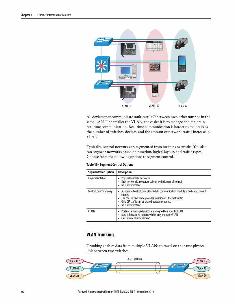
Chapter 3 Ethernet Infrastructure Features
All devices that communicate multicast I/O between each other must be in the same LAN. The smaller the VLAN, the easier it is to manage and maintain real-time communication. Real-time communication is harder to maintain as the number of switches, devices, and the amount of network traffic increase in a LAN.
Typically, control networks are segmented from business networks. You also can segment networks based on function, logical layout, and traffic types. Choose from the following options to segment control.
VLAN Trunking
Trunking enables data from multiple VLANs to travel on the same physical link between two switches.
VLAN 10 VLAN 102 VLAN 42
Table 10 - Segment Control Options
Segmentation Option Description
Physical isolation • Physically isolate networks• Each network is a separate subnet with clusters of control• No IT involvement
ControlLogix® gateway • A separate ControlLogix EtherNet/IP communication module is dedicated to each subnet
• The chassis backplane provides isolation of Ethernet traffic• Only CIP traffic can be shared between subnets • No IT involvement
VLANs • Ports on a managed switch are assigned to a specific VLAN• Data is forwarded to ports within only the same VLAN• Can require IT involvement
802.1 Q TrunkVLAN 102
VLAN 42
VLAN 20
VLAN 102
VLAN 42
VLAN 20
66 Rockwell Automation Publication ENET-RM002D-EN-P - December 2019

Ethernet Infrastructure Features Chapter 3
VLANs and Segmentation Guidelines
Follow these best practices:
• Configure separate VLANs for different work cells or areas of your plant.
• Configure one VLAN for all data traffic relevant to one particular area or cell zone. Because 80…90% of traffic is local to one cell, this is the optimal design.
• All devices with multicast connections must be on the same VLAN. Within a VLAN, multicast and unicast traffic can be mixed depending on application requirements.
• The default communication type of unicast must be used for point-to-point communication to minimize device, network, and infrastructure loading.
• Design small cell or area zones, each with a dedicated VLAN and IP subnet.
• Restrict data flow out of the cell or area zone unless plant-wide operations explicitly require it.
• Segment traffic types into VLANs and IP subnets for better traffic and security management.
• Use Layer 3 distribution switches to route information between cell or area zone VLANs and plant-wide operations in the industrial zone.
• Enable IP directed broadcast on cell or area zone VLANs with EtherNet/IP traffic to simplify configuration and maintenance from control systems, such as Linx-based software.
• Avoid large Layer 2 networks to simplify network management.
VLAN Trunking Protocol (VTP) VLAN Trunk Protocol (VTP) reduces administration and minimizes misconfiguration in a switched network. When you configure a new VLAN on one VTP server, the VLAN is distributed through all switches in the domain. VTP avoids the need to configure the same VLAN on multiple switches in a network.
IMPORTANT Use VTP with caution. If a new switch with a higher VTP revision number is added to the LAN, VLAN information is overwritten in all switches.
Rockwell Automation Publication ENET-RM002D-EN-P - December 2019 67

Chapter 3 Ethernet Infrastructure Features
Notes:
68 Rockwell Automation Publication ENET-RM002D-EN-P - December 2019

Appendix A
EtherNet/IP Protocol
EtherNet/IP™ protocol is a multi-discipline, control and information platform for industrial environments and time-critical applications. EtherNet/IP uses standard Ethernet and TCP/IP technologies and an open, application-layer protocol called the Common Industrial Protocol (CIP™).
The EtherNet/IP protocol follows these standards:• IEEE 802.3—Standard Ethernet, Precision Time Protocol (IEEE-1588)• IETF—Internet Engineering Task Force, standard Internet Protocol (IP)• IEC—International Electrotechnical Commission • ODVA—Open DeviceNet Vendor Association, Common Industrial
Protocol (CIP)
Topic Page
Common Industrial Protocol (CIP) 70
Connections 70
Packets Rate Capacity 75
Messaging 76
Application
Presentation
Session
Transport
Network
Link
Physical
CIP
Control and Information
Protocol
Ethernet
MAC
Ethernet
Physical
UDP TCP
IPIP-Multicast
EN50170
Control International
and
IF C 61158 Standard
Request for Comments
IETF
UDP/TCP/IP
IEEE 802.3
OP
EN
Rockwell Automation Publication ENET-RM002D-EN-P - December 2019 69
Appendix A EtherNet/IP Protocol
Common Industrial Protocol (CIP)
CIP is a messaging protocol for devices in industrial automation control systems. CIP is the application layer for the EtherNet/IP network. This protocol implements a relative path to send a message from the producing modules in a system to the consuming modules.
CIP uses the Producer/Consumer networking model instead of a source/destination (master/slave) model. The Producer/Consumer model reduces network traffic and increases speed of transmission.
In traditional I/O systems, controllers poll input modules to obtain their input status. In the CIP system, digital input modules are not polled by a controller. Instead, they produce their data either upon a change of state (COS) or at a requested packet interval (RPI). The frequency of update depends upon the options that are chosen during configuration and where on the network the input module resides. The input module, therefore, is a producer of input data and the controller is a consumer of the data.
The controller can also produce data for other controllers to consume. The produced and consumed data is accessible by multiple controllers over the Logix backplane and over the EtherNet/IP network. This data exchange conforms to the Producer/Consumer model.
Connections EtherNet/IP communication modules must consider connections and Ethernet nodes to communicate on the EtherNet/IP network.
A connection is a point-to-point communication mechanism that is used to transfer data between a transmitter and a receiver. Connections can be logical or physical.
Two connection types--TCP connections and CIP connections--are layered over each other each time data is transferred. The TCP connection is the first connection established. It is used for all EtherNet/IP communication and is required for all CIP connection use. One TCP connection supports multiple CIP connections and remains open.
Established over TCP connections, EtherNet/IP CIP connections transfer data from an application running on one end-node (transmitter) to an application running on another end-node (receiver). CIP connections are configured to use explicit or implicit message types. The message types support connected and unconnected connection types. Typically, connected CIP messages are used to transfer data. Unconnected CIP messages are used, but they are only temporary.
70 Rockwell Automation Publication ENET-RM002D-EN-P - December 2019

EtherNet/IP Protocol Appendix A
The following graphic shows how connections are layered on each other when data is transferred over the EtherNet/IP network.
Remember these points when configuring your EtherNet/IP network application:
• All connections are used each time data is transferred on the EtherNet/IP network.
• You specify CIP connection message types and CIP connection types when configuring your application.
For example, when a Logix5000 controller sends an MSG instruction to another Logix5000 controller, the transmitter sends the instruction to the receiver over a connection. That connection includes the following:– A TCP connection is established.– A CIP connection is layered on the TCP connection.– An explicit or implicit CIP connection message is delivered via the CIP
connection.– If an explicit message type is used, it can be connected or unconnected.
If an implicit message type is used, it is connected.
• Each EtherNet/IP communication module has TCP and CIP connection limits that you must account for when configuring your application.
TCP Connection
CIP Connection
Explicit Implicit
CIP Connection Message Types
Connected Connected
CIP Connection Types
Unconnected
You do not execute any tasks to establish these connections.
Your decisions when configuring your application determine the parameters of these connections.
Rockwell Automation Publication ENET-RM002D-EN-P - December 2019 71

Appendix A EtherNet/IP Protocol
These example applications describe how connections are used.
Terminology
The terms in this table help you understand connections.
EXAMPLE I/O ConnectionsA Logix5000 controller has five CIP I/O connections to modules in a remote chassis and all of these connections are through the same local 1756-EN2T module and the same remote 1756-EN2T module. The following connections exist:• One TCP connection• Five CIP connections
EXAMPLE RSLinx OPC Test ClientThe following connections exist:• One TCP connection• Four CIP connections (four is the default)
Table 11 - EtherNet/IP Connection Terminology
Term Definition
Producer and consumer
Producer/Consumer refers to implicit connections. With implicit connections, messages are sent cyclically (every RPI).EXAMPLE: Assume a ControlLogix™ controller is controlling one rack of FLEX I/O with a rack connection. Both the ENBT module that is local to the controller and the FLEX AENT module are consumers and producers of data. The AENT consumes outputs and produces inputs.
Client and server Client/server refers to explicit connections. A client creates a connection and initiates messages. A server provides a service or data. Clients can send messages continuously or intermittently.EXAMPLE: A ControlLogix controller can send an MSG instruction to another controller.
Transports Each connection has transports. A transport is a uni-directional entity with its own numeric identifier. An implicit connection has 2 transports. An explicit connection has 1 transport. Transports are important because they help you calculate the number of packets per second for each Ethernet interface.EXAMPLE: I/O For an I/O connection to a rack of distributed I/O, a connection is configured in the Logix Designer application by adding the communication adapter and I/O modules in the I/O list. When the connection is created, output packets flow from the controller to the I/O rack. In addition, input packets flow from the I/O to the controller. Each direction of flow is a transport. In this example, two transports exist. One transport is from the controller to the adapter. The second transport is from the adapter to the controller.EXAMPLE: Produced TagFor a multicast produced tag connection with two consumers, there is a connection to each consumer. Data from the producer is produced to the wire on one transport. Each of the consumers returns a heartbeat. A total of three transports exist in this example. One transport is from the tag producing controller to the ‘wire’ media. The second transport is from one consumer to the tag producer. The third transport is from the second consumer.
UCMM In the web servers, you can see references to Unconnected Message Manager (UCMM). This type of messaging is momentary and therefore can be ignored unless you are troubleshooting. Examples of where UCMM messages are used are:• Update of module firmware• Some functions in RSLinx software• CIP Generic MSG instruction• Opening any CIP connection (forward_open command)
72 Rockwell Automation Publication ENET-RM002D-EN-P - December 2019

EtherNet/IP Protocol Appendix A
TCP Connections
TCP connections are used for all EtherNet/IP communication and are established before one device on the network transmits data to one or more devices on the network. EtherNet/IP communication modules use one TCP connection for each IP address to which the module is connected.
TCP connections are automatically established before CIP connections because you can establish CIP connections only over a TCP connection. One TCP connection supports multiple CIP connections.
CIP Connections
CIP connections are automatically established over a TCP connection and transfer data from one device on the EtherNet/IP network to another. The following are examples of CIP connections:
• Logix5000 controller message transfer to Logix5000 controller• I/O or produced tag• Program upload• RSLinx DDE/OPC client• PanelView polling of a Logix5000 controller
There are different CIP connections.
IMPORTANT EtherNet/IP communication modules also have web servers that use TCP connections for non-CIP traffic, such as HTTP. However, TCP connections that are used for non-CIP traffic do not count against the limits.
Table 12 - CIP Connections
CIP Connection Description
Bridged A bridged connection is a connection that passes through the EtherNet/IP communication module. The endpoint of the connection is a module other than the EtherNet/IP communication module.EXAMPLE: An explicit connection from a controller through a 1756-EN2T module to another controller.
End-node An end-node connection is a connection whose endpoint is the EtherNet/IP communication module itself.EXAMPLE: An explicit connection from RSLinx software to the EtherNet/IP communication module to set the IP address of the module.
Rack-optimized A rack-optimized connection is an implicit message connection to a rack or assembly object in the EtherNet/IP communication module. Data from selected I/O modules is collected and produced on one connection (the rack-optimized connection) rather than on a separate direct connection for each module.This CIP connection is available with only digital I/O modules.
Direct An implicit message connection from a controller to a specific I/O module (as opposed to a rack-optimized connection).This CIP connection is available with analog and digital I/O modules.
Rockwell Automation Publication ENET-RM002D-EN-P - December 2019 73

Appendix A EtherNet/IP Protocol
CIP connections are further defined by these connection parameters:• CIP Connection Message Types• CIP Connection Types
CIP Connection Message Types
CIP connections use one of the following CIP connection message types:• Implicit• Explicit
Implicit connections are time critical in nature. This includes I/O and produced/consumed tags. Implicit refers to information (such as source address, data type, or destination address) that is implied in the message but not contained in the message.
Explicit connections are non-time critical and are request/reply in nature. Executing an MSG instruction or executing a program upload are examples of explicit connections. Explicit refers to basic information (such as source address, data type, or destination address) that is included in every message.
CIP Connection Types
CIP connection types determine how CIP connections transfer data on the network. The CIP connection types determine whether a connection is established between devices. If a connection is established between devices, the connection type determines if that connection remains open after data is transferred.
There are two CIP connection types:• Connected—Available with both implicit and explicit messages.• Unconnected—Available with only explicit messages.
74 Rockwell Automation Publication ENET-RM002D-EN-P - December 2019

EtherNet/IP Protocol Appendix A
Table 13 describes how CIP connections are used with implicit and explicit messages.
Packets Rate Capacity Connection size impacts an increased packet rate capacity that is obtained with firmware revision 3.xxx or later for ControlLogix EtherNet/IP communication modules.
Smaller connections are processed faster than larger connections. Larger connections can affect the increased packet rate capacity that is obtained with firmware revision 3.x or later. These types of applications use larger connections:
• Applications with rack-optimized connections• Applications with Integrated Motion on the EtherNet/IP network• Applications with large produce/consume tag arrays
Modules with firmware revision 3.xxx or later always have greater packet rate capacity than modules with firmware revision 2.x or earlier in the same application. Larger connections impact only how much greater the packet rate capacity is with firmware revision 3.x or later.
Some EtherNet/IP communication modules offer webpages that show module and application information. To view information, type the IP address of the module into your web browser.
Table 13 - CIP Connections with Implicit and Explicit Messages
CIP Connection Type As Used with Implicit Messages As Used with Explicit Messages
Connected The following events occur:1. A connection is established between devices.2. Data is transferred between devices.3. The connection remains open for future data transmission.The following are examples of connected implicit messaging:• I/O data transfer• Produced/consumed tags between Logix5000 controllersKeep in mind the following points for connected implicit messaging:• Execution time is more efficient because the CIP connection between
devices does not need to be reopened for each data transfer.• EtherNet/IP communication modules support limited numbers of CIP
connections. Because this connection remains open all the time, there is one fewer CIP connection available for other data transfer through the module.
The following events occur:1. A connection is established between devices.2. Data is transferred between devices.3. The connection between the devices is closed.
If data must be transferred again between these same two devices, the connection must be reopened.
The following are examples of connected Explicit Messaging:• MSG instruction• RSLinx Classic software setting the IP address for an EtherNet/IP
communication moduleIf you select a cached connection, the connection is not closed at the end of the transaction.Keep in mind the following points for connected Explicit Messaging:• Execution time is less efficient because the CIP connection between
devices must be reopened for each data transfer.• EtherNet/IP communication modules support limited numbers of CIP
connections. Because this CIP connection is closed immediately after use, the CIP connection is immediately available for other data transfer through the module.
Unconnected N/A In unconnected Explicit Messaging, no connection is established between devices.Data is sent in a packet that includes destination identifier information in the data structure but does not have a dedicated connection.
Rockwell Automation Publication ENET-RM002D-EN-P - December 2019 75

Appendix A EtherNet/IP Protocol
Messaging The EtherNet/IP network supports both time-critical (implicit) and non time-critical (explicit) message transfer services of CIP. Exchange of time-critical messages is based on the Producer/Consumer model where a transmitting device produces data on the network and many receiving devices can consume this data simultaneously.
Implicit Messages
Implicit messages are time critical in nature. This includes I/O and produced/consumed tags. Implicit refers to information (source address, data type, and destination address) that is implied in the message, but not contained in the message. Examples of implicit applications include the following:
• Real-time I/O data• Functional safety data• Motion control data
Implicit messages use the User Datagram Protocol (UDP) and can be unicast or multicast. Implicit messages transport data via transport class 0/1 (Class 1):
• The data source/destination is an application object (assembly object).• There is no protocol in the message data—it is all I/O data.• Data transfer is more efficient because the meaning of the data is known
ahead of time.• Transfer is initiated on a time basis (cyclic trigger) or requested packet
interval (RPI).• There is a connection timing mechanism to alert the application if the
other side has stopped communicating.• Messaging is always connected—there is no unconnected implicit
messaging.
An implicit message times out in controller_multiplier x RPI. The multiplier is selected by the controller firmware so that the timeout is greater than or equal to 100 ms. The minimum multiplier is 4.
These are examples:• RPI = 2 ms; controller multiplier = 64. The timeout is 128 ms.• RPI = 10 ms; controller multiplier = 16. The timeout is 160 ms.
76 Rockwell Automation Publication ENET-RM002D-EN-P - December 2019

EtherNet/IP Protocol Appendix A
Explicit Messages
Explicit messages are non-time critical and are request/reply in nature. Executing an MSG instruction or executing a program upload are examples of explicit connections. Explicit refers to basic information (such as source address, data type, or destination address) that is included in every message. Each request is typically directed at another data item. Examples of explicit applications include the following:
• HMI• RSLinx connections• Message (MSG) instructions• Program upload/download
Explicit messages use Transmission Control Protocol (TCP). Explicit messages are used for point-to-point, client-server transactions that use transport class 3 (Class 3):
• The server side is bound to the Message Router object and has access to all internal resources.
• The client side is bound to a client application object and must generate requests to the server.
• Explicit messages use an Explicit Messaging protocol in the data portion of the message packet.
• Explicit messages can be connected or unconnected.
An explicit message times out in 30 seconds. This is user-changeable in the Message (MSG) instruction structure.
Application
Object
Explicit
Messaging
Connection
Request
ResponseApplication
Object
Explicit
Messaging
Connection
Request
Response
Device #1 Device #2
Rockwell Automation Publication ENET-RM002D-EN-P - December 2019 77

Appendix A EtherNet/IP Protocol
Notes:
78 Rockwell Automation Publication ENET-RM002D-EN-P - December 2019

Index
AAAA 32access control entry. See ACEaccess control list. See ACLaccounting 33ACE 35ACL 35address
dynamic secure MAC 44gateway 13gateway default 13static secure MAC 44
address limit, multicast 18Address Resolution Protocol. See ARPalternate port 53ARP 14assign IP address 10authentication 32Authentication, Authorization, and
Accounting. See AAAauthorization 32autonegotiation 28
BBest Master Clock Algorithm. See BMCAblocked port 53BMCA 50boundary clock 47bridge
media 25broadcast 16broadcast message 14, 16
CCA Trustpoints 36capacity
packet rate 75CDP 46CIP
connections 73types 74
CIP data 78CIP Syncclient and server 72clock modes 50clock types, PTP 47clock, master 50commission devices 10communincation protocols 14components
Ethernet infrastructure 21configuration requirements 10
connections 70CIP 73direct 73TCP 73
consumer 72converters, media 25
DDAN 44default gateway address 13delays, packet 48Device Level Ring. See DLRDHCP 37DHCP for ring devices 11DHCP IP address 11direct connections 73DLR 19, 23, 36DLR DHCP 11DNS 15domain name system. See DNSdouble attached node. See DANDynamic Host Configuration Protocol. See
DHCPdynamic secure MAC 44
EEtherChannels 19, 40, 41Ethernet
infrastructure 21media 24topologies 22
EtherNet/IP networkoverview 69
explicitconnections 74messages 77
Ffast convergence 56Flex Links 19, 38frames 17full-duplex 28
Ggateway address 13gateways, redundant 36Grandmaster clock 47
Hhalf-duplex 28high priority PoE ports 46
Rockwell Automation Publication ENET-RM002D-EN-P - December 2019 79

Index
IIEC 62439-3 44IEEE 802.1D 62IEEE 802.1Q 59IEEE 802.3 46IGMP 39IGMP snooping with querier 39implicit
connections 74messages 76
infrastructure components 21infrastructure switch 44Internet Group Management Protocol. See
IGMPIP address assignment 10IP address format 10IP address, DHCP 11IP address, static 11
LLAN A 44LAN B 44latency, network 48linear topology 22, 23load balancing 56logical interfaces 40loopback interfaces 40, 42low priority PoE ports 46
MMAC ID 44managed switches 27management information base. See MIBmask, subnet 12master clock, PTP 50media
bridge 25converters 25Ethernet 24routers 26switches 27
messagesexplicit 77implicit 76PTP 48types 74
MIB 61modes
full-duplex 28half-duplex 28PTP clock 50
MSTP 19multicast 16, 17multicast address limit 18
Nnetwork
protocols 9network convergence 19network latency 48nodes
ring 36
Oopen segment, REP 53ordinary clock 47overview
EtherNet/IP network 69
Ppackets 16
rate capacity 75Parallel Redundancy Protocol. See PRPPoE 46port channels 19, 40, 41port mirroring 63port security 44PortFast 59power budget 46Power over Ethernet. See PoEPrecision Time Protocol. See PTPprioritize traffic 51protocols
Address Resolution Protocolcommunication 14DHCP 37Flex Links 38IGMPnetwork 9PRPPTPREPresiliency 19STPtransmission 14VTP
PRP 44PTP 47PTP clock modes 50PVST+ 19
QQoS 51, 52Quality of Service. See QoSquerier, IGMP snooping 39
RRADIUS server 33recovery, ring 52
80 Rockwell Automation Publication ENET-RM002D-EN-P - December 2019

Index
RedBox 44Redundancy box. See RedBoxredundant gateways 36redundant star topology 22REP 19, 52, 55
requirements and restrictions 59segment 59Telnet 59
resiliency 19protocols 19REP 52
Resilient Ethernet Protocol. See REPring nodes 36ring participant 36ring recovery 52ring supervisor 36ring topology 22routers
media 26RSTP 19
SSAN 44security violations 45security, port 44segment, REP 59segmentation 65, 67segments, REP 52, 53, 54server
DHCP 37DNS
Simple Network Management Protocol. See SNMP
single attached node. See SANSNMP 61SNMPv3 61SPAN 63Spanning Tree Protocol. See STPstar topology 22static IP address 11static secure MAC address 44STP 19, 41subnet mask 12supervisor, ring 36switch, infrastructure 44Switched Port Analyzer. See SPANswitches
managed 27media 27unmanaged 27
TTACACS+ server 33TCP connections 73Telnet 59
terminology 72time, CIP Synctopologies
DLR 23linear 22, 23redundant star 22ring 22
traffic priority 51traffic types 16transmission packets 16transmission protocols 14transparent clock 47transports 72trunk port 59trunking, VLAN 66
UUCMM 72unicast 16unmanaged switches 27
VVDAN 44violations, security 45virtual double attached node. See VDANvirtual local area network. See VLANVLAN 64, 66VLAN load balancing 56VLAN segmentation 65, 67VLAN trunking 66VLAN Trunking Protocol. See VTPVTP 67
Rockwell Automation Publication ENET-RM002D-EN-P - December 2019 81

Index
Notes:
82 Rockwell Automation Publication ENET-RM002D-EN-P - December 2019


Publication ENET-RM002D-EN-P - December 2019Supersedes Publication ENET-RM002C-EN-P - May 2013 Copyright © 2019 Rockwell Automation, Inc. All rights reserved. Printed in the U.S.A.
Rockwell Automation Support
Use the following resources to access support information.
Documentation Feedback
Your comments will help us serve your documentation needs better. If you have any suggestions on how to improve this document, complete the How Are We Doing? form at http://literature.rockwellautomation.com/idc/groups/literature/documents/du/ra-du002_-en-e.pdf.
Technical Support Center Knowledgebase Articles, How-to Videos, FAQs, Chat, User Forums, and Product Notification Updates.
https://rockwellautomation.custhelp.com/
Local Technical Support Phone Numbers
Locate the phone number for your country. http://www.rockwellautomation.com/global/support/get-support-now.page
Direct Dial Codes Find the Direct Dial Code for your product. Use the code to route your call directly to a technical support engineer.
http://www.rockwellautomation.com/global/support/direct-dial.page
Literature Library Installation Instructions, Manuals, Brochures, and Technical Data.
http://www.rockwellautomation.com/global/literature-library/overview.page
Product Compatibility and Download Center (PCDC)
Get help determining how products interact, check features and capabilities, and find associated firmware.
http://www.rockwellautomation.com/global/support/pcdc.page
.
Rockwell Otomasyon Ticaret A.Ş., Kar Plaza İş Merkezi E Blok Kat:6 34752 İçerenköy, İstanbul, Tel: +90 (216) 5698400
Rockwell Automation maintains current product environmental information on its website at http://www.rockwellautomation.com/rockwellautomation/about-us/sustainability-ethics/product-environmental-compliance.page.
Allen-Bradley, ArmorStratix, ControlLogix, Integrated Architecture, Logix 5000, POINT I/O, PowerFlex, Rockwell Automation, Rockwell Software, and Stratix are trademarks of Rockwell Automation, Inc.
CIP, CIP Sync, ControlNet, DeviceNet, and EtherNet/IP are trademarks of ODVA, Inc.
Catalyst, Cisco, and Cisco Systems are trademarks of Cisco Systems, Inc.
Trademarks not belonging to Rockwell Automation are property of their respective companies.