eta 20/0932 european technical date of issue: 2020-12-18
TRANSCRIPT

European Organisation
for Technical Assessment
European Technical
Assessment
ETA 20/0932 Version 01
Date of issue: 2020-12-18
UBAtc Assessment Operator:
Belgian Construction Certification Association
Rue d’Arlon 53 - 1040 Brussels
www.bcca.be - [email protected]
Technical Assessment Body issuing the European Technical Assessment: UBAtc.
UBAtc has been designated according to Article 29 of Regulation (EU) No 305/2011
and is member of EOTA (European Organisation for Technical Assessment)
Trade name of the
construction product: PROMATECT® 100X
Product family to which the
construction product belongs: Fire Protective board
Manufacturer:
ETEX BUILDING PERFORMANCE NV
Bormstraat 24
B-2830 Tisselt (Belgium)
Manufacturing plant(s): ETEX BUILDING PERFORMANCE production plant 07
Website: www.promat-international.com
This European Technical
Assessment is issued in
accordance with Regulation
(EU) No 305/2011, on the
basis of:
European Assessment Document (EAD):
EAD 350142-00-1106
This European Technical
Assessment contains: 39 pages, including 2 annexes, which form an integral part
of the document.

ETA 20/0932 - 2/39
Legal bases and general conditions
1 This European Technical Assessment is issued by UBAtc
(Union belge pour l'Agrément technique de la
construction, i.e. Belgian Union for technical Approval in
construction), in accordance with:
− Regulation (EU) No 305/2011 (1) of the European
Parliament and of the Council of 9 March 2011 laying
down harmonised conditions for the marketing of
construction products and repealing Council
Directive 89/106/EEC
− Commission Implementing Regulation (EU) No
1062/2013 (2) of 30 October 2013 on the format of the
European Technical Assessment for construction
products
− European Assessment Document:
EAD 3501-42-00-1106 (2017) : Fire protective products
- Fire protective board, slabs and mat products and
kits.
2 Under the provisions of Regulation (EU) No 305/2011, UBAtc
is not authorized to check whether the provisions of this
European Technical Assessment are met once the ETA has
been issued.
3 The responsibility for the conformity of the performances of
the products with this European Technical Assessment and
the suitability of the products for the intended use remains
with the holder of the European Technical Assessment.
4 Depending on the applicable Assessment and verification
of constancy of performance (AVCP) system, (a) notified
body(ies) may carry out third-party tasks in the process of
assessment and verification of constancy of performance
under this Regulation once the European Technical
Assessment has been issued.
5 This European Technical Assessment allows the
manufacturer of the construction product covered by this
ETA to draw up a declaration of performance for the
construction product.
6 CE marking should be affixed to all construction products
for which the manufacturer has drawn up a declaration of
performance.
7 This European Technical Assessment is not to be transferred
to other manufacturers, agents of manufacturers, or
manufacturing plants other than those indicated on
page 1 of this European Technical Assessment.
8 The European Technical Assessment holder confirms to
guarantee that the product(-s) to which this assessment
relates, is/are produced and marketed in accordance with
and comply with all applicable legal and regulatory
provisions, including, without limitation, national and
European legislation on the safety of products and services.
The ETA-holder shall notify the UBAtc immediately in writing
of any circumstance affecting the aforementioned
guarantee. This assessment is issued under the condition
that the aforementioned guarantee by the ETA-holder will
be continuously observed.
(1): OJEU, L 88 of 2011/04/04
9 According to Article 11(6) of Regulation (EU) No 305/2011,
when making a construction product available on the
market, the manufacturer shall ensure that the product is
accompanied by instructions and safety information in a
language determined by the Member State concerned
which can be easily understood by users. These instructions
and safety information should fully correspond with the
technical information about the product and its intended
use, which the manufacturer has submitted to the
responsible Technical Assessment Body for the issuing of the
European Technical Assessment.
10 Pursuant to Article 11(3) of Regulation (EU) No 305/2011,
manufacturers shall adequately take into account
changes in the product-type and in the applicable
harmonised technical specifications. Therefore, when the
contents of the issued European Technical Assessment do
not any longer correspond to the product-type, the
manufacturer should refrain from using this European
Technical Assessment as the basis for their declaration of
performance.
11 All rights of exploitation in any form and by any means of
this European Technical Assessment is reserved for UBAtc
and the ETA-holder, subject to the provisions of the
applicable UBAtc regulations.
12 Reproduction of this European Technical Assessment
including transmission by electronic means shall be in full.
However, partial reproduction can be made with the
written consent of UBAtc. In this case partial reproduction
has to be designated as such. Texts and drawings of
advertising brochures shall not contradict or misuse the
European Technical Assessment.
13 Subject to the application introduced, this European
Technical Assessment is issued in English and may be issued
by the UBAtc in its official languages. The translations
correspond fully to the English reference version circulated
in EOTA.
14 This European Technical assessment was first issued by
UBAtc on 18 December 2020.
(2): OJEU, L 289 of 2013/10/31

ETA 20/0932 - 3/39
Technical Provisions
1 Technical description of the product
1.1 General
PROMATECT® 100X is a non-combustible fire protective board,
based on the PromaX® technology. It is made of aerated
calcium sulphate di-hydrate, reinforcing glass fibres, functional
additives, calcium silicate fillers and water. It is specifically
designed for fire compartmentation in buildings, such as
partitions and ceilings, when high fire protection performance
is required.
PROMATECT® 100X has smooth surface finishes on the front and
back sides. The front and back sides of the board are coloured
blue. The board is printed on its side. The board exhibits square
or tapered edges on its longitudinal sides and square edges on
its transversal sides.
PROMATECT® 100X is manufactured at ETEX BUILDING
PERFORMANCE plant 07 (known at UBAtc).
1.2 Dimensions and density
Dimensions and density of the boards are given in Table 1.
Table 1 : Dimensions and density PROMATECT® 100X
(EN 12467)
Apparent density: 840 kg/m³ ± 10%
Thickness Tolerance on
thickness Length x width
Tolerances on
length and
width
(mm) (mm) (mm) (mm)
12 0 / +1 2500 x 1200
2000 x 1200 -5/+0
20 0 / +2
The tolerance on the squareness is +/-1,5 mm/m.
Other dimensions (length), smaller than the above, are
available on request.
1.3 Ancillary products
Ancillary products referred to in this ETA, as a part of installation
provisions or in the framework of determining performances
(e.g. fire resistance test), are not covered by this ETA and may
not be CE-marked based on it.
2 Specification of the intended use(s) in
accordance with the applicable EAD
2.1 Intended uses
This ETA covers fire protective PROMATECT® 100X intended for :
− Internal use (EAD 350142-00-1106, type Z2).
− Internal and semi-exposed use (EAD 350142-00-1106,
Type Y)
PROMATECT® 100X is intended to protect elements or to be
used in assemblies as specified in Table 2.
Table 2: Intended use
Protection of
EAD
350142-00-1106
reference
Horizontal membrane protection incl.
suspended ceilings acc. to EN 13964 Type 1
Vertical membrane protection Type 2
Load-bearing concrete elements Type 3
Load-bearing steel elements Type 4
Load-bearing flat concrete profiled sheet
composite elements Type 5
Load-bearing concrete filled hollow steel
columns Type 6
Load-bearing timber elements Type 7
Fire separating assemblies with no load-
bearing requirements Type 8
Technical services assemblies in buildings Type 9
Uses not covered by types 1-9 Type 10
Table 2 shows the possible intended uses of the boards. Not all
of these have been assessed in the framework of this ETA with
regard to fire resistance performance. Annex II of this ETA shows
a list of the uses for which fire resistance assessment was carried
out. This ETA covers assemblies installed in accordance with the
provisions given in Annex II of this ETA.
With regard to fire resistance performance, the other intended
uses may be supported by other means at national level (as
specified in the note in paragraph 3.2.2 of this ETA).
The provisions made in this European Technical Assessment are
based on an assumed intended working life of 25 years,
provided that the assembled product is subject to appropriate
use and maintenance, in accordance with this ETA.
Indications given regarding the working life may not be
interpreted as a guarantee given by the producer or the
UBAtc, but shall be regarded only as a means for choosing the
appropriate product(s) in relation to the expected
economically reasonable working life of the construction
works.

ETA 20/0932 - 4/39
2.2 Assumptions
2.2.1 Manufacturing directives
This European Technical Assessment is issued for
PROMATECT® 100X boards on the basis of agreed
data/information, deposited with the UBAtc, which identifies
the product that has been assessed. Changes to the
product/production process, which could result in the
deposited data/information being incorrect should be notified
to the UBAtc before the changes are introduced.
Raw materials are mixed in a continuous procedure to form a
slurry. This slurry is poured on a fibreglass liner and covered by
a second liner. The products pass through some rolls to form a
long continuous board with the required thickness and width.
The first hardening of the slurry occurs while the boards move
over the continuous belt. When the boards have sufficiently
hardened, the boards are cut to the required length. An
identification is printed on each individual board. The boards
pass through an oven for curing and drying.
2.2.2 Installation
2.2.2.1 Supporting structure
The distance between supports shall be in accordance with
the information provided in the assemblies described in Annex
II of this ETA.
2.2.2.2 Cutting and machining
The fire protective PROMATECT® 100X boards shall be cut using
the ‘score and snap’ method as used with plasterboards. No
power tools are required to cut the board. When machining
the fire protective board, dust extraction shall take place and
inhalation of dust shall be avoided.
A safety data sheet is available from the manufacturer upon
request.
2.2.2.3 Joints
The realisation of joints between adjacent boards and the use
and type of joint filler shall be in accordance with the
assemblies described in Annex II of this ETA.
2.2.2.4 Mechanical fasteners
Fastening of PROMATECT® 100X boards onto the support
structure shall be in accordance with the assembly information
provided in Annex II of this ETA.
In the case multiple layers are used, each layer of boards is
fixed to the supporting structure through the other layer(s), the
joints of each layer offset by 500 mm in relation to (the) other
layer(s).
2.2.2.5 Surface treatment
The PROMATECT® 100X board surface allows for most types of
decoration. When applying a surface treatment, the
absorption capacity and alkalinity of the boards have to be
taken into account.
Assessment of the influence of surface treatment (such as
plastering, painting, tiling, application of wallpaper), on the
performance of the PROMATECT® 100X boards, has not been
performed in the framework of this ETA.
2.2.2.6 Assembly
The PROMATECT® 100X boards shall be applied as specified in
the assemblies presented in Annex II of this ETA.
2.3 Recommendations
2.3.1 Recommendations on packaging, transport and
storage
The boards are delivered on pallets.
PROMATECT®-100X boards shall be horizontally stacked on a
flat surface, in a dry and well-ventilated space.
The boards shall always be manipulated from the stack by 2
persons and then be transported vertically.
2.3.2 Recommendations on use, maintenance and repair
Future modifications to the building should not adversely affect
the fire protective properties of the system in which
PROMATECT® 100X boards are used. Care should be taken to
prevent any reduction of fire performance as a result of
increased applied load to protected elements of the works
(e.g. beams, columns, ceilings, floors, or walls).
The assessment is based on the assumption that damage, for
example caused by accidental impact, is repaired. It is further
assumed that replacement of components during
maintenance/repair will be undertaken using materials
specified by the ETA.

ETA 20/0932 - 5/39
3 Performance of the product and references to
the methods used for its assessment
3.1 Mechanical resistance and stability (BWR1)
This basic requirement for construction works is not relevant for
PROMATECT® 100X boards according to EAD 350142-00-1106.
3.2 Safety in case of Fire (BWR2)
3.2.1 Reaction to fire
PROMATECT® 100X boards have a reaction to fire classification
A1 according to EN 13501-1.
3.2.2 Fire resistance
Assemblies incorporating PROMATECT® 100X boards have a
resistance to fire classification according to EN 13501-2 as
presented in Annex II of this ETA.
The tested assemblies, as presented in Annex II of this ETA, have
a fire resistance classification of respectively
− EI120 for a vertical non-loadbearing separating
element on metal frame with a cladding made of 2
layers of 20 mm PROMATECT® 100X, and including
two inspection hatches,
− EI120 for a vertical non-loadbearing element made
of a lining of one layer of 12 mm PROMATECT® 100X
directly fixed to a plastered hollow-clay-masonry-unit
wall and
− EI120 (a←b) for a horizontal non-loadbearing
separating element, i.e. a suspended ceiling on
metal frame with a membrane made of 2 layers of
20 mm PROMATECT® 100X, including a luminaire,
inspection hatches and pipe penetration.
NOTE: In accordance with EAD 350142-00-1106, until 10 years
after the initial issuing of this ETA, or until the withdrawal of
relevant national test and classification standards, CE-marking
will cover a limited number of assemblies subjected to fire
resistance assessment. As time progresses, the performance
declaration for fire resistance covered by CE-marking should
gradually be enlarged by the ETA-holder and incorporated in
this ETA by amendment or revision. In the meantime, and
taking into account the transitional arrangements for test and
classification standards and the corresponding national
legislation (see EC Guidance paper J), the ETA-holder shall be
permitted to maintain and be able to use - on a national basis
- his portfolio of test data for this characteristic, based on
relevant national standards, next to the performance
declaration covered by the CE-marking based on this ETA.
3.3 Hygiene, Health and the environment (BWR3)
3.3.1 Air and/or water permeability
No performance assessed.
3.3.2 Release of dangerous substances
No performance assessed.
3.4 Safety in Use (BWR4)
3.4.1 Flexural strength
When tested in accordance with EN 12467, the
PROMATECT® 100X boards have a longitudinal modulus of
rupture (MOR) greater than or equal to 4,5 MPa and a
transverse modulus of rupture (MOR) greater than or equal to
2,5 MPa.
The PROMATECT® 100X boards have sufficient flexural strength
to support their own mass. The PROMATECT® 100X boards are
not intended to support additional loads.
3.4.2 Dimensional stability
The dimensional stability has been determined in accordance
with EN 318. The dimensional stability for the length is:
− 65 % RH / 20 °C to 85 % RH / 20 °C:
• Longitudinal: 0,3 mm/m
• Transverse: 0,2 mm/m
− 65 % RH / 20 °C to 30 % RH / 20 °C:
• Longitudinal: -0,1 mm/m
• Transverse: -0,1 mm/m
The dimensional stability has been determined in accordance
with EN 318. The dimensional stability for the thickness is:
− 65 % RH / 20 °C to 85 % RH / 20 °C:
• Longitudinal: 0,2 %
• Transverse: 0,0 %
− 65 % RH / 20 °C to 30 % RH / 20 °C:
• Longitudinal: -0,1 %
• Transverse: -0,1
3.4.3 Resistance to impact and eccentric load
No performance assessed.
3.5 Energy economy and heat retention (BWR6)
3.5.1 Thermal conductivity
No performance assessed.
3.5.2 Water vapour permeability
No performance assessed.
3.6 Protection against noise (BWR5)
3.6.1 Airborne sound insulation
No performance assessed.
3.6.2 Sound absorption
No performance assessed.
3.6.3 Impact sound insulation
No performance assessed.
3.7 Aspects of durability, serviceability and identification
3.7.1 Durability and serviceability
3.7.1.1 Resistance to deterioration caused by water
This characteristic is not relevant for the intended use Z2
(internal use) and Y (semi exposed). No performance assessed.

ETA 20/0932 - 6/39
3.7.1.2 Resistance to soak/dry
This characteristic is not relevant for the intended use Z2
(internal use) and Y (semi exposed). No performance assessed.
3.7.1.3 Resistance to freeze/thaw
The resistance to freeze/thaw according to
EAD 3501 42 00 1106 was favourably assessed.
3.7.1.4 Resistance to heat/rain
This characteristic is not relevant for the intended use Z2
(internal use) and Y (semi exposed). No performance assessed.
3.7.1.5 Basic durability assessment
Product performances confirm a working life of 25 years for the
intended uses Z2 (internal use) and Y (Internal and semi-
exposed use).
3.7.2 Identification
3.7.2.1 Length, width (see Table 1)
The width of the PROMATECT® 100X boards is not greater than
1200 mm.
The length of the PROMATECT® 100X boards is not greater than
2500 mm. The standard length is 2000 mm or 2500 mm
3.7.2.2 Thickness (see Table 1)
The PROMATECT® 100X boards are available in thicknesses of
12 mm and 20 mm.
3.7.2.3 Dimensional tolerances (see Table 1)
The tolerances of the PROMATECT® 100X boards are
mentioned in table 1
3.7.2.4 Apparent density (see Table 1)
The apparent density has been determined in accordance
with EN 12467. The apparent density is 840 kg/m³ ± 10%.
3.7.2.5 Compressive strength
When tested in accordance with EAD 350142-00-1106 and
EN 789, the PROMATECT® 100X boards have a compressive
strength greater than or equal to 6,0 MPa.
This value is a guidance value, and does not reflect a statistical
evaluation, nor a minimum guaranteed value. This value is not
intended to be used as a calculation value as basis for
structural design.
3.7.2.6 Tensile strength
When tested in accordance with EAD 350142-00-1106 and
EN 319, the PROMATECT® 100X boards have a perpendicular
tensile strength greater than or equal to 0,9 MPa.
When tested in accordance with EAD 350142-00-1106 and
EN 789, the PROMATECT® 100X boards have a parallel tensile
strength greater than or equal to 1,6 MPa (longitudinal) ad
1,4 MPa (transverse).
These values are guidance values, and do not reflect a
statistical evaluation, nor minimum guaranteed values. These
values are not intended to be used as calculation values as
basis for structural design.

ETA 20/0932 - 7/39
4 Assessment and verification of constancy of
performance (AVCP) system applied, with
reference to its legal base
In accordance with Regulation (EU) N° 305/2011, Article 65,
Directive 89/106/EEC is repealed, but references to the
repealed Directive shall be construed as references to the
Regulation.
The system of assessment and verification of constancy of
performance, specified in the Decision of the Commission
1999/454/EC of 1999/06/22 (3), as amended, is specified in the
following Table.
Table 3 – System of assessment and verification of
constancy of performance applicable to
PROMATECT® 100X
Pro
du
ct(
s)
Inte
nd
ed
use
(s)
Lev
el(
s) o
r
cla
ss(e
s)
Ass
ess
me
nt
an
d
ve
rific
atio
n o
f
co
nst
an
cy
of
pe
rfo
rma
nc
e
syst
em
(s)*
Fire
Protective
Products
For fire
compartmentation
and/or fire protection
or fire performance
Any 1
* See Annex V to Regulation (EU) N° 305/2011
In addition, according to the decision 1999/454/EC of
1999/06/22 (3) of the European Commission, as amended,
the systems of assessment and verification of constancy of
performance specified in table 4 apply to fire protective
products with regard to reaction to fire, as amended, and
Commission Delegated Regulation (EU) 2016/364 of
2015/07/01 (4).
Table 4 – Systems of assessment and verification of
constancy of performance with respect to the reaction to
fire
Pro
du
ct(
s)
Inte
nd
ed
use
(s)
Lev
el(
s) o
r
cla
ss(e
s)
(re
ac
tio
n t
o fire
)
Ass
ess
me
nt
an
d
ve
rific
atio
n o
f
co
nst
an
cy
of
pe
rfo
rma
nc
e
syst
em
(s)a
Fire
Protective
Products
For uses
subject to
regulations on
reaction to fire
(A1, A2, B,
C)* 1
(A1, A2, B,
C)**, D, E, F 3
(A1 to F)*** ,
NPD**** 4
a Systems 1, 3 and 4 : See Regulation (EU) N° 305/2011, Annex V
* Products/materials for which a clearly identifiable stage in the
production process results in an improvement of the reaction
to fire classification (e.g. an addition of fire retardants or a
limiting of organic material)
** Products/materials not covered by footnote (*)
*** Products/materials that do not require to be tested for reaction
to fire (e.g. products/materials of class A1 according to
Commission Decision 96/603/EC5, as amended)
**** ‘No Performance Declared’ in accordance with Regulation (EU)
N° 305/2011, Article 6(f)a Systems1 and 2+ :See Regulation (EU) N°
305/2011, Annex V
(3): OJEU L178/52 of 1999/07/14 (4): OJEU L68/4 of 2016/03/15
5 Technical details necessary for the
implementation of the AVCP system, as
foreseen in EAD 350142-00-1106
5.1 Tasks for the ETA-holder
5.1.1 Factory production control (FPC)
The ETA-holder shall exercise permanent internal control of the
production. All the elements, requirements and provisions
adopted by the ETA-holder shall be documented in a
systematic manner in the form of written policies and
procedures. This factory production control system shall ensure
that production is in conformity with this ETA.
The personnel involved in the production process shall be
identified, sufficiently qualified and trained to operate and
maintain the production equipment. Machinery equipment
shall be regularly maintained, and this shall be documented.
All processes and procedures of production shall be recorded
at regular intervals.
The ETA-holder shall maintain a traceable documentation of
the production process from purchasing or delivery of raw or
basic raw materials up to the storage and delivery of finished
products.
The factory production control system for the product includes
relevant design specifications, including adequate drawings
and written instructions for:
− type and quality of all materials
− overall dimensions
− packaging and transport protection
The production control system shall specify how the control
measures are carried out, and at which frequencies.
ETA-holders which have an FPC system that complies with
EN ISO 9001 and that addresses the requirements of this ETA are
recognised as satisfying the FPC requirements.
Products that do not comply with requirements as specified in
the ETA shall be separated from the conforming products and
marked as such. The ETA-holder shall register non-compliant
production and action(-s) taken to prevent further non-
conformities. External complaints shall also be documented, as
well as actions taken.
When materials/products are delivered for incorporation into
the production process, verification of conformity with
specifications in the quality manual shall take place and be
recorded.
If supplied materials/components are not manufactured and
tested by the supplier in accordance with agreed methods, or
where the ETA-holder purchases materials/components on the
open market, then where appropriate, they shall be subject to
suitable documented checks/tests by the ETA-holder before
acceptance.
(5): OJEU L267 of 1996/10/19

ETA 20/0932 - 8/39
The characteristics of incoming material and components, for
which the supplier demonstrates documented compliance
with a product specification, for an intended use that is
appropriate for its use as a raw material or component of the
product, shall be considered satisfactory and need, except in
justified doubt, no further checking, unless the control plan
specifies differently.
5.1.2 Testing of samples taken at the factory
5.1.2.1 General
At least the following minimum information shall be recorded:
− date and time of manufacture
− type of product produced (boards)
− material specification (dimensions and thickness)
− all results of the verifications performed within the
agreed upon control plan
5.1.2.2 Maintenance, checking and calibration of equipment
All testing equipment shall be maintained, calibrated and/or
checked against equipment or test specimens traceable to
relevant international or nationally recognised reference test
specimens (standards). In case no such reference test
specimens exist, the basis used for internal checks and
calibration shall be documented.
The ETA-holder shall ensure that handling, preservation and
storage of test equipment is such that the performances are
maintained
When production is intermittent, the ETA-holder shall ensure
that any test equipment which may be affected by the
interruption is suitably checked and/or calibrated before use.
The calibration of all test equipment shall be repeated if any
repair or failure occurs which could upset the calibration of the
test equipment.
5.1.2.3 Testing as part of Factory Production Control
Table 5 specifies minimum requirements for testing as part
of FPC.
If constituent materials or components are supplied by other
manufacturers to the ETA-holder, the supplier shall perform FPC
on those constituent materials or components. If that is the
case, those suppliers should submit the relevant records to the
ETA-holder.
(6): A week represents 5 production days. (7): Production shall be subjected to a small oven test (test
performed on one thickness).
Table 5 : FPC test plan for PROMATECT® 100X
Property Minimum frequency
Determination of organic
content (reaction to fire) 1 per week (6)
Determination of dimensional
stability at high temperatures
(fire resistance)
1 per week
Indirect test method (small
oven test)7 1 per year
Dimensional stability 1 per year
Identification
length, width 1 per day (8), per dimension
thickness 1 per day, per thickness
apparent density 1 sample per n boards
Flexural strength 1 sample per n boards
5.2 Initial Type Testing
The assessment tests will have been conducted by the UBAtc
or under its responsibility (which may include a proportion
conducted by an independent laboratory or by the ETA-
applicant, witnessed by the UBAtc). The UBAtc will have
assessed the results of these tests in accordance with chapter 3
of this ETA, as part of the ETA issuing procedure.
The results of assessment testing shall be used by notified bodies
(cf. Regulation (EU) 305/2011, Annex V, clause 1.6).
6 Other marking and/or information
Each board shall at least be marked with product name and a
traceability code. Each package is marked with the product
name, traceability code, thickness of the boards, and
dimensions of the boards.
(8): A day represents a 24h time period in which production
is considered to be as usual for the production facility
concerned.

ETA 20/0932 - 9/39
UBAtc asbl is a non-profit organization according to Belgian law. It is a Technical Assessment Body notified by the Belgian
notifying authority, the Federal Public Services Economy, SMEs, Self-Employed and Energy, on 17 July 2013 in the framework
of Regulation (EU) No 305/2011 of the European Parliament and of the Council of 9 March 2011 laying down harmonised
conditions for the marketing of construction products and repealing Council Directive 89/106/EEC and is member of the
European Organisation for Technical Assessment, EOTA (www.eota.eu).
This European Technical Assessment has been issued by UBAtc asbl, in Sint-Stevens-Woluwe, on the basis of the technical work
carried out by the Assessment Operator, BCCA.
On behalf of UBAtc asbl,
On behalf of the Assessment Operator, BCCA,
responsible for the technical content of the
ETA,
Eric Winnepenninckx
secretary general
Benny De Blaere,
director
Olivier Delbrouck,
director general
The most recent version of this European Technical Assessment may be consulted on the UBAtc website (www.ubatc.be).

ETA 20/0932 - 10/39
Annexes
Annex I: References
Reference number EAD 350142-00-1106
Document title Fire protective products - Fire protective board,
slab and mat products and kits.
Reference number EN 13964:2004
Document title Suspended ceilings - Requirements and test
methods.
Reference number EN 13501-1:2002
Document title Fire classification of construction products and
building elements - Part 1: Classification using test data from
reaction to fire tests
Reference number EN 13501-2:2003
Document title Fire classification of construction products and
building elements - Part 2: Classification using data from fire
resistance tests, excluding ventilation services
Reference number EN 12467:2004
Document title Fibre-cement flat sheets - Product specification
and test methods
Reference number EN 318:2002
Document title Wood based panels - Determination of
dimensional changes associated with changes in relative
humidity
Reference number EN 826:1996
Document title Thermal insulating products for building
applications - Determination of compression behaviour
Reference number EN 1607:1996
Document title Thermal insulating products for building
applications - Determination of tensile strength perpendicular
to faces
Reference number EN 1608:1996
Document title Thermal insulating products for building
applications - Determination of tensile strength parallel to faces
Reference number EN ISO 9001
Document title Quality management systems - Requirements
Reference number EN 1364-1:2015
Document title Fire resistance tests for non-loadbearing
elements - Part 1: Walls
Reference number EN 1364-2:2018
Document title Fire resistance tests for non-loadbearing
elements - Part 2: Ceilings
Reference number EN 1363-1:2012
Document title Fire resistance tests - Part 1: General
requirements
NOTE: The editions of reference documents given above are
those, which have been adopted by the UBAtc for its specific
use when establishing this ETA. When new editions become
available, these supersede the editions mentioned only when
confirmed by the UBAtc.

ETA 20/0932 - 11/39
Annex II : Fire resistance performances and assembly methods for uses of boards
covered by this ETA
A 2.0 Overview of fire resistance performances for PROMATECT® 100X assemblies
The fire protective assemblies in Table A.2.0.1 have been assessed within the framework of this ETA. Assemblies installed according
to the provisions given in this annex are covered by this ETA.
Table A 2.0.1
Assemblies assessed within the
framework of this ETA
Classification
according to
EN 13501-2
Test Standard
Intended use category
according to EAD
350142-00-1106
Installation
details
Date of
addition to this
ETA
vertical non-loadbearing
separating element on metal
frame with a cladding made of
2 layers of 20 mm
PROMATECT® 100X, and
including two inspection
hatches
EI 120 EN 1363-1
EN 1364-1 Type 8 Annex 2.1 18/12/2020
vertical non-loadbearing
element made of a lining of
1 layer of 12 mm
PROMATECT® 100X directly fixed
to a plastered hollow-clay-
masonry-unit wall
EI 120 EN 1363-1
EN 1364-1 Type 2 Annex 2.2 18/12/2020
suspended ceiling on metal
frame with a membrane made
of 2 layers of 20 mm
PROMATECT® 100X, including a
luminaire, inspection hatches
and pipe penetration
EI120 (a←b) EN 1363-1
EN 1364-2 Type 1 Annex 2.3 18/12/2020

ETA 20/0932 - 12/39
Annex 2.1: Specification of a non-load bearing partition (intended use type 8), composed of 2 layers of
PROMATECT® 100X fire protective board (thickness 20 mm)
A.2.1.1 Date of addition to this ETA
This annex was added to ETA 20/0932 on 18/12/2020. This assembly was not covered by this ETA prior to the addition of this annex.
It concerns a non-loadbearing wall with inspection hatches (Intended use type 8).
A 2.1.2 Classification
The assembly described in this annex has been tested according to EN 1364-1 and classified E120 in accordance with EN 13501-2.
A.2.1.3 Installation requirements
Installation requirements in paragraph 2.2.2 of this ETA shall be taken into account.
A.2.1.4 Assessed installation
All installation details of the assessed installation are presented in paragraph A.2.3.7.
The dimensions of the assessed installation are 3170 mm width by 3200 mm height, with nominal partition thickness of 90 mm. The
installations main components are :
− metal framework, nominal depth 50 mm, made from PregyMetal steel sections complying with standard EN 14195 and
comprising:
o horizontal tracks (1 ceiling and 1 floor) made from U50/40 U-shaped, galvanised-steel channel, nominal size
50 mm x 40 mm and nominal thickness 0,6 mm, secured to the test frame using metal nails placed at a nominal
centre-to-centre distance of 500 mm;
o studs made from C50/50 C-shaped galvanised-steel C section, nominal size 47 mm x 49 mm x 50 mm and
nominal thickness 0,6 mm, placed at a nominal centre-to-centre distance of 600 mm with ends inserted in the
above-mentioned tracks;
an additional stud was inserted at the smaller inspection hatch to enable its installation;
− cladding, nominal thickness 40 mm, fitted to the unexposed face of the metal framework and formed by two layers of
PROMATECT-100X silicate and sulphate-based boards with PROMAXON engineered mineral matrix having core
thickened and fibre-reinforced by functional additives, standard nominal size 2500 mm × 1200 mm, nominal thickness
20 mm and nominal mass per unit area 17 kg/m², arranged with staggered joints and secured to profiled sections of the
metal framework using phosphate-coated steel self-tapping screws, nominal diameter 3,5 mm each and nominal length
35 mm for the first layer, where they are placed at a nominal centre-to-centre distance of 500 mm, and 55 mm for the
second layer, where they are placed at a nominal centre-to-centre distance of 250 mm;
2 openings were made in the cladding board in order to house 2 inspection hatches, nominal size of clear opening
200 mm x 200 mm and 580 mm × 540 mm, formed by :
− outer frame made from sheet-steel angle bar, nominal size 41 mm × 28 mm and nominal thickness 1,0 mm, secured
to the cladding by phosphate-coated steel self-tapping screws, nominal diameter 3,5 mm , having an additional
sheet-steel angle bar on 3 sides, nominal size 10 mm × 10 mm and nominal thickness 1,0 mm, that acts as a rebate
for the access panel;
− access panel comprising:
o perimeter frame made from sheet-steel angle bar, nominal size 41 mm × 28 mm and nominal thickness
1,0 mm;
o infill, nominal thickness 40 mm, formed by two layers of PROMATECT-100X silicate and sulphate-based
board with PROMAXON engineered mineral matrix having core thickened and fibre-reinforced by
functional additives, nominal thickness 20 mm and nominal mass per unit area 17 kg/m², fastened to the
abovementioned perimeter frame by phosphate-coated steel self-tapping screws, nominal diameter
3,5 mm and nominal length 55 mm, placed at a nominal centre-to-centre distance of 200 mm;
− key-operated steel lock;
− 2 steel hinges;
− PROMASEAL-L graphite-based intumescent sealing strip, nominal size 10 mm x 1,8 mm, fitted around the edge of
the access panel;
the joints between the cladding boards were sealed on the exposed face with reinforcing tape and gypsum putty
complying with standard EN 13963, whilst board fixing-screw heads and cladding-board and inspection hatch perimeter
edges were sealed with gypsum putty alone.
A.2.1.5 Details
All mounting and fixing details shall be executed according to the drawings presented in the figures in paragraph A2.2.7.

ETA 20/0932 - 13/39
A.2.1.6 Direct field of application
The classification is directly applicable to similar construction where one or more of the changes listed below are made and the
construction continues to comply with the appropriate design code for its stiffness and stability:
− The decrease in height of the wall is permitted
− The increase of the thickness of the wall Is permitted
− The increase of the thickness of component materials is permitted
− The decrease in linear dimensions of boards or panels but not thickness is permitted
− The decrease in stud spacing is permitted
− The decrease in distance of fixing centres is permitted
− The increase in the number of vertical joints, of the type tested is permitted
− The use of installations such as electrical sockets, switches, etc. when tested as illustrated in Figures 9, 10 and 11 with the
installations not more than 500 mm from the top edge is not allowed
− Horizontal and/or vertical joints, of the type tested are permitted
− The extension of width is permitted
− The extension of height is permitted

ETA 20/0932 - 14/39
A.2.1.7 Figures

ETA 20/0932 - 15/39
Figure A.2.1.7.1 Key

ETA 20/0932 - 16/39
Figure A.2.1.7.2 Schematic presentation of the assessed installation

ETA 20/0932 - 17/39
Figure A.2.1.7.3 Close ups op assessed installation sections

ETA 20/0932 - 18/39
Annex 2.2: Specification of a non-load bearing partition (intended use type 2), composed of 2 layers of
PROMATECT® 100X fire protective board (thickness 20 mm)
A.2.2.1 Date of addition to this ETA
This annex was added to ETA 20/0932 on 18/12/2020. This assembly was not covered by this ETA prior to the addition of this annex.
It concerns a vertical non-loadbearing element named “Lining of PROMATECT-100X board placed on the unexposed face of a
plastered hollow-clay-masonry-unit wall containing gang boxes and a chased electrical system” .
A 2.2.2 Classification
The assembly described in this annex has been tested according to EN 1364-1 and classified E120 in accordance with EN 13501-2.
A.2.2.3 Installation requirements
Installation requirements in paragraph 2.2.2 of this ETA shall be taken into account.
A.2.2.4 Assessed installation
All installation details of the assessed installation are presented in paragraph A.2.3.7.
The dimensions of the assessed installation are 3170 mm width by 3200 mm height, with nominal partition thickness of 112 mm. The
installations main components are :
o plastered wall, nominal thickness 100 mm, formed by:
▪ masonry, nominal thickness 80 mm, comprising perforated clay blocks with 10 perforations arranged
on 2 longitudinal rows, laid with perforations pointing in the horizontal plane, bonded with straight
horizontal and vertical M5 standard-cement-mortar joints and having the physical characteristics
specified in the following table:
Nominal width 250 mm
Nominal height 250 mm
Nominal thickness 80 mm
Weight approx. 3,10 kg
▪ protection of both sides of the masonry provided by a layer of standard cement mortar plaster,
nominal thickness 10 mm and nominal density 1450 kg/m³;
o lining, nominal thickness 12 mm, protecting the unexposed face of the plastered wall and comprising a layer
of PROMATECT-100X silicate and sulphate-based board with PROMAXON engineered mineral matrix having
core thickened and fibre-reinforced by functional additives, standard nominal size 2500 mm × 1200 mm,
nominal thickness 12 mm and nominal mass per unit area 10,5 kg/m², secured to the plastered wall using metal
expansion anchors, nominal diameter 9 mm and nominal length 45 mm, placed at a nominal centre-to-centre
distance of 400 mm along the longitudinal edges of the boards and a nominal maximum centre-to-centre
distance of 800 mm at the centre of the boards, maintaining a distance of approx. 50 mm from the edge of
the boards;
the joints between the boards were sealed on the lining’s exposed face with reinforcing tape and SINIAT P35
gypsum putty complying with standard EN 3963:2014 (“Jointing materials for gypsum plasterboards - Definitions,
requirements and test methods”), whilst board fixing-screw heads and lining perimeter edges were sealed with
SINIAT P35 gypsum putty alone;
furthermore, an area of the lining’s exposed face has also been repaired using reinforcing tape and SINIAT P35
gypsum putty complying with standard EN 13963:2014 that were applied to a surface tear, approx. length
350 mm and width about 20-30 mm, deliberately made one on of the lining’s boards;
o electrical system composed of:
▪ chased electrical system constructed on the plastered wall’s unexposed face before fitting the lining
and comprising 2 flush-mount plastic gang boxes, nominal size 110 mm × 72 mm and nominal depth
50 mm each, complete with plastic three-module support/cover, one positioned 1100 mm from the
base of the item and the other within 500 mm of its top, recessed in the wall with the aid of standard
cement mortar and connected to each other by electrical cables inserted in a plastic corrugated
conduit, nominal diameter 25 mm, positioned in an L-shaped chase cut in the hollow-clay masonry,
repairing the surface with standard cement mortar;
before inserting the modules, the gang boxes were protected internally by applying a layer of
PROMASEAL-A acrylic firestop sealant, nominal dry density 1800 kg/m³, to the bottom and sides before
sealing the perimeter with the same sealant in order to fill the gap between lining boards and the
gang boxes themselves;
▪ chased electrical system constructed on the plastered wall’s fire-exposed face and comprising a
flush-mount plastic gang box, nominal size 110 mm x 72 mm and nominal depth 50 mm, complete
with plastic threemodule support/cover, positioned within 500 mm of the item’s top and simply
recessed in the wall using standard cement mortar.

ETA 20/0932 - 19/39
A.2.2.5 Details
All mounting and fixing details shall be executed according to the drawings presented in the figures in paragraph A2.2.7.
A.2.2.6 Direct field of application
The classification is directly applicable to similar construction where one or more of the changes listed below are made and the
construction continues to comply with the appropriate design code for its stiffness and stability:
− The height of the wall may be decreased
− The thickness of the construction may be increased
− The thickness of component materials may be increased
− The decrease of the linear dimensions of the boards, but not the thickness, is permitted
− The number of vertical joints, of the type tested, may be increased
− The use of installations such as electrical sockets, switches, etc. when tested as illustrated in Figures 9, 10 and 11 with the
installations not more than 500 mm from the top edge is permitted
− Horizontal and /or vertical joint of the type tested, are permitted
− Extension of width is permitted
− Extension of height is permitted

ETA 20/0932 - 20/39
A.2.2.7 Figures
Figure A.2.2.7.1 Key

ETA 20/0932 - 21/39
Figure A.2.2.7.2 Schematic drawing of perforated clay block

ETA 20/0932 - 22/39
Figure A.2.2.7.3 Schematic presentation of assessed installation

ETA 20/0932 - 23/39
Figure A.2.2.7.4 Close ups op assessed installation sections

ETA 20/0932 - 24/39
Annex 2.3 Specification of a horizontal protective membrane (intended use type 1), composed of
PROMATECT® 100X fire protective board (thickness 2 x 20 mm), contributing to the fire
resistance of a horizontal structural building member
A.2.3.1 Date of addition to this ETA
This annex was added to ETA 20/0932 on 18/12/2020. This assembly was not covered by this ETA prior to the addition of this annex.
It concerns a suspended ceiling on metal frame with a membrane made of 2 layers of 20 mm PROMATECT® 100X, including a
luminaire, inspection hatches and pipe penetration.
A 2.3.2 Classification
The assembly described in this annex has been tested according to EN 1363-1 and EN 1364-2 and classified EI120 (a←b) in
accordance with EN 13501-2.
A.2.3.3 Installation requirements
Installation requirements in paragraph 2.2.2 of this ETA shall be taken into account.
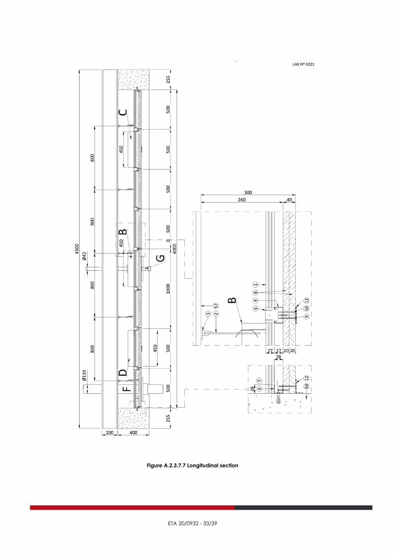
A.2.3.4 Assessed installation
All installation details of the assessed installation are presented in paragraph A.2.3.7.
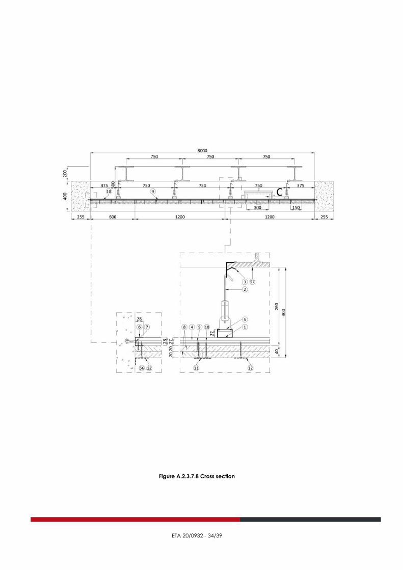
The dimensions of the assessed installation are 4000 mm by 3000 mm, with a ceiling thickness of 40 mm. The installations main
components are :
− A concealed metal grid comprising:
• main runners, nominal length 4000 mm, made from Profilo S4927 C-shaped galvanised sheet steel channel, nominal
size 49 mm x 27 mm and nominal thickness 0,6 mm, positioned parallel to the steel beams at a nominal centre-to-
centre distance of 750 mm, suspended by hangers placed at a nominal centre-to-centre distance of 800 mm and
secured to the bottom flanges of the supporting construction beams using steel clips;
• the hangers comprise a lower connector called “Spring-type hanger for S4927 channels”, inserted in the channel,
and an upper steel bar, nominal diameter 4 mm, inserted at the bottom into the holes of the lower connector
spring and fastened at the top to the steel clip;
• Profilo S4927 C-shaped galvanised-sheet-steel cross tees, nominal length 3000 mm, nominal size 49 mm x 27 mm
and nominal thickness 0,6 mm, placed at a nominal centre-to-centre distance of 500 mm perpendicular to the
main runners to which they are fastened using sheet-steel connectors, nominal thickness 0,7 mm, called
“Connecting hanger for S4927 channels”;
• U-shaped galvanised-sheet-steel perimeter trim, nominal size 28 mm x 28 mm and nominal thickness 0,6 mm,
secured to the test frame using steel expansion anchors, nominal diameter 9 mm and nominal length 45 mm,
placed at a nominal centre-to-centre distance of 500 mm;
− An infill, total thickness 40 mm, placed 300 mm from the underside of the steel beams, leaving a gap of 260 mm between
the suspended ceiling tiles and beam bottom flanges, and formed by 2 layers of PROMATECT-100X silicate and sulphate-
based board with PROMAXON engineered mineral matrix having core thickened and fibre-reinforced by functional
additives, standard nominal size 2500 mm x 1200 mm, nominal thickness 20 mm and nominal mass per unit area 17 kg/m²,
arranged with staggered joints and secured to the cross-tee and perimeter-trim channels using steel self-tapping screws,
nominal diameter 3,5 mm each and nominal length 35 mm the first layer, where they are placed at a nominal centre-
to-centre distance of 300 mm, and 55 mm for the second layer, where they are placed at a nominal centre-to-centre
distance of 150 mm;
on the underside of the infill, the joints between boards are sealed with microperforated paper tape and gypsum putty,
whilst screw heads and perimeter edges are sealed with the gypsum putty only;
7 fittings are installed in the suspended ceiling infill, as described hereafter.
− Fittings “A”, “B” and “C”
Fittings “A”, “B” and “C” consist of a luminaire or more specifically a round downlight, effective diameter 60 mm, inserted
in a special cut-out in the suspended ceiling tiles, in the centre of a section of the grid formed by the supporting metal
framework, having a length of power supply cable and protected on top by luminaire cover comprising a box-type
enclosure, nominal plan-view dimensions 450 mm x 380 mm, nominal height 130 mm and nominal thickness of walls
40 mm, formed by walls consisting of 2 layers of PROMATECT-100X silicate and sulphate-based board with PROMAXON
engineered mineral matrix having core thickened and fibre-reinforced by functional additives, nominal thickness 20 mm
and nominal mass per unit area 17 kg/m², previously joined together using a steel self-tapping screw, nominal diameter
3,5 mm and nominal length 35 mm, and assembled using steel clips, nominal width 10 mm, nominal length 50 mm and
nominal thickness 1 mm, and Promat K84 high-temperature bonding agent.

ETA 20/0932 - 25/39
The downlight power supply cable exits the luminaire cover though a hole made in the middle of the top where it is
sealed with PROMASEAL A one-component acrylic firestop mastic, nominal dry density 1800 kg/m³.
The luminaire cover is left resting on the suspended ceiling infill after inserting a layer of PROMASEAL A one-component
acrylic firestop mastic, nominal dry density 1800 kg/m³, and secured using steel self-tapping screws, nominal diameter
3,5 mm and nominal length 55 mm, on two sides directly to the cross-tee channels and on the other two sides to lengths
of Profilo S4927 C-shaped galvanised sheet-steel channel, nominal length 700 mm, nominal size 49 mm × 27 mm and
nominal thickness 0,6 mm, positioned at right-angles to the cross tees and simply resting on them.
− Fitting “D”
Fitting “D” is an inspection hatch positioned in a rectangular opening cut in the suspended ceiling infill, nominal size
604 mm × 404 mm, and comprising:
o outer frame, nominal plan-view dimensions 650 mm × 450 mm, formed by two opposite sides made from steel
angle bar, nominal size 20 mm × 20 mm and nominal thickness 0,8 mm, and two other sides made from
└┐-shaped section, nominal size 47 mm × 20 mm and nominal thickness 0,8 mm;
the latter profiled sections are secured to the cross-tee channels using steel self-tapping screws, nominal
diameter 4,2 mm and nominal length 13 mm, placed at a nominal centre-to-centre distance of 150 mm;
o door comprising:
▪ perimeter frame formed by T-shaped sides that are assembled by spot welding a steel plate, nominal
width 50 mm and nominal thickness 0,8 mm, to a steel angle bar, nominal size 30 mm × 20 mm and
nominal thickness 0,8 mm;
▪ upper protection of perimeter frame created with strip, nominal size 50 mm × 20 mm, cut from
PROMATECT-100X silicate and sulphate-based board with PROMAXON engineered mineral matrix
having core thickened and fibre-reinforced by functional additives, nominal mass per unit area
17 kg/m², secured to the perimeter frame using steel self-tapping screws, nominal diameter 3,5 mm
each and nominal length 35 mm, placed at a nominal centre-to-centre distance of 150 mm;
▪ infill, nominal thickness 40 mm, formed by 2 PROMATECT-100X silicate and sulphate-based boards with
PROMAXON engineered mineral matrix having core thickened and fibre-reinforced by functional
additives, nominal thickness 20 mm and nominal mass per unit area 17 kg/m² each and nominal size
605 mm × 405 mm for the upper one and 600 mm × 400 mm for the lower one, fixed on the underside
to the perimeter frame using steel self-tapping screws, nominal diameter 3,5 mm and nominal length
55 mm, placed at a nominal centre-to-centre distance of 150 mm;
the perimeter edge of the lower board is fitted with a PROMASEAL-PL graphite intumescent seal,
nominal size 20 mm × 1,8 mm and nominal mass per unit area 1,8 kg/m², secured by metal clips,
nominal width 10 mm, nominal length 20 mm and nominal thickness 1 mm.
− Fitting “E”
Fitting “E” is an inspection hatch positioned in a square opening cut in the suspended ceiling infill, nominal size 404 mm
x 404 mm, and comprising:
o outer frame, nominal plan-view dimensions 450 mm × 450 mm, formed by two opposite sides made from steel
angle bar, nominal size 20 mm × 20 mm and nominal thickness 0,8 mm, and two other sides made from -shaped
section, nominal size 47 mm × 20 mm and nominal thickness 0,8 mm;
the latter profiled sections are secured to the cross-tee channels using steel self-tapping screws, nominal
diameter 4,2 mm and nominal length 13 mm, placed at a nominal centre-to-centre distance of 150 mm;
o door comprising:
▪ perimeter frame formed by T-shaped sides that are assembled by spot welding a steel plate, nominal
width 50 mm and nominal thickness 0,8 mm, to a steel angle bar, nominal size 30 mm × 20 mm and
nominal thickness 0,8 mm;
▪ upper protection of perimeter frame created with strip, nominal size 50 mm × 20 mm, cut from
PROMATECT-100X silicate and sulphate-based board with PROMAXON engineered mineral matrix
having core thickened and fibre-reinforced by functional additives, nominal mass per unit area
17 kg/m², secured to the perimeter frame using steel self-tapping screws, nominal diameter 3,5 mm
each and nominal length 35 mm, placed at a nominal centre-to-centre distance of 150 mm;
▪ infill, nominal thickness 42 mm, formed by 2 PROMATECT-100X silicate and sulphate-based boards with
PROMAXON engineered mineral matrix having core thickened and fibre-reinforced by functional
additives, nominal thickness 20 mm and nominal mass per unit area 17 kg/m² each and nominal size
405 mm × 405 mm for the upper one and 400 mm × 400 mm for the lower one, fixed on the underside
to the perimeter frame using steel self-tapping screws, nominal diameter 3,5 mm and nominal length
55 mm, placed at a nominal centre-to-centre distance of 150 mm;
the perimeter edge of the lower board is fitted with a PROMASEAL-PL graphite intumescent seal,
nominal size 20 mm × 1,8 mm and nominal mass per unit area 1,8 kg/m², secured by metal clips,
nominal width 10 mm, nominal length 20 mm and nominal thickness 1 mm.

ETA 20/0932 - 26/39
− Fitting “F”
Fitting “F” is a polypropylene homopolymer (PPH) pipe, nominal length 1000 mm, nominal outside diameter 110 mm and
nominal wall thickness 2,8 mm, placed inside a hole, nominal diameter 120 mm, made in both the suspended ceiling
infill and an additional PROMATECT-100X silicate and sulphate-based board with PROMAXON engineered mineral matrix
having core thickened and fibre-reinforced by functional additives, nominal size 300 mm × 300 mm, nominal thickness
20 mm and nominal mass per unit area 17 kg/m², placed on the underside of the infill, and protected on the fire-exposed
face by a PROMASTOP FC6/110 firestop collar, nominal inside diameter 120 mm, nominal outside diameter 142 mm and
nominal depth 60 mm, comprising a flexible powder-coated stainless-steel band, wrapped around the pipe, with a
graphite-based intumescent inlay, nominal density 1000 kg/m³, and having 4 fasteners for on-site installation; both the
additional board and firestop collar are secured by 4 galvanised-steel anchors, nominal diameter 4 mm, inserted in
holes, nominal diameter 14 mm, drilled in both the suspended ceiling infill and additional board and sealed with
PROMASEAL A one-component acrylic firestop mastic, nominal dry density 1800 kg/m³.
The remaining gap in the hole between suspended ceiling infill and pipe was sealed on the underside of the suspended
ceiling using said PROMASEAL A one-component acrylic firestop mastic, nominal dry density 1800 kg/m³.
− Fitting “G”
Fitting “G” is a steel pipe, nominal length 800 mm, nominal outside diameter 42 mm and nominal wall thickness 5 mm,
sealed off at the base by a steel plug and placed inside a hole, maximum nominal diameter 60 mm at the suspended
ceiling infill and minimum nominal diameter 42 mm at an additional PROMATECT-100X silicate and sulphate-based board
with PROMAXON engineered mineral matrix having core thickened and fibre-reinforced by functional additives, nominal
size 300 mm x 300 mm, nominal thickness 20 mm and nominal mass per unit area 17 kg/m², placed on the top side of the
infill and secured to it using 4 galvanised-steel anchors, nominal diameter 4 mm, inserted in holes, nominal diameter
14 mm, drilled in both the suspended ceiling infill and additional board and sealed with PROMASEAL A one-component
acrylic firestop mastic, nominal dry density 1800 kg/m³.
The pipe is protected on the unexposed face by 2 stone-wool insulation wraps, nominal outside diameter 102 mm,
nominal inside diameter 42 mm, nominal height 70 mm and nominal density 100 kg/m³ each, and covered at the hole
in the suspended ceiling infill by a loop of PROMASTOP-W graphite intumescent firestop tape, nominal size 40 mm x
2,5 mm.
A.2.3.5 Direct field of application
The results of the fire resistance classification are directly applicable to constructions of the assessed construction, where only one
or more of the modifications listed below are made.
− Constructions with fire exposure from below
− The classification may be applied to ceilings of any dimension, provided that the distribution per unit area of
the hangers is not reduced, and the distance between hangers is not increased. The distance between grid
members and the load on the hanger shall not be increased. Provisions for expansion in the ceiling system shall
be increased pro rata with the extension in sizes, while the gap at the perimeter shall be the same as tested.
− Fittings which may be installed are those which have been included in the assessed installation. The distance
between the fittings cannot be smaller than tested.
− The classifications are valid for cavities of any height.
− The classifications are applicable to ceilings suspended by hangers of any length.
− The classifications are only applicable to the inclusion of cables, pipes etc above the ceiling provided they are
installed in such a manner that they give no additional mechanical load to the ceilings during the fire.
A.2.3.6 Details
All installation details shall be executed as presented in paragraph A.2.3.7.

ETA 20/0932 - 27/39
A.2.3.7 Figures
Figure A.2.3.7.1 Key (part 1)

ETA 20/0932 - 28/39
Figure A.2.3.7.2 Key (Part 2)

ETA 20/0932 - 29/39
Figure A.2.3.7.3 Key (Part 3)

ETA 20/0932 - 30/39
Figure A.2.3.7.4 Key (Part 4)

ETA 20/0932 - 31/39
Figure A.2.3.7.5 : Underside pf assessed installation

ETA 20/0932 - 32/39
Figure A.2.3.7.6 Suspended ceiling top side
ETA 20/0932 - 33/39
Figure A.2.3.7.7 Longitudinal section
ETA 20/0932 - 34/39
Figure A.2.3.7.8 Cross section

ETA 20/0932 - 35/39
Figure A.2.3.7.9 Schematic drawing of fittings “A”, “B” and “C”

ETA 20/0932 - 36/39
Figure A.2.3.7.10 Schematic drawing of fitting “D”

ETA 20/0932 - 37/39
Figure A.2.3.7.11 Schematic drawing of fitting “E”

ETA 20/0932 - 38/39
Figure A.2.3.7.12 Schematic drawing of fitting “F”

ETA 20/0932 - 39/39
Figure A.2.3.7.13 Schematic drawing of fitting “G”