essential testing of wlan equipment service provider ... plan essential testing of wlan equipment...
TRANSCRIPT

TEST PLAN
Essential Testing of WLAN Equipment
Service Provider WLAN Master Test Plan
915-6055-01 Version 1.0, February 2008www.ixiacom.com

VeriWave, Inc. Essential Testing of WLAN Equipment
PROPRIETARY AND CONFIDENTIAL TO VERIWAVE, INC. PAGE 2 OF 298
Essential Testing of WLAN Equipment
Version History Date Version Comments
02/01/2008 1.0 First Revision

VeriWave, Inc. Essential Testing of WLAN Equipment
PROPRIETARY AND CONFIDENTIAL TO VERIWAVE, INC. PAGE 3 OF 298
Essential Testing of WLAN Equipment
Table of Contents Version History .................................................................................................. 2 Table of Contents .............................................................................................. 3 Introduction ....................................................................................................... 8 Goals .................................................................................................................. 9 SUT Overview .................................................................................................. 10 VeriWave Applications .................................................................................... 12
Data Plane ............................................................................................................... 12 Unicast Throughput .............................................................................. 12 Unicast Forwarding Rate ....................................................................... 13 Unicast Packet Loss ............................................................................... 13 Unicast Latency ..................................................................................... 14 Multicast Forwarding Rate .................................................................... 14 TCP Goodput ........................................................................................ 14
Control Plane ........................................................................................................... 15 Benchmark Roaming ............................................................................. 15 Multicast Roaming ................................................................................ 15 Stress Association Database Capacity (Client Capacity) ..................... 15 AP Load Balancing ................................................................................ 16 Frame Generator .................................................................................. 16 Connection Stress Test ......................................................................... 17 Concurrent Connections Test .............................................................. 17 Thin AP Failover Test ............................................................................ 17
QoS .......................................................................................................................... 17 VoIP QoS Service Capacity ................................................................... 18 VoIP Service Assurance ......................................................................... 18 QoS Service Differentiation .................................................................. 18 VoIP Roaming ........................................................................................ 19
Mesh ........................................................................................................................ 19 Mesh client capacity ............................................................................. 19 Mesh VoIP call capacity ........................................................................ 20 Mesh Throughput per hop ................................................................... 20 Mesh Forwarding Rate per hop ............................................................ 20 Mesh Latency per hop .......................................................................... 20 Mesh Backhaul Failover (Self-healing) ................................................. 20
Miscellaneous .......................................................................................................... 21 AAA Authentication Load ..................................................................... 21 Power-Save Throughput ....................................................................... 21 RFID Traffic Generator .......................................................................... 21 Record and Replay Test ........................................................................ 21
Test-bed Configuration ................................................................................... 22 Test Case Profiles ............................................................................................ 24
Mesh Test Profile .................................................................................................... 24 QoS Test Profile ...................................................................................................... 27
VeriWave, Inc. Essential Testing of WLAN Equipment
PROPRIETARY AND CONFIDENTIAL TO VERIWAVE, INC. PAGE 4 OF 298
Essential Testing of WLAN Equipment
Roaming Test Profile .............................................................................................. 28 Test Plan .......................................................................................................... 29
Functional Verification ............................................................................................ 29 Association ............................................................................................ 29 ATC-SP 001 Mixed_80211bg-mode_Association ......................................... 29 ATC-SP 002 Basic_80211a-mode_Association ............................................. 31 Security and DHCP ............................................................................... 33 STC-SP 001 Security_Baseline_Test .............................................................. 34 STC-SP 002 Open_WEP40 .............................................................................. 36 STC-SP 003 Open_WEP128 ............................................................................ 38 STC-SP 004 Shared-Key_WEP40 .................................................................... 40 STC-SP 005 Shared-Key_WEP128 .................................................................. 42 STC-SP 006 WPA_PSK_And_WPA_PSK_AES ............................................... 44 STC-SP 007 WPA2_PSK_And_WPA2_PSK_TKIP ........................................... 46 STC-SP 008 Mixed_WPA_WPA2_PSK ........................................................... 48 Basic Forwarding .................................................................................. 50 BTC-SP 001 Upstream_80211g_Packet_Loss_Sweep .................................. 50 BTC-SP 002 Downstream_80211g_Packet_Loss_Sweep ............................. 52 BTC-SP 003 Bidirectional_80211g_Packet_Loss_Sweep ............................. 54 BTC-SP 004 Upstream_80211a_Packet_Loss_Sweep ................................... 57 BTC-SP 005 Downstream_80211a_Packet_Loss_Sweep .............................. 59 BTC-SP 006 Bidirectional_80211a_Packet_Loss_Sweep .............................. 61 Power Save ............................................................................................ 63 PTC-SP 001 Power_Save_Baseline_CAM_Test ............................................. 63 PTC-SP 002 Power-Save_Legacy_PS_Poll ..................................................... 65 PTC-SP 003 Power-Save_Legacy_Null_Frame .............................................. 67 PTC-SP 004 Power-Save_APSD ...................................................................... 69 PTC-SP 005 Power-Save_Mixed_3 ................................................................. 71 PTC-SP 006 Power-Save_Mixed_5 ................................................................. 74 PTC-SP 007 Power-Save_Transition_2 ........................................................... 76 QoS ....................................................................................................... 79 QTC-SP 001 Basic_WMM_Association .......................................................... 80 QTC-SP 002 Single_Station_Downstream_Fairness .................................... 82 QTC-SP 003 Single_Station_Downstream_Priority ...................................... 84 QTC-SP 004 Multi_Station_Downstream_Fairness ...................................... 87 QTC-SP 005 Multi_Station_Downstream_Priority ........................................ 90 QTC-SP 006 Multi_Station_Upstream_Fairness ........................................... 93 QTC-SP 007 Multi_Station_Upstream_Priority ............................................. 95 QTC-SP 008 Legacy_QoS_Coexistence ........................................................ 98 QTC-SP 009 Basic_Call_Admission_Control............................................... 102 QTC-SP 010 Call_Admission_Control_Denial_PHY_Rate .......................... 104 QTC-SP 011 Call_Admission_Control_Denial_Utilization ......................... 107 QTC-SP 012 Call_Admission_Control_Codec_Type .................................. 109 QTC-SP 013 Call_Admission_Control_Mesh .............................................. 111 Denial of Service Attack Resilience .................................................... 113
VeriWave, Inc. Essential Testing of WLAN Equipment
PROPRIETARY AND CONFIDENTIAL TO VERIWAVE, INC. PAGE 5 OF 298
Essential Testing of WLAN Equipment
DTC-SP 001 Authentication_Flood_Protection .......................................... 113 DTC-SP 002 Deauthentication_Flood_Protection ...................................... 115 DTC-SP 003 Association_Flood_Protection ................................................ 116 DTC-SP 004 Broadcast-Probe_Flood_Protection ....................................... 117 DTC-SP 005 Disassociation_Flood_Protection ........................................... 118 DTC-SP 006 Reassociation-Request_Flood_Protection ............................. 120 DTC-SP 007 Invalid_SSID_Association_Protection .................................... 121 DTC-SP 008 Invalid_Beacon_Protection ..................................................... 122 DTC-SP 009 Invalid_Power-Save-Poll_Protection ....................................... 123 DTC-SP 010 Bad_Data-Frame_Protection .................................................. 125
Performance and Capacity Benchmarks ............................................................. 126 Capacity and Coverage Benchmarking .............................................. 126 Client/Call Capacity ............................................................................ 126 CBTC-SP 001 Max_Client_Capacity_DHCP ................................................ 127 CBTC-SP 002 Max_VoIP_Call_Capacity_DHCP .......................................... 129 CBTC-SP 003 Max_Mesh_Client_Capacity_DHCP ..................................... 131 CBTC-SP 004 Max_Mesh_VoIP_Call_Capacity_DHCP .............................. 132 Rate vs. Range..................................................................................... 133 CBTC-SP 010 Rate_vs_Range_80211b ........................................................ 134 CBTC-SP 011 Rate_vs_Range_80211g ........................................................ 135 CBTC-SP 012 Rate_vs_Range_80211a ......................................................... 136 Performance Benchmarking ............................................................... 138 Throughput ......................................................................................... 138 PBTC-SP 001 Upstream_UDP_80211g_Throughput .................................. 138 PBTC-SP 002 Downstream_UDP_80211g_Throughput ............................. 140 PBTC-SP 003 Bidirectional_UDP_80211g_Throughput ............................. 141 PBTC-SP 004 Upstream_UDP_80211a_Throughput ................................... 143 PBTC-SP 005 Downstream_UDP_80211a_Throughput .............................. 145 PBTC-SP 006 Bidirectional_UDP_80211a_Throughput .............................. 146 PBTC-SP 007 Upstream_TCP_80211g_Throughput ................................... 148 PBTC-SP 008 Downstream_TCP_80211g_Throughput .............................. 149 PBTC-SP 009 Upstream_TCP_80211a_Throughput ................................... 151 PBTC-SP 010 Downstream_TCP_80211a_Throughput .............................. 153 PBTC-SP 011 Downstream_UDP_Power_Save_80211g_Throughput ....... 154 PBTC-SP 012 Downstream_UDP_Power_Save_80211a_Throughput ....... 156 PBTC-SP 013 Downstream_TCP_Power_Save_80211g_Throughput ....... 158 PBTC-SP 014 Downstream_TCP_Power_Save_80211a_Throughput ........ 160 Packet Latency .................................................................................... 162 PBTC-SP 020 Upstream_80211g_Packet_Latency ...................................... 162 PBTC-SP 021 Downstream_80211g_Packet_Latency ................................. 164 PBTC-SP 022 Upstream_80211a_Packet_Latency ...................................... 166 PBTC-SP 023 Downstream_80211a_Packet_Latency ................................. 167 Packet Loss .......................................................................................... 169 PBTC-SP 030 Upstream_80211g_Packet_Loss ........................................... 169 PBTC-SP 031 Downstream_80211g_Packet_Loss ...................................... 171

VeriWave, Inc. Essential Testing of WLAN Equipment
PROPRIETARY AND CONFIDENTIAL TO VERIWAVE, INC. PAGE 6 OF 298
Essential Testing of WLAN Equipment
PBTC-SP 032 Upstream_80211a_Packet_Loss ............................................ 173 PBTC-SP 033 Downstream_80211a_Packet_Loss ....................................... 175 Maximum Forwarding Rate ................................................................ 177 PBTC-SP 040 Upstream_80211g_Max_Forwarding Rate ........................... 177 PBTC-SP 041 Downstream_80211g_Max_Forwarding Rate ...................... 179 PBTC-SP 042 Upstream_80211a_Max_Forwarding Rate ........................... 180 PBTC-SP 043 Downstream_80211a_Max_Forwarding Rate ...................... 182 Maximum Stateful TCP Goodput ....................................................... 183 PBTC-SP 050 Upstream_80211g_Max_TCP_Goodput .............................. 184 PBTC-SP 051 Downstream_80211g_Max_TCP_Goodput ......................... 186 PBTC-SP 052 Upstream_80211a_Max_TCP_Goodput ............................... 187 PBTC-SP 053 Downstream_80211a_Max_TCP_Goodput .......................... 189 Roaming Performance ........................................................................ 191 PBTC-SP 070 Roaming_Delay_80211g_Baseline ........................................ 191 PBTC-SP 071 Roaming_Delay_80211a_Baseline ........................................ 193 PBTC-SP 072 Roaming_Delay_80211g_Secure .......................................... 194 PBTC-SP 073 Roaming_Delay_80211a_Secure ........................................... 196 PBTC-SP 074 Roaming_Delay_80211g_DHCP ........................................... 198 PBTC-SP 075 Roaming_Delay_80211a_DHCP ............................................ 199 PBTC-SP 076 Roaming_Delay_80211g_MultiSSID ..................................... 201 PBTC-SP 077 Roaming_Delay_80211a_MultiSSID ..................................... 203 Mesh Per-Hop and Aggregate Throughput ....................................... 206 PBTC-SP 100 Upstream_UDP_Per-Hop_Throughput ................................ 206 PBTC-SP 101 Downstream_UDP_Per-Hop_Throughput ........................... 208 PBTC-SP 102 Bidirectional_UDP_Per-Hop_Throughput ........................... 210 PBTC-SP 103 Upstream_TCP_Per-Hop_Throughput ................................. 211 PBTC-SP 104 Downstream_TCP_Per-Hop_Throughput ............................ 213 PBTC-SP 105 Bidirectional_TCP_Per-Hop_Throughput ............................ 215 PBTC-SP 106 Upstream_UDP_Aggregate_Throughput ............................ 217 PBTC-SP 107 Downstream_UDP_Aggregate_Throughput ....................... 218 PBTC-SP 108 Bidirectional_UDP_Aggregate_Throughput ....................... 220 PBTC-SP 109 Upstream_TCP_Aggregate_Throughput ............................. 222 PBTC-SP 110 Downstream_TCP_Aggregate_Throughput ........................ 224 PBTC-SP 111 Bidirectional_TCP_Aggregate_Throughput ........................ 226 Mesh Per-Hop and Aggregate Packet Latency .................................. 228 PBTC-SP 140 Upstream_UDP_Per-Hop_Latency ....................................... 228 PBTC-SP 141 Downstream_UDP_Per-Hop_Latency .................................. 230 PBTC-SP 142 Upstream_UDP_Aggregate_Latency ................................... 232 PBTC-SP 143 Downstream_UDP_Aggregate_Latency .............................. 233 Quality Of Service ............................................................................... 235 PBTC-SP 160 Basic_QoS_Service_Differentiation_2Levels ....................... 236 PBTC-SP 161 Basic_QoS_Service_Differentiation_4Levels ....................... 238 PBTC-SP 162 VoIP_SLA_Assurance ............................................................. 240 PBTC-SP 163 VoIP_Roaming_80211g .......................................................... 243 PBTC-SP 164 VoIP_Roaming_80211a .......................................................... 244

VeriWave, Inc. Essential Testing of WLAN Equipment
PROPRIETARY AND CONFIDENTIAL TO VERIWAVE, INC. PAGE 7 OF 298
Essential Testing of WLAN Equipment
Multicast .............................................................................................. 246 PBTC-SP 180 Multicast_Forwarding_Rate .................................................. 247 PBTC-SP 181 Multicast_Latency_And_Jitter ............................................... 249 Client Association Rate ....................................................................... 251 PBTC-SP 200 Max_Client_Association_Rate_DHCP .................................. 251
System and Stress Testing ................................................................................... 253 System Resiliency and Availability ...................................................... 253 OFTC-SP 001 Mesh_Recovery ..................................................................... 254 OFTC-SP 002 AP_Reset_Recovery ............................................................... 256 Traffic Variation ................................................................................... 258 TVTC-SP 001 Data_Load_Isolation .............................................................. 258 TVTC-SP 002 Roaming_Isolation_Network ................................................. 261 WiMix Tests ......................................................................................... 263 WMTC-SP 001 WiMix_Triple_Play_Unicast ................................................. 264 WMTC-SP 002 WiMix_Triple_Play_Multicast .............................................. 266 Mesh Interference Effects ................................................................... 269 IETC-SP 001 Mesh_Interference_Reroute ................................................... 269 IETC-SP 002 Mesh_UDP_Throughput_Interference_Impact ..................... 271 IETC-SP 003 Mesh_Latency_Interference_Impact ...................................... 273
Accelerated Stress Testing .................................................................................. 276 Traffic Stress ........................................................................................ 277 TSTC-SP 001 Traffic_Stress ........................................................................... 277 Roaming Stress ................................................................................... 280 RSTC-SP 001 VoIP_Roaming_Stress ............................................................ 280 Connection Stress ............................................................................... 283 CSTC-SP 001 Client_Connection_Stress ..................................................... 283 CSTC-SP 002 Client_Connection_Data_Overload_Stress ......................... 287 Overload Recovery ............................................................................. 291 ORTC-SP 001 Data_Overload_Recovery ..................................................... 291 ORTC-SP 002 Connection_Overload_Recovery ......................................... 295

VeriWave, Inc. Essential Testing of WLAN Equipment
PROPRIETARY AND CONFIDENTIAL TO VERIWAVE, INC. PAGE 8 OF 298
Essential Testing of WLAN Equipment
Introduction WLAN (Wi-Fi™) networks are rapidly expanding into many service provider deployments and usage models. It is becoming a key access technology in the Multi-Dwelling Unit (MDU) space, campus and enterprise meshes, hot-spots, and municipal wireless mesh networks for city operations, emergency services, and public access. Since the deployment of such Wi-Fi networks is becoming critical to many service provider revenue models, it is imperative that these networks be tested for compliance, performance, reliability and security to ensure a high-quality end-user experience.
When the dominant use of WLAN was for in-home convenience, it was sufficient to perform only basic connectivity and interoperation tests using simple traffic simulation devices based on off-the-shelf laptops and handhelds. With the transition into the enterprise and service provider spaces, the expectation of the end customer is for the same level of quality that the wired LAN industry has delivered. Because wireless networks provide access for a wide variety of clients with many levels of performance requirements, wireless network equipment must be qualified with regards to all traffic behaviors, power management techniques, security methods and in the presence of all types of clients simultaneously. This test plan provides the carrier-class test coverage necessary to ensure compliance and performance of WLAN systems.
Essential WLAN testing requirements for service provider requirements can be categorized into four major areas - functional verification, performance measurement and network capacity assessment, system testing, and stress testing.

VeriWave, Inc. Essential Testing of WLAN Equipment
PROPRIETARY AND CONFIDENTIAL TO VERIWAVE, INC. PAGE 9 OF 298
Essential Testing of WLAN Equipment
Goals This test plan addresses the testing requirements of WLAN service provider infrastructure equipment by focusing on the four major categories mentioned above. The test plan uses the VeriWave WaveTest™ Traffic Generator and Analyzer (TGA) platform to test WLAN equipment such as APs, WLAN controllers, and LAN switches (hereby collectively called the SUT). These tests should be conducted during hardware and software qualification, software/firmware release testing, vendor selection, or pre-deployment testing.
The focus of this test plan is on security policies, voice and video support, power management, bandwidth capacity, and performance of the WLAN infrastructure (APs, WLAN controllers, and wired infrastructure elements – Ethernet switches, servers etc.).

VeriWave, Inc. Essential Testing of WLAN Equipment
PROPRIETARY AND CONFIDENTIAL TO VERIWAVE, INC. PAGE 10 OF 298
Essential Testing of WLAN Equipment
SUT Overview The important building blocks that constitute the SUT and some key functionality that may be supported include the following:
• WLAN Access Point Establishes the wireless channel(s) for communication with WLAN
clients Authenticates and allows clients to connect to the WLAN Acts as a conduit for WLAN client traffic sent to and received from the
wired network and also between clients in the same BSS Encrypts and decrypts 802.11 frames destined to and originating from
WLAN clients, if security is turned on
• WLAN Controller Supports various client management functions such as allowing client
associations, authentications and maintaining or rejecting connections Performs security handshakes required by security protocols as well as
port-based authentication Manages prioritization of traffic flowing into and out of the SUT as well
as bandwidth management Balances client load to limit the number of client connections accepted
to ensure that the traffic handling performance is not disrupted Acts as a stateful firewall that controls access and inspects traffic flow
in order to enforce user/group policies and prevent denial-of-service attacks
Implements IDS/IPS modules to detect and prevent intrusions from disrupting the availability of the WLAN
Executes, controls and manages mobility aspects including Layer 3 roaming and fast roaming
Provides SSID/BSSID and VLAN management to support all the virtual networks supported by the WLAN and wired-LAN
Switches traffic from/to multiple downstream ports on the controller to the up-link port(s) as well as switching traffic between different downstream ports
VeriWave, Inc. Essential Testing of WLAN Equipment
PROPRIETARY AND CONFIDENTIAL TO VERIWAVE, INC. PAGE 11 OF 298
Essential Testing of WLAN Equipment
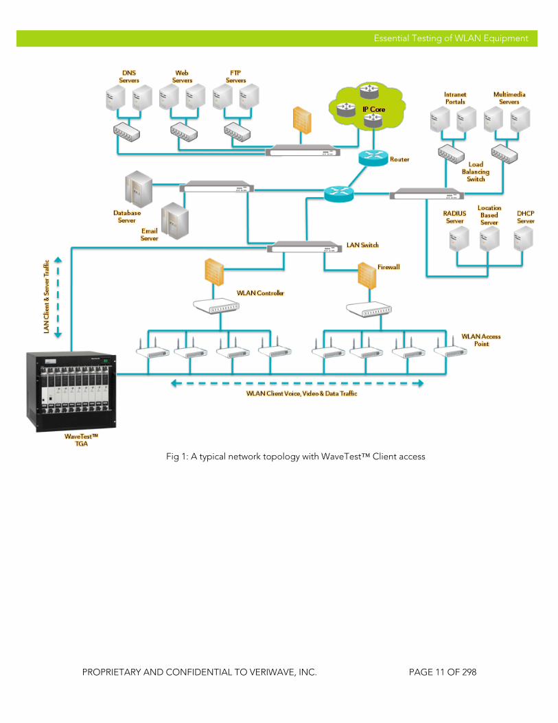
Fig 1: A typical network topology with WaveTest™ Client access

VeriWave, Inc. Essential Testing of WLAN Equipment
PROPRIETARY AND CONFIDENTIAL TO VERIWAVE, INC. PAGE 12 OF 298
Essential Testing of WLAN Equipment
VeriWave Applications A variety of test applications are available for the WaveTest platform. New applications are being added continuously, and the VeriWave website contains a current listing, as well as an updated version of this document. All of these applications provide a Command-Line-Interface (CLI) that can be integrated into an automation framework which will configure and manage both the SUT and the WaveTest system for fully automated execution and reporting.
Shown below is a list of applications available at the time this document was released. Some of the applications listed also have GUI interfaces available for driving the scripts, which allows for more manual operation and functional testing as desired. The results from these tests can be compared to other versions of the same SUT (as in previous SW and FW versions), as well as to competing products from other vendors.
The applications are arbitrarily classified for easier comprehension into five categories: Data Plane, Control Plane / Security, QoS, Mesh and Miscellaneous.
Data Plane The following tests measure performance metrics and also expose issues relating to bandwidth, delay times and data integrity thereby allowing the tester to quantify, qualify and benchmark the data plane of the SUT.
Unicast Throughput
The Throughput test identifies the maximum rate at which the system under test (SUT) can forward packets without loss.
This test determines the throughput rate by using a binary search algorithm. The test starts by offering the maximum theoretical or user-specified load to the SUT. Packet loss is then measured. If packet loss is detected the offered load (OLOAD) is cut in half. If there is no packet loss the OLOAD is doubled. This process continues until the difference between OLOAD values is less than the search resolution setting. The process is repeated for each frame size specified in the test.
The results show the throughput rates in frames per second for each frame size and the average throughput rate for all trials.
Running this test provides a baseline of the SUT’s overall capability to handle traffic. It is a standard measure of performance as defined by draft-IEEE-802.11.2 (similar to RFC 2544 for wired networks). The throughput number can be easily compared to theoretical limits, at any given frame size, to other versions of the same SUT (as in previous SW and FW versions), as well as to competing products from other vendors. The throughput number provides the absolute maximum capacity of the SUT to pass traffic with no loss, and sets the bar for the most stringent applications. Successfully passing this test verifies
VeriWave, Inc. Essential Testing of WLAN Equipment
PROPRIETARY AND CONFIDENTIAL TO VERIWAVE, INC. PAGE 13 OF 298
Essential Testing of WLAN Equipment
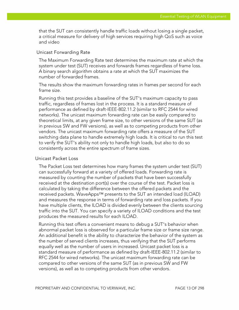
that the SUT can consistently handle traffic loads without losing a single packet, a critical measure for delivery of high services requiring high QoS such as voice and video
Unicast Forwarding Rate
The Maximum Forwarding Rate test determines the maximum rate at which the system under test (SUT) receives and forwards frames regardless of frame loss. A binary search algorithm obtains a rate at which the SUT maximizes the number of forwarded frames.
The results show the maximum forwarding rates in frames per second for each frame size.
Running this test provides a baseline of the SUT’s maximum capacity to pass traffic, regardless of frames lost in the process. It is a standard measure of performance as defined by draft-IEEE-802.11.2 (similar to RFC 2544 for wired networks). The unicast maximum forwarding rate can be easily compared to theoretical limits, at any given frame size, to other versions of the same SUT (as in previous SW and FW versions), as well as to competing products from other vendors. The unicast maximum forwarding rate offers a measure of the SUT switching data plane to handle extremely high loads. It is critical to run this test to verify the SUT’s ability not only to handle high loads, but also to do so consistently across the entire spectrum of frame sizes.
Unicast Packet Loss
The Packet Loss test determines how many frames the system under test (SUT) can successfully forward at a variety of offered loads. Forwarding rate is measured by counting the number of packets that have been successfully received at the destination port(s) over the course of the test. Packet loss is calculated by taking the difference between the offered packets and the received packets. WaveApps™ presents to the SUT an intended load (ILOAD) and measures the response in terms of forwarding rate and loss packets. If you have multiple clients, the ILOAD is divided evenly between the clients sourcing traffic into the SUT. You can specify a variety of ILOAD conditions and the test produces the measured results for each ILOAD.
Running this test offers a convenient means to debug a SUT’s behavior when abnormal packet loss is observed for a particular frame size or frame size range. An additional benefit is the ability to characterize the behavior of the system as the number of served clients increases, thus verifying that the SUT performs equally well as the number of users in increased. Unicast packet loss is a standard measure of performance as defined by draft-IEEE-802.11.2 (similar to RFC 2544 for wired networks). The unicast maximum forwarding rate can be compared to other versions of the same SUT (as in previous SW and FW versions), as well as to competing products from other vendors.

VeriWave, Inc. Essential Testing of WLAN Equipment
PROPRIETARY AND CONFIDENTIAL TO VERIWAVE, INC. PAGE 14 OF 298
Essential Testing of WLAN Equipment
Unicast Latency
The Unicast latency test determines the latency of the system under test (SUT). The results show the latencies for each frame size as distributed into 16 latency buckets. It also shows the minimum, maximum, and average latencies for all the trials. The test presents the SUT with an intended load (ILOAD) and measures the time that it takes for frames to be forwarded through the SUT. The test compares the transmit timestamp for each frame with the receive timestamp for the corresponding frame. Frames are transmitted for a fixed period of time. The difference between the transmit time and the receive time is the latency. If you have multiple clients, the ILOAD is divided evenly between the clients sourcing traffic into the SUT. For accurate latency measurement, the ILOAD must be at a level that produces no frame loss. Use the Throughput test to determine the maximum ILOAD that can be achieved without frame loss.
Running this test provides a baseline of delay introduced by the SUT. This is a critical performance measure for any application, as high latency will cause unacceptable end-user experience especially in delay sensitive applications such as voice and video. An additional benefit is the ability to characterize the behavior of the system as the number of served clients increases, thus verifying that the SUT performs equally well as the number of users in increased. It is a standard measure of performance as defined by draft-IEEE-802.11.2 (similar to RFC 2544 for wired networks). The unicast latency be compared to other versions of the same SUT (as in previous SW and FW versions), as well as to competing products from other vendors.
Multicast Forwarding Rate
The Multicast Forwarding Rate test measures multicast forwarding rate and frame loss for a SUT with multiple ports. The test creates the required number of clients on the wireless side of the networks, and pairs them with the required servers on the Ethernet side of the network. The clients learning frames to the Ethernet side, and receive learning frames from the Ethernet side. Each multicast server generates the required traffic load to the specified multicast MAC/IP address of the client(s).
Multicast forwarding rate is defined as the number of packets/second (or the number of megabytes per second at the receiving interface) that are successfully forwarded to at least half the receiving ports at a given value of offered load.
Running this test provides verifies the SUT’s ability to properly handle multicast traffic in conjunction with proper 802.11 MAC behavior.
TCP Goodput
The TCP Goodput test measures the number of TCP payload bytes per second that the system under test (SUT) can transfer between its ports and a variable maximum segment size (MSS). The TCP payload is the sum of the TCP segment

VeriWave, Inc. Essential Testing of WLAN Equipment
PROPRIETARY AND CONFIDENTIAL TO VERIWAVE, INC. PAGE 15 OF 298
Essential Testing of WLAN Equipment
bytes minus the TCP headers and options. The test associates clients with the SUT and generates unidirectional TCP traffic. The test iterates through each element in the TCP maximum segment size list.
Running this test provides a necessary measure to verify the SUT’s ability to properly handle stateful layer 4 traffic in conjunction with proper 802.11 MAC behavior. The TCP goodput can be compared to other versions of the same SUT (as in previous SW and FW versions), as well as to competing products from other vendors, for any given maximum segment size.
Control Plane The following tests measure performance metrics and expose issues relating to roaming, client capacity, client-connection stress and intrusion detection/protection thereby allowing the tester to quantify, qualify and benchmark the control plane of the SUT.
Benchmark Roaming
The Roaming Benchmark tests the WLAN controller to determine the number of roams per unit of time the controller can support. The test determines the roam delay and packet loss at a particular roam rate with a given configuration using a predefined roaming pattern.
The test sends UDP packets from the Ethernet client to the roaming wireless clients. The roam rate and pattern are constant. After each roam operation, the test measures the time taken to roam and the number of data packets (from Ethernet to Wireless) lost during the roam. The test creates a report with the minimum, maximum and average roam delays for each test client, the number of roams performed, and the average number of packets lost per roam for each client.
Running this test provides a clear benchmark of the SUT’s ability to handle a very large scale of roaming clients, each behaving independently of the other clients. The results offered by this test are invaluable in characterizing the SUT’s behavior in a highly mobile environment, and thus a critical measure of its readiness for deployment in such an environment
Multicast Roaming The Multicast Roaming test measures roaming delays and roaming failures with multicast traffic loads.
Stress Association Database Capacity (Client Capacity)
The Maximum Client Capacity test measures the number of clients that are successfully created and pass traffic within a permissible loss tolerance. This test can exercise multiple APs. Each AP is sequentially tested. The maximum client capacity is calculated on a particular frame size and an intended load.

VeriWave, Inc. Essential Testing of WLAN Equipment
PROPRIETARY AND CONFIDENTIAL TO VERIWAVE, INC. PAGE 16 OF 298
Essential Testing of WLAN Equipment
The test first attempts to associate a large number of clients, stopping when it fails to associate any more clients or reaches the value specified for Search Maximum. Once the upper limit is determined and the learning traffic is complete, traffic runs from the Ethernet client through the SUT to the wireless clients. At the end of the transmit duration, the frame loss rate for each client is calculated. If the frame loss rate falls below the acceptable loss tolerance, the maximum number of clients has been identified and the test terminates. If the frame loss rate is above the acceptable loss tolerance, then one client is disassociated and the test runs again. This is repeated until the maximum number of clients is identified.
This test offers a very important metric of any installed network – its ability to handle multiple clients. Unlike other connection tests that may validate on the SUT’s ability to connect clients, this test actually sends traffic through these connections, thus verifying that the SUT is not only able to connect the clients, but also let traffic pass through the network.
AP Load Balancing
The AP Load Balancing test is intended to measure the load balancing capabilities of a WLAN switch/controller managing multiple access points in a given location. Any client has multiple APs as potential candidates to connect to and the WLAN controller assesses the current load on APs and forces the client using different techniques to connect to one with the least amount of load.
The application initiates one client connection at a time by scanning all channels. Clients first select the best AP to connect to depending on the number of responses, response times and RSSI then establish connection and start a traffic flow. This process is continued until the SUT cannot accept any more client connections. A successful load balancing algorithm ensures equal number of clients and traffic load on all APs.
This test is critical in planning phases of deployment of medium to large scale networks. A properly designed controller will balance load between APs ensuring good service quality to all users. This test is the only means capable to stress the SUT and validate that indeed the load balancing implanted by the controller is functioning properly.
Frame Generator
The Frame Generator test allows the user to create any kind of standard/non-standard 802.11 layer2 frame using easy to use GUI widgets and then transmit these frames at any rate. The user can control every bit of the 802.11 MAC frame starting from the Frame Control, but does not have control over the PLCP or other PHY level headers.

VeriWave, Inc. Essential Testing of WLAN Equipment
PROPRIETARY AND CONFIDENTIAL TO VERIWAVE, INC. PAGE 17 OF 298
Essential Testing of WLAN Equipment
The test also provides a list of layer 2 Denial of Service (DoS) attacks such as Deauthentication floods and Probe floods. The user can select from the list or create a list of new 802.11 frames/attacks and transmit them on any Wi-Fi port at any rate and in any order. The test allows the user to copy the hex code of any packet from any capture file and paste it into the GUI for transmission.
The test allows the user to create N number of spoofed clients with incremental MAC address and send out the frames/attacks from these N clients and also repeat the attacks/frames for N iterations.
After sending a single burst of attack frames, the test scans for the AP under test on all the channels to see if the AP is still up. If the AP doesn’t respond to probes, the test assumes the AP went down and reports a FAIL. At the end of the test a report is generated with PASS/FAIL results for all the attacks/frames transmitted.
In addition, a packet loss test can be run in the background to measure the packet loss on the SUT when such attacks are launched.
The benefit of running this test is its ability to help in debugging unique corner cases, which can not be created in a controlled and predictable manner. This can save the developer dozens of hours of trying to pinpoint a problem that occurs only in very rare cases. In addition, this test offers a unique capability to test the SUT’s ability to handle 802.11 MAC Denial of Service (DOS) attacks.
Connection Stress Test
The Connection Stress Test measures the rate at which a large number of 802.11 clients can be connected to a WLAN system (APs and controller)
Concurrent Connections Test
The Concurrent Connections Test loads a WLAN system with a large number of clients, passes traffic to/from the clients, monitors the clients and reconnects them if an AP glitches or the client traffic is interrupted. This test provides capability to create scenarios useful for placing a long-term sustained stress on the WLAN system, similar to a real-life scenario.
Thin AP Failover Test The Thin AP Failover test measures the time taken to failover from one AP to another in a situation with active and standby APs, in a controller-based system.
QoS The following tests measure performance metrics and expose issues relating to VoIP call capacity, mobile VoIP call quality and QoS-based prioritization thereby allowing the tester to quantify, qualify and benchmark the QoS performance of the SUT.

VeriWave, Inc. Essential Testing of WLAN Equipment
PROPRIETARY AND CONFIDENTIAL TO VERIWAVE, INC. PAGE 18 OF 298
Essential Testing of WLAN Equipment
VoIP QoS Service Capacity
The Service Capacity test measures the maximum number of voice calls of different types (G.711, G.729, G.723) that can be sustained by the WLAN system at a specified minimum call quality (R-value). A background best-effort data traffic load can be specified along with the voice calls. This quantifies the total voice capacity of the WLAN system.
The Ethernet port sends non-voice, data background traffic to a non-voice wireless client, creating contention for the wireless bandwidth. The test increases the number of voice calls for each iteration as long as the service level criterion is met and computes the maximum number of high priority flows the SUT can support with acceptable performance.
The service level criterion is defined as a MOS (Mean Opinion Score) or R-Value, for each of the independent voice calls created by the test system. The user has broad control over the type of voice calls created (codec type, encryption type, etc.) as well as over the 802.11e/WMM or 802.1Q user priorities assigned to the voice calls.
This test is the only tool available to characterize a SUT’s ability to handle mixed voice and data traffic while properly differentiating the various traffic types as per Layer 2 802.11e/ WMM and 802.1Q and/or Layer 3 TOS/DSCP priority settings.
VoIP Service Assurance
Measures the maximum level of best-effort data traffic load that can be presented to the WLAN system without causing the call quality of the applied voice traffic to drop below a minimum service level threshold. This quantifies the ability of the WLAN system to protect voice calls (uses WMM/802.11e, if supported by the WLAN system) from data traffic system.
The service level criterion is defined as a MOS (Mean Opinion Score) or R-Value, for each of the independent voice calls created by the test system. The user has broad control over the type of voice calls created (codec type, encryption type, etc.) as well as over the 802.11e or WMM user priorities assigned to the voice calls.
This test is the only tool available to characterize a SUT’s ability to handle mixed voice and data traffic while properly differentiating the various traffic types as per 802.11e or WMM. The test provides a clear metric of how many concurrent voice calls a SUT can carry while providing proper voice / data differentiation.
QoS Service Differentiation
Determines the various levels of service (loss, latency, jitter) provided to traffic at different priority levels, i.e., with different WMM/802.11e Access Classes and

VeriWave, Inc. Essential Testing of WLAN Equipment
PROPRIETARY AND CONFIDENTIAL TO VERIWAVE, INC. PAGE 19 OF 298
Essential Testing of WLAN Equipment
different 802.1D User Priority values. This test enables assessment of QoS implementation in WLAN systems.
VoIP Roaming
Measures call quality while roaming multiple handsets (voice calls of different types – G.711, G.729, G.723) between APs in the WLAN system. Also assesses roaming delays and lost packets. The test supports WMM/802.11e operation. The user can select the voice codec type, number of voice clients and the roaming profile. The test offers the same reports as the Roaming Delay test along with an R-value per client graph.
Running this test is the only means to precisely measure the SUT’s capability to handle dozens, or even hundreds, of asynchronous roaming events by voice clients in a repeatable way. The service restoration time, measured by this test, is a true measure of end-user experience, as a client roams from one AP to another. The results, presented as MOS (Mean Opinion Score) or R-Value, per client, offered by this test are invaluable in characterizing the SUT’s behavior in a highly mobile environment, and thus a critical measure of its readiness for deployment in such an environment
Mesh The mesh tests described below provide a complete view of the capability of a mesh network to handle hundreds of clients, the capacity of the mesh network, the expected quality of service and resiliency of the network, in the presence of controlled and repeatable backhaul link impairments producing interference and noise effects.
Mesh client capacity
The Mesh Client Capacity test identifies the maximum number of clients at which the Mesh Network can support a given SLA (Service Level Agreement). The SLA is defined by three parameters: Maximum packet loss, guaranteed throughput, and the maximum acceptable latency. Multiple iterations are used to find the maximum number.
If clients fail to connect, ARPs fail to complete, measured packet loss is greater than SLA Acceptable Loss, the offered load is less than SLA Minimum Throughput, or if any of the frames' latency exceeds the SLA Maximum Latency, then the iteration has failed.
This test uses a binary search algorithm to determine the number of clients in every iteration.
The test can be run with no backhaul impairment introduced, or with varying rates of backhaul impairments, defined by the user.

VeriWave, Inc. Essential Testing of WLAN Equipment
PROPRIETARY AND CONFIDENTIAL TO VERIWAVE, INC. PAGE 20 OF 298
Essential Testing of WLAN Equipment
Mesh VoIP call capacity
This test works in a similar manner to the VoIP QoS Capacity test with an additional capability to configure different amount of background traffic load on each mesh node.
The report for this test is similar to the VoIP QoS capacity test with an additional graph that shows the max number of voice calls and amount of achieved background load per node in the mesh.
The test can be run with no backhaul impairment introduced, or with varying rates of backhaul impairments, defined by the user.
Mesh Throughput per hop
The Mesh Throughput per hop test is similar to the Unicast Throughput test, with the addition of reporting the throughput for each hop in the mesh network.
The test can be run with no backhaul impairment introduced, or with varying rates of backhaul impairments, defined by the user.
Mesh Forwarding Rate per hop
The Mesh Forwarding Rate per hop test is similar to the Unicast Forwarding rate test, with the addition of reporting the forwarding rate for each hop in the mesh network.
The test can be run with no backhaul impairment introduced, or with varying rates of backhaul impairments, defined by the user.
Mesh Latency per hop
The Mesh Latency per hop is similar to the Unicast Latency test, with the addition of reporting the latency for each hop in the mesh network.
The test can be run with no backhaul impairment introduced, or with varying rates of backhaul impairments, defined by the user
Mesh Backhaul Failover (Self-healing)
The mesh backhaul failover test utilizes the VeriWave system’s ability to create precise impairments on the backhaul link (or links), using the 802.11 Backhaul Load and Obstruction Generator (BLOG). The BLOG allows the user to generate deterministic bit error rates (BERs) on 802.11 mesh backhaul link(s). This capability enables the user to control the exact amount of RF interference to be injected into the backhaul link(s) of a mesh network deployment configuration being tested in the test lab.
The mesh backhaul failover test measures the time to reroute packets in a mesh network when the backhaul link(s) is impaired. Additionally, throughput per hop, aggregate throughput, latency per hop, and aggregate latency can be

VeriWave, Inc. Essential Testing of WLAN Equipment
PROPRIETARY AND CONFIDENTIAL TO VERIWAVE, INC. PAGE 21 OF 298
Essential Testing of WLAN Equipment
measured. The BER can be varied during the course of a test to emulate to a real world scenario.
Miscellaneous
AAA Authentication Load
The AAA Authentication Load Test measures the capability of a WLAN controller and/or a RADIUS server to sustain a constant but very high authentication rate load of clients using complex security schemes such as EAP/TLS, PEAP etc.
Power-Save Throughput
The Power-Save Throughput test measures the throughout of the SUT when the client is configured with different degrees of power save.
The degree of power save of the client is defined by the listen Interval. The Listen Interval is in the units of beacon Intervals and is defined as the number of beacon intervals a client goes to sleep before waking up and checking for any Downstream buffered data from the AP.
The user can select a list of frame sizes and Listen Intervals and the benchmarking Throughput test is run for each frame size and for each listen Interval. A listen Interval of zero would imply the client not in power save mode.
The Report shows line graphs of the Throughput at different frame sizes and client Listen Intervals.
RFID Traffic Generator
The RFID Traffic Generator generates a large number of RFID tags (emitters) to be emulated into a WLAN system
Record and Replay Test
The Record and Replay Test allows a previously captured packet trace or capture file in PCAP format to be selectively replayed into the WLAN system, to simulate attacks or reproduce failure conditions.
The test provides the ability to use the content of the VeriWave capture file, to read all the packets from a start index to an end index in the capture file and replay these frames at the rate defined by the user.

VeriWave, Inc. Essential Testing of WLAN Equipment
PROPRIETARY AND CONFIDENTIAL TO VERIWAVE, INC. PAGE 22 OF 298
Essential Testing of WLAN Equipment
Test-bed Configuration The test bed consists of the SUT (which in turn comprises Access Points and an optional WLAN controller), a VeriWave WaveTest chassis with two or more test interface cards, and any auxiliary equipment required for proper functioning of the SUT, such as AAA servers and Ethernet switches. For optimum performance and flexibility, each AP within the SUT is directly connected to a Wi-Fi™ WaveBlade with sufficient RF isolation techniques to ensure that the only signal seen by the AP comes from the WaveBlade. This is achieved through the use of RF enclosures for the APs and high-quality RF cables.
The SMA RF connector of the Wi-Fi WaveBlade is typically connected directly to an RF enclosure through a 30 dB attenuator. This is because an AP set to minimum output power will deliver a signal that is outside the dynamic range of the Wi-Fi WaveBlade for optimum receive performance. Frame errors will result that have negative impact on tests. 802.11 receivers work best in the approximate range of -20 dBm to -50 dBm. Inserting a 30 dB attenuator between the WaveBlade output and the antenna connection of the AP ensures that the signal received by both the WaveBlade and the AP will be in this range. The AP is connected via RF cable between the SMA bulkhead on the RF enclosure and the antenna connector. If the AP is designed such that two diversity antennas are active, a splitter can be used to connect the two antennas to the single SMA bulkhead connector of the RF enclosure. If the AP is one that contains radios in both the IEEE 802.11a and IEEE 802.11b/g bands, a splitter can be used to connect one WaveBlade to the two antenna ports, or separate single connections can be made between two WaveBlades and the two antenna ports. All RF cables available through VeriWave are double shielded, which is highly recommended. This is to ensure that all RF signals being carried to and from the RF enclosures do not radiate to other APs nor pick up signals from nearby APs or clients that may be nearby and not a part of the test setup. Ethernet connections made to each AP need to go into each RF enclosure through a filtered bulkhead connector. This is to ensure that the Ethernet cables do not carry RF signals in or out of the enclosure. Without this filtering, it would be possible for RF energy to be carried from on AP back to a switch or router, and carried into another AP inside another RF enclosure, resulting in the second AP deferring to what it interprets as traffic. Since 802.11 employs a carrier-sense medium access scheme, unintentional traffic being present can cause a significant drop in throughput, Console connections made to each AP also must be filtered at the bulkhead connector, for the same reason cited above. Using the configuration described, a large number of APs may be placed in close proximity to each other, and any AP can be operated on any channel desired.
VeriWave, Inc. Essential Testing of WLAN Equipment
PROPRIETARY AND CONFIDENTIAL TO VERIWAVE, INC. PAGE 23 OF 298
Essential Testing of WLAN Equipment
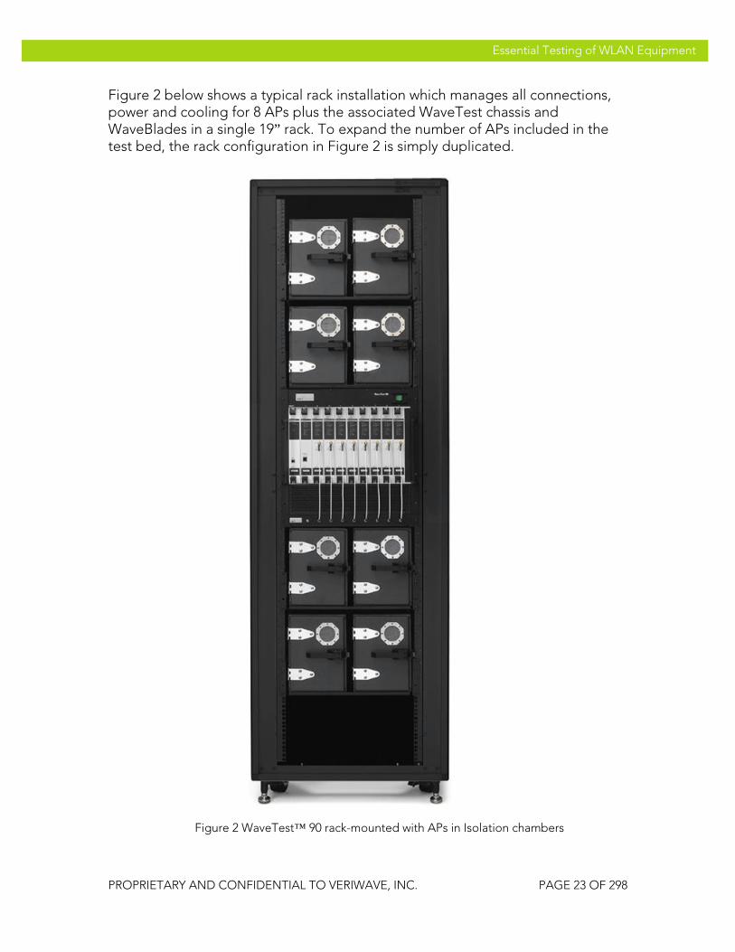
Figure 2 below shows a typical rack installation which manages all connections, power and cooling for 8 APs plus the associated WaveTest chassis and WaveBlades in a single 19” rack. To expand the number of APs included in the test bed, the rack configuration in Figure 2 is simply duplicated.
Figure 2 WaveTest™ 90 rack-mounted with APs in Isolation chambers
VeriWave, Inc. Essential Testing of WLAN Equipment
PROPRIETARY AND CONFIDENTIAL TO VERIWAVE, INC. PAGE 24 OF 298
Essential Testing of WLAN Equipment
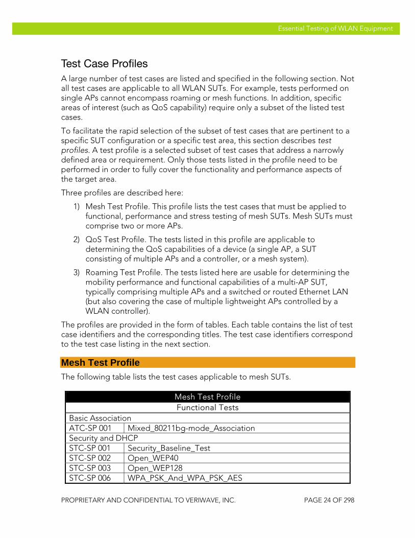
Test Case Profiles A large number of test cases are listed and specified in the following section. Not all test cases are applicable to all WLAN SUTs. For example, tests performed on single APs cannot encompass roaming or mesh functions. In addition, specific areas of interest (such as QoS capability) require only a subset of the listed test cases.
To facilitate the rapid selection of the subset of test cases that are pertinent to a specific SUT configuration or a specific test area, this section describes test profiles. A test profile is a selected subset of test cases that address a narrowly defined area or requirement. Only those tests listed in the profile need to be performed in order to fully cover the functionality and performance aspects of the target area.
Three profiles are described here:
1) Mesh Test Profile. This profile lists the test cases that must be applied to functional, performance and stress testing of mesh SUTs. Mesh SUTs must comprise two or more APs.
2) QoS Test Profile. The tests listed in this profile are applicable to determining the QoS capabilities of a device (a single AP, a SUT consisting of multiple APs and a controller, or a mesh system).
3) Roaming Test Profile. The tests listed here are usable for determining the mobility performance and functional capabilities of a multi-AP SUT, typically comprising multiple APs and a switched or routed Ethernet LAN (but also covering the case of multiple lightweight APs controlled by a WLAN controller).
The profiles are provided in the form of tables. Each table contains the list of test case identifiers and the corresponding titles. The test case identifiers correspond to the test case listing in the next section.
Mesh Test Profile The following table lists the test cases applicable to mesh SUTs.
Mesh Test Profile Functional Tests
Basic Association ATC-SP 001 Mixed_80211bg-mode_Association Security and DHCP STC-SP 001 Security_Baseline_Test STC-SP 002 Open_WEP40 STC-SP 003 Open_WEP128 STC-SP 006 WPA_PSK_And_WPA_PSK_AES

VeriWave, Inc. Essential Testing of WLAN Equipment
PROPRIETARY AND CONFIDENTIAL TO VERIWAVE, INC. PAGE 25 OF 298
Essential Testing of WLAN Equipment
Mesh Test Profile STC-SP 007 WPA2_PSK_And_WPA2_PSK_TKIP Basic Forwarding BTC-SP 001 Upstream_80211g_Packet_Loss_Sweep BTC-SP 002 Downstream_80211g_Packet_Loss_Sweep BTC-SP 003 Bidirectional_80211g_Packet_Loss_Sweep Power Save PTC-SP 001 Power_Save_Baseline_CAM_Test PTC-SP 004 Power-Save_APSD PTC-SP 005 Power-Save_Mixed_3 PTC-SP 006 Power-Save_Mixed_5 PTC-SP 007 Power-Save_Transition_2 QoS QTC-SP 001 Basic_WMM_Association QTC-SP 002 Single_Station_Downstream_Fairness QTC-SP 003 Single_Station_Downstream_Priority QTC-SP 004 Multi_Station_Downstream_Fairness QTC-SP 005 Multi_Station_Downstream_Priority QTC-SP 006 Multi_Station_Upstream_Fairness QTC-SP 007 Multi_Station_Upstream_Priority QTC-SP 008 Legacy_QoS_Coexistence QTC-SP 013 Call_Admission_Control_Mesh Denial of Service Attack Resilience DTC-SP 001 Authentication_Flood_Protection DTC-SP 002 Deauthentication_Flood_Protection DTC-SP 003 Association_Flood_Protection DTC-SP 004 Broadcast-Probe_Flood_Protection DTC-SP 005 Disassociation_Flood_Protection DTC-SP 006 Reassociation-Request_Flood_Protection DTC-SP 007 Invalid_SSID_Association_Protection DTC-SP 008 Invalid_Beacon_Protection DTC-SP 009 Invalid_Power-Save-Poll_Protection DTC-SP 010 Bad_Data-Frame_Protection
Performance and Capacity Tests Client/Call Capacity CBTC-SP 003 Max_Mesh_Client_Capacity_DHCP CBTC-SP 004 Max_Mesh_VoIP_Call_Capacity_DHCP Rate vs. Range CBTC-SP 010 Rate_vs_Range_80211b CBTC-SP 011 Rate_vs_Range_80211g Maximum Stateful TCP Goodput PBTC-SP 050 Upstream_80211g_Max_TCP_Goodput PBTC-SP 051 Downstream_80211g_Max_TCP_Goodput

VeriWave, Inc. Essential Testing of WLAN Equipment
PROPRIETARY AND CONFIDENTIAL TO VERIWAVE, INC. PAGE 26 OF 298
Essential Testing of WLAN Equipment
Mesh Test Profile Roaming Performance PBTC-SP 070 Roaming_Delay_80211g_Baseline PBTC-SP 072 Roaming_Delay_80211g_Secure PBTC-SP 074 Roaming_Delay_80211g_DHCP Mesh Per-Hop and Aggregate Throughput PBTC-SP 100 Upstream_UDP_Per-Hop_Throughput PBTC-SP 101 Downstream_UDP_Per-Hop_Throughput PBTC-SP 102 Bidirectional_UDP_Per-Hop_Throughput PBTC-SP 103 Upstream_TCP_Per-Hop_Throughput PBTC-SP 104 Downstream_TCP_Per-Hop_Throughput PBTC-SP 105 Bidirectional_TCP_Per-Hop_Throughput PBTC-SP 106 Upstream_UDP_Aggregate_Throughput PBTC-SP 107 Downstream_UDP_Aggregate_Throughput PBTC-SP 108 Bidirectional_UDP_Aggregate_Throughput PBTC-SP 109 Upstream_TCP_Aggregate_Throughput PBTC-SP 110 Downstream_TCP_Aggregate_Throughput PBTC-SP 111 Bidirectional_TCP_Aggregate_Throughput Mesh Per-Hop and Aggregate Packet Latency PBTC-SP 140 Upstream_UDP_Per-Hop_Latency PBTC-SP 141 Downstream_UDP_Per-Hop_Latency PBTC-SP 142 Upstream_UDP_Aggregate_Latency PBTC-SP 143 Downstream_UDP_Aggregate_Latency Quality Of Service PBTC-SP 160 Basic_QoS_Service_Differentiation_2Levels PBTC-SP 161 Basic_QoS_Service_Differentiation_4Levels PBTC-SP 162 VoIP_SLA_Assurance PBTC-SP 163 VoIP_Roaming_80211g Multicast PBTC-SP 180 Multicast_Forwarding_Rate PBTC-SP 181 Multicast_Latency_And_Jitter
System/Stress Tests System Resiliency and Availability OFTC-SP 001 Mesh_Recovery Traffic Variation TVTC-SP 001 Data_Load_Isolation TVTC-SP 002 Roaming_Isolation_Network WiMix Tests WMTC-SP 001
WiMix_Triple_Play_Unicast
WMTC-SP 002
WiMix_Triple_Play_Multicast
Mesh Interference Effects

VeriWave, Inc. Essential Testing of WLAN Equipment
PROPRIETARY AND CONFIDENTIAL TO VERIWAVE, INC. PAGE 27 OF 298
Essential Testing of WLAN Equipment
Mesh Test Profile IETC-SP 001 Mesh_Interference_Reroute IETC-SP 002 Mesh_UDP_Throughput_Interference_Impact IETC-SP 003 Mesh_Latency_Interference_Impact Traffic Stress TSTC-SP 001 Traffic_Stress Roaming Stress RSTC-SP 001 VoIP_Roaming_Stress Connection Stress CSTC-SP 001 Client_Connection_Stress CSTC-SP 002 Client_Connection_Data_Overload_Stress
QoS Test Profile The following table lists the test cases applicable to testing the WMM/802.11e QoS and APSD Power Save capabilities of an AP or a SUT.
QoS Test Profile Functional Tests
QoS Power Save PTC-SP 001 Power_Save_Baseline_CAM_Test PTC-SP 004 Power-Save_APSD PTC-SP 005 Power-Save_Mixed_3 PTC-SP 006 Power-Save_Mixed_5 PTC-SP 007 Power-Save_Transition_2 QoS QTC-SP 001 Basic_WMM_Association QTC-SP 002 Single_Station_Downstream_Fairness QTC-SP 003 Single_Station_Downstream_Priority QTC-SP 004 Multi_Station_Downstream_Fairness QTC-SP 005 Multi_Station_Downstream_Priority QTC-SP 006 Multi_Station_Upstream_Fairness QTC-SP 007 Multi_Station_Upstream_Priority QTC-SP 008 Legacy_QoS_Coexistence QTC-SP 009 Basic_Call_Admission_Control QTC-SP 010 Call_Admission_Control_Denial_PHY_Rate QTC-SP 011 Call_Admission_Control_Denial_Utilization QTC-SP 012 Call_Admission_Control_Codec_Type QTC-SP 013 Call_Admission_Control_Mesh
Performance and Capacity Tests Client/Call Capacity CBTC-SP 002 Max_VoIP_Call_Capacity_DHCP CBTC-SP 004 Max_Mesh_VoIP_Call_Capacity_DHCP Packet Latency

VeriWave, Inc. Essential Testing of WLAN Equipment
PROPRIETARY AND CONFIDENTIAL TO VERIWAVE, INC. PAGE 28 OF 298
Essential Testing of WLAN Equipment
QoS Test Profile PBTC-SP 020 Upstream_80211g_Packet_Latency PBTC-SP 021 Downstream_80211g_Packet_Latency PBTC-SP 022 Upstream_80211a_Packet_Latency PBTC-SP 023 Downstream_80211a_Packet_Latency Quality Of Service PBTC-SP 160 Basic_QoS_Service_Differentiation_2Levels PBTC-SP 161 Basic_QoS_Service_Differentiation_4Levels PBTC-SP 162 VoIP_SLA_Assurance PBTC-SP 163 VoIP_Roaming_80211g PBTC-SP 164 VoIP_Roaming_80211a Multicast PBTC-SP 181 Multicast_Latency_And_Jitter
System/Stress Tests WiMix Tests WMTC-SP 001
WiMix_Triple_Play_Unicast
WMTC-SP 002
WiMix_Triple_Play_Multicast
Roaming Stress RSTC-SP 001 VoIP_Roaming_Stress
Roaming Test Profile The following table lists the test cases applicable to testing the roaming functionality and performance of a multi-AP SUT.
Roaming Test Profile Performance and Capacity Tests
Roaming Performance PBTC-SP 070 Roaming_Delay_80211g_Baseline PBTC-SP 071 Roaming_Delay_80211a_Baseline PBTC-SP 072 Roaming_Delay_80211g_Secure PBTC-SP 073 Roaming_Delay_80211a_Secure PBTC-SP 074 Roaming_Delay_80211g_DHCP PBTC-SP 075 Roaming_Delay_80211a_DHCP PBTC-SP 076 Roaming_Delay_80211g_MultiSSID PBTC-SP 077 Roaming_Delay_80211a_MultiSSID Quality Of Service PBTC-SP 163 VoIP_Roaming_80211g PBTC-SP 164 VoIP_Roaming_80211a
System/Stress Tests Traffic Variation TVTC-SP 002 Roaming_Isolation_Network

VeriWave, Inc. Essential Testing of WLAN Equipment
PROPRIETARY AND CONFIDENTIAL TO VERIWAVE, INC. PAGE 29 OF 298
Essential Testing of WLAN Equipment
Test Plan
Functional Verification This section covers test cases that are essential to qualify the various functional capabilities supported by the SUT, before embarking on more comprehensive performance measurements. Test case results either indicate that the specific functional module is functioning as expected, or indicates a failure condition that must be fixed before proceeding.
Note that while the tests in this section are comprehensive, passing results on all of these individual functional test cases does not necessarily imply that the SUT is capable of operating in deployment conditions. The relevant performance, system and stress tests (as called out by the appropriate equipment profiles) must also be conducted in order to ensure that the SUT can be safely and effectively deployed.
Association
The following tests verify the general association functionality of the SUT. The tests span all valid operating channels as well as mixed-mode functioning. Successful completion of these tests indicate that the SUT is capable of being discovered and associated to by clients under various circumstances. Failure of any of these basic tests indicates a potential issue with client connection capability in deployed networks and should be addressed before conducting any further tests.
The association tests are performed with different frame sizes, numbers of clients, and probe functionality (i.e., passive or active scanning AP discovery methods) to ensure that successful association can be achieved under many different client behaviors.
ATC-SP 001 Mixed_80211bg-mode_Association
Title Verify concurrent association of mixed IEEE 802.11b and IEEE 802.11g clients in the same BSS
Purpose
Tests the SUT for support of a mixed IEEE 802.11g and IEEE 802.11b (legacy) client environment by performing association with one or more IEEE 802.11g client stations and one or more IEEE 802.11b client stations. Test traffic is sent from each associated client to the SUT in order to verify successful association.
SUT Feature(s) Mixed IEEE 802.11b & IEEE 802.11g client support
Roaming Stress RSTC-SP 001 VoIP_Roaming_Stress

VeriWave, Inc. Essential Testing of WLAN Equipment
PROPRIETARY AND CONFIDENTIAL TO VERIWAVE, INC. PAGE 30 OF 298
Essential Testing of WLAN Equipment
Tested
Requirement(s)
• WaveApps application running on host PC • WT-90 or WT-20 chassis with 1xWi-Fi WaveBlades
and 1xEthernet WaveBlade • SUT with AP set up to operate in the 2.4 GHz bands
(note: more than one AP may be used, but each AP must be presented with a mixture of IEEE 802.11b and IEEE 802.11g clients)
• Static IP addressing configured in the SUT
Test Setup
• Connect the Wi-Fi WaveBlade to the SUT via RF cables
• Configure the SUT to open-system authentication mode
• Set Basic Rate Set on the port/AP of SUT to 1Mbps, 2Mbps, 5.5Mbps, 6Mbps, 11Mbps, 12Mbps, 24Mbps
• Set IEEE 802.11b client flow PHY rate to 11 Mb/s and management (i.e., connection) PHY rate to 1 Mb/s; set IEEE 802.11g client flow PHY rate to 54 Mb/s and management PHY rate to 6 Mb/s
• Set offered test traffic load to 100 frames/second • Set client association timeout to 20 seconds and
permit 2 retries for failed associations • Run test using IEEE 802.11b/g channels (1, 2, 3, 4, 5,
6, 7, 8, 9, 10, 11) • Run test with UDP frame sizes: 88, 1518 bytes • Run test with 1 and 10 clients per port • Run test with unicast active scan (probing),
broadcast active scan (probing), and passive scan (no probing) client functionality
Procedure
1. Launch the WaveApps application
2. Select the Packet Loss Test under the IEEE 802.11.2 Benchmark Test Suite
3. Select the test port to use for the test and set the initial channel to channel 1
4. Select SSID and configure two sets of clients on this SSID with open authentication with no encryption, and static IP addresses; one set is configured to use IEEE 802.11g rates (54 Mb/s and 6 Mb/s), and the

VeriWave, Inc. Essential Testing of WLAN Equipment
PROPRIETARY AND CONFIDENTIAL TO VERIWAVE, INC. PAGE 31 OF 298
Essential Testing of WLAN Equipment
other set is configured to use IEEE 802.11b rates (11 Mb/s and 1 Mb/s) with IEEE 802.11b-only mode being set on the latter
5. Set client probe behavior to broadcast probing before association
6. Create an Ethernet client group on the correct port(s) with the initial number of Ethernet clients set to 1
7. Set the initial number of Wi-Fi clients to 1
8. Select the frame sizes as 88 and 1518 bytes, and UDP traffic type
9. Set the ILOAD to 100 frames/second
10. Select Wireless to Ethernet (one-to-one, upstream) mapping and a trial duration of 30 seconds
11. Run the test
12. Wait until test completes
13. Collect report and results data
14. Repeat steps 6 to 13 with 10 clients
15. Repeat steps 6 to 14 with channels 2, 3, 4, 5, 6, 7, 8, 9, 10, 11
16. Repeat steps 6 to 15 with unicast probing before association
17. Repeat steps 6 to 15 with no probing before association (passive scanning)
Test Priority Mandatory
Test Type General
Pass/Fail Criteria The Wi-Fi client(s) should successfully associate with the SUT and pass traffic to the Ethernet client with zero loss on all channels and under all test conditions.
ATC-SP 002 Basic_80211a-mode_Association
Title Verify basic association on all channels in IEEE 802.11a mode
Purpose Tests the SUT for basic support of IEEE 802.11a by performing association with one or more client stations on all valid IEEE 802.11a channels. Test traffic is sent

VeriWave, Inc. Essential Testing of WLAN Equipment
PROPRIETARY AND CONFIDENTIAL TO VERIWAVE, INC. PAGE 32 OF 298
Essential Testing of WLAN Equipment
from each associated client to the SUT in order to verify successful association. This test is run only if the SUT supports IEEE 802.11a operating mode.
SUT Feature(s) Tested
IEEE 802.11a client support
Requirement(s)
• WaveApps application running on host PC • WT-90 or WT-20 chassis with 1xWi-Fi WaveBlade
and 1xEthernet WaveBlade • SUT set up to operate in the IEEE 802.11a band • Static IP addressing configured in the SUT
Test Setup
• Connect the Wi-Fi WaveBlade to SUT via RF cables • Configure the SUT to open-system authentication
mode • Set Basic Rate Set on SUT to 6Mbps, 12Mbps,
24Mbps • Set client flow PHY rate to 54 Mb/s and
management (i.e., connection) PHY rate to 6 Mb/s • Set offered test traffic load to 100 frames/second • Set client association timeout to 20 seconds and
permit 2 retries for failed associations • Run test using IEEE 802.11a channels (36, 40, 44, 48,
52, 56, 60, 64, 149, 153, 157, 161) • Run test with UDP frame sizes: 88, 1518 bytes • Run test with 1 and 10 clients • Run test with unicast active scan (probing),
broadcast active scan (probing), and passive scan (no probing) client functionality
Procedure
1. Launch the WaveApps application
2. Select the Packet Loss Test under the IEEE 802.11.2 Benchmark Test Suite
3. Select the test port (i.e., AP in SUT) to use for the test and set the initial channel to channel 36
4. Select SSID and configure the client(s) to open authentication with no encryption and static IP address(es)
5. Set client probe behavior to broadcast probing before association
6. Create an Ethernet client group on the correct
VeriWave, Inc. Essential Testing of WLAN Equipment
PROPRIETARY AND CONFIDENTIAL TO VERIWAVE, INC. PAGE 33 OF 298
Essential Testing of WLAN Equipment
port(s) with the initial number of Ethernet clients set to 1
7. Set the initial number of Wi-Fi clients to 1
8. Select the frame sizes as 88 and 1518 bytes, and UDP traffic type
9. Set the ILOAD to 100 frames/second
10. Select Wireless to Ethernet (one-to-one, upstream) mapping and a trial duration of 30 seconds
11. Run the test
12. Wait until test completes
13. Collect report and results data
14. Repeat steps 4 to 13 with 10 clients
15. Repeat steps 4 to 14 with channels 40, 44, 48, 52, 56, 60, 64, 149, 153, 157, 161
16. Repeat steps 4 to 15 with unicast probing before association
17. Repeat steps 4 to 15 with no probing before association (passive scanning)
Test Priority Mandatory
Test Type General
Pass/Fail Criteria
The Wi-Fi client(s) should successfully associate with the SUT and pass traffic to the Ethernet client with zero loss on all IEEE 802.11a-band channels and under all test conditions.
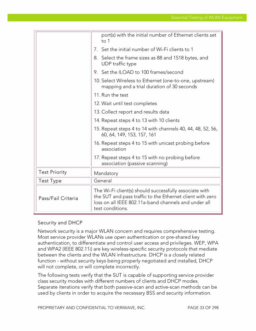
Security and DHCP
Network security is a major WLAN concern and requires comprehensive testing. Most service provider WLANs use open authentication or pre-shared key authentication, to differentiate and control user access and privileges. WEP, WPA and WPA2 (IEEE 802.11i) are key wireless-specific security protocols that mediate between the clients and the WLAN infrastructure. DHCP is a closely related function - without security keys being properly negotiated and installed, DHCP will not complete, or will complete incorrectly.
The following tests verify that the SUT is capable of supporting service provider class security modes with different numbers of clients and DHCP modes. Separate iterations verify that both passive-scan and active-scan methods can be used by clients in order to acquire the necessary BSS and security information.

VeriWave, Inc. Essential Testing of WLAN Equipment
PROPRIETARY AND CONFIDENTIAL TO VERIWAVE, INC. PAGE 34 OF 298
Essential Testing of WLAN Equipment
The tests are assumed to be performed using the 2.4 GHz band (with an IEEE 802.11b/g SUT port) but can be applied to the 5 GHz band if desired, by changing the operating channel(s).
STC-SP 001 Security_Baseline_Test
Title Record baseline open authentication behavior with no encryption
Purpose
Test the SUT for connectivity to WLAN clients using open authentication support without encryption. This test serves as a baseline for the subsequent secure connectivity tests. Test traffic is sent from each associated client to the SUT in order to verify successful connectivity establishment.
SUT Feature(s) Tested
Baseline insecure connectivity, DHCP with no security
Requirement(s)
• WaveApps application running on host PC • WT-90 or WT-20 chassis with 1xWi-Fi WaveBlade
and 1xEthernet WaveBlade • SUT set up to operate in the IEEE 802.11b/g band,
with static IP addressing as well as DHCP enabled • DHCP server connected to Ethernet port of SUT
Test Setup
• Connect the Wi-Fi WaveBlade to SUT via RF cables • Configure the SUT to open-system authentication
mode with no cipher, and to allow clients to use static IP addresses as well as DHCP
• Set Basic Rate Set on SUT to 1Mbps, 2 Mbps, 5.5Mbps, 6Mbps, 11Mbps, 12Mbps, 24Mbps
• Set client flow PHY rate to 54 Mb/s and management (i.e., connection) PHY rate to 6 Mb/s
• Set offered test traffic load to 100 frames/second • Set client association timeout to 20 seconds and
permit 2 retries for failed associations • Set channel to 1 (2.4 GHz band) • Run test with UDP frame sizes: 88, 512, 1518 bytes • Run test with 1 and 10 clients • Run test with active scan (broadcast probing) and
passive scan (no probing) client behavior
Procedure 1. Launch the WaveApps application

VeriWave, Inc. Essential Testing of WLAN Equipment
PROPRIETARY AND CONFIDENTIAL TO VERIWAVE, INC. PAGE 35 OF 298
Essential Testing of WLAN Equipment
2. Select the Packet Loss Test under the IEEE 802.11.2 Benchmark Test Suite
3. Select the test port (i.e., AP in SUT) to use for the test and set the channel to 1
4. Select SSID and configure the client(s) to open authentication with no encryption
5. Configure the client to use static IP address(es)
6. Set client probe behavior to broadcast probing before association (active scanning)
7. Create an Ethernet client group on the correct port(s) with the initial number of Ethernet clients set to 1
8. Set the initial number of Wi-Fi clients to 1
9. Select the frame sizes as 88, 512 and 1518 bytes, and UDP traffic type
10. Set the ILOAD to 100 frames/second
11. Select Wireless to Ethernet (one-to-one, upstream) mapping and a trial duration of 30 seconds
12. Run the test
13. Wait until test completes
14. Collect report and results data
15. Repeat steps 4 to 14 with 10 clients
16. Repeat steps 4 to 15 with no probing before association (passive scanning)
17. Repeat steps 4 to 16 with DHCP being used by clients instead of static IP addresses
Test Priority Mandatory
Test Type Authentication
Pass/Fail Criteria
The Wi-Fi client(s) should successfully associate with the SUT and pass traffic to the Ethernet client with zero loss under all test conditions, and should also successfully acquire DHCP address(es) in the correct subnet(s).

VeriWave, Inc. Essential Testing of WLAN Equipment
PROPRIETARY AND CONFIDENTIAL TO VERIWAVE, INC. PAGE 36 OF 298
Essential Testing of WLAN Equipment
STC-SP 002 Open_WEP40
Title Verify support of WEP security with open authentication using 40-bit keys
Purpose
Test the SUT for connectivity to WLAN clients using open authentication support with WEP encryption and 40-bit key widths. Test traffic is sent from each associated client to the SUT in order to verify successful connectivity establishment including matching security parameters.
SUT Feature(s) Tested
WEP-40 with Open authentication, DHCP
Requirement(s)
• WaveApps application running on host PC • WT-90 or WT-20 chassis with 1xWi-Fi WaveBlade
and 1xEthernet WaveBlade • SUT set up to operate in the IEEE 802.11b/g band,
with static IP addressing as well as DHCP enabled • DHCP server connected to Ethernet port of SUT
Test Setup
• Connect the Wi-Fi WaveBlade to SUT via RF cables • Configure the SUT to open-system authentication
mode with WEP-40 encryption, and to allow clients to use static IP addresses as well as DHCP
• Configure 40-bit hex encryption key in SUT to ‘3031323334’
• Set Basic Rate Set on SUT to 1Mbps, 2 Mbps, 5.5Mbps, 6Mbps, 11Mbps, 12Mbps, 24Mbps
• Set client flow PHY rate to 54 Mb/s and management (i.e., connection) PHY rate to 6 Mb/s
• Set client security method to WEP-Open with 40-bit hex key of ‘3031323334’
• Set offered test traffic load to 100 frames/second • Set client association timeout to 20 seconds and
permit 2 retries for failed associations • Set channel to 1 (2.4 GHz band) • Run test with UDP frame sizes: 88, 512, 1518 bytes • Run test with 1 and 10 clients using the same
security parameters • Run test with active scan (broadcast probing) and
passive scan (no probing) client behavior

VeriWave, Inc. Essential Testing of WLAN Equipment
PROPRIETARY AND CONFIDENTIAL TO VERIWAVE, INC. PAGE 37 OF 298
Essential Testing of WLAN Equipment
Procedure
1. Launch the WaveApps application
2. Select the Packet Loss Test under the IEEE 802.11.2 Benchmark Test Suite
3. Select the test port (i.e., AP in SUT) to use for the test and set the channel to 1
4. Select SSID and configure the client(s) to use security parameters as indicated above
5. Configure the client to use static IP address(es)
6. Set client probe behavior to broadcast probing before association (active scanning)
7. Create an Ethernet client group on the correct port(s) with the initial number of Ethernet clients set to 1
8. Set the initial number of Wi-Fi clients to 1
9. Select the frame sizes as 88, 512 and 1518 bytes, and UDP traffic type
10. Set the ILOAD to 100 frames/second
11. Select Wireless to Ethernet (one-to-one, upstream) mapping and a trial duration of 30 seconds
12. Run the test
13. Wait until test completes
14. Collect report and results data
15. Repeat steps 4 to 14 with 10 clients
16. Repeat steps 4 to 15 with no probing before association (passive scanning)
17. Repeat steps 4 to 16 with DHCP being used by clients instead of static IP addresses
Test Priority Low
Test Type Authentication
Pass/Fail Criteria
The Wi-Fi client(s) should successfully associate with the SUT and pass traffic to the Ethernet client with zero loss under all test conditions, and should also successfully acquire DHCP address(es) in the correct subnet(s).

VeriWave, Inc. Essential Testing of WLAN Equipment
PROPRIETARY AND CONFIDENTIAL TO VERIWAVE, INC. PAGE 38 OF 298
Essential Testing of WLAN Equipment
STC-SP 003 Open_WEP128
Title Verify support of WEP security with open authentication using 128-bit keys
Purpose
Test the SUT for connectivity to WLAN clients using open authentication support with WEP encryption and 128-bit key widths. Test traffic is sent from each associated client to the SUT in order to verify successful connectivity establishment including matching security parameters.
NOTE: 128-bit keys are sometimes referred to as 104-bit keys
SUT Feature(s) Tested
WEP-128 with Open authentication, DHCP
Requirement(s)
• WaveApps application running on host PC • WT-90 or WT-20 chassis with 1xWi-Fi WaveBlade
and 1xEthernet WaveBlade • SUT set up to operate in the IEEE 802.11b/g band,
with static IP addressing as well as DHCP enabled • DHCP server connected to Ethernet port of SUT
Test Setup
• Connect the Wi-Fi WaveBlade to SUT via RF cables • Configure the SUT to open-system authentication
mode with WEP-40 encryption, and to allow clients to use static IP addresses as well as DHCP
• Configure 128-bit hex encryption key in SUT to ‘30313233343536373839303132’
• Set Basic Rate Set on SUT to 1Mbps, 2 Mbps, 5.5Mbps, 6Mbps, 11Mbps, 12Mbps, 24Mbps
• Set client flow PHY rate to 54 Mb/s and management (i.e., connection) PHY rate to 6 Mb/s
• Set client security method to WEP-Open with 128-bit hex key of ‘30313233343536373839303132’
• Set offered test traffic load to 100 frames/second • Set client association timeout to 20 seconds and
permit 2 retries for failed associations • Set channel to 1 (2.4 GHz band) • Run test with UDP frame sizes: 88, 512, 1518 bytes • Run test with 1 and 10 clients using the same
security parameters

VeriWave, Inc. Essential Testing of WLAN Equipment
PROPRIETARY AND CONFIDENTIAL TO VERIWAVE, INC. PAGE 39 OF 298
Essential Testing of WLAN Equipment
• Run test with active scan (broadcast probing) and passive scan (no probing) client behavior
Procedure
1. Launch the WaveApps application
2. Select the Packet Loss Test under the IEEE 802.11.2 Benchmark Test Suite
3. Select the test port (i.e., AP in SUT) to use for the test and set the channel to 1
4. Select SSID and configure the client(s) to use security parameters as indicated above
5. Configure the client to use static IP address(es)
6. Set client probe behavior to broadcast probing before association (active scanning)
7. Create an Ethernet client group on the correct port(s) with the initial number of Ethernet clients set to 1
8. Set the initial number of Wi-Fi clients to 1
9. Select the frame sizes as 88, 512 and 1518 bytes, and UDP traffic type
10. Set the ILOAD to 100 frames/second
11. Select Wireless to Ethernet (one-to-one, upstream) mapping and a trial duration of 30 seconds
12. Run the test
13. Wait until test completes
14. Collect report and results data
15. Repeat steps 4 to 14 with 10 clients
16. Repeat steps 4 to 15 with no probing before association (passive scanning)
17. Repeat steps 4 to 16 with DHCP being used by clients instead of static IP addresses
Test Priority Low
Test Type Authentication
Pass/Fail Criteria
The Wi-Fi client(s) should successfully associate with the SUT and pass traffic to the Ethernet client with zero loss under all test conditions, and should also successfully acquire DHCP address(es) in the correct

VeriWave, Inc. Essential Testing of WLAN Equipment
PROPRIETARY AND CONFIDENTIAL TO VERIWAVE, INC. PAGE 40 OF 298
Essential Testing of WLAN Equipment
subnet(s).
STC-SP 004 Shared-Key_WEP40
Title Verify support of WEP security with shared-key authentication using 40-bit keys
Purpose
Test the SUT for connectivity to WLAN clients using shared-key authentication support with WEP encryption and 40-bit key widths. Test traffic is sent from each associated client to the SUT in order to verify successful connectivity establishment including matching security parameters.
SUT Feature(s) Tested
WEP-40 with Shared-key authentication, DHCP
Requirement(s)
• WaveApps application running on host PC • WT-90 or WT-20 chassis with 1xWi-Fi WaveBlade
and 1xEthernet WaveBlade • SUT set up to operate in the IEEE 802.11b/g band,
with static IP addressing as well as DHCP enabled • DHCP server connected to Ethernet port of SUT
Test Setup
• Connect the Wi-Fi WaveBlade to SUT via RF cables • Configure the SUT to shared-key authentication
mode with WEP-40 encryption, and to allow clients to use static IP addresses as well as DHCP
• Configure 40-bit hex encryption key in SUT to ‘3031323334’
• Set Basic Rate Set on SUT to 1Mbps, 2 Mbps, 5.5Mbps, 6Mbps, 11Mbps, 12Mbps, 24Mbps
• Set client flow PHY rate to 54 Mb/s and management (i.e., connection) PHY rate to 6 Mb/s
• Set client security method to WEP-Shared with 40-bit hex key of ‘3031323334’
• Set offered test traffic load to 100 frames/second • Set client association timeout to 20 seconds and
permit 2 retries for failed associations • Set channel to 1 (2.4 GHz band) • Run test with UDP frame sizes: 88, 512, 1518 bytes • Run test with 1 and 10 clients using the same
security parameters

VeriWave, Inc. Essential Testing of WLAN Equipment
PROPRIETARY AND CONFIDENTIAL TO VERIWAVE, INC. PAGE 41 OF 298
Essential Testing of WLAN Equipment
• Run test with active scan (broadcast probing) and passive scan (no probing) client behavior
Procedure
1. Launch the WaveApps application
2. Select the Packet Loss Test under the IEEE 802.11.2 Benchmark Test Suite
3. Select the test port (i.e., AP in SUT) to use for the test and set the channel to 1
4. Select SSID and configure the client(s) to use security parameters as indicated above
5. Configure the client to use static IP address(es)
6. Set client probe behavior to broadcast probing before association (active scanning)
7. Create an Ethernet client group on the correct port(s) with the initial number of Ethernet clients set to 1
8. Set the initial number of Wi-Fi clients to 1
9. Select the frame sizes as 88, 512 and 1518 bytes, and UDP traffic type
10. Set the ILOAD to 100 frames/second
11. Select Wireless to Ethernet (one-to-one, upstream) mapping and a trial duration of 30 seconds
12. Run the test
13. Wait until test completes
14. Collect report and results data
15. Repeat steps 4 to 14 with 10 clients
16. Repeat steps 4 to 15 with no probing before association (passive scanning)
17. Repeat steps 4 to 16 with DHCP being used by clients instead of static IP addresses
Test Priority Low
Test Type Authentication
Pass/Fail Criteria
The Wi-Fi client(s) should successfully associate with the SUT and pass traffic to the Ethernet client with zero loss under all test conditions, and should also successfully acquire DHCP address(es) in the correct

VeriWave, Inc. Essential Testing of WLAN Equipment
PROPRIETARY AND CONFIDENTIAL TO VERIWAVE, INC. PAGE 42 OF 298
Essential Testing of WLAN Equipment
subnet(s).
STC-SP 005 Shared-Key_WEP128
Title Verify support of WEP security with shared-key authentication using 128-bit keys
Purpose
Test the SUT for connectivity to WLAN clients using open authentication support with WEP encryption and 128-bit key widths. Test traffic is sent from each associated client to the SUT in order to verify successful connectivity establishment including matching security parameters.
NOTE: 128-bit keys are sometimes referred to as 104-bit keys
SUT Feature(s) Tested
WEP-128 with Shared-key authentication, DHCP
Requirement(s)
• WaveApps application running on host PC • WT-90 or WT-20 chassis with 1xWi-Fi WaveBlade
and 1xEthernet WaveBlade • SUT set up to operate in the IEEE 802.11b/g band,
with static IP addressing as well as DHCP enabled • DHCP server connected to Ethernet port of SUT
Test Setup
• Connect the Wi-Fi WaveBlade to SUT via RF cables • Configure the SUT to shared-key authentication
mode with WEP-40 encryption, and to allow clients to use static IP addresses as well as DHCP
• Configure 128-bit hex encryption key in SUT to ‘30313233343536373839303132’
• Set Basic Rate Set on SUT to 1Mbps, 2 Mbps, 5.5Mbps, 6Mbps, 11Mbps, 12Mbps, 24Mbps
• Set client flow PHY rate to 54 Mb/s and management (i.e., connection) PHY rate to 6 Mb/s
• Set client security method to WEP-Shared with 128-bit hex key of ‘30313233343536373839303132’
• Set offered test traffic load to 100 frames/second • Set client association timeout to 20 seconds and
permit 2 retries for failed associations • Set channel to 1 (2.4 GHz band) • Run test with UDP frame sizes: 88, 512, 1518 bytes

VeriWave, Inc. Essential Testing of WLAN Equipment
PROPRIETARY AND CONFIDENTIAL TO VERIWAVE, INC. PAGE 43 OF 298
Essential Testing of WLAN Equipment
• Run test with 1 and 10 clients using the same security parameters
• Run test with active scan (broadcast probing) and passive scan (no probing) client behavior
Procedure
1. Launch the WaveApps application
2. Select the Packet Loss Test under the IEEE 802.11.2 Benchmark Test Suite
3. Select the test port (i.e., AP in SUT) to use for the test and set the channel to 1
4. Select SSID and configure the client(s) to use security parameters as indicated above
5. Configure the client to use static IP address(es)
6. Set client probe behavior to broadcast probing before association (active scanning)
7. Create an Ethernet client group on the correct port(s) with the initial number of Ethernet clients set to 1
8. Set the initial number of Wi-Fi clients to 1
9. Select the frame sizes as 88, 512 and 1518 bytes, and UDP traffic type
10. Set the ILOAD to 100 frames/second
11. Select Wireless to Ethernet (one-to-one, upstream) mapping and a trial duration of 30 seconds
12. Run the test
13. Wait until test completes
14. Collect report and results data
15. Repeat steps 4 to 14 with 10 clients
16. Repeat steps 4 to 15 with no probing before association (passive scanning)
17. Repeat steps 4 to 16 with DHCP being used by clients instead of static IP addresses
Test Priority Low
Test Type Authentication
Pass/Fail Criteria The Wi-Fi client(s) should successfully associate with
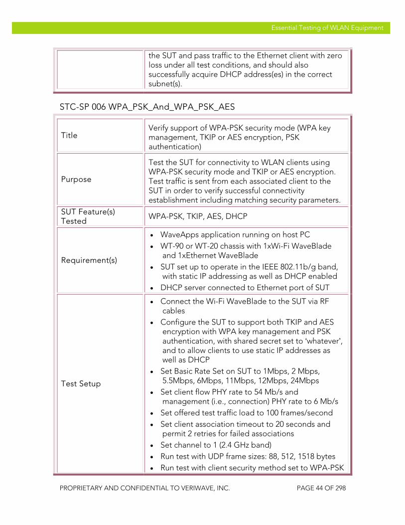
VeriWave, Inc. Essential Testing of WLAN Equipment
PROPRIETARY AND CONFIDENTIAL TO VERIWAVE, INC. PAGE 44 OF 298
Essential Testing of WLAN Equipment
the SUT and pass traffic to the Ethernet client with zero loss under all test conditions, and should also successfully acquire DHCP address(es) in the correct subnet(s).
STC-SP 006 WPA_PSK_And_WPA_PSK_AES
Title Verify support of WPA-PSK security mode (WPA key management, TKIP or AES encryption, PSK authentication)
Purpose
Test the SUT for connectivity to WLAN clients using WPA-PSK security mode and TKIP or AES encryption. Test traffic is sent from each associated client to the SUT in order to verify successful connectivity establishment including matching security parameters.
SUT Feature(s) Tested
WPA-PSK, TKIP, AES, DHCP
Requirement(s)
• WaveApps application running on host PC • WT-90 or WT-20 chassis with 1xWi-Fi WaveBlade
and 1xEthernet WaveBlade • SUT set up to operate in the IEEE 802.11b/g band,
with static IP addressing as well as DHCP enabled • DHCP server connected to Ethernet port of SUT
Test Setup
• Connect the Wi-Fi WaveBlade to the SUT via RF cables
• Configure the SUT to support both TKIP and AES encryption with WPA key management and PSK authentication, with shared secret set to ‘whatever’, and to allow clients to use static IP addresses as well as DHCP
• Set Basic Rate Set on SUT to 1Mbps, 2 Mbps, 5.5Mbps, 6Mbps, 11Mbps, 12Mbps, 24Mbps
• Set client flow PHY rate to 54 Mb/s and management (i.e., connection) PHY rate to 6 Mb/s
• Set offered test traffic load to 100 frames/second • Set client association timeout to 20 seconds and
permit 2 retries for failed associations • Set channel to 1 (2.4 GHz band) • Run test with UDP frame sizes: 88, 512, 1518 bytes • Run test with client security method set to WPA-PSK

VeriWave, Inc. Essential Testing of WLAN Equipment
PROPRIETARY AND CONFIDENTIAL TO VERIWAVE, INC. PAGE 45 OF 298
Essential Testing of WLAN Equipment
and WPA-PSK-AES, with shared secret set to ‘whatever’
• Run test with 1 and 10 clients using the same security parameters
• Run test with active scan (broadcast probing) and passive scan (no probing) client behavior
Procedure
1. Launch the WaveApps application
2. Select the Packet Loss Test under the IEEE 802.11.2 Benchmark Test Suite
3. Select the test port (i.e., AP in SUT) to use for the test and set the channel to 1
4. Select SSID and configure the client(s) to use security parameters as indicated above, starting with WPA-PSK
5. Configure the client to use static IP address(es)
6. Set client probe behavior to broadcast probing before association (active scanning)
7. Create an Ethernet client group on the correct port(s) with the initial number of Ethernet clients set to 1
8. Set the initial number of Wi-Fi clients to 1
9. Select the frame sizes as 88, 512 and 1518 bytes, and UDP traffic type
10. Set the ILOAD to 100 frames/second
11. Select Wireless to Ethernet (one-to-one, upstream) mapping and a trial duration of 30 seconds
12. Run the test
13. Wait until test completes
14. Collect report and results data
15. Repeat steps 4 to 14 with 10 clients
16. Repeat steps 4 to 15 with no probing before association (passive scanning)
17. Repeat steps 4 to 16 with DHCP being used by clients instead of static IP addresses
18. Repeat steps 4 to 17 with WPA-PSK-AES used as the security mode

VeriWave, Inc. Essential Testing of WLAN Equipment
PROPRIETARY AND CONFIDENTIAL TO VERIWAVE, INC. PAGE 46 OF 298
Essential Testing of WLAN Equipment
Test Priority Mandatory for WPA-PSK; Medium for WPA-PSK-AES
Test Type Authentication
Pass/Fail Criteria
The Wi-Fi client(s) should successfully associate with the SUT and pass traffic to the Ethernet client with zero loss under all test conditions, and should also successfully acquire DHCP address(es) in the correct subnet(s).
STC-SP 007 WPA2_PSK_And_WPA2_PSK_TKIP
Title Verify support of WPA2-PSK security mode (WPA2 key management, TKIP or AES encryption, PSK authentication)
Purpose
Test the SUT for connectivity to WLAN clients using WPA-PSK security mode and AES or TKIP encryption. Test traffic is sent from each associated client to the SUT in order to verify successful connectivity establishment including matching security parameters.
SUT Feature(s) Tested
WPA2-PSK, AES, TKIP, DHCP
Requirement(s)
• WaveApps application running on host PC • WT-90 or WT-20 chassis with 1xWi-Fi WaveBlade
and 1xEthernet WaveBlade • SUT set up to operate in the IEEE 802.11b/g band,
with static IP addressing as well as DHCP enabled • DHCP server connected to Ethernet port of SUT
Test Setup
• Connect the Wi-Fi WaveBlade to the SUT via RF cables
• Configure the SUT to support both TKIP and AES encryption with WPA2 key management and PSK authentication, with shared secret set to ‘whatever’, and to allow clients to use static IP addresses as well as DHCP
• Set Basic Rate Set on SUT to 1Mbps, 2 Mbps, 5.5Mbps, 6Mbps, 11Mbps, 12Mbps, 24Mbps
• Set client flow PHY rate to 54 Mb/s and management (i.e., connection) PHY rate to 6 Mb/s
• Set offered test traffic load to 100 frames/second • Set client association timeout to 20 seconds and
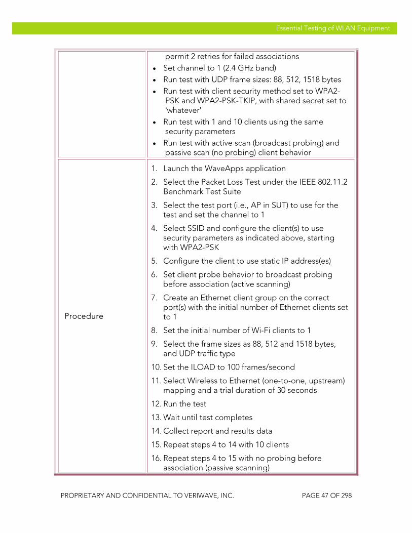
VeriWave, Inc. Essential Testing of WLAN Equipment
PROPRIETARY AND CONFIDENTIAL TO VERIWAVE, INC. PAGE 47 OF 298
Essential Testing of WLAN Equipment
permit 2 retries for failed associations • Set channel to 1 (2.4 GHz band) • Run test with UDP frame sizes: 88, 512, 1518 bytes • Run test with client security method set to WPA2-
PSK and WPA2-PSK-TKIP, with shared secret set to ‘whatever’
• Run test with 1 and 10 clients using the same security parameters
• Run test with active scan (broadcast probing) and passive scan (no probing) client behavior
Procedure
1. Launch the WaveApps application
2. Select the Packet Loss Test under the IEEE 802.11.2 Benchmark Test Suite
3. Select the test port (i.e., AP in SUT) to use for the test and set the channel to 1
4. Select SSID and configure the client(s) to use security parameters as indicated above, starting with WPA2-PSK
5. Configure the client to use static IP address(es)
6. Set client probe behavior to broadcast probing before association (active scanning)
7. Create an Ethernet client group on the correct port(s) with the initial number of Ethernet clients set to 1
8. Set the initial number of Wi-Fi clients to 1
9. Select the frame sizes as 88, 512 and 1518 bytes, and UDP traffic type
10. Set the ILOAD to 100 frames/second
11. Select Wireless to Ethernet (one-to-one, upstream) mapping and a trial duration of 30 seconds
12. Run the test
13. Wait until test completes
14. Collect report and results data
15. Repeat steps 4 to 14 with 10 clients
16. Repeat steps 4 to 15 with no probing before association (passive scanning)
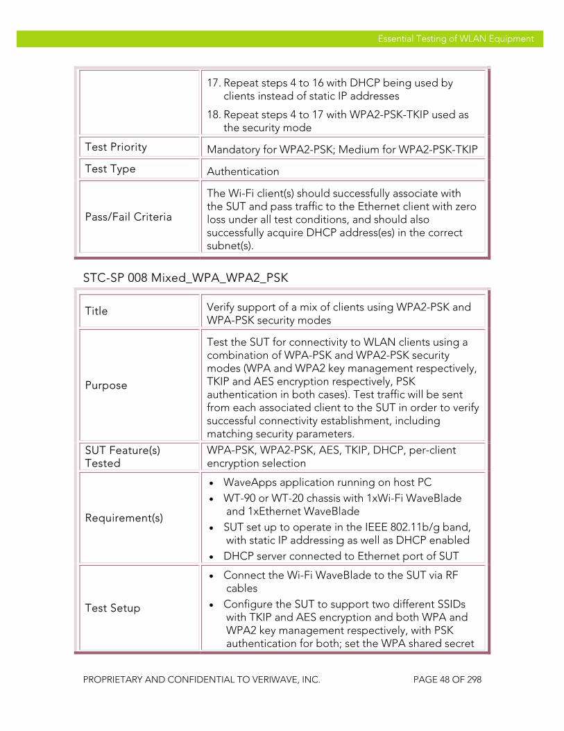
VeriWave, Inc. Essential Testing of WLAN Equipment
PROPRIETARY AND CONFIDENTIAL TO VERIWAVE, INC. PAGE 48 OF 298
Essential Testing of WLAN Equipment
17. Repeat steps 4 to 16 with DHCP being used by clients instead of static IP addresses
18. Repeat steps 4 to 17 with WPA2-PSK-TKIP used as the security mode
Test Priority Mandatory for WPA2-PSK; Medium for WPA2-PSK-TKIP
Test Type Authentication
Pass/Fail Criteria
The Wi-Fi client(s) should successfully associate with the SUT and pass traffic to the Ethernet client with zero loss under all test conditions, and should also successfully acquire DHCP address(es) in the correct subnet(s).
STC-SP 008 Mixed_WPA_WPA2_PSK
Title Verify support of a mix of clients using WPA2-PSK and WPA-PSK security modes
Purpose
Test the SUT for connectivity to WLAN clients using a combination of WPA-PSK and WPA2-PSK security modes (WPA and WPA2 key management respectively, TKIP and AES encryption respectively, PSK authentication in both cases). Test traffic will be sent from each associated client to the SUT in order to verify successful connectivity establishment, including matching security parameters.
SUT Feature(s) Tested
WPA-PSK, WPA2-PSK, AES, TKIP, DHCP, per-client encryption selection
Requirement(s)
• WaveApps application running on host PC • WT-90 or WT-20 chassis with 1xWi-Fi WaveBlade
and 1xEthernet WaveBlade • SUT set up to operate in the IEEE 802.11b/g band,
with static IP addressing as well as DHCP enabled • DHCP server connected to Ethernet port of SUT
Test Setup
• Connect the Wi-Fi WaveBlade to the SUT via RF cables
• Configure the SUT to support two different SSIDs with TKIP and AES encryption and both WPA and WPA2 key management respectively, with PSK authentication for both; set the WPA shared secret
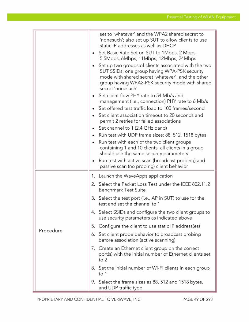
VeriWave, Inc. Essential Testing of WLAN Equipment
PROPRIETARY AND CONFIDENTIAL TO VERIWAVE, INC. PAGE 49 OF 298
Essential Testing of WLAN Equipment
set to ‘whatever’ and the WPA2 shared secret to ‘nonesuch’; also set up SUT to allow clients to use static IP addresses as well as DHCP
• Set Basic Rate Set on SUT to 1Mbps, 2 Mbps, 5.5Mbps, 6Mbps, 11Mbps, 12Mbps, 24Mbps
• Set up two groups of clients associated with the two SUT SSIDs; one group having WPA-PSK security mode with shared secret ‘whatever’, and the other group having WPA2-PSK security mode with shared secret ‘nonesuch’
• Set client flow PHY rate to 54 Mb/s and management (i.e., connection) PHY rate to 6 Mb/s
• Set offered test traffic load to 100 frames/second • Set client association timeout to 20 seconds and
permit 2 retries for failed associations • Set channel to 1 (2.4 GHz band) • Run test with UDP frame sizes: 88, 512, 1518 bytes • Run test with each of the two client groups
containing 1 and 10 clients; all clients in a group should use the same security parameters
• Run test with active scan (broadcast probing) and passive scan (no probing) client behavior
Procedure
1. Launch the WaveApps application
2. Select the Packet Loss Test under the IEEE 802.11.2 Benchmark Test Suite
3. Select the test port (i.e., AP in SUT) to use for the test and set the channel to 1
4. Select SSIDs and configure the two client groups to use security parameters as indicated above
5. Configure the client to use static IP address(es)
6. Set client probe behavior to broadcast probing before association (active scanning)
7. Create an Ethernet client group on the correct port(s) with the initial number of Ethernet clients set to 2
8. Set the initial number of Wi-Fi clients in each group to 1
9. Select the frame sizes as 88, 512 and 1518 bytes, and UDP traffic type
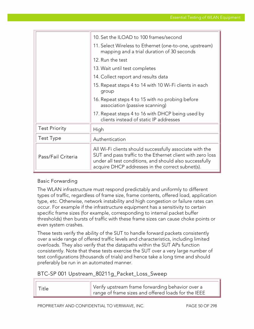
VeriWave, Inc. Essential Testing of WLAN Equipment
PROPRIETARY AND CONFIDENTIAL TO VERIWAVE, INC. PAGE 50 OF 298
Essential Testing of WLAN Equipment
10. Set the ILOAD to 100 frames/second
11. Select Wireless to Ethernet (one-to-one, upstream) mapping and a trial duration of 30 seconds
12. Run the test
13. Wait until test completes
14. Collect report and results data
15. Repeat steps 4 to 14 with 10 Wi-Fi clients in each group
16. Repeat steps 4 to 15 with no probing before association (passive scanning)
17. Repeat steps 4 to 16 with DHCP being used by clients instead of static IP addresses
Test Priority High
Test Type Authentication
Pass/Fail Criteria
All Wi-Fi clients should successfully associate with the SUT and pass traffic to the Ethernet client with zero loss under all test conditions, and should also successfully acquire DHCP addresses in the correct subnet(s).
Basic Forwarding
The WLAN infrastructure must respond predictably and uniformly to different types of traffic, regardless of frame size, frame contents, offered load, application type, etc. Otherwise, network instability and high congestion or failure rates can occur. For example if the infrastructure equipment has a sensitivity to certain specific frame sizes (for example, corresponding to internal packet buffer thresholds) then bursts of traffic with these frame sizes can cause choke points or even system crashes.
These tests verify the ability of the SUT to handle forward packets consistently over a wide range of offered traffic levels and characteristics, including limited overloads. They also verify that the datapaths within the SUT APs function consistently. Note that these tests exercise the SUT over a very large number of test configurations (thousands of trials) and hence take a long time and should preferably be run in an automated manner.
BTC-SP 001 Upstream_80211g_Packet_Loss_Sweep
Title Verify upstream frame forwarding behavior over a range of frame sizes and offered loads for the IEEE

VeriWave, Inc. Essential Testing of WLAN Equipment
PROPRIETARY AND CONFIDENTIAL TO VERIWAVE, INC. PAGE 51 OF 298
Essential Testing of WLAN Equipment
802.11g SUT datapaths
Purpose
Test the SUT to ensure that it processes and forwards wireless-to-Ethernet frames uniformly regardless of the specific frame size or the specific traffic load that is presented to it. Test traffic is injected into all of the SUT ports in the upstream direction and a sweep is performed over all legal frame sizes and a large number of offered loads. When plotted on a graph, the results will clearly indicate any anomalies or forwarding performance issues.
SUT Feature(s) Tested
Uniform traffic handling datapath, anomalous forwarding performance, instabilities
Requirement(s)
• WaveApps application running on host PC • WT-90 or WT-20 chassis with Wi-Fi WaveBlade(s)
and Ethernet WaveBlade(s) • SUT set up to support UDP traffic with static IP
addressing • SUT configured with IEEE 802.11g APs
Test Setup
• Configure the SUT with open-system authentication mode
• Set Basic Rate Set on SUT to 1Mbps, 2Mbps, 5.5Mbps, 6Mbps, 11Mbps, 12Mbps, 24Mbps
• Set client PHY rate to 54 Mb/s in IEEE 802.11g-only mode
• Run test with no encryption, TKIP and AES-CCMP • Run test with all UDP frame sizes ranging from 88
bytes to 1518 bytes inclusive in 1 byte steps (1431 values)
• Run test with 1 and 10 clients per AP • Run test with intended load (ILOAD) values ranging
from 1000 to 7000 frames/second (inclusive) per AP in 2000 byte steps (4 values).
Procedure
1. Launch the WaveApps application
2. Select the Packet Loss Test under the IEEE 802.11.2 Benchmark Test Suite
3. Select the test port(s) (i.e., APs) to use for the test, and note the number of APs as N
4. Select SSID and configure the client(s) to open authentication with no encryption and to use static
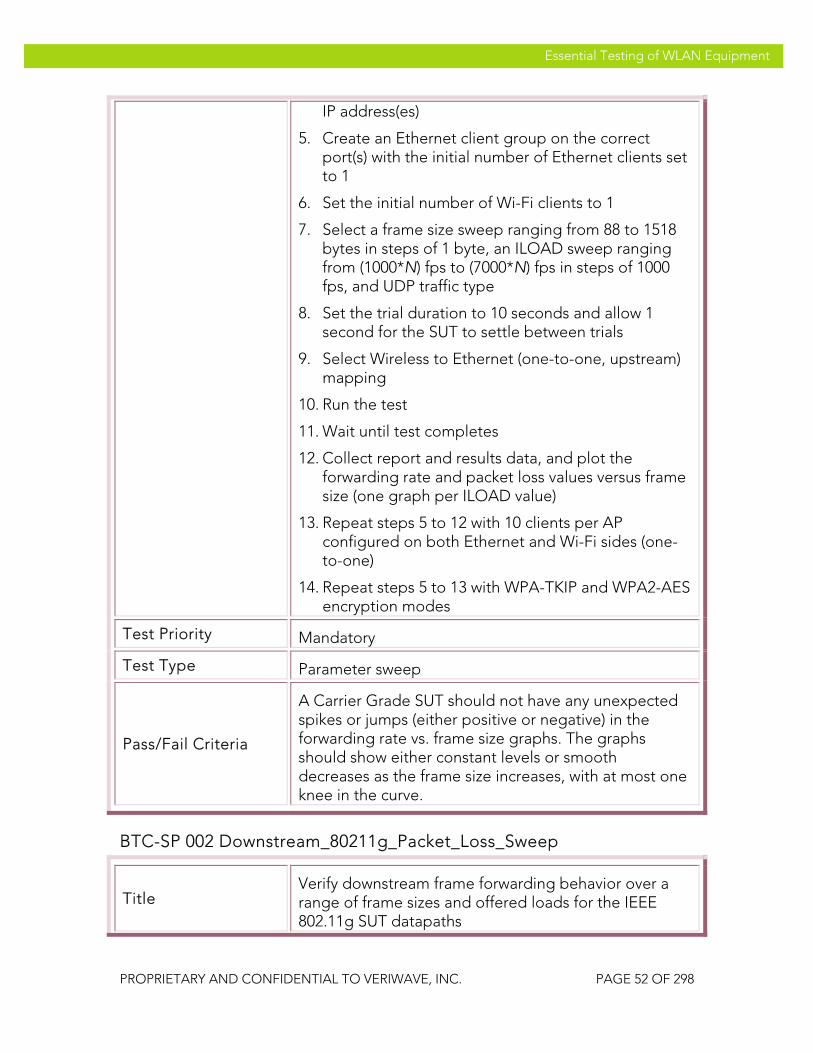
VeriWave, Inc. Essential Testing of WLAN Equipment
PROPRIETARY AND CONFIDENTIAL TO VERIWAVE, INC. PAGE 52 OF 298
Essential Testing of WLAN Equipment
IP address(es)
5. Create an Ethernet client group on the correct port(s) with the initial number of Ethernet clients set to 1
6. Set the initial number of Wi-Fi clients to 1
7. Select a frame size sweep ranging from 88 to 1518 bytes in steps of 1 byte, an ILOAD sweep ranging from (1000*N) fps to (7000*N) fps in steps of 1000 fps, and UDP traffic type
8. Set the trial duration to 10 seconds and allow 1 second for the SUT to settle between trials
9. Select Wireless to Ethernet (one-to-one, upstream) mapping
10. Run the test
11. Wait until test completes
12. Collect report and results data, and plot the forwarding rate and packet loss values versus frame size (one graph per ILOAD value)
13. Repeat steps 5 to 12 with 10 clients per AP configured on both Ethernet and Wi-Fi sides (one-to-one)
14. Repeat steps 5 to 13 with WPA-TKIP and WPA2-AES encryption modes
Test Priority Mandatory
Test Type Parameter sweep
Pass/Fail Criteria
A Carrier Grade SUT should not have any unexpected spikes or jumps (either positive or negative) in the forwarding rate vs. frame size graphs. The graphs should show either constant levels or smooth decreases as the frame size increases, with at most one knee in the curve.
BTC-SP 002 Downstream_80211g_Packet_Loss_Sweep
Title Verify downstream frame forwarding behavior over a range of frame sizes and offered loads for the IEEE 802.11g SUT datapaths

VeriWave, Inc. Essential Testing of WLAN Equipment
PROPRIETARY AND CONFIDENTIAL TO VERIWAVE, INC. PAGE 53 OF 298
Essential Testing of WLAN Equipment
Purpose
Test the SUT to ensure that it processes and forwards Ethernet-to-wireless frames uniformly regardless of the specific frame size or the specific traffic load that is presented to it. Test traffic is injected into all of the SUT ports in the downstream direction and a sweep is performed over all legal frame sizes and a large number of offered loads. When plotted on a graph, the results will clearly indicate any anomalies or forwarding performance issues.
SUT Feature(s) Tested
Uniform traffic handling datapath, anomalous forwarding performance, instabilities
Requirement(s)
• WaveApps application running on host PC • WT-90 or WT-20 chassis with Wi-Fi WaveBlade(s)
and Ethernet WaveBlade(s) • SUT set up to support UDP traffic with static IP
addressing • SUT configured with IEEE 802.11g APs
Test Setup
• Configure the SUT with open-system authentication mode
• Set Basic Rate Set on SUT to 1Mbps, 2Mbps, 5.5Mbps, 6Mbps, 11Mbps, 12Mbps, 24Mbps
• Set client PHY rate to 54 Mb/s in IEEE 802.11g-only mode
• Run test with no encryption, TKIP and AES-CCMP • Run test with all UDP frame sizes ranging from 88
bytes to 1518 bytes inclusive in 1 byte steps (1431 values)
• Run test with 1 and 10 clients per AP • Run test with intended load (ILOAD) values ranging
from 1000 to 7000 frames/second (inclusive) per AP in 2000 byte steps (4 values).
Procedure
1. Launch the WaveApps application
2. Select the Packet Loss Test under the IEEE 802.11.2 Benchmark Test Suite
3. Select the test port(s) (i.e., APs) to use for the test, and note the number of APs as N
4. Select SSID and configure the client(s) to open authentication with no encryption and to use static IP address(es)
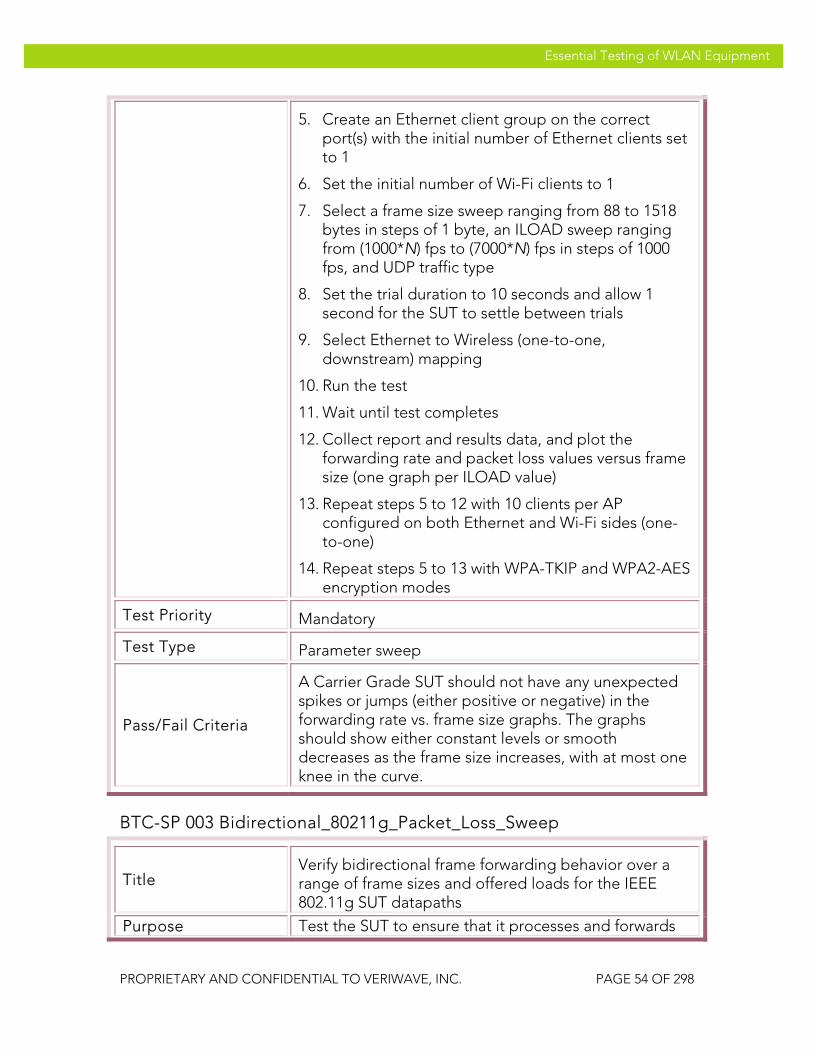
VeriWave, Inc. Essential Testing of WLAN Equipment
PROPRIETARY AND CONFIDENTIAL TO VERIWAVE, INC. PAGE 54 OF 298
Essential Testing of WLAN Equipment
5. Create an Ethernet client group on the correct port(s) with the initial number of Ethernet clients set to 1
6. Set the initial number of Wi-Fi clients to 1
7. Select a frame size sweep ranging from 88 to 1518 bytes in steps of 1 byte, an ILOAD sweep ranging from (1000*N) fps to (7000*N) fps in steps of 1000 fps, and UDP traffic type
8. Set the trial duration to 10 seconds and allow 1 second for the SUT to settle between trials
9. Select Ethernet to Wireless (one-to-one, downstream) mapping
10. Run the test
11. Wait until test completes
12. Collect report and results data, and plot the forwarding rate and packet loss values versus frame size (one graph per ILOAD value)
13. Repeat steps 5 to 12 with 10 clients per AP configured on both Ethernet and Wi-Fi sides (one-to-one)
14. Repeat steps 5 to 13 with WPA-TKIP and WPA2-AES encryption modes
Test Priority Mandatory
Test Type Parameter sweep
Pass/Fail Criteria
A Carrier Grade SUT should not have any unexpected spikes or jumps (either positive or negative) in the forwarding rate vs. frame size graphs. The graphs should show either constant levels or smooth decreases as the frame size increases, with at most one knee in the curve.
BTC-SP 003 Bidirectional_80211g_Packet_Loss_Sweep
Title Verify bidirectional frame forwarding behavior over a range of frame sizes and offered loads for the IEEE 802.11g SUT datapaths
Purpose Test the SUT to ensure that it processes and forwards

VeriWave, Inc. Essential Testing of WLAN Equipment
PROPRIETARY AND CONFIDENTIAL TO VERIWAVE, INC. PAGE 55 OF 298
Essential Testing of WLAN Equipment
concurrent Ethernet-to-wireless and wireless-to-Ethernet frames uniformly regardless of the specific frame size or the specific traffic load that is presented to it. Test traffic is injected into all of the SUT ports in both the downstream and upstream directions and a sweep is performed over all legal frame sizes and a large number of offered loads. When plotted on a graph, the results will clearly indicate any anomalies or forwarding performance issues. This test also indicates how well the SUT responds to contention over the entire range of frame sizes.
SUT Feature(s) Tested
Uniform traffic handling datapath, anomalous forwarding performance, instabilities, contention handling
Requirement(s)
• WaveApps application running on host PC • WT-90 or WT-20 chassis with Wi-Fi WaveBlade(s)
and Ethernet WaveBlade(s) • SUT set up to support UDP traffic with static IP
addressing • SUT configured with IEEE 802.11g APs
Test Setup
• Configure the SUT with open-system authentication mode
• Set Basic Rate Set on SUT to 1Mbps, 2Mbps, 5.5Mbps, 6Mbps, 11Mbps, 12Mbps, 24Mbps
• Set client PHY rate to 54 Mb/s in IEEE 802.11g-only mode
• Run test with no encryption, TKIP and AES-CCMP • Run test with all UDP frame sizes ranging from 88
bytes to 1518 bytes inclusive in 1 byte steps (1431 values)
• Run test with 1 and 10 clients per AP • Run test with intended load (ILOAD) values ranging
from 1000 to 7000 frames/second (inclusive) per AP in 2000 byte steps (4 values).
Procedure
1. Launch the WaveApps application
2. Select the Packet Loss Test under the IEEE 802.11.2 Benchmark Test Suite
3. Select the test port(s) (i.e., APs) to use for the test, and note the number of APs as N

VeriWave, Inc. Essential Testing of WLAN Equipment
PROPRIETARY AND CONFIDENTIAL TO VERIWAVE, INC. PAGE 56 OF 298
Essential Testing of WLAN Equipment
4. Select SSID and configure the client(s) to open authentication with no encryption and to use static IP address(es)
5. Create an Ethernet client group on the correct port(s) with the initial number of Ethernet clients set to 1
6. Set the initial number of Wi-Fi clients to 1
7. Select a frame size sweep ranging from 88 to 1518 bytes in steps of 1 byte, an ILOAD sweep ranging from (1000*N) fps to (7000*N) fps in steps of 1000 fps, and UDP traffic type
8. Set the trial duration to 10 seconds and allow 1 second for the SUT to settle between trials
9. Select Wireless to Ethernet bidirectional (one-to-one) mapping with the bidirectional option checked
10. Run the test
11. Wait until test completes
12. Collect report and results data, and plot the forwarding rate and packet loss values versus frame size (one graph per ILOAD value)
13. Repeat steps 5 to 12 with 10 clients per AP configured on both Ethernet and Wi-Fi sides (one-to-one), and media contention turned on for the clients
14. Repeat steps 5 to 13 with WPA-TKIP and WPA2-AES encryption modes
Test Priority Mandatory
Test Type Parameter sweep
Pass/Fail Criteria
A Carrier Grade SUT should not have any unexpected spikes or jumps (either positive or negative) in the forwarding rate vs. frame size graphs. The graphs should show either constant levels or smooth decreases as the frame size increases, with at most one knee in the curve.
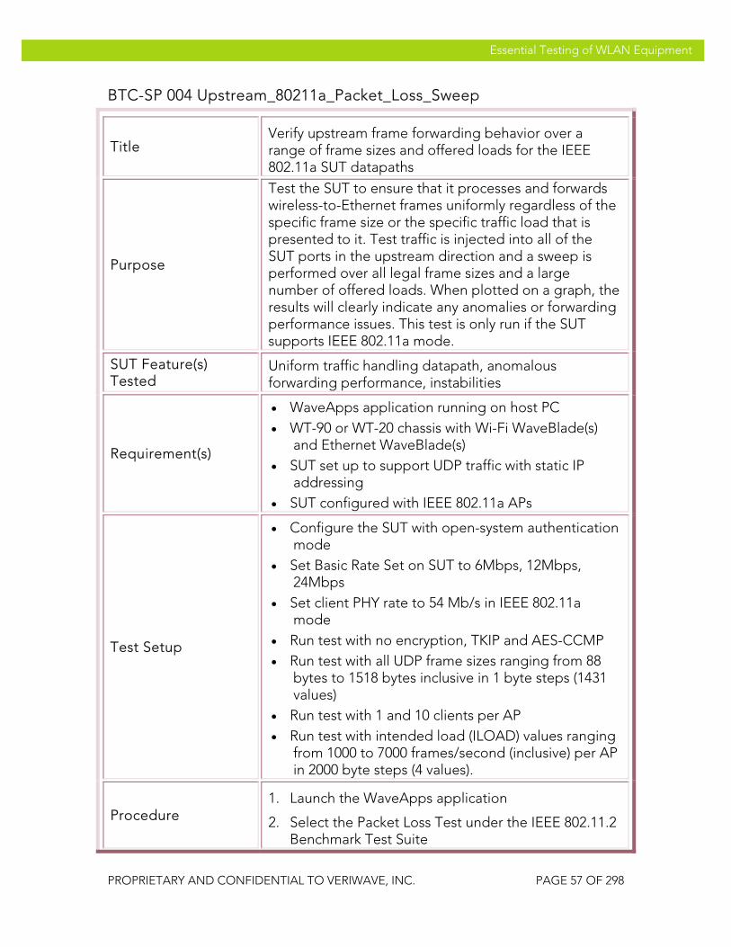
VeriWave, Inc. Essential Testing of WLAN Equipment
PROPRIETARY AND CONFIDENTIAL TO VERIWAVE, INC. PAGE 57 OF 298
Essential Testing of WLAN Equipment
BTC-SP 004 Upstream_80211a_Packet_Loss_Sweep
Title Verify upstream frame forwarding behavior over a range of frame sizes and offered loads for the IEEE 802.11a SUT datapaths
Purpose
Test the SUT to ensure that it processes and forwards wireless-to-Ethernet frames uniformly regardless of the specific frame size or the specific traffic load that is presented to it. Test traffic is injected into all of the SUT ports in the upstream direction and a sweep is performed over all legal frame sizes and a large number of offered loads. When plotted on a graph, the results will clearly indicate any anomalies or forwarding performance issues. This test is only run if the SUT supports IEEE 802.11a mode.
SUT Feature(s) Tested
Uniform traffic handling datapath, anomalous forwarding performance, instabilities
Requirement(s)
• WaveApps application running on host PC • WT-90 or WT-20 chassis with Wi-Fi WaveBlade(s)
and Ethernet WaveBlade(s) • SUT set up to support UDP traffic with static IP
addressing • SUT configured with IEEE 802.11a APs
Test Setup
• Configure the SUT with open-system authentication mode
• Set Basic Rate Set on SUT to 6Mbps, 12Mbps, 24Mbps
• Set client PHY rate to 54 Mb/s in IEEE 802.11a mode
• Run test with no encryption, TKIP and AES-CCMP • Run test with all UDP frame sizes ranging from 88
bytes to 1518 bytes inclusive in 1 byte steps (1431 values)
• Run test with 1 and 10 clients per AP • Run test with intended load (ILOAD) values ranging
from 1000 to 7000 frames/second (inclusive) per AP in 2000 byte steps (4 values).
Procedure 1. Launch the WaveApps application
2. Select the Packet Loss Test under the IEEE 802.11.2 Benchmark Test Suite
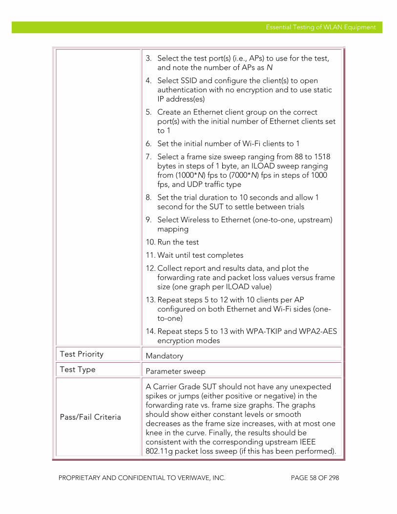
VeriWave, Inc. Essential Testing of WLAN Equipment
PROPRIETARY AND CONFIDENTIAL TO VERIWAVE, INC. PAGE 58 OF 298
Essential Testing of WLAN Equipment
3. Select the test port(s) (i.e., APs) to use for the test, and note the number of APs as N
4. Select SSID and configure the client(s) to open authentication with no encryption and to use static IP address(es)
5. Create an Ethernet client group on the correct port(s) with the initial number of Ethernet clients set to 1
6. Set the initial number of Wi-Fi clients to 1
7. Select a frame size sweep ranging from 88 to 1518 bytes in steps of 1 byte, an ILOAD sweep ranging from (1000*N) fps to (7000*N) fps in steps of 1000 fps, and UDP traffic type
8. Set the trial duration to 10 seconds and allow 1 second for the SUT to settle between trials
9. Select Wireless to Ethernet (one-to-one, upstream) mapping
10. Run the test
11. Wait until test completes
12. Collect report and results data, and plot the forwarding rate and packet loss values versus frame size (one graph per ILOAD value)
13. Repeat steps 5 to 12 with 10 clients per AP configured on both Ethernet and Wi-Fi sides (one-to-one)
14. Repeat steps 5 to 13 with WPA-TKIP and WPA2-AES encryption modes
Test Priority Mandatory
Test Type Parameter sweep
Pass/Fail Criteria
A Carrier Grade SUT should not have any unexpected spikes or jumps (either positive or negative) in the forwarding rate vs. frame size graphs. The graphs should show either constant levels or smooth decreases as the frame size increases, with at most one knee in the curve. Finally, the results should be consistent with the corresponding upstream IEEE 802.11g packet loss sweep (if this has been performed).

VeriWave, Inc. Essential Testing of WLAN Equipment
PROPRIETARY AND CONFIDENTIAL TO VERIWAVE, INC. PAGE 59 OF 298
Essential Testing of WLAN Equipment
BTC-SP 005 Downstream_80211a_Packet_Loss_Sweep
Title Verify downstream frame forwarding behavior over a range of frame sizes and offered loads for the IEEE 802.11a SUT datapaths
Purpose
Test the SUT to ensure that it processes and forwards Ethernet-to-wireless frames uniformly regardless of the specific frame size or the specific traffic load that is presented to it. Test traffic is injected into all of the SUT ports in the downstream direction and a sweep is performed over all legal frame sizes and a large number of offered loads. When plotted on a graph, the results will clearly indicate any anomalies or forwarding performance issues. This test is only run if the SUT supports IEEE 802.11a mode.
SUT Feature(s) Tested
Uniform traffic handling datapath, anomalous forwarding performance, instabilities
Requirement(s)
• WaveApps application running on host PC • WT-90 or WT-20 chassis with Wi-Fi WaveBlade(s)
and Ethernet WaveBlade(s) • SUT set up to support UDP traffic with static IP
addressing • SUT configured with IEEE 802.11a APs
Test Setup
• Configure the SUT with open-system authentication mode
• Set Basic Rate Set on SUT to 6Mbps, 12Mbps, 24Mbps
• Set client PHY rate to 54 Mb/s in IEEE 802.11a mode
• Run test with no encryption, TKIP and AES-CCMP • Run test with all UDP frame sizes ranging from 88
bytes to 1518 bytes inclusive in 1 byte steps (1431 values)
• Run test with 1 and 10 clients per AP • Run test with intended load (ILOAD) values ranging
from 1000 to 7000 frames/second (inclusive) per AP in 2000 byte steps (4 values).
Procedure 1. Launch the WaveApps application
2. Select the Packet Loss Test under the IEEE 802.11.2 Benchmark Test Suite

VeriWave, Inc. Essential Testing of WLAN Equipment
PROPRIETARY AND CONFIDENTIAL TO VERIWAVE, INC. PAGE 60 OF 298
Essential Testing of WLAN Equipment
3. Select the test port(s) (i.e., APs) to use for the test, and note the number of APs as N
4. Select SSID and configure the client(s) to open authentication with no encryption and to use static IP address(es)
5. Create an Ethernet client group on the correct port(s) with the initial number of Ethernet clients set to 1
6. Set the initial number of Wi-Fi clients to 1
7. Select a frame size sweep ranging from 88 to 1518 bytes in steps of 1 byte, an ILOAD sweep ranging from (1000*N) fps to (7000*N) fps in steps of 1000 fps, and UDP traffic type
8. Set the trial duration to 10 seconds and allow 1 second for the SUT to settle between trials
9. Select Ethernet to Wireless (one-to-one, downstream) mapping
10. Run the test
11. Wait until test completes
12. Collect report and results data, and plot the forwarding rate and packet loss values versus frame size (one graph per ILOAD value)
13. Repeat steps 5 to 12 with 10 clients per AP configured on both Ethernet and Wi-Fi sides (one-to-one)
14. Repeat steps 5 to 13 with WPA-TKIP and WPA2-AES encryption modes
Test Priority Mandatory
Test Type Parameter sweep
Pass/Fail Criteria
A Carrier Grade SUT should not have any unexpected spikes or jumps (either positive or negative) in the forwarding rate vs. frame size graphs. The graphs should show either constant levels or smooth decreases as the frame size increases, with at most one knee in the curve. Finally, the results should be consistent with the corresponding upstream IEEE 802.11g packet loss sweep (if this has been performed).

VeriWave, Inc. Essential Testing of WLAN Equipment
PROPRIETARY AND CONFIDENTIAL TO VERIWAVE, INC. PAGE 61 OF 298
Essential Testing of WLAN Equipment
BTC-SP 006 Bidirectional_80211a_Packet_Loss_Sweep
Title Verify bidirectional frame forwarding behavior over a range of frame sizes and offered loads for the IEEE 802.11a SUT datapaths
Purpose
Test the SUT to ensure that it processes and forwards concurrent Ethernet-to-wireless and wireless-to-Ethernet frames uniformly regardless of the specific frame size or the specific traffic load that is presented to it. Test traffic is injected into all of the SUT ports in both the downstream and upstream directions and a sweep is performed over all legal frame sizes and a large number of offered loads. When plotted on a graph, the results will clearly indicate any anomalies or forwarding performance issues. This test also indicates how well the SUT responds to contention over the entire range of frame sizes. This test is only run if the SUT supports IEEE 802.11a mode.
SUT Feature(s) Tested
Uniform traffic handling datapath, anomalous forwarding performance, instabilities, contention handling
Requirement(s)
• WaveApps application running on host PC • WT-90 or WT-20 chassis with Wi-Fi WaveBlade(s)
and Ethernet WaveBlade(s) • SUT set up to support UDP traffic with static IP
addressing • SUT configured with IEEE 802.11a APs
Test Setup
• Configure the SUT with open-system authentication mode
• Set Basic Rate Set on SUT to 6Mbps, 12Mbps, 24Mbps
• Set client PHY rate to 54 Mb/s in IEEE 802.11a mode
• Run test with no encryption, TKIP and AES-CCMP • Run test with all UDP frame sizes ranging from 88
bytes to 1518 bytes inclusive in 1 byte steps (1431 values)
• Run test with 1 and 10 clients per AP • Run test with intended load (ILOAD) values ranging
from 1000 to 7000 frames/second (inclusive) per AP in 2000 byte steps (4 values).

VeriWave, Inc. Essential Testing of WLAN Equipment
PROPRIETARY AND CONFIDENTIAL TO VERIWAVE, INC. PAGE 62 OF 298
Essential Testing of WLAN Equipment
Procedure
1. Launch the WaveApps application
2. Select the Packet Loss Test under the IEEE 802.11.2 Benchmark Test Suite
3. Select the test port(s) (i.e., APs) to use for the test, and note the number of APs as N
4. Select SSID and configure the client(s) to open authentication with no encryption and to use static IP address(es)
5. Create an Ethernet client group on the correct port(s) with the initial number of Ethernet clients set to 1
6. Set the initial number of Wi-Fi clients to 1
7. Select a frame size sweep ranging from 88 to 1518 bytes in steps of 1 byte, an ILOAD sweep ranging from (1000*N) fps to (7000*N) fps in steps of 1000 fps, and UDP traffic type
8. Set the trial duration to 10 seconds and allow 1 second for the SUT to settle between trials
9. Select Wireless to Ethernet bidirectional (one-to-one) mapping with the bidirectional option checked
10. Run the test
11. Wait until test completes
12. Collect report and results data, and plot the forwarding rate and packet loss values versus frame size (one graph per ILOAD value)
13. Repeat steps 5 to 12 with 10 clients per AP configured on both Ethernet and Wi-Fi sides (one-to-one), and media contention turned on for the clients
14. Repeat steps 5 to 13 with WPA-TKIP and WPA2-AES encryption modes
Test Priority Mandatory
Test Type Parameter sweep
Pass/Fail Criteria A Carrier Grade SUT should not have any unexpected spikes or jumps (either positive or negative) in the forwarding rate vs. frame size graphs. The graphs

VeriWave, Inc. Essential Testing of WLAN Equipment
PROPRIETARY AND CONFIDENTIAL TO VERIWAVE, INC. PAGE 63 OF 298
Essential Testing of WLAN Equipment
should show either constant levels or smooth decreases as the frame size increases, with at most one knee in the curve. Finally, the results should be consistent with the corresponding upstream IEEE 802.11g packet loss sweep (if this has been performed).
Power Save
Mobile wireless clients implement different levels of power save depending on the application and battery life requirements. Handsets use aggressive sleep modes to conserve battery life, while a laptop may use a less aggressive power save level to deliver higher throughput performance. Service provider networks are used in highly mobile, battery-powered environments, and thus must efficiently support power save clients.
To support power save clients, the SUT must buffer traffic intended for sleeping stations, and deliver it as quickly as possible when the stations wake up and request the data. Failure to implement these functions results in an inability to support battery-powered WLAN clients.
These tests verify the functionality implemented in the SUT to support clients in various sleep modes, ranging from fully awake (CAM, or Continuous Awake Mode) to deep sleep. Different security modes are also tested.
PTC-SP 001 Power_Save_Baseline_CAM_Test
Title Verify support of Continuous Awake Mode (CAM) functionality, to serve as a baseline
Purpose
Test the SUT for support of different numbers of WLAN clients with power-save mode turned off. Downstream test traffic will be sent to each associated client in order to verify that the SUT does not buffer traffic to stations not in power-save mode.
SUT Feature(s) Tested
CAM mode
Requirement(s)
• Wavemanager application running on host PC • WT-90 or WT-20 chassis with Wi-Fi WaveBlade(s)
and Ethernet WaveBlade(s) • SUT set up to support UDP traffic • Static IP addressing configured in the SUT
Test Setup • Connect the Wi-Fi WaveBlade(s) to the SUT via RF
cables • Configure static IP subnets in the SUT and related
VeriWave, Inc. Essential Testing of WLAN Equipment
PROPRIETARY AND CONFIDENTIAL TO VERIWAVE, INC. PAGE 64 OF 298
Essential Testing of WLAN Equipment
network • Configure the SUT with open-system authentication
mode • Set Basic Rate Set on SUT AP(s) to 1Mbps, 2Mbps,
5.5Mbps, 6Mbps, 11Mbps, 12Mbps and 24Mbps (IEEE 802.11g APs, if present) or 6Mbps, 12Mbps and 24Mbps (IEEE 802.11a APs, if present)
• Set client flow PHY rate to 54 Mb/s and management (i.e., connection) PHY rate to 6 Mb/s
• Set the aggregate offered test traffic load per AP to 100 frames/second, downstream
• Run test with UDP frame sizes: 88, 512, 1518 bytes • Run test with 1, 10, and 100 clients per SUT AP • Run test with Open, WPA-PSK, and WPA2-PSK
security modes
Procedure
1. Launch the WaveManager application
2. Select the test port(s) (i.e., AP(s) in SUT) and channel(s) to use for the test
3. Configure 1 Wi-Fi client profile with open security mode (no encryption) and static IP addressing
4. Set the Wi-Fi client profile to Power Save Mode OFF
5. Create an Ethernet client profile with static IP addressing
6. Create a traffic profile to send 1000 frames of fixed length at 100 frames/second
7. Set the initial frame size in the traffic profile to 88 bytes
8. Set the initial number of Wi-Fi clients per AP to 1
9. Create a flow from Ethernet to Wireless using the above profiles, with 1:N mapping and the appropriate ports
10. Run the test by starting traffic
11. Wait until the test completes and the counters have settled, then stop the test
12. Save the flow TX/RX packet transfer and latency results and inspect the data

VeriWave, Inc. Essential Testing of WLAN Equipment
PROPRIETARY AND CONFIDENTIAL TO VERIWAVE, INC. PAGE 65 OF 298
Essential Testing of WLAN Equipment
13. Repeat steps 6 to 12 with 10 clients per AP, setting the traffic profile to transmit 100 frames at 10 frames/second
14. Repeat steps 6 to 12 with 100 clients per AP, setting the traffic profile to transmit 10 frames at 1 frames/second
15. Repeat steps 6 to 14 with frame sizes of 88, 512, 1518 bytes
16. Repeat steps 3 to 15 with WPA-PSK and WPA2-PSK security modes set in the Wi-Fi client profile
Test Priority High
Test Type Power Save
Pass/Fail Criteria
The Wi-Fi client(s) should successfully associate with the SUT and receive traffic from the Ethernet client with zero packet loss under all test conditions, and with latency under 50 milliseconds for all test conditions.
PTC-SP 002 Power-Save_Legacy_PS_Poll
Title Verify support of client power-save functionality using the legacy Power Save Poll (PS-Poll) mechanism
Purpose
Test the SUT for support of different numbers of WLAN clients using the PS-Poll based power-save handshake mode. Downstream traffic will be sent to each associated client in order to verify that the SUT correctly does the following: buffers traffic when the stations are in PS-mode, indicates the existence of buffered traffic using its beacons, and delivers the buffered frames properly when the clients wake up at different listen intervals. The test clients will request the frames via PS-Poll.
SUT Feature(s) Tested
Power save buffering and delivery, PS-Poll handling, announcement via TIM bitmaps in beacons
Requirement(s)
• Wavemanager application running on host PC • WT-90 or WT-20 chassis with Wi-Fi WaveBlade(s)
and Ethernet WaveBlade(s) • SUT set up to support UDP traffic • Static IP addressing configured in the SUT
VeriWave, Inc. Essential Testing of WLAN Equipment
PROPRIETARY AND CONFIDENTIAL TO VERIWAVE, INC. PAGE 66 OF 298
Essential Testing of WLAN Equipment
Test Setup
• Connect the Wi-Fi WaveBlade(s) to the SUT via RF cables
• Configure static IP subnets in the SUT and related network
• Configure the SUT with open-system authentication mode
• Set Basic Rate Set on SUT AP(s) to 1Mbps, 2Mbps, 5.5Mbps, 6Mbps, 11Mbps, 12Mbps and 24Mbps (IEEE 802.11g APs, if present) or 6Mbps, 12Mbps and 24Mbps (IEEE 802.11a APs, if present)
• Set client flow PHY rate to 54 Mb/s and management (i.e., connection) PHY rate to 6 Mb/s
• Set the aggregate offered test traffic load per AP to 100 frames/second, downstream
• Run test with UDP frame sizes: 88, 512, 1518 bytes • Run test with 1, 10, and 100 clients per SUT AP • Run test with listen intervals of 1, 5 and 10 beacon
periods • Run test with Open, WPA-PSK, and WPA2-PSK
security modes
Procedure
1. Launch the WaveManager application
2. Select the test port(s) (i.e., AP(s) in SUT) and channel(s) to use for the test
3. Configure 1 Wi-Fi client profile with open security mode (no encryption) and static IP addressing
4. Set the Wi-Fi client profile to Power Save Mode ON and a listen interval of 1 beacon period
5. Create an Ethernet client profile with static IP addressing
6. Create a traffic profile to send 1000 frames of fixed length at 100 frames/second
7. Set the initial frame size in the traffic profile to 88 bytes
8. Set the initial number of Wi-Fi clients per AP to 1
9. Create one flow from the Ethernet client to each wireless client using the above profiles, with 1:N mapping and the appropriate ports
10. Run the test by starting traffic, then stopping after

VeriWave, Inc. Essential Testing of WLAN Equipment
PROPRIETARY AND CONFIDENTIAL TO VERIWAVE, INC. PAGE 67 OF 298
Essential Testing of WLAN Equipment
approximately 30 seconds
11. Wait until the test completes and the counters have settled, then stop the test
12. Save the flow TX/RX packet transfer and latency results and inspect the data
13. Repeat steps 4 to 12 with listen intervals of 5 and 10 beacon periods
14. Repeat steps 4 to 13 with 10 clients per AP, setting the traffic profile to transmit 100 frames at 10 frames/second
15. Repeat steps 4 to 13 with 100 clients per AP, setting the traffic profile to transmit 10 frames at 1 frame/second
16. Repeat steps 4 to 15 with frame sizes of 88, 512, 1518 bytes
17. Repeat steps 4 to 15 with WPA-PSK and WPA2-PSK security modes set in the Wi-Fi client profile
Test Priority High
Test Type Power Save
Pass/Fail Criteria
The Wi-Fi client(s) should successfully associate with the SUT and receive traffic from the Ethernet client with zero packet loss under all test conditions. The average latency should not exceed 50% of the configured listen interval + 1 beacon period, and the maximum latency should not exceed the configured listen interval + 1 beacon period. (Note: the nominal beacon period is usually 102.4 msec.)
PTC-SP 003 Power-Save_Legacy_Null_Frame
Title Verify support of client power-save functionality using the legacy Null Data Frame power save mechanism
Purpose
Test the SUT for support of different numbers of WLAN clients using the Null Data Frame based power-save handshake mode. Downstream traffic will be sent to each associated client in order to verify that the SUT correctly does the following: buffers traffic when the stations are in PS-mode, indicates the existence of buffered traffic using its beacons, and delivers the

VeriWave, Inc. Essential Testing of WLAN Equipment
PROPRIETARY AND CONFIDENTIAL TO VERIWAVE, INC. PAGE 68 OF 298
Essential Testing of WLAN Equipment
buffered frames properly when the clients wake up at different listen intervals. The test clients will request the frames by transmitting a Null Data Frame with the PS bit cleared.
SUT Feature(s) Tested
Power save buffering and delivery, Null Data Frame handling, announcement via TIM bitmaps in beacons
Requirement(s)
• Wavemanager application running on host PC • WT-90 or WT-20 chassis with Wi-Fi WaveBlade(s)
and Ethernet WaveBlade(s) • SUT set up to support UDP traffic • Static IP addressing configured in the SUT
Test Setup
• Connect the Wi-Fi WaveBlade to the SUT via RF cables
• Configure static IP subnets in the SUT and related network
• Configure the SUT with open-system authentication mode
• Set Basic Rate Set on SUT AP(s) to 1Mbps, 2Mbps, 5.5Mbps, 6Mbps, 11Mbps, 12Mbps and 24Mbps (IEEE 802.11g APs, if present) or 6Mbps, 12Mbps and 24Mbps (IEEE 802.11a APs, if present)
• Set client flow PHY rate to 54 Mb/s and management (i.e., connection) PHY rate to 6 Mb/s
• Set the aggregate offered test traffic load per AP to 100 frames/second, downstream
• Run test with UDP frame sizes: 88, 512, 1518 bytes • Run test with 1, 10, and 100 clients per SUT AP • Run test with listen intervals of 1, 5 and 10 beacon
periods • Run test with awake times of 50 and 100
milliseconds • Run test with Open, WPA-PSK, and WPA2-PSK
security modes
Procedure TBD
Test Priority Medium
Test Type Power Save
Pass/Fail Criteria TBD

VeriWave, Inc. Essential Testing of WLAN Equipment
PROPRIETARY AND CONFIDENTIAL TO VERIWAVE, INC. PAGE 69 OF 298
Essential Testing of WLAN Equipment
PTC-SP 004 Power-Save_APSD
Title Verify support of client power-save functionality using WMM Power Save (U-APSD)
Purpose
Test the SUT for support of different numbers of WLAN clients using WMM (802.11e) U-APSD based power-save handshake mode. Downstream traffic will be sent to each associated client in order to verify that the SUT correctly does the following: buffers traffic when the stations are in PS-mode, indicates the existence of buffered traffic using its beacons, and delivers the buffered frames properly when the clients wake up at different listen intervals. The test clients will request the frames via U-APSD trigger frames.
SUT Feature(s) Tested
Power save buffering and delivery, U-APSD protocol support, trigger frame handling, announcement via TIM bitmaps in beacons, U-APSD SP length support
Requirement(s)
• U-APSD test script running on host PC • WT-90 or WT-20 chassis with Wi-Fi WaveBlade(s)
and Ethernet WaveBlade(s) • SUT set up to support UDP traffic • Static IP addressing configured in the SUT
Test Setup
• Connect the Wi-Fi WaveBlade to the SUT via RF cables
• Configure static IP subnets in the SUT and related network
• Configure the SUT with open-system authentication mode
• Set Basic Rate Set on SUT AP(s) to 1Mbps, 2Mbps, 5.5Mbps, 6Mbps, 11Mbps, 12Mbps and 24Mbps (IEEE 802.11g APs, if present) or 6Mbps, 12Mbps and 24Mbps (IEEE 802.11a APs, if present)
• Set client flow PHY rate to 54 Mb/s and management (i.e., connection) PHY rate to 6 Mb/s
• Set the aggregate offered test traffic load per AP to 100 frames/second, downstream
• Run test with UDP frame sizes: 88, 512, 1518 bytes • Run test with 1, 10, and 100 clients per SUT AP • Run test with listen intervals of 1, 5 and 10 beacon
periods
VeriWave, Inc. Essential Testing of WLAN Equipment
PROPRIETARY AND CONFIDENTIAL TO VERIWAVE, INC. PAGE 70 OF 298
Essential Testing of WLAN Equipment
• Run test with service periods (SP) of 0, 2, 4 and 6 frames
• Run test with Open, WPA-PSK, and WPA2-PSK security modes
• Run test with ACs of AC_BE, AC_BK, AC_VI and AC_VO
Procedure
1. Configure the U-APSD script parameters according to the trial being run, as per steps 2 through 8
2. Select the test port(s) (i.e., AP(s) in SUT) and channel(s) to use for the test
3. Configure the traffic parameters to send 1000 frames of fixed length at 100 frames/second with 88, 512 and 1512 byte frame sizes on successive iterations
4. Configure 1 Ethernet source client with static IP addressing
5. Configure 1 Wi-Fi client per AP with open security (no encryption), static IP addressing, and U-APSD PS mode
6. Set the initial AC to AC_BE
7. Set the initial listen interval to 1 beacon period
8. Set the initial service period (SP) to 0 frames
9. Run the test by executing the script
10. Wait until the test completes and the results have been written
11. Save the flow TX/RX packet transfer and latency information and inspect the data
12. Repeat steps 9 to 11 with service periods of 2, 4, and 6 frames
13. Repeat steps 9 to 12 with listen intervals of 5 and 10 beacon periods
14. Repeat steps 7 to 13 with AC set to AC_BK, AC_VI & AC_VO
15. Repeat steps 6 to 14 with 10 clients per AP, setting the traffic parameters for 100 frames for each client at 10 frames/second
16. Repeat steps 6 to 14 with 100 clients per AP, setting

VeriWave, Inc. Essential Testing of WLAN Equipment
PROPRIETARY AND CONFIDENTIAL TO VERIWAVE, INC. PAGE 71 OF 298
Essential Testing of WLAN Equipment
the traffic parameters for 10 frames for each client at 1 frames/second
17. Repeat steps 6 to 16 with WPA-PSK and WPA2-PSK security modes for the Wi-Fi client(s)
Test Priority Medium
Test Type Power Save
Pass/Fail Criteria
The Wi-Fi client(s) should successfully associate with the SUT and receive traffic from the Ethernet client with zero packet loss under all test conditions. The average latency should not exceed 50% of the configured listen interval + 1 beacon period, and the maximum latency should not exceed the configured listen interval + 1 beacon period. (Note: the nominal beacon period is usually 102.4 msec.) For non-zero service periods, the average latency should decrease as the service period increases.
PTC-SP 005 Power-Save_Mixed_3
Title Verify support of client power-save functionality using a mixture of non-power-save (CAM), legacy PS-Poll and U-APSD stations
Purpose
Test the SUT for support of mixed networks of WLAN clients using CAM (non-power-save) mode, legacy PS-Poll PS-mode, and U-APSD PS-mode. Downstream traffic will be sent to each associated client in order to verify that the SUT correctly does the following: does not buffer traffic to CAM stations, buffers traffic to the stations in PS-mode whether legacy PS-Poll or U-APSD, indicates the existence of buffered traffic using its beacons, and delivers the buffered frames properly when the sleeping clients wake up at different listen intervals.
SUT Feature(s) Tested
Power save buffering and delivery, per-client power save state maintenance, per-client distinction between U-APSD and legacy PS-mode states, concurrent PS-Poll and trigger frame handling, selective announcement via TIM bitmaps in beacons
Requirement(s) • U-APSD test script running on host PC

VeriWave, Inc. Essential Testing of WLAN Equipment
PROPRIETARY AND CONFIDENTIAL TO VERIWAVE, INC. PAGE 72 OF 298
Essential Testing of WLAN Equipment
• WT-90 or WT-20 chassis with Wi-Fi WaveBlade(s) and Ethernet WaveBlade(s)
• SUT set up to support UDP traffic • Static IP addressing configured in the SUT
Test Setup
• Connect the Wi-Fi WaveBlade to the SUT via RF cables
• Configure static IP subnets in the SUT and related network
• Configure the SUT with open-system authentication mode
• Set Basic Rate Set on SUT AP(s) to 1Mbps, 2Mbps, 5.5Mbps, 6Mbps, 11Mbps, 12Mbps and 24Mbps (IEEE 802.11g APs, if present) or 6Mbps, 12Mbps and 24Mbps (IEEE 802.11a APs, if present)
• Set client flow PHY rate to 54 Mb/s and management (i.e., connection) PHY rate to 6 Mb/s
• Set the aggregate offered test traffic load per AP to 200 frames/second, downstream
• Run test with UDP frame sizes: 88, 512, 1518 bytes • Run test with 1, 3, and 33 legacy PS-Poll power-save
clients per AP, 1, 3 and 33 U-APSD clients per AP, and 1, 3 and 33 CAM clients per AP
• Run test with listen intervals of 1, 5 and 10 beacon periods for both U-APSD and PS-Poll clients
• Run test with service periods (SP) of 0, 2, 4 and 6 frames for U-APSD clients
• Run test with Open, WPA-PSK, and WPA2-PSK security modes for both PS-mode and CAM clients
• Run test with ACs of AC_BE, AC_BK, AC_VI and AC_VO
Procedure
1. Configure the U-APSD script parameters according to the trial being run, as per steps 2 through 10
2. Select the test port(s) (i.e., AP(s) in SUT) and channel(s) to use for the test
3. Configure the traffic parameters to send 1000 frames of fixed length at 100 frames/second per flow, with 88, 512 and 1512 byte frame sizes on successive iterations
4. Configure 1 Ethernet source client with static IP

VeriWave, Inc. Essential Testing of WLAN Equipment
PROPRIETARY AND CONFIDENTIAL TO VERIWAVE, INC. PAGE 73 OF 298
Essential Testing of WLAN Equipment
addressing
5. Configure 1 Wi-Fi client per AP with open security (no encryption), static IP addressing, and CAM mode
6. Configure 1 more Wi-Fi client per AP with open security (no encryption), static IP addressing, and legacy PS-Poll PS mode
7. Configure 1 more Wi-Fi client per AP with open security (no encryption), static IP addressing, and U-APSD PS mode
8. Set the initial AC for the CAM and PS-mode Wi-Fi clients to AC_BE
9. Set the initial listen interval for the PS-mode clients to 1 beacon period
10. Set the initial service period (SP) to 0 frames
11. Run the test by executing the script
12. Wait until the test completes and the results have been written
13. Save the flow TX/RX frame counts and latency information and inspect the data
14. Repeat steps 11 to 13 with service periods of 2, 4, and 6 frames for the U-APSD clients
15. Repeat steps 10 to 14 with listen intervals of 5 and 10 beacon periods for the PS-mode clients (both legacy and U-APSD)
16. Repeat steps 9 to 15 with the AC for all the Wi-Fi clients set to AC_BK, AC_VI and finally AC_VO
17. Repeat steps 5 to 16 with 3 CAM, 3 legacy PS-Poll, and 3 U-APSD clients per AP, setting the traffic parameters for each flow to 100 frames for each client at 10 frames/second
18. Repeat steps 5 to 16 with 33 CAM, 33 legacy PS-Poll, and 33 U-APSD clients per AP, setting the traffic parameters for 10 frames for each client at 1 frames/second
19. Repeat steps 5 to 18 with WPA-PSK and WPA2-PSK security modes for all the Wi-Fi clients
Test Priority Medium

VeriWave, Inc. Essential Testing of WLAN Equipment
PROPRIETARY AND CONFIDENTIAL TO VERIWAVE, INC. PAGE 74 OF 298
Essential Testing of WLAN Equipment
Test Type Power Save
Pass/Fail Criteria
All of the Wi-Fi clients should successfully associate with the SUT and receive traffic from the Ethernet client with zero packet loss under all test conditions. The average latency for the CAM client traffic flows should not exceed 10 milliseconds. The average latency for the PS-mode clients should be substantially larger than the average latency of the CAM clients (i.e., at least 100% larger, and around 50% of the listen interval).
PTC-SP 006 Power-Save_Mixed_5
Title
Verify support of client power-save functionality using a mixture of legacy PS-Poll mode for the Best Effort Access Category (AC_BE) and U-APSD for Voice Access Category (AC_VO)
Purpose
Test the SUT for support of mixed networks of WLAN clients using legacy PS-Poll mode and U-APSD power-save handshake mode, where clients in different PS-modes use different WMM ACs. Downstream traffic will be sent to each associated client in order to verify that the SUT correctly does the following: buffers traffic to the stations in PS-mode, indicates the existence of buffered traffic using its beacons, and delivers the buffered frames properly using the different ACs and delivery handshakes when the sleeping clients wake up at different listen intervals.
SUT Feature(s) Tested
Power save buffering and delivery, per-client U-APSD and legacy PS-mode state maintenance, per-AC PS-mode state maintenance and triggering, trigger frame handling, PS-Poll frame handling, selective announcement via TIM bitmaps in beacons
Requirement(s)
• U-APSD test script running on host PC • WT-90 or WT-20 chassis with Wi-Fi WaveBlade(s)
and Ethernet WaveBlade(s) • SUT set up to support UDP traffic • Static IP addressing configured in the SUT
Test Setup • Connect the Wi-Fi WaveBlade to the SUT via RF
cables • Configure static IP subnets in the SUT and related
VeriWave, Inc. Essential Testing of WLAN Equipment
PROPRIETARY AND CONFIDENTIAL TO VERIWAVE, INC. PAGE 75 OF 298
Essential Testing of WLAN Equipment
network • Configure the SUT with open-system authentication
mode • Set Basic Rate Set on SUT AP(s) to 1Mbps, 2Mbps,
5.5Mbps, 6Mbps, 11Mbps, 12Mbps and 24Mbps (IEEE 802.11g APs, if present) or 6Mbps, 12Mbps and 24Mbps (IEEE 802.11a APs, if present)
• Set client flow PHY rate to 54 Mb/s and management (i.e., connection) PHY rate to 6 Mb/s
• Set the aggregate offered test traffic load per AP to 200 frames/second, downstream
• Set the AC for legacy PS-Poll clients to AC_BE and for U-APSD clients to AC_VO
• Run test with UDP frame sizes: 88, 512, 1518 bytes • Run test with 1, 5, and 50 U-APSD clients per AP
and 1, 5 and 50 PS-Poll clients per AP • Run test with listen intervals of 1, 5 and 10 beacon
periods • Run test with service periods (SP) of 0, 2, 4 and 6
frames for U-APSD clients • Run test with Open, WPA-PSK, and WPA2-PSK
security modes for both types of clients
Procedure
1. Configure the U-APSD script parameters according to the trial being run, as per steps 2 through 9
2. Select the test port(s) (i.e., AP(s) in SUT) and channel(s) to use for the test
3. Configure the traffic parameters to send 1000 frames of fixed length at 100 frames/second per flow, with 88, 512 and 1512 byte frame sizes on successive iterations
4. Configure 1 Ethernet source client with static IP addressing
5. Configure 1 Wi-Fi client per AP with open security (no encryption), static IP addressing, legacy PS-Poll PS-mode, and AC_BE
6. Configure 1 more Wi-Fi client per AP with open security (no encryption), static IP addressing, and U-APSD PS-mode, and AC_VO
7. Set the initial listen interval to 1 beacon period

VeriWave, Inc. Essential Testing of WLAN Equipment
PROPRIETARY AND CONFIDENTIAL TO VERIWAVE, INC. PAGE 76 OF 298
Essential Testing of WLAN Equipment
8. Set the initial service period (SP) to 0 frames for U-APSD
9. Run the test by executing the script
10. Wait until the test completes and the results have been written
11. Save the flow TX/RX frame counts and latency information and inspect the data
12. Repeat steps 9 to 11 with service periods of 2, 4, and 6 frames for U-APSD clients
13. Repeat steps 8 to 12 with listen intervals of 5 and 10 beacon periods
14. Repeat steps 5 to 13 with 5 PS-Poll and 5 U-APSD clients per AP, setting the traffic parameters for each flow to 100 frames for each client at 10 frames/second
15. Repeat steps 5 to 13 with 50 PS-Poll and 50 U-APSD clients per AP, setting the traffic parameters for 10 frames for each client at 1 frames/second
16. Repeat steps 5 to 15with WPA-PSK and WPA2-PSK security modes for all the Wi-Fi clients
Test Priority Medium
Test Type Power Save
Pass/Fail Criteria
All of the Wi-Fi clients should successfully associate with the SUT and receive traffic from the Ethernet client with zero packet loss under all test conditions. The average latency for all of the Wi-Fi clients should be close to each other (i.e., in the range of +/- 10% of the listen interval).
PTC-SP 007 Power-Save_Transition_2
Title Verify support of client power-save functionality with clients transitioning between CAM and U-APSD power save mode
Purpose Test the SUT for support of WLAN clients that are using both CAM and U-APSD power-save handshake mode, where the clients transition at intervals between the

VeriWave, Inc. Essential Testing of WLAN Equipment
PROPRIETARY AND CONFIDENTIAL TO VERIWAVE, INC. PAGE 77 OF 298
Essential Testing of WLAN Equipment
two modes. Downstream traffic will be sent to each associated client in order to verify that the SUT correctly does the following: buffers traffic to the stations in PS-mode, indicates the existence of buffered traffic using its beacons, and delivers the buffered frames properly when the sleeping clients wake up at different listen intervals. Sleeping test clients will request their frames via U-APSD trigger frames.
SUT Feature(s) Tested
Power save buffering and delivery, U-APSD trigger frame handling, announcement via TIM bitmaps in beacons, state transition between CAM mode and U-APSD mode
Requirement(s)
• VeriWave PS-transition test script running on host PC
• WT-90 or WT-20 chassis with Wi-Fi WaveBlade(s) and Ethernet WaveBlade(s)
• SUT set up to support UDP traffic • Static IP addressing configured in the SUT
Test Setup
• Connect the Wi-Fi WaveBlade(s) to the SUT via RF cables
• Configure static IP subnets in the SUT and related network
• Configure the SUT with open-system authentication mode
• Set Basic Rate Set on SUT AP(s) to 1Mbps, 2Mbps, 5.5Mbps, 6Mbps, 11Mbps, 12Mbps and 24Mbps (IEEE 802.11g APs, if present) or 6Mbps, 12Mbps and 24Mbps (IEEE 802.11a APs, if present)
• Set client flow PHY rate to 54 Mb/s and management (i.e., connection) PHY rate to 6 Mb/s
• Set the aggregate offered test traffic load per AP to 100 frames/second, downstream
• Set service period (SP) to 0 frames • Run test with UDP frame sizes: 88, 512, 1518 bytes • Run test with 1, 10, and 100 clients per AP • Run test with listen intervals of 1, 5 and 10 beacon
periods • Run test with Open, WPA-PSK, and WPA2-PSK
security

VeriWave, Inc. Essential Testing of WLAN Equipment
PROPRIETARY AND CONFIDENTIAL TO VERIWAVE, INC. PAGE 78 OF 298
Essential Testing of WLAN Equipment
• Run test with ACs of AC_BE, AC_BK, AC_VI and AC_VO
Procedure
1. Configure the PS-transition script parameters according to the trial being run, as per steps 2 through 9
2. Select the test port(s) (i.e., AP(s) in SUT) and channel(s) to use for the test
3. Configure the traffic parameters to send 1000 frames of fixed length at 100 frames/second per flow, with 88, 512 and 1512 byte frame sizes on successive iterations
4. Configure the PS-mode transition interval to 10 seconds
5. Configure 1 Ethernet source client with static IP addressing
6. Configure the Wi-Fi clients with static IP addressing, and using U-APSD power-save mode with a service period (SP) of 0
7. Set the initial security mode for the Wi-Fi clients to Open (no security)
8. Set the initial number of Wi-Fi clients to 1 per AP
9. Set the initial AC for the Wi-Fi clients to AC_BE
10. Set the initial listen interval to 1 beacon period
11. Run the test by executing the script
12. Wait until the test completes and the results have been written
13. Save the flow TX/RX frame counts and latency information and inspect the data
14. Repeat steps 11 to 13 with listen intervals of 5 and 10 beacon periods for the PS-mode clients
15. Repeat steps 10 to 14 with the AC for the Wi-Fi clients set to AC_BK, AC_VI & AC_VO
16. Repeat steps 9 to 15 with 10 Wi-Fi clients per AP, setting the traffic parameters to 100 frames per client at 10 frames/second
17. Repeat steps 9 to 15 with 100 Wi-Fi clients per AP, setting the traffic parameters to 10 frames per client

VeriWave, Inc. Essential Testing of WLAN Equipment
PROPRIETARY AND CONFIDENTIAL TO VERIWAVE, INC. PAGE 79 OF 298
Essential Testing of WLAN Equipment
at 1 frame/second
18. Repeat steps 8 to 17 with WPA-PSK and WPA2-PSK security modes for all the Wi-Fi clients
Test Priority Medium
Test Type Power Save
Pass/Fail Criteria
All of the Wi-Fi clients should successfully associate with the SUT and receive traffic from the Ethernet client with zero packet loss under all test conditions. No client should be disconnected when the PS-mode transition occurs. The average latency for all of the Wi-Fi clients should be close to each other (i.e., in the range of +/- 10% of the listen interval) and should not exceed 50% of the configured listen interval + 1 beacon period.
QoS
Wireless clients need different levels of quality of service (QoS) to be provided to support different application-layer traffic types, depending on specific application requirements. For example, VoIP over WLAN (VoWLAN) traffic must be carried with low latency and jitter in order to deliver high quality voice calls. The SUT’s ability to distinguish, prioritize and efficiently transport traffic types with different QoS requirements is critical, if a good user experience is to be offered to the servicer provider’s customers. Further, the SUT must support call admission control (CAC) in order to protect the service provider network from unsustainable levels of client loads, as no QoS mechanism is capable of dealing with an overload of high-priority traffic.
The following tests verify the WMM/802.11e QoS functionality of the SUT and determine if the SUT is capable of supporting modern multimedia traffic mixes with the different QoS levels demanded by the different clients and flows. They verify basic connectivity, fairness, coexistence, and call admission control (CAC). The CAC tests present the SUT with a known excessive number of clients and verify that the SUT will refuse admission beyond a certain level.
The tests are run with combinations of various network parameters, including security settings and QoS profiles. In all cases, AC_BE refers to the WMM priority classification for Best Effort traffic; AC_BK refers to the same, for Background traffic; AC_VI refers to Video traffic; and finally AC_VO refers to Voice traffic. The corresponding 802.1D user_priority (as well as the 802.11e TID) values are 0, 1, 4, and 6 respectively.

VeriWave, Inc. Essential Testing of WLAN Equipment
PROPRIETARY AND CONFIDENTIAL TO VERIWAVE, INC. PAGE 80 OF 298
Essential Testing of WLAN Equipment
QTC-SP 001 Basic_WMM_Association
Title Verify basic support for WMM clients
Purpose
Test the SUT’s capability to accept connections by WMM-enabled clients. Bidirectional traffic is sent to and from the client(s) to verify that the connection is successful. This test also serves as a baseline for the remainder of the QoS functionality test cases.
SUT Feature(s) Tested
QoS, WMM
Requirement(s)
• Wavemanager application running on host PC • WT-90 or WT-20 chassis with Wi-Fi WaveBlade(s)
and Ethernet WaveBlade(s) • SUT set up to support UDP traffic and
WMM/802.11e QoS • Static IP addressing configured in the SUT
Test Setup
• Connect the Wi-Fi WaveBlade(s) to the SUT via RF cables
• Configure static IP subnets in the SUT and related network
• Configure the SUT with open-system authentication mode
• Configure the SUT to map four 802.1D priority classes (0, 1, 4, 6) to four 802.11e ACs (AC_BE, AC_BK, AC_VI, and AC_VO respectively)
• Set Basic Rate Set on SUT AP(s) to 1Mbps, 2Mbps, 5.5Mbps, 6Mbps, 11Mbps, 12Mbps and 24Mbps (IEEE 802.11g APs, if present) or 6Mbps, 12Mbps and 24Mbps (IEEE 802.11a APs, if present)
• Set client flow PHY rate to 54 Mb/s and management (i.e., connection) PHY rate to 6 Mb/s
• Set the aggregate offered test traffic load per AP to 1000 frames/second
• Set the QoS configuration to adopt AC parameters from the AP(s)
• Run test with UDP frame sizes: 88, 512, 1518 bytes • Run test with 1, 10, and 100 clients per SUT AP • Run test with flow QoS priority values of 0 (AC_BE),
1 (AC_BK), 4 (AC_VI), and 6 (AC_VO) • Run test with Open, WPA-PSK, and WPA2-PSK
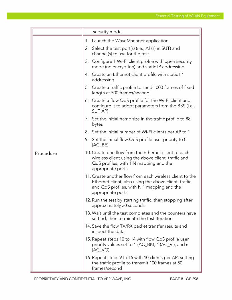
VeriWave, Inc. Essential Testing of WLAN Equipment
PROPRIETARY AND CONFIDENTIAL TO VERIWAVE, INC. PAGE 81 OF 298
Essential Testing of WLAN Equipment
security modes
Procedure
1. Launch the WaveManager application
2. Select the test port(s) (i.e., AP(s) in SUT) and channel(s) to use for the test
3. Configure 1 Wi-Fi client profile with open security mode (no encryption) and static IP addressing
4. Create an Ethernet client profile with static IP addressing
5. Create a traffic profile to send 1000 frames of fixed length at 500 frames/second
6. Create a flow QoS profile for the Wi-Fi client and configure it to adopt parameters from the BSS (i.e., SUT AP)
7. Set the initial frame size in the traffic profile to 88 bytes
8. Set the initial number of Wi-Fi clients per AP to 1
9. Set the initial flow QoS profile user priority to 0 (AC_BE)
10. Create one flow from the Ethernet client to each wireless client using the above client, traffic and QoS profiles, with 1:N mapping and the appropriate ports
11. Create another flow from each wireless client to the Ethernet client, also using the above client, traffic and QoS profiles, with N:1 mapping and the appropriate ports
12. Run the test by starting traffic, then stopping after approximately 30 seconds
13. Wait until the test completes and the counters have settled, then terminate the test iteration
14. Save the flow TX/RX packet transfer results and inspect the data
15. Repeat steps 10 to 14 with flow QoS profile user priority values set to 1 (AC_BK), 4 (AC_VI), and 6 (AC_VO)
16. Repeat steps 9 to 15 with 10 clients per AP, setting the traffic profile to transmit 100 frames at 50 frames/second

VeriWave, Inc. Essential Testing of WLAN Equipment
PROPRIETARY AND CONFIDENTIAL TO VERIWAVE, INC. PAGE 82 OF 298
Essential Testing of WLAN Equipment
17. Repeat steps 9 to 15 with 100 clients per AP, setting the traffic profile to transmit 10 frames at 5 frames/second
18. Repeat steps 8 to 17 with frame sizes of 512 and 1518 bytes
19. Repeat steps 8 to 18 with WPA-PSK and WPA2-PSK security modes set in the Wi-Fi client profile
Test Priority Mandatory
Test Type QoS
Pass/Fail Criteria
All of the WMM Wi-Fi clients should successfully associate with the SUT and pass traffic to and from the Ethernet client. The packet loss must be less than 5% for any traffic flow.
QTC-SP 002 Single_Station_Downstream_Fairness
Title Verify fairness of downstream flows in same QoS level
Purpose
Tests the fairness of the SUT QoS mechanisms when sending flows to a single wireless station per AP when all flows possess the same user priority and WMM/802.11e TID. Multiple unidirectional (downstream) traffic flows are injected into the SUT and measured on the wireless side to verify that the SUT treats equal-priority flows equally.
SUT Feature(s) Tested
QoS, WMM/802.11e, 802.1D
Requirement(s)
• Wavemanager application running on host PC • WT-90 or WT-20 chassis with Wi-Fi WaveBlade(s)
and Ethernet WaveBlade(s) • SUT set up to support UDP traffic, 802.1Q VLAN
tagging, 802.1D priority and WMM/802.11e QoS • Static IP addressing configured in the SUT
Test Setup
• Connect the Wi-Fi WaveBlade(s) to the SUT via RF cables
• Configure static IP subnets in the SUT and related network
• Configure the SUT with open-system authentication mode

VeriWave, Inc. Essential Testing of WLAN Equipment
PROPRIETARY AND CONFIDENTIAL TO VERIWAVE, INC. PAGE 83 OF 298
Essential Testing of WLAN Equipment
• Configure the SUT to map four 802.1D priority classes (0, 1, 4, 6) to four 802.11e ACs (AC_BE, AC_BK, AC_VI, and AC_VO respectively)
• Configure VLAN tagging on the SUT Ethernet port • Set Basic Rate Set on SUT AP(s) to 1Mbps, 2Mbps,
5.5Mbps, 6Mbps, 11Mbps, 12Mbps and 24Mbps (IEEE 802.11g APs, if present) or 6Mbps, 12Mbps and 24Mbps (IEEE 802.11a APs, if present)
• Set client flow PHY rate to 54 Mb/s and management (i.e., connection) PHY rate to 6 Mb/s
• Set the aggregate offered test traffic load per AP to 5000 frames/second, downstream
• Run test with UDP frame sizes: 88, 512, 1518 bytes • Run test with 1, 10, and 100 flows per wireless client • Run test with flow QoS priority values of 0 (AC_BE),
1 (AC_BK), 4 (AC_VI), and 6 (AC_VO) • Run test with Open, WPA-PSK, and WPA2-PSK
security modes
Procedure
1. Launch the WaveManager application
2. Select the test port(s) (i.e., AP(s) in SUT) and channel(s) to use for the test
3. Configure 1 Wi-Fi client profile with open security mode (no encryption) and static IP addressing
4. Create an Ethernet client profile with static IP addressing and VLAN tagged packets with the appropriate VLAN ID
5. Create a traffic profile to send continuous traffic with fixed length UDP frames at 2500 frames/second
6. Create a flow QoS profile for the Ethernet client and configure it to insert a priority tag of 0 (Best Effort)
7. Set the number of Wi-Fi clients per AP to 1
8. Set the initial frame size in the traffic profile to 88 bytes
9. Create two flows from the Ethernet client to each wireless client using the above client, traffic and QoS profiles, with 1:N mapping and the appropriate ports

VeriWave, Inc. Essential Testing of WLAN Equipment
PROPRIETARY AND CONFIDENTIAL TO VERIWAVE, INC. PAGE 84 OF 298
Essential Testing of WLAN Equipment
10. Run the test by starting traffic, then stopping after approximately 30 seconds
11. Wait until the test completes and the counters have settled, then terminate the test iteration
12. Save the flow TX/RX packet transfer results and inspect the data (note: data to be collected for each flow are IP packets transmitted, IP packets received, and measured latency)
13. Repeat steps 10 to 12 with flow QoS profile user priority values set to 1 (AC_BK), 4 (AC_VI), and 6 (AC_VO)
14. Repeat steps 9 to 13 with 10 upstream and 10 downstream flows per wireless client, setting the traffic profile to transmit at 250 frames/second for each flow
15. Repeat steps 9 to 13 with 100 upstream and 100 downstream flows per wireless client, setting the traffic profile to transmit at 25 frames/second for each flow
16. Repeat steps 8 to 15 with frame sizes of 512 and 1518 bytes
17. Repeat steps 8 to 15 with WPA-PSK and WPA2-PSK security modes set in the Wi-Fi client profile
Test Priority High
Test Type QoS
Pass/Fail Criteria
A Carrier Grade SUT should provide equal QoS treatment for all flows in the above test, as they are assigned equal 802.1D/802.11e priority classes. All flows should therefore have receive frame values within 10% of each other, and should have latency values within 5% of each other.
QTC-SP 003 Single_Station_Downstream_Priority
Title Verify prioritization of downstream flows in different QoS levels
Purpose Tests the functioning of the SUT QoS mechanisms when differentiating downstream flows at different priority levels that are being sent to a single wireless

VeriWave, Inc. Essential Testing of WLAN Equipment
PROPRIETARY AND CONFIDENTIAL TO VERIWAVE, INC. PAGE 85 OF 298
Essential Testing of WLAN Equipment
station per AP. Multiple unidirectional (downstream) traffic flows are injected into the SUT and measured on the wireless side to verify that the SUT handles different-priority flows according to their user priority levels.
SUT Feature(s) Tested
QoS, WMM/802.11e, 802.1D
Requirement(s)
• Wavemanager application running on host PC • WT-90 or WT-20 chassis with Wi-Fi WaveBlade(s)
and Ethernet WaveBlade(s) • SUT set up to support UDP traffic, 802.1Q VLAN
tagging, 802.1D priority and WMM/802.11e QoS • Static IP addressing configured in the SUT
Test Setup
• Connect the Wi-Fi WaveBlade(s) to the SUT via RF cables
• Configure static IP subnets in the SUT and related network
• Configure the SUT with open-system authentication mode
• Configure the SUT to map four 802.1D priority classes (0, 1, 4, 6) to four 802.11e ACs (AC_BE, AC_BK, AC_VI, and AC_VO respectively)
• Configure VLAN tagging on the SUT Ethernet port • Set Basic Rate Set on SUT AP(s) to 1Mbps, 2Mbps,
5.5Mbps, 6Mbps, 11Mbps, 12Mbps and 24Mbps (IEEE 802.11g APs, if present) or 6Mbps, 12Mbps and 24Mbps (IEEE 802.11a APs, if present)
• Set client flow PHY rate to 54 Mb/s and management (i.e., connection) PHY rate to 6 Mb/s
• Set the aggregate offered test traffic load per AP to 5000 frames/second, downstream
• Run test with UDP frame sizes: 88, 512, 1518 bytes • Run test with 1, 10, and 100 flows per wireless client • Run test with flow QoS priority values chosen from:
0 (AC_BE), 1 (AC_BK), 4 (AC_VI), and 6 (AC_VO) • Run test with Open, WPA-PSK, and WPA2-PSK
security modes
Procedure 1. Launch the WaveManager application
2. Select the test port(s) (i.e., AP(s) in SUT) and
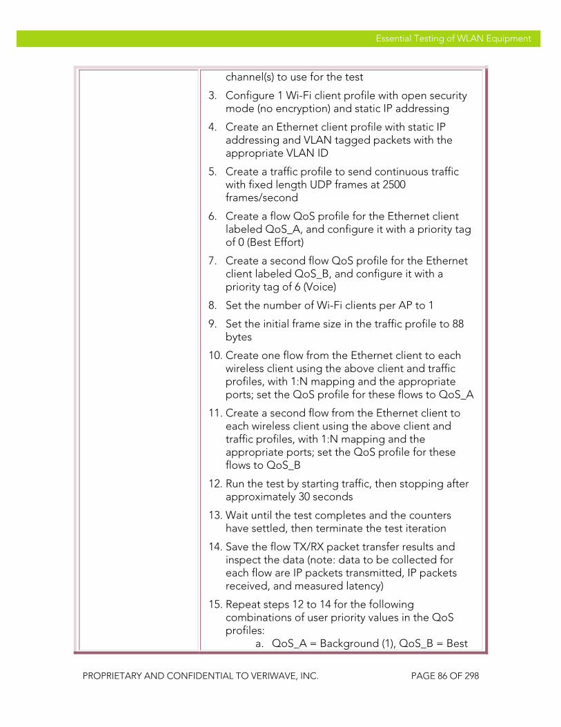
VeriWave, Inc. Essential Testing of WLAN Equipment
PROPRIETARY AND CONFIDENTIAL TO VERIWAVE, INC. PAGE 86 OF 298
Essential Testing of WLAN Equipment
channel(s) to use for the test
3. Configure 1 Wi-Fi client profile with open security mode (no encryption) and static IP addressing
4. Create an Ethernet client profile with static IP addressing and VLAN tagged packets with the appropriate VLAN ID
5. Create a traffic profile to send continuous traffic with fixed length UDP frames at 2500 frames/second
6. Create a flow QoS profile for the Ethernet client labeled QoS_A, and configure it with a priority tag of 0 (Best Effort)
7. Create a second flow QoS profile for the Ethernet client labeled QoS_B, and configure it with a priority tag of 6 (Voice)
8. Set the number of Wi-Fi clients per AP to 1
9. Set the initial frame size in the traffic profile to 88 bytes
10. Create one flow from the Ethernet client to each wireless client using the above client and traffic profiles, with 1:N mapping and the appropriate ports; set the QoS profile for these flows to QoS_A
11. Create a second flow from the Ethernet client to each wireless client using the above client and traffic profiles, with 1:N mapping and the appropriate ports; set the QoS profile for these flows to QoS_B
12. Run the test by starting traffic, then stopping after approximately 30 seconds
13. Wait until the test completes and the counters have settled, then terminate the test iteration
14. Save the flow TX/RX packet transfer results and inspect the data (note: data to be collected for each flow are IP packets transmitted, IP packets received, and measured latency)
15. Repeat steps 12 to 14 for the following combinations of user priority values in the QoS profiles:
a. QoS_A = Background (1), QoS_B = Best

VeriWave, Inc. Essential Testing of WLAN Equipment
PROPRIETARY AND CONFIDENTIAL TO VERIWAVE, INC. PAGE 87 OF 298
Essential Testing of WLAN Equipment
Effort (0) b. QoS_A = Background (1), QoS_B = Video
(4) c. QoS_A = Best Effort (0), QoS_B = Video
(4) d. QoS_A = Best Effort (0), QoS_B = Voice
(6) e. QoS_A = Video (4), QoS_B = Voice (6)
16. Repeat steps 10 to 15 with 10 upstream and 10 downstream flows per wireless client, setting the traffic profile to transmit at 250 frames/second for each flow
17. Repeat steps 10 to 15 with 100 upstream and 100 downstream flows per wireless client, setting the traffic profile to transmit at 25 frames/second for each flow
18. Repeat steps 10 to 17 with frame sizes of 512 and 1518 bytes
19. Repeat steps 10 to 18 with WPA-PSK and WPA2-PSK security modes set in the Wi-Fi client profile
Test Priority High
Test Type QoS
Pass/Fail Criteria
A Carrier Grade SUT should clearly differentiate between flows with different 802.1D/802.11e priority classes. Flows assigned to higher-priority QoS classes should have at least 10% more frames forwarded and at least 5% lower latency than any flow in a lower-priority QoS class.
QTC-SP 004 Multi_Station_Downstream_Fairness
Title Verify fairness of downstream flows in same QoS level destined for different wireless clients
Purpose
Tests the fairness of the SUT QoS mechanisms when sending flows to multiple wireless stations per AP, when all flows possess the same user priority and WMM/802.11e TID. Multiple unidirectional (downstream) traffic flows are injected into the SUT and measured on the wireless side to verify that the SUT treats equal-priority flows destined for different clients
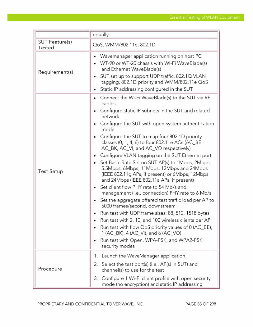
VeriWave, Inc. Essential Testing of WLAN Equipment
PROPRIETARY AND CONFIDENTIAL TO VERIWAVE, INC. PAGE 88 OF 298
Essential Testing of WLAN Equipment
equally.
SUT Feature(s) Tested
QoS, WMM/802.11e, 802.1D
Requirement(s)
• Wavemanager application running on host PC • WT-90 or WT-20 chassis with Wi-Fi WaveBlade(s)
and Ethernet WaveBlade(s) • SUT set up to support UDP traffic, 802.1Q VLAN
tagging, 802.1D priority and WMM/802.11e QoS • Static IP addressing configured in the SUT
Test Setup
• Connect the Wi-Fi WaveBlade(s) to the SUT via RF cables
• Configure static IP subnets in the SUT and related network
• Configure the SUT with open-system authentication mode
• Configure the SUT to map four 802.1D priority classes (0, 1, 4, 6) to four 802.11e ACs (AC_BE, AC_BK, AC_VI, and AC_VO respectively)
• Configure VLAN tagging on the SUT Ethernet port • Set Basic Rate Set on SUT AP(s) to 1Mbps, 2Mbps,
5.5Mbps, 6Mbps, 11Mbps, 12Mbps and 24Mbps (IEEE 802.11g APs, if present) or 6Mbps, 12Mbps and 24Mbps (IEEE 802.11a APs, if present)
• Set client flow PHY rate to 54 Mb/s and management (i.e., connection) PHY rate to 6 Mb/s
• Set the aggregate offered test traffic load per AP to 5000 frames/second, downstream
• Run test with UDP frame sizes: 88, 512, 1518 bytes • Run test with 2, 10, and 100 wireless clients per AP • Run test with flow QoS priority values of 0 (AC_BE),
1 (AC_BK), 4 (AC_VI), and 6 (AC_VO) • Run test with Open, WPA-PSK, and WPA2-PSK
security modes
Procedure
1. Launch the WaveManager application
2. Select the test port(s) (i.e., AP(s) in SUT) and channel(s) to use for the test
3. Configure 1 Wi-Fi client profile with open security mode (no encryption) and static IP addressing

VeriWave, Inc. Essential Testing of WLAN Equipment
PROPRIETARY AND CONFIDENTIAL TO VERIWAVE, INC. PAGE 89 OF 298
Essential Testing of WLAN Equipment
4. Create an Ethernet client profile with static IP addressing and VLAN tagged packets with the appropriate VLAN ID
5. Create a traffic profile to send continuous traffic with fixed length UDP frames at 2500 frames/second
6. Create a flow QoS profile for the Ethernet client and configure it to insert a priority tag of 0 (Best Effort)
7. Set the initial number of Wi-Fi clients per AP to 2
8. Set the initial frame size in the traffic profile to 88 bytes
9. Create one flow from the Ethernet client to each wireless client using the above client, traffic and QoS profiles, with 1:N mapping and the appropriate ports
10. Run the test by starting traffic, then stopping after approximately 30 seconds
11. Wait until the test completes and the counters have settled, then terminate the test iteration
12. Save the flow TX/RX packet transfer results and inspect the data (note: data to be collected for each flow are IP packets transmitted, IP packets received, and measured latency
13. Repeat steps 10 to 12 with flow QoS profile user priority values set to 1 (AC_BK), 4 (AC_VI), and 6 (AC_VO)
14. Repeat steps 10 to 13 with 10 wireless clients per AP, setting the traffic profile to transmit at 250 frames/second for each flow
15. Repeat steps 10 to 13 with 100 wireless clients per AP, setting the traffic profile to transmit at 25 frames/second for each flow
16. Repeat steps 8 to 15 with frame sizes of 512 and 1518 bytes
17. Repeat steps 8 to 15 with WPA-PSK and WPA2-PSK security modes set in the Wi-Fi client profile
Test Priority Mandatory

VeriWave, Inc. Essential Testing of WLAN Equipment
PROPRIETARY AND CONFIDENTIAL TO VERIWAVE, INC. PAGE 90 OF 298
Essential Testing of WLAN Equipment
Test Type QoS
Pass/Fail Criteria
A Carrier Grade SUT must provide equal QoS treatment for all flows in the above test, as they are assigned equal 802.1D/802.11e priority classes (even though they terminate on different wireless clients). All flows should therefore have receive frame values within 10% of each other, and should have latency values within 5% of each other.
QTC-SP 005 Multi_Station_Downstream_Priority
Title Verify prioritization of downstream flows in different QoS levels destined for different wireless clients
Purpose
Tests the functioning of the SUT QoS mechanisms when differentiating downstream flows at different priority levels that are being sent to multiple wireless stations per AP. Multiple unidirectional (downstream) traffic flows are injected into the SUT and measured on the wireless side to verify that the SUT handles different-priority flows according to their user priority levels.
SUT Feature(s) Tested
QoS, WMM/802.11e, 802.1D
Requirement(s)
• Wavemanager application running on host PC • WT-90 or WT-20 chassis with Wi-Fi WaveBlade(s)
and Ethernet WaveBlade(s) • SUT set up to support UDP traffic, 802.1Q VLAN
tagging, 802.1D priority and WMM/802.11e QoS • Static IP addressing configured in the SUT
Test Setup
• Connect the Wi-Fi WaveBlade(s) to the SUT via RF cables
• Configure static IP subnets in the SUT and related network
• Configure the SUT with open-system authentication mode
• Configure the SUT to map four 802.1D priority classes (0, 1, 4, 6) to four 802.11e ACs (AC_BE, AC_BK, AC_VI, and AC_VO respectively)
• Configure VLAN tagging on the SUT Ethernet port • Set Basic Rate Set on SUT AP(s) to 1Mbps, 2Mbps,
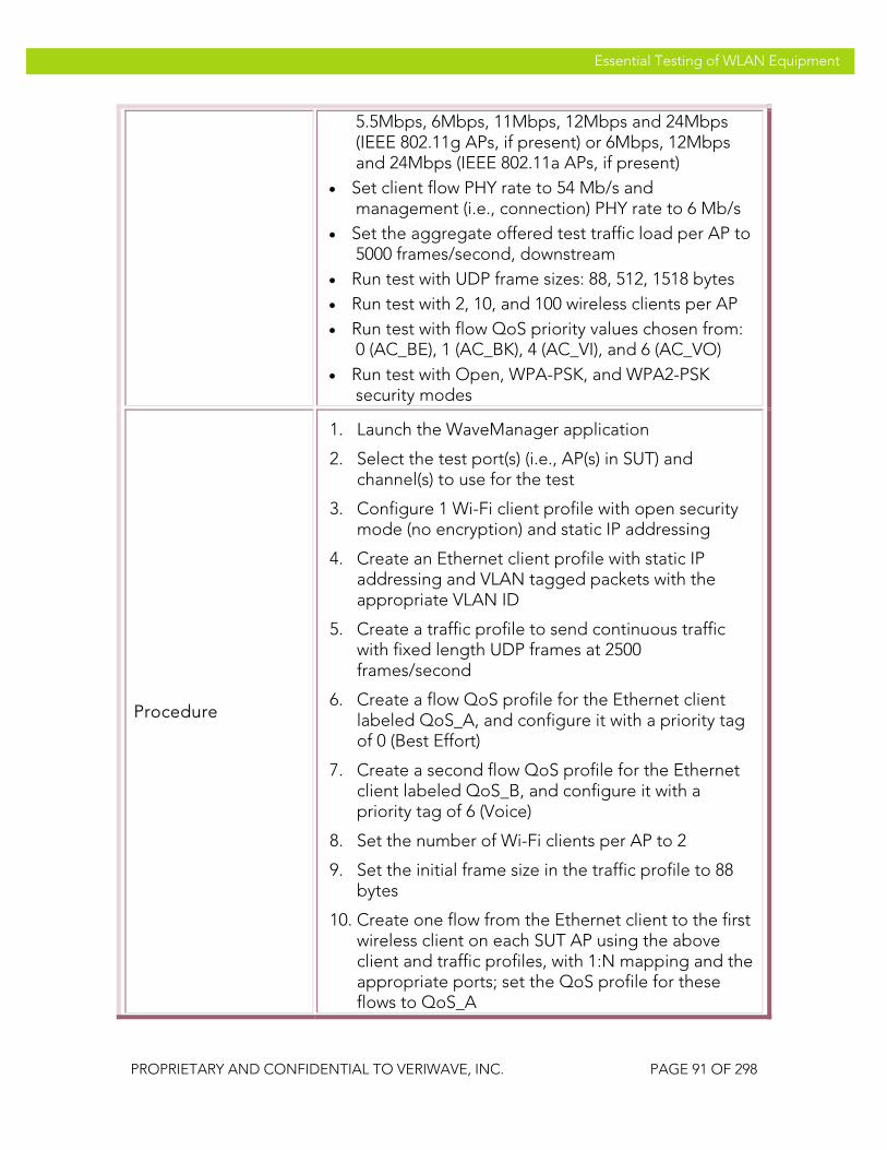
VeriWave, Inc. Essential Testing of WLAN Equipment
PROPRIETARY AND CONFIDENTIAL TO VERIWAVE, INC. PAGE 91 OF 298
Essential Testing of WLAN Equipment
5.5Mbps, 6Mbps, 11Mbps, 12Mbps and 24Mbps (IEEE 802.11g APs, if present) or 6Mbps, 12Mbps and 24Mbps (IEEE 802.11a APs, if present)
• Set client flow PHY rate to 54 Mb/s and management (i.e., connection) PHY rate to 6 Mb/s
• Set the aggregate offered test traffic load per AP to 5000 frames/second, downstream
• Run test with UDP frame sizes: 88, 512, 1518 bytes • Run test with 2, 10, and 100 wireless clients per AP • Run test with flow QoS priority values chosen from:
0 (AC_BE), 1 (AC_BK), 4 (AC_VI), and 6 (AC_VO) • Run test with Open, WPA-PSK, and WPA2-PSK
security modes
Procedure
1. Launch the WaveManager application
2. Select the test port(s) (i.e., AP(s) in SUT) and channel(s) to use for the test
3. Configure 1 Wi-Fi client profile with open security mode (no encryption) and static IP addressing
4. Create an Ethernet client profile with static IP addressing and VLAN tagged packets with the appropriate VLAN ID
5. Create a traffic profile to send continuous traffic with fixed length UDP frames at 2500 frames/second
6. Create a flow QoS profile for the Ethernet client labeled QoS_A, and configure it with a priority tag of 0 (Best Effort)
7. Create a second flow QoS profile for the Ethernet client labeled QoS_B, and configure it with a priority tag of 6 (Voice)
8. Set the number of Wi-Fi clients per AP to 2
9. Set the initial frame size in the traffic profile to 88 bytes
10. Create one flow from the Ethernet client to the first wireless client on each SUT AP using the above client and traffic profiles, with 1:N mapping and the appropriate ports; set the QoS profile for these flows to QoS_A
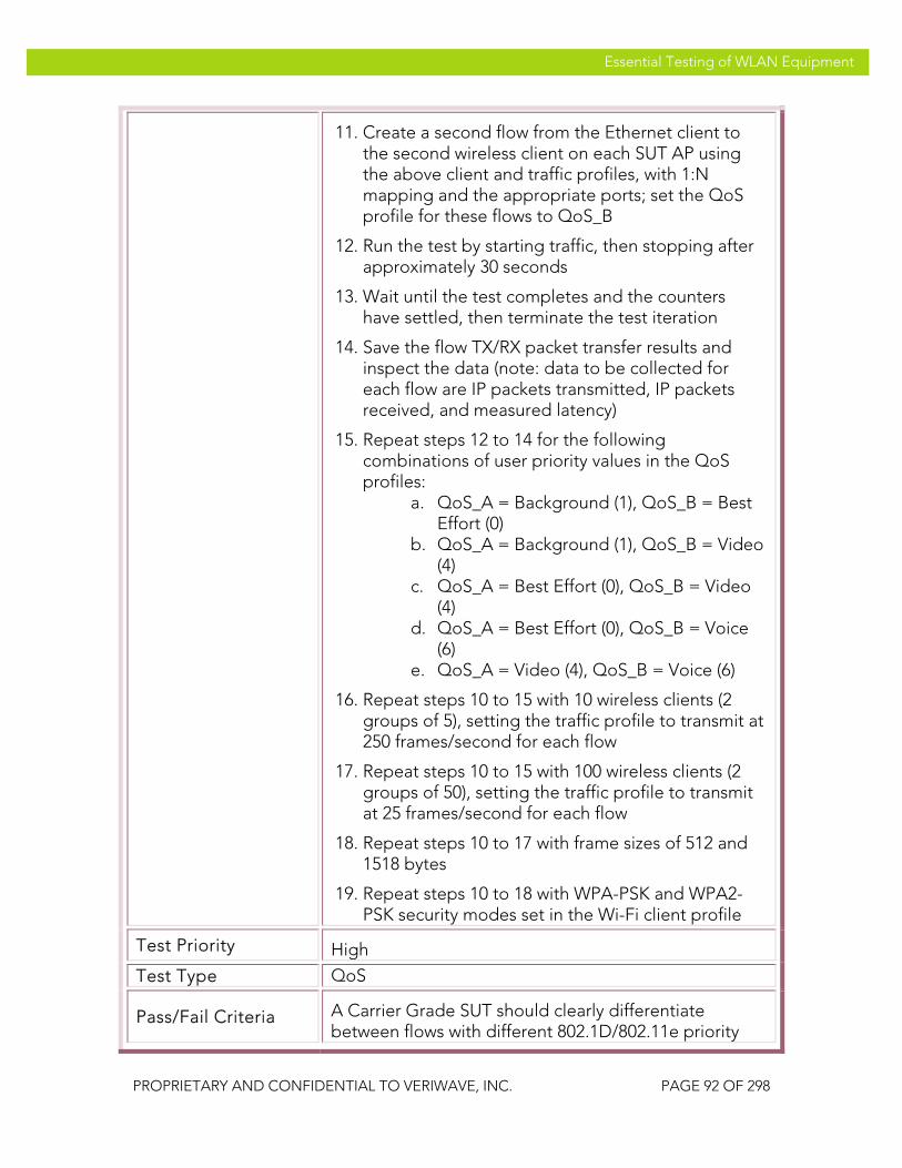
VeriWave, Inc. Essential Testing of WLAN Equipment
PROPRIETARY AND CONFIDENTIAL TO VERIWAVE, INC. PAGE 92 OF 298
Essential Testing of WLAN Equipment
11. Create a second flow from the Ethernet client to the second wireless client on each SUT AP using the above client and traffic profiles, with 1:N mapping and the appropriate ports; set the QoS profile for these flows to QoS_B
12. Run the test by starting traffic, then stopping after approximately 30 seconds
13. Wait until the test completes and the counters have settled, then terminate the test iteration
14. Save the flow TX/RX packet transfer results and inspect the data (note: data to be collected for each flow are IP packets transmitted, IP packets received, and measured latency)
15. Repeat steps 12 to 14 for the following combinations of user priority values in the QoS profiles:
a. QoS_A = Background (1), QoS_B = Best Effort (0)
b. QoS_A = Background (1), QoS_B = Video (4)
c. QoS_A = Best Effort (0), QoS_B = Video (4)
d. QoS_A = Best Effort (0), QoS_B = Voice (6)
e. QoS_A = Video (4), QoS_B = Voice (6)
16. Repeat steps 10 to 15 with 10 wireless clients (2 groups of 5), setting the traffic profile to transmit at 250 frames/second for each flow
17. Repeat steps 10 to 15 with 100 wireless clients (2 groups of 50), setting the traffic profile to transmit at 25 frames/second for each flow
18. Repeat steps 10 to 17 with frame sizes of 512 and 1518 bytes
19. Repeat steps 10 to 18 with WPA-PSK and WPA2-PSK security modes set in the Wi-Fi client profile
Test Priority High
Test Type QoS
Pass/Fail Criteria A Carrier Grade SUT should clearly differentiate between flows with different 802.1D/802.11e priority

VeriWave, Inc. Essential Testing of WLAN Equipment
PROPRIETARY AND CONFIDENTIAL TO VERIWAVE, INC. PAGE 93 OF 298
Essential Testing of WLAN Equipment
classes. Flows assigned to higher-priority QoS classes should have at least 10% more frames forwarded and at least 5% lower latency than any flow in a lower-priority QoS class, regardless of which client terminates the flows.
QTC-SP 006 Multi_Station_Upstream_Fairness
Title Verify fairness of upstream flows in same QoS level originating from different wireless clients
Purpose
Tests the fairness of the SUT QoS mechanisms when forwarding flows received from multiple wireless stations per AP, when all flows possess the same user priority and WMM/802.11e TID. Multiple unidirectional (downstream) traffic flows are injected into the SUT and measured on the wireless side to verify that the SUT treats equal-priority flows destined for different clients equally.
SUT Feature(s) Tested
QoS, WMM/802.11e, 802.1D
Requirement(s)
• Wavemanager application running on host PC • WT-90 or WT-20 chassis with Wi-Fi WaveBlade(s)
and Ethernet WaveBlade(s) • SUT set up to support UDP traffic, 802.1Q VLAN
tagging, 802.1D priority and WMM/802.11e QoS • Static IP addressing configured in the SUT
Test Setup
• Connect the Wi-Fi WaveBlade(s) to the SUT via RF cables
• Configure static IP subnets in the SUT and related network
• Configure the SUT with open-system authentication mode
• Configure the SUT to map four 802.1D priority classes (0, 1, 4, 6) to four 802.11e ACs (AC_BE, AC_BK, AC_VI, and AC_VO respectively)
• Configure VLAN tagging on the SUT Ethernet port • Set Basic Rate Set on SUT AP(s) to 1Mbps, 2Mbps,
5.5Mbps, 6Mbps, 11Mbps, 12Mbps and 24Mbps (IEEE 802.11g APs, if present) or 6Mbps, 12Mbps and 24Mbps (IEEE 802.11a APs, if present)

VeriWave, Inc. Essential Testing of WLAN Equipment
PROPRIETARY AND CONFIDENTIAL TO VERIWAVE, INC. PAGE 94 OF 298
Essential Testing of WLAN Equipment
• Set client flow PHY rate to 54 Mb/s and management (i.e., connection) PHY rate to 6 Mb/s
• Set the aggregate offered test traffic load per AP to 5000 frames/second, downstream
• Run test with UDP frame sizes: 88, 512, 1518 bytes • Run test with 2, 10, and 100 wireless clients per AP • Run test with flow QoS priority values of 0 (AC_BE),
1 (AC_BK), 4 (AC_VI), and 6 (AC_VO) • Run test with Open, WPA-PSK, and WPA2-PSK
security modes
Procedure
1. Launch the WaveManager application
2. Select the test port(s) (i.e., AP(s) in SUT) and channel(s) to use for the test
3. Configure 1 Wi-Fi client profile with open security mode (no encryption) and static IP addressing
4. Create an Ethernet client profile with static IP addressing and VLAN tagged packets with the appropriate VLAN ID
5. Create a traffic profile to send continuous traffic with fixed length UDP frames at 2500 frames/second
6. Create a flow QoS profile for the wireless clients and configure it use priority of 0 (Best Effort) and WMM/802.11e QoS with parameters being adopted from the AP
7. Set the initial number of Wi-Fi clients per AP to 2
8. Set the initial frame size in the traffic profile to 88 bytes
9. Create one flow from each wireless client to the Ethernet client using the above client, traffic and QoS profiles, with N:1 mapping and the appropriate ports
10. Run the test by starting traffic, then stopping after approximately 30 seconds
11. Wait until the test completes and the counters have settled, then terminate the test iteration
12. Save the flow TX/RX packet transfer results and inspect the data (note: data to be collected for

VeriWave, Inc. Essential Testing of WLAN Equipment
PROPRIETARY AND CONFIDENTIAL TO VERIWAVE, INC. PAGE 95 OF 298
Essential Testing of WLAN Equipment
each flow are IP packets transmitted, IP packets received, and measured latency
13. Repeat steps 10 to 12 with flow QoS profile user priority values set to 1 (AC_BK), 4 (AC_VI), and 6 (AC_VO)
14. Repeat steps 10 to 13 with 10 wireless clients per AP, setting the traffic profile to transmit at 250 frames/second for each flow
15. Repeat steps 10 to 13 with 100 wireless clients per AP, setting the traffic profile to transmit at 25 frames/second for each flow
16. Repeat steps 8 to 15 with frame sizes of 512 and 1518 bytes
17. Repeat steps 8 to 15 with WPA-PSK and WPA2-PSK security modes set in the Wi-Fi client profile
Test Priority High
Test Type QoS
Pass/Fail Criteria
A Carrier Grade SUT must provide equal QoS treatment for all flows in the above test, as they are assigned equal 802.1D/802.11e priority classes (even though they originate from different wireless clients). All flows should therefore have receive frame values within 10% of each other, and should have latency values within 5% of each other.
QTC-SP 007 Multi_Station_Upstream_Priority
Title Verify prioritization of upstream flows in different QoS levels originating from different wireless clients
Purpose
Tests the functioning of the SUT QoS mechanisms when differentiating upstream flows received from different wireless clients at different priority levels. Multiple unidirectional (upstream) traffic flows are injected into the SUT and measured on the Ethernet side to verify that the SUT handles different-priority flows according to their user priority levels.
SUT Feature(s) Tested
QoS, WMM/802.11e, 802.1D
Requirement(s) • Wavemanager application running on host PC
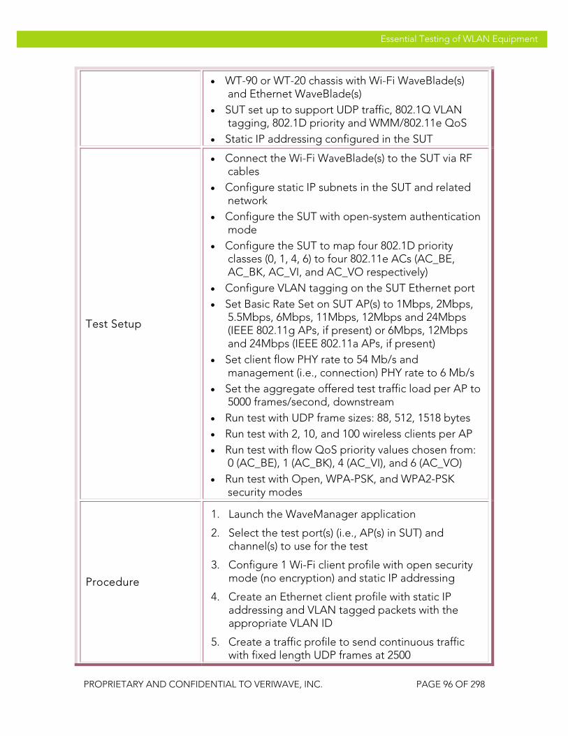
VeriWave, Inc. Essential Testing of WLAN Equipment
PROPRIETARY AND CONFIDENTIAL TO VERIWAVE, INC. PAGE 96 OF 298
Essential Testing of WLAN Equipment
• WT-90 or WT-20 chassis with Wi-Fi WaveBlade(s) and Ethernet WaveBlade(s)
• SUT set up to support UDP traffic, 802.1Q VLAN tagging, 802.1D priority and WMM/802.11e QoS
• Static IP addressing configured in the SUT
Test Setup
• Connect the Wi-Fi WaveBlade(s) to the SUT via RF cables
• Configure static IP subnets in the SUT and related network
• Configure the SUT with open-system authentication mode
• Configure the SUT to map four 802.1D priority classes (0, 1, 4, 6) to four 802.11e ACs (AC_BE, AC_BK, AC_VI, and AC_VO respectively)
• Configure VLAN tagging on the SUT Ethernet port • Set Basic Rate Set on SUT AP(s) to 1Mbps, 2Mbps,
5.5Mbps, 6Mbps, 11Mbps, 12Mbps and 24Mbps (IEEE 802.11g APs, if present) or 6Mbps, 12Mbps and 24Mbps (IEEE 802.11a APs, if present)
• Set client flow PHY rate to 54 Mb/s and management (i.e., connection) PHY rate to 6 Mb/s
• Set the aggregate offered test traffic load per AP to 5000 frames/second, downstream
• Run test with UDP frame sizes: 88, 512, 1518 bytes • Run test with 2, 10, and 100 wireless clients per AP • Run test with flow QoS priority values chosen from:
0 (AC_BE), 1 (AC_BK), 4 (AC_VI), and 6 (AC_VO) • Run test with Open, WPA-PSK, and WPA2-PSK
security modes
Procedure
1. Launch the WaveManager application
2. Select the test port(s) (i.e., AP(s) in SUT) and channel(s) to use for the test
3. Configure 1 Wi-Fi client profile with open security mode (no encryption) and static IP addressing
4. Create an Ethernet client profile with static IP addressing and VLAN tagged packets with the appropriate VLAN ID
5. Create a traffic profile to send continuous traffic with fixed length UDP frames at 2500

VeriWave, Inc. Essential Testing of WLAN Equipment
PROPRIETARY AND CONFIDENTIAL TO VERIWAVE, INC. PAGE 97 OF 298
Essential Testing of WLAN Equipment
frames/second
6. Create a flow QoS profile for the wireless client labeled QoS_A, and configure it with a user priority of 0 (Best Effort), WMM enabled, adopt parameters from the AP, and no CAC handshake
7. Create a second flow QoS profile for the Ethernet client labeled QoS_B, and configure it with a user priority of 6 (Voice), WMM enabled, adopt parameters from the AP, and no CAC handshake
8. Set the number of Wi-Fi clients per AP to 2
9. Set the initial frame size in the traffic profile to 88 bytes
10. Create one flow from the first wireless client on each SUT AP to the Ethernet client using the above client and traffic profiles, with 1:N mapping and the appropriate ports; set the QoS profile for these flows to QoS_A
11. Create a second flow from the second wireless client on each SUT AP to the Ethernet client using the above client and traffic profiles, with 1:N mapping and the appropriate ports; set the QoS profile for these flows to QoS_B
12. Run the test by starting traffic, then stopping after approximately 30 seconds
13. Wait until the test completes and the counters have settled, then terminate the test iteration
14. Save the flow TX/RX packet transfer results and inspect the data (note: data to be collected for each flow are IP packets transmitted, IP packets received, and measured latency)
15. Repeat steps 12 to 14 for the following combinations of user priority values in the QoS profiles:
a. QoS_A = Background (1), QoS_B = Best Effort (0)
b. QoS_A = Background (1), QoS_B = Video (4)
c. QoS_A = Best Effort (0), QoS_B = Video (4)
d. QoS_A = Best Effort (0), QoS_B = Voice

VeriWave, Inc. Essential Testing of WLAN Equipment
PROPRIETARY AND CONFIDENTIAL TO VERIWAVE, INC. PAGE 98 OF 298
Essential Testing of WLAN Equipment
(6) e. QoS_A = Video (4), QoS_B = Voice (6)
16. Repeat steps 10 to 15 with 10 wireless clients (2 groups of 5), setting the traffic profile to transmit at 250 frames/second for each flow
17. Repeat steps 10 to 15 with 100 wireless clients (2 groups of 50), setting the traffic profile to transmit at 25 frames/second for each flow
18. Repeat steps 10 to 17 with frame sizes of 512 and 1518 bytes
19. Repeat steps 10 to 18 with WPA-PSK and WPA2-PSK security modes set in the Wi-Fi client profile
Test Priority High
Test Type QoS
Pass/Fail Criteria
A Carrier Grade SUT should clearly differentiate between flows with different 802.1D/802.11e priority classes originating from different clients. Flows assigned to higher-priority QoS classes should have at least 10% more frames forwarded and at least 5% lower latency than any flow in a lower-priority QoS class, regardless of which client originates the flows.
QTC-SP 008 Legacy_QoS_Coexistence
Title Verify coexistence of QoS and non-QoS (legacy) clients
Purpose Tests the SUT to verify that it can properly differentiate traffic to and from a mixed environment of WMM/802.11e QoS and non-QoS stations.
SUT Feature(s) Tested
QoS, WMM/802.11e, 802.1D, legacy interworking
Requirement(s)
• Wavemanager application running on host PC • WT-90 or WT-20 chassis with Wi-Fi WaveBlade(s)
and Ethernet WaveBlade(s) • SUT set up to support UDP traffic, 802.1Q VLAN
tagging, 802.1D priority and WMM/802.11e QoS • Static IP addressing configured in the SUT
Test Setup • Connect the Wi-Fi WaveBlade(s) to the SUT via RF cables

VeriWave, Inc. Essential Testing of WLAN Equipment
PROPRIETARY AND CONFIDENTIAL TO VERIWAVE, INC. PAGE 99 OF 298
Essential Testing of WLAN Equipment
• Configure static IP subnets in the SUT and related network
• Configure the SUT with open-system authentication mode
• Configure the SUT to map four 802.1D priority classes (0, 1, 4, 6) to four WMM/802.11e ACs (AC_BE, AC_BK, AC_VI, and AC_VO respectively)
• Configure the SUT to map traffic to/from non-QoS clients to the best-efforts traffic class
• Configure VLAN tagging on the SUT Ethernet port • Set Basic Rate Set on SUT AP(s) to 1Mbps, 2Mbps,
5.5Mbps, 6Mbps, 11Mbps, 12Mbps and 24Mbps (IEEE 802.11g APs, if present) or 6Mbps, 12Mbps and 24Mbps (IEEE 802.11a APs, if present)
• Set client flow PHY rate to 54 Mb/s and management (i.e., connection) PHY rate to 6 Mb/s
• Set the aggregate offered test traffic load per AP to 4500 frames/second, downstream
• Run test with UDP frame sizes: 88, 512, 1518 bytes • Run test with 3, 30, and 90 wireless clients per AP • Run test with flow QoS priority values of 0 (AC_BE),
1 (AC_BK), 4 (AC_VI), and 6 (AC_VO) • Run test with Open, WPA-PSK, and WPA2-PSK
security modes
Procedure
1. Launch the WaveManager application
2. Select the test port(s) (i.e., AP(s) in SUT) and channel(s) to use for the test
3. Configure 1 Wi-Fi client profile with open security mode (no encryption) and static IP addressing
4. Create an Ethernet client profile with static IP addressing and VLAN tagged packets with the appropriate VLAN ID
5. Create a traffic profile to send continuous traffic with fixed length UDP frames at 1500 frames/second
6. Create a flow QoS profile for the Ethernet client labeled QoS_A, and configure it with a priority tag of 0 (Best Effort)
7. Create a second flow QoS profile for the Ethernet
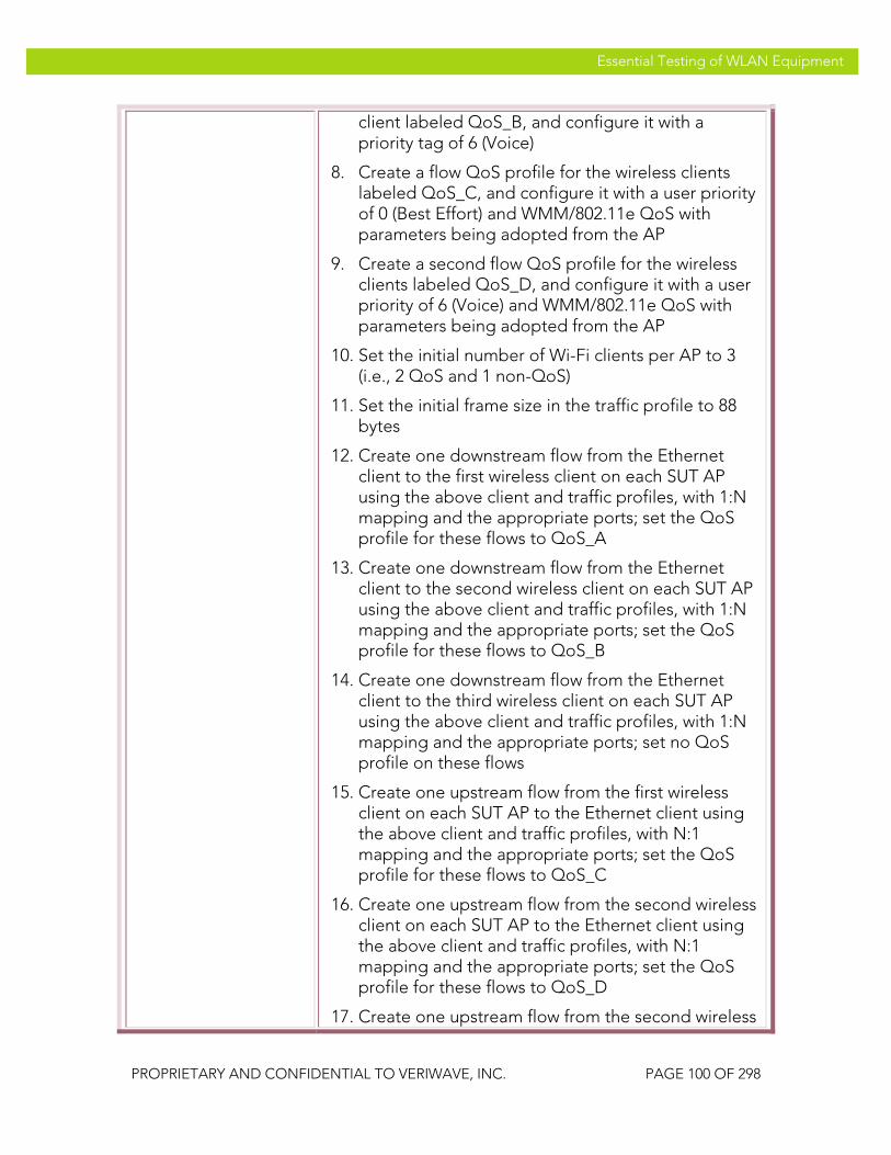
VeriWave, Inc. Essential Testing of WLAN Equipment
PROPRIETARY AND CONFIDENTIAL TO VERIWAVE, INC. PAGE 100 OF 298
Essential Testing of WLAN Equipment
client labeled QoS_B, and configure it with a priority tag of 6 (Voice)
8. Create a flow QoS profile for the wireless clients labeled QoS_C, and configure it with a user priority of 0 (Best Effort) and WMM/802.11e QoS with parameters being adopted from the AP
9. Create a second flow QoS profile for the wireless clients labeled QoS_D, and configure it with a user priority of 6 (Voice) and WMM/802.11e QoS with parameters being adopted from the AP
10. Set the initial number of Wi-Fi clients per AP to 3 (i.e., 2 QoS and 1 non-QoS)
11. Set the initial frame size in the traffic profile to 88 bytes
12. Create one downstream flow from the Ethernet client to the first wireless client on each SUT AP using the above client and traffic profiles, with 1:N mapping and the appropriate ports; set the QoS profile for these flows to QoS_A
13. Create one downstream flow from the Ethernet client to the second wireless client on each SUT AP using the above client and traffic profiles, with 1:N mapping and the appropriate ports; set the QoS profile for these flows to QoS_B
14. Create one downstream flow from the Ethernet client to the third wireless client on each SUT AP using the above client and traffic profiles, with 1:N mapping and the appropriate ports; set no QoS profile on these flows
15. Create one upstream flow from the first wireless client on each SUT AP to the Ethernet client using the above client and traffic profiles, with N:1 mapping and the appropriate ports; set the QoS profile for these flows to QoS_C
16. Create one upstream flow from the second wireless client on each SUT AP to the Ethernet client using the above client and traffic profiles, with N:1 mapping and the appropriate ports; set the QoS profile for these flows to QoS_D
17. Create one upstream flow from the second wireless
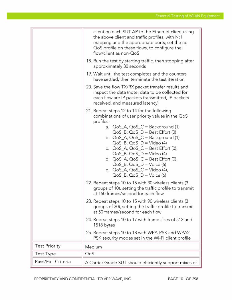
VeriWave, Inc. Essential Testing of WLAN Equipment
PROPRIETARY AND CONFIDENTIAL TO VERIWAVE, INC. PAGE 101 OF 298
Essential Testing of WLAN Equipment
client on each SUT AP to the Ethernet client using the above client and traffic profiles, with N:1 mapping and the appropriate ports; set the no QoS profile on these flows, to configure the flow/client as non-QoS
18. Run the test by starting traffic, then stopping after approximately 30 seconds
19. Wait until the test completes and the counters have settled, then terminate the test iteration
20. Save the flow TX/RX packet transfer results and inspect the data (note: data to be collected for each flow are IP packets transmitted, IP packets received, and measured latency)
21. Repeat steps 12 to 14 for the following combinations of user priority values in the QoS profiles:
a. QoS_A, QoS_C = Background (1), QoS_B, QoS_D = Best Effort (0)
b. QoS_A, QoS_C = Background (1), QoS_B, QoS_D = Video (4)
c. QoS_A, QoS_C = Best Effort (0), QoS_B, QoS_D = Video (4)
d. QoS_A, QoS_C = Best Effort (0), QoS_B, QoS_D = Voice (6)
e. QoS_A, QoS_C = Video (4), QoS_B, QoS_D = Voice (6)
22. Repeat steps 10 to 15 with 30 wireless clients (3 groups of 10), setting the traffic profile to transmit at 150 frames/second for each flow
23. Repeat steps 10 to 15 with 90 wireless clients (3 groups of 30), setting the traffic profile to transmit at 50 frames/second for each flow
24. Repeat steps 10 to 17 with frame sizes of 512 and 1518 bytes
25. Repeat steps 10 to 18 with WPA-PSK and WPA2-PSK security modes set in the Wi-Fi client profile
Test Priority Medium
Test Type QoS
Pass/Fail Criteria A Carrier Grade SUT should efficiently support mixes of

VeriWave, Inc. Essential Testing of WLAN Equipment
PROPRIETARY AND CONFIDENTIAL TO VERIWAVE, INC. PAGE 102 OF 298
Essential Testing of WLAN Equipment
QoS and non-QoS clients. Flows within the same QoS class should have receive frame values within 10% of each other, and should have latency values within 5% of each other. Flows assigned to higher-priority QoS classes should have at least 10% more frames forwarded and at least 5% lower latency than any flow in a lower-priority QoS class, regardless of which client originates the flows. Flows to or from a non-QoS station should be treated as Best Efforts and should be differentiated properly compared to traffic to or from QoS stations.
QTC-SP 009 Basic_Call_Admission_Control
Title Verify basic call admission control support via WMM/802.11e
Purpose
Test the SUT’s ability to limit the number of WMM-enabled clients according to the advertised bandwidth requirements of these clients. Upstream traffic is sent from the connected WMM clients to verify that admitted clients can maintain their QoS and bandwidth needs. This test also serves as a baseline for the remainder of the CAC functionality test cases.
SUT Feature(s) Tested
QoS, WMM/802.11e, CAC
Requirement(s)
• CAC test script running on host PC • WT-90 or WT-20 chassis with Wi-Fi WaveBlade(s)
and Ethernet WaveBlade(s) • SUT set up to support UDP traffic and
WMM/802.11e QoS with CAC • Static IP addressing configured in the SUT
Test Setup
• Connect the Wi-Fi WaveBlade(s) to the SUT via RF cables
• Configure static IP subnets in the SUT and related network
• Configure the SUT with open-system authentication mode
• Configure the SUT to map four 802.1D priority classes (0, 1, 4, 6) to four 802.11e ACs (AC_BE, AC_BK, AC_VI, and AC_VO respectively)
• Enable CAC on the SUT and set limits as follows:

VeriWave, Inc. Essential Testing of WLAN Equipment
PROPRIETARY AND CONFIDENTIAL TO VERIWAVE, INC. PAGE 103 OF 298
Essential Testing of WLAN Equipment
• AC_BE: maximum data rate = 5 Mb/s • AC_BK: maximum data rate = 5 Mb/s • AC_Vi: maximum data rate = 7 Mb/s • AC_VO: maximum data rate = 3 Mb/s
• Set Basic Rate Set on SUT AP(s) to 1Mbps, 2Mbps, 5.5Mbps, 6Mbps, 11Mbps, 12Mbps and 24Mbps (IEEE 802.11g APs, if present) or 6Mbps, 12Mbps and 24Mbps (IEEE 802.11a APs, if present)
• Set client flow PHY rate to 54 Mb/s and management (i.e., connection) PHY rate to 6 Mb/s
• Set the QoS configuration (i.e., TSPEC parameters) in the CAC test script to match those of the SUT with the exception of mean data rate
• Run test with UDP frame sizes: 512, 1024, 1518 bytes• Run test with 1, 10, and 100 WMM clients per SUT
AP • Run test with QoS values of 0 (AC_BE), 1 (AC_BK), 4
(AC_VI), and 6 (AC_VO) • Run test with Open, WPA-PSK, and WPA2-PSK
security modes
Procedure
1. Configure the CAC test script parameters according to the trial being run, as per steps 2 through 8
2. Select the test port(s) (i.e., AP(s) in SUT) and channel(s) to use for the test
3. Configure 1 group of Wi-Fi clients per AP with WMM/CAC enabled
4. Configure the initial security mode for the clients in the group to Open
5. Configure the initial number of clients per group to be 1
6. Configure the initial AC for the group to be 0 (AC_BE)
7. Configure the traffic type for the group as UDP with a frame size of 512 bytes
8. Configure the aggregate mean data rate for the client(s) in the group to be ((MDR – 500 kb/s) / N), where MDR is the maximum data rate defined for the corresponding AC in the SUT (see above) and N is the number of clients in the group

VeriWave, Inc. Essential Testing of WLAN Equipment
PROPRIETARY AND CONFIDENTIAL TO VERIWAVE, INC. PAGE 104 OF 298
Essential Testing of WLAN Equipment
9. Run the script and record the output
10. Now configure the aggregate mean data rate for the client(s) in the group to be ((MDR + 2000 kb/s) / N), where MDR and N are as above (i.e., exceed the data rate allocated)
11. Run the script again and record the output
12. Repeat steps 8 to 11 with frame sizes of 1024 and 1518 bytes
13. Repeat steps 7 to 12 with AC set to 1 (AC_BK), 4 (AC_VI), and 6 (AC_VO)
14. Repeat steps 6 to 13 with the number of clients in the group set to 10 and 100
15. Repeat steps 5 to 14 with WPA-PSK and WPA2-PSK security modes
Test Priority High
Test Type QoS
Pass/Fail Criteria
A Carrier Grade SUT should implement CAC. All of the wireless clients should successfully associate with the SUT and pass traffic when their aggregate mean data rate is less than the configured maximum data rate in the SUT for that traffic class. Some of the wireless clients should fail to associate with the SUT when their aggregate mean data rate is greater than the configured maximum data rate for that traffic class. The packet loss must be less than 5% in the situation where all of the wireless clients associate (i.e., when they satisfy the CAC requirements).
QTC-SP 010 Call_Admission_Control_Denial_PHY_Rate
Title Verify that CAC operates to deny admission based on minimum PHY rate
Purpose
Test the SUT’s ability to deny admission to WMM-enabled clients based on the advertised minimum PHY rate requirements of these clients. Upstream traffic is sent from the connected WMM clients to verify that admitted clients can maintain their QoS and bandwidth needs.

VeriWave, Inc. Essential Testing of WLAN Equipment
PROPRIETARY AND CONFIDENTIAL TO VERIWAVE, INC. PAGE 105 OF 298
Essential Testing of WLAN Equipment
SUT Feature(s) Tested
QoS, WMM/802.11e, CAC, admission denial based on PHY rate
Requirement(s)
• CAC test script running on host PC • WT-90 or WT-20 chassis with Wi-Fi WaveBlade(s)
and Ethernet WaveBlade(s) • SUT set up to support UDP traffic and
WMM/802.11e QoS with CAC • Static IP addressing configured in the SUT
Test Setup
• Connect the Wi-Fi WaveBlade(s) to the SUT via RF cables
• Configure static IP subnets in the SUT and related network
• Configure the SUT with open-system authentication mode
• Configure the SUT to map four 802.1D priority classes (0, 1, 4, 6) to four 802.11e ACs (AC_BE, AC_BK, AC_VI, and AC_VO respectively)
• Enable CAC on the SUT and set the Minimum PHY Rate TSPEC parameter to 12 Mb/s
• Set Basic Rate Set on SUT AP(s) to 1Mbps, 2Mbps, 5.5Mbps, 6Mbps, 11Mbps, 12Mbps and 24Mbps (IEEE 802.11g APs, if present) or 6Mbps, 12Mbps and 24Mbps (IEEE 802.11a APs, if present)
• Set client flow PHY rate to 54 Mb/s and management (i.e., connection) PHY rate to 6 Mb/s
• Set the QoS configuration (i.e., TSPEC parameters) in the CAC test script to match those of the SUT with the exception of minimum PHY rate
• Run test with UDP frame sizes: 512, 1024, 1518 bytes• Run test with 1, 10, and 100 WMM clients per SUT
AP • Run test with QoS values of 0 (AC_BE), 1 (AC_BK), 4
(AC_VI), and 6 (AC_VO) • Run test with Open, WPA-PSK, and WPA2-PSK
security modes
Procedure
1. Configure the CAC test script parameters according to the trial being run, as per steps 2 through 8
2. Select the test port(s) (i.e., AP(s) in SUT) and channel(s) to use for the test

VeriWave, Inc. Essential Testing of WLAN Equipment
PROPRIETARY AND CONFIDENTIAL TO VERIWAVE, INC. PAGE 106 OF 298
Essential Testing of WLAN Equipment
3. Configure 1 group of Wi-Fi clients per AP with WMM/CAC enabled
4. Configure the initial security mode for the clients in the group to Open
5. Configure the initial number of clients per group to be 1
6. Configure the initial AC for the group to be 0 (AC_BE)
7. Configure the traffic type for the group as UDP with a frame size of 512 bytes
8. Configure the aggregate mean data rate for the client(s) in the group to be ((MDR – 500 kb/s) / N), where MDR is the maximum data rate configured for the corresponding AC in the SUT and N is the number of clients in the group
9. Configure the minimum PHY rate for the client(s) in the group to be 12 Mb/s
10. Run the script and record the output
11. Now configure the minimum PHY rate for the client(s) in the group to be 6 Mb/s
12. Run the script again and record the output
13. Repeat steps 8 to 12 with frame sizes of 1024 and 1518 bytes
14. Repeat steps 7 to 13 with AC set to 1 (AC_BK), 4 (AC_VI), and 6 (AC_VO)
15. Repeat steps 6 to 14 with the number of clients in the group set to 10 and 100
16. Repeat steps 5 to 15 with WPA-PSK and WPA2-PSK security modes
Test Priority Low
Test Type QoS
Pass/Fail Criteria
All of the wireless clients should successfully associate with a Carrier Grade SUT and pass traffic when the requested minimum PHY data rate is greater than the configured minimum PHY data rate in the SUT for that traffic class. All of the wireless clients should fail to

VeriWave, Inc. Essential Testing of WLAN Equipment
PROPRIETARY AND CONFIDENTIAL TO VERIWAVE, INC. PAGE 107 OF 298
Essential Testing of WLAN Equipment
associate with the SUT when the configured PHY data rate is greater than the configured minimum PHY data rate. The packet loss must be less than 5% in the situation where all of the wireless clients associate (i.e., when they satisfy the CAC requirements).
QTC-SP 011 Call_Admission_Control_Denial_Utilization
Title Verify that CAC operates to deny admission based on actual bandwidth utilization within the SUT
Purpose
Test the SUT’s ability to limit the number of WMM-enabled clients according to the advertised bandwidth requirements of these clients, when SUT forwarding bandwidth is being occupied by a mixture of QoS/CAC and QoS/non-CAC clients. Upstream traffic is sent from the connected WMM clients to verify that admitted clients can maintain their QoS and bandwidth needs.
SUT Feature(s) Tested
QoS, WMM/802.11e, CAC, bandwidth management
Requirement(s)
• CAC test script running on host PC • WT-90 or WT-20 chassis with Wi-Fi WaveBlade(s)
and Ethernet WaveBlade(s) • SUT set up to support UDP traffic and
WMM/802.11e QoS with CAC • Static IP addressing configured in the SUT
Test Setup
• Connect the Wi-Fi WaveBlade(s) to the SUT via RF cables
• Configure static IP subnets in the SUT and related network
• Configure the SUT with open-system authentication mode
• Configure the SUT to map four 802.1D priority classes (0, 1, 4, 6) to four 802.11e ACs (AC_BE, AC_BK, AC_VI, and AC_VO respectively)
• Enable CAC on the SUT and set limits as follows: • AC_BE: maximum data rate = 5 Mb/s • AC_BK: maximum data rate = 5 Mb/s • AC_VI: maximum data rate = 7 Mb/s • AC_VO: maximum data rate = 3 Mb/s

VeriWave, Inc. Essential Testing of WLAN Equipment
PROPRIETARY AND CONFIDENTIAL TO VERIWAVE, INC. PAGE 108 OF 298
Essential Testing of WLAN Equipment
• Set Basic Rate Set on SUT AP(s) to 1Mbps, 2Mbps, 5.5Mbps, 6Mbps, 11Mbps, 12Mbps and 24Mbps (IEEE 802.11g APs, if present) or 6Mbps, 12Mbps and 24Mbps (IEEE 802.11a APs, if present)
• Set client flow PHY rate to 54 Mb/s and management (i.e., connection) PHY rate to 6 Mb/s
• Set the QoS configuration (i.e., TSPEC parameters) in the CAC test script to match those of the SUT
• Set 400 candidate WMM/CAC clients per SUT AP • Set 10 WMM/non-CAC clients per SUT AP • Run test with UDP frame sizes: 512, 1024, 1518 bytes• Run test with QoS values of 0 (AC_BE), 1 (AC_BK), 4
(AC_VI), and 6 (AC_VO) • Run test with Open, WPA-PSK, and WPA2-PSK
security modes
Procedure
1. Configure the CAC test script parameters according to the trial being run, as per steps 2 through 8
2. Select the test port(s) (i.e., AP(s) in SUT) and channel(s) to use for the test
3. Configure 1 group of 400 Wi-Fi clients per AP with WMM/CAC enabled
4. Configure a second group of 10 Wi-Fi clients per AP with WMM enabled without CAC (i.e., QoS but no TSPEC handshake)
5. Configure the initial security mode for the clients in both groups to Open
6. Configure the initial AC for both groups to be 0 (AC_BE)
7. Configure the traffic type for both groups as UDP with a frame size of 512 bytes
8. Configure the aggregate mean data rate for the client in the WMM group to be (MDR / 400), where MDR is the maximum data rate defined for the corresponding AC in the SUT (see above)
9. Configure the aggregate mean data rate for the clients in the WMM/non-CAC group to be 2000 kb/s
10. Run the script and record the output, specifically

VeriWave, Inc. Essential Testing of WLAN Equipment
PROPRIETARY AND CONFIDENTIAL TO VERIWAVE, INC. PAGE 109 OF 298
Essential Testing of WLAN Equipment
the number of WMM/CAC clients that failed to connect and the total bandwidth consumed by the connected clients
11. Repeat steps 8 to 10 with frame sizes of 1024 and 1518 bytes
12. Repeat steps 7 to 11 with AC set to 1 (AC_BK), 4 (AC_VI), and 6 (AC_VO)
13. Repeat steps 6 to 12 with WPA-PSK and WPA2-PSK security modes
Test Priority Medium
Test Type QoS
Pass/Fail Criteria
A Carrier Grade SUT should not admit further WMM/CAC clients if the admission would utilize more bandwidth than the configured maximum data rate for that traffic class. The packet loss must be less than 5% for all of the connected wireless clients (i.e., those that satisfy the CAC requirements).
QTC-SP 012 Call_Admission_Control_Codec_Type
Title Verify that CAC operates to deny admission based on actual bandwidth utilization within the SUT when utilizing a mixture of data and voice clients
Purpose
Test the SUT’s ability to limit the number of WMM-enabled clients according to the advertised bandwidth requirements of these clients, when SUT forwarding bandwidth is being occupied by a mixture of WMM/data and WMM/VoIP clients. Upstream traffic is sent from the connected WMM clients to verify that admitted clients can maintain their QoS and bandwidth needs.
SUT Feature(s) Tested
QoS, WMM/802.11e, CAC, bandwidth management, VoIP
Requirement(s)
• CAC test script running on host PC • WT-90 or WT-20 chassis with Wi-Fi WaveBlade(s)
and Ethernet WaveBlade(s) • SUT set up to support UDP traffic and
WMM/802.11e QoS with CAC • Static IP addressing configured in the SUT

VeriWave, Inc. Essential Testing of WLAN Equipment
PROPRIETARY AND CONFIDENTIAL TO VERIWAVE, INC. PAGE 110 OF 298
Essential Testing of WLAN Equipment
Test Setup
• Connect the Wi-Fi WaveBlade(s) to the SUT via RF cables
• Configure static IP subnets in the SUT and related network
• Configure the SUT with open-system authentication mode
• Configure the SUT to map four 802.1D priority classes (0, 1, 4, 6) to four 802.11e ACs (AC_BE, AC_BK, AC_VI, and AC_VO respectively)
• Enable CAC on the SUT and set limits as follows: • AC_VI: maximum data rate = 5 Mb/s • AC_VO: maximum data rate = 3 Mb/s
• Set Basic Rate Set on SUT AP(s) to 1Mbps, 2Mbps, 5.5Mbps, 6Mbps, 11Mbps, 12Mbps and 24Mbps (IEEE 802.11g APs, if present) or 6Mbps, 12Mbps and 24Mbps (IEEE 802.11a APs, if present)
• Set client flow PHY rate to 54 Mb/s and management (i.e., connection) PHY rate to 6 Mb/s
• Set the QoS configuration (i.e., TSPEC parameters) in the CAC test script to match those of the SUT
• Set 400 candidate WMM/VoIP clients per SUT AP, with CAC enabled
• Set 10 WMM/data clients per SUT AP, without CAC enabled
• Run test with UDP frame sizes: 512, 1024, 1518 bytes• Run test with codec types of: G.711, G.723, G.729 • Run test with QoS values of 0 (AC_BE), 1 (AC_BK), 4
(AC_VI), and 6 (AC_VO) • Run test with Open, WPA-PSK, and WPA2-PSK
security modes
Procedure
1. Configure the CAC test script parameters according to the trial being run, as per steps 2 through 8
2. Select the test port(s) (i.e., AP(s) in SUT) and channel(s) to use for the test
3. Configure a first group of 400 Wi-Fi clients per AP with WMM/CAC enabled and an AC of 6 (AC_VO)
4. Configure a second group of 10 Wi-Fi clients per AP with WMM enabled, no CAC, and an AC of 4 (AC_VI)

VeriWave, Inc. Essential Testing of WLAN Equipment
PROPRIETARY AND CONFIDENTIAL TO VERIWAVE, INC. PAGE 111 OF 298
Essential Testing of WLAN Equipment
5. Configure the initial security mode for the clients in both groups to Open
6. Configure the traffic type for the first group as RTP/VoIP with a codec type of G.711
7. Configure the traffic type for the second group as UDP with a frame size of 512 bytes and an aggregate mean data rate of 500 kb/s
8. Run the script and record the output, specifically the number of WMM/CAC (VoIP) clients that failed to connect and the total number of calls that were successfully established
9. Repeat step 8 with frame sizes of 1024 and 1518 bytes
10. Repeat steps 7 to 9 with codec types of G.723 and G.729
11. Repeat steps 6 to 10 with WPA-PSK and WPA2-PSK security modes
Test Priority Medium
Test Type QoS
Pass/Fail Criteria
A Carrier Grade SUT should not admit further VoIP handsets using CAC if the admission would jeopardize the call quality of the currently connected handsets, after taking existing bandwidth requirements into accounts. The packet loss must be less than 1% for all of the connected VoIP clients (i.e., those that satisfy the CAC requirements).
QTC-SP 013 Call_Admission_Control_Mesh
Title Verify that CAC operates to deny admission of clients into a mesh SUT
Purpose
Test the SUT’s ability to limit the number of WMM-enabled clients entering a mesh system according to the advertised bandwidth requirements of these clients, when SUT forwarding bandwidth is being occupied by a mixture of QoS and non-QoS mesh clients. Upstream traffic is sent from the connected WMM clients to verify that admitted clients can

VeriWave, Inc. Essential Testing of WLAN Equipment
PROPRIETARY AND CONFIDENTIAL TO VERIWAVE, INC. PAGE 112 OF 298
Essential Testing of WLAN Equipment
maintain their QoS and bandwidth needs. This test is only applicable to SUTs that are WLAN meshes.
SUT Feature(s) Tested
QoS, WMM/802.11e, CAC, bandwidth management, mesh
Requirement(s)
• Mesh CAC test script running on host PC • WT-90 or WT-20 chassis with Wi-Fi WaveBlade(s)
and Ethernet WaveBlade(s) • SUT set up to support UDP traffic and
WMM/802.11e QoS with CAC • Static IP addressing configured in the SUT
Test Setup
• Connect the Wi-Fi WaveBlade(s) to the mesh SUT via the appropriate RF chambers and interconnect components
• Configure static IP subnets in the SUT and related network
• Configure the SUT with open-system authentication mode
• Configure the SUT to map four 802.1D priority classes (0, 1, 4, 6) to four 802.11e ACs (AC_BE, AC_BK, AC_VI, and AC_VO respectively)
• Enable CAC on the SUT and set limits as follows: • AC_BE: maximum data rate = 5 Mb/s • AC_BK: maximum data rate = 5 Mb/s • AC_VO: maximum data rate = 7 Mb/s • AC_VI: maximum data rate = 3 Mb/s
• Set Basic Rate Set on SUT AP(s) to 1Mbps, 2Mbps, 5.5Mbps, 6Mbps, 11Mbps, 12Mbps and 24Mbps (IEEE 802.11g APs, if present) or 6Mbps, 12Mbps and 24Mbps (IEEE 802.11a APs, if present)
• Set client flow PHY rate to 54 Mb/s and management (i.e., connection) PHY rate to 6 Mb/s
• Set the QoS configuration (i.e., TSPEC parameters) in the CAC test script to match those of the SUT
• Set 400 candidate WMM/CAC mesh clients per SUT AP
• Set 10 WMM/non-CAC mesh clients per SUT AP • Run test with UDP frame sizes: 512, 1024, 1518 bytes• Run test with QoS values of 0 (AC_BE), 1 (AC_BK), 4
(AC_VI), and 6 (AC_VO)

VeriWave, Inc. Essential Testing of WLAN Equipment
PROPRIETARY AND CONFIDENTIAL TO VERIWAVE, INC. PAGE 113 OF 298
Essential Testing of WLAN Equipment
• Run test with Open, WPA-PSK, and WPA2-PSK security modes
Procedure TBD
Test Priority Low
Test Type QoS
Pass/Fail Criteria
A Carrier Grade SUT should not admit further WMM/CAC clients if the admission would utilize more bandwidth than the configured maximum data rate for that traffic class. The packet loss must be less than 5% for all of the connected wireless clients (i.e., those that satisfy the CAC requirements).
Denial of Service Attack Resilience
WLANs by their nature are not physically secure – wireless transmissions may be intercepted, impaired or mimicked by malicious parties from an external location. It is thus critical for modern service provider WLANs to able to withstand various common forms of Denial of Service (DoS) attacks and still maintain reasonable performance. Failure to do so will permit attackers to deny service to legitimate service provider customers.
DoS attacks range in variety from physical layer impairments to MAC layer protocol attacks. The test cases in this section cover some of the common DoS attacks possible against WLAN equipment.
These tests should be performed with attacks being simultaneously made on as many of the SUT APs as possible. This measures the resilience of the SUT when subjected to multiple simultaneous attackers, or when an attack is made in an area with a high density of APs. The test application will generate traffic to the SUT (i.e., ICMP Echo Requests, or pings) to determine if the SUT is still functional and responsive after the completion of each attack.
DTC-SP 001 Authentication_Flood_Protection
Title Verify Authentication Flood attack resistance
Purpose
Test the stability and availability of the SUT when subjected to a high rate of false authentication requests generated by an attacker spoofing many clients.
SUT Feature(s) Tested
DoS attack handling, reliability, authentication flood handling
Requirement(s) • WaveVCE application running on host PC

VeriWave, Inc. Essential Testing of WLAN Equipment
PROPRIETARY AND CONFIDENTIAL TO VERIWAVE, INC. PAGE 114 OF 298
Essential Testing of WLAN Equipment
• WT-90 or WT-20 chassis with Wi-Fi WaveBlade(s) • SUT set up with ping (ICMP Echo) capability
enabled
Test Setup
• Connect the Wi-Fi WaveBlade(s) to the SUT AP(s) via RF cables
• Configure the SUT to open-system authentication mode with no cipher
• Set Basic Rate Set on SUT AP to 1Mbps, 2Mbps, 5.5Mbps, 6Mbps, 11Mbps, 12Mbps and 24Mbps (IEEE 802.11g AP(s), if present) or 6Mbps, 12Mbps and 24Mbps (IEEE 802.11a AP(s), if present)
• Set client flow PHY rate to 54 Mb/s and management (i.e., connection) PHY rate to 6 Mb/s
• Set attack load to 20 attacks/second • Set the number of spoofed clients to 200 • Set attack duration to 600 seconds (i.e., 60 frames
from each spoofed client)
Procedure
1. Launch the WaveVCE application
2. Select the Frame Generator Test
3. Select the test port(s) (i.e., AP(s) in SUT) to use for the test and set the channel(s) appropriately
4. Configure the attack type as Authentication Flood
5. Select and assign the attack frames to the port(s) associated with the SUT
6. Set the attack load (transmit rate), number of spoofed clients, and number of frames from each spoofed client as above
7. Run the test and wait until it completes
8. Collect and examine the generated report
Test Priority High
Test Type DoS Attack
Pass/Fail Criteria
A Carrier Grade SUT should be able to withstand a DoS attack without adverse effects such as system crashes, and should be able to respond normally to authorized clients after the DoS attack ceases.
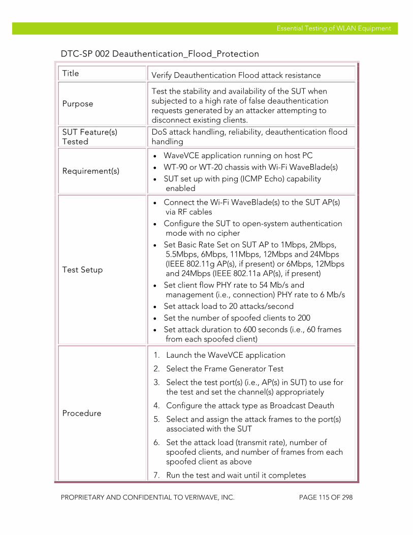
VeriWave, Inc. Essential Testing of WLAN Equipment
PROPRIETARY AND CONFIDENTIAL TO VERIWAVE, INC. PAGE 115 OF 298
Essential Testing of WLAN Equipment
DTC-SP 002 Deauthentication_Flood_Protection
Title Verify Deauthentication Flood attack resistance
Purpose
Test the stability and availability of the SUT when subjected to a high rate of false deauthentication requests generated by an attacker attempting to disconnect existing clients.
SUT Feature(s) Tested
DoS attack handling, reliability, deauthentication flood handling
Requirement(s)
• WaveVCE application running on host PC • WT-90 or WT-20 chassis with Wi-Fi WaveBlade(s) • SUT set up with ping (ICMP Echo) capability
enabled
Test Setup
• Connect the Wi-Fi WaveBlade(s) to the SUT AP(s) via RF cables
• Configure the SUT to open-system authentication mode with no cipher
• Set Basic Rate Set on SUT AP to 1Mbps, 2Mbps, 5.5Mbps, 6Mbps, 11Mbps, 12Mbps and 24Mbps (IEEE 802.11g AP(s), if present) or 6Mbps, 12Mbps and 24Mbps (IEEE 802.11a AP(s), if present)
• Set client flow PHY rate to 54 Mb/s and management (i.e., connection) PHY rate to 6 Mb/s
• Set attack load to 20 attacks/second • Set the number of spoofed clients to 200 • Set attack duration to 600 seconds (i.e., 60 frames
from each spoofed client)
Procedure
1. Launch the WaveVCE application
2. Select the Frame Generator Test
3. Select the test port(s) (i.e., AP(s) in SUT) to use for the test and set the channel(s) appropriately
4. Configure the attack type as Broadcast Deauth
5. Select and assign the attack frames to the port(s) associated with the SUT
6. Set the attack load (transmit rate), number of spoofed clients, and number of frames from each spoofed client as above
7. Run the test and wait until it completes

VeriWave, Inc. Essential Testing of WLAN Equipment
PROPRIETARY AND CONFIDENTIAL TO VERIWAVE, INC. PAGE 116 OF 298
Essential Testing of WLAN Equipment
8. Collect and examine the generated report
Test Priority High
Test Type DoS Attack
Pass/Fail Criteria
A Carrier Grade SUT should be able to withstand a DoS attack without adverse effects such as system crashes, and should be able to respond normally to authorized clients after the DoS attack ceases.
DTC-SP 003 Association_Flood_Protection
Title Verify Association Flood attack resistance
Purpose
Test the stability and availability of the SUT when subjected to a high rate of false association requests generated by an attacker spoofing many clients attempting to connect to a WLAN.
SUT Feature(s) Tested
DoS attack handling, reliability, association flood handling
Requirement(s)
• WaveVCE application running on host PC • WT-90 or WT-20 chassis with Wi-Fi WaveBlade(s) • SUT set up with ping (ICMP Echo) capability
enabled
Test Setup
• Connect the Wi-Fi WaveBlade(s) to the SUT AP(s) via RF cables
• Configure the SUT to open-system authentication mode with no cipher
• Set Basic Rate Set on SUT AP to 1Mbps, 2Mbps, 5.5Mbps, 6Mbps, 11Mbps, 12Mbps and 24Mbps (IEEE 802.11g AP(s), if present) or 6Mbps, 12Mbps and 24Mbps (IEEE 802.11a AP(s), if present)
• Set client flow PHY rate to 54 Mb/s and management (i.e., connection) PHY rate to 6 Mb/s
• Set attack load to 20 attacks/second • Set the number of spoofed clients to 200 • Set attack duration to 600 seconds (i.e., 60 frames
from each spoofed client)
Procedure 1. Launch the WaveVCE application
2. Select the Frame Generator Test

VeriWave, Inc. Essential Testing of WLAN Equipment
PROPRIETARY AND CONFIDENTIAL TO VERIWAVE, INC. PAGE 117 OF 298
Essential Testing of WLAN Equipment
3. Select the test port(s) (i.e., AP(s) in SUT) to use for the test and set the channel(s) appropriately
4. Configure the attack type as Association Flood
5. Select and assign the attack frames to the port(s) associated with the SUT
6. Set the attack load (transmit rate), number of spoofed clients, and number of frames from each spoofed client as above
7. Run the test and wait until it completes
8. Collect and examine the generated report
Test Priority High
Test Type DoS Attack
Pass/Fail Criteria
A Carrier Grade SUT should be able to withstand a DoS attack without adverse effects such as system crashes, and should be able to respond normally to authorized clients after the DoS attack ceases.
DTC-SP 004 Broadcast-Probe_Flood_Protection
Title Verify Broadcast Probe Flood attack resistance and recovery
Purpose
Test the stability and availability of the SUT when subjected to a high rate of false broadcast probe requests generated by an attacker spoofing many clients attempting to perform active scanning.
SUT Feature(s) Tested
DoS attack handling, reliability, broadcast probe flood handling
Requirement(s)
• WaveVCE application running on host PC • WT-90 or WT-20 chassis with Wi-Fi WaveBlade(s) • SUT set up with ping (ICMP Echo) capability
enabled
Test Setup
• Connect the Wi-Fi WaveBlade(s) to the SUT AP(s) via RF cables
• Configure the SUT to open-system authentication mode with no cipher
• Set Basic Rate Set on SUT AP to 1Mbps, 2Mbps, 5.5Mbps, 6Mbps, 11Mbps, 12Mbps and 24Mbps

VeriWave, Inc. Essential Testing of WLAN Equipment
PROPRIETARY AND CONFIDENTIAL TO VERIWAVE, INC. PAGE 118 OF 298
Essential Testing of WLAN Equipment
(IEEE 802.11g AP(s), if present) or 6Mbps, 12Mbps and 24Mbps (IEEE 802.11a AP(s), if present)
• Set client flow PHY rate to 54 Mb/s and management (i.e., connection) PHY rate to 6 Mb/s
• Set attack load to 20 attacks/second • Set the number of spoofed clients to 200 • Set attack duration to 600 seconds (i.e., 60 frames
from each spoofed client)
Procedure
1. Launch the WaveVCE application
2. Select the Frame Generator Test
3. Select the test port(s) (i.e., AP(s) in SUT) to use for the test and set the channel(s) appropriately
4. Configure the attack type as Broadcast Probe Flood
5. Select and assign the attack frames to the port(s) associated with the SUT
6. Set the attack load (transmit rate), number of spoofed clients, and number of frames from each spoofed client as above
7. Run the test and wait until it completes
8. Collect and examine the generated report
Test Priority High
Test Type DoS Attack
Pass/Fail Criteria
A Carrier Grade SUT should be able to withstand a DoS attack without adverse effects such as system crashes, and should be able to respond normally to authorized clients after the DoS attack ceases.
DTC-SP 005 Disassociation_Flood_Protection
Title Verify Disassociation Flood attack resistance
Purpose
Test the stability and availability of the SUT when subjected to a high rate of false disassociation requests generated by an attacker spoofing many clients attempting to disconnect.
SUT Feature(s) Tested
DoS attack handling, reliability, disassociation flood handling
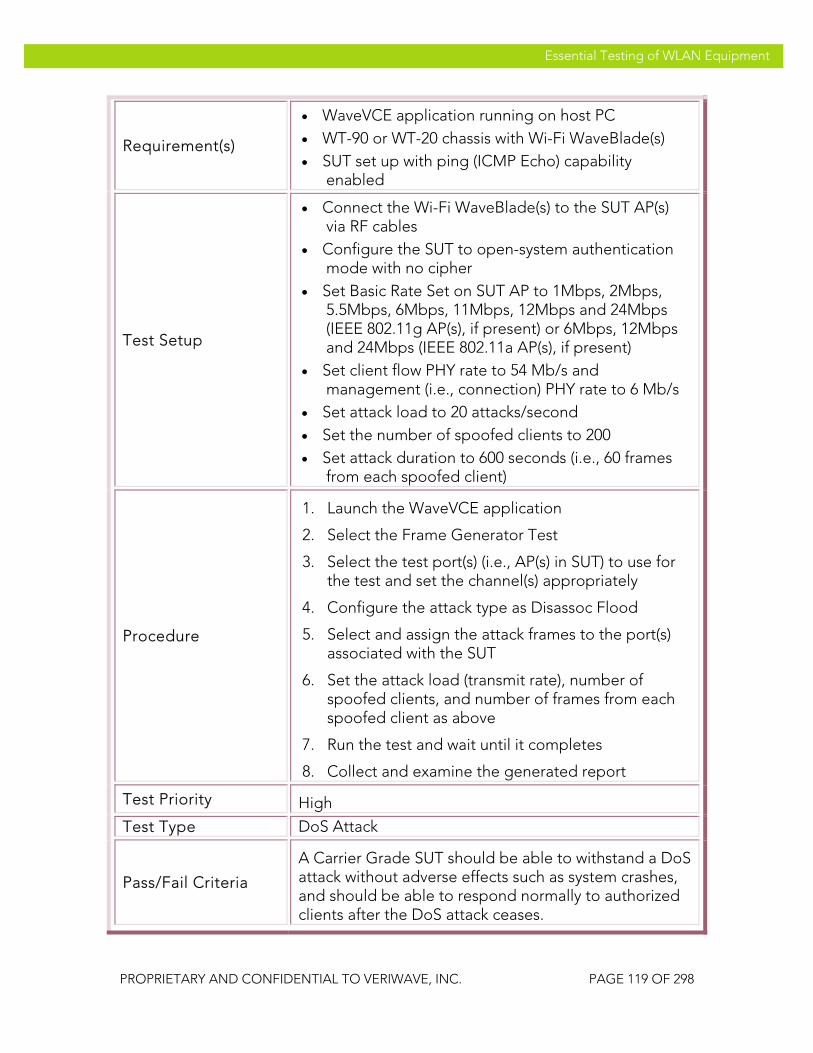
VeriWave, Inc. Essential Testing of WLAN Equipment
PROPRIETARY AND CONFIDENTIAL TO VERIWAVE, INC. PAGE 119 OF 298
Essential Testing of WLAN Equipment
Requirement(s)
• WaveVCE application running on host PC • WT-90 or WT-20 chassis with Wi-Fi WaveBlade(s) • SUT set up with ping (ICMP Echo) capability
enabled
Test Setup
• Connect the Wi-Fi WaveBlade(s) to the SUT AP(s) via RF cables
• Configure the SUT to open-system authentication mode with no cipher
• Set Basic Rate Set on SUT AP to 1Mbps, 2Mbps, 5.5Mbps, 6Mbps, 11Mbps, 12Mbps and 24Mbps (IEEE 802.11g AP(s), if present) or 6Mbps, 12Mbps and 24Mbps (IEEE 802.11a AP(s), if present)
• Set client flow PHY rate to 54 Mb/s and management (i.e., connection) PHY rate to 6 Mb/s
• Set attack load to 20 attacks/second • Set the number of spoofed clients to 200 • Set attack duration to 600 seconds (i.e., 60 frames
from each spoofed client)
Procedure
1. Launch the WaveVCE application
2. Select the Frame Generator Test
3. Select the test port(s) (i.e., AP(s) in SUT) to use for the test and set the channel(s) appropriately
4. Configure the attack type as Disassoc Flood
5. Select and assign the attack frames to the port(s) associated with the SUT
6. Set the attack load (transmit rate), number of spoofed clients, and number of frames from each spoofed client as above
7. Run the test and wait until it completes
8. Collect and examine the generated report
Test Priority High
Test Type DoS Attack
Pass/Fail Criteria
A Carrier Grade SUT should be able to withstand a DoS attack without adverse effects such as system crashes, and should be able to respond normally to authorized clients after the DoS attack ceases.

VeriWave, Inc. Essential Testing of WLAN Equipment
PROPRIETARY AND CONFIDENTIAL TO VERIWAVE, INC. PAGE 120 OF 298
Essential Testing of WLAN Equipment
DTC-SP 006 Reassociation-Request_Flood_Protection
Title Verify Reassociation Flood attack resistance
Purpose
Test the stability and availability of the SUT when subjected to a high rate of false disassociation requests generated by an attacker spoofing many clients attempting to move between APs.
SUT Feature(s) Tested
DoS attack handling, reliability, reassociation flood handling
Requirement(s)
• WaveVCE application running on host PC • WT-90 or WT-20 chassis with Wi-Fi WaveBlade(s) • SUT set up with ping (ICMP Echo) capability
enabled
Test Setup
• Connect the Wi-Fi WaveBlade(s) to the SUT AP(s) via RF cables
• Configure the SUT to open-system authentication mode with no cipher
• Set Basic Rate Set on SUT AP to 1Mbps, 2Mbps, 5.5Mbps, 6Mbps, 11Mbps, 12Mbps and 24Mbps (IEEE 802.11g AP(s), if present) or 6Mbps, 12Mbps and 24Mbps (IEEE 802.11a AP(s), if present)
• Set client flow PHY rate to 54 Mb/s and management (i.e., connection) PHY rate to 6 Mb/s
• Set attack load to 20 attacks/second • Set the number of spoofed clients to 200 • Set attack duration to 600 seconds (i.e., 60 frames
from each spoofed client)
Procedure
1. Launch the WaveVCE application
2. Select the Frame Generator Test
3. Select the test port(s) (i.e., AP(s) in SUT) to use for the test and set the channel(s) appropriately
4. Configure the attack type as Reassoc Flood
5. Select and assign the attack frames to the port(s) associated with the SUT
6. Set the attack load (transmit rate), number of spoofed clients, and number of frames from each spoofed client as above
7. Run the test and wait until it completes
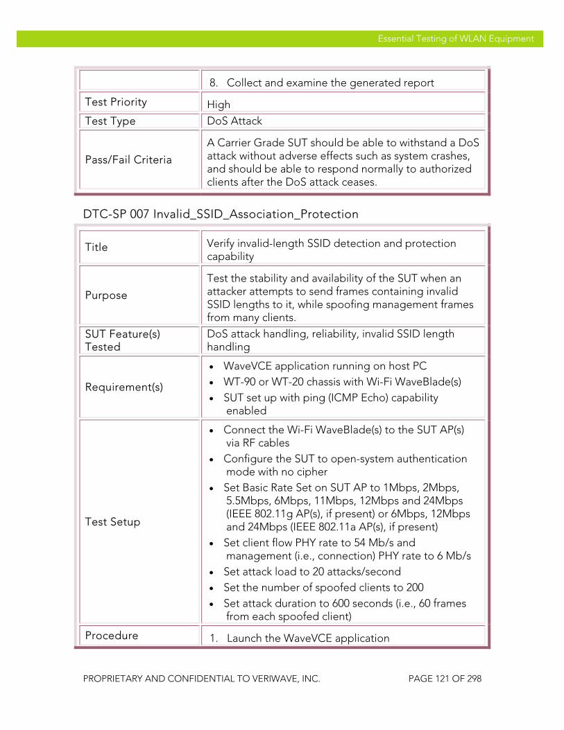
VeriWave, Inc. Essential Testing of WLAN Equipment
PROPRIETARY AND CONFIDENTIAL TO VERIWAVE, INC. PAGE 121 OF 298
Essential Testing of WLAN Equipment
8. Collect and examine the generated report
Test Priority High
Test Type DoS Attack
Pass/Fail Criteria
A Carrier Grade SUT should be able to withstand a DoS attack without adverse effects such as system crashes, and should be able to respond normally to authorized clients after the DoS attack ceases.
DTC-SP 007 Invalid_SSID_Association_Protection
Title Verify invalid-length SSID detection and protection capability
Purpose
Test the stability and availability of the SUT when an attacker attempts to send frames containing invalid SSID lengths to it, while spoofing management frames from many clients.
SUT Feature(s) Tested
DoS attack handling, reliability, invalid SSID length handling
Requirement(s)
• WaveVCE application running on host PC • WT-90 or WT-20 chassis with Wi-Fi WaveBlade(s) • SUT set up with ping (ICMP Echo) capability
enabled
Test Setup
• Connect the Wi-Fi WaveBlade(s) to the SUT AP(s) via RF cables
• Configure the SUT to open-system authentication mode with no cipher
• Set Basic Rate Set on SUT AP to 1Mbps, 2Mbps, 5.5Mbps, 6Mbps, 11Mbps, 12Mbps and 24Mbps (IEEE 802.11g AP(s), if present) or 6Mbps, 12Mbps and 24Mbps (IEEE 802.11a AP(s), if present)
• Set client flow PHY rate to 54 Mb/s and management (i.e., connection) PHY rate to 6 Mb/s
• Set attack load to 20 attacks/second • Set the number of spoofed clients to 200 • Set attack duration to 600 seconds (i.e., 60 frames
from each spoofed client)
Procedure 1. Launch the WaveVCE application
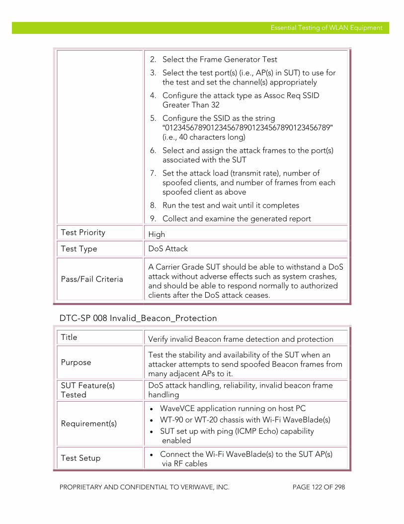
VeriWave, Inc. Essential Testing of WLAN Equipment
PROPRIETARY AND CONFIDENTIAL TO VERIWAVE, INC. PAGE 122 OF 298
Essential Testing of WLAN Equipment
2. Select the Frame Generator Test
3. Select the test port(s) (i.e., AP(s) in SUT) to use for the test and set the channel(s) appropriately
4. Configure the attack type as Assoc Req SSID Greater Than 32
5. Configure the SSID as the string “0123456789012345678901234567890123456789” (i.e., 40 characters long)
6. Select and assign the attack frames to the port(s) associated with the SUT
7. Set the attack load (transmit rate), number of spoofed clients, and number of frames from each spoofed client as above
8. Run the test and wait until it completes
9. Collect and examine the generated report
Test Priority High
Test Type DoS Attack
Pass/Fail Criteria
A Carrier Grade SUT should be able to withstand a DoS attack without adverse effects such as system crashes, and should be able to respond normally to authorized clients after the DoS attack ceases.
DTC-SP 008 Invalid_Beacon_Protection
Title Verify invalid Beacon frame detection and protection
Purpose Test the stability and availability of the SUT when an attacker attempts to send spoofed Beacon frames from many adjacent APs to it.
SUT Feature(s) Tested
DoS attack handling, reliability, invalid beacon frame handling
Requirement(s)
• WaveVCE application running on host PC • WT-90 or WT-20 chassis with Wi-Fi WaveBlade(s) • SUT set up with ping (ICMP Echo) capability
enabled
Test Setup • Connect the Wi-Fi WaveBlade(s) to the SUT AP(s) via RF cables
VeriWave, Inc. Essential Testing of WLAN Equipment
PROPRIETARY AND CONFIDENTIAL TO VERIWAVE, INC. PAGE 123 OF 298
Essential Testing of WLAN Equipment
• Configure the SUT to open-system authentication mode with no cipher
• Set Basic Rate Set on SUT AP to 1Mbps, 2Mbps, 5.5Mbps, 6Mbps, 11Mbps, 12Mbps and 24Mbps (IEEE 802.11g AP(s), if present) or 6Mbps, 12Mbps and 24Mbps (IEEE 802.11a AP(s), if present)
• Set client flow PHY rate to 54 Mb/s and management (i.e., connection) PHY rate to 6 Mb/s
• Set attack load to 20 attacks/second • Set the number of spoofed clients (i.e., neighbor
APs) to 200 • Set attack duration to 600 seconds (i.e., 60 frames
from each spoofed AP)
Procedure
1. Launch the WaveVCE application
2. Select the Frame Generator Test
3. Select the test port(s) (i.e., AP(s) in SUT) to use for the test and set the channel(s) appropriately
4. Configure the attack type as Invalid Beacons
5. Select and assign the attack frames to the port(s) associated with the SUT
6. Set the attack load (transmit rate), number of spoofed clients, and number of frames from each spoofed client as above
7. Run the test and wait until it completes
8. Collect and examine the generated report
Test Priority High
Test Type DoS Attack
Pass/Fail Criteria
A Carrier Grade SUT should be able to withstand a DoS attack without adverse effects such as system crashes, and should be able to respond normally to authorized clients after the DoS attack ceases.
DTC-SP 009 Invalid_Power-Save-Poll_Protection
Title Verify Invalid Power-Save Poll frame detection and protection

VeriWave, Inc. Essential Testing of WLAN Equipment
PROPRIETARY AND CONFIDENTIAL TO VERIWAVE, INC. PAGE 124 OF 298
Essential Testing of WLAN Equipment
Purpose Test the stability and availability of the SUT when an attacker attempts to send invalid Power-Save Poll (PS-Poll) frames from many spoofed clients to it.
SUT Feature(s) Tested
DoS attack handling, reliability, invalid PS-Poll frame handling
Requirement(s)
• WaveVCE application running on host PC • WT-90 or WT-20 chassis with Wi-Fi WaveBlade(s) • SUT set up with ping (ICMP Echo) capability
enabled
Test Setup
• Connect the Wi-Fi WaveBlade(s) to the SUT AP(s) via RF cables
• Configure the SUT to open-system authentication mode with no cipher
• Set Basic Rate Set on SUT AP to 1Mbps, 2Mbps, 5.5Mbps, 6Mbps, 11Mbps, 12Mbps and 24Mbps (IEEE 802.11g AP(s), if present) or 6Mbps, 12Mbps and 24Mbps (IEEE 802.11a AP(s), if present)
• Set client flow PHY rate to 54 Mb/s and management (i.e., connection) PHY rate to 6 Mb/s
• Set attack load to 20 attacks/second • Set the number of spoofed clients to 200 • Set attack duration to 600 seconds (i.e., 60 frames
from each spoofed client)
Procedure
1. Launch the WaveVCE application
2. Select the Frame Generator Test
3. Select the test port(s) (i.e., AP(s) in SUT) to use for the test and set the channel(s) appropriately
4. Configure the attack type as Invalid PS-Poll
5. Select and assign the attack frames to the port(s) associated with the SUT
6. Set the attack load (transmit rate), number of spoofed clients, and number of frames from each spoofed client as above
7. Run the test and wait until it completes
8. Collect and examine the generated report
Test Priority High

VeriWave, Inc. Essential Testing of WLAN Equipment
PROPRIETARY AND CONFIDENTIAL TO VERIWAVE, INC. PAGE 125 OF 298
Essential Testing of WLAN Equipment
Test Type DoS Attack
Pass/Fail Criteria
A Carrier Grade SUT should be able to withstand a DoS attack without adverse effects such as system crashes, and should be able to respond normally to authorized clients after the DoS attack ceases.
DTC-SP 010 Bad_Data-Frame_Protection
Title Verify Bad Data frame detection and protection
Purpose
Test the stability and availability of the SUT when an attacker attempts to send invalid data frames from many spoofed clients to it. In this context, invalid data frames are those with illegal header contents or invalid header formats.
SUT Feature(s) Tested
DoS attack handling, reliability, invalid data frame handling
Requirement(s)
• WaveVCE application running on host PC • WT-90 or WT-20 chassis with Wi-Fi WaveBlade(s) • SUT set up with ping (ICMP Echo) capability
enabled
Test Setup
• Connect the Wi-Fi WaveBlade(s) to the SUT AP(s) via RF cables
• Configure the SUT to open-system authentication mode with no cipher
• Set Basic Rate Set on SUT AP to 1Mbps, 2Mbps, 5.5Mbps, 6Mbps, 11Mbps, 12Mbps and 24Mbps (IEEE 802.11g AP(s), if present) or 6Mbps, 12Mbps and 24Mbps (IEEE 802.11a AP(s), if present)
• Set client flow PHY rate to 54 Mb/s and management (i.e., connection) PHY rate to 6 Mb/s
• Set attack load to 20 attacks/second • Set the number of spoofed clients to 200 • Set attack duration to 600 seconds (i.e., 60 frames
from each spoofed client)
Procedure
1. Launch the WaveVCE application
2. Select the Frame Generator Test
3. Select the test port(s) (i.e., AP(s) in SUT) to use for the test and set the channel(s) appropriately

VeriWave, Inc. Essential Testing of WLAN Equipment
PROPRIETARY AND CONFIDENTIAL TO VERIWAVE, INC. PAGE 126 OF 298
Essential Testing of WLAN Equipment
4. Configure the attack type as Invalid Data Frame
5. Select and assign the attack frames to the port(s) associated with the SUT
6. Set the attack load (transmit rate), number of spoofed clients, and number of frames from each spoofed client as above
7. Run the test and wait until it completes
8. Collect and examine the generated report
Test Priority High
Test Type DoS Attack
Pass/Fail Criteria
A Carrier Grade SUT should be able to withstand a DoS attack without adverse effects such as system crashes, and should be able to respond normally to authorized clients after the DoS attack ceases.
Performance and Capacity Benchmarks This section covers test cases that are essential to quantifying the performance and capacity of the SUT. Test case results either indicate that the specific performance metric is at, above or below acceptable performance levels. Better than acceptable performance and capacity levels is good indicator that the SUT is capable of operating effectively in actual deployment conditions.
Capacity and Coverage Benchmarking It is critical for network design engineers to know the capacity of the network that they’re deploying. Understanding the maximum client capacity of the SUT as well as the area coverage offered by the APs will provide an indication of how dense each AP cell can be allowed to grow, and hence determine the number of APs needed to provide sufficient coverage and capacity for any deployment. Knowing the VoIP capacity of the network will help traffic planning to determine not only the maximum number of calls that can be supported while maintaining sufficient voice quality but also the maximum data traffic that can be allowed while operating these high-quality voice calls.
Client/Call Capacity
The client capacity and VoIP call capacity tests determine the maximum number of mobile clients or handsets that can feasibly be supported by the SUT. Note that this is quite different from the datasheet specifications of association database size. In order to successfully support a client or handset, the SUT must not merely associate (register) it, but also needs to support the client’s minimum

VeriWave, Inc. Essential Testing of WLAN Equipment
PROPRIETARY AND CONFIDENTIAL TO VERIWAVE, INC. PAGE 127 OF 298
Essential Testing of WLAN Equipment
data transfer requirements. Failure to support a minimum level of requirements creates situations where users can easily connect to the WLAN but their applications fail to work well (or time out entirely), leading to serious issues with the user experience.
The capacity tests therefore present the SUT with an increasing number of clients (data or VoIP, depending on the specific test). After connection, each client attempts to transfer a predetermined amount of data per second, or establish a VoIP call with a specified minimum quality level. A threshold is set on the data transfer performance. If the SUT fails to sustain the desired level of data performance, the test tries a lower number of clients; otherwise, the test tries a higher number of clients. The test ends when the maximum number of clients have been connected consistent with the predetermined performance threshold.
The tests are conducted with different options to explore the SUT capacity in different dimensions.
CBTC-SP 001 Max_Client_Capacity_DHCP
Title Assess maximum client capacity with DHCP active
Purpose
Measure the maximum number of DHCP-based wireless clients that can be supported by the SUT with each client being able to transfer a pre-set minimum amount of data per second. Note that the capabilities of the DHCP server are included in those of the SUT.
SUT Feature(s) Tested
Client database capacity, security context capacity, queuing and buffer allocation limits, DHCP capacity
Requirement(s)
• WaveApps application running on host PC • WT-90 or WT-20 chassis with Wi-Fi WaveBlade(s)
and Ethernet WaveBlade(s) • SUT set up to support UDP traffic • DHCP enabled, with a DHCP server present and
serving a sufficient number of IP addresses
Test Setup
• Configure the SUT with security modes to: Open, WEP-128, WPA-PSK, WPA2-PSK
• Configure DHCP in the SUT and related network • Set Basic Rate Set on SUT to 1Mbps, 2Mbps,
5.5Mbps, 6Mbps, 11Mbps, 12Mbps and 24Mbps (IEEE 802.11g mode APs) and/or 6Mbps, 12Mbps and 24Mbps (IEEE 802.11a mode APs)
• Set client PHY rate to 54 Mb/s
• Run test with no cipher, WEP-128, TKIP (WPA) and AES-CCMP (WPA2) encryption

VeriWave, Inc. Essential Testing of WLAN Equipment
PROPRIETARY AND CONFIDENTIAL TO VERIWAVE, INC. PAGE 128 OF 298
Essential Testing of WLAN Equipment
Procedure
1. Launch the WaveApps application
2. Select the Client Capacity Test under the IEEE Benchmark Test suite
3. Select the test port(s) (i.e., APs) to use for the test and configure each port into IEEE 802.11g or IEEE 802.11a mode as required
4. Create an Ethernet client group on the correct port(s) with the number of Ethernet clients set to 1, using static IP
5. Create WLAN client group(s) as required to fill 150% of the expected client capacity of the SUT
6. Select the SSID(s) for the WLAN clients and configure the clients to obtain their IP addresses via DHCP
7. Configure an initial wireless client security mode of Open (no security or encryption) for all clients
8. Select UDP as the traffic type
9. Set the frame size to 512 bytes and the ILOAD per client to 10 frames per second (~41 kb/s per client); set the search maximum to the total number of clients created in step 5
10. Run the test and wait until it completes
11. Examine and record the results
12. Repeat steps 8 to 11 with WEP-128, WPA-PSK, WPA2-PSK security modes
Test Priority Mandatory
Test Type Client Capacity
Pass/Fail Criteria
A Carrier Grade SUT should support at least 100 DHCP-based clients per AP, and be capable of transferring data to every connected client at a sustained rate of at least 40 kb/s.

VeriWave, Inc. Essential Testing of WLAN Equipment
PROPRIETARY AND CONFIDENTIAL TO VERIWAVE, INC. PAGE 129 OF 298
Essential Testing of WLAN Equipment
CBTC-SP 002 Max_VoIP_Call_Capacity_DHCP
Title Assess maximum voice call capacity in presence of data with DHCP active
Purpose
Measure the maximum number of voice calls that can be supported by the SUT in the presence of a fixed amount of best-efforts data traffic without degrading call quality below a pre-set service level agreement (SLA) threshold. Different codec types are used to determine the impact of the codec on the call capacity. The SLA is expressed in terms of an objective voice quality measure (R-value). DHCP is used to supply IP addresses.
SUT Feature(s) Tested
Maximum number of voice calls, voice/data prioritization capabilities, QoS implementation efficacy, packet inspection capacity, DHCP capacity
Requirement(s)
• WaveApps application running on host PC • WT-90 or WT-20 chassis with Wi-Fi WaveBlade(s)
and Ethernet WaveBlade(s)
• SUT set up to support 2 (or more) QoS levels and UDP traffic
• DHCP enabled, with a DHCP server present and serving a sufficient number of IP addresses
Test Setup
• Configure the SUT with security modes to: Open, WEP-128, WPA-PSK, WPA2-PSK
• Configure DHCP in the SUT and related network • Set Basic Rate Set on SUT APs to 1Mbps, 2Mbps,
5.5Mbps, 6Mbps, 11Mbps, 12Mbps and 24Mbps (IEEE 802.11g APs, if present) or 6Mbps, 12Mbps and 24Mbps (IEEE 802.11a APs, if present)
• Enable WMM/802.11e and 802.1Q prioritization on the SUT with the number of QoS classes being at least 2 (Best Efforts and Voice); each WMM/802.11e AC should correspond to a different SSID configured on the SUT
• Set the SLA for the test as: minimum R-value of 78 • Run test with no cipher, WEP-128, TKIP (WPA), and
AES-CCMP (WPA2) • Run test with Best Efforts TCP traffic frame sizes: 88,
128, 256, 512, 1024 and 1518 bytes

VeriWave, Inc. Essential Testing of WLAN Equipment
PROPRIETARY AND CONFIDENTIAL TO VERIWAVE, INC. PAGE 130 OF 298
Essential Testing of WLAN Equipment
• Run test with background traffic rates of: 10, 50, 100 and 500 frames/second per AP
• Run test with G.711, G.723 and G.729 voice codec types
Procedure
1. Launch the WaveApps application
2. Select the Service Capacity Test under the VoIP QoS test suite
3. Select the test port(s) (i.e., APs) to use for the test
4. Select SSID and configure WLAN clients to obtain their IP addresses via DHCP
5. Create an Ethernet client group on the correct port(s) with the number of Ethernet clients set to 1, and obtaining IP addresses via DHCP
6. Set the voice call traffic for WLAN QoS with user priority 6 and the background traffic for WLAN QoS with user priority 0
7. Set the other traffic QoS settings (TOS, DSCP, port numbers) to match the SUT requirements, and set the SLA threshold to an R-value of 78
8. Set the initial Wi-Fi security mode to open (no security)
9. Select the initial background traffic frame size as 88 bytes, TCP traffic type
10. Set the initial codec type to G.711
11. Set the initial background traffic rate to 10 frames/second per AP
12. Run the test
13. Wait until test completes
14. Collect report and results data
15. Repeat steps 12 to 14 with 50, 100 and 500 frames/second of background data traffic per AP
16. Repeat steps 11 to 15 with G.723 and G.729 codec types
17. Repeat steps 10 to 16 with frame sizes 128, 256, 512, 1024 and 1518 bytes
18. Repeat steps 9 to 17 with WEP-128, WPA-PSK,

VeriWave, Inc. Essential Testing of WLAN Equipment
PROPRIETARY AND CONFIDENTIAL TO VERIWAVE, INC. PAGE 131 OF 298
Essential Testing of WLAN Equipment
WPA2-PSK security modes
Test Priority Mandatory
Test Type Client Capacity
Pass/Fail Criteria
A Carrier Grade SUT should support at least 30 voice calls, irrespective of codec type, with an average R-value greater than 78 at the specified background traffic loading
CBTC-SP 003 Max_Mesh_Client_Capacity_DHCP
Title Assess maximum client capacity of a WLAN mesh with DHCP active
Purpose
Measure the maximum number of wireless clients that can be supported by a WLAN mesh SUT with each client being able to transfer a pre-set minimum amount of data per second. DHCP is active and used to provide IP addresses. Note that the client capacity of a mesh may be affected by the mesh topology.
SUT Feature(s) Tested
Client database capacity, security context capacity, queuing and buffer allocation limits, mesh algorithm efficiency, mesh DHCP capacity
Requirement(s)
• WaveApps application running on host PC • WT-90 or WT-20 chassis with Wi-Fi WaveBlade(s)
and Ethernet WaveBlade(s) • SUT set up to support UDP traffic • DHCP disabled with a DHCP server present and
serving a sufficient number of IP addresses
Test Setup
• Configure the mesh SUT with security modes to: Open, WEP-128, WPA-PSK, WPA2-PSK
• Configure DHCP in the SUT and related network • Set Basic Rate Set on SUT to 1Mbps, 2Mbps,
5.5Mbps, 6Mbps, 11Mbps, 12Mbps and 24Mbps (assuming IEEE 802.11g mode access links)
• Set client PHY rate to 54 Mb/s • Run test with no cipher, WEP-128, TKIP (WPA) and
AES-CCMP (WPA2) encryption
Procedure TBD
Test Priority Low

VeriWave, Inc. Essential Testing of WLAN Equipment
PROPRIETARY AND CONFIDENTIAL TO VERIWAVE, INC. PAGE 132 OF 298
Essential Testing of WLAN Equipment
Test Type Client Capacity
Pass/Fail Criteria
A Carrier Grade SUT should support at least 100 clients per mesh AP, and be capable of transferring data to every connected client at a sustained rate of at least 40 kb/s.
CBTC-SP 004 Max_Mesh_VoIP_Call_Capacity_DHCP
Title Assess maximum voice call capacity in presence of data for a mesh system with DHCP active
Purpose
Measure the maximum number of voice calls that can be supported by a mesh SUT in the presence of a fixed amount of best-efforts data traffic without degrading call quality below a pre-set service level agreement (SLA) threshold. Different codec types are used to determine the impact of the codec on the call capacity. The SLA is expressed in terms of an objective voice quality measure (R-value). DHCP is used to supply IP addresses. This test is only applicable to SUTs configured as a WLAN mesh.
SUT Feature(s) Tested
Maximum number of voice calls, voice/data prioritization capabilities, QoS implementation efficacy, packet inspection capacity, mesh algorithm efficiency, DHCP capacity
Requirement(s)
• WaveApps application running on host PC • WT-90 or WT-20 chassis with Wi-Fi WaveBlade(s)
and Ethernet WaveBlade(s) • Mesh SUT set up to support 2 (or more) QoS levels
and UDP traffic • DHCP enabled, with a DHCP server present and
serving a sufficient number of IP addresses
Test Setup
• Configure the SUT with security modes to: Open, WEP-128, WPA-PSK, WPA2-PSK
• Configure DHCP in the SUT and related network • Set Basic Rate Set on SUT to 1Mbps, 2Mbps,
5.5Mbps, 6Mbps, 11Mbps, 12Mbps and 24Mbps (assuming IEEE 802.11g mode access links)
• Enable WMM/802.11e and 802.1Q prioritization on the mesh SUT with the number of QoS classes being at least 2 (Best Efforts and Voice); each

VeriWave, Inc. Essential Testing of WLAN Equipment
PROPRIETARY AND CONFIDENTIAL TO VERIWAVE, INC. PAGE 133 OF 298
Essential Testing of WLAN Equipment
WMM/802.11e AC should correspond to a different SSID configured on the SUT
• Set the SLA for the test as: minimum R-value of 78 • Run test with no cipher, WEP-128, TKIP (WPA), and
AES-CCMP (WPA2) • Run test with Best Efforts TCP traffic frame sizes: 88,
128, 256, 512, 1024 and 1518 bytes • Run test with background traffic rates of: 10, 50, 100
and 500 frames/second per AP • Run test with G.711, G.723 and G.729 voice codec
types
Procedure TBD
Test Priority Low
Test Type Client Capacity
Pass/Fail Criteria
A Carrier Grade mesh SUT should support at least 10 voice calls per AP in the SUT, irrespective of codec type, with an average R-value greater than 78 at the specified background traffic loading
Rate vs. Range
The Rate vs. Range tests measure the variation in the forwarded traffic rate through the SUT as a function of path loss (which in turn is a function of the range, or the distance between AP and client). Increasing range is simulated by reducing the transmit power and increasing the perceived frame error ratio; this matches what is seen by the SUT when client stations move away from it. The forwarding rate at the specified offered load is measured while range effects are being increased. These tests characterize the ability of the SUT to cover a large area in an actual deployment. A higher value for range at a specified rate indicates a SUT that can cover a larger area without losing network capacity. Alternatively, the tests can be used to determine the offered capacity of the SUT in a fixed coverage region. In addition, the tests exercise the rate adaptation algorithm used by the SUT to maximize transfer efficiency as the client moves further away. These tests are hence crucial for determining the coverage area of service provider APs, and therefore the cost and time required to build out a WLAN. For the Rate vs. Range tests, the SUT must be directly connected (via RF cables) to the WLAN WaveBlade, and external attenuation (typically around 70dB) must be placed in the RF path. This is done to ensure that the received power level at the WLAN WaveBlade is between -45 to -55 dBm.

VeriWave, Inc. Essential Testing of WLAN Equipment
PROPRIETARY AND CONFIDENTIAL TO VERIWAVE, INC. PAGE 134 OF 298
Essential Testing of WLAN Equipment
CBTC-SP 010 Rate_vs_Range_80211b
Title Measure Rate vs. Range in IEEE 802.11b mode
Purpose Measures the forwarding rate sustained by the SUT as a function of path loss while the SUT is operating in IEEE 802.11b-only mode
SUT Feature(s) Tested
SUT coverage area, SUT rate adaptation capability
Requirement(s)
• WaveApps application running on host PC • WT-90 or WT-20 chassis with Wi-Fi WaveBlade(s)
and Ethernet WaveBlade(s) • SUT set up to support UDP traffic • DHCP enabled • External attenuation in RF path (typically 70dB)
Test Setup
• Configure the SUT with open authentication • Set Basic Rate Set on SUT to 1Mbps, 2Mbps,
5.5Mbps, 11Mbps • Set client PHY rate to 11 Mb/s in IEEE 802.11b-only
mode • Run test with no security (open authentication, no
encryption) • Run test with UDP frame sizes: 88, 128, 256, 512,
1024, 1280 and 1518 bytes • Add external attenuation between antenna port
and AP so RSSI power at the station is between -45 and -55 dBm; typically 70 dB of attenuation is needed
Procedure
1. Launch the WaveApps application
2. Select the Rate vs. Range Test under the IEEE 802.11.2 Benchmark Test Suite
3. Select the test port (i.e., AP) to use for the test
4. Select SSID and configure the clients to open authentication with no encryption and obtain IP addresses via DHCP
5. Create an Ethernet client group on the correct port with the number of Ethernet clients set to 1
6. Set the number of Wi-Fi clients to 1
7. Select frame sizes of 88, 128, 256, 512, 1024, 1280
VeriWave, Inc. Essential Testing of WLAN Equipment
PROPRIETARY AND CONFIDENTIAL TO VERIWAVE, INC. PAGE 135 OF 298
Essential Testing of WLAN Equipment
and 1518 bytes and UDP traffic type
8. Enter the amount of external attenuation
9. Run the test
10. Wait until test completes
11. Collect report and results data
Test Priority Mandatory
Test Type Performance
Pass/Fail Criteria
There are no pass/fail criteria for this test. Maintenance of a high data forwarding rate for a longer period (i.e., a higher degree of path loss) indicates a more capable SUT. The rate vs. range (path loss) graph should not show any discontinuities or irregularities that denote instabilities in the rate management algorithms.
CBTC-SP 011 Rate_vs_Range_80211g
Title Measure Rate vs. Range in IEEE 802.11g mode
Purpose Measures the forwarding rate sustained by the SUT as a function of path loss while the SUT is operating in IEEE 802.11g-only mode
SUT Feature(s) Tested
SUT coverage area, SUT rate adaptation capability
Requirement(s)
• WaveApps application running on host PC • WT-90 or WT-20 chassis with Wi-Fi WaveBlade(s)
and Ethernet WaveBlade(s) • SUT set up to support UDP traffic • DHCP enabled • External attenuation in RF path (typically 70dB)
Test Setup
• Configure the SUT with open authentication • Set Basic Rate Set on SUT to 6 Mbps, 12 Mbps, 24
Mbps • Set client PHY rate to 54 Mb/s in IEEE 802.11g-only
mode • Run test with no security (open authentication, no
encryption) • Run test with UDP frame sizes: 88, 128, 256, 512,
1024, 1280 and 1518 bytes

VeriWave, Inc. Essential Testing of WLAN Equipment
PROPRIETARY AND CONFIDENTIAL TO VERIWAVE, INC. PAGE 136 OF 298
Essential Testing of WLAN Equipment
• Add external attenuation between antenna port and AP so RSSI power at the station is between -45 and -55 dBm; typically 70 dB of attenuation is needed
Procedure
1. Launch the WaveApps application
2. Select the Rate vs. Range Test under the IEEE 802.11.2 Benchmark Test Suite
3. Select the test port (i.e., AP) to use for the test
4. Select SSID and configure the clients to open authentication with no encryption and obtain IP addresses via DHCP
5. Create an Ethernet client group on the correct port with the number of Ethernet clients set to 1
6. Set the number of Wi-Fi clients to 1
7. Select frame sizes of 88, 128, 256, 512, 1024, 1280 and 1518 bytes and UDP traffic type
8. Enter the amount of external attenuation
9. Run the test
10. Wait until test completes
11. Collect report and results data
Test Priority Mandatory
Test Type Performance
Pass/Fail Criteria
There are no pass/fail criteria for this test. Maintenance of a high data forwarding rate for a longer period (i.e., a higher degree of path loss) indicates a more capable SUT. The rate vs. range (path loss) graph should not show any discontinuities or irregularities that denote instabilities in the rate management algorithms.
CBTC-SP 012 Rate_vs_Range_80211a
Title Measure Rate vs. Range in IEEE 802.11a mode
Purpose
Measures the forwarding rate sustained by the SUT as a function of path loss while the SUT is operating in IEEE 802.11a mode. This test is only applicable to SUTs that support IEEE 802.11a.
VeriWave, Inc. Essential Testing of WLAN Equipment
PROPRIETARY AND CONFIDENTIAL TO VERIWAVE, INC. PAGE 137 OF 298
Essential Testing of WLAN Equipment
SUT Feature(s) Tested
SUT coverage area, SUT rate adaptation capability
Requirement(s)
• WaveApps application running on host PC • WT-90 or WT-20 chassis with Wi-Fi WaveBlade(s)
and Ethernet WaveBlade(s) • SUT set up to support UDP traffic • DHCP enabled • External attenuation in RF path (typically 70dB)
Test Setup
• Configure the SUT with open authentication • Set Basic Rate Set on SUT to 6 Mbps, 12 Mbps, 24
Mbps • Set client PHY rate to 54 Mb/s in IEEE 802.11g-only
mode • Run test with no security (open authentication, no
encryption) • Run test with UDP frame sizes: 88, 128, 256, 512,
1024, 1280 and 1518 bytes • Add external attenuation between antenna port
and AP so RSSI power at the station is between -45 and -55 dBm; typically 70 dB of attenuation is needed
Procedure
1. Launch the WaveApps application
2. Select the Rate vs. Range Test under the IEEE 802.11.2 Benchmark Test Suite
3. Select the test port (i.e., AP) to use for the test
4. Select SSID and configure the clients to open authentication with no encryption and obtain IP addresses via DHCP
5. Create an Ethernet client group on the correct port with the number of Ethernet clients set to 1
6. Set the number of Wi-Fi clients to 1
7. Select frame sizes of 88, 128, 256, 512, 1024, 1280 and 1518 bytes and UDP traffic type
8. Enter the amount of external attenuation
9. Run the test
10. Wait until test completes
11. Collect report and results data

VeriWave, Inc. Essential Testing of WLAN Equipment
PROPRIETARY AND CONFIDENTIAL TO VERIWAVE, INC. PAGE 138 OF 298
Essential Testing of WLAN Equipment
Test Priority Mandatory
Test Type Performance
Pass/Fail Criteria
There are no pass/fail criteria for this test. Maintenance of a high data forwarding rate for a longer period (i.e., a higher degree of path loss) indicates a more capable SUT. The rate vs. range (path loss) graph should not show any discontinuities or irregularities that denote instabilities in the rate management algorithms.
Performance Benchmarking
For a WLAN to be able to scale and successfully support various applications running a variety of traffic types and sizes it has to maintain a high throughput, low packet loss, and minimal latency/jitter on both non-encrypted and encrypted networks. It is critical to drive WLAN traffic at link capacity while also scaling-up the number of clients to make these performance measurements. In addition to that the WLAN needs to meet stringent mobility requirements in terms of minimal roaming delays while supporting complex security types and roaming patterns.
Throughput
The following throughput tests measure the maximum rate which the SUT can forward packets without packet loss. Throughput tests are a key measurement of the performance of the SUT and will help determine how much traffic and how many users the SUT can support. Also, unexpected levels of packet loss detected during throughput tests can be indicative of internal issues with the SUT.
The throughput tests are conducted with a variety of frame sizes, numbers of clients, and directions (i.e., upstream, downstream and bi-directional). They are also carried out with different traffic types (i.e., UDP and TCP).
PBTC-SP 001 Upstream_UDP_80211g_Throughput
Title Measure upstream UDP IEEE 802.11g throughput
Purpose Measure the upstream UDP throughput that can be achieved on the SUT operating in IEEE 802.11g mode
SUT Feature(s) Tested
Maximum reliable data forwarding capacity, basic performance
Requirement(s) • WaveApps application running on host PC • WT-90 or WT-20 chassis with Wi-Fi WaveBlade(s)
and Ethernet WaveBlade(s)

VeriWave, Inc. Essential Testing of WLAN Equipment
PROPRIETARY AND CONFIDENTIAL TO VERIWAVE, INC. PAGE 139 OF 298
Essential Testing of WLAN Equipment
• SUT set up to support UDP traffic • DHCP enabled
Test Setup
• Configure the SUT to open-system authentication mode
• Set Basic Rate Set on SUT to 1Mbps, 2Mbps, 5.5Mbps, 6Mbps, 11Mbps, 12Mbps, 24Mbps
• Set client PHY rate to 54 Mb/s in IEEE 802.11g-only mode
• Run test with no encryption, TKIP and AES-CCMP • Run test with UDP frame sizes: 88, 128, 256, 512,
1024, 1280 and 1518 bytes • Run test with 1, 10, 20 and 100 clients per AP; for a
WLAN controller-based system, at least one test must be run with >1000 clients
Procedure
1. Launch the WaveApps application
2. Select the Throughput Test under the IEEE 802.11.2 Benchmark Test Suite
3. Select the test port(s) (i.e., APs) to use for the test
4. Select SSID and configure the clients to open authentication with no encryption and obtain IP addresses via DHCP
5. Create an Ethernet client group on the correct port(s) with the initial number of Ethernet clients set to 1 per AP
6. Set the initial number of Wi-Fi clients to 1 per AP
7. Select frame sizes of 88, 128, 256, 512, 1024, 1280 and 1518 bytes and UDP traffic type
8. Select Wireless to Ethernet (one-to-one, upstream) mapping
9. Run the test
10. Wait until test completes
11. Collect report and results data
12. Repeat steps 5 to 11 with 10, 20, and 100 clients per AP configured on both Ethernet and Wi-Fi sides (one-to-one)
13. Repeat steps 5 to 12 with WPA-TKIP and WPA2-AES encryption modes

VeriWave, Inc. Essential Testing of WLAN Equipment
PROPRIETARY AND CONFIDENTIAL TO VERIWAVE, INC. PAGE 140 OF 298
Essential Testing of WLAN Equipment
Test Priority Mandatory
Test Type Performance
Pass/Fail Criteria
A Carrier Grade SUT should achieve the following upstream throughput: >= 30 Mbps for 1518 byte frames >= 25 Mbps for 1024 byte frames >= 16 Mbps for 512 byte frames >= 9.9 Mbps for 256 byte frames >= 5.5 Mbps for 128 byte frames >= 3.8 Mbps for 88 byte frames
PBTC-SP 002 Downstream_UDP_80211g_Throughput
Title Measure downstream UDP IEEE 802.11g throughput
Purpose Measure the downstream UDP throughput that can be achieved on the SUT operating in IEEE 802.11g mode
SUT Feature(s) Tested
Maximum reliable data forwarding capacity, basic performance
Requirement(s)
• WaveApps application running on host PC • WT-90 or WT-20 chassis with Wi-Fi WaveBlade(s)
and Ethernet WaveBlade(s) • SUT set up to support UDP traffic • DHCP enabled
Test Setup
• Configure the SUT to open-system authentication mode
• Set Basic Rate Set on SUT to 1Mbps, 2Mbps, 5.5Mbps, 6Mbps, 11Mbps, 12Mbps, 24Mbps
• Set client PHY rate to 54 Mb/s in IEEE 802.11g-only mode
• Run test with no encryption, TKIP and AES-CCMP • Run test with UDP frame sizes: 88, 128, 256, 512,
1024, 1280 and 1518 bytes • Run test with 1, 10, 20 and 100 clients per AP; for a
WLAN controller-based system, at least one test must be run with >1000 clients
Procedure 1. Launch the WaveApps application
2. Select the Throughput Test under the IEEE 802.11.2

VeriWave, Inc. Essential Testing of WLAN Equipment
PROPRIETARY AND CONFIDENTIAL TO VERIWAVE, INC. PAGE 141 OF 298
Essential Testing of WLAN Equipment
Benchmark Test Suite
3. Select the test port(s) (i.e., APs) to use for the test
4. Select SSID and configure the clients to open authentication with no encryption and obtain IP addresses via DHCP
5. Create an Ethernet client group on the correct port(s) with the initial number of Ethernet clients set to 1 per AP
6. Set the initial number of Wi-Fi clients to 1 per AP
7. Select frame sizes of 88, 128, 256, 512, 1024, 1280 and 1518 bytes and UDP traffic type
8. Select Ethernet to Wireless (one-to-one, downstream) mapping
9. Run the test
10. Wait until test completes
11. Collect report and results data
12. Repeat steps 7 to 11 with 10, 20, and 100 clients per AP configured on both Ethernet and Wi-Fi sides (one-to-one)
13. Repeat steps 7 to 12 with WPA-TKIP and WPA2-AES encryption modes
Test Priority Mandatory
Test Type Performance
Pass/Fail Criteria
A Carrier Grade SUT should achieve the following downstream throughput: >= 30 Mbps for 1518 byte frames >= 25 Mbps for 1024 byte frames >= 16 Mbps for 512 byte frames >= 9.9 Mbps for 256 byte frames >= 5.5 Mbps for 128 byte frames >= 3.8 Mbps for 88 byte frames
PBTC-SP 003 Bidirectional_UDP_80211g_Throughput
Title Measure bidirectional UDP IEEE 802.11g throughput
Purpose Measure the bidirectional UDP throughput that can be
VeriWave, Inc. Essential Testing of WLAN Equipment
PROPRIETARY AND CONFIDENTIAL TO VERIWAVE, INC. PAGE 142 OF 298
Essential Testing of WLAN Equipment
achieved on the SUT operating in IEEE 802.11g mode
SUT Feature(s) Tested
Maximum reliable data forwarding capacity, basic performance
Requirement(s)
• WaveApps application running on host PC • WT-90 or WT-20 chassis with Wi-Fi WaveBlade(s)
and Ethernet WaveBlade(s) • SUT set up to support UDP traffic • DHCP enabled
Test Setup
• Configure the SUT to open-system authentication mode
• Set Basic Rate Set on SUT to 1Mbps, 2Mbps, 5.5Mbps, 6Mbps, 11Mbps, 12Mbps, 24Mbps
• Set client PHY rate to 54 Mb/s in IEEE 802.11g-only mode
• Run test with no encryption, TKIP and AES-CCMP • Run test with UDP frame sizes: 88, 128, 256, 512,
1024, 1280 and 1518 bytes • Run test with 1, 10, 20 and 100 clients per AP; for a
WLAN controller-based system, at least one test must be run with >1000 clients
Procedure
1. Launch the WaveApps application
2. Select the Throughput Test under the IEEE 802.11.2 Benchmark Test Suite
3. Select the test port(s) (i.e., APs) to use for the test
4. Select SSID and configure the clients to open authentication with no encryption and obtain IP addresses via DHCP
5. Create an Ethernet client group on the correct port(s) with the initial number of Ethernet clients set to 1 per AP
6. Set the initial number of Wi-Fi clients to 1 per AP
7. Select frame sizes of 88, 128, 256, 512, 1024, 1280 and 1518 bytes and UDP traffic type
8. Select Wireless to Ethernet (one-to-one) mapping with the bidirectional option checked
9. Run the test
10. Wait until test completes
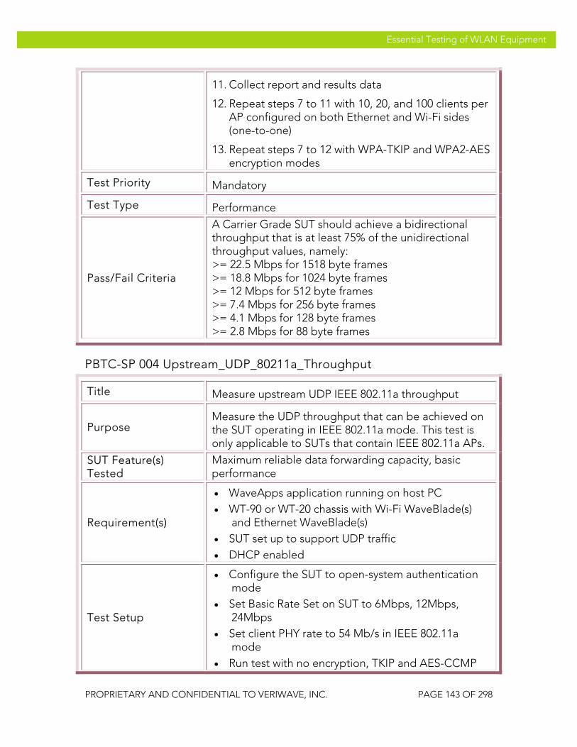
VeriWave, Inc. Essential Testing of WLAN Equipment
PROPRIETARY AND CONFIDENTIAL TO VERIWAVE, INC. PAGE 143 OF 298
Essential Testing of WLAN Equipment
11. Collect report and results data
12. Repeat steps 7 to 11 with 10, 20, and 100 clients per AP configured on both Ethernet and Wi-Fi sides (one-to-one)
13. Repeat steps 7 to 12 with WPA-TKIP and WPA2-AES encryption modes
Test Priority Mandatory
Test Type Performance
Pass/Fail Criteria
A Carrier Grade SUT should achieve a bidirectional throughput that is at least 75% of the unidirectional throughput values, namely: >= 22.5 Mbps for 1518 byte frames >= 18.8 Mbps for 1024 byte frames >= 12 Mbps for 512 byte frames >= 7.4 Mbps for 256 byte frames >= 4.1 Mbps for 128 byte frames >= 2.8 Mbps for 88 byte frames
PBTC-SP 004 Upstream_UDP_80211a_Throughput
Title Measure upstream UDP IEEE 802.11a throughput
Purpose Measure the UDP throughput that can be achieved on the SUT operating in IEEE 802.11a mode. This test is only applicable to SUTs that contain IEEE 802.11a APs.
SUT Feature(s) Tested
Maximum reliable data forwarding capacity, basic performance
Requirement(s)
• WaveApps application running on host PC • WT-90 or WT-20 chassis with Wi-Fi WaveBlade(s)
and Ethernet WaveBlade(s) • SUT set up to support UDP traffic • DHCP enabled
Test Setup
• Configure the SUT to open-system authentication mode
• Set Basic Rate Set on SUT to 6Mbps, 12Mbps, 24Mbps
• Set client PHY rate to 54 Mb/s in IEEE 802.11a mode
• Run test with no encryption, TKIP and AES-CCMP

VeriWave, Inc. Essential Testing of WLAN Equipment
PROPRIETARY AND CONFIDENTIAL TO VERIWAVE, INC. PAGE 144 OF 298
Essential Testing of WLAN Equipment
• Run test with UDP frame sizes: 88, 128, 256, 512, 1024, 1280 and 1518 bytes
• Run test with 1, 10, 20 and 100 clients per AP; for a WLAN controller-based system, at least one test must be run with >1000 clients
Procedure
1. Launch the WaveApps application
2. Select the Throughput Test under the IEEE 802.11.2 Benchmark Test Suite
3. Select the test port(s) (i.e., APs) to use for the test
4. Select SSID and configure the clients to open authentication with no encryption and obtain IP addresses via DHCP
5. Create an Ethernet client group on the correct port(s) with the initial number of Ethernet clients set to 1 per AP
6. Set the initial number of Wi-Fi clients to 1 per AP
7. Select frame sizes of 88, 128, 256, 512, 1024, 1280 and 1518 bytes and UDP traffic type
8. Select Wireless to Ethernet (one-to-one, upstream) mapping
9. Run the test
10. Wait until test completes
11. Collect report and results data
12. Repeat steps 7 to 11 with 10, 20, and 100 clients per AP configured on both Ethernet and Wi-Fi sides (one-to-one)
13. Repeat steps 7 to 12 with WPA-TKIP and WPA2-AES encryption modes
Test Priority Mandatory
Test Type Performance
Pass/Fail Criteria
A Carrier Grade SUT should achieve the following upstream throughput: >= 30 Mbps for 1518 byte frames >= 25 Mbps for 1024 byte frames >= 16 Mbps for 512 byte frames >= 9.9 Mbps for 256 byte frames

VeriWave, Inc. Essential Testing of WLAN Equipment
PROPRIETARY AND CONFIDENTIAL TO VERIWAVE, INC. PAGE 145 OF 298
Essential Testing of WLAN Equipment
>= 5.5 Mbps for 128 byte frames >= 3.8 Mbps for 88 byte frames
PBTC-SP 005 Downstream_UDP_80211a_Throughput
Title Measure downstream UDP IEEE 802.11a throughput
Purpose Measure the UDP throughput that can be achieved on the SUT operating in IEEE 802.11a mode. This test is only applicable to SUTs that contain IEEE 802.11a APs.
SUT Feature(s) Tested
Maximum reliable data forwarding capacity, basic performance
Requirement(s)
• WaveApps application running on host PC • WT-90 or WT-20 chassis with Wi-Fi WaveBlade(s)
and Ethernet WaveBlade(s) • SUT set up to support UDP traffic • DHCP enabled
Test Setup
• Configure the SUT to open-system authentication mode
• Set Basic Rate Set on SUT to 6Mbps, 12Mbps, 24Mbps
• Set client PHY rate to 54 Mb/s in IEEE 802.11a mode
• Run test with no encryption, TKIP and AES-CCMP • Run test with UDP frame sizes: 88, 128, 256, 512,
1024, 1280 and 1518 bytes • Run test with 1, 10, 20 and 100 clients per AP; for a
WLAN controller-based system, at least one test must be run with >1000 clients
Procedure
1. Launch the WaveApps application
2. Select the Throughput Test under the IEEE 802.11.2 Benchmark Test Suite
3. Select the test port(s) (i.e., APs) to use for the test
4. Select SSID and configure the clients to open authentication with no encryption and obtain IP addresses via DHCP
5. Create an Ethernet client group on the correct port(s) with the initial number of Ethernet clients set to 1 per AP
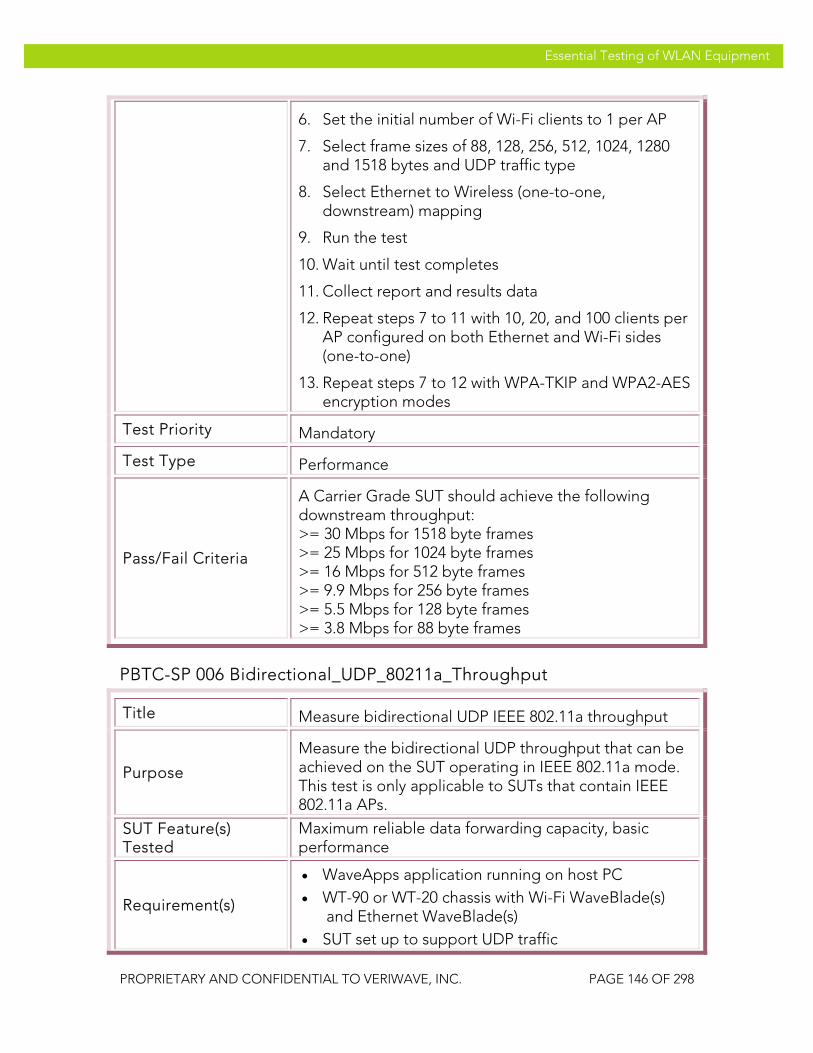
VeriWave, Inc. Essential Testing of WLAN Equipment
PROPRIETARY AND CONFIDENTIAL TO VERIWAVE, INC. PAGE 146 OF 298
Essential Testing of WLAN Equipment
6. Set the initial number of Wi-Fi clients to 1 per AP
7. Select frame sizes of 88, 128, 256, 512, 1024, 1280 and 1518 bytes and UDP traffic type
8. Select Ethernet to Wireless (one-to-one, downstream) mapping
9. Run the test
10. Wait until test completes
11. Collect report and results data
12. Repeat steps 7 to 11 with 10, 20, and 100 clients per AP configured on both Ethernet and Wi-Fi sides (one-to-one)
13. Repeat steps 7 to 12 with WPA-TKIP and WPA2-AES encryption modes
Test Priority Mandatory
Test Type Performance
Pass/Fail Criteria
A Carrier Grade SUT should achieve the following downstream throughput: >= 30 Mbps for 1518 byte frames >= 25 Mbps for 1024 byte frames >= 16 Mbps for 512 byte frames >= 9.9 Mbps for 256 byte frames >= 5.5 Mbps for 128 byte frames >= 3.8 Mbps for 88 byte frames
PBTC-SP 006 Bidirectional_UDP_80211a_Throughput
Title Measure bidirectional UDP IEEE 802.11a throughput
Purpose
Measure the bidirectional UDP throughput that can be achieved on the SUT operating in IEEE 802.11a mode. This test is only applicable to SUTs that contain IEEE 802.11a APs.
SUT Feature(s) Tested
Maximum reliable data forwarding capacity, basic performance
Requirement(s)
• WaveApps application running on host PC • WT-90 or WT-20 chassis with Wi-Fi WaveBlade(s)
and Ethernet WaveBlade(s) • SUT set up to support UDP traffic

VeriWave, Inc. Essential Testing of WLAN Equipment
PROPRIETARY AND CONFIDENTIAL TO VERIWAVE, INC. PAGE 147 OF 298
Essential Testing of WLAN Equipment
• DHCP enabled
Test Setup
• Configure the SUT to open-system authentication mode
• Set Basic Rate Set on SUT to 6Mbps, 12Mbps, 24Mbps
• Set client PHY rate to 54 Mb/s in IEEE 802.11a mode
• Run test with no encryption, TKIP and AES-CCMP • Run test with UDP frame sizes: 88, 128, 256, 512,
1024, 1280 and 1518 bytes • Run test with 1, 10, 20 and 100 clients per AP; for a
WLAN controller-based system, at least one test must be run with >1000 clients
Procedure
1. Launch the WaveApps application
2. Select the Throughput Test under the IEEE 802.11.2 Benchmark Test Suite
3. Select the test port(s) (i.e., APs) to use for the test
4. Select SSID and configure the clients to open authentication with no encryption and obtain IP addresses via DHCP
5. Create an Ethernet client group on the correct port(s) with the initial number of Ethernet clients set to 1 per AP
6. Set the initial number of Wi-Fi clients to 1 per AP
7. Select frame sizes of 88, 128, 256, 512, 1024, 1280 and 1518 bytes and UDP traffic type
8. Select Wireless to Ethernet (one-to-one) mapping with the bidirectional option checked
9. Run the test
10. Wait until test completes
11. Collect report and results data
12. Repeat steps 7 to 11 with 10, 20, and 100 clients per AP configured on both Ethernet and Wi-Fi sides (one-to-one)
13. Repeat steps 7 to 12 with WPA-TKIP and WPA2-AES encryption modes

VeriWave, Inc. Essential Testing of WLAN Equipment
PROPRIETARY AND CONFIDENTIAL TO VERIWAVE, INC. PAGE 148 OF 298
Essential Testing of WLAN Equipment
Test Priority Mandatory
Test Type Performance
Pass/Fail Criteria
A Carrier Grade SUT should achieve a bidirectional throughput that is at least 75% of the unidirectional throughput values, namely: >= 22.5 Mbps for 1518 byte frames >= 18.8 Mbps for 1024 byte frames >= 12 Mbps for 512 byte frames >= 7.4 Mbps for 256 byte frames >= 4.1 Mbps for 128 byte frames >= 2.8 Mbps for 88 byte frames
PBTC-SP 007 Upstream_TCP_80211g_Throughput
Title Measure upstream TCP IEEE 802.11g throughput
Purpose Measure the stateful TCP throughput that can be achieved on the SUT in IEEE 802.11g mode with traffic flowing in the upstream direction
SUT Feature(s) Tested
Maximum reliable TCP data forwarding rate
Requirement(s)
• WaveApps application running on host PC • WT-90 or WT-20 chassis with Wi-Fi WaveBlade(s)
and Ethernet WaveBlade(s) • SUT set up to support TCP traffic • DHCP enabled
Test Setup
• Configure the SUT to open-system authentication mode
• Set Basic Rate Set on SUT to 1Mbps, 2Mbps, 5.5Mbps, 6Mbps, 11Mbps, 12Mbps, 24Mbps
• Set client PHY rate to 54 Mb/s in IEEE 802.11g-only mode
• Run test with no encryption, TKIP and AES-CCMP • Run test with TCP frame sizes: 88, 128, 256, 512,
1024, 1280 and 1518 bytes • Run test with 1, 10, 20 and 100 clients per AP; for a
WLAN controller-based system, at least one test must be run with >1000 clients
Procedure 1. Launch the WaveApps application

VeriWave, Inc. Essential Testing of WLAN Equipment
PROPRIETARY AND CONFIDENTIAL TO VERIWAVE, INC. PAGE 149 OF 298
Essential Testing of WLAN Equipment
2. Select the Throughput Test under the IEEE 802.11.2 Benchmark Test Suite
3. Select the test port(s) (i.e., APs) to use for the test
4. Select SSID and configure the clients to open authentication with no encryption and obtain IP addresses via DHCP
5. Create an Ethernet client group on the correct port(s) with the initial number of Ethernet clients set to 1 per AP
6. Set the initial number of Wi-Fi clients to 1 per AP
7. Select frame sizes of 88, 128, 256, 512, 1024, 1280 and 1518 bytes and TCP traffic type
8. Select Wireless to Ethernet (one-to-one, upstream) mapping
9. Run the test
10. Wait until test completes
11. Collect report and results data
12. Repeat steps 6 to 11 with 10, 20, and 100 clients per AP configured on both Ethernet and Wi-Fi sides (one-to-one)
13. Repeat steps 7 to 12 with WPA-TKIP and WPA2-AES encryption modes
Test Priority High
Test Type Performance
Pass/Fail Criteria
A Carrier Grade SUT should achieve the following upstream stateful TCP throughput: >= 30 Mbps for 1518 byte frames >= 25 Mbps for 1024 byte frames >= 16 Mbps for 512 byte frames >= 9.9 Mbps for 256 byte frames >= 5.5 Mbps for 128 byte frames >= 3.8 Mbps for 88 byte frames
PBTC-SP 008 Downstream_TCP_80211g_Throughput
Title Measure downstream TCP IEEE 80211g throughput

VeriWave, Inc. Essential Testing of WLAN Equipment
PROPRIETARY AND CONFIDENTIAL TO VERIWAVE, INC. PAGE 150 OF 298
Essential Testing of WLAN Equipment
Purpose Measure the stateful TCP throughput that can be achieved on the SUT operating in IEEE 802.11g mode with traffic flowing in the downstream direction
SUT Feature(s) Tested
Maximum reliable TCP data forwarding rate
Requirement(s)
• WaveApps application running on host PC • WT-90 or WT-20 chassis with Wi-Fi WaveBlade(s)
and Ethernet WaveBlade(s) • SUT set up to support TCP traffic • DHCP enabled
Test Setup
• Configure the SUT to open-system authentication mode
• Set Basic Rate Set on SUT to 1Mbps, 2Mbps, 5.5Mbps, 6Mbps, 11Mbps, 12Mbps, 24Mbps
• Set client PHY rate to 54 Mb/s in IEEE 802.11g-only mode
• Run test with no encryption, TKIP and AES-CCMP • Run test with TCP frame sizes: 88, 128, 256, 512,
1024, 1280 and 1518 bytes • Run test with 1, 10, 20 and 100 clients per AP; for a
WLAN controller-based system, at least one test must be run with >1000 clients
Procedure
1. Launch the WaveApps application
2. Select the Throughput Test under the IEEE 802.11.2 Benchmark Test Suite
3. Select the test port(s) (i.e., APs) to use for the test
4. Select SSID and configure the clients to open authentication with no encryption and obtain IP addresses via DHCP
5. Create an Ethernet client group on the correct port(s) with the initial number of Ethernet clients set to 1 per AP
6. Set the initial number of Wi-Fi clients to 1 per AP
7. Select frame sizes of 88, 128, 256, 512, 1024, 1280 and 1518 bytes and TCP traffic type
8. Select Ethernet to Wireless (one-to-one, downstream) mapping

VeriWave, Inc. Essential Testing of WLAN Equipment
PROPRIETARY AND CONFIDENTIAL TO VERIWAVE, INC. PAGE 151 OF 298
Essential Testing of WLAN Equipment
9. Run the test
10. Wait until test completes
11. Collect report and results data
12. Repeat steps 7 to 11 with 10, 20, and 100 clients per AP configured on both Ethernet and Wi-Fi sides (one-to-one)
13. Repeat steps 7 to 12 with WPA-TKIP and WPA2-AES encryption modes
Test Priority High
Test Type Performance
Pass/Fail Criteria
A Carrier Grade SUT should achieve the following downstream stateful TCP throughput: >= 30 Mbps for 1518 byte frames >= 25 Mbps for 1024 byte frames >= 16 Mbps for 512 byte frames >= 9.9 Mbps for 256 byte frames >= 5.5 Mbps for 128 byte frames >= 3.8 Mbps for 88 byte frames
PBTC-SP 009 Upstream_TCP_80211a_Throughput
Title Measure upstream TCP IEEE 80211a Throughput
Purpose
Measure the stateful TCP throughput that can be achieved on the SUT operating in IEEE 802.11a mode with traffic flowing in the upstream direction. This test is only applicable to SUTs that contain IEEE 802.11a APs.
SUT Feature(s) Tested
Maximum reliable TCP data forwarding rate
Requirement(s)
• WaveApps application running on host PC • WT-90 or WT-20 chassis with Wi-Fi WaveBlade(s)
and Ethernet WaveBlade(s) • SUT set up to support TCP traffic • DHCP enabled
Test Setup • Configure the SUT to open-system authentication
mode • Set Basic Rate Set on SUT to 6Mbps, 12Mbps,

VeriWave, Inc. Essential Testing of WLAN Equipment
PROPRIETARY AND CONFIDENTIAL TO VERIWAVE, INC. PAGE 152 OF 298
Essential Testing of WLAN Equipment
24Mbps • Set client PHY rate to 54 Mb/s in IEEE 802.11a
mode • Run test with no encryption, TKIP and AES-CCMP • Run test with TCP frame sizes: 88, 128, 256, 512,
1024, 1280 and 1518 bytes • Run test with 1, 10, 20 and 100 clients per AP; for a
WLAN controller-based system, at least one test must be run with >1000 clients
Procedure
1. Launch the WaveApps application
2. Select the Throughput Test under the IEEE 802.11.2 Benchmark Test Suite
3. Select the test port(s) (i.e., APs) to use for the test
4. Select SSID and configure the clients to open authentication with no encryption and obtain IP addresses via DHCP
5. Create an Ethernet client group on the correct port(s) with the initial number of Ethernet clients set to 1 per AP
6. Set the initial number of Wi-Fi clients to 1 per AP
7. Select frame sizes of 88, 128, 256, 512, 1024, 1280 and 1518 bytes and UDP traffic type
8. Select Wireless to Ethernet (one-to-one, upstream) mapping
9. Run the test
10. Wait until test completes
11. Collect report and results data
12. Repeat steps 7 to 11 with 10, 20, and 100 clients per AP configured on both Ethernet and Wi-Fi sides (one-to-one)
13. Repeat steps 7 to 12 with WPA-TKIP and WPA2-AES encryption modes
Test Priority High
Test Type Performance
Pass/Fail Criteria A Carrier Grade SUT should achieve the following upstream stateful TCP throughput:

VeriWave, Inc. Essential Testing of WLAN Equipment
PROPRIETARY AND CONFIDENTIAL TO VERIWAVE, INC. PAGE 153 OF 298
Essential Testing of WLAN Equipment
>= 30 Mbps for 1518 byte frames >= 25 Mbps for 1024 byte frames >= 16 Mbps for 512 byte frames >= 9.9 Mbps for 256 byte frames >= 5.5 Mbps for 128 byte frames >= 3.8 Mbps for 88 byte frames
PBTC-SP 010 Downstream_TCP_80211a_Throughput
Title Measure downstream TCP IEEE 80211a throughput
Purpose
Measure the stateful TCP throughput that can be achieved on the SUT operating in IEEE 802.11a mode with traffic flowing in the downstream direction. This test is only applicable to SUTs that contain IEEE 802.11a APs.
SUT Feature(s) Tested
Maximum reliable TCP data forwarding rate
Requirement(s)
• WaveApps application running on host PC • WT-90 or WT-20 chassis with Wi-Fi WaveBlade(s)
and Ethernet WaveBlade(s) • SUT set up to support TCP traffic • DHCP enabled
Test Setup
• Configure the SUT to open-system authentication mode
• Set Basic Rate Set on SUT to 6Mbps, 12Mbps, 24Mbps
• Set client PHY rate to 54 Mb/s in IEEE 802.11a mode
• Run test with no encryption, TKIP and AES-CCMP • Run test with TCP frame sizes: 88, 128, 256, 512,
1024, 1280 and 1518 bytes • Run test with 1, 10, 20 and 100 clients per AP; for a
WLAN controller-based system, at least one test must be run with >1000 clients
Procedure
1. Launch the WaveApps application
2. Select the Throughput Test under the IEEE 802.11.2 Benchmark Test Suite
3. Select the test port(s) (i.e., APs) to use for the test

VeriWave, Inc. Essential Testing of WLAN Equipment
PROPRIETARY AND CONFIDENTIAL TO VERIWAVE, INC. PAGE 154 OF 298
Essential Testing of WLAN Equipment
4. Select SSID and configure the clients to open authentication with no encryption and obtain IP addresses via DHCP
5. Create an Ethernet client group on the correct port(s) with the initial number of Ethernet clients set to 1 per AP
6. Set the initial number of Wi-Fi clients to 1 per AP
7. Select frame sizes of 88, 128, 256, 512, 1024, 1280 and 1518 bytes and TCP traffic type
8. Select Ethernet to Wireless (one-to-one, downstream) mapping
9. Run the test
10. Wait until test completes
11. Collect report and results data
12. Repeat steps 7 to 11 with 10, 20, and 100 clients per AP configured on both Ethernet and Wi-Fi sides (one-to-one)
13. Repeat steps 7 to 12 with WPA-TKIP and WPA2-AES encryption modes
Test Priority High
Test Type Performance
Pass/Fail Criteria
A Carrier Grade SUT should achieve the following downstream stateful TCP throughput: >= 30 Mbps for 1518 byte frames >= 25 Mbps for 1024 byte frames >= 16 Mbps for 512 byte frames >= 9.9 Mbps for 256 byte frames >= 5.5 Mbps for 128 byte frames >= 3.8 Mbps for 88 byte frames
PBTC-SP 011 Downstream_UDP_Power_Save_80211g_Throughput
Title Measure downstream UDP IEEE 802.11g throughput with clients in power-save (PS) mode
Purpose Measures the downstream throughput that can be achieved by the SUT when the associated stations are in power save mode (i.e., attempting to minimize

VeriWave, Inc. Essential Testing of WLAN Equipment
PROPRIETARY AND CONFIDENTIAL TO VERIWAVE, INC. PAGE 155 OF 298
Essential Testing of WLAN Equipment
battery power by sleeping between packets). Three listen intervals are tested: 0 (zero) corresponding to Continuous Awake Mode (CAM), which is the baseline; 1 (one) corresponding to doze mode; and 10 (ten), which is considered deep sleep. This test verifies the SUT buffer size and performance while stations are in power save mode using the tested listen intervals.
SUT Feature(s) Tested
SUT PS buffer size and PS protocol handling performance
Requirement(s)
• WaveApps application running on host PC • WT-90 or WT-20 chassis with Wi-Fi WaveBlade(s)
and Ethernet WaveBlade(s) • SUT set up to support UDP traffic • DHCP enabled
Test Setup
• Configure the SUT to open-system authentication mode
• Set Basic Rate Set on SUT to 1Mbps, 2Mbps, 5.5Mbps, 6Mbps, 11Mbps, 12Mbps, 24Mbps
• Set client PHY rate to 54 Mb/s in IEEE 802.11g-only mode
• Run test with no encryption, TKIP and AES-CCMP • Run test with UDP frame sizes: 88, 128, 256, 512,
1024, 1280 and 1518 bytes • Run test with 1, 10, 20 and 100 clients per AP; for a
WLAN controller-based system, at least one test must be run with >1000 clients
Procedure
1. Launch the WaveApps application
2. Select the Power-Save Throughput Test under the IEEE 802.11.2 Benchmark Test Suite
3. Select the test port(s) (i.e., APs) to use for the test
4. Select SSID and configure the clients to open authentication with no encryption and obtain IP addresses via DHCP
5. Create an Ethernet client group on the correct port(s) with the initial number of Ethernet clients set to 1 per AP
6. Set the initial number of Wi-Fi clients to 1 per AP
7. Select frame sizes of 88, 128, 256, 512, 1024, 1280

VeriWave, Inc. Essential Testing of WLAN Equipment
PROPRIETARY AND CONFIDENTIAL TO VERIWAVE, INC. PAGE 156 OF 298
Essential Testing of WLAN Equipment
and 1518 bytes and UDP traffic type
8. Set the power-save listen interval to 0 (no power save)
9. Select Ethernet to Wireless (one-to-one, downstream) mapping
10. Run the test
11. Wait until test completes
12. Collect report and results data
13. Repeat steps 7 to 12 with 10, 20, and 100 clients per AP configured on both Ethernet and Wi-Fi sides (one-to-one)
14. Repeat steps 7 to 13 with WPA-TKIP and WPA2-AES encryption modes
15. Repeat steps 7 to 14 with listen intervals of 1 and 10
Test Priority High
Test Type Power Save Performance
Pass/Fail Criteria
With a listen interval of 0, the SUT throughput should be equal to that measured with the downstream IEEE 802.11g throughput test
With a listen interval of 1, the SUT throughput should be >80% of that measured with the downstream IEEE 802.11g throughput test
With a listen interval of 10, the SUT throughput should be >50% of that measured with the downstream IEEE 802.11g throughput test
PBTC-SP 012 Downstream_UDP_Power_Save_80211a_Throughput
Title Measure downstream UDP IEEE 802.11a throughput with clients in power-save (PS) mode
Purpose
Measures the downstream throughput that can be achieved by the SUT when the associated stations are in power save mode (i.e., attempting to minimize battery power by sleeping between packets). Three listen intervals are tested: 0 (zero) corresponding to Continuous Awake Mode (CAM), which is the baseline; 1 (one) corresponding to doze mode; and 10 (ten),

VeriWave, Inc. Essential Testing of WLAN Equipment
PROPRIETARY AND CONFIDENTIAL TO VERIWAVE, INC. PAGE 157 OF 298
Essential Testing of WLAN Equipment
which is considered deep sleep. This test verifies the SUT buffer size and performance while stations are in power save mode using the tested listen intervals. This test is only applicable to SUTs that contain IEEE 802.11a APs.
SUT Feature(s) Tested
SUT PS buffer size and PS protocol handling performance
Requirement(s)
• WaveApps application running on host PC • WT-90 or WT-20 chassis with Wi-Fi WaveBlade(s)
and Ethernet WaveBlade(s) • SUT set up to support UDP traffic • DHCP enabled
Test Setup
• Configure the SUT to open-system authentication mode
• Set Basic Rate Set on SUT to 6Mbps, 12Mbps, 24Mbps
• Set client PHY rate to 54 Mb/s in IEEE 802.11a mode
• Run test with no encryption, TKIP and AES-CCMP • Run test with UDP frame sizes: 88, 128, 256, 512,
1024, 1280 and 1518 bytes • Run test with 1, 10, 20 and 100 clients per AP; for a
WLAN controller-based system, at least one test must be run with >1000 clients
Procedure
1. Launch the WaveApps application
2. Select the Power-Save Throughput Test under the IEEE 802.11.2 Benchmark Test Suite
3. Select the test port(s) (i.e., APs) to use for the test
4. Select SSID and configure the clients to open authentication with no encryption and obtain IP addresses via DHCP
5. Create an Ethernet client group on the correct port(s) with the initial number of Ethernet clients set to 1 per AP
6. Set the initial number of Wi-Fi clients to 1 per AP
7. Select frame sizes of 88, 128, 256, 512, 1024, 1280 and 1518 bytes and UDP traffic type
8. Set the power-save listen interval to 0 (no power

VeriWave, Inc. Essential Testing of WLAN Equipment
PROPRIETARY AND CONFIDENTIAL TO VERIWAVE, INC. PAGE 158 OF 298
Essential Testing of WLAN Equipment
save)
9. Select Ethernet to Wireless (one-to-one, downstream) mapping
10. Run the test
11. Wait until test completes
12. Collect report and results data
13. Repeat steps 7 to 12 with 10, 20, and 100 clients per AP configured on both Ethernet and Wi-Fi sides (one-to-one)
14. Repeat steps 7 to 13 with WPA-TKIP and WPA2-AES encryption modes
15. Repeat steps 7 to 14 with listen intervals of 1 and 10
Test Priority High
Test Type Power Save Performance
Pass/Fail Criteria
With a listen interval of 0, the SUT throughput should be equal to that measured with the downstream IEEE 802.11a throughput test
With a listen interval of 1, the SUT throughput should be >80% of that measured with the downstream IEEE 802.11a throughput test
With a listen interval of 10, the SUT throughput should be >50% of that measured with the downstream IEEE 802.11a throughput test
PBTC-SP 013 Downstream_TCP_Power_Save_80211g_Throughput
Title Measure downstream stateful-TCP IEEE 802.11g throughput with clients in power-save (PS) mode
Purpose
Measures the downstream throughput that can be achieved by the SUT when the associated stations are in power save mode (i.e., attempting to minimize battery power by sleeping between packets). Three listen intervals are tested: 0 (zero) corresponding to Continuous Awake Mode (CAM), which is the baseline; 1 (one) corresponding to doze mode; and 10 (ten), which is considered deep sleep. This test verifies the SUT buffer size and performance while stations are in power save mode using the tested listen intervals. The

VeriWave, Inc. Essential Testing of WLAN Equipment
PROPRIETARY AND CONFIDENTIAL TO VERIWAVE, INC. PAGE 159 OF 298
Essential Testing of WLAN Equipment
use of stateful TCP traffic determines the impact of SUT power-save handling algorithms on TCP applications.
SUT Feature(s) Tested
SUT PS buffer size and PS protocol handling performance
Requirement(s)
• WaveApps application running on host PC • WT-90 or WT-20 chassis with Wi-Fi WaveBlade(s)
and Ethernet WaveBlade(s) • SUT set up to support TCP traffic • DHCP enabled
Test Setup
• Configure the SUT to open-system authentication mode
• Set Basic Rate Set on SUT to 1Mbps, 2Mbps, 5.5Mbps, 6Mbps, 11Mbps, 12Mbps, 24Mbps
• Set client PHY rate to 54 Mb/s in IEEE 802.11g-only mode
• Run test with no encryption, TKIP and AES-CCMP • Run test with stateful TCP frame sizes: 88, 128, 256,
512, 1024, 1280 and 1518 bytes • Run test with 1, 10, 20 and 100 clients per AP; for a
WLAN controller-based system, at least one test must be run with >1000 clients
Procedure
1. Launch the WaveApps application
2. Select the Power-Save Throughput Test under the IEEE 802.11.2 Benchmark Test Suite
3. Select the test port(s) (i.e., APs) to use for the test
4. Select SSID and configure the clients to open authentication with no encryption and obtain IP addresses via DHCP
5. Create an Ethernet client group on the correct port(s) with the initial number of Ethernet clients set to 1 per AP
6. Set the initial number of Wi-Fi clients to 1 per AP
7. Select frame sizes of 88, 128, 256, 512, 1024, 1280 and 1518 bytes and TCP traffic type
8. Set the power-save listen interval to 0 (no power save)
9. Select Ethernet to Wireless (one-to-one, downstream) mapping
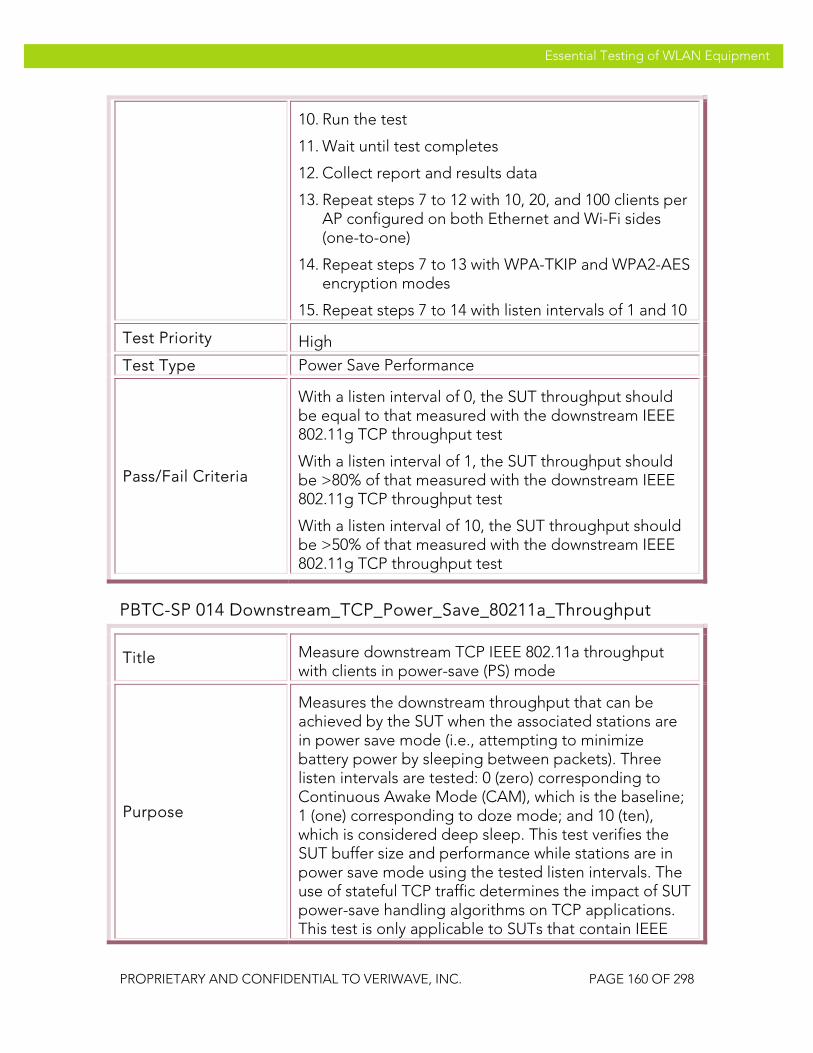
VeriWave, Inc. Essential Testing of WLAN Equipment
PROPRIETARY AND CONFIDENTIAL TO VERIWAVE, INC. PAGE 160 OF 298
Essential Testing of WLAN Equipment
10. Run the test
11. Wait until test completes
12. Collect report and results data
13. Repeat steps 7 to 12 with 10, 20, and 100 clients per AP configured on both Ethernet and Wi-Fi sides (one-to-one)
14. Repeat steps 7 to 13 with WPA-TKIP and WPA2-AES encryption modes
15. Repeat steps 7 to 14 with listen intervals of 1 and 10
Test Priority High
Test Type Power Save Performance
Pass/Fail Criteria
With a listen interval of 0, the SUT throughput should be equal to that measured with the downstream IEEE 802.11g TCP throughput test
With a listen interval of 1, the SUT throughput should be >80% of that measured with the downstream IEEE 802.11g TCP throughput test
With a listen interval of 10, the SUT throughput should be >50% of that measured with the downstream IEEE 802.11g TCP throughput test
PBTC-SP 014 Downstream_TCP_Power_Save_80211a_Throughput
Title Measure downstream TCP IEEE 802.11a throughput with clients in power-save (PS) mode
Purpose
Measures the downstream throughput that can be achieved by the SUT when the associated stations are in power save mode (i.e., attempting to minimize battery power by sleeping between packets). Three listen intervals are tested: 0 (zero) corresponding to Continuous Awake Mode (CAM), which is the baseline; 1 (one) corresponding to doze mode; and 10 (ten), which is considered deep sleep. This test verifies the SUT buffer size and performance while stations are in power save mode using the tested listen intervals. The use of stateful TCP traffic determines the impact of SUT power-save handling algorithms on TCP applications. This test is only applicable to SUTs that contain IEEE

VeriWave, Inc. Essential Testing of WLAN Equipment
PROPRIETARY AND CONFIDENTIAL TO VERIWAVE, INC. PAGE 161 OF 298
Essential Testing of WLAN Equipment
802.11a APs.
SUT Feature(s) Tested
SUT PS buffer size and PS protocol handling performance
Requirement(s)
• WaveApps application running on host PC • WT-90 or WT-20 chassis with Wi-Fi WaveBlade(s)
and Ethernet WaveBlade(s) • SUT set up to support TCP traffic • DHCP enabled
Test Setup
• Configure the SUT to open-system authentication mode
• Set Basic Rate Set on SUT to 6Mbps, 12Mbps, 24Mbps
• Set client PHY rate to 54 Mb/s in IEEE 802.11a mode
• Run test with no encryption, TKIP and AES-CCMP • Run test with TCP frame sizes: 88, 128, 256, 512,
1024, 1280 and 1518 bytes • Run test with 1, 10, 20 and 100 clients per AP; for a
WLAN controller-based system, at least one test must be run with >1000 clients
Procedure
1. Launch the WaveApps application
2. Select the Power-Save Throughput Test under the IEEE 802.11.2 Benchmark Test Suite
3. Select the test port(s) (i.e., APs) to use for the test
4. Select SSID and configure the clients to open authentication with no encryption and obtain IP addresses via DHCP
5. Create an Ethernet client group on the correct port(s) with the initial number of Ethernet clients set to 1 per AP
6. Set the initial number of Wi-Fi clients to 1 per AP
7. Select frame sizes of 88, 128, 256, 512, 1024, 1280 and 1518 bytes and TCP traffic type
8. Set the power-save listen interval to 0 (no power save)
9. Select Ethernet to Wireless (one-to-one, downstream) mapping

VeriWave, Inc. Essential Testing of WLAN Equipment
PROPRIETARY AND CONFIDENTIAL TO VERIWAVE, INC. PAGE 162 OF 298
Essential Testing of WLAN Equipment
10. Run the test
11. Wait until test completes
12. Collect report and results data
13. Repeat steps 7 to 12 with 10, 20, and 100 clients per AP configured on both Ethernet and Wi-Fi sides (one-to-one)
14. Repeat steps 7 to 13 with WPA-TKIP and WPA2-AES encryption modes
15. Repeat steps 7 to 14 with listen intervals of 1 and 10
Test Priority High
Test Type Power Save Performance
Pass/Fail Criteria
With a listen interval of 0, the SUT throughput should be equal to that measured with the downstream IEEE 802.11a TCP throughput test
With a listen interval of 1, the SUT throughput should be >80% of that measured with the downstream IEEE 802.11a TCP throughput test
With a listen interval of 10, the SUT throughput should be >50% of that measured with the downstream IEEE 802.11a TCP throughput test
Packet Latency
The following latency tests measure the delay required for packets to be forwarded through the SUT using a variety of frame sizes under increasing client load. Delay-sensitive services such as streaming video and VoIP require low latency for a high-quality user experience. The latency tests present the SUT with an intended load for each frame size and measures the time it takes for each packet to travel from the source port to the destination port through the SUT.
The intended load is divided equally between SUT ports, and should be adjusted to be just below the SUT throughput (i.e., the value measured using a previous throughput test). The latency tests are conducted with a variety of frame sizes, numbers of clients, security modes, operating bands, and directions (i.e., upstream and downstream).
PBTC-SP 020 Upstream_80211g_Packet_Latency
Title Measure upstream packet latency

VeriWave, Inc. Essential Testing of WLAN Equipment
PROPRIETARY AND CONFIDENTIAL TO VERIWAVE, INC. PAGE 163 OF 298
Essential Testing of WLAN Equipment
Purpose Measure the packet latencies imposed on the WLAN client traffic by the SUT
SUT Feature(s) Tested
Buffering efficiency, datapath and forwarding performance
Requirement(s)
• WaveApps application running on host PC • WT-90 or WT-20 chassis with Wi-Fi WaveBlade(s)
and Ethernet WaveBlade(s) • SUT set up to support UDP traffic • DHCP enabled
Test Setup
• Configure the SUT to open-system authentication mode
• Set Basic Rate Set on SUT to 1Mbps, 2Mbps, 5.5Mbps, 6Mbps, 11Mbps, 12Mbps, 24Mbps
• Set client PHY rate to 54 Mb/s in IEEE 802.11g-only mode
• Run test with no encryption, TKIP and AES-CCMP • Run test with UDP frame sizes: 88, 128, 256, 512,
1024, 1280 and 1518 bytes • Run test with 1, 10, 20 and 100 clients per AP; for a
WLAN controller-based system, at least one test must be run with >1000 clients
• Set intended load (ILOAD) for each frame size to 90% of the throughput of the SUT as obtained from the throughput tests. If the SUT throughput is unknown, use 802.3 defaults
Procedure
1. Launch the WaveApps application
2. Select the Latency Test under the IEEE 802.11.2 Benchmark Test Suite
3. Select the test port(s) (i.e., APs) to use for the test
4. Select SSID and configure the clients to open authentication with no encryption and obtain IP addresses via DHCP
5. Create an Ethernet client group on the correct port(s) with the initial number of Ethernet clients set to 1 per AP
6. Set the initial number of Wi-Fi clients to 1 per AP
7. Adjust the intended load (ILOAD) table to target traffic load as per test setup details above, with

VeriWave, Inc. Essential Testing of WLAN Equipment
PROPRIETARY AND CONFIDENTIAL TO VERIWAVE, INC. PAGE 164 OF 298
Essential Testing of WLAN Equipment
frame sizes of 88, 128, 256, 512, 1024, 1280 and 1518 bytes and UDP traffic type
8. Select Wireless to Ethernet (one-to-one, upstream) mapping
9. Run the test
10. Wait until test completes
11. Collect report and results data
12. Repeat steps 5 to 11 with 10, 20, and 100 clients per AP configured on both Ethernet and Wi-Fi sides (one-to-one)
13. Repeat steps 5 to 12 with WPA-TKIP and WPA2-AES encryption modes
Test Priority Mandatory
Test Type Performance
Pass/Fail Criteria
A Carrier Grade SUT should not impose a packet latency of more than 10 milliseconds under the specified loading in order to support delay-sensitive multimedia traffic.
PBTC-SP 021 Downstream_80211g_Packet_Latency
Title Measure downstream packet latency
Purpose Measure the packet latencies imposed on the WLAN client traffic by the SUT
SUT Feature(s) Tested
Buffering efficiency, datapath and forwarding performance
Requirement(s)
• WaveApps application running on host PC • WT-90 or WT-20 chassis with Wi-Fi WaveBlade(s)
and Ethernet WaveBlade(s) • SUT set up to support UDP traffic • DHCP enabled
Test Setup
• Configure the SUT to open-system authentication mode
• Set Basic Rate Set on SUT to 1Mbps, 2Mbps, 5.5Mbps, 6Mbps, 11Mbps, 12Mbps, 24Mbps
• Set client PHY rate to 54 Mb/s in IEEE 802.11g-only
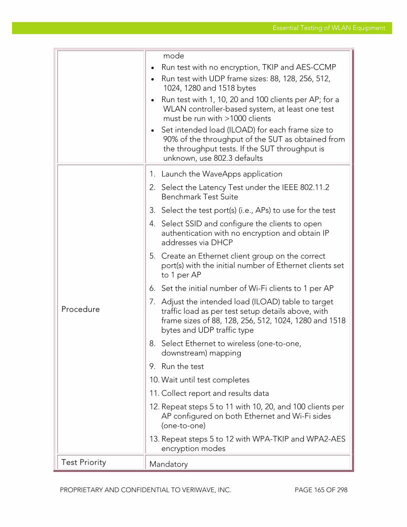
VeriWave, Inc. Essential Testing of WLAN Equipment
PROPRIETARY AND CONFIDENTIAL TO VERIWAVE, INC. PAGE 165 OF 298
Essential Testing of WLAN Equipment
mode • Run test with no encryption, TKIP and AES-CCMP • Run test with UDP frame sizes: 88, 128, 256, 512,
1024, 1280 and 1518 bytes • Run test with 1, 10, 20 and 100 clients per AP; for a
WLAN controller-based system, at least one test must be run with >1000 clients
• Set intended load (ILOAD) for each frame size to 90% of the throughput of the SUT as obtained from the throughput tests. If the SUT throughput is unknown, use 802.3 defaults
Procedure
1. Launch the WaveApps application
2. Select the Latency Test under the IEEE 802.11.2 Benchmark Test Suite
3. Select the test port(s) (i.e., APs) to use for the test
4. Select SSID and configure the clients to open authentication with no encryption and obtain IP addresses via DHCP
5. Create an Ethernet client group on the correct port(s) with the initial number of Ethernet clients set to 1 per AP
6. Set the initial number of Wi-Fi clients to 1 per AP
7. Adjust the intended load (ILOAD) table to target traffic load as per test setup details above, with frame sizes of 88, 128, 256, 512, 1024, 1280 and 1518 bytes and UDP traffic type
8. Select Ethernet to wireless (one-to-one, downstream) mapping
9. Run the test
10. Wait until test completes
11. Collect report and results data
12. Repeat steps 5 to 11 with 10, 20, and 100 clients per AP configured on both Ethernet and Wi-Fi sides (one-to-one)
13. Repeat steps 5 to 12 with WPA-TKIP and WPA2-AES encryption modes
Test Priority Mandatory

VeriWave, Inc. Essential Testing of WLAN Equipment
PROPRIETARY AND CONFIDENTIAL TO VERIWAVE, INC. PAGE 166 OF 298
Essential Testing of WLAN Equipment
Test Type Performance
Pass/Fail Criteria
A Carrier Grade SUT should not impose a packet latency of more than 10 milliseconds under the specified loading in order to support delay-sensitive multimedia traffic.
PBTC-SP 022 Upstream_80211a_Packet_Latency
Title Measure upstream packet latency
Purpose Measure the packet latencies imposed on the WLAN client traffic by the SUT. This test is only applicable to SUTs that contain IEEE 802.11a APs.
SUT Feature(s) Tested
Buffering efficiency, datapath and forwarding performance
Requirement(s)
• WaveApps application running on host PC • WT-90 or WT-20 chassis with Wi-Fi WaveBlade(s)
and Ethernet WaveBlade(s) • SUT set up to support UDP traffic • DHCP enabled
Test Setup
• Configure the SUT to open-system authentication mode
• Set Basic Rate Set on SUT to 6Mbps, 12Mbps, 24Mbps
• Set client PHY rate to 54 Mb/s in IEEE 802.11a mode
• Run test with no encryption, TKIP and AES-CCMP • Run test with UDP frame sizes: 88, 128, 256, 512,
1024, 1280 and 1518 bytes • Run test with 1, 10, 20 and 100 clients per AP; for a
WLAN controller-based system, at least one test must be run with >1000 clients
• Set intended load (ILOAD) for each frame size to 90% of the throughput of the SUT as obtained from the throughput tests. If the SUT throughput is unknown, use 802.3 defaults
Procedure 1. Launch the WaveApps application
2. Select the Latency Test under the IEEE 802.11.2 Benchmark Test Suite

VeriWave, Inc. Essential Testing of WLAN Equipment
PROPRIETARY AND CONFIDENTIAL TO VERIWAVE, INC. PAGE 167 OF 298
Essential Testing of WLAN Equipment
3. Select the test port(s) (i.e., APs) to use for the test
4. Select SSID and configure the clients to open authentication with no encryption and obtain IP addresses via DHCP
5. Create an Ethernet client group on the correct port(s) with the initial number of Ethernet clients set to 1 per AP
6. Set the initial number of Wi-Fi clients to 1 per AP
7. Adjust the intended load (ILOAD) table to target traffic load as per test setup details above, with frame sizes of 88, 128, 256, 512, 1024, 1280 and 1518 bytes and UDP traffic type
8. Select Wireless to Ethernet (one-to-one, upstream) mapping
9. Run the test
10. Wait until test completes
11. Collect report and results data
12. Repeat steps 5 to 11 with 10, 20, and 100 clients per AP configured on both Ethernet and Wi-Fi sides (one-to-one)
13. Repeat steps 5 to 12 with WPA-TKIP and WPA2-AES encryption modes
Test Priority Mandatory
Test Type Performance
Pass/Fail Criteria
A Carrier Grade SUT should not impose a packet latency of more than 10 milliseconds under the specified loading in order to support delay-sensitive multimedia traffic.
PBTC-SP 023 Downstream_80211a_Packet_Latency
Title Measure downstream packet latency
Purpose Measure the packet latencies imposed on the WLAN client traffic by the SUT. This test is only applicable to SUTs that contain IEEE 802.11a APs.
SUT Feature(s) Buffering efficiency, datapath and forwarding

VeriWave, Inc. Essential Testing of WLAN Equipment
PROPRIETARY AND CONFIDENTIAL TO VERIWAVE, INC. PAGE 168 OF 298
Essential Testing of WLAN Equipment
Tested performance
Requirement(s)
• WaveApps application running on host PC • WT-90 or WT-20 chassis with Wi-Fi WaveBlade(s)
and Ethernet WaveBlade(s) • SUT set up to support UDP traffic • DHCP enabled
Test Setup
• Configure the SUT to open-system authentication mode
• Set Basic Rate Set on SUT to 6Mbps, 12Mbps, 24Mbps
• Set client PHY rate to 54 Mb/s in IEEE 802.11a mode
• Run test with no encryption, TKIP and AES-CCMP • Run test with UDP frame sizes: 88, 128, 256, 512,
1024, 1280 and 1518 bytes • Run test with 1, 10, 20 and 100 clients per AP; for a
WLAN controller-based system, at least one test must be run with >1000 clients
• Set intended load (ILOAD) for each frame size to 90% of the throughput of the SUT as obtained from the throughput tests. If the SUT throughput is unknown, use 802.3 defaults
Procedure
1. Launch the WaveApps application
2. Select the Latency Test under the IEEE 802.11.2 Benchmark Test Suite
3. Select the test port(s) (i.e., APs) to use for the test
4. Select SSID and configure the clients to open authentication with no encryption and obtain IP addresses via DHCP
5. Create an Ethernet client group on the correct port(s) with the initial number of Ethernet clients set to 1 per AP
6. Set the initial number of Wi-Fi clients to 1 per AP
7. Adjust the intended load (ILOAD) table to target traffic load as per test setup details above, with frame sizes of 88, 128, 256, 512, 1024, 1280 and 1518 bytes and UDP traffic type
8. Select Ethernet to wireless (one-to-one,

VeriWave, Inc. Essential Testing of WLAN Equipment
PROPRIETARY AND CONFIDENTIAL TO VERIWAVE, INC. PAGE 169 OF 298
Essential Testing of WLAN Equipment
downstream) mapping
9. Run the test
10. Wait until test completes
11. Collect report and results data
12. Repeat steps 5 to 11 with 10, 20, and 100 clients per AP configured on both Ethernet and Wi-Fi sides (one-to-one)
13. Repeat steps 5 to 12 with WPA-TKIP and WPA2-AES encryption modes
Test Priority Mandatory
Test Type Performance
Pass/Fail Criteria
A Carrier Grade SUT should not impose a packet latency of more than 10 milliseconds under the specified loading in order to support delay-sensitive multimedia traffic.
Packet Loss The packet loss tests measure the performance of the SUT at specific load factors for a variety of frame sizes. Two metrics are measured during a packet loss test: the forwarding rate and the packet loss ratio. The forwarding rate quantifies the rate at which packets are successfully received, while the packet loss ratio provides the percentage of dropped packets as a fraction of the injected packets. These measurements quantify the ability of the SUT to forward packets with low or zero loss over the entire range of traffic loads that may be placed upon it in an actual network.
The offered load is divided equally across SUT ports, and ranges from 20% to 100% of the (previously measured) throughput performance of the SUT at that frame size. That is, if the SUT throughput was measured at 10,000 frames/second at a specific frame size, the offered load should be set to 2,000, 4,000, 6,000, 8,000 and 10,000 frames/second. The packet loss tests are conducted with a variety of frame sizes, numbers of clients, security modes, operating bands, and directions (i.e., upstream and downstream).
PBTC-SP 030 Upstream_80211g_Packet_Loss
Title Measure upstream UDP packet loss
Purpose Measure the forwarding rate and packet loss ratios for a range of offered loads over the traffic handling capacity of the SUT

VeriWave, Inc. Essential Testing of WLAN Equipment
PROPRIETARY AND CONFIDENTIAL TO VERIWAVE, INC. PAGE 170 OF 298
Essential Testing of WLAN Equipment
SUT Feature(s) Tested
Uniform traffic handling capacity of datapath, anomalous forwarding performance at lower loads, instabilities
Requirement(s)
• WaveApps application running on host PC • WT-90 or WT-20 chassis with Wi-Fi WaveBlade(s)
and Ethernet WaveBlade(s) • SUT set up to support UDP traffic • DHCP enabled
Test Setup
• Configure the SUT with open-system authentication mode
• Set Basic Rate Set on SUT to 1Mbps, 2Mbps, 5.5Mbps, 6Mbps, 11Mbps, 12Mbps, 24Mbps
• Set client PHY rate to 54 Mb/s in IEEE 802.11g-only mode
• Run test with no encryption, TKIP and AES-CCMP • Run test with UDP frame sizes: 88, 128, 256, 512,
1024, 1280 and 1518 bytes • Run test with 1, 10, 20 and 100 clients per AP; for a
WLAN controller-based system, at least one test must be run with >1000 clients
• For each frame size, set intended load (ILOAD) values to 10%, 20%, 40%, 60%, 80% and 100% of the throughput of the SUT as obtained from UDP throughput tests. If the SUT throughput is unknown, use the theoretical maximum medium capacity of the IEEE 802.11g channel for the specified frame size, multiplied by the number of SUT ports, as the throughput.
Procedure
1. Launch the WaveApps application
2. Select the Packet Loss Test under the IEEE 802.11.2 Benchmark Test Suite
3. Select the test port(s) (i.e., APs) to use for the test
4. Select SSID and configure the clients to open authentication with no encryption and obtain IP addresses via DHCP
5. Create an Ethernet client group on the correct port(s) with the initial number of Ethernet clients set to 1 per AP
6. Set the initial number of Wi-Fi clients to 1 per AP

VeriWave, Inc. Essential Testing of WLAN Equipment
PROPRIETARY AND CONFIDENTIAL TO VERIWAVE, INC. PAGE 171 OF 298
Essential Testing of WLAN Equipment
7. Select the initial frame size as 88 bytes, and UDP traffic type
8. Set up the ILOAD table values as described in the Test Setup section above
9. Select Wireless to Ethernet (one-to-one, upstream) mapping
10. Run the test
11. Wait until test completes
12. Collect report and results data
13. Repeat steps 7 to 12 with frame sizes of 128, 256, 512, 1024 and 1518 bytes
14. Repeat steps 7 to 13 with 10, 20, and 100 clients per AP configured on both Ethernet and Wi-Fi sides (one-to-one)
15. Repeat steps 7 to 14 with WPA-TKIP and WPA2-AES encryption modes
Test Priority Mandatory
Test Type Performance
Pass/Fail Criteria A Carrier Grade SUT should show under 1% packet loss at all frame sizes equal to or less than the measured throughput performance.
PBTC-SP 031 Downstream_80211g_Packet_Loss
Title Measure downstream UDP Packet Loss
Purpose Measure the forwarding rate and packet loss ratios for a range of offered loads over the traffic handling capacity of the SUT
SUT Feature(s) Tested
Uniform traffic handling capacity of datapath, anomalous forwarding performance at lower loads, instabilities
Requirement(s)
• WaveApps application running on host PC • WT-90 or WT-20 chassis with Wi-Fi WaveBlade(s)
and Ethernet WaveBlade(s) • SUT set up to support UDP traffic • DHCP enabled

VeriWave, Inc. Essential Testing of WLAN Equipment
PROPRIETARY AND CONFIDENTIAL TO VERIWAVE, INC. PAGE 172 OF 298
Essential Testing of WLAN Equipment
Test Setup
• Configure the SUT with open-system authentication mode
• Set Basic Rate Set on SUT to 1Mbps, 2Mbps, 5.5Mbps, 6Mbps, 11Mbps, 12Mbps, 24Mbps
• Set client PHY rate to 54 Mb/s in IEEE 802.11g-only mode
• Run test with no encryption, TKIP and AES-CCMP • Run test with UDP frame sizes: 88, 128, 256, 512,
1024, 1280 and 1518 bytes • Run test with 1, 10, 20 and 100 clients per AP; for a
WLAN controller-based system, at least one test must be run with >1000 clients
• For each frame size, set intended load (ILOAD) values to 10%, 20%, 40%, 60%, 80% and 100% of the throughput of the SUT as obtained from UDP throughput tests. If the SUT throughput is unknown, use the theoretical maximum medium capacity of the IEEE 802.11g channel for the specified frame size, multiplied by the number of SUT ports, as the throughput.
Procedure
1. Launch the WaveApps application
2. Select the Packet Loss Test under the IEEE 802.11.2 Benchmark Test Suite
3. Select the test port(s) (i.e., APs) to use for the test
4. Select SSID and configure the clients to open authentication with no encryption and obtain IP addresses via DHCP
5. Create an Ethernet client group on the correct port(s) with the initial number of Ethernet clients set to 1 per AP
6. Set the initial number of Wi-Fi clients to 1 per AP
7. Select the initial frame size as 88 bytes, and UDP traffic type
8. Set up the ILOAD table values as described in the Test Setup section above
9. Select Wireless to Ethernet (one-to-one, downstream) mapping
10. Run the test

VeriWave, Inc. Essential Testing of WLAN Equipment
PROPRIETARY AND CONFIDENTIAL TO VERIWAVE, INC. PAGE 173 OF 298
Essential Testing of WLAN Equipment
11. Wait until test completes
12. Collect report and results data
13. Repeat steps 7 to 12 with frame sizes of 128, 256, 512, 1024 and 1518 bytes
14. Repeat steps 7 to 13 with 10, 20, and 100 clients per AP configured on both Ethernet and Wi-Fi sides (one-to-one)
15. Repeat steps 7 to 14 with WPA-TKIP and WPA2-AES encryption modes
Test Priority Mandatory
Test Type Performance
Pass/Fail Criteria A Carrier Grade SUT should show under 1% packet loss at all frame sizes equal to or less than the measured throughput performance.
PBTC-SP 032 Upstream_80211a_Packet_Loss
Title Measure upstream UDP packet loss with
Purpose
Measure the forwarding rate and packet loss ratios for a range of offered loads over the traffic handling capacity of the SUT. This test is only applicable to SUTs that contain IEEE 802.11a APs.
SUT Feature(s) Tested
Uniform traffic handling capacity of datapath, anomalous forwarding performance at lower loads, instabilities
Requirement(s)
• WaveApps application running on host PC • WT-90 or WT-20 chassis with Wi-Fi WaveBlade(s)
and Ethernet WaveBlade(s) • SUT set up to support UDP traffic • DHCP enabled
Test Setup
• Configure the SUT with open-system authentication mode
• Set Basic Rate Set on SUT to 6Mbps, 12Mbps, 24Mbps
• Set client PHY rate to 54 Mb/s in IEEE 802.11a mode
• Run test with no encryption, TKIP and AES-CCMP

VeriWave, Inc. Essential Testing of WLAN Equipment
PROPRIETARY AND CONFIDENTIAL TO VERIWAVE, INC. PAGE 174 OF 298
Essential Testing of WLAN Equipment
• Run test with UDP frame sizes: 88, 128, 256, 512, 1024, 1280 and 1518 bytes
• Run test with 1, 10, 20 and 100 clients per AP; for a WLAN controller-based system, at least one test must be run with >1000 clients
• For each frame size, set intended load (ILOAD) values to 10%, 20%, 40%, 60%, 80% and 100% of the throughput of the SUT as obtained from UDP throughput tests. If the SUT throughput is unknown, use the theoretical maximum medium capacity of the IEEE 802.11g channel for the specified frame size, multiplied by the number of SUT ports, as the throughput.
Procedure
1. Launch the WaveApps application
2. Select the Packet Loss Test under the IEEE 802.11.2 Benchmark Test Suite
3. Select the test port(s) (i.e., APs) to use for the test
4. Select SSID and configure the clients to open authentication with no encryption and obtain IP addresses via DHCP
5. Create an Ethernet client group on the correct port(s) with the initial number of Ethernet clients set to 1 per AP
6. Set the initial number of Wi-Fi clients to 1 per AP
7. Select the initial frame size as 88 bytes, and UDP traffic type
8. Set up the ILOAD table values as described in the Test Setup section above
9. Select Wireless to Ethernet (one-to-one, upstream) mapping
10. Run the test
11. Wait until test completes
12. Collect report and results data
13. Repeat steps 7 to 12 with frame sizes of 128, 256, 512, 1024 and 1518 bytes
14. Repeat steps 7 to 13 with 10, 20, and 100 clients per AP configured on both Ethernet and Wi-Fi sides (one-to-one)

VeriWave, Inc. Essential Testing of WLAN Equipment
PROPRIETARY AND CONFIDENTIAL TO VERIWAVE, INC. PAGE 175 OF 298
Essential Testing of WLAN Equipment
15. Repeat steps 7 to 14 with WPA-TKIP and WPA2-AES encryption modes
Test Priority Mandatory
Test Type Performance
Pass/Fail Criteria A Carrier Grade SUT should show under 1% packet loss at all frame sizes equal to or less than the measured throughput performance.
PBTC-SP 033 Downstream_80211a_Packet_Loss
Title Measure downstream UDP Packet Loss
Purpose
Measure the forwarding rate and packet loss ratios for a range of offered loads over the traffic handling capacity of the SUT. This test is only applicable to SUTs that contain IEEE 802.11a APs.
SUT Feature(s) Tested
Uniform traffic handling capacity of datapath, anomalous forwarding performance at lower loads, instabilities
Requirement(s)
• WaveApps application running on host PC • WT-90 or WT-20 chassis with Wi-Fi WaveBlade(s)
and Ethernet WaveBlade(s) • SUT set up to support UDP traffic • DHCP enabled
Test Setup
• Configure the SUT with open-system authentication mode
• Set Basic Rate Set on SUT to 6Mbps, 12Mbps, 24Mbps
• Set client PHY rate to 54 Mb/s in IEEE 802.11a mode
• Run test with no encryption, TKIP and AES-CCMP • Run test with UDP frame sizes: 88, 128, 256, 512,
1024, 1280 and 1518 bytes • Run test with 1, 10, 20 and 100 clients per AP; for a
WLAN controller-based system, at least one test must be run with >1000 clients
• For each frame size, set intended load (ILOAD) values to 10%, 20%, 40%, 60%, 80% and 100% of the throughput of the SUT as obtained from UDP

VeriWave, Inc. Essential Testing of WLAN Equipment
PROPRIETARY AND CONFIDENTIAL TO VERIWAVE, INC. PAGE 176 OF 298
Essential Testing of WLAN Equipment
throughput tests. If the SUT throughput is unknown, use the theoretical maximum medium capacity of the IEEE 802.11g channel for the specified frame size, multiplied by the number of SUT ports, as the throughput.
Procedure
1. Launch the WaveApps application
2. Select the Packet Loss Test under the IEEE 802.11.2 Benchmark Test Suite
3. Select the test port(s) (i.e., APs) to use for the test
4. Select SSID and configure the clients to open authentication with no encryption and obtain IP addresses via DHCP
5. Create an Ethernet client group on the correct port(s) with the initial number of Ethernet clients set to 1 per AP
6. Set the initial number of Wi-Fi clients to 1 per AP
7. Select the initial frame size as 88 bytes, and UDP traffic type
8. Set up the ILOAD table values as described in the Test Setup section above
9. Select Wireless to Ethernet (one-to-one, downstream) mapping
10. Run the test
11. Wait until test completes
12. Collect report and results data
13. Repeat steps 7 to 12 with frame sizes of 128, 256, 512, 1024 and 1518 bytes
14. Repeat steps 7 to 13 with 10, 20, and 100 clients per AP configured on both Ethernet and Wi-Fi sides (one-to-one)
15. Repeat steps 7 to 14 with WPA-TKIP and WPA2-AES encryption modes
Test Priority Mandatory
Test Type Performance
Pass/Fail Criteria A Carrier Grade SUT should show under 1% packet loss at all frame sizes equal to or less than the measured

VeriWave, Inc. Essential Testing of WLAN Equipment
PROPRIETARY AND CONFIDENTIAL TO VERIWAVE, INC. PAGE 177 OF 298
Essential Testing of WLAN Equipment
throughput performance.
Maximum Forwarding Rate
The maximum forwarding rate tests determine the absolute maximum rate (irrespective of packet losses) at which the SUT can receive and forward frames, for a variety of frame sizes and client counts. This test characterizes the ultimate capacity limits of the SUT datapath and queuing functions. The test results provide the maximum forwarding rates, in frames per second, for each tested frame size, plus the packet loss at that offered traffic load.
The offered load is divided equally across the SUT ports. That is, if the SUT throughput was measured at 10,000 frames/second at a specific frame size, the offered load should be set to 2,000, 4,000, 6,000, 8,000 and 10,000 frames/second. The maximum forwarding rate tests are conducted with a variety of frame sizes, numbers of clients, security modes, operating bands, and directions (i.e., upstream and downstream).
PBTC-SP 040 Upstream_80211g_Max_Forwarding Rate
Title Measure upstream UDP maximum forwarding rate
Purpose Measure the maximum forwarding rate of the SUT for different frame sizes
SUT Feature(s) Tested
Absolute maximum traffic handling capacity of datapath and associated functions (MAC, queuing, switching, etc.)
Requirement(s)
• WaveApps application running on host PC • WT-90 or WT-20 chassis with Wi-Fi WaveBlade(s)
and Ethernet WaveBlade(s) • SUT set up to support UDP traffic • DHCP enabled
Test Setup
• Configure the SUT with open-system authentication mode
• Set Basic Rate Set on SUT to 1Mbps, 2Mbps, 5.5Mbps, 6Mbps, 11Mbps, 12Mbps, 24Mbps
• Set client PHY rate to 54 Mb/s in IEEE 802.11g-only mode
• Run test with no encryption, TKIP and AES-CCMP • Run test with UDP frame sizes: 88, 128, 256, 512,
1024, 1280 and 1518 bytes • Run test with 1, 10, 20 and 100 clients per AP; for a
WLAN controller-based system, at least one test

VeriWave, Inc. Essential Testing of WLAN Equipment
PROPRIETARY AND CONFIDENTIAL TO VERIWAVE, INC. PAGE 178 OF 298
Essential Testing of WLAN Equipment
must be run with >1000 clients
Procedure
1. Launch the WaveApps application
2. Select the Maximum Forwarding Rate Test under the IEEE 802.11.2 Benchmark Test Suite
3. Select the test port(s) (i.e., APs) to use for the test
4. Select SSID and configure the clients to open authentication with no encryption and obtain IP addresses via DHCP
5. Create an Ethernet client group on the correct port(s) with the initial number of Ethernet clients set to 1 per AP
6. Set the initial number of Wi-Fi clients to 1 per AP
7. Select frame sizes of 88, 128, 256, 512, 1024, 1280 and 1518 bytes and UDP traffic type
8. Select Wireless to Ethernet (one-to-one, upstream) mapping
9. Run the test
10. Wait until test completes
11. Collect report and results data
12. Repeat steps 5 to 11 with 10, 20, and 100 clients per AP configured on both Ethernet and Wi-Fi sides (one-to-one)
13. Repeat steps 5 to 12 with WPA-TKIP and WPA2-AES encryption modes
Test Priority Mandatory
Test Type Performance
Pass/Fail Criteria
A Carrier Grade SUT should achieve the following upstream maximum forwarding rate: >= 30 Mbps for 1518 byte frames >= 25 Mbps for 1024 byte frames >= 16 Mbps for 512 byte frames >= 9.9 Mbps for 256 byte frames >= 5.5 Mbps for 128 byte frames >= 3.8 Mbps for 88 byte frames

VeriWave, Inc. Essential Testing of WLAN Equipment
PROPRIETARY AND CONFIDENTIAL TO VERIWAVE, INC. PAGE 179 OF 298
Essential Testing of WLAN Equipment
PBTC-SP 041 Downstream_80211g_Max_Forwarding Rate
Title Measure downstream UDP maximum forwarding rate
Purpose Measure the maximum forwarding rate of the SUT for different frame sizes
SUT Feature(s) Tested
Absolute maximum traffic handling capacity of datapath and associated functions (MAC, queuing, switching, etc.)
Requirement(s)
• WaveApps application running on host PC • WT-90 or WT-20 chassis with Wi-Fi WaveBlade(s)
and Ethernet WaveBlade(s) • SUT set up to support UDP traffic • DHCP enabled
Test Setup
• Configure the SUT with open-system authentication mode
• Set Basic Rate Set on SUT to 1Mbps, 2Mbps, 5.5Mbps, 6Mbps, 11Mbps, 12Mbps, 24Mbps
• Set client PHY rate to 54 Mb/s in IEEE 802.11g-only mode
• Run test with no encryption, TKIP and AES-CCMP • Run test with UDP frame sizes: 88, 128, 256, 512,
1024, 1280 and 1518 bytes • Run test with 1, 10, 20 and 100 clients per AP; for a
WLAN controller-based system, at least one test must be run with >1000 clients
Procedure
1. Launch the WaveApps application
2. Select the Maximum Forwarding Rate Test under the IEEE 802.11.2 Benchmark Test Suite
3. Select the test port(s) (i.e., APs) to use for the test
4. Select SSID and configure the clients to open authentication with no encryption and obtain IP addresses via DHCP
5. Create an Ethernet client group on the correct port(s) with the initial number of Ethernet clients set to 1 per AP
6. Set the initial number of Wi-Fi clients to 1 per AP
7. Select frame sizes of 88, 128, 256, 512, 1024, 1280 and 1518 bytes and UDP traffic type

VeriWave, Inc. Essential Testing of WLAN Equipment
PROPRIETARY AND CONFIDENTIAL TO VERIWAVE, INC. PAGE 180 OF 298
Essential Testing of WLAN Equipment
8. Select Wireless to Ethernet (one-to-one, downstream) mapping
9. Run the test
10. Wait until test completes
11. Collect report and results data
12. Repeat steps 5 to 11 with 10, 20, and 100 clients per AP configured on both Ethernet and Wi-Fi sides (one-to-one)
13. Repeat steps 5 to 12 with WPA-TKIP and WPA2-AES encryption modes
Test Priority Mandatory
Test Type Performance
Pass/Fail Criteria
A Carrier Grade SUT should achieve the following upstream maximum forwarding rate: >= 30 Mbps for 1518 byte frames >= 25 Mbps for 1024 byte frames >= 16 Mbps for 512 byte frames >= 9.9 Mbps for 256 byte frames >= 5.5 Mbps for 128 byte frames >= 3.8 Mbps for 88 byte frames
PBTC-SP 042 Upstream_80211a_Max_Forwarding Rate
Title Measure upstream UDP maximum forwarding rate
Purpose Measure the maximum forwarding rate of the SUT for different frame sizes. This test is only applicable to SUTs that contain IEEE 802.11a APs.
SUT Feature(s) Tested
Absolute maximum traffic handling capacity of datapath and associated functions (MAC, queuing, switching, etc.)
Requirement(s)
• WaveApps application running on host PC • WT-90 or WT-20 chassis with Wi-Fi WaveBlade(s)
and Ethernet WaveBlade(s) • SUT set up to support UDP traffic • DHCP enabled
Test Setup • Configure the SUT with open-system authentication mode

VeriWave, Inc. Essential Testing of WLAN Equipment
PROPRIETARY AND CONFIDENTIAL TO VERIWAVE, INC. PAGE 181 OF 298
Essential Testing of WLAN Equipment
• Set Basic Rate Set on SUT to 6Mbps, 12Mbps, 24Mbps
• Set client PHY rate to 54 Mb/s in IEEE 802.11a mode
• Run test with no encryption, TKIP and AES-CCMP • Run test with UDP frame sizes: 88, 128, 256, 512,
1024, 1280 and 1518 bytes • Run test with 1, 10, 20 and 100 clients per AP; for a
WLAN controller-based system, at least one test must be run with >1000 clients
Procedure
1. Launch the WaveApps application
2. Select the Maximum Forwarding Rate Test under the IEEE 802.11.2 Benchmark Test Suite
3. Select the test port(s) (i.e., APs) to use for the test
4. Select SSID and configure the clients to open authentication with no encryption and obtain IP addresses via DHCP
5. Create an Ethernet client group on the correct port(s) with the initial number of Ethernet clients set to 1 per AP
6. Set the initial number of Wi-Fi clients to 1 per AP
7. Select frame sizes of 88, 128, 256, 512, 1024, 1280 and 1518 bytes and UDP traffic type
8. Select Wireless to Ethernet (one-to-one, upstream) mapping
9. Run the test
10. Wait until test completes
11. Collect report and results data
12. Repeat steps 5 to 11 with 10, 20, and 100 clients per AP configured on both Ethernet and Wi-Fi sides (one-to-one)
13. Repeat steps 5 to 12 with WPA-TKIP and WPA2-AES encryption modes
Test Priority Mandatory
Test Type Performance

VeriWave, Inc. Essential Testing of WLAN Equipment
PROPRIETARY AND CONFIDENTIAL TO VERIWAVE, INC. PAGE 182 OF 298
Essential Testing of WLAN Equipment
Pass/Fail Criteria
A Carrier Grade SUT should achieve the following upstream maximum forwarding rate: >= 30 Mbps for 1518 byte frames >= 25 Mbps for 1024 byte frames >= 16 Mbps for 512 byte frames >= 9.9 Mbps for 256 byte frames >= 5.5 Mbps for 128 byte frames >= 3.8 Mbps for 88 byte frames
PBTC-SP 043 Downstream_80211a_Max_Forwarding Rate
Title Measure downstream UDP maximum forwarding rate
Purpose Measure the maximum forwarding rate of the SUT for different frame sizes. This test is only applicable to SUTs that contain IEEE 802.11a APs.
SUT Feature(s) Tested
Absolute maximum traffic handling capacity of datapath and associated functions (MAC, queuing, switching, etc.)
Requirement(s)
• WaveApps application running on host PC • WT-90 or WT-20 chassis with Wi-Fi WaveBlade(s)
and Ethernet WaveBlade(s) • SUT set up to support UDP traffic • DHCP enabled
Test Setup
• Configure the SUT with open-system authentication mode
• Set Basic Rate Set on SUT to 6Mbps, 12Mbps, 24Mbps
• Set client PHY rate to 54 Mb/s in IEEE 802.11a mode
• Run test with no encryption, TKIP and AES-CCMP • Run test with UDP frame sizes: 88, 128, 256, 512,
1024, 1280 and 1518 bytes • Run test with 1, 10, 20 and 100 clients per AP; for a
WLAN controller-based system, at least one test must be run with >1000 clients
Procedure 1. Launch the WaveApps application
2. Select the Maximum Forwarding Rate Test under the IEEE 802.11.2 Benchmark Test Suite
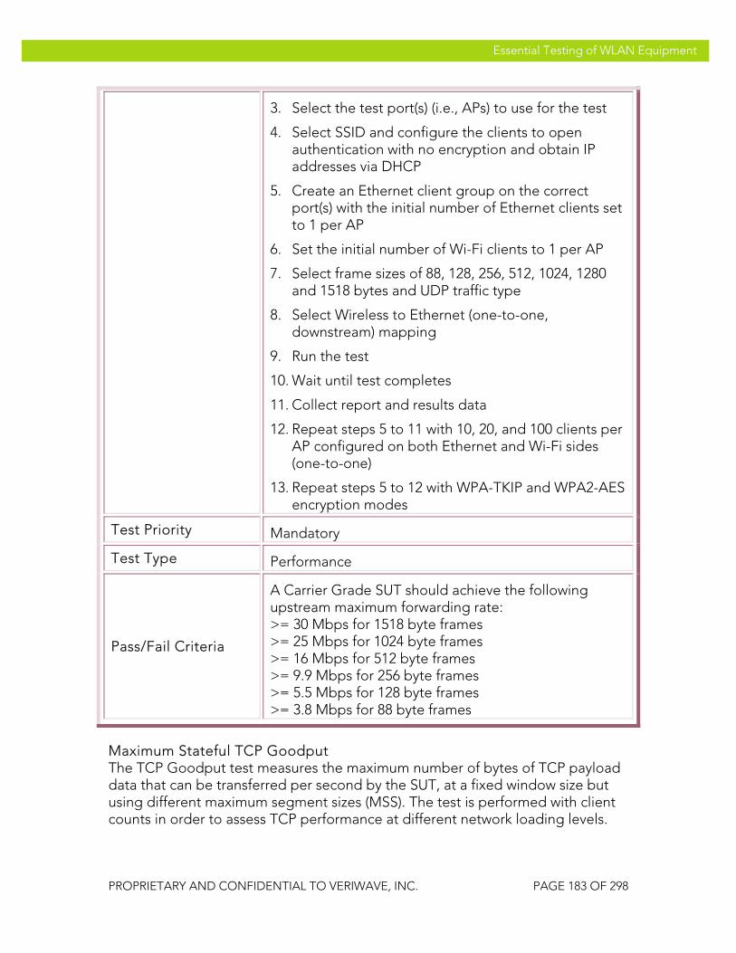
VeriWave, Inc. Essential Testing of WLAN Equipment
PROPRIETARY AND CONFIDENTIAL TO VERIWAVE, INC. PAGE 183 OF 298
Essential Testing of WLAN Equipment
3. Select the test port(s) (i.e., APs) to use for the test
4. Select SSID and configure the clients to open authentication with no encryption and obtain IP addresses via DHCP
5. Create an Ethernet client group on the correct port(s) with the initial number of Ethernet clients set to 1 per AP
6. Set the initial number of Wi-Fi clients to 1 per AP
7. Select frame sizes of 88, 128, 256, 512, 1024, 1280 and 1518 bytes and UDP traffic type
8. Select Wireless to Ethernet (one-to-one, downstream) mapping
9. Run the test
10. Wait until test completes
11. Collect report and results data
12. Repeat steps 5 to 11 with 10, 20, and 100 clients per AP configured on both Ethernet and Wi-Fi sides (one-to-one)
13. Repeat steps 5 to 12 with WPA-TKIP and WPA2-AES encryption modes
Test Priority Mandatory
Test Type Performance
Pass/Fail Criteria
A Carrier Grade SUT should achieve the following upstream maximum forwarding rate: >= 30 Mbps for 1518 byte frames >= 25 Mbps for 1024 byte frames >= 16 Mbps for 512 byte frames >= 9.9 Mbps for 256 byte frames >= 5.5 Mbps for 128 byte frames >= 3.8 Mbps for 88 byte frames
Maximum Stateful TCP Goodput The TCP Goodput test measures the maximum number of bytes of TCP payload data that can be transferred per second by the SUT, at a fixed window size but using different maximum segment sizes (MSS). The test is performed with client counts in order to assess TCP performance at different network loading levels.

VeriWave, Inc. Essential Testing of WLAN Equipment
PROPRIETARY AND CONFIDENTIAL TO VERIWAVE, INC. PAGE 184 OF 298
Essential Testing of WLAN Equipment
The TCP Goodput test expands on traditional MAC/IP (Layer 2 / Layer 3) throughput tests by measuring application throughput when using TCP over wireless LAN. For example, a frame that was successfully delivered at Layer 2 or Layer 3 may be dropped at Layer 4 because it was a duplicate or out-of-sequence TCP packet. Thus the TCP goodput (valid payload bytes per second) may be less than the Layer 2/3 throughput. As TCP is the most commonly observed WLAN traffic, the TCP Goodput test results enable users to determine the capacity of the SUT under real-world conditions..
The offered load is divided equally across the SUT ports; with multiple clients, each client presents the same load as all other clients. The TCP Goodput tests are conducted with a variety of maximum segment sizes, numbers of clients, security modes, operating bands and directions (i.e., upstream and downstream)..
PBTC-SP 050 Upstream_80211g_Max_TCP_Goodput
Title Measure maximum upstream TCP goodput
Purpose Measure the maximum upstream TCP goodput of the SUT for different frame sizes and numbers of clients
SUT Feature(s) Tested
Application-level data handling performance with TCP traffic
Requirement(s)
• WaveApps application running on host PC • WT-90 or WT-20 chassis with Wi-Fi WaveBlade(s)
and Ethernet WaveBlade(s) • SUT set up to support TCP traffic • DHCP enabled
Test Setup
• Configure the SUT with open-system authentication mode
• Set Basic Rate Set on SUT to 1Mbps, 2Mbps, 5.5Mbps, 6Mbps, 11Mbps, 12Mbps, 24Mbps
• Set client PHY rate to 54 Mb/s in IEEE 802.11g-only mode
• Set maximum number of sessions per client to 1 • Run test with no encryption, TKIP and AES-CCMP • Run test with TCP maximum segment sizes (MSS):
88, 216, 536, 984 and 1460 bytes • Run test with 1, 10, 20 and 100 clients per AP; for a
WLAN controller-based system, at least one test must be run with >1000 clients.
Procedure 1. Launch the WaveApps application

VeriWave, Inc. Essential Testing of WLAN Equipment
PROPRIETARY AND CONFIDENTIAL TO VERIWAVE, INC. PAGE 185 OF 298
Essential Testing of WLAN Equipment
2. Select the TCP Goodput Test under the TCP Test Suite
3. Select the test port(s) (i.e., APs) to use for the test
4. Select SSID and configure the clients to open authentication with no encryption and obtain IP addresses via DHCP
5. Create an Ethernet client group on the correct port(s) with the initial number of Ethernet clients set to 1 per AP
6. Set the initial number of Wi-Fi clients to 1 per AP
7. Select maximum segment sizes of 88, 216, 536, 984 and 1460 bytes
8. Set the number of sessions per client to 1 and the TCP window size to 65535
9. Select Wireless to Ethernet (one-to-one, upstream) mapping
10. Run the test
11. Wait until test completes
12. Collect report and results data
13. Repeat steps 5 to 11 with 10, 20, and 100 clients per AP configured on both Ethernet and Wi-Fi sides (one-to-one)
14. Repeat steps 5 to 12 with WPA-TKIP and WPA2-AES encryption modes
Test Priority Mandatory
Test Type Performance
Pass/Fail Criteria
A Carrier Grade SUT should achieve an upstream TCP Goodput of at least 80% of the theoretical max with 1 client: >= 23.7 Mbps for 1460 byte MSS >= 19.3 Mbps for 984 byte MSS >= 13.3 Mbps for 536 byte MSS >= 6.6 Mbps for 216 byte MSS >= 2.9 Mbps for 88 byte MSS
Multi-client results are generally expected to be lower than the above due to TCP windowing effects and

VeriWave, Inc. Essential Testing of WLAN Equipment
PROPRIETARY AND CONFIDENTIAL TO VERIWAVE, INC. PAGE 186 OF 298
Essential Testing of WLAN Equipment
contention.
PBTC-SP 051 Downstream_80211g_Max_TCP_Goodput
Title Measure maximum downstream TCP goodput
Purpose Measure the maximum downstream TCP goodput of the SUT for different frame sizes and numbers of clients
SUT Feature(s) Tested
Application-level data handling performance with TCP traffic
Requirement(s)
• WaveApps application running on host PC • WT-90 or WT-20 chassis with Wi-Fi WaveBlade(s)
and Ethernet WaveBlade(s) • SUT set up to support TCP traffic • DHCP enabled
Test Setup
• Configure the SUT with open-system authentication mode
• Set Basic Rate Set on SUT to 1Mbps, 2Mbps, 5.5Mbps, 6Mbps, 11Mbps, 12Mbps, 24Mbps
• Set client PHY rate to 54 Mb/s in IEEE 802.11g-only mode
• Set maximum number of sessions per client to 1 • Run test with no encryption, TKIP and AES-CCMP • Run test with TCP maximum segment sizes (MSS):
88, 216, 536, 984 and 1460 bytes • Run test with 1, 10, 20 and 100 clients per AP; for a
WLAN controller-based system, at least one test must be run with >1000 clients
Procedure
1. Launch the WaveApps application
2. Select the TCP Goodput Test under the TCP Test Suite
3. Select the test port(s) (i.e., APs) to use for the test
4. Select SSID and configure the clients to open authentication with no encryption and obtain IP addresses via DHCP
5. Create an Ethernet client group on the correct port(s) with the initial number of Ethernet clients set to 1 per AP

VeriWave, Inc. Essential Testing of WLAN Equipment
PROPRIETARY AND CONFIDENTIAL TO VERIWAVE, INC. PAGE 187 OF 298
Essential Testing of WLAN Equipment
6. Set the initial number of Wi-Fi clients to 1 per AP
7. Select maximum segment sizes of 88, 216, 536, 984 and 1460 bytes
8. Set the number of sessions per client to 1 and the TCP window size to 65535
9. Select Wireless to Ethernet (one-to-one, downstream) mapping
10. Run the test
11. Wait until test completes
12. Collect report and results data
13. Repeat steps 5 to 11 with 10, 20, and 100 clients per AP configured on both Ethernet and Wi-Fi sides (one-to-one)
14. Repeat steps 5 to 12 with WPA-TKIP and WPA2-AES encryption modes
Test Priority Mandatory
Test Type Performance
Pass/Fail Criteria
A Carrier Grade SUT should achieve an upstream TCP Goodput of at least 80% of the theoretical max with 1 client: >= 23.7 Mbps for 1460 byte MSS >= 19.3 Mbps for 984 byte MSS >= 13.3 Mbps for 536 byte MSS >= 6.6 Mbps for 216 byte MSS >= 2.9 Mbps for 88 byte MSS
Multi-client results are generally expected to be lower than the above due to TCP windowing effects and contention.
PBTC-SP 052 Upstream_80211a_Max_TCP_Goodput
Title Measure maximum upstream TCP goodput
Purpose
Measure the maximum upstream TCP goodput of the SUT for different frame sizes and numbers of clients. This test is only applicable to SUTs that contain IEEE 802.11a APs.
SUT Feature(s) Application-level data handling performance with TCP

VeriWave, Inc. Essential Testing of WLAN Equipment
PROPRIETARY AND CONFIDENTIAL TO VERIWAVE, INC. PAGE 188 OF 298
Essential Testing of WLAN Equipment
Tested traffic
Requirement(s)
• WaveApps application running on host PC • WT-90 or WT-20 chassis with Wi-Fi WaveBlade(s)
and Ethernet WaveBlade(s) • SUT set up to support TCP traffic • DHCP enabled
Test Setup
• Configure the SUT with open-system authentication mode
• Set Basic Rate Set on SUT to 6Mbps, 12Mbps, 24Mbps
• Set client PHY rate to 54 Mb/s in IEEE 802.11a mode
• Set maximum number of sessions per client to 1 • Run test with no encryption, TKIP and AES-CCMP • Run test with TCP maximum segment sizes (MSS):
88, 216, 536, 984 and 1460 bytes • Run test with 1, 10, 20 and 100 clients per AP; for a
WLAN controller-based system, at least one test must be run with >1000 clients.
Procedure
1. Launch the WaveApps application
2. Select the TCP Goodput Test under the TCP Test Suite
3. Select the test port(s) (i.e., APs) to use for the test
4. Select SSID and configure the clients to open authentication with no encryption and obtain IP addresses via DHCP
5. Create an Ethernet client group on the correct port(s) with the initial number of Ethernet clients set to 1 per AP
6. Set the initial number of Wi-Fi clients to 1 per AP
7. Select maximum segment sizes of 88, 216, 536, 984 and 1460 bytes
8. Set the number of sessions per client to 1 and the TCP window size to 65535
9. Select Wireless to Ethernet (one-to-one, upstream) mapping
10. Run the test
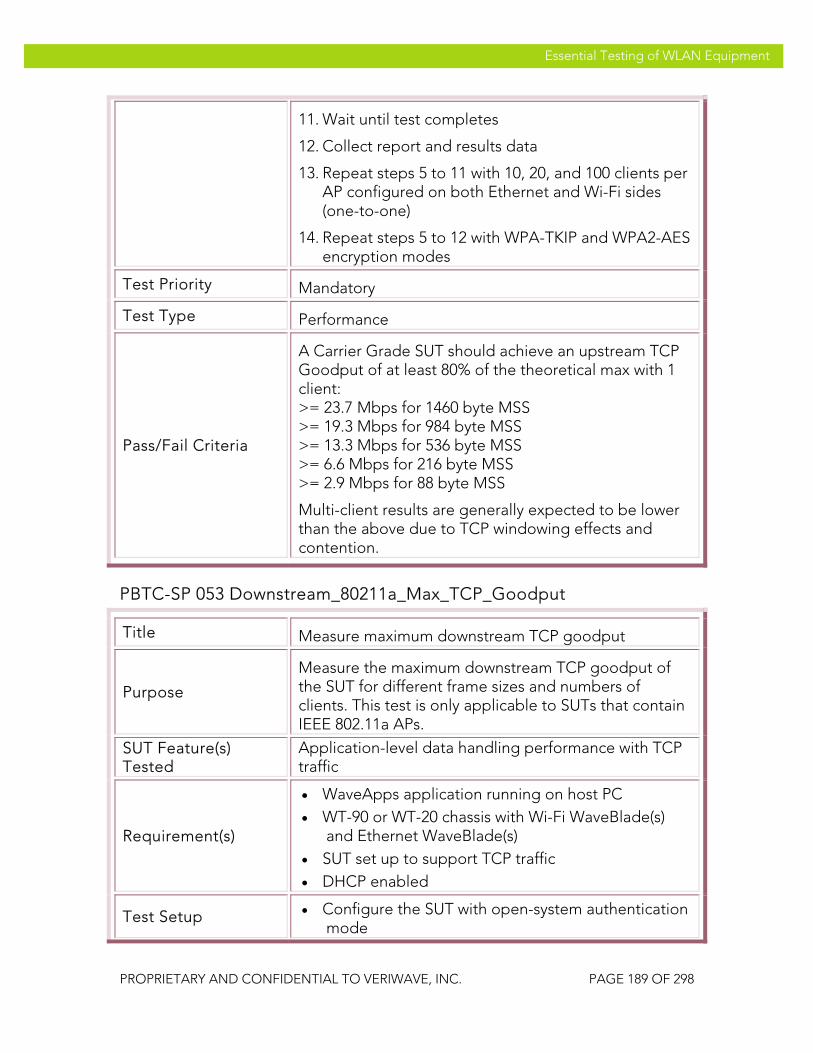
VeriWave, Inc. Essential Testing of WLAN Equipment
PROPRIETARY AND CONFIDENTIAL TO VERIWAVE, INC. PAGE 189 OF 298
Essential Testing of WLAN Equipment
11. Wait until test completes
12. Collect report and results data
13. Repeat steps 5 to 11 with 10, 20, and 100 clients per AP configured on both Ethernet and Wi-Fi sides (one-to-one)
14. Repeat steps 5 to 12 with WPA-TKIP and WPA2-AES encryption modes
Test Priority Mandatory
Test Type Performance
Pass/Fail Criteria
A Carrier Grade SUT should achieve an upstream TCP Goodput of at least 80% of the theoretical max with 1 client: >= 23.7 Mbps for 1460 byte MSS >= 19.3 Mbps for 984 byte MSS >= 13.3 Mbps for 536 byte MSS >= 6.6 Mbps for 216 byte MSS >= 2.9 Mbps for 88 byte MSS
Multi-client results are generally expected to be lower than the above due to TCP windowing effects and contention.
PBTC-SP 053 Downstream_80211a_Max_TCP_Goodput
Title Measure maximum downstream TCP goodput
Purpose
Measure the maximum downstream TCP goodput of the SUT for different frame sizes and numbers of clients. This test is only applicable to SUTs that contain IEEE 802.11a APs.
SUT Feature(s) Tested
Application-level data handling performance with TCP traffic
Requirement(s)
• WaveApps application running on host PC • WT-90 or WT-20 chassis with Wi-Fi WaveBlade(s)
and Ethernet WaveBlade(s) • SUT set up to support TCP traffic • DHCP enabled
Test Setup • Configure the SUT with open-system authentication mode

VeriWave, Inc. Essential Testing of WLAN Equipment
PROPRIETARY AND CONFIDENTIAL TO VERIWAVE, INC. PAGE 190 OF 298
Essential Testing of WLAN Equipment
• Set Basic Rate Set on SUT to 6Mbps, 12Mbps, 24Mbps
• Set client PHY rate to 54 Mb/s in IEEE 802.11a mode
• Set maximum number of sessions per client to 1 • Run test with no encryption, TKIP and AES-CCMP • Run test with TCP maximum segment sizes (MSS):
88, 216, 536, 984 and 1460 bytes • Run test with 1, 10, 20 and 100 clients per AP; for a
WLAN controller-based system, at least one test must be run with >1000 clients
Procedure
1. Launch the WaveApps application
2. Select the TCP Goodput Test under the TCP Test Suite
3. Select the test port(s) (i.e., APs) to use for the test
4. Select SSID and configure the clients to open authentication with no encryption and obtain IP addresses via DHCP
5. Create an Ethernet client group on the correct port(s) with the initial number of Ethernet clients set to 1 per AP
6. Set the initial number of Wi-Fi clients to 1 per AP
7. Select maximum segment sizes of 88, 216, 536, 984 and 1460 bytes
8. Set the number of sessions per client to 1 and the TCP window size to 65535
9. Select Wireless to Ethernet (one-to-one, downstream) mapping
10. Run the test
11. Wait until test completes
12. Collect report and results data
13. Repeat steps 5 to 11 with 10, 20, and 100 clients per AP configured on both Ethernet and Wi-Fi sides (one-to-one)
14. Repeat steps 5 to 12 with WPA-TKIP and WPA2-AES encryption modes

VeriWave, Inc. Essential Testing of WLAN Equipment
PROPRIETARY AND CONFIDENTIAL TO VERIWAVE, INC. PAGE 191 OF 298
Essential Testing of WLAN Equipment
Test Priority Mandatory
Test Type Performance
Pass/Fail Criteria
A Carrier Grade SUT should achieve an upstream TCP Goodput of at least 80% of the theoretical max with 1 client: >= 23.7 Mbps for 1460 byte MSS >= 19.3 Mbps for 984 byte MSS >= 13.3 Mbps for 536 byte MSS >= 6.6 Mbps for 216 byte MSS >= 2.9 Mbps for 88 byte MSS
Multi-client results are generally expected to be lower than the above due to TCP windowing effects and contention.
Roaming Performance The roaming performance tests measure the roaming delay, roaming failures and packet loss when the SUT is stressed with mobile clients transitioning between APs at a specified rate and security setup. The roaming measurement results therefore quantify the SUT’s ability to support carrier-class roaming traffic loads, such as many VoIP handsets. The roaming clients continuously perform data transfers as they transition between APs in order to ensure a realistic traffic loading scenario. The test is conducted with a variety of roaming rates (i.e., roaming loads), numbers of clients, security modes and operating bands. A baseline roaming measurement is taken, after which variations are tested. A set of “accelerated” measurements are also specified. These measurements test the efficacy of various roaming speedup mechanisms – proactive key caching, preauthentication, and PMKID caching – that may be implemented in the SUT. Note that these tests are only valid if the SUT actually implements one or more of the specified speedup mechanisms.
PBTC-SP 070 Roaming_Delay_80211g_Baseline
Title Establish baseline roaming delay, failures, and loss ratio
Purpose
Measures the minimum, maximum and average roaming delay, total number of roaming failures, and average packets lost per roam for the SUT when configured in IEEE 802.11g mode, and stressed with a

VeriWave, Inc. Essential Testing of WLAN Equipment
PROPRIETARY AND CONFIDENTIAL TO VERIWAVE, INC. PAGE 192 OF 298
Essential Testing of WLAN Equipment
roaming rate of 0.1 roams per second with 1 client using open security and no DHCP.
SUT Feature(s) Tested
Basic roaming support and performance
Requirement(s)
• WaveApps application running on host PC • WT-90 or WT-20 chassis with Wi-Fi WaveBlade(s)
and Ethernet WaveBlade(s) • SUT set up to support UDP traffic • DHCP disabled (static IP addressing)
Test Setup
• Configure the SUT with open-system authentication mode
• Configure static IP subnets in the SUT and related network
• Set Basic Rate Set on SUT to 1Mbps, 2Mbps, 5.5Mbps, 6Mbps, 11Mbps, 12Mbps, 24Mbps
• Set client PHY rate to 54 Mb/s in IEEE 802.11g mode
• Set number of WLAN clients to 1 • Set security to none (open authentication, no
encryption) • Set roaming rate to 0.1 roams/second
Procedure
1. Launch the WaveApps application
2. Select the Roaming Benchmark Test under the WLAN Roaming Test Suite
3. Select the test ports (i.e., APs) to use for the test (a minimum of 2 ports is required)
4. Select SSID and configure 1 client for open authentication with no encryption, using a fixed IP address
5. Create an Ethernet client group on the correct port
6. Set the roam sequence to roam the client uniformly across all test ports
7. Set the roaming rate to 0.1 roams/second (for the entire SUT) and the test duration to 600 seconds (i.e., 60 roams)
8. Set the data traffic flow from Ethernet to wireless, with a frame size of 256 bytes and a flow rate of 100 pps (per client)

VeriWave, Inc. Essential Testing of WLAN Equipment
PROPRIETARY AND CONFIDENTIAL TO VERIWAVE, INC. PAGE 193 OF 298
Essential Testing of WLAN Equipment
9. Run the test
10. Wait until test completes
11. Collect report and results data
Test Priority Mandatory
Test Type Performance
Pass/Fail Criteria
A Carrier Grade SUT should complete this test with zero failed roams, packet loss ratio of under 1%, and an average roam delay of 10 milliseconds or less. The maximum roam delay should not exceed 50 milliseconds.
PBTC-SP 071 Roaming_Delay_80211a_Baseline
Title Establish baseline roaming delay, failures, and loss ratio
Purpose
Measures the minimum, maximum and average roaming delay, total number of roaming failures, and average packets lost per roam for the SUT when configured in IEEE 802.11g mode, and stressed with a roaming rate of 0.1 roams per second with 1 client using open security and no DHCP. This test is only applicable to SUTs that contain IEEE 802.11a APs.
SUT Feature(s) Tested
Basic roaming support and performance
Requirement(s)
• WaveApps application running on host PC • WT-90 or WT-20 chassis with Wi-Fi WaveBlade(s)
and Ethernet WaveBlade(s) • SUT set up to support UDP traffic • DHCP disabled (static IP addressing)
Test Setup
• Configure the SUT with open-system authentication mode
• Configure static IP subnets in the SUT and related network
• Set Basic Rate Set on SUT to 6Mbps, 12Mbps, 24Mbps
• Set client PHY rate to 54 Mb/s in IEEE 802.11a mode

VeriWave, Inc. Essential Testing of WLAN Equipment
PROPRIETARY AND CONFIDENTIAL TO VERIWAVE, INC. PAGE 194 OF 298
Essential Testing of WLAN Equipment
• Set number of WLAN clients to 1 • Set security to none (open authentication, no
encryption) • Set roaming rate to 0.1 roams/second
Procedure
1. Launch the WaveApps application
2. Select the Roaming Benchmark Test under the WLAN Roaming Test Suite
3. Select the test ports (i.e., APs) to use for the test (a minimum of 2 ports is required)
4. Select SSID and configure 1 client for open authentication with no encryption, using a fixed IP address
5. Create an Ethernet client group on the correct port
6. Set the roam sequence to roam the client uniformly across all test ports
7. Set the roaming rate to 0.1 roams/second (for the entire SUT) and the test duration to 600 seconds (i.e., 60 roams)
8. Set the data traffic flow from Ethernet to wireless, with a frame size of 256 bytes and a flow rate of 100 pps (per client)
9. Run the test
10. Wait until test completes
11. Collect report and results data
Test Priority Mandatory
Test Type Performance
Pass/Fail Criteria
A Carrier Grade SUT should complete this test with zero failed roams, packet loss ratio of under 1%, and an average roam delay of 10 milliseconds or less. The maximum roam delay should not exceed 50 milliseconds.
PBTC-SP 072 Roaming_Delay_80211g_Secure
Title Determine variation of roaming delay, failures, and loss ratio with security modes and client counts

VeriWave, Inc. Essential Testing of WLAN Equipment
PROPRIETARY AND CONFIDENTIAL TO VERIWAVE, INC. PAGE 195 OF 298
Essential Testing of WLAN Equipment
Purpose
Measures the minimum, maximum and average roaming delay, total number of roaming failures, and average packets lost per roam for the SUT when configured in IEEE 802.11g mode, and stressed with different numbers of clients, security modes and rates.
SUT Feature(s) Tested
Roaming scalability with security
Requirement(s)
• WaveApps application running on host PC • WT-90 or WT-20 chassis with Wi-Fi WaveBlade(s)
and Ethernet WaveBlade(s) • SUT set up to support UDP traffic • DHCP disabled (static IP addressing)
Test Setup
• Configure the SUT with security modes to: WEP-128, WPA-PSK, WPA2-PSK
• Configure static IP subnets in the SUT and related network
• Set Basic Rate Set on SUT to 1Mbps, 2Mbps, 5.5Mbps, 6Mbps, 11Mbps, 12Mbps, 24Mbps
• Set client PHY rate to 54 Mb/s in IEEE 802.11g mode
• Set WLAN client counts to: 10, 50, 100 and 500 per SUT
• Set roaming rates to: 0.5, 1, and 5 roams/second
Procedure
1. Launch the WaveApps application
2. Select the Roaming Benchmark Test under the WLAN Roaming Test Suite
3. Select the test ports (i.e., APs) to use for the test (a minimum of 2 ports is required)
4. Set the initial number of clients to 10
5. Select SSID and initially configure the clients for WEP-128
6. Create an Ethernet client group on the correct port
7. Set the roam sequence to roam all clients uniformly across all test ports, with a uniform initial client distribution
8. Set the initial roaming rate to 0.5 roams/second (for the entire SUT) and the test duration to 300 seconds (i.e., 150 roams)

VeriWave, Inc. Essential Testing of WLAN Equipment
PROPRIETARY AND CONFIDENTIAL TO VERIWAVE, INC. PAGE 196 OF 298
Essential Testing of WLAN Equipment
9. Set the data traffic flow from Ethernet to wireless, with a frame size of 256 bytes and a flow rate of 100 pps (per client)
10. Run the test
11. Wait until test completes
12. Collect reports and results data
13. Repeat steps 4 to 12 with 50, 100 and 500 clients
14. Repeat steps 4 to 13 with WPA-PSK, WPA2-PSK security modes
15. Repeat steps 4 to 14 with 1 and 5 roams/second
Test Priority Mandatory
Test Type Performance
Pass/Fail Criteria
A Carrier Grade SUT should complete this test with zero failed roams, packet loss ratio of under 10%, and an average roam delay of 25 milliseconds or less. The maximum roam delay should not exceed 200 milliseconds for any client during any run.
PBTC-SP 073 Roaming_Delay_80211a_Secure
Title Determine variation of roaming delay, failures, and loss ratio with security modes and client counts
Purpose
Measures the minimum, maximum and average roaming delay, total number of roaming failures, and average packets lost per roam for the SUT when configured in IEEE 802.11a mode, and stressed with different numbers of clients, security modes and rates. This test is only applicable to SUTs that contain IEEE 802.11a APs.
SUT Feature(s) Tested
Roaming scalability with security
Requirement(s)
• WaveApps application running on host PC • WT-90 or WT-20 chassis with Wi-Fi WaveBlade(s)
and Ethernet WaveBlade(s) • SUT set up to support UDP traffic • DHCP disabled (static IP addressing)

VeriWave, Inc. Essential Testing of WLAN Equipment
PROPRIETARY AND CONFIDENTIAL TO VERIWAVE, INC. PAGE 197 OF 298
Essential Testing of WLAN Equipment
Test Setup
• Configure the SUT with security modes to: WEP-128, WPA-PSK, WPA2-PSK
• Configure static IP subnets in the SUT and related network
• Set Basic Rate Set on SUT to 6Mbps, 12Mbps, 24Mbps
• Set client PHY rate to 54 Mb/s in IEEE 802.11a mode
• Set WLAN client counts to: 10, 50, 100 and 500 per SUT
• Set roaming rates to: 0.5, 1, and 5 roams/second
Procedure
1. Launch the WaveApps application
2. Select the Roaming Benchmark Test under the WLAN Roaming Test Suite
3. Select the test ports (i.e., APs) to use for the test (a minimum of 2 ports is required)
4. Set the initial number of clients to 10
5. Select SSID and initially configure the clients for WEP-128
6. Create an Ethernet client group on the correct port
7. Set the roam sequence to roam all clients uniformly across all test ports, with a uniform initial client distribution
8. Set the initial roaming rate to 0.5 roams/second (for the entire SUT) and the test duration to 300 seconds (i.e., 150 roams)
9. Set the data traffic flow from Ethernet to wireless, with a frame size of 256 bytes and a flow rate of 100 pps (per client)
10. Run the test
11. Wait until the test completes
12. Collect reports and results data
13. Repeat steps 4 to 12 with 50, 100 and 500 clients
14. Repeat steps 4 to 13 with WPA-PSK, WPA2-PSK security modes
15. Repeat steps 4 to 14 with 1 and 5 roams/second

VeriWave, Inc. Essential Testing of WLAN Equipment
PROPRIETARY AND CONFIDENTIAL TO VERIWAVE, INC. PAGE 198 OF 298
Essential Testing of WLAN Equipment
Test Priority Mandatory
Test Type Performance
Pass/Fail Criteria
A Carrier Grade SUT should complete this test with zero failed roams, packet loss ratio of under 10%, and an average roam delay of 25 milliseconds or less. The maximum roam delay should not exceed 200 milliseconds for any client during any run.
PBTC-SP 074 Roaming_Delay_80211g_DHCP
Title Determine variation of roaming delay, failures, and loss ratio with security modes and client counts when using DHCP
Purpose
Measures the minimum, maximum and average roaming delay, total number of roaming failures, and average packets lost per roam for the SUT when configured in IEEE 802.11g mode with DHCP, and stressed with different numbers of clients and security modes.
SUT Feature(s) Tested
Roaming scalability with DHCP support
Requirement(s)
• WaveApps application running on host PC • WT-90 or WT-20 chassis with Wi-Fi WaveBlade(s)
and Ethernet WaveBlade(s) • SUT set up to support UDP traffic • DHCP server
Test Setup
• Configure the SUT with security modes to: WPA-PSK, WPA2-PSK
• Configure WLAN and Ethernet clients to use DHCP • Set Basic Rate Set on SUT to 1Mbps, 2Mbps,
5.5Mbps, 6Mbps, 11Mbps, 12Mbps, 24Mbps • Set client PHY rate to 54 Mb/s in IEEE 802.11g
mode • Set WLAN client counts to: 10, 50, 100 and 500 per
SUT (Note: for 500 clients, subnet collision must be checked)
• Set roaming rates to: 0.5, 1, and 4 roams/second
Procedure 1. Launch the WaveApps application

VeriWave, Inc. Essential Testing of WLAN Equipment
PROPRIETARY AND CONFIDENTIAL TO VERIWAVE, INC. PAGE 199 OF 298
Essential Testing of WLAN Equipment
2. Select the Roaming Benchmark Test under the WLAN Roaming Test Suite
3. Select the test ports (i.e., APs) to use for the test (a minimum of 2 ports is required)
4. Set the initial number of clients to 10
5. Select SSID and initially configure the clients for WPA-PSK and DHCP
6. Create an Ethernet client group on the correct port
7. Set the roam sequence to roam all clients uniformly across all test ports, with a uniform initial client distribution
8. Set the initial roaming rate to 0.5 roams/second (for the entire SUT) and the test duration to 300 seconds (i.e., 150 roams)
9. Set the data traffic flow from Ethernet to wireless, with a frame size of 256 bytes and a flow rate of 100 pps (per client)
10. Run the test
11. Wait until the test completes
12. Collect reports and results data
13. Repeat steps 4 to 12 with 50, 100 and 500 clients
14. Repeat steps 4 to 13 with WPA2-PSK security modes
15. Repeat steps 4 to 14 with 1 and 4 roams/second
Test Priority Mandatory
Test Type Performance
Pass/Fail Criteria
A Carrier Grade SUT should complete this test with zero failed roams, packet loss ratio of under 10%, and an average roam delay of 25 milliseconds or less. The maximum roam delay should not exceed 250 milliseconds for any client during any run.
PBTC-SP 075 Roaming_Delay_80211a_DHCP
Title Determine variation of roaming delay, failures, and loss ratio with security modes and client counts when using

VeriWave, Inc. Essential Testing of WLAN Equipment
PROPRIETARY AND CONFIDENTIAL TO VERIWAVE, INC. PAGE 200 OF 298
Essential Testing of WLAN Equipment
DHCP
Purpose
Measures the minimum, maximum and average roaming delay, total number of roaming failures, and average packets lost per roam for the SUT when configured in IEEE 802.11a mode with DHCP, and stressed with different numbers of clients and security modes
SUT Feature(s) Tested
Roaming scalability with DHCP support
Requirement(s)
• WaveApps application running on host PC • WT-90 or WT-20 chassis with Wi-Fi WaveBlade(s)
and Ethernet WaveBlade(s) • SUT set up to support UDP traffic • DHCP server
Test Setup
• Configure the SUT with security modes to: WPA-PSK, WPA2-PSK
• Configure WLAN and Ethernet clients to use DHCP • Set Basic Rate Set on SUT to 6Mbps, 12Mbps,
24Mbps • Set client PHY rate to 54 Mb/s in IEEE 802.11a
mode • Set WLAN client counts to: 10, 50, 100 and 500 per
SUT (Note: for 500 clients, subnet collision must be checked)
• Set roaming rates to: 0.5, 1, and 4 roams/second
Procedure
1. Launch the WaveApps application
2. Select the Roaming Benchmark Test under the WLAN Roaming Test Suite
3. Select the test ports (i.e., APs) to use for the test (a minimum of 2 ports is required)
4. Set the initial number of clients to 10
5. Select SSID and initially configure the clients for WPA-PSK and DHCP
6. Create an Ethernet client group on the correct port
7. Set the roam sequence to roam all clients uniformly across all test ports, with a uniform initial client distribution

VeriWave, Inc. Essential Testing of WLAN Equipment
PROPRIETARY AND CONFIDENTIAL TO VERIWAVE, INC. PAGE 201 OF 298
Essential Testing of WLAN Equipment
8. Set the initial roaming rate to 0.5 roams/second (for the entire SUT) and the test duration to 300 seconds (i.e., 150 roams)
9. Set the data traffic flow from Ethernet to wireless, with a frame size of 256 bytes and a flow rate of 100 pps (per client)
10. Run the test
11. Wait until the test completes
12. Collect reports and results data
13. Repeat steps 4 to 12 with 50, 100 and 500 clients
14. Repeat steps 4 to 13 with WPA2-PSK security modes
15. Repeat steps 4 to 14 with 1 and 4 roams/second
Test Priority Mandatory
Test Type Performance
Pass/Fail Criteria
A Carrier Grade SUT should complete this test with zero failed roams, packet loss ratio of under 10%, and an average roam delay of 25 milliseconds or less. The maximum roam delay should not exceed 250 milliseconds for any client during any run.
PBTC-SP 076 Roaming_Delay_80211g_MultiSSID
Title Determine variation of roaming delay, failures, and loss ratio with multiple concurrently active security modes
Purpose
Measures the minimum, maximum and average roaming delay, total number of roaming failures, and average packets lost per roam for the SUT when configured in IEEE 802.11g mode and stressed with different numbers of clients and security modes. Multiple SSIDs associated with different security modes are configured to represent actual conditions in a live network.
SUT Feature(s) Tested
Sustained performance with multiple overlay WLANs with different traffic types
Requirement(s) • WaveApps application running on host PC • WT-90 or WT-20 chassis with Wi-Fi WaveBlade(s)

VeriWave, Inc. Essential Testing of WLAN Equipment
PROPRIETARY AND CONFIDENTIAL TO VERIWAVE, INC. PAGE 202 OF 298
Essential Testing of WLAN Equipment
and Ethernet WaveBlade(s) • SUT set up to support UDP traffic • DHCP server
Test Setup
• Configure the SUT with 2 different SSIDs supporting combinations of different security modes matching: Open (no security), WEP-128, WPA-PSK, WPA2-PSK
• Configure static IP subnets in the SUT and related network
• Set Basic Rate Set on SUT to 1Mbps, 2Mbps, 5.5Mbps, 6Mbps, 11Mbps, 12Mbps, 24Mbps
• Set client PHY rate to 54 Mb/s in IEEE 802.11g mode
• Set total WLAN client counts to: 10, 50, 100 and 500 per SUT (Note: for 500 clients, subnet collision must be checked)
• Set roaming rates to: 0.5, 1, and 4 roams/second • Set proactive key caching, preauthentication and
PMKID caching during different trials
Procedure
1. Launch the WaveApps application
2. Select the Roaming Benchmark Test under the WLAN Roaming Test Suite
3. Select the test ports (i.e., APs) to use for the test (a minimum of 2 ports is required)
4. Set the initial number of clients to 10 in 2 groups of 5 each
5. Configure two different SSIDs in the SUT, referred to here as “SSID-A” and “SSID-B”; set up IP subnets and VLANs as appropriate to support these two SSIDs
6. Set SSID-A in the SUT to initially support Open, configure one client group to match this SSID and security, and configure a fixed IP (per SUT requirements) for this group
7. Set SSID-B in the SUT to initially support WPA-PSK, configure the second client group to match this SSID and security, and configure a fixed IP (per SUT requirements) for this group
8. Create an Ethernet client group on the correct port
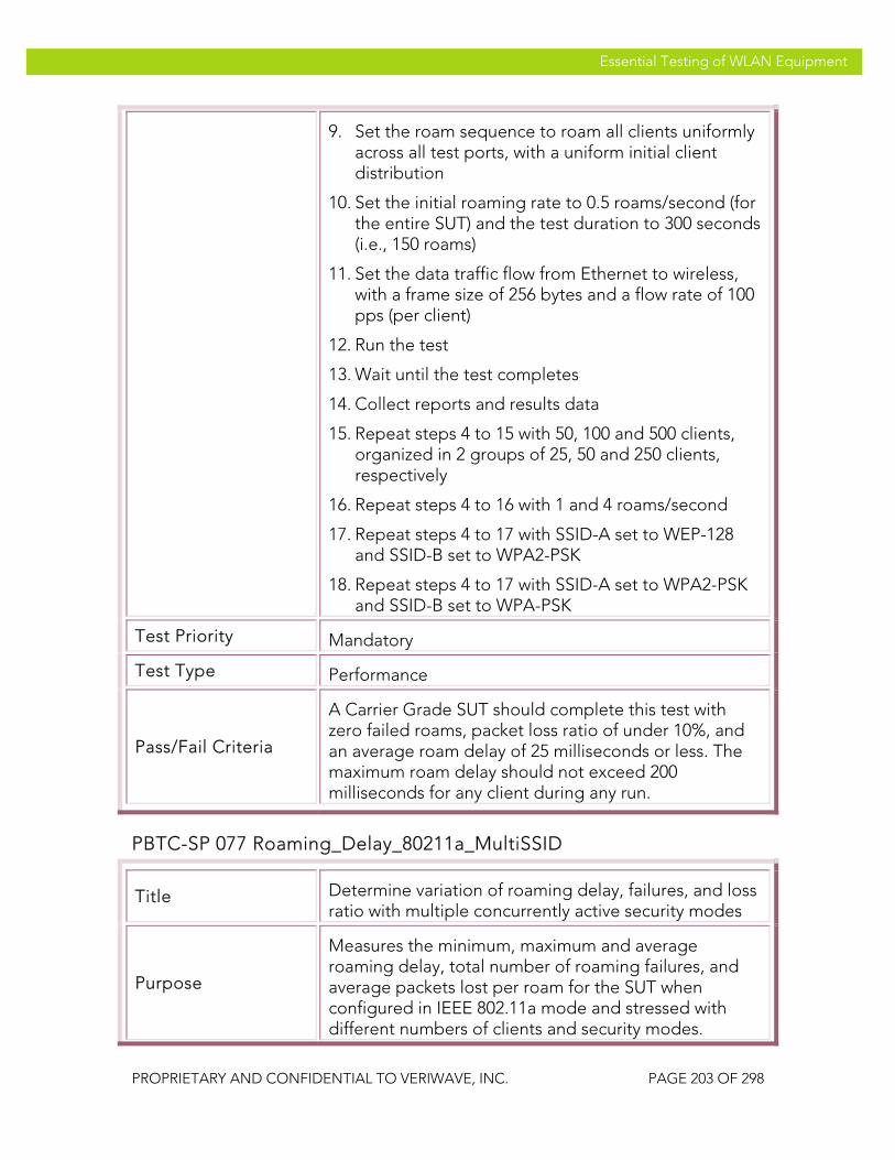
VeriWave, Inc. Essential Testing of WLAN Equipment
PROPRIETARY AND CONFIDENTIAL TO VERIWAVE, INC. PAGE 203 OF 298
Essential Testing of WLAN Equipment
9. Set the roam sequence to roam all clients uniformly across all test ports, with a uniform initial client distribution
10. Set the initial roaming rate to 0.5 roams/second (for the entire SUT) and the test duration to 300 seconds (i.e., 150 roams)
11. Set the data traffic flow from Ethernet to wireless, with a frame size of 256 bytes and a flow rate of 100 pps (per client)
12. Run the test
13. Wait until the test completes
14. Collect reports and results data
15. Repeat steps 4 to 15 with 50, 100 and 500 clients, organized in 2 groups of 25, 50 and 250 clients, respectively
16. Repeat steps 4 to 16 with 1 and 4 roams/second
17. Repeat steps 4 to 17 with SSID-A set to WEP-128 and SSID-B set to WPA2-PSK
18. Repeat steps 4 to 17 with SSID-A set to WPA2-PSK and SSID-B set to WPA-PSK
Test Priority Mandatory
Test Type Performance
Pass/Fail Criteria
A Carrier Grade SUT should complete this test with zero failed roams, packet loss ratio of under 10%, and an average roam delay of 25 milliseconds or less. The maximum roam delay should not exceed 200 milliseconds for any client during any run.
PBTC-SP 077 Roaming_Delay_80211a_MultiSSID
Title Determine variation of roaming delay, failures, and loss ratio with multiple concurrently active security modes
Purpose
Measures the minimum, maximum and average roaming delay, total number of roaming failures, and average packets lost per roam for the SUT when configured in IEEE 802.11a mode and stressed with different numbers of clients and security modes.
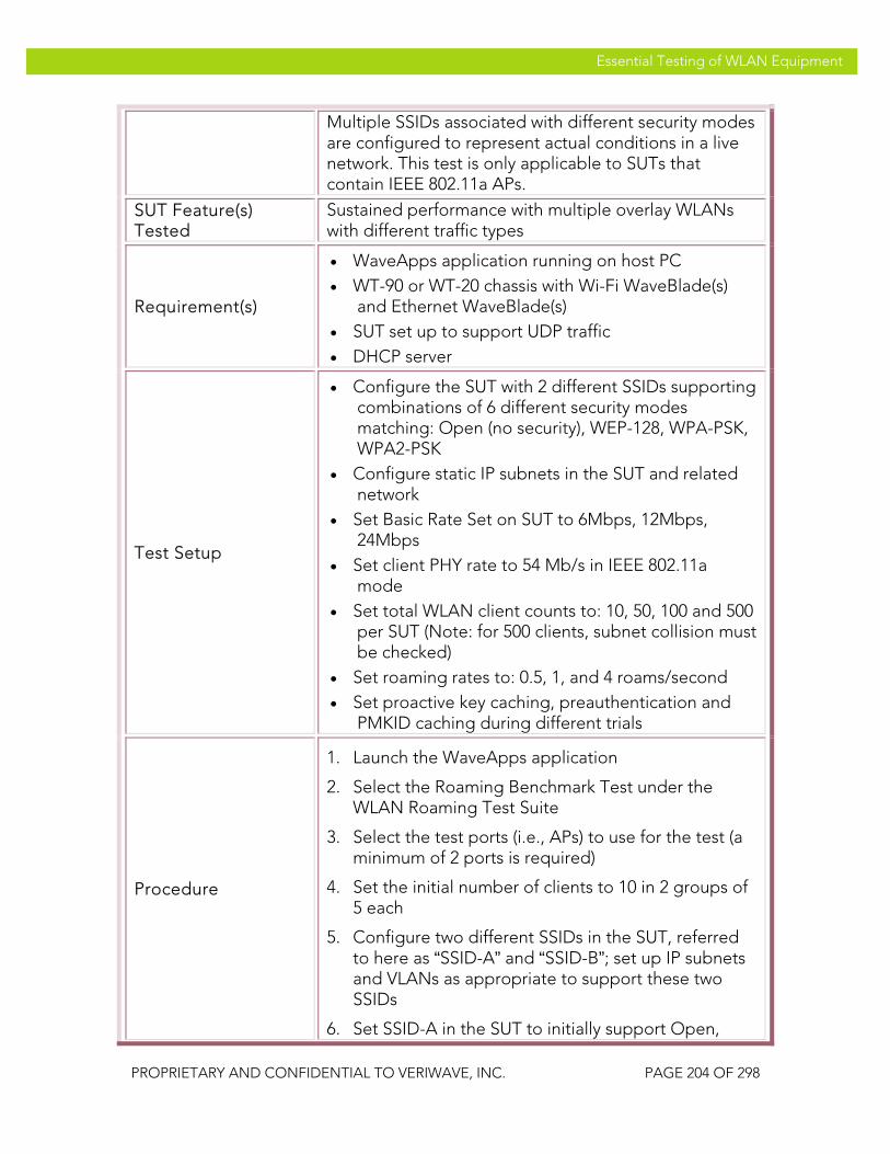
VeriWave, Inc. Essential Testing of WLAN Equipment
PROPRIETARY AND CONFIDENTIAL TO VERIWAVE, INC. PAGE 204 OF 298
Essential Testing of WLAN Equipment
Multiple SSIDs associated with different security modes are configured to represent actual conditions in a live network. This test is only applicable to SUTs that contain IEEE 802.11a APs.
SUT Feature(s) Tested
Sustained performance with multiple overlay WLANs with different traffic types
Requirement(s)
• WaveApps application running on host PC • WT-90 or WT-20 chassis with Wi-Fi WaveBlade(s)
and Ethernet WaveBlade(s) • SUT set up to support UDP traffic • DHCP server
Test Setup
• Configure the SUT with 2 different SSIDs supporting combinations of 6 different security modes matching: Open (no security), WEP-128, WPA-PSK, WPA2-PSK
• Configure static IP subnets in the SUT and related network
• Set Basic Rate Set on SUT to 6Mbps, 12Mbps, 24Mbps
• Set client PHY rate to 54 Mb/s in IEEE 802.11a mode
• Set total WLAN client counts to: 10, 50, 100 and 500 per SUT (Note: for 500 clients, subnet collision must be checked)
• Set roaming rates to: 0.5, 1, and 4 roams/second • Set proactive key caching, preauthentication and
PMKID caching during different trials
Procedure
1. Launch the WaveApps application
2. Select the Roaming Benchmark Test under the WLAN Roaming Test Suite
3. Select the test ports (i.e., APs) to use for the test (a minimum of 2 ports is required)
4. Set the initial number of clients to 10 in 2 groups of 5 each
5. Configure two different SSIDs in the SUT, referred to here as “SSID-A” and “SSID-B”; set up IP subnets and VLANs as appropriate to support these two SSIDs
6. Set SSID-A in the SUT to initially support Open,
VeriWave, Inc. Essential Testing of WLAN Equipment
PROPRIETARY AND CONFIDENTIAL TO VERIWAVE, INC. PAGE 205 OF 298
Essential Testing of WLAN Equipment
configure one client group to match this SSID and security, and configure a fixed IP (per SUT requirements) for this group
7. Set SSID-B in the SUT to initially support WPA-PSK, configure the second client group to match this SSID and security, and configure a fixed IP (per SUT requirements) for this group
8. Create an Ethernet client group on the correct port
9. Set the roam sequence to roam all clients uniformly across all test ports, with a uniform initial client distribution
10. Set the initial roaming rate to 0.5 roams/second (for the entire SUT) and the test duration to 300 seconds (i.e., 150 roams)
11. Set the data traffic flow from Ethernet to wireless, with a frame size of 256 bytes and a flow rate of 100 pps (per client)
12. Run the test
13. Wait until the test completes
14. Collect reports and results data
15. Repeat steps 4 to 15 with 50, 100 and 500 clients, organized in 2 groups of 25, 50 and 250 clients, respectively
16. Repeat steps 4 to 16 with 1 and 4 roams/second
17. Repeat steps 4 to 17 with SSID-A set to WEP-128 and SSID-B set to WPA2-PSK
18. Repeat steps 4 to 17 with SSID-A set to WPA2-PSK and SSID-B set to WPA-PSK
Test Priority Mandatory
Test Type Performance
Pass/Fail Criteria
A Carrier Grade SUT should complete this test with zero failed roams, packet loss ratio of under 10%, and an average roam delay of 25 milliseconds or less. The maximum roam delay should not exceed 200 milliseconds for any client during any run.

VeriWave, Inc. Essential Testing of WLAN Equipment
PROPRIETARY AND CONFIDENTIAL TO VERIWAVE, INC. PAGE 206 OF 298
Essential Testing of WLAN Equipment
Mesh Per-Hop and Aggregate Throughput The following mesh throughput tests measure the maximum rate at which the mesh SUT can forward packets without loss, both on a per-hop basis (i.e., individually for each mesh AP) and an aggregate basis (i.e., collectively for all mesh APs taken as a whole). These throughput tests are key measurements of the performance of a mesh SUT under real-world conditions. For example, even small amounts of packet loss can cause TCP sessions to ratchet down their goodput considerably, and sometimes even enter slow-start mode (with very low transfer rates). These tests are hence indicative of how much traffic and how many users the SUT can support, and also of internal issues with the SUT forwarding datapaths and routing algorithms.
Also see the section dealing with tests on interference effects. Note that interference effects are not applied to the tests in this section.
The mesh throughput tests are conducted with different frame sizes, numbers of clients, security modes, and directions (i.e., upstream, downstream and bi-directional). They are also carried out with different traffic types (i.e., UDP and TCP).
Note that the test cases must be performed in the appropriate band used for client and subscriber access to the SUT. In many cases, this is the IEEE 802.11b/g channel set (2.4 GHz).
PBTC-SP 100 Upstream_UDP_Per-Hop_Throughput
Title Measure upstream UDP mesh throughput per-hop
Purpose
Measure the upstream UDP per-hop mesh throughput that can be achieved by the SUT; this can be used to determine the sustainable uplink bandwidth per subscriber.
SUT Feature(s) Tested
Maximum per-hop mesh data forwarding capacity, mesh routing performance
Requirement(s)
• WaveApps application running on host PC • WT-90 or WT-20 chassis with Wi-Fi WaveBlade(s)
and Ethernet WaveBlade(s) • Mesh SUT set up to support UDP traffic • DHCP enabled
Test Setup
• Configure the SUT in mesh configuration with at least two access points
• Configure the SUT with open authentication • Set Basic Rate Set on SUT to 1Mbps, 2Mbps,
5.5Mbps, 6Mbps, 11Mbps, 12Mbps and 24Mbps (IEEE 802.11g mode) or 6Mbps, 12Mbps and

VeriWave, Inc. Essential Testing of WLAN Equipment
PROPRIETARY AND CONFIDENTIAL TO VERIWAVE, INC. PAGE 207 OF 298
Essential Testing of WLAN Equipment
24Mbps (IEEE 802.11a mode, if applicable) • Set client PHY rate to 54 Mb/s • Run test with no cipher, WPA-TKIP and WPA2-AES • Run test with frame sizes: 88, 128, 256, 512, 1024,
1280 and 1518 bytes • Run test with 1, 10, 20 and 100 clients per mesh AP;
for a WLAN controller-based system, at least one test must be run with >1000 clients
Procedure
1. Launch the WaveApps application
2. Select the Mesh Per-Hop Throughput Test under the Wireless Mesh Test Suite
3. Select the test port(s) (i.e., APs) to use for the test and configure into IEEE 802.11g or IEEE 802.11a mode as required
4. Select SSID and configure the clients to open authentication with no encryption and obtain IP addresses via DHCP
5. Create an Ethernet client group on the correct port(s) with the initial number of Ethernet clients set to 1 per AP
6. Set the initial number of Wi-Fi clients to 1 per AP
7. Select frame sizes of 88, 128, 256, 512, 1024, 1280 and 1518 bytes and UDP traffic type
8. Select Mesh Hops to Mesh Gateway (upstream) mapping
9. Run the test
10. Wait until test completes
11. Collect report and results data
12. Repeat steps 5 to 11 with 10, 20, and 100 clients per mesh AP configured on both Ethernet and Wi-Fi sides (one-to-one)
13. Repeat steps 5 to 12 with WPA-TKIP and WPA2-AES encryption modes
Test Priority Mandatory for Mesh SUTs
Test Type Performance
Pass/Fail Criteria A Carrier Grade mesh SUT should achieve an upstream
VeriWave, Inc. Essential Testing of WLAN Equipment
PROPRIETARY AND CONFIDENTIAL TO VERIWAVE, INC. PAGE 208 OF 298
Essential Testing of WLAN Equipment
throughput per hop that is at least 50% of the theoretical maximum for the channel: >= 15 Mbps for 1518 byte frames >= 12.5 Mbps for 1024 byte frames >= 8 Mbps for 512 byte frames >= 4.5 Mbps for 256 byte frames >= 2.75 Mbps for 128 byte frames >= 1.9 Mbps for 88 byte frames
PBTC-SP 101 Downstream_UDP_Per-Hop_Throughput
Title Measure downstream UDP mesh throughput per-hop
Purpose
Measure the downstream UDP per-hop mesh throughput that can be achieved by the SUT; this can be used to determine the sustainable downlink capacity of the mesh system as seen by each subscriber.
SUT Feature(s) Tested
Maximum per-hop mesh data forwarding capacity, mesh routing performance
Requirement(s)
• WaveApps application running on host PC • WT-90 or WT-20 chassis with Wi-Fi WaveBlade(s)
and Ethernet WaveBlade(s) • Mesh SUT set up to support UDP traffic • DHCP enabled
Test Setup
• Configure the SUT in mesh configuration with at least two access points
• Configure the SUT with open authentication • Set Basic Rate Set on SUT to 1Mbps, 2Mbps,
5.5Mbps, 6Mbps, 11Mbps, 12Mbps and 24Mbps (IEEE 802.11g mode) or 6Mbps, 12Mbps and 24Mbps (IEEE 802.11a mode, if applicable)
• Set client PHY rate to 54 Mb/s • Run test with no cipher, WPA-TKIP and WPA2-AES • Run test with frame sizes: 88, 128, 256, 512, 1024,
1280 and 1518 bytes • Run test with 1, 10, 20 and 100 clients per mesh AP;
for a WLAN controller-based system, at least one test must be run with >1000 clients
Procedure 1. Launch the WaveApps application

VeriWave, Inc. Essential Testing of WLAN Equipment
PROPRIETARY AND CONFIDENTIAL TO VERIWAVE, INC. PAGE 209 OF 298
Essential Testing of WLAN Equipment
2. Select the Mesh Per-Hop Throughput Test under the Wireless Mesh Test Suite
3. Select the test port(s) (i.e., APs) to use for the test and configure into IEEE 802.11g or IEEE 802.11a mode as required
4. Select SSID and configure the clients to open authentication with no encryption and obtain IP addresses via DHCP
5. Create an Ethernet client group on the correct port(s) with the initial number of Ethernet clients set to 1 per AP
6. Set the initial number of Wi-Fi clients to 1 per AP
7. Select frame sizes of 88, 128, 256, 512, 1024, 1280 and 1518 bytes and UDP traffic type
8. Select Mesh Gateway to Mesh Hops (downstream) mapping
9. Run the test
10. Wait until test completes
11. Collect report and results data
12. Repeat steps 5 to 11 with 10, 20, 100 and 500 clients configured on both Ethernet and Wi-Fi sides (one-to-one)
13. Repeat steps 5 to 12 with WPA-TKIP and WPA2-AES encryption modes
Test Priority Mandatory for Mesh SUTs
Test Type Performance
Pass/Fail Criteria
A Carrier Grade mesh SUT should achieve a downstream throughput per hop that is at least 75% of the theoretical maximum for the channel: >= 22.5 Mbps for 1518 byte frames >= 18.8 Mbps for 1024 byte frames >= 12 Mbps for 512 byte frames >= 7.4 Mbps for 256 byte frames >= 4.1 Mbps for 128 byte frames >= 2.9 Mbps for 88 byte frames

VeriWave, Inc. Essential Testing of WLAN Equipment
PROPRIETARY AND CONFIDENTIAL TO VERIWAVE, INC. PAGE 210 OF 298
Essential Testing of WLAN Equipment
PBTC-SP 102 Bidirectional_UDP_Per-Hop_Throughput
Title Measure bidirectional UDP mesh throughput per-hop
Purpose
Measure the bidirectional UDP per-hop mesh throughput that can be achieved by the SUT; this can be used to determine the sustainable uplink bandwidth per subscriber.
SUT Feature(s) Tested
Maximum per-hop mesh data forwarding capacity, mesh routing performance
Requirement(s)
• WaveApps application running on host PC • WT-90 or WT-20 chassis with Wi-Fi WaveBlade(s)
and Ethernet WaveBlade(s) • Mesh SUT set up to support UDP traffic • DHCP enabled
Test Setup
• Configure the SUT in mesh configuration with at least two access points
• Configure the SUT with open authentication • Set Basic Rate Set on SUT to 1Mbps, 2Mbps,
5.5Mbps, 6Mbps, 11Mbps, 12Mbps and 24Mbps (IEEE 802.11g mode) or 6Mbps, 12Mbps and 24Mbps (IEEE 802.11a mode, if applicable)
• Set client PHY rate to 54 Mb/s • Run test with no cipher, WPA-TKIP and WPA2-AES • Run test with frame sizes: 88, 128, 256, 512, 1024,
1280 and 1518 bytes • Run test with 1, 10, 20 and 100 clients per mesh AP;
for a WLAN controller-based system, at least one test must be run with >1000 clients
Procedure
1. Launch the WaveApps application
2. Select the Mesh Per-Hop Throughput Test under the Wireless Mesh Test Suite
3. Select the test port(s) (i.e., APs) to use for the test and configure into IEEE 802.11g or IEEE 802.11a mode as required
4. Select SSID and configure the clients to open authentication with no encryption and obtain IP addresses via DHCP
5. Create an Ethernet client group on the correct port(s) with the initial number of Ethernet clients set

VeriWave, Inc. Essential Testing of WLAN Equipment
PROPRIETARY AND CONFIDENTIAL TO VERIWAVE, INC. PAGE 211 OF 298
Essential Testing of WLAN Equipment
to 1 per AP
6. Set the initial number of Wi-Fi clients to 1 per AP
7. Select frame sizes of 88, 128, 256, 512, 1024, 1280 and 1518 bytes and UDP traffic type
8. Select Mesh Hops to Mesh Gateway traffic mapping with bidirectional mode
9. Run the test
10. Wait until test completes
11. Collect report and results data
12. Repeat steps 5 to 11 with 10, 20, and 100 clients per mesh AP configured on both Ethernet and Wi-Fi sides (one-to-one)
13. Repeat steps 5 to 12 with WPA-TKIP and WPA2-AES encryption modes
Test Priority Mandatory for Mesh SUTs
Test Type Performance
Pass/Fail Criteria
A Carrier Grade mesh SUT should achieve a bidirectional throughput per hop that is at least 50% of the theoretical maximum for the channel: >= 15 Mbps for 1518 byte frames >= 12.5 Mbps for 1024 byte frames >= 8 Mbps for 512 byte frames >= 4.5 Mbps for 256 byte frames >= 2.75 Mbps for 128 byte frames >= 1.9 Mbps for 88 byte frames Note that bidirectional throughput may be lower than downstream throughput due to contention effects.
PBTC-SP 103 Upstream_TCP_Per-Hop_Throughput
Title Measure upstream TCP mesh throughput per-hop
Purpose
Measure the upstream TCP per-hop mesh throughput that can be achieved by the SUT; this can be used to determine the uplink bandwidth per subscriber as seen by TCP applications.
SUT Feature(s) Tested
Maximum per-hop mesh data forwarding capacity, mesh TCP performance

VeriWave, Inc. Essential Testing of WLAN Equipment
PROPRIETARY AND CONFIDENTIAL TO VERIWAVE, INC. PAGE 212 OF 298
Essential Testing of WLAN Equipment
Requirement(s)
• WaveApps application running on host PC • WT-90 or WT-20 chassis with Wi-Fi WaveBlade(s)
and Ethernet WaveBlade(s) • Mesh SUT set up to support TCP traffic • DHCP enabled
Test Setup
• Configure the SUT in mesh configuration with at least two access points
• Configure the SUT with open authentication • Set Basic Rate Set on SUT to 1Mbps, 2Mbps,
5.5Mbps, 6Mbps, 11Mbps, 12Mbps and 24Mbps (IEEE 802.11g mode) or 6Mbps, 12Mbps and 24Mbps (IEEE 802.11a mode, if applicable)
• Set client PHY rate to 54 Mb/s • Run test with no cipher, WPA-TKIP and WPA2-AES • Run test with frame sizes: 88, 128, 256, 512, 1024,
1280 and 1518 bytes • Run test with 1, 10, 20 and 100 clients per mesh AP;
for a WLAN controller-based system, at least one test must be run with >1000 clients
Procedure
1. Launch the WaveApps application
2. Select the Mesh Per-Hop Throughput Test under the Wireless Mesh Test Suite
3. Select the test port(s) (i.e., APs) to use for the test and configure into IEEE 802.11g or IEEE 802.11a mode as required
4. Select SSID and configure the clients to open authentication with no encryption and obtain IP addresses via DHCP
5. Create an Ethernet client group on the correct port(s) with the initial number of Ethernet clients set to 1 per AP
6. Set the initial number of Wi-Fi clients to 1 per AP
7. Select frame sizes of 88, 128, 256, 512, 1024, 1280 and 1518 bytes and TCP traffic type
8. Select Mesh Hops to Mesh Gateway (upstream) mapping
9. Run the test
10. Wait until test completes

VeriWave, Inc. Essential Testing of WLAN Equipment
PROPRIETARY AND CONFIDENTIAL TO VERIWAVE, INC. PAGE 213 OF 298
Essential Testing of WLAN Equipment
11. Collect report and results data
12. Repeat steps 5 to 11 with 10, 20, and 100 clients per mesh AP configured on both Ethernet and Wi-Fi sides (one-to-one)
13. Repeat steps 5 to 12 with WPA-TKIP and WPA2-AES encryption modes
Test Priority Mandatory for Mesh SUTs
Test Type Performance
Pass/Fail Criteria
A Carrier Grade mesh SUT should achieve an upstream throughput per hop that is at least 50% of the theoretical maximum for the channel: >= 15 Mbps for 1518 byte frames >= 12.5 Mbps for 1024 byte frames >= 8 Mbps for 512 byte frames >= 4.5 Mbps for 256 byte frames >= 2.75 Mbps for 128 byte frames >= 1.9 Mbps for 88 byte frames
PBTC-SP 104 Downstream_TCP_Per-Hop_Throughput
Title Measure downstream TCP mesh throughput per-hop
Purpose
Measure the downstream TCP per-hop mesh throughput that can be achieved by the SUT; this can be used to determine the sustainable downlink capacity of the mesh system as seen by TCP applications running on the subscribers.
SUT Feature(s) Tested
Maximum per-hop mesh data forwarding capacity, mesh TCP performance
Requirement(s)
• WaveApps application running on host PC • WT-90 or WT-20 chassis with Wi-Fi WaveBlade(s)
and Ethernet WaveBlade(s) • Mesh SUT set up to support TCP traffic • DHCP enabled
Test Setup
• Configure the SUT in mesh configuration with at least two access points
• Configure the SUT with open authentication • Set Basic Rate Set on SUT to 1Mbps, 2Mbps,
5.5Mbps, 6Mbps, 11Mbps, 12Mbps and 24Mbps

VeriWave, Inc. Essential Testing of WLAN Equipment
PROPRIETARY AND CONFIDENTIAL TO VERIWAVE, INC. PAGE 214 OF 298
Essential Testing of WLAN Equipment
(IEEE 802.11g mode) or 6Mbps, 12Mbps and 24Mbps (IEEE 802.11a mode, if applicable)
• Set client PHY rate to 54 Mb/s • Run test with no cipher, WPA-TKIP and WPA2-AES • Run test with frame sizes: 88, 128, 256, 512, 1024,
1280 and 1518 bytes • Run test with 1, 10, 20 and 100 clients per mesh AP;
for a WLAN controller-based system, at least one test must be run with >1000 clients
Procedure
1. Launch the WaveApps application
2. Select the Mesh Per-Hop Throughput Test under the Wireless Mesh Test Suite
3. Select the test port(s) (i.e., APs) to use for the test and configure into IEEE 802.11g or IEEE 802.11a mode as required
4. Select SSID and configure the clients to open authentication with no encryption and obtain IP addresses via DHCP
5. Create an Ethernet client group on the correct port(s) with the initial number of Ethernet clients set to 1 per AP
6. Set the initial number of Wi-Fi clients to 1 per AP
7. Select frame sizes of 88, 128, 256, 512, 1024, 1280 and 1518 bytes and TCP traffic type
8. Select Mesh Gateway to Mesh Hops (downstream) mapping
9. Run the test
10. Wait until test completes
11. Collect report and results data
12. Repeat steps 5 to 11 with 10, 20, and 100 clients per mesh AP configured on both Ethernet and Wi-Fi sides (one-to-one)
13. Repeat steps 5 to 12 with WPA-TKIP and WPA2-AES encryption modes
Test Priority Mandatory for Mesh SUTs
Test Type Performance

VeriWave, Inc. Essential Testing of WLAN Equipment
PROPRIETARY AND CONFIDENTIAL TO VERIWAVE, INC. PAGE 215 OF 298
Essential Testing of WLAN Equipment
Pass/Fail Criteria
A Carrier Grade mesh SUT should achieve a downstream throughput per hop that is at least 75% of the theoretical maximum for the channel: >= 22.5 Mbps for 1518 byte frames >= 18.8 Mbps for 1024 byte frames >= 12 Mbps for 512 byte frames >= 7.4 Mbps for 256 byte frames >= 4.1 Mbps for 128 byte frames >= 2.9 Mbps for 88 byte frames
PBTC-SP 105 Bidirectional_TCP_Per-Hop_Throughput
Title Measure bidirectional TCP mesh throughput per-hop
Purpose
Measure the bidirectional TCP per-hop mesh throughput that can be achieved by the SUT; this can be used to determine the sustainable uplink bandwidth per subscriber as seen by TCP applications.
SUT Feature(s) Tested
Maximum per-hop mesh data forwarding capacity, mesh routing performance
Requirement(s)
• WaveApps application running on host PC • WT-90 or WT-20 chassis with Wi-Fi WaveBlade(s)
and Ethernet WaveBlade(s) • Mesh SUT set up to support TCP traffic • DHCP enabled
Test Setup
• Configure the SUT in mesh configuration with at least two access points
• Configure the SUT with open authentication • Set Basic Rate Set on SUT to 1Mbps, 2Mbps,
5.5Mbps, 6Mbps, 11Mbps, 12Mbps and 24Mbps (IEEE 802.11g mode) or 6Mbps, 12Mbps and 24Mbps (IEEE 802.11a mode, if applicable)
• Set client PHY rate to 54 Mb/s • Run test with no cipher, WPA-TKIP and WPA2-AES • Run test with frame sizes: 88, 128, 256, 512, 1024,
1280 and 1518 bytes • Run test with 1, 10, 20 and 100 clients per mesh AP;
for a WLAN controller-based system, at least one test must be run with >1000 clients
Procedure 1. Launch the WaveApps application

VeriWave, Inc. Essential Testing of WLAN Equipment
PROPRIETARY AND CONFIDENTIAL TO VERIWAVE, INC. PAGE 216 OF 298
Essential Testing of WLAN Equipment
2. Select the Mesh Per-Hop Throughput Test under the Wireless Mesh Test Suite
3. Select the test port(s) (i.e., APs) to use for the test and configure into IEEE 802.11g or IEEE 802.11a mode as required
4. Select SSID and configure the clients to open authentication with no encryption and obtain IP addresses via DHCP
5. Create an Ethernet client group on the correct port(s) with the initial number of Ethernet clients set to 1 per AP
6. Set the initial number of Wi-Fi clients to 1 per AP
7. Select frame sizes of 88, 128, 256, 512, 1024, 1280 and 1518 bytes and TCP traffic type
8. Select Mesh Hops to Mesh Gateway traffic mapping with bidirectional mode
9. Run the test
10. Wait until test completes
11. Collect report and results data
12. Repeat steps 5 to 11 with 10, 20, and 100 clients per mesh AP configured on both Ethernet and Wi-Fi sides (one-to-one)
13. Repeat steps 5 to 12 with WPA-TKIP and WPA2-AES encryption modes
Test Priority Mandatory for Mesh SUTs
Test Type Performance
Pass/Fail Criteria
A Carrier Grade mesh SUT should achieve a bidirectional throughput per hop that is at least 50% of the theoretical maximum for the channel: >= 15 Mbps for 1518 byte frames >= 12.5 Mbps for 1024 byte frames >= 8 Mbps for 512 byte frames >= 4.5 Mbps for 256 byte frames >= 2.75 Mbps for 128 byte frames >= 1.9 Mbps for 88 byte frames Note that bidirectional throughput may be lower than downstream throughput due to contention effects.
VeriWave, Inc. Essential Testing of WLAN Equipment
PROPRIETARY AND CONFIDENTIAL TO VERIWAVE, INC. PAGE 217 OF 298
Essential Testing of WLAN Equipment
PBTC-SP 106 Upstream_UDP_Aggregate_Throughput
Title Measure upstream UDP mesh throughput on an aggregate basis
Purpose
Measure the upstream UDP aggregate mesh throughput that can be achieved by the SUT; this can be used to determine the throughput capacity of the entire mesh network SUT.
SUT Feature(s) Tested
Total mesh data forwarding capacity, mesh routing performance
Requirement(s)
• WaveApps application running on host PC • WT-90 or WT-20 chassis with Wi-Fi WaveBlade(s)
and Ethernet WaveBlade(s) • Mesh SUT set up to support UDP traffic • DHCP enabled
Test Setup
• Configure the SUT in mesh configuration with at least two access points
• Configure the SUT with open authentication • Set Basic Rate Set on SUT to 1Mbps, 2Mbps,
5.5Mbps, 6Mbps, 11Mbps, 12Mbps and 24Mbps (IEEE 802.11g mode) or 6Mbps, 12Mbps and 24Mbps (IEEE 802.11a mode, if applicable)
• Set client PHY rate to 54 Mb/s • Run test with no cipher, WPA-TKIP and WPA2-AES • Run test with frame sizes: 88, 128, 256, 512, 1024,
1280 and 1518 bytes • Run test with 1, 10, 20 and 100 clients per mesh AP;
for a WLAN controller-based system, at least one test must be run with >1000 clients
Procedure
1. Launch the WaveApps application
2. Select the Mesh Aggregate Throughput Test under the Wireless Mesh Test Suite
3. Select the test port(s) (i.e., APs) to use for the test and configure into IEEE 802.11g or IEEE 802.11a mode as required
4. Select SSID and configure the clients to open authentication with no encryption and obtain IP addresses via DHCP
VeriWave, Inc. Essential Testing of WLAN Equipment
PROPRIETARY AND CONFIDENTIAL TO VERIWAVE, INC. PAGE 218 OF 298
Essential Testing of WLAN Equipment
5. Create an Ethernet client group on the correct port(s) with the initial number of Ethernet clients set to 1 per AP
6. Set the initial number of Wi-Fi clients to 1 per AP
7. Select frame sizes of 88, 128, 256, 512, 1024, 1280 and 1518 bytes and UDP traffic type
8. Select Mesh Hops to Mesh Gateway (upstream) mapping
9. Run the test
10. Wait until test completes
11. Collect report and results data
12. Repeat steps 5 to 11 with 10, 20, and 100 clients per mesh AP configured on both Ethernet and Wi-Fi sides (one-to-one)
13. Repeat steps 5 to 12 with WPA-TKIP and WPA2-AES encryption modes
Test Priority Mandatory for Mesh SUTs
Test Type Performance
Pass/Fail Criteria
A Carrier Grade mesh SUT should achieve a upstream UDP throughput that is at least 50% of the theoretical maximum for all of the uplink channels put together: >= 15 Mbps for 1518 byte frames >= 12.5 Mbps for 1024 byte frames >= 8 Mbps for 512 byte frames >= 4.5 Mbps for 256 byte frames >= 2.75 Mbps for 128 byte frames >= 1.9 Mbps for 88 byte frames If the number of subscriber access channels is less than the number of uplink channels, then use that number instead.
PBTC-SP 107 Downstream_UDP_Aggregate_Throughput
Title Measure downstream UDP mesh throughput on an aggregate basis
Purpose Measure the downstream UDP aggregate mesh throughput that can be achieved by the SUT; this can
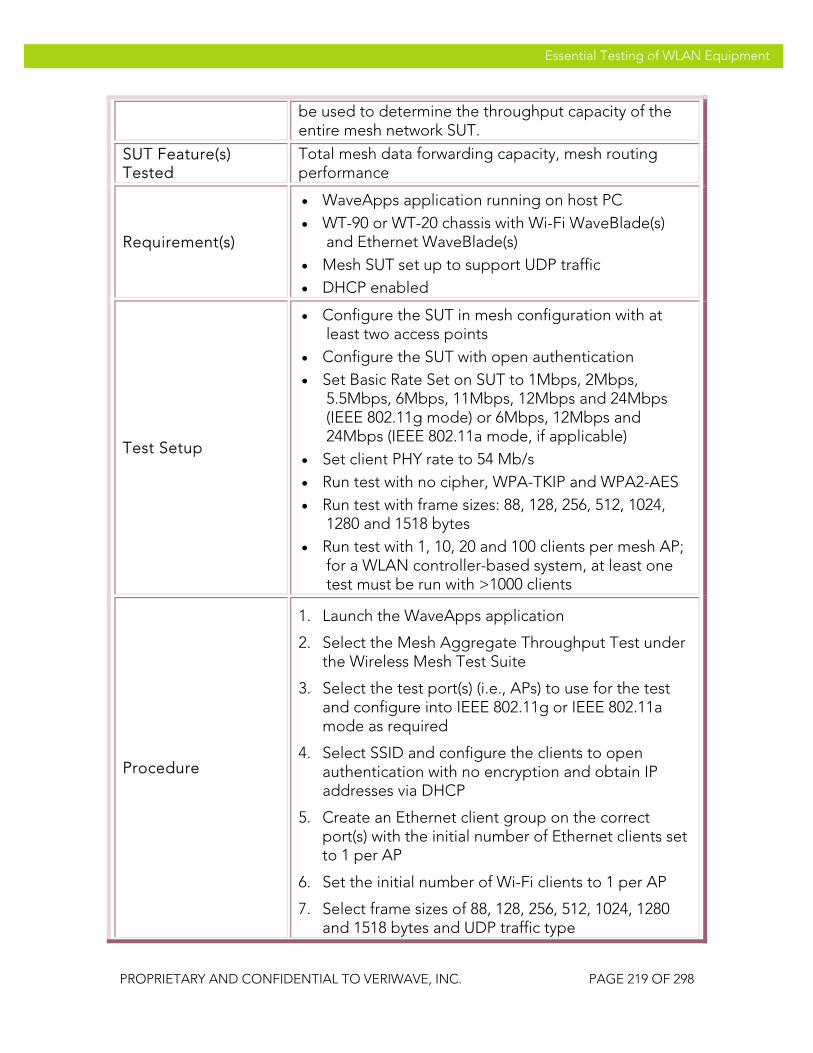
VeriWave, Inc. Essential Testing of WLAN Equipment
PROPRIETARY AND CONFIDENTIAL TO VERIWAVE, INC. PAGE 219 OF 298
Essential Testing of WLAN Equipment
be used to determine the throughput capacity of the entire mesh network SUT.
SUT Feature(s) Tested
Total mesh data forwarding capacity, mesh routing performance
Requirement(s)
• WaveApps application running on host PC • WT-90 or WT-20 chassis with Wi-Fi WaveBlade(s)
and Ethernet WaveBlade(s) • Mesh SUT set up to support UDP traffic • DHCP enabled
Test Setup
• Configure the SUT in mesh configuration with at least two access points
• Configure the SUT with open authentication • Set Basic Rate Set on SUT to 1Mbps, 2Mbps,
5.5Mbps, 6Mbps, 11Mbps, 12Mbps and 24Mbps (IEEE 802.11g mode) or 6Mbps, 12Mbps and 24Mbps (IEEE 802.11a mode, if applicable)
• Set client PHY rate to 54 Mb/s • Run test with no cipher, WPA-TKIP and WPA2-AES • Run test with frame sizes: 88, 128, 256, 512, 1024,
1280 and 1518 bytes • Run test with 1, 10, 20 and 100 clients per mesh AP;
for a WLAN controller-based system, at least one test must be run with >1000 clients
Procedure
1. Launch the WaveApps application
2. Select the Mesh Aggregate Throughput Test under the Wireless Mesh Test Suite
3. Select the test port(s) (i.e., APs) to use for the test and configure into IEEE 802.11g or IEEE 802.11a mode as required
4. Select SSID and configure the clients to open authentication with no encryption and obtain IP addresses via DHCP
5. Create an Ethernet client group on the correct port(s) with the initial number of Ethernet clients set to 1 per AP
6. Set the initial number of Wi-Fi clients to 1 per AP
7. Select frame sizes of 88, 128, 256, 512, 1024, 1280 and 1518 bytes and UDP traffic type

VeriWave, Inc. Essential Testing of WLAN Equipment
PROPRIETARY AND CONFIDENTIAL TO VERIWAVE, INC. PAGE 220 OF 298
Essential Testing of WLAN Equipment
8. Select Mesh Gateway to Mesh Hops (downstream) mapping
9. Run the test
10. Wait until test completes
11. Collect report and results data
12. Repeat steps 5 to 11 with 10, 20, and 100 clients per mesh AP configured on both Ethernet and Wi-Fi sides (one-to-one)
13. Repeat steps 5 to 12 with WPA-TKIP and WPA2-AES encryption modes
Test Priority Mandatory for Mesh SUTs
Test Type Performance
Pass/Fail Criteria
A Carrier Grade mesh SUT should achieve a downstream UDP throughput that is at least 75% of the theoretical maximum for all of the uplink channels put together: >= 22.5 Mbps for 1518 byte frames >= 18.8 Mbps for 1024 byte frames >= 12 Mbps for 512 byte frames >= 7.4 Mbps for 256 byte frames >= 4.1 Mbps for 128 byte frames >= 2.9 Mbps for 88 byte frames If the number of subscriber access channels is less than the number of uplink channels, then use that number instead.
PBTC-SP 108 Bidirectional_UDP_Aggregate_Throughput
Title Measure bidirectional UDP mesh throughput on an aggregate basis
Purpose
Measure the bidirectional UDP aggregate mesh throughput that can be achieved by the SUT; this can be used to determine the throughput capacity of the entire mesh network SUT.
SUT Feature(s) Tested
Total mesh data forwarding capacity, mesh routing performance
Requirement(s) • WaveApps application running on host PC • WT-90 or WT-20 chassis with Wi-Fi WaveBlade(s)

VeriWave, Inc. Essential Testing of WLAN Equipment
PROPRIETARY AND CONFIDENTIAL TO VERIWAVE, INC. PAGE 221 OF 298
Essential Testing of WLAN Equipment
and Ethernet WaveBlade(s) • Mesh SUT set up to support UDP traffic • DHCP enabled
Test Setup
• Configure the SUT in mesh configuration with at least two access points
• Configure the SUT with open authentication • Set Basic Rate Set on SUT to 1Mbps, 2Mbps,
5.5Mbps, 6Mbps, 11Mbps, 12Mbps and 24Mbps (IEEE 802.11g mode) or 6Mbps, 12Mbps and 24Mbps (IEEE 802.11a mode, if applicable)
• Set client PHY rate to 54 Mb/s • Run test with no cipher, WPA-TKIP and WPA2-AES • Run test with frame sizes: 88, 128, 256, 512, 1024,
1280 and 1518 bytes • Run test with 1, 10, 20 and 100 clients per mesh AP;
for a WLAN controller-based system, at least one test must be run with >1000 clients
Procedure
1. Launch the WaveApps application
2. Select the Mesh Aggregate Throughput Test under the Wireless Mesh Test Suite
3. Select the test port(s) (i.e., APs) to use for the test and configure into IEEE 802.11g or IEEE 802.11a mode as required
4. Select SSID and configure the clients to open authentication with no encryption and obtain IP addresses via DHCP
5. Create an Ethernet client group on the correct port(s) with the initial number of Ethernet clients set to 1 per AP
6. Set the initial number of Wi-Fi clients to 1 per AP
7. Select frame sizes of 88, 128, 256, 512, 1024, 1280 and 1518 bytes and UDP traffic type
8. Select Mesh Hops to Mesh Gateway traffic mapping with bidirectional mode
9. Run the test
10. Wait until test completes
11. Collect report and results data
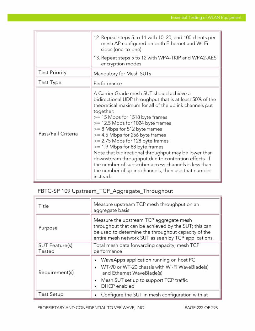
VeriWave, Inc. Essential Testing of WLAN Equipment
PROPRIETARY AND CONFIDENTIAL TO VERIWAVE, INC. PAGE 222 OF 298
Essential Testing of WLAN Equipment
12. Repeat steps 5 to 11 with 10, 20, and 100 clients per mesh AP configured on both Ethernet and Wi-Fi sides (one-to-one)
13. Repeat steps 5 to 12 with WPA-TKIP and WPA2-AES encryption modes
Test Priority Mandatory for Mesh SUTs
Test Type Performance
Pass/Fail Criteria
A Carrier Grade mesh SUT should achieve a bidirectional UDP throughput that is at least 50% of the theoretical maximum for all of the uplink channels put together: >= 15 Mbps for 1518 byte frames >= 12.5 Mbps for 1024 byte frames >= 8 Mbps for 512 byte frames >= 4.5 Mbps for 256 byte frames >= 2.75 Mbps for 128 byte frames >= 1.9 Mbps for 88 byte frames Note that bidirectional throughput may be lower than downstream throughput due to contention effects. If the number of subscriber access channels is less than the number of uplink channels, then use that number instead.
PBTC-SP 109 Upstream_TCP_Aggregate_Throughput
Title Measure upstream TCP mesh throughput on an aggregate basis
Purpose
Measure the upstream TCP aggregate mesh throughput that can be achieved by the SUT; this can be used to determine the throughput capacity of the entire mesh network SUT as seen by TCP applications.
SUT Feature(s) Tested
Total mesh data forwarding capacity, mesh TCP performance
Requirement(s)
• WaveApps application running on host PC • WT-90 or WT-20 chassis with Wi-Fi WaveBlade(s)
and Ethernet WaveBlade(s) • Mesh SUT set up to support TCP traffic • DHCP enabled
Test Setup • Configure the SUT in mesh configuration with at

VeriWave, Inc. Essential Testing of WLAN Equipment
PROPRIETARY AND CONFIDENTIAL TO VERIWAVE, INC. PAGE 223 OF 298
Essential Testing of WLAN Equipment
least two access points • Configure the SUT with open authentication • Set Basic Rate Set on SUT to 1Mbps, 2Mbps,
5.5Mbps, 6Mbps, 11Mbps, 12Mbps and 24Mbps (IEEE 802.11g mode) or 6Mbps, 12Mbps and 24Mbps (IEEE 802.11a mode, if applicable)
• Set client PHY rate to 54 Mb/s • Run test with no cipher, WPA-TKIP and WPA2-AES • Run test with frame sizes: 88, 128, 256, 512, 1024,
1280 and 1518 bytes • Run test with 1, 10, 20 and 100 clients per mesh AP;
for a WLAN controller-based system, at least one test must be run with >1000 clients
Procedure
1. Launch the WaveApps application
2. Select the Mesh Aggregate Throughput Test under the Wireless Mesh Test Suite
3. Select the test port(s) (i.e., APs) to use for the test and configure into IEEE 802.11g or IEEE 802.11a mode as required
4. Select SSID and configure the clients to open authentication with no encryption and obtain IP addresses via DHCP
5. Create an Ethernet client group on the correct port(s) with the initial number of Ethernet clients set to 1 per AP
6. Set the initial number of Wi-Fi clients to 1 per AP
7. Select frame sizes of 88, 128, 256, 512, 1024, 1280 and 1518 bytes and TCP traffic type
8. Select Mesh Hops to Mesh Gateway (upstream) mapping
9. Run the test
10. Wait until test completes
11. Collect report and results data
12. Repeat steps 5 to 11 with 10, 20, and 100 clients per mesh AP configured on both Ethernet and Wi-Fi sides (one-to-one)
13. Repeat steps 5 to 12 with WPA-TKIP and WPA2-AES encryption modes

VeriWave, Inc. Essential Testing of WLAN Equipment
PROPRIETARY AND CONFIDENTIAL TO VERIWAVE, INC. PAGE 224 OF 298
Essential Testing of WLAN Equipment
Test Priority Mandatory for Mesh SUTs
Test Type Performance
Pass/Fail Criteria
A Carrier Grade mesh SUT should achieve a upstream TCP throughput that is at least 50% of the theoretical maximum for all of the uplink channels put together: >= 15 Mbps for 1518 byte frames >= 12.5 Mbps for 1024 byte frames >= 8 Mbps for 512 byte frames >= 4.5 Mbps for 256 byte frames >= 2.75 Mbps for 128 byte frames >= 1.9 Mbps for 88 byte frames If the number of subscriber access channels is less than the number of uplink channels, then use that number instead.
PBTC-SP 110 Downstream_TCP_Aggregate_Throughput
Title Measure downstream TCP mesh throughput on an aggregate basis
Purpose
Measure the downstream TCP aggregate mesh throughput that can be achieved by the SUT; this can be used to determine the throughput capacity of the entire mesh network SUT as seen by TCP applications.
SUT Feature(s) Tested
Total mesh data forwarding capacity, mesh TCP performance
Requirement(s)
• WaveApps application running on host PC • WT-90 or WT-20 chassis with Wi-Fi WaveBlade(s)
and Ethernet WaveBlade(s) • Mesh SUT set up to support TCP traffic • DHCP enabled
Test Setup
• Configure the SUT in mesh configuration with at least two access points
• Configure the SUT with open authentication • Set Basic Rate Set on SUT to 1Mbps, 2Mbps,
5.5Mbps, 6Mbps, 11Mbps, 12Mbps and 24Mbps (IEEE 802.11g mode) or 6Mbps, 12Mbps and 24Mbps (IEEE 802.11a mode, if applicable)
• Set client PHY rate to 54 Mb/s • Run test with no cipher, WPA-TKIP and WPA2-AES

VeriWave, Inc. Essential Testing of WLAN Equipment
PROPRIETARY AND CONFIDENTIAL TO VERIWAVE, INC. PAGE 225 OF 298
Essential Testing of WLAN Equipment
• Run test with frame sizes: 88, 128, 256, 512, 1024, 1280 and 1518 bytes
• Run test with 1, 10, 20 and 100 clients per mesh AP; for a WLAN controller-based system, at least one test must be run with >1000 clients
Procedure
1. Launch the WaveApps application
2. Select the Mesh Aggregate Throughput Test under the Wireless Mesh Test Suite
3. Select the test port(s) (i.e., APs) to use for the test and configure into IEEE 802.11g or IEEE 802.11a mode as required
4. Select SSID and configure the clients to open authentication with no encryption and obtain IP addresses via DHCP
5. Create an Ethernet client group on the correct port(s) with the initial number of Ethernet clients set to 1 per AP
6. Set the initial number of Wi-Fi clients to 1 per AP
7. Select frame sizes of 88, 128, 256, 512, 1024, 1280 and 1518 bytes and TCP traffic type
8. Select Mesh Gateway to Mesh Hops (downstream) mapping
9. Run the test
10. Wait until test completes
11. Collect report and results data
12. Repeat steps 5 to 11 with 10, 20, and 100 clients per mesh AP configured on both Ethernet and Wi-Fi sides (one-to-one)
13. Repeat steps 5 to 12 with WPA-TKIP and WPA2-AES encryption modes
Test Priority Mandatory for Mesh SUTs
Test Type Performance

VeriWave, Inc. Essential Testing of WLAN Equipment
PROPRIETARY AND CONFIDENTIAL TO VERIWAVE, INC. PAGE 226 OF 298
Essential Testing of WLAN Equipment
Pass/Fail Criteria
A Carrier Grade mesh SUT should achieve a downstream TCP throughput that is at least 75% of the theoretical maximum for all of the uplink channels put together: >= 22.5 Mbps for 1518 byte frames >= 18.8 Mbps for 1024 byte frames >= 12 Mbps for 512 byte frames >= 7.4 Mbps for 256 byte frames >= 4.1 Mbps for 128 byte frames >= 2.9 Mbps for 88 byte frames If the number of subscriber access channels is less than the number of uplink channels, then use that number instead.
PBTC-SP 111 Bidirectional_TCP_Aggregate_Throughput
Title Measure bidirectional TCP mesh throughput on an aggregate basis
Purpose
Measure the bidirectional TCP aggregate mesh throughput that can be achieved by the SUT; this can be used to determine the throughput capacity of the entire mesh network SUT as seen by TCP applications.
SUT Feature(s) Tested
Total mesh data forwarding capacity, mesh TCP performance
Requirement(s)
• WaveApps application running on host PC • WT-90 or WT-20 chassis with Wi-Fi WaveBlade(s)
and Ethernet WaveBlade(s) • Mesh SUT set up to support TCP traffic • DHCP enabled
Test Setup
• Configure the SUT in mesh configuration with at least two access points
• Configure the SUT with open authentication • Set Basic Rate Set on SUT to 1Mbps, 2Mbps,
5.5Mbps, 6Mbps, 11Mbps, 12Mbps and 24Mbps (IEEE 802.11g mode) or 6Mbps, 12Mbps and 24Mbps (IEEE 802.11a mode, if applicable)
• Set client PHY rate to 54 Mb/s • Run test with no cipher, WPA-TKIP and WPA2-AES • Run test with frame sizes: 88, 128, 256, 512, 1024,
1280 and 1518 bytes

VeriWave, Inc. Essential Testing of WLAN Equipment
PROPRIETARY AND CONFIDENTIAL TO VERIWAVE, INC. PAGE 227 OF 298
Essential Testing of WLAN Equipment
• Run test with 1, 10, 20 and 100 clients per mesh AP; for a WLAN controller-based system, at least one test must be run with >1000 clients
Procedure
1. Launch the WaveApps application
2. Select the Mesh Aggregate Throughput Test under the Wireless Mesh Test Suite
3. Select the test port(s) (i.e., APs) to use for the test and configure into IEEE 802.11g or IEEE 802.11a mode as required
4. Select SSID and configure the clients to open authentication with no encryption and obtain IP addresses via DHCP
5. Create an Ethernet client group on the correct port(s) with the initial number of Ethernet clients set to 1 per AP
6. Set the initial number of Wi-Fi clients to 1 per AP
7. Select frame sizes of 88, 128, 256, 512, 1024, 1280 and 1518 bytes and TCP traffic type
8. Select Mesh Hops to Mesh Gateway traffic mapping with bidirectional mode
9. Run the test
10. Wait until test completes
11. Collect report and results data
12. Repeat steps 5 to 11 with 10, 20, and 100 clients per mesh AP configured on both Ethernet and Wi-Fi sides (one-to-one)
13. Repeat steps 5 to 12 with WPA-TKIP and WPA2-AES encryption modes
Test Priority Mandatory for Mesh SUTs
Test Type Performance
Pass/Fail Criteria
A Carrier Grade mesh SUT should achieve a bidirectional TCP throughput that is at least 50% of the theoretical maximum for all of the uplink channels put together: >= 15 Mbps * number of channels for 1518 byte frames >= 12.5 Mbps for 1024 byte frames

VeriWave, Inc. Essential Testing of WLAN Equipment
PROPRIETARY AND CONFIDENTIAL TO VERIWAVE, INC. PAGE 228 OF 298
Essential Testing of WLAN Equipment
>= 8 Mbps for 512 byte frames >= 4.5 Mbps for 256 byte frames >= 2.75 Mbps for 128 byte frames >= 1.9 Mbps for 88 byte frames Note that bidirectional throughput may be lower than downstream throughput due to contention effects. If the number of subscriber access channels is less than the number of uplink channels, then use that number instead.
Mesh Per-Hop and Aggregate Packet Latency
The following mesh latency tests measure the delay required for packets to be forwarded through the SUT, both on a per-hop basis (i.e., individually for each mesh AP) and an aggregate basis (i.e., collectively for all mesh APs taken as a whole), under increasing client load. Delay-sensitive services such as streaming video and VoIP require low latency for a high-quality user experience. The latency tests present the SUT with an intended load for each frame size and measures the time it takes for each packet to travel from the source port to the destination port through the SUT.
Also see the section dealing with tests on interference effects. Note that interference effects are not applied to the tests in this section.
The intended load is divided equally between SUT ports, and should be adjusted to be just below the SUT throughput (i.e., the value measured using a previous throughput test). The latency tests are conducted with a variety of frame sizes, numbers of clients, security modes, and directions (i.e., upstream and downstream). Only UDP traffic is used for these latency tests.
Note that the test cases must be performed in the appropriate band used for client and subscriber access to the SUT. In many cases, this is the IEEE 802.11b/g channel set (2.4 GHz).
PBTC-SP 140 Upstream_UDP_Per-Hop_Latency
Title Measure upstream UDP mesh latency per-hop
Purpose Measure the upstream UDP per-hop mesh latency that can be achieved through the SUT; this gives the latency seen by individual subscribers.
SUT Feature(s) Tested
Mesh per-hop buffering and forwarding efficiency and delays, mesh routing efficacy
Requirement(s) • WaveApps application running on host PC • WT-90 or WT-20 chassis with Wi-Fi WaveBlade(s)
and Ethernet WaveBlade(s)

VeriWave, Inc. Essential Testing of WLAN Equipment
PROPRIETARY AND CONFIDENTIAL TO VERIWAVE, INC. PAGE 229 OF 298
Essential Testing of WLAN Equipment
• Mesh SUT set up to support UDP traffic • DHCP enabled
Test Setup
• Configure the SUT in mesh configuration with at least two access points
• Configure the SUT with open authentication • Set Basic Rate Set on SUT to 1Mbps, 2Mbps,
5.5Mbps, 6Mbps, 11Mbps, 12Mbps and 24Mbps (IEEE 802.11g mode) or 6Mbps, 12Mbps and 24Mbps (IEEE 802.11a mode, if applicable)
• Set client PHY rate to 54 Mb/s • Set intended load (ILOAD) for each frame size to
90% of the throughput of the SUT as obtained from the mesh per-hop throughput tests (if the SUT throughput is unknown, use theoretical values)
• Run test with no cipher, WPA-TKIP and WPA2-AES • Run test with frame sizes: 88, 128, 256, 512, 1024,
1280 and 1518 bytes • Run test with 1, 10, 20 and 100 clients per mesh AP;
for a WLAN controller-based system, at least one test must be run with >1000 clients
Procedure
1. Launch the WaveApps application
2. Select the Mesh Per-Hop Latency Test under the Wireless Mesh Test Suite
3. Select the test port(s) (i.e., APs) to use for the test and configure into IEEE 802.11g or IEEE 802.11a mode as required
4. Select SSID and configure the clients to open authentication with no encryption and obtain IP addresses via DHCP
5. Create an Ethernet client group on the correct port(s) with the initial number of Ethernet clients set to 1 per AP
6. Set the initial number of Wi-Fi clients to 1 per AP
7. Select frame sizes of 88, 128, 256, 512, 1024, 1280 and 1518 bytes and UDP traffic type; adjust the intended load (ILOAD) table to target traffic load as per test setup details above
8. Select Mesh Hops to Mesh Gateway (upstream) mapping

VeriWave, Inc. Essential Testing of WLAN Equipment
PROPRIETARY AND CONFIDENTIAL TO VERIWAVE, INC. PAGE 230 OF 298
Essential Testing of WLAN Equipment
9. Run the test
10. Wait until test completes
11. Collect report and results data
12. Repeat steps 5 to 11 with 10, 20, and 100 clients per mesh AP configured on both Ethernet and Wi-Fi sides (one-to-one)
13. Repeat steps 5 to 12 with WPA-TKIP and WPA2-AES encryption modes
Test Priority Mandatory for Mesh SUTs
Test Type Performance
Pass/Fail Criteria
A Carrier Grade SUT should not impose a packet latency of more than 50 milliseconds from any hop to the portal under the specified loading, in order to support delay-sensitive voice and multimedia traffic.
PBTC-SP 141 Downstream_UDP_Per-Hop_Latency
Title Measure downstream UDP mesh latency per-hop
Purpose Measure the downstream UDP per-hop mesh latency that can be achieved through the SUT; this gives the latency seen by individual subscribers.
SUT Feature(s) Tested
Mesh per-hop buffering and forwarding efficiency and delays, mesh routing efficacy
Requirement(s)
• WaveApps application running on host PC • WT-90 or WT-20 chassis with Wi-Fi WaveBlade(s)
and Ethernet WaveBlade(s) • Mesh SUT set up to support UDP traffic • DHCP enabled
Test Setup
• Configure the SUT in mesh configuration with at least two access points
• Configure the SUT with open authentication • Set Basic Rate Set on SUT to 1Mbps, 2Mbps,
5.5Mbps, 6Mbps, 11Mbps, 12Mbps and 24Mbps (IEEE 802.11g mode) or 6Mbps, 12Mbps and 24Mbps (IEEE 802.11a mode, if applicable)
• Set client PHY rate to 54 Mb/s • Set intended load (ILOAD) for each frame size to

VeriWave, Inc. Essential Testing of WLAN Equipment
PROPRIETARY AND CONFIDENTIAL TO VERIWAVE, INC. PAGE 231 OF 298
Essential Testing of WLAN Equipment
90% of the throughput of the SUT as obtained from the mesh per-hop throughput tests (if the SUT throughput is unknown, use theoretical values)
• Run test with no cipher, WPA-TKIP and WPA2-AES • Run test with frame sizes: 88, 128, 256, 512, 1024,
1280 and 1518 bytes • Run test with 1, 10, 20 and 100 clients per mesh AP;
for a WLAN controller-based system, at least one test must be run with >1000 clients
Procedure
1. Launch the WaveApps application
2. Select the Mesh Per-Hop Latency Test under the Wireless Mesh Test Suite
3. Select the test port(s) (i.e., APs) to use for the test and configure into IEEE 802.11g or IEEE 802.11a mode as required
4. Select SSID and configure the clients to open authentication with no encryption and obtain IP addresses via DHCP
5. Create an Ethernet client group on the correct port(s) with the initial number of Ethernet clients set to 1 per AP
6. Set the initial number of Wi-Fi clients to 1 per AP
7. Select frame sizes of 88, 128, 256, 512, 1024, 1280 and 1518 bytes and UDP traffic type; adjust the intended load (ILOAD) table to target traffic load as per test setup details above
8. Select Mesh Gateway to Mesh Hops (downstream) mapping
9. Run the test
10. Wait until test completes
11. Collect report and results data
12. Repeat steps 5 to 11 with 10, 20, and 100 clients per mesh AP configured on both Ethernet and Wi-Fi sides (one-to-one)
13. Repeat steps 5 to 12 with WPA-TKIP and WPA2-AES encryption modes
Test Priority Mandatory for Mesh SUTs
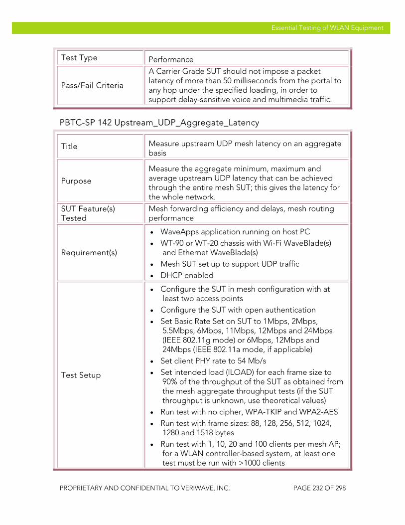
VeriWave, Inc. Essential Testing of WLAN Equipment
PROPRIETARY AND CONFIDENTIAL TO VERIWAVE, INC. PAGE 232 OF 298
Essential Testing of WLAN Equipment
Test Type Performance
Pass/Fail Criteria
A Carrier Grade SUT should not impose a packet latency of more than 50 milliseconds from the portal to any hop under the specified loading, in order to support delay-sensitive voice and multimedia traffic.
PBTC-SP 142 Upstream_UDP_Aggregate_Latency
Title Measure upstream UDP mesh latency on an aggregate basis
Purpose
Measure the aggregate minimum, maximum and average upstream UDP latency that can be achieved through the entire mesh SUT; this gives the latency for the whole network.
SUT Feature(s) Tested
Mesh forwarding efficiency and delays, mesh routing performance
Requirement(s)
• WaveApps application running on host PC • WT-90 or WT-20 chassis with Wi-Fi WaveBlade(s)
and Ethernet WaveBlade(s) • Mesh SUT set up to support UDP traffic • DHCP enabled
Test Setup
• Configure the SUT in mesh configuration with at least two access points
• Configure the SUT with open authentication • Set Basic Rate Set on SUT to 1Mbps, 2Mbps,
5.5Mbps, 6Mbps, 11Mbps, 12Mbps and 24Mbps (IEEE 802.11g mode) or 6Mbps, 12Mbps and 24Mbps (IEEE 802.11a mode, if applicable)
• Set client PHY rate to 54 Mb/s • Set intended load (ILOAD) for each frame size to
90% of the throughput of the SUT as obtained from the mesh aggregate throughput tests (if the SUT throughput is unknown, use theoretical values)
• Run test with no cipher, WPA-TKIP and WPA2-AES • Run test with frame sizes: 88, 128, 256, 512, 1024,
1280 and 1518 bytes • Run test with 1, 10, 20 and 100 clients per mesh AP;
for a WLAN controller-based system, at least one test must be run with >1000 clients

VeriWave, Inc. Essential Testing of WLAN Equipment
PROPRIETARY AND CONFIDENTIAL TO VERIWAVE, INC. PAGE 233 OF 298
Essential Testing of WLAN Equipment
Procedure
1. Launch the WaveApps application
2. Select the Mesh Aggregate Latency Test under the Wireless Mesh Test Suite
3. Select the test port(s) (i.e., APs) to use for the test and configure into IEEE 802.11g or IEEE 802.11a mode as required
4. Select SSID and configure the clients to open authentication with no encryption and obtain IP addresses via DHCP
5. Create an Ethernet client group on the correct port(s) with the initial number of Ethernet clients set to 1 per AP
6. Set the initial number of Wi-Fi clients to 1 per AP
7. Select frame sizes of 88, 128, 256, 512, 1024, 1280 and 1518 bytes and UDP traffic type; adjust the intended load (ILOAD) table to target traffic load as per test setup details above
8. Select Mesh Hops to Mesh Gateway (upstream) mapping
9. Run the test
10. Wait until test completes
11. Collect report and results data
12. Repeat steps 5 to 11 with 10, 20, and 100 clients per mesh AP configured on both Ethernet and Wi-Fi sides (one-to-one)
13. Repeat steps 5 to 12 with WPA-TKIP and WPA2-AES encryption modes
Test Priority Mandatory for Mesh SUTs
Test Type Performance
Pass/Fail Criteria
A Carrier Grade SUT should not impose a maximum packet latency of more than 50 milliseconds under the specified loading, in order to support delay-sensitive voice and multimedia traffic.
PBTC-SP 143 Downstream_UDP_Aggregate_Latency
Title Measure downstream UDP mesh latency on an

VeriWave, Inc. Essential Testing of WLAN Equipment
PROPRIETARY AND CONFIDENTIAL TO VERIWAVE, INC. PAGE 234 OF 298
Essential Testing of WLAN Equipment
aggregate basis
Purpose
Measure the aggregate minimum, maximum and average downstream UDP latency that can be achieved through the entire mesh SUT; this gives the latency for the whole network.
SUT Feature(s) Tested
Mesh forwarding efficiency and delays, mesh routing performance
Requirement(s)
• WaveApps application running on host PC • WT-90 or WT-20 chassis with Wi-Fi WaveBlade(s)
and Ethernet WaveBlade(s) • Mesh SUT set up to support UDP traffic • DHCP enabled
Test Setup
• Configure the SUT in mesh configuration with at least two access points
• Configure the SUT with open authentication • Set Basic Rate Set on SUT to 1Mbps, 2Mbps,
5.5Mbps, 6Mbps, 11Mbps, 12Mbps and 24Mbps (IEEE 802.11g mode) or 6Mbps, 12Mbps and 24Mbps (IEEE 802.11a mode, if applicable)
• Set client PHY rate to 54 Mb/s • Set intended load (ILOAD) for each frame size to
90% of the throughput of the SUT as obtained from the mesh aggregate throughput tests (if the SUT throughput is unknown, use theoretical values)
• Run test with no cipher, WPA-TKIP and WPA2-AES • Run test with frame sizes: 88, 128, 256, 512, 1024,
1280 and 1518 bytes • Run test with 1, 10, 20 and 100 clients per mesh AP;
for a WLAN controller-based system, at least one test must be run with >1000 clients
Procedure
1. Launch the WaveApps application
2. Select the Mesh Aggregate Latency Test under the Wireless Mesh Test Suite
3. Select the test port(s) (i.e., APs) to use for the test and configure into IEEE 802.11g or IEEE 802.11a mode as required
4. Select SSID and configure the clients to open authentication with no encryption and obtain IP
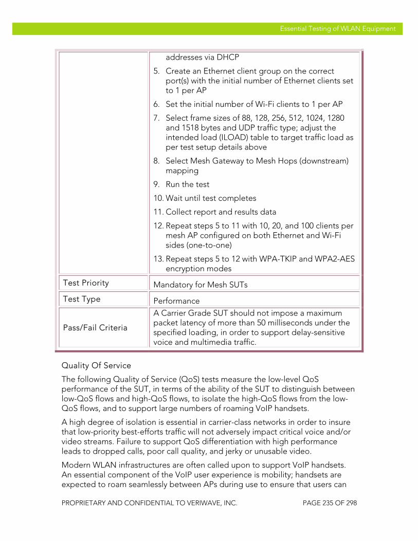
VeriWave, Inc. Essential Testing of WLAN Equipment
PROPRIETARY AND CONFIDENTIAL TO VERIWAVE, INC. PAGE 235 OF 298
Essential Testing of WLAN Equipment
addresses via DHCP
5. Create an Ethernet client group on the correct port(s) with the initial number of Ethernet clients set to 1 per AP
6. Set the initial number of Wi-Fi clients to 1 per AP
7. Select frame sizes of 88, 128, 256, 512, 1024, 1280 and 1518 bytes and UDP traffic type; adjust the intended load (ILOAD) table to target traffic load as per test setup details above
8. Select Mesh Gateway to Mesh Hops (downstream) mapping
9. Run the test
10. Wait until test completes
11. Collect report and results data
12. Repeat steps 5 to 11 with 10, 20, and 100 clients per mesh AP configured on both Ethernet and Wi-Fi sides (one-to-one)
13. Repeat steps 5 to 12 with WPA-TKIP and WPA2-AES encryption modes
Test Priority Mandatory for Mesh SUTs
Test Type Performance
Pass/Fail Criteria
A Carrier Grade SUT should not impose a maximum packet latency of more than 50 milliseconds under the specified loading, in order to support delay-sensitive voice and multimedia traffic.
Quality Of Service
The following Quality of Service (QoS) tests measure the low-level QoS performance of the SUT, in terms of the ability of the SUT to distinguish between low-QoS flows and high-QoS flows, to isolate the high-QoS flows from the low-QoS flows, and to support large numbers of roaming VoIP handsets.
A high degree of isolation is essential in carrier-class networks in order to insure that low-priority best-efforts traffic will not adversely impact critical voice and/or video streams. Failure to support QoS differentiation with high performance leads to dropped calls, poor call quality, and jerky or unusable video.
Modern WLAN infrastructures are often called upon to support VoIP handsets. An essential component of the VoIP user experience is mobility; handsets are expected to roam seamlessly between APs during use to ensure that users can
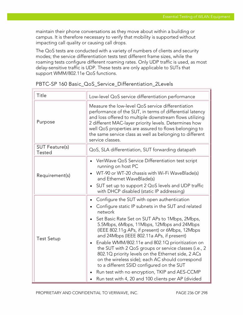
VeriWave, Inc. Essential Testing of WLAN Equipment
PROPRIETARY AND CONFIDENTIAL TO VERIWAVE, INC. PAGE 236 OF 298
Essential Testing of WLAN Equipment
maintain their phone conversations as they move about within a building or campus. It is therefore necessary to verify that mobility is supported without impacting call quality or causing call drops.
The QoS tests are conducted with a variety of numbers of clients and security modes; the service differentiation tests test different frame sizes, while the roaming tests configure different roaming rates. Only UDP traffic is used, as most delay-sensitive traffic is UDP. These tests are only applicable to SUTs that support WMM/802.11e QoS functions.
PBTC-SP 160 Basic_QoS_Service_Differentiation_2Levels
Title Low-level QoS service differentiation performance
Purpose
Measure the low-level QoS service differentiation performance of the SUT, in terms of differential latency and loss offered to multiple downstream flows utilizing 2 different MAC-layer priority levels. Determines how well QoS properties are assured to flows belonging to the same service class as well as belonging to different service classes.
SUT Feature(s) Tested
QoS, SLA differentiation, SUT forwarding datapath
Requirement(s)
• VeriWave QoS Service Differentiation test script running on host PC
• WT-90 or WT-20 chassis with Wi-Fi WaveBlade(s) and Ethernet WaveBlade(s)
• SUT set up to support 2 QoS levels and UDP traffic with DHCP disabled (static IP addressing)
Test Setup
• Configure the SUT with open authentication • Configure static IP subnets in the SUT and related
network • Set Basic Rate Set on SUT APs to 1Mbps, 2Mbps,
5.5Mbps, 6Mbps, 11Mbps, 12Mbps and 24Mbps (IEEE 802.11g APs, if present) or 6Mbps, 12Mbps and 24Mbps (IEEE 802.11a APs, if present)
• Enable WMM/802.11e and 802.1Q prioritization on the SUT with 2 QoS groups or service classes (i.e., 2 802.1Q priority levels on the Ethernet side, 2 ACs on the wireless side); each AC should correspond to a different SSID configured on the SUT
• Run test with no encryption, TKIP and AES-CCMP • Run test with 4, 20 and 100 clients per AP (divided

VeriWave, Inc. Essential Testing of WLAN Equipment
PROPRIETARY AND CONFIDENTIAL TO VERIWAVE, INC. PAGE 237 OF 298
Essential Testing of WLAN Equipment
among 2 groups) • Run test with UDP frame sizes: 88, 128, 256, 512,
1024, 1280 and 1518 bytes • Run test with intended SUT traffic loads of 10, 20
and 40 Mb/s per AP
Procedure
1. Configure the QoS Service Differentiation script according to the trial being run, as per steps 2 through 11
2. Configure the test port(s) (i.e., APs in SUT) and channel(s) to use for the test
3. Configure the flow PHY rate to 54 Mb/s
4. Configure the trial duration (data transmit time) to 120 seconds
5. Configure a single Ethernet client with a suitable static IP address
6. Configure the Ethernet client as the traffic source and set the traffic type to RTP
7. Configure 2 WLAN client groups with static IP addresses and user priorities as follows:
a. Client Group 1: UserPriority=0 (Best Effort)
b. Client Group 2: UserPriority=6 (Voice)
8. Configure the initial WLAN security mode to open (no encryption)
9. Configure the initial number of clients per group to 2 per AP (i.e., 4 x N total clients, where N is the number of APs)
10. Configure the initial aggregate SUT traffic load to (10 x N) Mb/s, where N is the number of APs
11. Configure the initial packet size to 88 bytes
12. Run the test by executing the script
13. Wait until the test completes and the results have been written
14. Save the per-client (i.e., per-flow) statistics for latency, packet loss and forwarding rate
15. Repeat steps 12 through 14 with frame sizes of 128, 256, 512, 1024, 1280 and 1518 bytes

VeriWave, Inc. Essential Testing of WLAN Equipment
PROPRIETARY AND CONFIDENTIAL TO VERIWAVE, INC. PAGE 238 OF 298
Essential Testing of WLAN Equipment
16. Repeat steps 11 through 15 with aggregate SUT offered loads of (20 x N) and (40 x N) Mb/s
17. Repeat steps 10 through 16 with 10 and 50 clients per group per AP (i.e., 20 x N and 100 x N total clients respectively)
18. Repeat steps 9 through 17 with WPA-PSK (i.e., TKIP) and WPA2-PSK (i.e., AES-CCMP) security modes configured for all the WLAN clients
Test Priority High
Test Type QoS
Pass/Fail Criteria
A Carrier Class SUT will ensure that clients having higher user priority will experience lower loss and jitter and support higher forwarding rates than clients with lower user priority. (The user priority ordering is: voice (highest), video, background, best efforts (lowest).) Further, clients within the same group (and thus having the same user priority level) should experience similar loss, jitter and forwarding rates, to within +/- 10% of the average for the group.
PBTC-SP 161 Basic_QoS_Service_Differentiation_4Levels
Title Low-level QoS service differentiation performance
Purpose
Measure the low-level QoS service differentiation performance of the SUT, in terms of differential latency and loss offered to multiple downstream flows utilizing 4 different MAC-layer priority levels. Determines how well QoS properties are assured to flows belonging to the same service class as well as belonging to different service classes.
SUT Feature(s) Tested
QoS, SLA differentiation, SUT forwarding datapath
Requirement(s)
• VeriWave QoS Service Differentiation test script running on host PC
• WT-90 or WT-20 chassis with Wi-Fi WaveBlade(s) and Ethernet WaveBlade(s)
• SUT set up to support 4 QoS levels and UDP traffic with DHCP disabled (static IP addressing)
Test Setup • Configure the SUT with open authentication
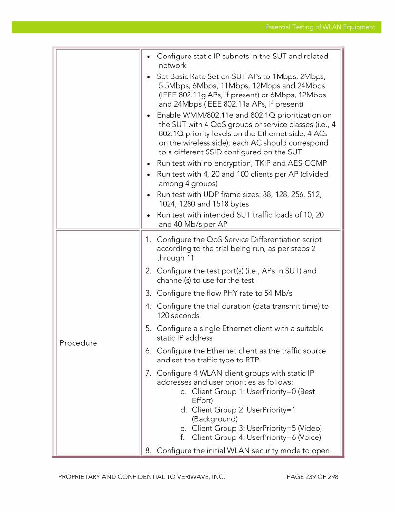
VeriWave, Inc. Essential Testing of WLAN Equipment
PROPRIETARY AND CONFIDENTIAL TO VERIWAVE, INC. PAGE 239 OF 298
Essential Testing of WLAN Equipment
• Configure static IP subnets in the SUT and related network
• Set Basic Rate Set on SUT APs to 1Mbps, 2Mbps, 5.5Mbps, 6Mbps, 11Mbps, 12Mbps and 24Mbps (IEEE 802.11g APs, if present) or 6Mbps, 12Mbps and 24Mbps (IEEE 802.11a APs, if present)
• Enable WMM/802.11e and 802.1Q prioritization on the SUT with 4 QoS groups or service classes (i.e., 4 802.1Q priority levels on the Ethernet side, 4 ACs on the wireless side); each AC should correspond to a different SSID configured on the SUT
• Run test with no encryption, TKIP and AES-CCMP • Run test with 4, 20 and 100 clients per AP (divided
among 4 groups) • Run test with UDP frame sizes: 88, 128, 256, 512,
1024, 1280 and 1518 bytes • Run test with intended SUT traffic loads of 10, 20
and 40 Mb/s per AP
Procedure
1. Configure the QoS Service Differentiation script according to the trial being run, as per steps 2 through 11
2. Configure the test port(s) (i.e., APs in SUT) and channel(s) to use for the test
3. Configure the flow PHY rate to 54 Mb/s
4. Configure the trial duration (data transmit time) to 120 seconds
5. Configure a single Ethernet client with a suitable static IP address
6. Configure the Ethernet client as the traffic source and set the traffic type to RTP
7. Configure 4 WLAN client groups with static IP addresses and user priorities as follows:
c. Client Group 1: UserPriority=0 (Best Effort)
d. Client Group 2: UserPriority=1 (Background)
e. Client Group 3: UserPriority=5 (Video) f. Client Group 4: UserPriority=6 (Voice)
8. Configure the initial WLAN security mode to open

VeriWave, Inc. Essential Testing of WLAN Equipment
PROPRIETARY AND CONFIDENTIAL TO VERIWAVE, INC. PAGE 240 OF 298
Essential Testing of WLAN Equipment
(no encryption)
9. Configure the initial number of clients per group to 1 per AP (i.e., 4 x N total clients, where N is the number of APs)
10. Configure the initial aggregate SUT traffic load to (10 x N) Mb/s, where N is the number of APs
11. Configure the initial packet size to 88 bytes
12. Run the test by executing the script
13. Wait until the test completes and the results have been written
14. Save the per-client (i.e., per-flow) statistics for latency, packet loss and forwarding rate
15. Repeat steps 12 through 14 with frame sizes of 128, 256, 512, 1024, 1280 and 1518 bytes
16. Repeat steps 11 through 15 with aggregate SUT offered loads of (20 x N) and (40 x N) Mb/s
17. Repeat steps 10 through 16 with 5 and 25 clients per group per AP (i.e., 20 x N and 100 x N total clients respectively)
18. Repeat steps 9 through 17 with WPA-PSK (i.e., TKIP) and WPA2-PSK (i.e., AES-CCMP) security modes configured for all the WLAN clients
Test Priority Medium
Test Type QoS
Pass/Fail Criteria
A Carrier Grade SUT will ensure that clients having higher user priority will experience lower loss and jitter and support higher forwarding rates than clients with lower user priority. (The user priority ordering is: voice (highest), video, background, best efforts (lowest).) Further, clients within the same group (and thus having the same user priority level) should experience similar loss, jitter and forwarding rates, to within +/- 10% of the average for the group.
PBTC-SP 162 VoIP_SLA_Assurance
Title Measure voice SLA assurance under high data load conditions
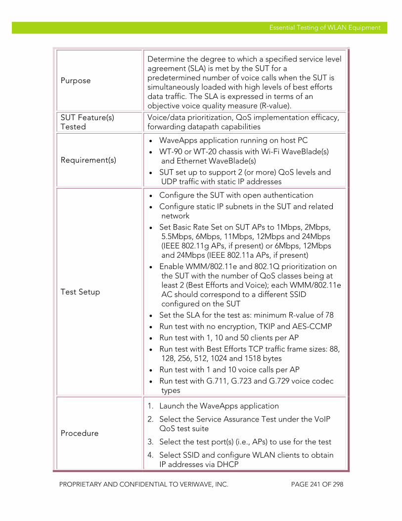
VeriWave, Inc. Essential Testing of WLAN Equipment
PROPRIETARY AND CONFIDENTIAL TO VERIWAVE, INC. PAGE 241 OF 298
Essential Testing of WLAN Equipment
Purpose
Determine the degree to which a specified service level agreement (SLA) is met by the SUT for a predetermined number of voice calls when the SUT is simultaneously loaded with high levels of best efforts data traffic. The SLA is expressed in terms of an objective voice quality measure (R-value).
SUT Feature(s) Tested
Voice/data prioritization, QoS implementation efficacy, forwarding datapath capabilities
Requirement(s)
• WaveApps application running on host PC • WT-90 or WT-20 chassis with Wi-Fi WaveBlade(s)
and Ethernet WaveBlade(s) • SUT set up to support 2 (or more) QoS levels and
UDP traffic with static IP addresses
Test Setup
• Configure the SUT with open authentication • Configure static IP subnets in the SUT and related
network • Set Basic Rate Set on SUT APs to 1Mbps, 2Mbps,
5.5Mbps, 6Mbps, 11Mbps, 12Mbps and 24Mbps (IEEE 802.11g APs, if present) or 6Mbps, 12Mbps and 24Mbps (IEEE 802.11a APs, if present)
• Enable WMM/802.11e and 802.1Q prioritization on the SUT with the number of QoS classes being at least 2 (Best Efforts and Voice); each WMM/802.11e AC should correspond to a different SSID configured on the SUT
• Set the SLA for the test as: minimum R-value of 78 • Run test with no encryption, TKIP and AES-CCMP • Run test with 1, 10 and 50 clients per AP • Run test with Best Efforts TCP traffic frame sizes: 88,
128, 256, 512, 1024 and 1518 bytes • Run test with 1 and 10 voice calls per AP • Run test with G.711, G.723 and G.729 voice codec
types
Procedure
1. Launch the WaveApps application
2. Select the Service Assurance Test under the VoIP QoS test suite
3. Select the test port(s) (i.e., APs) to use for the test
4. Select SSID and configure WLAN clients to obtain IP addresses via DHCP
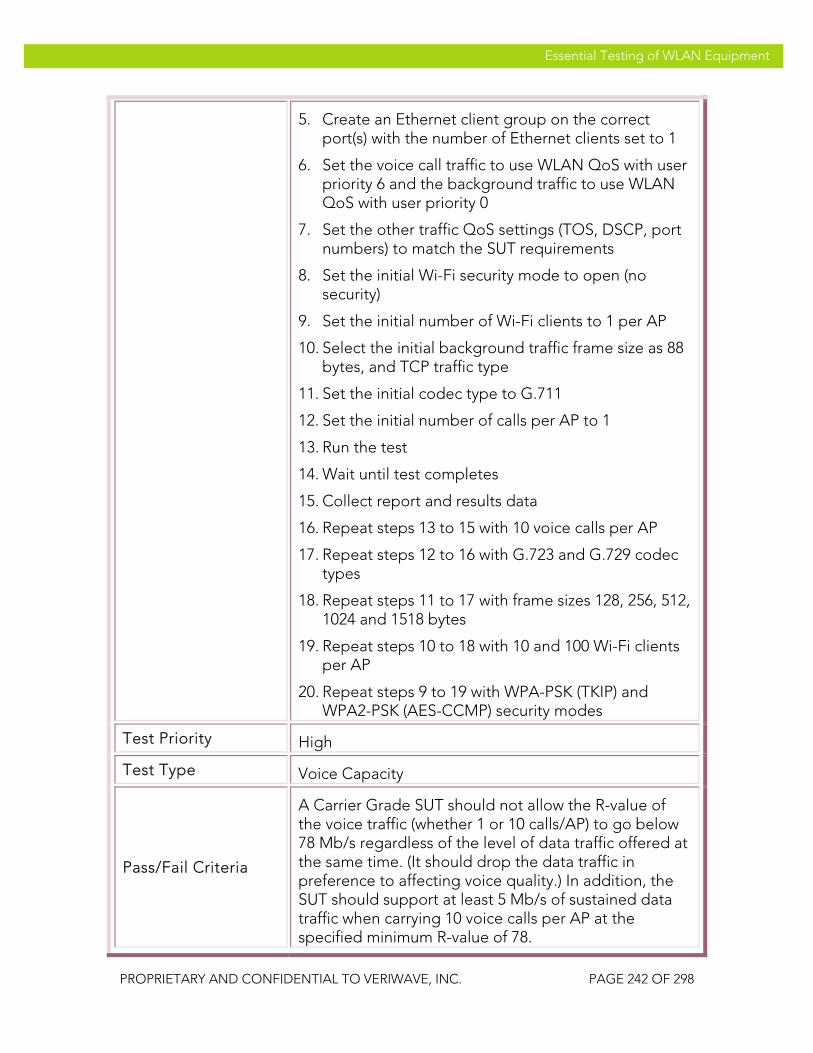
VeriWave, Inc. Essential Testing of WLAN Equipment
PROPRIETARY AND CONFIDENTIAL TO VERIWAVE, INC. PAGE 242 OF 298
Essential Testing of WLAN Equipment
5. Create an Ethernet client group on the correct port(s) with the number of Ethernet clients set to 1
6. Set the voice call traffic to use WLAN QoS with user priority 6 and the background traffic to use WLAN QoS with user priority 0
7. Set the other traffic QoS settings (TOS, DSCP, port numbers) to match the SUT requirements
8. Set the initial Wi-Fi security mode to open (no security)
9. Set the initial number of Wi-Fi clients to 1 per AP
10. Select the initial background traffic frame size as 88 bytes, and TCP traffic type
11. Set the initial codec type to G.711
12. Set the initial number of calls per AP to 1
13. Run the test
14. Wait until test completes
15. Collect report and results data
16. Repeat steps 13 to 15 with 10 voice calls per AP
17. Repeat steps 12 to 16 with G.723 and G.729 codec types
18. Repeat steps 11 to 17 with frame sizes 128, 256, 512, 1024 and 1518 bytes
19. Repeat steps 10 to 18 with 10 and 100 Wi-Fi clients per AP
20. Repeat steps 9 to 19 with WPA-PSK (TKIP) and WPA2-PSK (AES-CCMP) security modes
Test Priority High
Test Type Voice Capacity
Pass/Fail Criteria
A Carrier Grade SUT should not allow the R-value of the voice traffic (whether 1 or 10 calls/AP) to go below 78 Mb/s regardless of the level of data traffic offered at the same time. (It should drop the data traffic in preference to affecting voice quality.) In addition, the SUT should support at least 5 Mb/s of sustained data traffic when carrying 10 voice calls per AP at the specified minimum R-value of 78.

VeriWave, Inc. Essential Testing of WLAN Equipment
PROPRIETARY AND CONFIDENTIAL TO VERIWAVE, INC. PAGE 243 OF 298
Essential Testing of WLAN Equipment
PBTC-SP 163 VoIP_Roaming_80211g
Title Determine impact of roaming on call quality in IEEE 802.11g mode
Purpose
Measures the call quality impact and call drops when handsets actively engaged in voice calls are made to roam between the APs present in the SUT. The SUT is configured in IEEE 802.11g mode, and stressed with different numbers of clients and other parameters.
SUT Feature(s) Tested
Roaming impact on VoIP handsets, QoS support by SUT, interaction of mobility and roaming, SUT datapaths
Requirement(s)
• WaveApps application running on host PC • WT-90 or WT-20 chassis with Wi-Fi WaveBlade(s)
and Ethernet WaveBlade(s) • SUT set up to support 2 (or more) QoS levels and
UDP traffic with static IP addresses • 2 or more IEEE 802.11g APs in SUT
Test Setup
• Configure the SUT with security modes to: Open, WEP-128, WPA-PSK, WPA2-PSK
• Configure static IP subnets in the SUT and related network
• Set Basic Rate Set on SUT APs to 1Mbps, 2Mbps, 5.5Mbps, 6Mbps, 11Mbps, 12Mbps, 24Mbps
• Set client PHY rate to 54 Mb/s in IEEE 802.11g mode
• Set call duration to 1 minute and call drop delay threshold to 50 msec
• Run test with WLAN client counts of: 10, 50, 100 and 500 per SUT
• Run test with roaming rates of: 0.5, 1, and 5 roams/second
• Run test with G.711, G.723 and G.729 voice codec types
Procedure
1. Launch the WaveApps application
2. Select the Roaming Service Quality Test under the VoIP QoS test suite
3. Select the test ports (i.e., APs) to use for the test (a minimum of 2 ports is required)

VeriWave, Inc. Essential Testing of WLAN Equipment
PROPRIETARY AND CONFIDENTIAL TO VERIWAVE, INC. PAGE 244 OF 298
Essential Testing of WLAN Equipment
4. Set the initial number of clients to 10
5. Select SSID and initially configure the clients for Open (no security)
6. Create an Ethernet client group on the correct port
7. Set the roam sequence to roam all clients uniformly across all test ports
8. Set the initial roaming rate to 0.5 roams/second (for the entire SUT) and the test duration to 300 seconds (i.e., 150 roams)
9. Set the initial codec type to G.711, and configure the TOS or DSCP values for the voice traffic according to the DUT setup
10. Run the test
11. Wait until test completes
12. Collect reports and results data
13. Repeat steps 11 to 13 with codec types of G.723 and G.729
14. Repeat steps 10 to 14 with 50, 100 and 500 clients
15. Repeat steps 9 to 15 with 1 and 5 roams/second
16. Repeat steps 6 to 16 with WEP-128, WPA-PSK, WPA2-PSK security modes
Test Priority High
Test Type QoS
Pass/Fail Criteria
A Carrier Grade SUT should complete this test with zero dropped calls, zero failed roams and a voice call quality of at least 78 (R-value) regardless of the number of clients configured.
PBTC-SP 164 VoIP_Roaming_80211a
Title Determine impact of roaming on call quality in IEEE 802.11a mode
Purpose
Measures the call quality impact and call drops when handsets actively engaged in voice calls are made to roam between the APs present in the SUT. The SUT is configured in IEEE 802.11a mode, and stressed with

VeriWave, Inc. Essential Testing of WLAN Equipment
PROPRIETARY AND CONFIDENTIAL TO VERIWAVE, INC. PAGE 245 OF 298
Essential Testing of WLAN Equipment
different numbers of clients and other parameters. This test is only applicable to SUTs containing IEEE 802.11a APs.
SUT Feature(s) Tested
Roaming impact on VoIP handsets, QoS support by SUT, interaction of mobility and roaming, SUT datapaths
Requirement(s)
• WaveApps application running on host PC • WT-90 or WT-20 chassis with Wi-Fi WaveBlade(s)
and Ethernet WaveBlade(s) • SUT set up to support 2 (or more) QoS levels and
UDP traffic with static IP addresses • 2 or more IEEE 802.11a APs in SUT
Test Setup
• Configure the SUT with security modes to: Open, WEP-128, WPA-PSK, WPA2-PSK
• Configure static IP subnets in the SUT and related network
• Set Basic Rate Set on SUT APs to 6Mbps, 12Mbps, 24Mbps
• Set client PHY rate to 54 Mb/s in IEEE 802.11a mode
• Set call duration to 1 minute and call drop delay threshold to 50 msec
• Run test with WLAN client counts of: 10, 50, 100 and 500 per SUT
• Run test with roaming rates of: 0.5, 1, and 5 roams/second
• Run test with G.711, G.723 and G.729 voice codec types
Procedure
1. Launch the WaveApps application
2. Select the Roaming Service Quality Test under the VoIP QoS test suite
3. Select the test ports (i.e., APs) to use for the test (a minimum of 2 ports is required)
4. Set the initial number of clients to 10
5. Select SSID and initially configure the clients for Open (no security)
6. Create an Ethernet client group on the correct port
7. Set the roam sequence to roam all clients uniformly

VeriWave, Inc. Essential Testing of WLAN Equipment
PROPRIETARY AND CONFIDENTIAL TO VERIWAVE, INC. PAGE 246 OF 298
Essential Testing of WLAN Equipment
across all test ports
8. Set the initial roaming rate to 0.5 roams/second (for the entire SUT) and the test duration to 300 seconds (i.e., 150 roams)
9. Set the initial codec type to G.711, and configure the TOS or DSCP values for the voice traffic according to the DUT setup
10. Run the test
11. Wait until test completes
12. Collect reports and results data
13. Repeat steps 11 to 13 with codec types of G.723 and G.729
14. Repeat steps 10 to 14 with 50, 100 and 500 clients
15. Repeat steps 9 to 15 with 1 and 5 roams/second
16. Repeat steps 6 to 16 with WEP-128, WPA-PSK, WPA2-PSK security modes
Test Priority High
Test Type QoS
Pass/Fail Criteria
A Carrier Grade SUT should complete this test with zero dropped calls, zero failed roams and a voice call quality of at least 78 (R-value) regardless of the number of clients configured.
Multicast
The multicast tests measure the bandwidth and QoS parameters (delay and loss) that the SUT can offer to multicast traffic. The multicast forwarding rate metric quantifies the capacity of the SUT to sustain high multicast traffic levels, while the latency and jitter metrics determine how well the SUT transports such streams. These metrics are factors in the ability of the SUT to support high loads of multicast video and audio (e.g., streaming video services).
The intended load is divided equally between SUT ports, and should be adjusted to be just below the SUT throughput (i.e., the value measured using a previous throughput test) of a single wireless channel. Only UDP traffic is used for these latency tests, as multicast is normally transported by UDP only.

VeriWave, Inc. Essential Testing of WLAN Equipment
PROPRIETARY AND CONFIDENTIAL TO VERIWAVE, INC. PAGE 247 OF 298
Essential Testing of WLAN Equipment
PBTC-SP 180 Multicast_Forwarding_Rate
Title Measure downstream multicast forwarding rate and packet loss
Purpose
Measure the forwarding rate and packet loss offered by the SUT to downstream (Ethernet-to-wireless) multicast traffic with various frame sizes and traffic load conditions.
SUT Feature(s) Tested
Multicast forwarding capacity, multicast datapath efficiency, multicast tree management
Requirement(s)
• VeriWave multicast test script running on host PC • WT-90 or WT-20 chassis with Wi-Fi WaveBlade(s)
and Ethernet WaveBlade(s) • SUT set up to support UDP traffic • DHCP disabled (static IP addressing)
Test Setup
• Configure the SUT with open-system authentication mode
• Configure static IP subnets in the SUT and related network
• Configure the SUT to support multicast traffic and IGMPv2, and allocate suitable multicast IP and MAC addresses
• Set Basic Rate Set on SUT APs to 1Mbps, 2Mbps, 5.5Mbps, 6Mbps, 11Mbps, 12Mbps and 24Mbps (IEEE 802.11g APs, if present) or 6Mbps, 12Mbps and 24Mbps (IEEE 802.11a APs, if present)
• Run test with no encryption, TKIP and AES-CCMP • Run test with 1, 10, 20 and 50 clients (multicast
recipients) per AP • Run test with 1, 2, and 4 SSIDs per AP • Run test with UDP frame sizes: 88, 128, 256, 512,
1024, 1280 and 1518 bytes • Run test with source multicast traffic load of 100 to
1000 frames/second in steps of 100 frames/second
Procedure
1. Configure the multicast forwarding rate test script according to the trial being run, as per steps 2 through 6
2. Configure the test port(s) (i.e., APs in SUT) and channel(s) to use for the test

VeriWave, Inc. Essential Testing of WLAN Equipment
PROPRIETARY AND CONFIDENTIAL TO VERIWAVE, INC. PAGE 248 OF 298
Essential Testing of WLAN Equipment
3. Configure the multicast traffic parameters to successively send 88, 128, 256, 512, 1024, 1280 and 1518 byte frames (7 values), with traffic loads for each frame size ranging from 100 frames/second to 1000 frames/second in steps of 100 frames/second (10 values)
4. Configure 1 Ethernet multicast source client with static IP addressing on the appropriate Ethernet port, and enable IGMP
5. Configure the multicast IP address and MAC address to use for the flow as per the SUT multicast forwarding configuration
6. Configure a single WLAN network (SSID) with open security (no encryption)
7. Configure 1 Wi-Fi client with static IP addressing and using the SSID(s) configured, distributing the client(s) uniformly across the active SSID(s)
8. Run the test by executing the script
9. Wait until the test completes and the results have been written
10. Save the multicast aggregate forwarding rate and per-AP packet loss results
11. Repeat steps 8 through 10 with 10, 20, and 50 clients configured per AP and acting as multicast recipients
12. Repeat steps 7 through 11 with 2 and 4 SSIDs per AP; distribute the clients per AP as uniformly as possible across the configured SSIDs
13. Repeat steps 7 through 12 with WPA-TKIP and WPA2-AES encryption/authentication modes
Test Priority High
Test Type Multicast
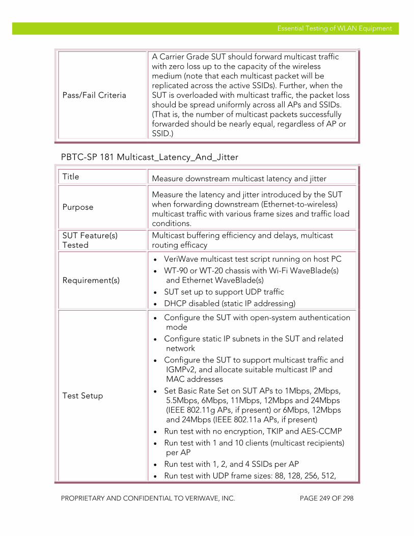
VeriWave, Inc. Essential Testing of WLAN Equipment
PROPRIETARY AND CONFIDENTIAL TO VERIWAVE, INC. PAGE 249 OF 298
Essential Testing of WLAN Equipment
Pass/Fail Criteria
A Carrier Grade SUT should forward multicast traffic with zero loss up to the capacity of the wireless medium (note that each multicast packet will be replicated across the active SSIDs). Further, when the SUT is overloaded with multicast traffic, the packet loss should be spread uniformly across all APs and SSIDs. (That is, the number of multicast packets successfully forwarded should be nearly equal, regardless of AP or SSID.)
PBTC-SP 181 Multicast_Latency_And_Jitter
Title Measure downstream multicast latency and jitter
Purpose
Measure the latency and jitter introduced by the SUT when forwarding downstream (Ethernet-to-wireless) multicast traffic with various frame sizes and traffic load conditions.
SUT Feature(s) Tested
Multicast buffering efficiency and delays, multicast routing efficacy
Requirement(s)
• VeriWave multicast test script running on host PC • WT-90 or WT-20 chassis with Wi-Fi WaveBlade(s)
and Ethernet WaveBlade(s) • SUT set up to support UDP traffic • DHCP disabled (static IP addressing)
Test Setup
• Configure the SUT with open-system authentication mode
• Configure static IP subnets in the SUT and related network
• Configure the SUT to support multicast traffic and IGMPv2, and allocate suitable multicast IP and MAC addresses
• Set Basic Rate Set on SUT APs to 1Mbps, 2Mbps, 5.5Mbps, 6Mbps, 11Mbps, 12Mbps and 24Mbps (IEEE 802.11g APs, if present) or 6Mbps, 12Mbps and 24Mbps (IEEE 802.11a APs, if present)
• Run test with no encryption, TKIP and AES-CCMP • Run test with 1 and 10 clients (multicast recipients)
per AP • Run test with 1, 2, and 4 SSIDs per AP • Run test with UDP frame sizes: 88, 128, 256, 512,

VeriWave, Inc. Essential Testing of WLAN Equipment
PROPRIETARY AND CONFIDENTIAL TO VERIWAVE, INC. PAGE 250 OF 298
Essential Testing of WLAN Equipment
1024, 1280 and 1518 bytes • Run test with source multicast traffic load of 100 to
400 frames/second in steps of 100 frames/second
Procedure
1. Configure the multicast forwarding rate test script according to the trial being run, as per steps 2 through 6
2. Configure the test port(s) (i.e., APs in SUT) and channel(s) to use for the test
3. Configure the multicast traffic parameters to successively send 88, 128, 256, 512, 1024, 1280 and 1518 byte frames (7 values), with traffic loads for each frame size ranging from 100 frames/second to 400 frames/second in steps of 100 frames/second (4 values)
4. Configure 1 Ethernet multicast source client with static IP addressing on the appropriate Ethernet port, and enable IGMP
5. Configure the multicast IP address and MAC address to use for the flow as per the SUT multicast forwarding configuration
6. Configure a single WLAN network (SSID) with open security (no encryption)
7. Configure 1 Wi-Fi client with static IP addressing and using the SSID(s) configured, distributing the client(s) uniformly across the active SSID(s)
8. Run the test by executing the script
9. Wait until the test completes and the results have been written
10. Save the multicast min/max/average latency and smoothed interarrival jitter results
11. Repeat steps 8 through 10 with 10 clients configured per AP and acting as multicast recipients
12. Repeat steps 7 through 11 with 2 and 4 SSIDs per AP; distribute the clients per AP as uniformly as possible across the configured SSIDs
13. Repeat steps 7 through 12 with WPA-TKIP and WPA2-AES encryption/authentication modes
Test Priority High

VeriWave, Inc. Essential Testing of WLAN Equipment
PROPRIETARY AND CONFIDENTIAL TO VERIWAVE, INC. PAGE 251 OF 298
Essential Testing of WLAN Equipment
Test Type Multicast
Pass/Fail Criteria
A Carrier Grade SUT should forward multicast traffic with latency less than 50 msec and jitter less than 10 msec. Further, the latency distribution should be uniform across all of the SUT ports (i.e., APs).
Client Association Rate The client association rate tests determine how well the SUT can support large numbers of concurrently associating clients (i.e., many clients trying to connect to APs in the SUT at the same time). Most WLAN tests assume a steady-state level of client load, and connect all the clients before starting the test. However, a real-life network can be subjected to bursts of client connection attempts – for example, if an AP supporting a number of clients goes down, then all clients connected to the failed AP will simultaneously try to switch to a nearby or secondary AP, causing a burst load on the system. As another example, a power glitch can cause all client connections to be dropped, and every client will then attempt to reconnect before TCP or application layer protocol timers expire. Inability of the system to respond well to bursts of client connections results in lost user sessions and dropped handset calls.
The client association rate test is conducted iteratively until the maximum capacity of the SUT is reached, defined as the rate beyond which the SUT fails to successfully connect one or more clients. The test is performed with different numbers of clients and security modes, as well as with DHCP on and off. In the latter case, this also tests the capacity of the SUT and DHCP server to interwork well.
PBTC-SP 200 Max_Client_Association_Rate_DHCP
Title Measure maximum client association rate with DHCP active
Purpose
Measure the maximum rate at which WLAN clients can successfully associate with the SUT under various security settings and with DHCP being used. The client pool is continuously associated and re-associated with the SUT during the entire duration of each trial in order to assure a steady-state measurement unaffected by artificial factors such as the amount of buffering in the SUT.
SUT Feature(s) Tested
Sustained client connection rate, security state update rate, DHCP transaction completion rate and efficiency
Requirement(s) • WaveApps application running on host PC
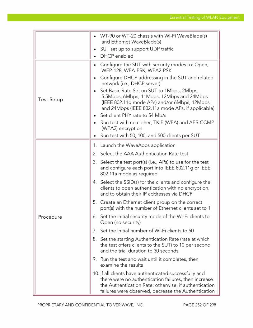
VeriWave, Inc. Essential Testing of WLAN Equipment
PROPRIETARY AND CONFIDENTIAL TO VERIWAVE, INC. PAGE 252 OF 298
Essential Testing of WLAN Equipment
• WT-90 or WT-20 chassis with Wi-Fi WaveBlade(s) and Ethernet WaveBlade(s)
• SUT set up to support UDP traffic • DHCP enabled
Test Setup
• Configure the SUT with security modes to: Open, WEP-128, WPA-PSK, WPA2-PSK
• Configure DHCP addressing in the SUT and related network (i.e., DHCP server)
• Set Basic Rate Set on SUT to 1Mbps, 2Mbps, 5.5Mbps, 6Mbps, 11Mbps, 12Mbps and 24Mbps (IEEE 802.11g mode APs) and/or 6Mbps, 12Mbps and 24Mbps (IEEE 802.11a mode APs, if applicable)
• Set client PHY rate to 54 Mb/s • Run test with no cipher, TKIP (WPA) and AES-CCMP
(WPA2) encryption • Run test with 50, 100, and 500 clients per SUT
Procedure
1. Launch the WaveApps application
2. Select the AAA Authentication Rate test
3. Select the test port(s) (i.e., APs) to use for the test and configure each port into IEEE 802.11g or IEEE 802.11a mode as required
4. Select the SSID(s) for the clients and configure the clients to open authentication with no encryption, and to obtain their IP addresses via DHCP
5. Create an Ethernet client group on the correct port(s) with the number of Ethernet clients set to 1
6. Set the initial security mode of the Wi-Fi clients to Open (no security)
7. Set the initial number of Wi-Fi clients to 50
8. Set the starting Authentication Rate (rate at which the test offers clients to the SUT) to 10 per second and the trial duration to 30 seconds
9. Run the test and wait until it completes, then examine the results
10. If all clients have authenticated successfully and there were no authentication failures, then increase the Authentication Rate; otherwise, if authentication failures were observed, decrease the Authentication

VeriWave, Inc. Essential Testing of WLAN Equipment
PROPRIETARY AND CONFIDENTIAL TO VERIWAVE, INC. PAGE 253 OF 298
Essential Testing of WLAN Equipment
rate
11. Repeat steps 9 and 10 until the maximum Authentication Rate without failures is found
12. Collect report and results data for the maximum Authentication Rate
13. Repeat steps 8 to 12 with 100 and 500 clients configured on the Wi-Fi side
14. Repeat steps 7 to 13 with WEP-128, WPA-PSK, WPA2-PSK security modes
Test Priority Mandatory
Test Type Performance
Pass/Fail Criteria
A Carrier Grade SUT should support an association rate with DHCP-assigned addresses of at least 20 clients/second, in order to assure network availability during burst load or network recovery periods.
System and Stress Testing This section covers test cases conducted on a fully integrated system with all operational components ready so as to evaluate the system’s compliance with specific system-level requirements. The test cases seek to demonstrate the SUT’s ability to support specific real-world operational loads, and thereby detect defects both within the inter-component interfaces and also within the system as a whole. The results either indicate if the SUT passes or fails to meet specific conditions. A passing test result indicates that SUT is capable of operating effectively under those deployment conditions.
System Resiliency and Availability It is highly necessary for the SUT to able to function with high availability as part of the larger network. Availability is comprised of many factors: rapid recovery from system reboots and power cycles, use of redundant elements to lower or eliminate downtime, use of routing algorithms in meshes to route around failure points, and isolation of faults and overloads to maintain service to unaffected portions of the network. In all cases, it is essential that the SUT (whether mesh network or AP/controller system) be able to withstand sudden failures such as AP outages, controller failovers, link failures, etc.

VeriWave, Inc. Essential Testing of WLAN Equipment
PROPRIETARY AND CONFIDENTIAL TO VERIWAVE, INC. PAGE 254 OF 298
Essential Testing of WLAN Equipment
OFTC-SP 001 Mesh_Recovery
Title Test mesh node failure detection and dynamic re-route
Purpose
Cause a mesh node failure situation to occur in the mesh SUT, and measure the time taken to reroute around the failure point as well as the number of dropped client connections that occur while the mesh system re-establishes connectivity.
SUT Feature(s) Tested
Availability, reroute speed, connection maintenance, reliability
Requirement(s)
• WaveApps and WaveVCE applications running on host PC
• WT-90 or WT-20 chassis with Wi-Fi WaveBlades and Ethernet WaveBlade(s)
• VeriWave Backhaul Load and Obstruction Generator (BLOG) application running on one of the Wi-Fi WaveBlades
• Mesh SUT set up to support UDP traffic • Both DHCP and static IP addressing enabled, with
DHCP server available for supplying IP addresses
Test Setup
• Configure the SUT in mesh configuration with at least four access points (to provide a redundant path)
• Configure the SUT with open authentication • Connect the BLOG WaveBlade to an AP in the
primary mesh path using the recommended RF setup
• Set Basic Rate Set on SUT APs to 1Mbps, 2Mbps, 5.5Mbps, 6Mbps, 11Mbps, 12Mbps and 24Mbps (IEEE 802.11g APs) or 6Mbps, 12Mbps and 24Mbps (IEEE 802.11a APs, if applicable)
• Set client PHY rate to 54 Mb/s • Run test with DHCP and static IP addressing • Run test with no cipher, WPA-TKIP and WPA2-AES • Run test with frame sizes: 88, 128, 256, 512, 1024,
1280 and 1518 bytes • Run test with traffic loads of: 25%, 50% and 75% of
measured aggregate throughput • Run test with 10, 20, 100 and 500 total active clients • Run test with UDP and TCP traffic types

VeriWave, Inc. Essential Testing of WLAN Equipment
PROPRIETARY AND CONFIDENTIAL TO VERIWAVE, INC. PAGE 255 OF 298
Essential Testing of WLAN Equipment
Procedure
14. Measure and record the aggregate bidirectional mesh throughput for UDP and stateful TCP traffic using test cases PBTC 108 and PBTC 111
15. Launch the WaveVCE application
16. Select the Mesh Failure Recovery Test under the Wireless Mesh Test Suite
17. Select the test port(s) (i.e., APs) to use for the test and configure into IEEE 802.11g or IEEE 802.11a mode as required; also select and configure the BLOG port
18. Select SSID and configure the clients to open authentication with no encryption, and to obtain IP addresses via static IP addressing
19. Create an Ethernet client group on the correct port(s) with the initial number of Ethernet clients set to 1
20. Set the initial number of Wi-Fi clients to 1; ensure that no clients are connected to the AP which will be brought down by the BLOG port
21. Set the initial frame size to 88 bytes and select UDP traffic type
22. Set the initial aggregate traffic load to 25% of the bidirectional mesh throughput measured for UDP traffic of 88 byte frame size in step 1
23. Select Mesh Hops to Mesh Gateway traffic mapping with bidirectional mode
24. Set the trial duration to 30 seconds and configure the BLOG interference event to occur in the middle of each trial (i.e., at 15 seconds) with a total duration of 2 seconds
25. Run the test
26. Wait until test completes
27. Collect report and results data
28. Repeat steps 10 to 14 with aggregate traffic loads of 50% and 75% of measured throughput
29. Repeat steps 9 to 15 with frame sizes of 128, 256, 512, 1024, 1280 and 1518 bytes
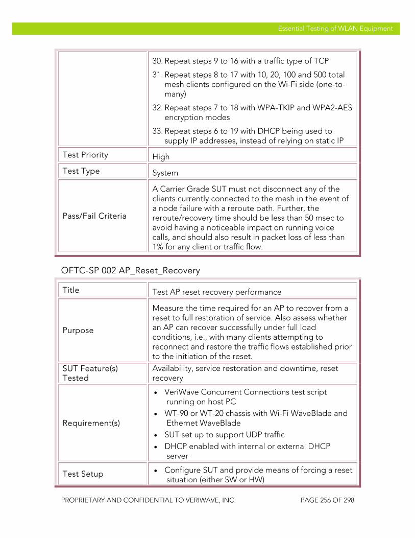
VeriWave, Inc. Essential Testing of WLAN Equipment
PROPRIETARY AND CONFIDENTIAL TO VERIWAVE, INC. PAGE 256 OF 298
Essential Testing of WLAN Equipment
30. Repeat steps 9 to 16 with a traffic type of TCP
31. Repeat steps 8 to 17 with 10, 20, 100 and 500 total mesh clients configured on the Wi-Fi side (one-to-many)
32. Repeat steps 7 to 18 with WPA-TKIP and WPA2-AES encryption modes
33. Repeat steps 6 to 19 with DHCP being used to supply IP addresses, instead of relying on static IP
Test Priority High
Test Type System
Pass/Fail Criteria
A Carrier Grade SUT must not disconnect any of the clients currently connected to the mesh in the event of a node failure with a reroute path. Further, the reroute/recovery time should be less than 50 msec to avoid having a noticeable impact on running voice calls, and should also result in packet loss of less than 1% for any client or traffic flow.
OFTC-SP 002 AP_Reset_Recovery
Title Test AP reset recovery performance
Purpose
Measure the time required for an AP to recover from a reset to full restoration of service. Also assess whether an AP can recover successfully under full load conditions, i.e., with many clients attempting to reconnect and restore the traffic flows established prior to the initiation of the reset.
SUT Feature(s) Tested
Availability, service restoration and downtime, reset recovery
Requirement(s)
• VeriWave Concurrent Connections test script running on host PC
• WT-90 or WT-20 chassis with Wi-Fi WaveBlade and Ethernet WaveBlade
• SUT set up to support UDP traffic • DHCP enabled with internal or external DHCP
server
Test Setup • Configure SUT and provide means of forcing a reset situation (either SW or HW)

VeriWave, Inc. Essential Testing of WLAN Equipment
PROPRIETARY AND CONFIDENTIAL TO VERIWAVE, INC. PAGE 257 OF 298
Essential Testing of WLAN Equipment
• Set Basic Rate Set on SUT AP to 1Mbps, 2Mbps, 5.5Mbps, 6Mbps, 11Mbps, 12Mbps and 24Mbps (IEEE 802.11g mode) and/or 6Mbps, 12Mbps and 24Mbps (IEEE 802.11a mode, if applicable)
• Set client data PHY rate to 54 Mb/s and management PHY rate to 6 Mb/s
• Set test traffic data frame size to 512 bytes with aggregate traffic load of 1000 frames/second
• Run test with 10, 50, 100, and 200 clients on the AP • Run test with 1, 2, and 4 SSIDs configured • Run test with SUT security modes of: Open, WPA-
PSK, WPA2-PSK • Run test with static IP subnets in the SUT and
related network, as well as with DHCP enabled
Procedure
1. Configure the Concurrent Connections test script according to the trial being run, as per steps 2 through 7
2. Configure the test port (i.e., the AP in the SUT that is to be reset) and channel to use for the test
3. Configure the data traffic parameters to send 512 byte frames at an aggregate traffic load of 1000 frames/second per AP
4. Configure 1 Ethernet client with static IP addressing on the appropriate Ethernet port
5. Configure 1 active SSID (i.e., WLAN network) with open security (no encryption)
6. Configure 10 Wi-Fi clients with static IP addressing, all using the SSID configured
7. Configure the trial duration for 300 seconds
8. Start the test by running the script
9. After approximately 30 seconds of traffic, reset the AP in the SUT by either forcing a software or hardware reset, or by disconnecting it from power
10. Hold the reset for 1 second (if induced by hardware or power disconnection) and then remove the reset condition
11. Wait until the test completes and the results have been written

VeriWave, Inc. Essential Testing of WLAN Equipment
PROPRIETARY AND CONFIDENTIAL TO VERIWAVE, INC. PAGE 258 OF 298
Essential Testing of WLAN Equipment
12. Repeat steps 7 through 11 with 50, 100 and 200 clients
13. Repeat steps 6 through 12 with the clients distributed evenly across 2 and 4 SSIDs rather than assigned to a single SSID (all SSIDs having the same parameters)
14. Repeat steps 6 through 13 with SUT security modes of: Open, WPA-PSK, WPA2-PSK
15. Repeat steps 6 through 14 with DHCP enabled and being used to supply IP addresses
Test Priority High
Test Type System
Pass/Fail Criteria
A Carrier Grade SUT must recover from a WLAN controller reset in less than 300 seconds, must successfully reconnect all the clients originally connected to it, and must restore their traffic connections to the level existing prior to the reset. After recovery, the SUT should not show any instabilities or repeated self-resets under load.
Traffic Variation It is expected that the SUT will continue to provide high performance in spite of continuously changing network load conditions. Examples of such load conditions are data overloads and high-load roaming situations. A carrier-grade SUT must have adequate capacity and isolation between SSIDs and service classes in order to provide good service to clients in one portion of the network while overloads and stresses are occurring in another portion. These tests should be run on SUTs having 10 or more APs attached to one or more WLAN controllers. Smaller-scale SUTs are not usually representative of situations occurring in deployed networks where load isolation is critical.
TVTC-SP 001 Data_Load_Isolation
Title Test ability of SUT to isolate data traffic overloads
Purpose
Determine whether the SUT can prevent traffic overloads and congestion situations occurring on one portion of the SUT from affecting normal traffic flowing through another portion of the SUT.
SUT Feature(s) Reliability, service and traffic isolation, QoS

VeriWave, Inc. Essential Testing of WLAN Equipment
PROPRIETARY AND CONFIDENTIAL TO VERIWAVE, INC. PAGE 259 OF 298
Essential Testing of WLAN Equipment
Tested
Requirement(s)
• VeriWave WaveApps running on host PC (two instances)
• WT-90 or WT-20 chassis with at least 10 Wi-Fi WaveBlades and 2 Ethernet WaveBlades
• SUT with at least 10 APs set up to support UDP traffic and static IP addresses
Test Setup
• Configure the SUT with open-system authentication mode
• Set Basic Rate Set on SUT AP to 1Mbps, 2Mbps, 5.5Mbps, 6Mbps, 11Mbps, 12Mbps and 24Mbps (IEEE 802.11g) and/or 6Mbps, 12Mbps and 24Mbps (IEEE 802.11a APs, if applicable)
• Set client data PHY rate to 54 Mb/s and management PHY rate to 6 Mb/s
• Set overload traffic to UDP, 256 bytes, and ILOAD of 10000 frames/second per AP
• Run test with UDP test traffic frame sizes: 88, 128, 256, 512, 1024, 1280 and 1518 bytes
• Run test with: 10, 50, 100, and 200 clients per AP • Run test with SUT security modes of: Open, WPA-
PSK (TKIP), WPA2-PSK (AES-CCMP)
Procedure
16. Measure the downstream UDP throughput of the SUT for each of the test traffic frame sizes (i.e., 88, 128, 256, 512, 1024, 1280 and 1518 bytes) using the WaveApps throughput test, and record these values
17. Launch the first instance of the WaveApps application, to serve as the test traffic generator and analysis function
18. Select the Packet Loss Test under the IEEE 802.11.2 Benchmark Test Suite
19. Select a subset of the test ports (i.e., APs) to use for the test traffic; one of the Ethernet ports, and at least 40% and no more than 60% of the available APs in the SUT should be devoted to carrying test traffic
20. Select the SSID to use, and configure the Wi-Fi clients to open authentication with no encryption and static IP addressing

VeriWave, Inc. Essential Testing of WLAN Equipment
PROPRIETARY AND CONFIDENTIAL TO VERIWAVE, INC. PAGE 260 OF 298
Essential Testing of WLAN Equipment
21. Set the initial number of Wi-Fi clients to 10 (and the corresponding number of Ethernet clients)
22. Select the initial frame size as 88 bytes, UDP traffic type, the ILOAD of the test traffic to 90% of the measured aggregate throughput at the configured frame size, and the trial duration to 30 seconds
23. Select Ethernet to Wireless (one-to-one, downstream) mapping
24. Launch the second instance of the WaveApps application (on the same or a different host PC), to serve as the overload traffic generator
25. Select the Packet Loss Test
26. Select the remaining APs in the SUT to serve as test ports, along with a second Ethernet port
27. Select the SSID and configure the Wi-Fi clients to open authentication with no encryption and static IP addressing
28. Set the number of Wi-Fi clients to 1 (with the corresponding number of Ethernet clients
29. Set the frame size to 256 bytes, UDP traffic type, the ILOAD to 10000 frames/second per overloaded AP in SUT, the trial duration to 10 seconds, the number of trials to 30, and the settling time between trials to 5 seconds
30. Select Ethernet to Wireless (downstream) mapping
31. Start the overload traffic (i.e., the second instance of the WaveApps application)
32. After 10 seconds, start the test traffic (i.e., the first instance of the WaveApps application)
33. Wait until both instances complete
34. Collect the report and results data for the test traffic
35. Repeat steps 7 to 19 with 50, 100, and 200 clients per AP configured on both Ethernet and Wi-Fi sides (one-to-one) in the test traffic application
36. Repeat steps 6 to 20 with WPA-TKIP and WPA2-AES encryption modes
Test Priority Mandatory

VeriWave, Inc. Essential Testing of WLAN Equipment
PROPRIETARY AND CONFIDENTIAL TO VERIWAVE, INC. PAGE 261 OF 298
Essential Testing of WLAN Equipment
Test Type System
Pass/Fail Criteria
A Carrier Grade SUT should show zero packet loss experienced by the test traffic, regardless of the level of overload being experienced by the other APs in the SUT.
TVTC-SP 002 Roaming_Isolation_Network
Title Test ability of SUT to isolate roaming loads between different physical parts of the WLAN
Purpose
Determine whether the SUT can prevent roaming overload situations occurring on one portion of the SUT from affecting normal roaming clients on another portion of the SUT.
SUT Feature(s) Tested
Reliability, service and roaming isolation, QoS
Requirement(s)
• VeriWave WaveApps running on host PC (two instances)
• WT-90 or WT-20 chassis with at least 10 Wi-Fi WaveBlades and 2 Ethernet WaveBlades
• SUT with at least 10 APs set up to support UDP traffic
• DHCP server
Test Setup
• Configure the SUT with open-system authentication mode and supporting both DHCP and static IP addressing
• Set Basic Rate Set on SUT AP to 1Mbps, 2Mbps, 5.5Mbps, 6Mbps, 11Mbps, 12Mbps and 24Mbps (IEEE 802.11g APs) and/or 6Mbps, 12Mbps and 24Mbps (IEEE 802.11a APs, if applicable)
• Set client data PHY rate to 54 Mb/s and management PHY rate to 6 Mb/s
• Configure 100 overload roaming clients roaming at a rate of 30 roams/second
• Run test with: 10, 50, 100 and 500 test roaming clients (for the SUT) roaming at a rate of 0.5 roams/second
• Run test with SUT security modes of: Open (no security), WPA-PSK WPA2-PSK

VeriWave, Inc. Essential Testing of WLAN Equipment
PROPRIETARY AND CONFIDENTIAL TO VERIWAVE, INC. PAGE 262 OF 298
Essential Testing of WLAN Equipment
Procedure
1. Measure the roaming delay and failed roams of the SUT for each of the counts of roaming clients (i.e., 10, 50, 100 and 500) at a roaming rate of 0.5 roams/second using the WaveApps Roaming Benchmark test, and record these values
2. Launch the first instance of the WaveApps application, to serve as the test roaming generator and analysis function
3. Select the Roaming Benchmark Test under the WLAN Roaming Test Suite
4. Select a subset of the test ports (i.e., APs) to use for the test roaming generator; one of the Ethernet ports, and at least 40% and no more than 60% of the available APs in the SUT should be devoted to supporting test roaming clients
5. Select the SSID to use, configure the Wi-Fi clients to Open security with DHCP, and create an Ethernet client group on the correct port
6. Set the initial number of test roaming clients to 10
7. Set the roam sequence to roam all clients uniformly across all the port subset, with a uniform initial client distribution, set the initial roaming rate to 0.5 roams/second (for the entire SUT), and set the test duration to 300 seconds
8. Set the data traffic flow to a frame size of 256 bytes and a flow rate of 100 pps (per client)
9. Launch the second instance of the WaveApps application (on the same or a different host PC), to serve as the overload roaming generator
10. Select the Roaming Benchmark Test under the WLAN Roaming Test Suite
11. Select the remaining APs in the SUT to serve as overload roaming ports, along with a second Ethernet port for traffic injection
12. Select the SSID to use, configure the Wi-Fi clients to WPA2-PSK security with static IP addressing, and set the number of overload roaming clients to 10; set the data traffic flow to a frame size of 256 bytes and a flow rate of 100 pps (per client)

VeriWave, Inc. Essential Testing of WLAN Equipment
PROPRIETARY AND CONFIDENTIAL TO VERIWAVE, INC. PAGE 263 OF 298
Essential Testing of WLAN Equipment
13. Set the roam sequence to roam all clients uniformly across all the port subset at a rate of 30 roams/second, and set the test duration to 240 seconds
14. Start the test roaming traffic (i.e., the first instance of the WaveApps application)
15. After 10 seconds, start the overload roaming traffic (i.e., the second instance of the WaveApps application)
16. Wait until both instances complete
17. Collect the report and results data for the test roaming clients
18. Repeat steps 7 to 19 with 50, 100, 200 and 500 total clients configured for the test roaming traffic application
19. Repeat steps 6 to 20 with WPA-PSK, WPA2-PSK security modes for the test roaming traffic clients
Test Priority High
Test Type System
Pass/Fail Criteria
A Carrier Grade SUT should show no change in roaming delays or failures experienced by the test roaming traffic, regardless of the level of roaming overload being experienced by the other APs in the SUT.
WiMix Tests The WiMix traffic tests verify operation of the SUT under real-world traffic loading scenarios. The scenarios explore various vertical application situations: hospitals, enterprises, universities and retail organizations, as well as combined voice, video and data cases that are common to access and carrier networks. The goal of these test cases is to subject the SUT to combinations of traffic flows and client types commonly found in real environments and determine if the SUT can support these mixes efficiently, and without failing the basic QoS requirements for each type of client or traffic flow. Each of these test cases should be run on a SUT that constitutes a minimum of 10 APs and one WLAN controller, to provide a representative example of an actual small-scale installation. It is strongly recommended, however, that these test cases be performed with larger SUTs (25 – 100 APs and 2 or more controllers) to

VeriWave, Inc. Essential Testing of WLAN Equipment
PROPRIETARY AND CONFIDENTIAL TO VERIWAVE, INC. PAGE 264 OF 298
Essential Testing of WLAN Equipment
gain a true picture of the SUT behavior in the large deployments where application-level performance is critical.
WMTC-SP 001 WiMix_Triple_Play_Unicast
Title Demonstrate support level of the SUT for mixed voice, unicast video and data traffic streams
Purpose
Assess the ability of the SUT to support triple-play traffic mixes (voice, unicast video and data) using a customized WiMix traffic profile. Such traffic mixes are commonly found in service provider, consumer wireless access, and enterprise multimedia situations. The SUT is subjected to these traffic mixes and different application-specific metrics (loss/latency for data, R-values for voice, and MDI scores for video) are measured to determine the support level of the SUT.
SUT Feature(s) Tested
QoS maintenance, triple-play traffic, voice, unicast video
Requirement(s)
• WaveVCE application running on host PC • WT-90 or WT-20 chassis with 10 or more Wi-Fi
WaveBlades and 1 or more Ethernet WaveBlade(s) • SUT with 10 or more APs set up to support UDP,
TCP, voice and video traffic • DHCP server
Test Setup
• Connect the Wi-Fi WaveBlades to the SUT APs • Configure at least 2 SSIDs on the SUT (one for
voice, the other for data/video) with appropriate VLANs on the Ethernet side; 3 SSIDs are preferred, so that data, voice and video may be properly separated
• Configure the voice SSID to use WEP-128 security mode
• Configure the video SSID (if present) to use WPA-PSK security mode
• Configure desired QoS parameters for data, voice and video on the SUT
• Set Basic Rate Set on SUT APs to 1Mbps, 2Mbps, 5.5Mbps, 6Mbps, 11Mbps, 12Mbps and 24Mbps (IEEE 802.11g APs) or 6Mbps, 12Mbps and 24Mbps (IEEE 802.11a APs, if present)
• Set client flow PHY rate to 54 Mb/s and
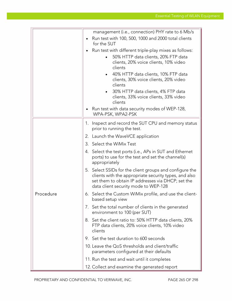
VeriWave, Inc. Essential Testing of WLAN Equipment
PROPRIETARY AND CONFIDENTIAL TO VERIWAVE, INC. PAGE 265 OF 298
Essential Testing of WLAN Equipment
management (i.e., connection) PHY rate to 6 Mb/s • Run test with 100, 500, 1000 and 2000 total clients
for the SUT • Run test with different triple-play mixes as follows:
• 50% HTTP data clients, 20% FTP data clients, 20% voice clients, 10% video clients
• 40% HTTP data clients, 10% FTP data clients, 30% voice clients, 20% video clients
• 30% HTTP data clients, 4% FTP data clients, 33% voice clients, 33% video clients
• Run test with data security modes of WEP-128, WPA-PSK, WPA2-PSK
Procedure
1. Inspect and record the SUT CPU and memory status prior to running the test.
2. Launch the WaveVCE application
3. Select the WiMix Test
4. Select the test ports (i.e., APs in SUT and Ethernet ports) to use for the test and set the channel(s) appropriately
5. Select SSIDs for the client groups and configure the clients with the appropriate security types, and also set them to obtain IP addresses via DHCP; set the data client security mode to WEP-128
6. Select the Custom WiMix profile, and use the client-based setup view
7. Set the total number of clients in the generated environment to 100 (per SUT)
8. Set the client ratio to: 50% HTTP data clients, 20% FTP data clients, 20% voice clients, 10% video clients
9. Set the test duration to 600 seconds
10. Leave the QoS thresholds and client/traffic parameters configured at their defaults
11. Run the test and wait until it completes
12. Collect and examine the generated report

VeriWave, Inc. Essential Testing of WLAN Equipment
PROPRIETARY AND CONFIDENTIAL TO VERIWAVE, INC. PAGE 266 OF 298
Essential Testing of WLAN Equipment
13. Repeat steps 9 to 12 with client ratios of: 40% HTTP data clients, 10% FTP data clients, 30% voice clients, 20% video clients; and 30% HTTP data clients, 4% FTP data clients, 33% voice clients, 33% video clients
14. Repeat steps 8 to 13 with 500, 1000 and 2000 clients for the SUT
15. Repeat steps 6 to 14 with data security modes of WPA-PSK and WPA2-PSK
16. Inspect the SUT CPU and memory status after all the trials have been completed and compare to the initial status
Test Priority Medium
Test Type System
Pass/Fail Criteria
A Carrier Grade SUT should be able to support the different client and traffic loads in a Triple-Play situation without loss of stability or progressive degradation in system capacity (e.g., due to memory leaks or CPU overload). Further, all of the voice/video clients and traffic flows should have satisfied their required QoS levels. The latency levels for the data clients should remain under 50 msec.
WMTC-SP 002 WiMix_Triple_Play_Multicast
Title Demonstrate support level of the SUT for mixed voice, unicast video and data traffic streams
Purpose
Assess the ability of the SUT to support triple-play traffic mixes (voice, multicast video and data) using a customized WiMix traffic profile. Such traffic mixes are commonly found in service provider, consumer wireless access, and enterprise multimedia situations. The SUT is subjected to these traffic mixes and different application-specific metrics (loss/latency for data, R-values for voice, and MDI scores for video) are measured to determine the support level of the SUT.
SUT Feature(s) Tested
QoS maintenance, triple-play traffic, voice, multicast video
Requirement(s) • WaveVCE application running on host PC

VeriWave, Inc. Essential Testing of WLAN Equipment
PROPRIETARY AND CONFIDENTIAL TO VERIWAVE, INC. PAGE 267 OF 298
Essential Testing of WLAN Equipment
• WT-90 or WT-20 chassis with 10 or more Wi-Fi WaveBlades and 1 or more Ethernet WaveBlade(s)
• SUT with 10 or more APs set up to support UDP, TCP, voice and video traffic
• DHCP server
Test Setup
• Connect the Wi-Fi WaveBlades to the SUT APs • Configure at least 2 SSIDs on the SUT (one for
voice, the other for data/video) with appropriate VLANs on the Ethernet side; 3 SSIDs are preferred, so that data, voice and video may be properly separated
• Configure the voice SSID to use WEP-128 security mode
• Configure the video SSID (if present) to use WPA-PSK security mode
• Configure a Class D multicast address of 250.0.0.10 to be used as the multicast video target
• Configure desired QoS parameters for data, voice and video on the SUT
• Set Basic Rate Set on SUT APs to 1Mbps, 2Mbps, 5.5Mbps, 6Mbps, 11Mbps, 12Mbps and 24Mbps (IEEE 802.11g APs) or 6Mbps, 12Mbps and 24Mbps (IEEE 802.11a APs, if present)
• Set client flow PHY rate to 54 Mb/s and management (i.e., connection) PHY rate to 6 Mb/s
• Run test with 100, 500, 1000 and 2000 total clients for the SUT
• Run test with different triple-play mixes as follows: • 50% HTTP data clients, 20% FTP data
clients, 20% voice clients, 10% video clients
• 40% HTTP data clients, 10% FTP data clients, 30% voice clients, 20% video clients
• 30% HTTP data clients, 4% FTP data clients, 33% voice clients, 33% video clients
• Run test with data security modes of WEP-128, WPA-PSK, WPA2-PSK
Procedure 1. Inspect and record the SUT CPU and memory status

VeriWave, Inc. Essential Testing of WLAN Equipment
PROPRIETARY AND CONFIDENTIAL TO VERIWAVE, INC. PAGE 268 OF 298
Essential Testing of WLAN Equipment
prior to running the test.
2. Launch the WaveVCE application
3. Select the WiMix Test
4. Select the test ports (i.e., APs in SUT and Ethernet ports) to use for the test and set the channel(s) appropriately
5. Select SSIDs for the client groups and configure the clients with the appropriate security types, and also set them to obtain IP addresses via DHCP; set the data client security mode to WEP-128
6. Select the Custom WiMix profile, and use the client-based setup view
7. Set the total number of clients in the generated environment to 100 (per SUT)
8. Set the client ratio to: 50% HTTP data clients, 20% FTP data clients, 20% voice clients, 10% video clients
9. Configure the multicast video target IP address to 250.0.0.10 (and a corresponding multicast MAC address), and configure the appropriate multicast video server in the WiMix application
10. Set the test duration to 600 seconds
11. Leave the QoS thresholds and client/traffic parameters configured at their defaults
12. Run the test and wait until it completes
13. Collect and examine the generated report
14. Repeat steps 9 to 13 with client ratios of: 40% HTTP data clients, 10% FTP data clients, 30% voice clients, 20% video clients; and 30% HTTP data clients, 4% FTP data clients, 33% voice clients, 33% video clients
15. Repeat steps 8 to 14 with 500, 1000 and 2000 clients for the SUT
16. Repeat steps 6 to 15 with data security modes of WPA-PSK and WPA2-PSK
17. Inspect the SUT CPU and memory status after all the trials have been completed and compare to the initial status

VeriWave, Inc. Essential Testing of WLAN Equipment
PROPRIETARY AND CONFIDENTIAL TO VERIWAVE, INC. PAGE 269 OF 298
Essential Testing of WLAN Equipment
Test Priority Medium
Test Type System
Pass/Fail Criteria
A Carrier Grade SUT should be able to support the different client and traffic loads in a Triple-Play situation without loss of stability or progressive degradation in system capacity (e.g., due to memory leaks or CPU overload). Further, all of the voice/video clients and traffic flows should have satisfied their required QoS levels. The latency levels for the data clients should remain under 50 msec.
Mesh Interference Effects It is expected that mesh SUTs will handle interference and continue to maintain availability and performance to sections of the mesh that are not directly impacted by the interference. For example, if interference brings down one link, then the mesh routing algorithms are expected to discover a path around the interference and restore service to the affected portions. These test cases therefore assess the ability of a mesh SUT to cope with limited or catastrophic interference conditions, and continue to maintain service to associated WLAN clients. These test cases must be run on mesh SUTs containing a minimum of 4 mesh APs (preferably more), organized in such a way as to provide a backup path around the link on which interference is applied. Care must be taken to ensure that the backup path acts as a secondary rather than a primary data path (i.e., it is only used when the primary path is subjected to interference).
IETC-SP 001 Mesh_Interference_Reroute
Title Assess impact on data traffic during mesh reroute events
Purpose
Measure the restoration time required by a WLAN mesh SUT when a catastrophic interference situation on the backhaul channel of a mesh AP causes the mesh routing protocols to reroute traffic. The packet loss during the reroute process is also measured.
SUT Feature(s) Tested
Mesh routing protocol performance, reroute delay, reroute packet loss, route convergence time, routing algorithm stability
Requirement(s) • WaveVCE application running on host PC • WT-90 or WT-20 chassis with Wi-Fi WaveBlade(s)

VeriWave, Inc. Essential Testing of WLAN Equipment
PROPRIETARY AND CONFIDENTIAL TO VERIWAVE, INC. PAGE 270 OF 298
Essential Testing of WLAN Equipment
and Ethernet WaveBlade(s) • Mesh SUT set up to support UDP traffic • DHCP server
Test Setup
• Configure the SUT in mesh configuration with at least four access points, set up to provide primary and backup backhaul paths
• Configure the SUT with open authentication and DHCP enabled
• Set Basic Rate Set on SUT to 1Mbps, 2Mbps, 5.5Mbps, 6Mbps, 11Mbps, 12Mbps and 24Mbps (IEEE 802.11g APs) or 6Mbps, 12Mbps and 24Mbps (IEEE 802.11a APs, if applicable)
• Set intended load (ILOAD) for each frame size to 90% of the throughput of the SUT as obtained from the mesh per-hop throughput tests (if the SUT throughput is unknown, use theoretical values)
• Set BLOG interference parameters to: 100% injection rate, frame sizes from 64 bytes to 1518 bytes, begin time of 50% of trial duration, end time of 100% of trial duration
• Set client PHY rate to 54 Mb/s, and set clients to use DHCP to obtain IP addresses
• Set trial duration to 60 seconds • Run test with 1, 10, 20, and 100 clients per mesh AP • Run test with no cipher, WPA-TKIP and WPA2-AES • Run test with frame sizes: 88, 512, 1024 and 1518
bytes
Procedure
14. Launch the WaveVCE application
15. Select the Mesh Reconfiguration Test under the Mesh Test Suite
16. Select the test port(s) (i.e., APs) to use for the data traffic portion of the test and configure into IEEE 802.11g or IEEE 802.11a mode as required
17. Select the test port to use as a Backhaul Load and Obstruction Generator (BLOG) and configure as above
18. Select SSID and configure the clients to open authentication with no encryption and obtain IP addresses via DHCP

VeriWave, Inc. Essential Testing of WLAN Equipment
PROPRIETARY AND CONFIDENTIAL TO VERIWAVE, INC. PAGE 271 OF 298
Essential Testing of WLAN Equipment
19. Create an Ethernet client group on the correct port(s) with the number of Ethernet clients set to 1 per AP
20. Set the initial number of Wi-Fi mesh clients to 1 per AP
21. Select a frame size of 88 bytes and UDP traffic type; set the intended load (ILOAD) to the target traffic load as per above
22. Select Mesh Hops to Mesh Gateway (upstream) mapping
23. Run the test
24. Wait until test completes
25. Collect report and results data
26. Repeat steps 9 to 12 with frame sizes of 512, 1024 and 1518 bytes
27. Repeat steps 8 to 13 with 10, 20, and 100 clients per mesh AP
28. Repeat steps 6 to 14 with WPA-TKIP and WPA2-AES encryption modes
Test Priority High
Test Type System
Pass/Fail Criteria
A high-availability Carrier Grade SUT should not require more than 1 second to reroute traffic from the primary to the backup path from the onset of interference that shuts down an AP in the primary path. Further, the SUT should not lose more than 10% of the packets (as measured over the total trial duration) while doing so.
IETC-SP 002 Mesh_UDP_Throughput_Interference_Impact
Title Assess impact on UDP traffic throughput during high-interference events
Purpose Measure the degradation of client UDP data throughput in a WLAN mesh SUT as the interference level is progressively increased on a backhaul link.
SUT Feature(s) Mesh routing adaptability, interference handling, mesh

VeriWave, Inc. Essential Testing of WLAN Equipment
PROPRIETARY AND CONFIDENTIAL TO VERIWAVE, INC. PAGE 272 OF 298
Essential Testing of WLAN Equipment
Tested stability
Requirement(s)
• WaveVCE application running on host PC • WT-90 or WT-20 chassis with Wi-Fi WaveBlade(s)
and Ethernet WaveBlade(s) • Mesh SUT set up to support UDP traffic • DHCP server
Test Setup
• Configure the SUT in mesh configuration with at least four access points, set up to provide primary and backup backhaul paths
• Configure the SUT with open authentication and DHCP enabled
• Set Basic Rate Set on SUT to 1Mbps, 2Mbps, 5.5Mbps, 6Mbps, 11Mbps, 12Mbps and 24Mbps (IEEE 802.11g APs) or 6Mbps, 12Mbps and 24Mbps (IEEE 802.11a APs, if applicable)
• Set BLOG interference parameters to: all frame sizes from 64 bytes to 1518 bytes, begin time of 0% of trial duration, end time of 100% of trial duration
• Set client PHY rate to 54 Mb/s, and set clients to use DHCP to obtain IP addresses
• Set trial duration to 60 seconds • Run test with 1, 10, 20, and 100 clients per mesh AP • Run test with no cipher, WPA-TKIP and WPA2-AES • Run test with frame sizes: 88, 128, 256, 512, 1024,
1280 and 1518 bytes • Run test with BLOG interference levels of: 10%,
20%, 30%, 40%, 50%, 60%, 70%, and 80%
Procedure
14. Launch the WaveVCE application
15. Select the Mesh Per-Hop Throughput Test under the Wireless Mesh Test Suite
16. Select the test port(s) (i.e., APs) to use for the data traffic and configure into IEEE 802.11g or IEEE 802.11a mode as required
17. Select the test port to use as a Backhaul Load and Obstruction Generator (BLOG) and configure as above
18. Select SSID and configure the clients to open authentication with no encryption and obtain IP addresses via DHCP

VeriWave, Inc. Essential Testing of WLAN Equipment
PROPRIETARY AND CONFIDENTIAL TO VERIWAVE, INC. PAGE 273 OF 298
Essential Testing of WLAN Equipment
19. Create an Ethernet client group on the correct port(s) with the initial number of Ethernet clients set to 1 per mesh AP
20. Set the initial number of Wi-Fi clients to 1 per AP
21. Set the initial BLOG interference level to 10%
22. Select frame sizes of 88, 128, 256, 512, 1024, 1280 and 1518 bytes and UDP traffic type
23. Select Mesh Hops to Mesh Gateway traffic mapping with bidirectional mode
24. Run the test
25. Wait until test completes
26. Collect report and results data
27. Repeat steps 9 to 13 with BLOG interference levels of: 20%, 30%, 40%, 50%, 60%, 70%, and 80%
28. Repeat steps 8 to 14 with 10, 20, and 100 clients configured on both Ethernet and Wi-Fi sides (one-to-one) per mesh AP
29. Repeat steps 6 to 15 with WPA-TKIP and WPA2-AES encryption modes
Test Priority Medium
Test Type System
Pass/Fail Criteria
A robust Carrier Grade SUT should show a graceful degradation of UDP throughput (i.e., a linear decrease with no sharp peaks or troughs) with progressively increasing levels of interference. Ideally, the SUT should also utilize alternate paths to carry data traffic as the level of interference exceeds 50%, in order to ensure that a carrier can use a standard 50% provisioning model to cope with interference impact.
IETC-SP 003 Mesh_Latency_Interference_Impact
Title Assess impact on UDP traffic latency during high-interference events
Purpose Measure degradation of latency experienced by client UDP traffic traversing a WLAN mesh SUT as the

VeriWave, Inc. Essential Testing of WLAN Equipment
PROPRIETARY AND CONFIDENTIAL TO VERIWAVE, INC. PAGE 274 OF 298
Essential Testing of WLAN Equipment
interference level is progressively increased on a specific backhaul link.
SUT Feature(s) Tested
Mesh routing adaptability, interference handling, mesh stability
Requirement(s)
• WaveVCE application running on host PC • WT-90 or WT-20 chassis with Wi-Fi WaveBlade(s)
and Ethernet WaveBlade(s) • Mesh SUT set up to support UDP traffic • DHCP server
Test Setup
• Configure the SUT in mesh configuration with at least four access points, set up to provide primary and backup backhaul paths
• Configure the SUT with open authentication and DHCP enabled
• Set Basic Rate Set on SUT to 1Mbps, 2Mbps, 5.5Mbps, 6Mbps, 11Mbps, 12Mbps and 24Mbps (IEEE 802.11g APs) or 6Mbps, 12Mbps and 24Mbps (IEEE 802.11a APs, if applicable)
• Set BLOG interference parameters to: all frame sizes from 64 bytes to 1518 bytes, begin time of 0% of trial duration, end time of 100% of trial duration
• Set client PHY rate to 54 Mb/s, and set clients to use DHCP to obtain IP addresses
• Set intended load (ILOAD) for each frame size to 90% of the throughput of the SUT as obtained from the mesh per-hop throughput tests (if the SUT throughput is unknown, use theoretical values)
• Set trial duration to 60 seconds • Run test with 1, 10, 20, and 100 clients per mesh AP • Run test with no cipher, WPA-TKIP and WPA2-AES • Run test with frame sizes: 88, 128, 256, 512, 1024,
1280 and 1518 bytes • Run test with BLOG interference levels of: 10%,
20%, 30%, 40%, 50%, 60%, 70%, and 80%
Procedure
1. Launch the WaveVCE application
2. Select the Mesh Per-Hop Latency Test under the Wireless Mesh Test Suite
3. Select the test port(s) (i.e., APs) to use for the data traffic and configure into IEEE 802.11g or IEEE

VeriWave, Inc. Essential Testing of WLAN Equipment
PROPRIETARY AND CONFIDENTIAL TO VERIWAVE, INC. PAGE 275 OF 298
Essential Testing of WLAN Equipment
802.11a mode as required
4. Select the test port to use as a Backhaul Load and Obstruction Generator (BLOG) and configure as above
5. Select SSID and configure the clients to open authentication with no encryption and obtain IP addresses via DHCP
6. Create an Ethernet client group on the correct port(s) with the initial number of Ethernet clients set to 1 per AP
7. Set the initial number of Wi-Fi clients to 1 per AP
8. Set the initial BLOG interference level to 10%
9. Select frame sizes of 88, 128, 256, 512, 1024, 1280 and 1518 bytes and UDP traffic type; adjust the intended load (ILOAD) table to target traffic load as per test setup details above
10. Select Mesh Hops to Mesh Gateway (upstream) traffic mapping
11. Run the test
12. Wait until test completes
13. Collect report and results data
14. Repeat steps 9 to 13 with BLOG interference levels of: 20%, 30%, 40%, 50%, 60%, 70%, and 80%
15. Repeat steps 8 to 14 with 10, 20, and 100 clients configured on both Ethernet and Wi-Fi sides (one-to-one) per mesh AP
16. Repeat steps 6 to 15 with WPA-TKIP and WPA2-AES encryption modes
Test Priority Medium
Test Type System
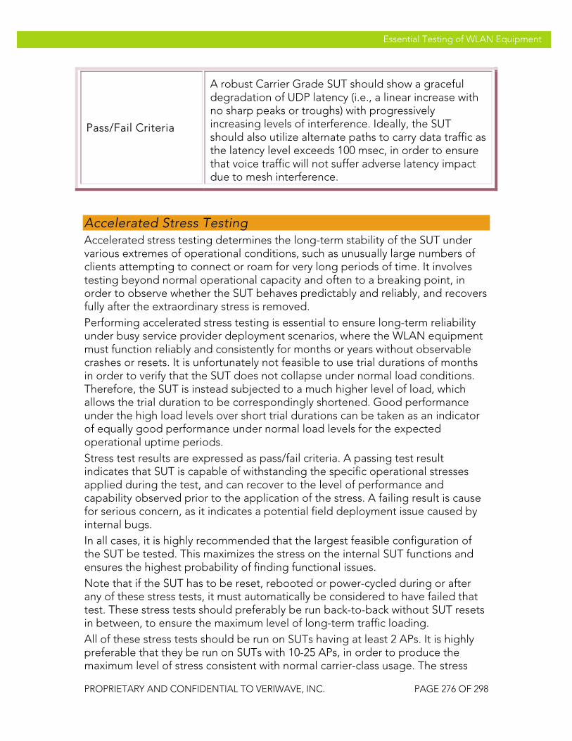
VeriWave, Inc. Essential Testing of WLAN Equipment
PROPRIETARY AND CONFIDENTIAL TO VERIWAVE, INC. PAGE 276 OF 298
Essential Testing of WLAN Equipment
Pass/Fail Criteria
A robust Carrier Grade SUT should show a graceful degradation of UDP latency (i.e., a linear increase with no sharp peaks or troughs) with progressively increasing levels of interference. Ideally, the SUT should also utilize alternate paths to carry data traffic as the latency level exceeds 100 msec, in order to ensure that voice traffic will not suffer adverse latency impact due to mesh interference.
Accelerated Stress Testing Accelerated stress testing determines the long-term stability of the SUT under various extremes of operational conditions, such as unusually large numbers of clients attempting to connect or roam for very long periods of time. It involves testing beyond normal operational capacity and often to a breaking point, in order to observe whether the SUT behaves predictably and reliably, and recovers fully after the extraordinary stress is removed. Performing accelerated stress testing is essential to ensure long-term reliability under busy service provider deployment scenarios, where the WLAN equipment must function reliably and consistently for months or years without observable crashes or resets. It is unfortunately not feasible to use trial durations of months in order to verify that the SUT does not collapse under normal load conditions. Therefore, the SUT is instead subjected to a much higher level of load, which allows the trial duration to be correspondingly shortened. Good performance under the high load levels over short trial durations can be taken as an indicator of equally good performance under normal load levels for the expected operational uptime periods. Stress test results are expressed as pass/fail criteria. A passing test result indicates that SUT is capable of withstanding the specific operational stresses applied during the test, and can recover to the level of performance and capability observed prior to the application of the stress. A failing result is cause for serious concern, as it indicates a potential field deployment issue caused by internal bugs. In all cases, it is highly recommended that the largest feasible configuration of the SUT be tested. This maximizes the stress on the internal SUT functions and ensures the highest probability of finding functional issues. Note that if the SUT has to be reset, rebooted or power-cycled during or after any of these stress tests, it must automatically be considered to have failed that test. These stress tests should preferably be run back-to-back without SUT resets in between, to ensure the maximum level of long-term traffic loading. All of these stress tests should be run on SUTs having at least 2 APs. It is highly preferable that they be run on SUTs with 10-25 APs, in order to produce the maximum level of stress consistent with normal carrier-class usage. The stress

VeriWave, Inc. Essential Testing of WLAN Equipment
PROPRIETARY AND CONFIDENTIAL TO VERIWAVE, INC. PAGE 277 OF 298
Essential Testing of WLAN Equipment
tests use combinations of standard system, functional and performance tests in order to expose hidden SUT problems.
Traffic Stress Any carrier-class SUT must be able to sustain high levels of traffic for very long periods of time without experiencing performance issues due to internal problems such as memory leaks or data structure corruption. The traffic stress test therefore subjects the SUT to a realistic traffic scenario for long periods of time. Throughput and latency measurements are made before and after the traffic stress, in order to verify that permanent degradation in SUT performance has not occurred as a consequence of the traffic stress.
TSTC-SP 001 Traffic_Stress
Title Verify ability of SUT to withstand high levels of mixed data traffic
Purpose
Stresses the SUT with a typical traffic mix (using the WiMix Enterprise profile) for a long duration, to determine if performance changes occur due to internal issues. SUT performance is verified before and after the stress period using standard throughput and latency tests.
SUT Feature(s) Tested
Datapath robustness, buffer management, queue management, scheduling functions, long-term stability
Requirement(s)
• WaveApps and WaveVCE applications running on host PC
• WT-90 chassis with Wi-Fi WaveBlade(s) and Ethernet WaveBlade(s)
• SUT set up to support multiple SSIDs • DHCP enabled with internal or external DHCP
server
Test Setup
• Configure the SUT with security modes on different SSIDs to: Open, WEP-128, WPA-PSK, and WPA2-PSK (Note: if the SUT supports only one active SSID, use only WPA2-PSK security mode and a single SSID)
• Set Basic Rate Set on SUT APs to 1Mbps, 2Mbps, 5.5Mbps, 6Mbps, 11Mbps, 12Mbps and 24Mbps (IEEE 802.11g APs) and/or 6Mbps, 12Mbps and 24Mbps (IEEE 802.11a APs, if applicable)
• Set client PHY rate to 54 Mb/s • Set client security types to match those in the SUT

VeriWave, Inc. Essential Testing of WLAN Equipment
PROPRIETARY AND CONFIDENTIAL TO VERIWAVE, INC. PAGE 278 OF 298
Essential Testing of WLAN Equipment
• Run test with 50 clients per AP in the SUT
Procedure
1. Configure the SUT as indicated above
2. Perform PBTC 001, Upstream_UDP_80211g_Throughput, on all IEEE 802.11g APs in the SUT, and record the results
3. Perform PBTC 002, Downstream_UDP_80211g_Throughput, on all IEEE 802.11g APs in the SUT, and record the results
4. Perform PBTC 004, Upstream_UDP_80211a_Throughput, on all IEEE 802.11a APs in the SUT, and record the results
5. Perform PBTC 005, Downstream_UDP_80211a_Throughput, on all IEEE 802.11a APs in the SUT, and record the results
6. Perform PBTC 020, Upstream_80211g_Packet_Latency, on all IEEE 802.11g APs in the SUT, and record the results
7. Perform PBTC 021, Downstream_80211g_Packet_Latency, on all IEEE 802.11g APs in the SUT, and record the results
8. Perform PBTC 022, Upstream_80211a_Packet_Latency, on all IEEE 802.11a APs in the SUT, and record the results
9. Perform PBTC 023, Downstream_80211a_Packet_Latency, on all IEEE 802.11a APs in the SUT, and record the results
10. Launch the WaveVCE application
11. Select the WiMix test and select the Enterprise profile within the WiMix test
12. Select the test ports (i.e., APs) to use for the WiMix test and configure each port into IEEE 802.11g or IEEE 802.11a mode as required
13. Create client groups to support (50 x N) clients, where N is the number of APs in the SUT; select the SSIDs for the clients and configure the clients to the appropriate security modes for the SSIDs, and assign IP addresses using DHCP
14. Create an Ethernet client group on the correct ports
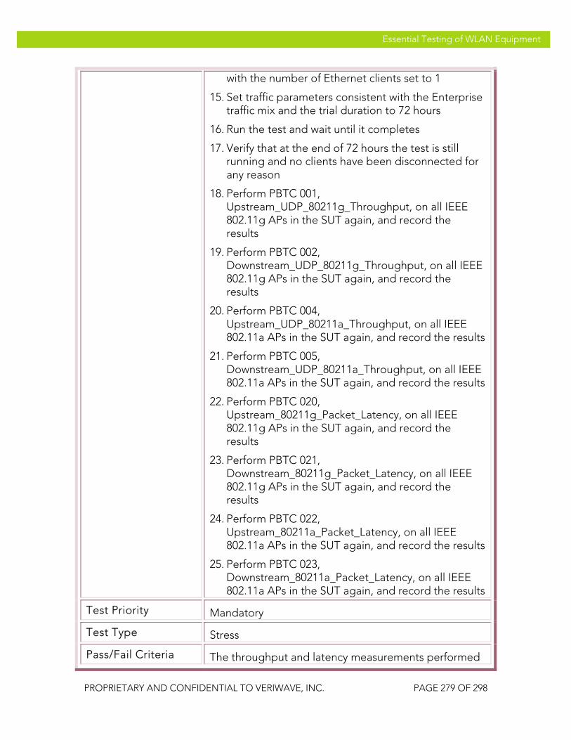
VeriWave, Inc. Essential Testing of WLAN Equipment
PROPRIETARY AND CONFIDENTIAL TO VERIWAVE, INC. PAGE 279 OF 298
Essential Testing of WLAN Equipment
with the number of Ethernet clients set to 1
15. Set traffic parameters consistent with the Enterprise traffic mix and the trial duration to 72 hours
16. Run the test and wait until it completes
17. Verify that at the end of 72 hours the test is still running and no clients have been disconnected for any reason
18. Perform PBTC 001, Upstream_UDP_80211g_Throughput, on all IEEE 802.11g APs in the SUT again, and record the results
19. Perform PBTC 002, Downstream_UDP_80211g_Throughput, on all IEEE 802.11g APs in the SUT again, and record the results
20. Perform PBTC 004, Upstream_UDP_80211a_Throughput, on all IEEE 802.11a APs in the SUT again, and record the results
21. Perform PBTC 005, Downstream_UDP_80211a_Throughput, on all IEEE 802.11a APs in the SUT again, and record the results
22. Perform PBTC 020, Upstream_80211g_Packet_Latency, on all IEEE 802.11g APs in the SUT again, and record the results
23. Perform PBTC 021, Downstream_80211g_Packet_Latency, on all IEEE 802.11g APs in the SUT again, and record the results
24. Perform PBTC 022, Upstream_80211a_Packet_Latency, on all IEEE 802.11a APs in the SUT again, and record the results
25. Perform PBTC 023, Downstream_80211a_Packet_Latency, on all IEEE 802.11a APs in the SUT again, and record the results
Test Priority Mandatory
Test Type Stress
Pass/Fail Criteria The throughput and latency measurements performed
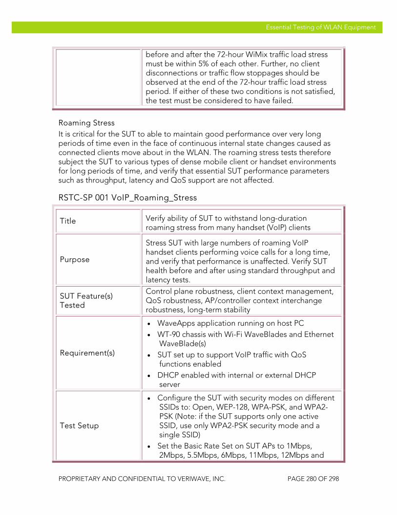
VeriWave, Inc. Essential Testing of WLAN Equipment
PROPRIETARY AND CONFIDENTIAL TO VERIWAVE, INC. PAGE 280 OF 298
Essential Testing of WLAN Equipment
before and after the 72-hour WiMix traffic load stress must be within 5% of each other. Further, no client disconnections or traffic flow stoppages should be observed at the end of the 72-hour traffic load stress period. If either of these two conditions is not satisfied, the test must be considered to have failed.
Roaming Stress It is critical for the SUT to able to maintain good performance over very long periods of time even in the face of continuous internal state changes caused as connected clients move about in the WLAN. The roaming stress tests therefore subject the SUT to various types of dense mobile client or handset environments for long periods of time, and verify that essential SUT performance parameters such as throughput, latency and QoS support are not affected.
RSTC-SP 001 VoIP_Roaming_Stress
Title Verify ability of SUT to withstand long-duration roaming stress from many handset (VoIP) clients
Purpose
Stress SUT with large numbers of roaming VoIP handset clients performing voice calls for a long time, and verify that performance is unaffected. Verify SUT health before and after using standard throughput and latency tests.
SUT Feature(s) Tested
Control plane robustness, client context management, QoS robustness, AP/controller context interchange robustness, long-term stability
Requirement(s)
• WaveApps application running on host PC • WT-90 chassis with Wi-Fi WaveBlades and Ethernet
WaveBlade(s) • SUT set up to support VoIP traffic with QoS
functions enabled • DHCP enabled with internal or external DHCP
server
Test Setup
• Configure the SUT with security modes on different SSIDs to: Open, WEP-128, WPA-PSK, and WPA2-PSK (Note: if the SUT supports only one active SSID, use only WPA2-PSK security mode and a single SSID)
• Set the Basic Rate Set on SUT APs to 1Mbps, 2Mbps, 5.5Mbps, 6Mbps, 11Mbps, 12Mbps and

VeriWave, Inc. Essential Testing of WLAN Equipment
PROPRIETARY AND CONFIDENTIAL TO VERIWAVE, INC. PAGE 281 OF 298
Essential Testing of WLAN Equipment
24Mbps (IEEE 802.11g APs) and/or 6Mbps, 12Mbps and 24Mbps (IEEE 802.11a APs, if applicable)
• Set the handset codec to G.711 and the baseline call duration to 5 minutes
• Set handset security types to match those in the SUT
• Run test with 500 roaming handsets total
Procedure
1. Configure the SUT as indicated above
2. Perform PBTC 001, Upstream_UDP_80211g_Throughput, on all IEEE 802.11g APs in the SUT as a group, and record the results
3. Perform PBTC 002, Downstream_UDP_80211g_Throughput, on all IEEE 802.11g APs in the SUT as a group, and record the results
4. Perform PBTC 004, Upstream_UDP_80211a_Throughput, on all IEEE 802.11a APs in the SUT as a group, and record the results
5. Perform PBTC 005, Downstream_UDP_80211a_Throughput, on all IEEE 802.11a APs in the SUT as a group, and record the results
6. Perform PBTC 020, Upstream_80211g_Packet_Latency, on all IEEE 802.11g APs in the SUT as a group, and record the results
7. Perform PBTC 021, Downstream_80211g_Packet_Latency, on all IEEE 802.11g APs in the SUT as a group, and record the results
8. Perform PBTC 022, Upstream_80211a_Packet_Latency, on all IEEE 802.11a APs in the SUT as a group, and record the results
9. Perform PBTC 023, Downstream_80211a_Packet_Latency, on all IEEE 802.11a APs in the SUT as a group, and record the results

VeriWave, Inc. Essential Testing of WLAN Equipment
PROPRIETARY AND CONFIDENTIAL TO VERIWAVE, INC. PAGE 282 OF 298
Essential Testing of WLAN Equipment
10. Launch the WaveApps application
11. Select the Roaming Service Quality test
12. Select the test ports (i.e., APs) to use for the Roaming Service Quality test and configure each port into IEEE 802.11g or IEEE 802.11a mode as required
13. Create client groups to support 500 roaming handsets; select the SSIDs for the handsets and configure them to the appropriate security modes for the SSIDs; assign IP addresses using DHCP
14. Create an Ethernet client group on the correct ports with the number of Ethernet clients set to 1
15. Place all handsets into the roam sequence
16. Set the roam rate to 30 roams/minute and set the total roaming duration to 72 hours
17. Set the codec type to G.711 and the baseline call duration to 5 minutes
18. Run the test and wait until it completes
19. Verify that at the end of 72 hours clients are continuing to roam
20. Perform PBTC 001, Upstream_UDP_80211g_Throughput, on all IEEE 802.11g APs in the SUT as a group again, and record the results
21. Perform PBTC 002, Downstream_UDP_80211g_Throughput, on all IEEE 802.11g APs in the SUT as a group again, and record the results
22. Perform PBTC 004, Upstream_UDP_80211a_Throughput, on all IEEE 802.11a APs in the SUT as a group again, and record the results
23. Perform PBTC 005, Downstream_UDP_80211a_Throughput, on all IEEE 802.11a APs in the SUT as a group again, and record the results
24. Perform PBTC 020, Upstream_80211g_Packet_Latency, on all IEEE
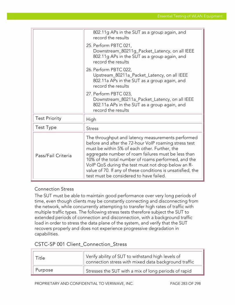
VeriWave, Inc. Essential Testing of WLAN Equipment
PROPRIETARY AND CONFIDENTIAL TO VERIWAVE, INC. PAGE 283 OF 298
Essential Testing of WLAN Equipment
802.11g APs in the SUT as a group again, and record the results
25. Perform PBTC 021, Downstream_80211g_Packet_Latency, on all IEEE 802.11g APs in the SUT as a group again, and record the results
26. Perform PBTC 022, Upstream_80211a_Packet_Latency, on all IEEE 802.11a APs in the SUT as a group again, and record the results
27. Perform PBTC 023, Downstream_80211a_Packet_Latency, on all IEEE 802.11a APs in the SUT as a group again, and record the results
Test Priority High
Test Type Stress
Pass/Fail Criteria
The throughput and latency measurements performed before and after the 72-hour VoIP roaming stress test must be within 5% of each other. Further, the aggregate number of roam failures must be less than 10% of the total number of roams performed, and the VoIP QoS during the test must not drop below an R-value of 70. If any of these conditions is unsatisfied, the test must be considered to have failed.
Connection Stress The SUT must be able to maintain good performance over very long periods of time, even though clients may be constantly connecting and disconnecting from the network, while concurrently attempting to transfer high rates of traffic with multiple traffic types. The following stress tests therefore subject the SUT to extended periods of connection and disconnection, with a background traffic load in order to stress the data plane of the system, and verify that the SUT recovers properly and does not experience progressive degradation in capabilities.
CSTC-SP 001 Client_Connection_Stress
Title Verify ability of SUT to withstand high levels of connection stress with mixed data background traffic
Purpose Stresses the SUT with a mix of long periods of rapid

VeriWave, Inc. Essential Testing of WLAN Equipment
PROPRIETARY AND CONFIDENTIAL TO VERIWAVE, INC. PAGE 284 OF 298
Essential Testing of WLAN Equipment
connections and disconnections (AAA Authentication Load Test) plus high data traffic load of multiple traffic types (WiMix Test). SUT data plane and control plane performance is verified before and after the test period using standard throughput, latency, and client capacity measurements.
SUT Feature(s) Tested
Control path robustness, client context management, control path and data path interaction, long-term stability
Requirement(s)
• One instance of WaveApps and two instances of WaveVCE running on one or more host PCs
• WT-90 chassis with Wi-Fi WaveBlades and Ethernet WaveBlades
• SUT set up to support multiple SSIDs • DHCP enabled with internal or external DHCP
server
Test Setup
• Configure the SUT with security modes on different SSIDs to: Open, WEP-128, WPA-PSK, and WPA2-PSK (Note: if the SUT supports only one active SSID, use only WPA2-PSK security mode and a single SSID)
• Set Basic Rate Set on SUT APs to 1Mbps, 2Mbps, 5.5Mbps, 6Mbps, 11Mbps, 12Mbps and 24Mbps (IEEE 802.11g APs) and/or 6Mbps, 12Mbps and 24Mbps (IEEE 802.11a APs, if applicable)
• Set client PHY rate to 54 Mb/s • Set client security types to match those in the SUT • Set client authentication load to 10 connections per
second • Set number of clients to 50 WiMix clients per AP, or
100 Authentication Load Test clients per AP
Procedure
1. Configure the SUT as indicated above
2. Perform PBTC 001, Upstream_UDP_80211g_Throughput, on all IEEE 802.11g APs in the SUT, and record the results
3. Perform PBTC 002, Downstream_UDP_80211g_Throughput, on all IEEE 802.11g APs in the SUT, and record the results
4. Perform PBTC 004, Upstream_UDP_80211a_Throughput, on all IEEE

VeriWave, Inc. Essential Testing of WLAN Equipment
PROPRIETARY AND CONFIDENTIAL TO VERIWAVE, INC. PAGE 285 OF 298
Essential Testing of WLAN Equipment
802.11a APs in the SUT, and record the results
5. Perform PBTC 005, Downstream_UDP_80211a_Throughput, on all IEEE 802.11a APs in the SUT, and record the results
6. Perform PBTC 020, Upstream_80211g_Packet_Latency, on all IEEE 802.11g APs in the SUT, and record the results
7. Perform PBTC 021, Downstream_80211g_Packet_Latency, on all IEEE 802.11g APs in the SUT, and record the results
8. Perform PBTC 022, Upstream_80211a_Packet_Latency, on all IEEE 802.11a APs in the SUT, and record the results
9. Perform PBTC 023, Downstream_80211a_Packet_Latency, on all IEEE 802.11a APs in the SUT, and record the results
10. Perform CBTC 002, Max_Client_Capacity_DHCP, on all APs in the SUT and record the results
11. Launch the first instance of the WaveVCE application
12. Select the WiMix test and select the Enterprise profile within the WiMix test
13. Select the test ports (i.e., APs) to use for the WiMix test and configure each port into IEEE 802.11g or IEEE 802.11a mode as required; 50% of the SUT test ports should be selected to sustain WiMix traffic
14. Create client groups to support (50 x N) WiMix clients, where N is the number of APs in the SUT used for the WiMix test; select the SSIDs for the clients and configure the clients to the appropriate security modes for the SSIDs, and assign IP addresses using DHCP
15. Create an Ethernet client group on the correct ports with the number of Ethernet clients set to 1
16. Set traffic parameters consistent with the Enterprise traffic mix and the trial duration to 72 hours
17. Now launch the second instance of the WaveVCE application, on the same or a different host PC
18. Select the AAA Authentication Load test under the
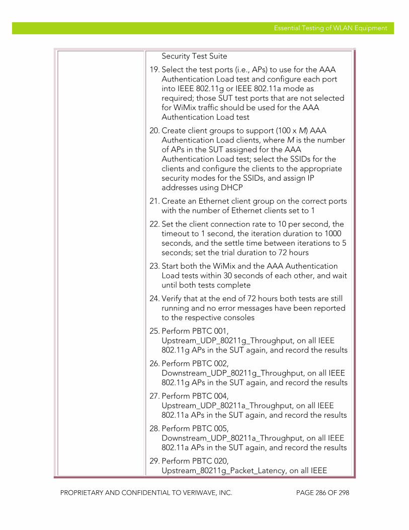
VeriWave, Inc. Essential Testing of WLAN Equipment
PROPRIETARY AND CONFIDENTIAL TO VERIWAVE, INC. PAGE 286 OF 298
Essential Testing of WLAN Equipment
Security Test Suite
19. Select the test ports (i.e., APs) to use for the AAA Authentication Load test and configure each port into IEEE 802.11g or IEEE 802.11a mode as required; those SUT test ports that are not selected for WiMix traffic should be used for the AAA Authentication Load test
20. Create client groups to support (100 x M) AAA Authentication Load clients, where M is the number of APs in the SUT assigned for the AAA Authentication Load test; select the SSIDs for the clients and configure the clients to the appropriate security modes for the SSIDs, and assign IP addresses using DHCP
21. Create an Ethernet client group on the correct ports with the number of Ethernet clients set to 1
22. Set the client connection rate to 10 per second, the timeout to 1 second, the iteration duration to 1000 seconds, and the settle time between iterations to 5 seconds; set the trial duration to 72 hours
23. Start both the WiMix and the AAA Authentication Load tests within 30 seconds of each other, and wait until both tests complete
24. Verify that at the end of 72 hours both tests are still running and no error messages have been reported to the respective consoles
25. Perform PBTC 001, Upstream_UDP_80211g_Throughput, on all IEEE 802.11g APs in the SUT again, and record the results
26. Perform PBTC 002, Downstream_UDP_80211g_Throughput, on all IEEE 802.11g APs in the SUT again, and record the results
27. Perform PBTC 004, Upstream_UDP_80211a_Throughput, on all IEEE 802.11a APs in the SUT again, and record the results
28. Perform PBTC 005, Downstream_UDP_80211a_Throughput, on all IEEE 802.11a APs in the SUT again, and record the results
29. Perform PBTC 020, Upstream_80211g_Packet_Latency, on all IEEE

VeriWave, Inc. Essential Testing of WLAN Equipment
PROPRIETARY AND CONFIDENTIAL TO VERIWAVE, INC. PAGE 287 OF 298
Essential Testing of WLAN Equipment
802.11g APs in the SUT again, and record the results
30. Perform PBTC 021, Downstream_80211g_Packet_Latency, on all IEEE 802.11g APs in the SUT again, and record the results
31. Perform PBTC 022, Upstream_80211a_Packet_Latency, on all IEEE 802.11a APs in the SUT again, and record the results
32. Perform PBTC 023, Downstream_80211a_Packet_Latency, on all IEEE 802.11a APs in the SUT again, and record the results
33. Perform CBTC 002, Max_Client_Capacity_DHCP, on all APs in the SUT and record the results
Test Priority Mandatory
Test Type System
Pass/Fail Criteria
The throughput and latency measurements performed before and after the 72-hour stress test must be within 5% of each other. Further, the client capacity measurements before and after the stress test must be equal. If either of these two conditions is not satisfied, the test must be considered to have failed.
CSTC-SP 002 Client_Connection_Data_Overload_Stress
Title Verify ability of SUT to withstand high levels of connection stress in the presence of UDP data traffic overloads
Purpose
Stresses the SUT with a mix of rapid connections and disconnections (AAA Authentication Rate Test) plus a steady-state downstream UDP data overload (packet loss test with ILOAD higher than theoretical maximum). SUT data plane performance is verified before and after the test period using standard throughput and latency measurements.
SUT Feature(s) Tested
Control path robustness, client context management, control stability under data overload, long-term stability
Requirement(s) • One instance of WaveApps and one instance of
WaveVCE running on one or more host PCs • WT-90 chassis string with Wi-Fi WaveBlades and at

VeriWave, Inc. Essential Testing of WLAN Equipment
PROPRIETARY AND CONFIDENTIAL TO VERIWAVE, INC. PAGE 288 OF 298
Essential Testing of WLAN Equipment
least 3 Ethernet WaveBlades • SUT with at least 10 APs set up to support multiple
SSIDs • DHCP enabled with internal or external DHCP
server
Test Setup
• Configure the SUT with security modes on different SSIDs to: Open, WEP-128, WPA-PSK, and WPA2-PSK (Note: if the SUT supports only one active SSID, use only WPA2-PSK security mode and a single SSID)
• Set Basic Rate Set on SUT APs to 1Mbps, 2Mbps, 5.5Mbps, 6Mbps, 11Mbps, 12Mbps and 24Mbps (IEEE 802.11g APs) and/or 6Mbps, 12Mbps and 24Mbps (IEEE 802.11a APs, if applicable)
• Set client PHY rate to 54 Mb/s • Set client security types to match those in the SUT • Set client authentication load to 20 connections per
second • Set the downstream UDP intended load applied per
Ethernet port to 512 byte packets and 100% of the theoretical maximum rate
• Set number of clients to 50 Packet Loss Test clients per AP, or 100 Authentication Load Test clients per AP
Procedure
1. Configure the SUT as indicated above
2. Perform PBTC 001, Upstream_UDP_80211g_Throughput, on all IEEE 802.11g APs in the SUT, and record the results
3. Perform PBTC 002, Downstream_UDP_80211g_Throughput, on all IEEE 802.11g APs in the SUT, and record the results
4. Perform PBTC 004, Upstream_UDP_80211a_Throughput, on all IEEE 802.11a APs in the SUT, and record the results
5. Perform PBTC 005, Downstream_UDP_80211a_Throughput, on all IEEE 802.11a APs in the SUT, and record the results
6. Perform PBTC 020, Upstream_80211g_Packet_Latency, on all IEEE 802.11g APs in the SUT, and record the results

VeriWave, Inc. Essential Testing of WLAN Equipment
PROPRIETARY AND CONFIDENTIAL TO VERIWAVE, INC. PAGE 289 OF 298
Essential Testing of WLAN Equipment
7. Perform PBTC 021, Downstream_80211g_Packet_Latency, on all IEEE 802.11g APs in the SUT, and record the results
8. Perform PBTC 022, Upstream_80211a_Packet_Latency, on all IEEE 802.11a APs in the SUT, and record the results
9. Perform PBTC 023, Downstream_80211a_Packet_Latency, on all IEEE 802.11a APs in the SUT, and record the results
10. Launch the WaveApps application
11. Select the Packet Loss Test under the IEEE 802.11.2 Benchmark Test Suite
12. Select the test ports (i.e., APs) to use for the UDP data traffic overload (i.e., the Packet Loss Test) and configure each port into IEEE 802.11g or IEEE 802.11a mode as required; 50% of the SUT Wi-Fi test ports should be selected to sustain the data traffic
13. Create client groups to support (50 x N) Packet Loss Test clients, where N is the number of APs in the SUT selected in step 12 above; select the SSIDs for the clients and configure the clients to the appropriate security modes for the SSIDs, and assign IP addresses using DHCP
14. Create Ethernet client group(s) on the correct Ethernet test ports with the total number of Ethernet clients set equal to the number of Wi-Fi clients; select all but one of the Ethernet WaveBlades to support these Ethernet clients
15. Select UDP traffic type, set the frame size to 512 bytes, and set the ILOAD to (235,000 * E) frames/second, where E is the number of Ethernet ports assigned for the Packet Loss Test
16. Set the trial duration to 72 hours
17. Now launch the WaveVCE application, on the same or a different host PC
18. Select the AAA Authentication Load test under the Security Test Suite
19. Select the test ports (i.e., APs) to use for the AAA

VeriWave, Inc. Essential Testing of WLAN Equipment
PROPRIETARY AND CONFIDENTIAL TO VERIWAVE, INC. PAGE 290 OF 298
Essential Testing of WLAN Equipment
Authentication Load test and configure each port into IEEE 802.11g or IEEE 802.11a mode as required; those SUT test ports that are not selected for WiMix traffic should be used for the AAA Authentication Load test
20. Create client groups to support (100 x M) AAA Authentication Load clients, where M is the number of APs in the SUT assigned for the AAA Authentication Load test; select the SSIDs for the clients and configure the clients to the appropriate security modes for the SSIDs, and assign IP addresses using DHCP
21. Create an Ethernet client group on the correct ports with the number of Ethernet clients set to 1
22. Set the client connection rate to 20 per second, the timeout to 1 second, the iteration duration to 1000 seconds, and the settle time between iterations to 5 seconds; set the trial duration to 72 hours
23. Start both the Packet Loss and AAA Authentication Load tests within 30 seconds of each other, and wait until both tests complete
24. Verify that at the end of 72 hours both tests are still running, no error messages have been reported to the respective consoles, and all of the clients in the Packet Loss test are still connected
25. Perform PBTC 001, Upstream_UDP_80211g_Throughput, on all IEEE 802.11g APs in the SUT again, and record the results
26. Perform PBTC 002, Downstream_UDP_80211g_Throughput, on all IEEE 802.11g APs in the SUT again, and record the results
27. Perform PBTC 004, Upstream_UDP_80211a_Throughput, on all IEEE 802.11a APs in the SUT again, and record the results
28. Perform PBTC 005, Downstream_UDP_80211a_Throughput, on all IEEE 802.11a APs in the SUT again, and record the results
29. Perform PBTC 020,

VeriWave, Inc. Essential Testing of WLAN Equipment
PROPRIETARY AND CONFIDENTIAL TO VERIWAVE, INC. PAGE 291 OF 298
Essential Testing of WLAN Equipment
Upstream_80211g_Packet_Latency, on all IEEE 802.11g APs in the SUT again, and record the results
30. Perform PBTC 021, Downstream_80211g_Packet_Latency, on all IEEE 802.11g APs in the SUT again, and record the results
31. Perform PBTC 022, Upstream_80211a_Packet_Latency, on all IEEE 802.11a APs in the SUT again, and record the results
32. Perform PBTC 023, Downstream_80211a_Packet_Latency, on all IEEE 802.11a APs in the SUT again, and record the results
Test Priority High
Test Type System
Pass/Fail Criteria
The throughput and latency measurements performed before and after the 72-hour stress test must be within 5% of each other. Otherwise, the test must be considered to have failed.
Overload Recovery The SUT must be able to withstand temporary overloads (in terms of both data and client connections) and recover after the overload is removed to the original state. Failure to recover to the original state indicates issues such as memory leaks or internal data corruption.
ORTC-SP 001 Data_Overload_Recovery
Title Verify ability of SUT to recover from a high degree of data traffic overload without adverse effects
Purpose
Determine whether the SUT can return to its original capabilities after a predetermined time period during which it is subjected to a high degree of data overload. A UDP packet loss test is used to provide the data traffic overload, and the measurement of SUT capabilities before and after is done using throughput, latency and VoIP roaming tests.
SUT Feature(s) Tested
Data path robustness, stability under data overload, recovery from overload

VeriWave, Inc. Essential Testing of WLAN Equipment
PROPRIETARY AND CONFIDENTIAL TO VERIWAVE, INC. PAGE 292 OF 298
Essential Testing of WLAN Equipment
Requirement(s)
• WaveApps running on a host PC • WT-90 chassis string with at least 25 Wi-Fi
WaveBlades and at least 5 Ethernet WaveBlades • SUT with at least 25 APs set up to support multiple
SSIDs • DHCP enabled with internal or external DHCP
server
Test Setup
• Configure the SUT with security modes on different SSIDs to: Open, WEP-128, WPA-PSK, and WPA2-PSK (Note: if the SUT supports only one active SSID, use only WPA2-PSK security mode and a single SSID)
• Set Basic Rate Set on SUT APs to 1Mbps, 2Mbps, 5.5Mbps, 6Mbps, 11Mbps, 12Mbps and 24Mbps (IEEE 802.11g APs) and/or 6Mbps, 12Mbps and 24Mbps (IEEE 802.11a APs, if applicable)
• Set client PHY rate to 54 Mb/s • Set client security types to match those in the SUT • Set the downstream UDP intended load applied per
Ethernet port to 512 byte packets and 100% of the theoretical maximum rate
• Set the number of clients to 50 per AP
Procedure
1. Configure the SUT as indicated above
2. Perform PBTC 001, Upstream_UDP_80211g_Throughput, on all IEEE 802.11g APs in the SUT, and record the results
3. Perform PBTC 002, Downstream_UDP_80211g_Throughput, on all IEEE 802.11g APs in the SUT, and record the results
4. Perform PBTC 004, Upstream_UDP_80211a_Throughput, on all IEEE 802.11a APs in the SUT, and record the results
5. Perform PBTC 005, Downstream_UDP_80211a_Throughput, on all IEEE 802.11a APs in the SUT, and record the results
6. Perform PBTC 020, Upstream_80211g_Packet_Latency, on all IEEE 802.11g APs in the SUT, and record the results
7. Perform PBTC 021,

VeriWave, Inc. Essential Testing of WLAN Equipment
PROPRIETARY AND CONFIDENTIAL TO VERIWAVE, INC. PAGE 293 OF 298
Essential Testing of WLAN Equipment
Downstream_80211g_Packet_Latency, on all IEEE 802.11g APs in the SUT, and record the results
8. Perform PBTC 022, Upstream_80211a_Packet_Latency, on all IEEE 802.11a APs in the SUT, and record the results
9. Perform PBTC 023, Downstream_80211a_Packet_Latency, on all IEEE 802.11a APs in the SUT, and record the results
10. Perform PBTC 163, VoIP_Roaming_80211g, on all IEEE 802.11g APs in the SUT, and record the results
11. Perform PBTC 164, VoIP_Roaming_80211a, on all IEEE 802.11a APs in the SUT, and record the results
12. Wait 60 seconds after performing the above tests for the SUT to settle
13. Launch the WaveApps application
14. Select the Packet Loss Test under the IEEE 802.11.2 Benchmark Test Suite
15. Select the test ports (i.e., APs) to use for the UDP data traffic overload (i.e., the Packet Loss Test) and configure each port into IEEE 802.11g or IEEE 802.11a mode as required
16. Create client groups to support (50 x N) Packet Loss Test clients, where N is the number of APs in the SUT used in the test; select the SSIDs for the clients and configure the clients to the appropriate security modes for the SSIDs, and assign IP addresses using DHCP
17. Create Ethernet client group(s) on the correct Ethernet test ports with the total number of Ethernet clients set equal to the number of Wi-Fi clients
18. Select UDP traffic type, set the frame size to 512 bytes, and set the ILOAD to (235,000 * E) frames/second, where E is the number of Ethernet ports used in the test
19. Set the trial duration to 72 hours
20. Run the Packet Loss Test and wait until it completes
21. Verify that at the end of 72 hours the test is still running, no error messages have been reported to

VeriWave, Inc. Essential Testing of WLAN Equipment
PROPRIETARY AND CONFIDENTIAL TO VERIWAVE, INC. PAGE 294 OF 298
Essential Testing of WLAN Equipment
the console, and all of the clients are still connected
22. Wait at least 300 seconds after the above test has completed to allow the SUT to settle and recover if necessary
23. Perform PBTC 001, Upstream_UDP_80211g_Throughput, on all IEEE 802.11g APs in the SUT again, and record the results
24. Perform PBTC 002, Downstream_UDP_80211g_Throughput, on all IEEE 802.11g APs in the SUT again, and record the results
25. Perform PBTC 004, Upstream_UDP_80211a_Throughput, on all IEEE 802.11a APs in the SUT again, and record the results
26. Perform PBTC 005, Downstream_UDP_80211a_Throughput, on all IEEE 802.11a APs in the SUT again, and record the results
27. Perform PBTC 020, Upstream_80211g_Packet_Latency, on all IEEE 802.11g APs in the SUT again, and record the results
28. Perform PBTC 021, Downstream_80211g_Packet_Latency, on all IEEE 802.11g APs in the SUT again, and record the results
29. Perform PBTC 022, Upstream_80211a_Packet_Latency, on all IEEE 802.11a APs in the SUT again, and record the results
30. Perform PBTC 023, Downstream_80211a_Packet_Latency, on all IEEE 802.11a APs in the SUT again, and record the results
31. Perform PBTC 163, VoIP_Roaming_80211g, on all IEEE 802.11g APs in the SUT, and record the results
32. Perform PBTC 164, VoIP_Roaming_80211a, on all IEEE 802.11a APs in the SUT, and record the results
Test Priority Mandatory
Test Type System
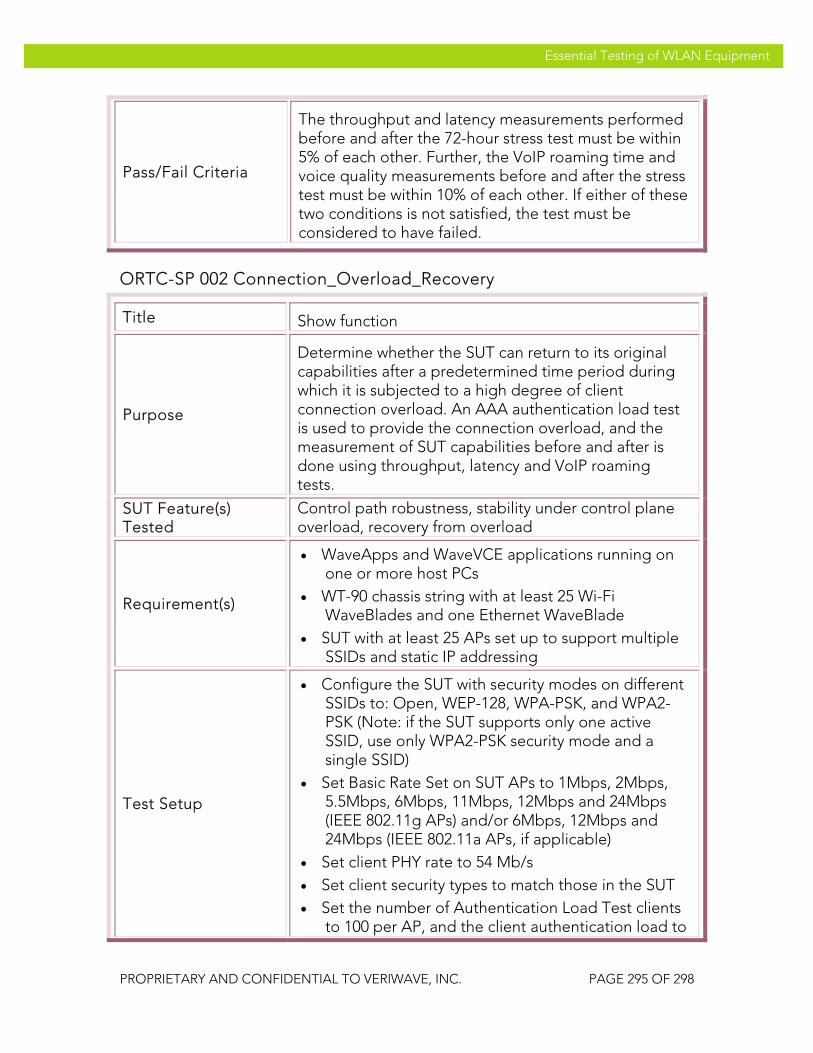
VeriWave, Inc. Essential Testing of WLAN Equipment
PROPRIETARY AND CONFIDENTIAL TO VERIWAVE, INC. PAGE 295 OF 298
Essential Testing of WLAN Equipment
Pass/Fail Criteria
The throughput and latency measurements performed before and after the 72-hour stress test must be within 5% of each other. Further, the VoIP roaming time and voice quality measurements before and after the stress test must be within 10% of each other. If either of these two conditions is not satisfied, the test must be considered to have failed.
ORTC-SP 002 Connection_Overload_Recovery
Title Show function
Purpose
Determine whether the SUT can return to its original capabilities after a predetermined time period during which it is subjected to a high degree of client connection overload. An AAA authentication load test is used to provide the connection overload, and the measurement of SUT capabilities before and after is done using throughput, latency and VoIP roaming tests.
SUT Feature(s) Tested
Control path robustness, stability under control plane overload, recovery from overload
Requirement(s)
• WaveApps and WaveVCE applications running on one or more host PCs
• WT-90 chassis string with at least 25 Wi-Fi WaveBlades and one Ethernet WaveBlade
• SUT with at least 25 APs set up to support multiple SSIDs and static IP addressing
Test Setup
• Configure the SUT with security modes on different SSIDs to: Open, WEP-128, WPA-PSK, and WPA2-PSK (Note: if the SUT supports only one active SSID, use only WPA2-PSK security mode and a single SSID)
• Set Basic Rate Set on SUT APs to 1Mbps, 2Mbps, 5.5Mbps, 6Mbps, 11Mbps, 12Mbps and 24Mbps (IEEE 802.11g APs) and/or 6Mbps, 12Mbps and 24Mbps (IEEE 802.11a APs, if applicable)
• Set client PHY rate to 54 Mb/s • Set client security types to match those in the SUT • Set the number of Authentication Load Test clients
to 100 per AP, and the client authentication load to

VeriWave, Inc. Essential Testing of WLAN Equipment
PROPRIETARY AND CONFIDENTIAL TO VERIWAVE, INC. PAGE 296 OF 298
Essential Testing of WLAN Equipment
30 connections per second
Procedure
1. Configure the SUT as indicated above
2. Perform PBTC 001, Upstream_UDP_80211g_Throughput, on all IEEE 802.11g APs in the SUT, and record the results
3. Perform PBTC 002, Downstream_UDP_80211g_Throughput, on all IEEE 802.11g APs in the SUT, and record the results
4. Perform PBTC 004, Upstream_UDP_80211a_Throughput, on all IEEE 802.11a APs in the SUT, and record the results
5. Perform PBTC 005, Downstream_UDP_80211a_Throughput, on all IEEE 802.11a APs in the SUT, and record the results
6. Perform PBTC 020, Upstream_80211g_Packet_Latency, on all IEEE 802.11g APs in the SUT, and record the results
7. Perform PBTC 021, Downstream_80211g_Packet_Latency, on all IEEE 802.11g APs in the SUT, and record the results
8. Perform PBTC 022, Upstream_80211a_Packet_Latency, on all IEEE 802.11a APs in the SUT, and record the results
9. Perform PBTC 023, Downstream_80211a_Packet_Latency, on all IEEE 802.11a APs in the SUT, and record the results
10. Perform PBTC 163, VoIP_Roaming_80211g, on all IEEE 802.11g APs in the SUT, and record the results
11. Perform PBTC 164, VoIP_Roaming_80211a, on all IEEE 802.11a APs in the SUT, and record the results
12. Wait 60 seconds after performing the above tests for the SUT to settle
13. Launch the WaveVCE application
14. Select the AAA Authentication Load test under the Security Test Suite
15. Select the test ports (i.e., APs) to use for the UDP data traffic overload (i.e., the Packet Loss Test) and configure each port into IEEE 802.11g or IEEE

VeriWave, Inc. Essential Testing of WLAN Equipment
PROPRIETARY AND CONFIDENTIAL TO VERIWAVE, INC. PAGE 297 OF 298
Essential Testing of WLAN Equipment
802.11a mode as required
16. Create client groups to support (100 x M) AAA Authentication Load clients, where M is the number of APs in the SUT assigned for the AAA Authentication Load test
17. Select the SSIDs for the test clients and configure the clients to the appropriate security modes for the SSIDs, and assign IP addresses statically
18. Create an Ethernet client group on the Ethernet test port with the number of Ethernet clients set to 1
19. Set the client connection rate to 30 per second, the timeout to 1 second, the iteration duration to 1000 seconds, and the settle time between iterations to 5 seconds
20. Set the trial duration to 72 hours
21. Run the AAA Authentication Load Test and wait until it completes
22. Verify that at the end of 72 hours that no error messages have been reported to the console
23. Wait at least 300 seconds after the above test has completed to allow the SUT to settle and recover if necessary
24. Perform PBTC 001, Upstream_UDP_80211g_Throughput, on all IEEE 802.11g APs in the SUT again, and record the results
25. Perform PBTC 002, Downstream_UDP_80211g_Throughput, on all IEEE 802.11g APs in the SUT again, and record the results
26. Perform PBTC 004, Upstream_UDP_80211a_Throughput, on all IEEE 802.11a APs in the SUT again, and record the results
27. Perform PBTC 005, Downstream_UDP_80211a_Throughput, on all IEEE 802.11a APs in the SUT again, and record the results
28. Perform PBTC 020, Upstream_80211g_Packet_Latency, on all IEEE 802.11g APs in the SUT again, and record the results
29. Perform PBTC 021, Downstream_80211g_Packet_Latency, on all IEEE

VeriWave, Inc. Essential Testing of WLAN Equipment
PROPRIETARY AND CONFIDENTIAL TO VERIWAVE, INC. PAGE 298 OF 298
Essential Testing of WLAN Equipment
802.11g APs in the SUT again, and record the results
30. Perform PBTC 022, Upstream_80211a_Packet_Latency, on all IEEE 802.11a APs in the SUT again, and record the results
31. Perform PBTC 023, Downstream_80211a_Packet_Latency, on all IEEE 802.11a APs in the SUT again, and record the results
32. Perform PBTC 163, VoIP_Roaming_80211g, on all IEEE 802.11g APs in the SUT, and record the results
33. Perform PBTC 164, VoIP_Roaming_80211a, on all IEEE 802.11a APs in the SUT, and record the results
Test Priority High
Test Type System
Pass/Fail Criteria
The throughput and latency measurements performed before and after the 72-hour stress test must be within 5% of each other. Further, the VoIP roaming time and voice quality measurements before and after the stress test must be within 10% of each other. If either of these two conditions is not satisfied, the test must be considered to have failed.