eso adaptive optics facility progress report · eso adaptive optics facility progress report ......
TRANSCRIPT
Updated 1 March 2012
ESO Adaptive Optics Facility Progress Report
Robin Arsenault*1, Pierre-Yves Madec, Jerome Paufique, Paolo La Penna, Stefan Stroebele, Elise Vernet, Jean-Francois Pirard, Wolfgang Hackenberg, Harald Kuntschner, Lieselotte Jochum, Johann
Kolb, Nicolas Muller, Miska Le Louarn, Paola Amico, Norbert Hubin, Jean-Louis Lizon, Rob Ridings, Jose A. Abad, Gert Fischer, Volker Heinz, Mario Kiekebusch, Javier Argomedo, Ralf
Conzelmann, Sebastien Tordo, Rob Donaldson, Christian Soenke, Philippe Duhoux, Enrico Fedrigo, Bernard Delabre, Andrea Jost, Michel Duchateau, Mark Downing, Javier R. Moreno, Reinhold
Dorn, Antonio Manescau, Domenico Bonaccini Calia, Marco Quattri, Christophe Dupuy, Ivan M. Guidolin, Mauro Comin, Ronald Guzman, Bernard Buzzoni, Jutta Quentin, Steffan Lewis, Paul
Jolley, Max Kraus, Thomas Pfrommer, European Southern Observatory, Karl-Schwarzshild-Str.2, 85748 Garching bei Muenchen, Germany
Roberto Biasia, Daniele Gallienib, Clementine Bechetc, Remko Stuikd, , aMicrogate, Via Stradivari, 4, I-39100 - BOLZANO-BOZEN, Italy; bA.D.S. International S.r.l., via
Roma, 87, 23868 Valmadrera (Lc), ITALY; cCentre de Recherches Astronomiques de Lyon, Observatoire de Lyon, 9, Avenue Charles André, 69230 Saint Genis-Laval, France; dLeiden
Observatory, P.O. Box 9513, NL-2300 RA Leiden, The Netherlands
ABSTRACT
The ESO Adaptive Optics Facility (AOF) consists in an evolution of one of the ESO VLT unit telescopes to a laser driven adaptive telescope with a deformable mirror in its optical train.
The project has completed the procurement phase and several large structures have been delivered to Garching (Germany) and are being integrated (the AO modules GRAAL and GALACSI and the ASSIST test bench). The 4LGSF Laser (TOPTICA) has undergone final design review and a pre-production unit has been built and successfully tested. The Deformable Secondary Mirror is fully integrated and system tests have started with the first science grade thin shell mirror delivered by SAGEM. The integrated modules will be tested in stand-alone mode in 2012 and upon delivery of the DSM in late 2012, the system test phase will start. A commissioning strategy has been developed and will be updated before delivery to Paranal. A substantial effort has been spent in 2011-2012 to prepare the unit telescope to receive the AOF by preparing the mechanical interfaces and upgrading the cooling and electrical network. This preparation will also simplify the final installation of the facility on the telescope.
A lot of attention is given to the system calibration, how to record and correct any misalignment and control the whole facility. A plan is being developed to efficiently operate the AOF after commissioning. This includes monitoring a relevant set of atmospheric parameters for scheduling and a Laser Traffic control system to assist the operator during the night and help/support the observing block preparation.
Keywords: Adaptive facility, Ground layer correction, Laser tomography, adaptive secondary, on-sky calibration
1. INTRODUCTION The Adaptive Optics Facility project consists in transforming the fourth unit telescope of the VLT into an adaptive telescope. To this purpose a new M2-Unit is implemented with a deformable mirror hosting 1170 voice coil actuators. Four 20 W sodium laser guide stars are being launched from the telescope centerpiece to provide the guide sources for the adaptive optics modules GRAAL, feeding the large IR field of view imager Hawk-I and GALACSI, feeding the integral field spectrograph MUSE. The two AO modules provide a Ground Layer Adaptive Optics correction while GALACSI also provides MUSE with a Laser Tomography mode delivering a 5 to 10% strehl ratio in the visible. The
1 [email protected] ; phone: +49 89 3200 6524; fax: +49 89 320 2362; www.eso.org

Updated 1 March 2012
project started phase B in 2006 and is now well into integration. The system test phase will start imminently with the full fledged ASSIST test bench allowing full closed loop tests of the AOF modules with the DSM. The first activities to prepare the unit telescope#4 (UT4) to receive the AOF have taken place in last April and were successful.
The facility has been described previously in various papers; see [1], [2], [3].
Several papers relating to the AOF are being presented in the scope of the present conference; see references [4] to [18].
2. PROJECT MAIN MILESTONES 2.1 Project Status Overview
The AOF project has completed all phase C reviews in the course of 2010. Most main procurements have also been completed and the integration phase has started in ESO headquarter (Germany). At the time of this writing the Garching Integration hall contains the GRAAL and GALACSI adaptive optics modules, each on a test stand and the ASSIST test bench. Both AO modules are almost completely integrated with optics, motion stages and electronics all controlled from a preliminary version of the control software.
ASSIST test bench optical alignment is nearly completed with an integration configuration.
A clean tent is installed and in standby awaiting the delivery of the DSM for late 2012; it will allow the delicate thin shell installation/removal procedures to be executed in a proper environment.
The DSM project is completing its system test this summer. A slumped borosilicate shell with magnets glued on it has been used for preliminary system tests. SAGEM has delivered successfully a first science grade thin shell mirror this January to the DSM contractors Microgate and ADS Intl. [16] which constitutes an important milestone and success for the AOF project. SESO has delivered the reference body, another complex optical piece, to ADS/Microgate in August 2010.
The 4LGSF facility is being integrated in a specific separate laboratory offering a thermal chamber to test sub-systems in the operational temperature range. Important sub-systems have been outsourced and are either commissioned or in an advanced stage of completion. For instance the Optical Tube Assembly (four units; part of launch telescope) have been delivered and the sodium 20 watt laser pre-production unit has undergone full system tests and complies with all main specifications [17]. The Optical Tube Assemblies have been designed and manufactured by TNO (the Netherlands) while the Laser has been contracted to TOPTICA (Germany) who is collaborating with MPB (Canada).
An important intervention on the existing telescope unit 4 of the VLT took place in March-April 2012 in order to prepare the telescope to receive the AOF. The operation has been a success and inaugurated the start of AOF activities in Paranal.
The ESO detector department has delivered a first 0 Read-Out Noise WaveFront Sensor camera to the SPHERE project (ESO Planet Finder) and a second identical unit has been delivered to the AOF project and is under test. All performance expectations have been validated by the first unit (see [18], [19]).
2.2 Optics delivery for the DSM
A major milestone of 2012 is the delivery of the first science grade thin shell by SAGEM. This is the first such thin shell produced in Europe and SAGEM has mastered and validated a full manufacturing process [16]. The shell optical face was tested before thinning and the testing for the concave face consisted in ensuring a constant shell thickness (constant after removal of the systematic difference due to the convex asphere). It was delivered to ADS in January 2012 and there immediately taken out of the transport container with the various handling tools (validated on dummy slumped shells) to start the process of back face coating and gluing of the magnets. These operations are now completed. The shell convex shape (optical surface) has a somewhat large WFE of 3.4 μm PV but within specification; indeed it can easily be corrected by the 1170 actuators of the DSM.
A simulation applied on the measured convex shape predicts that 6.6 nm RMS surface can be reached (7.5 nm RMS specified) by correcting ~855 modes. In such configuration a peak force of 0.12 N is applied on some actuators (10% of full stroke or 0.1N specified). Note that a 10nm RMS surface error can be reached by correcting a mere 300 modes which much less force on actuators (< 0.03N).

Updated 1 March 2012
Figure 1: The first science grade thin shell manufactured and delivered by SAGEM. On the left, the shell (convex) surface error at rest. On the right one sees the shell being handled by suction cups on a wiffle tree at ADS (Italy).
Figure 2: Left, the surface error RMS in meter (semi-log scale) versus the number of modes corrected. Right, the maximum force required (in Newton) versus the number of modes corrected, to bring the shell to the surface quality shown on the left hand figure. Note that the maximum force delivered by the actuators is 1 N.
Figure 3: The DSM reference body manufactured by SESO ((left). On the right-hand side the reference body after coating; one sees the metallic rings realizing the capacitance with the back coating on the shell for gap measurement.
0 200 400 600 800 1000 120010-9
10-8
10-7
10-6
0 200 400 600 800 1000 12000
0.02
0.04
0.06
0.08
0.1
0.12
0.14
0.16
Updated 1 March 2012
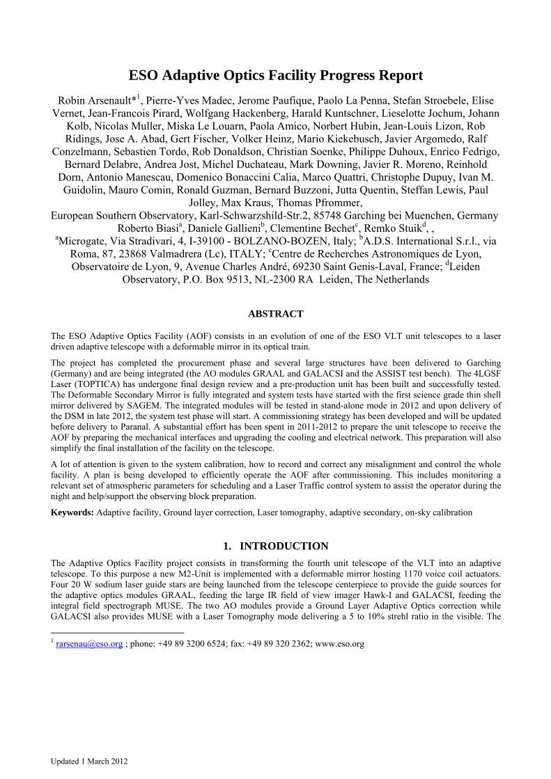
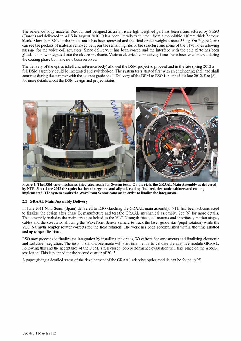
The reference body made of Zerodur and designed as an intricate lightweighted part has been manufactured by SESO (France) and delivered to ADS in August 2010. It has been literally “sculpted” from a monolithic 180mm thick Zerodur blank. More than 80% of the initial mass has been removed and the final optics weighs a mere 56 kg. On Figure 3 one can see the pockets of material removed between the remaining ribs of the structure and some of the 1170 holes allowing passage for the voice coil actuators. Since delivery, it has been coated and the interface with the cold plate has been glued. It is now integrated into the electro-mechanic. Various electrical connectivity issues have been encountered during the coating phase but have now been resolved.
The delivery of the optics (shell and reference body) allowed the DSM project to proceed and in the late spring 2012 a full DSM assembly could be integrated and switched-on. The system tests started first with an engineering shell and shall continue during the summer with the science grade shell. Delivery of the DSM to ESO is planned for late 2012. See [8] for more details about the DSM design and project status.
Figure 4: The DSM opto-mechanics integrated ready for System tests. On the right the GRAAL Main Assembly as delivered by NTE. Since June 2012 the optics has been integrated and aligned, cabling finalized, electronic cabinets and cooling implemented. The system awaits the WaveFront Sensor cameras in order to finalize the integration.
2.3 GRAAL Main Assembly Delivery
In June 2011 NTE Sener (Spain) delivered to ESO Garching the GRAAL main assembly. NTE had been subcontracted to finalize the design after phase B, manufacture and test the GRAAL mechanical assembly. See [6] for more details. This assembly includes the main structure bolted to the VLT Nasmyth focus, all mounts and interfaces, motion stages, cables and the co-rotator allowing the WaveFront Sensor camera to track the laser guide star (pupil rotation) while the VLT Nasmyth adaptor rotator corrects for the field rotation. The work has been accomplished within the time allotted and up to specifications.
ESO now proceeds to finalize the integration by installing the optics, Wavefront Sensor cameras and finalizing electronic and software integration. The tests in stand-alone mode will start imminently to validate the adaptive module GRAAL. Following this and the acceptance of the DSM, a full closed loop performance evaluation will take place on the ASSIST test bench. This is planned for the second quarter of 2013.
A paper giving a detailed status of the development of the GRAAL adaptive optics module can be found in [5].

Updated 1 March 2012
2.4 Integration of the Test Bench ASSIST
Figure 5: On the left the whole ASSIST test bench. One can see the temporary tower on top holding a flat mirror for optical alignment without the DSM mirror. ASSIST is completed by the Nasmyth adaptor/rotator test bench (white structure) which provides a mechanical interface to hold the Nasmyth adaptive modules GRAAL and GALACSI. The right hand picture shows the 1.7 m ASSIST main aspheric mirror manufactured by AMOS (Belgium).
The AOF test bench ASSIST is nearly completed. The main optics, the 1.7m aspheric mirror, has been successfully manufactured by AMOS, coated in Calar Alto facility and delivered to ESO headquarters in the summer 2011. The main mechanical structure underwent acceptance also in late summer 2011. The whole system was delivered and assembled in Garching headquarters in the fall 2011.
The main 1.7m mirror was specified to reach a certain optical quality per linear scales. Some linear scales requirements were relaxed where easily correctable by the DSM. This complex specification was successfully managed by AMOS. TNO manufactured the 140mm second mirror to proper specifications. In October 2011 the whole structure was assembled in ESO headquarters and later in 2012 the optical alignment was brought as close as possible to a final one without the DSM, which is part of the optical train. This was done by using a HASO64 (Imagine Optics, France) located at the center of curvature of the DSM. A strong residual spherical aberration is present but the setup allows validating ASSIST in stand-alone mode thanks to the large dynamic range of the HASO64.
The ASSIST test bench is described in more detail in [7] and section 3 describes the design and its role during the system test phase of the AOF. 2.5 The Sodium Fiber Laser pre-production unit
The AOF will use four 20 Watt fiber lasers to create artificial guide stars for the adaptive optics modules. TOPTICA (Germany) is the main contractor and collaborate with MPB (Canada) in charge of developing the infrared high power fiber laser. Given the technological challenges and the remaining development issues, it was requested from the contractor to manufacture a pre-production unit and comprehensively test it against the specifications before launching the serial units. This step has been reached and we are glad to report that the PPU Unit has now been assembled and tested. The PPU Unit test plan included the main optical and electrical parameters, and performance testing in representative environmental conditions (climate chamber tests under transient temperature conditions, reduced atmospheric pressure, mechanical flexures over gravity) during which key parameters of the laser were monitored. A number of these tests, such as EMC/EMI, shock and vibration were performed by a third party testing facility contracted by Toptica. Examples of some of the results are shown in Figure 6 and Figure 7.

Updated 1 March 2012
The power delivered by the laser amounts to 22.2 Watt distributed in 18 Watt in the main NaD2a line and 2.1 Watt in the NaD2b line (note that 2.1 Watts is also distributed in the counterpart of the NaD2b line, symmetrical in wavelength with respect to the D2a line). Stability is better than 2% PV over 18 hours.
Based on the PPU test results there are some areas where there is a need for optimization/ improvement and these have already been updated in the design documents and will be implemented in the serial unit production: these are minor aspects and include modification of the position of cable interface and improvement of the handling points, choice of seed laser diode, choice of servo-controller boards better adapted to the different seed laser diode.
Figure 6: Left, the laser head pre-production unit; with the insulation cover (not shown here) the full size is 900 mm x 700 mm x 385 mm and the assembly weighs 80 kg. Right: the laser output beam optical quality. The color scheme ranges from -0.1 to +0.1 lamba (@ 0.5 μm). The beam quality amounts to 23.3 nm RMS well below the specified 70 nm RMS, even below the goal set at 25 nm.
Figure 7: Output power stability over time (see text for explanation).

Updated 1 March 2012
2.6 The Preparation of the VLT Unit#4 Telescope
Early-on in the AOF project it was realized that the standard VLT unit and in particular unit telescope #4 would not be able to accommodate the AOF. The reason for that is that the telescope was designed to accommodate, from the point of view of electrical power, cooling power, network etc., 3 instruments. In the end, the unit#4 telescope will host 3 instruments and their corresponding 3 AO modules. Add to this the actual single Laser Guide Star Facility plus the new Four Laser Guide Star Facility and a full blown Deformable Secondary Mirror. Needless to say that several capacities of the VLT have been exceeded. This was clearly identified in the definition of the Interface Control Document between the AOF and the VLT. On the basis of the observed discrepancies a branch of the AOF project was dedicated to organize, procure and implement all the needed improvements. These include:
• Increased electrical power and cooling power distribution, as well as upgraded network of optical fibers;
• Pre-cabling of the 4LGSF laser and control electronics and of the DSM;
• “Cleaning” of the centerpiece to free the space for the installation of the 4LGSF;
• Extension of one Nasmyth platform and implementation of a sub-Nasmyth platform to offer more space for electrical cabinets;
• Implementation of mechanical interfaces on the telescope centerpiece to receive the 4LGSF electronic cabinets, laser cabinets and launch telescopes;
• Modifications to the Telescope Control Software to take into account the new status of adaptive telescope (see section 4) and implementation of a new Nasmyth Guider arm to extend the back focal length at Nasmyth (for GALACSI/MUSE);
• Design & implementation of a new maintenance platform for the DSM and definition of requirements for the assembly, integration and tests of AOF system at the Observatory (Paranal);
• Conversion of (part of) the telescope basement into a computer room for the installation of the computing capacity required for the AOF.
In February 2012 after several weeks of intensive manufacturing and procurement a set of 15 crates totaling 7 tons of material was shipped to Paranal providing part of the hardware required in view of the March 2012 intervention.
This intervention took place during a M1 mirror recoating operation, priority being given to the activities which endangered the M1 most; these were to be carried out while the mirror was out of the telescope structure. The intervention upgraded the cooling circuit to accommodate the additional needs for the 4LGSF and the DSM. An extensive scaffolding structure was erected inside the telescope struts, up to M2 and outside the centerpiece in order to give easy access to the telescope. This facilitated the removal of old cables/fibers/pipes and installation of new ones in the centerpiece and along the telescope struts. In the telescope basement new pumps were installed in order to feed the additional cooling circuits. Particular care was taken to ensure a proper insulation of the pumps and circuit to avoid propagation of vibrations into the telescope structure or onto the interferometer mirrors train.
There was also substantial mechanical work onto the centerpiece that required the above mentioned scaffolding. Several holes patterns had to be drilled in order to mount all the hardware required by the 4LGSF: right angle brackets for the 4LGSF and Laser electronics cabinets and for the launch telescope assemblies.
When completed the mounts were installed and dummy weights were bolted onto them. Finally, one altitude cable wrap was modified to accommodate a larger number of cables required by the AOF.
This strategy will make the future installation of the final 4LGSF hardware much simpler; dismounting dummy weights, remounting real cabinets and launch telescopes and connecting. The telescope will then be subjected to a minimum change in weight/moment. This reduces the telescope downtime to a minimum for the installation of this sub-system.
A test plan was defined to ensure that the behavior of the telescope was not degraded by the many modifications implemented. Particular attention was paid to tracking, fine guiding, field stabilization and servo-control of the telescope axis. A subset of the tests also concerned the vibrations measured through various structures in the dome including telescope mirrors. The tests were performed before and after the intervention. At the time of this writing the earlier performance of the telescope are confirmed and there are no indications of any negative outcome and or behavior.

Updated 1 March 2012
Figure 8: The unit telescope #4 being surrounded by scaffoldings to allow access to the centerpiece, serrurier struts and M2 spider. Note that the complete M1 cell has been removed during this operation. The red ellipse indicates all the brackets installed for mounting the 4LSGF electronic cabinets and the launch telescopes. Dummy weights are installed (see text for explanation).
3. ASSIST: THE AOF TEST BENCH The DSM and the two adaptive optics modules GALACSI Error! Reference source not found. and GRAAL Error! Reference source not found. will be fully tested in Europe before integration in the telescope using the ASSIST test-bed facility (see Error! Reference source not found. for a detailed description of ASSIST). Besides allowing the identification of potential problems, this will provide a full characterization of the systems, and speed up the on-sky calibration procedure, thus minimizing the commissioning time. The main testing configurations of ASSIST are sketched in Figure 9. In a first configuration (Figure 10, (a)), ASSIST will be used for DSM stand-alone testing and characterization. The light will be injected and collected by an interferometer (PhaseCam 4020). Controlled actuation will be exerted on the DSM actuators, in order to characterize the mirror and measure the influence functions. In this configuration only on-axis field position is required. In a second configuration (Figure 10, (b)) ASSIST reproduces the VLT f/#, angular field and pupil position. This will allow feeding GALACSI and GRAAL with the same wavefront they will get at the VLT Nasmyth. In order to keep the optics relatively small and affordable, the ASSIST field size has been limited to 2.5 arcmin to encompass the GALACSI WFM, with further implementation of a set of periscopes to provide the ASSIST sources to the correct location at the output focal plane for GRAAL. Visible and IR sources, NGS and LGS, are provided: each of the instrument modes uses 4 sodium Laser Guide Stars (Na-LGS) and a single Natural Guide Star (NGS) for tip-tilt and focus correction.

Updated 1 March 2012
Figure 9: Optical schematic of ASSIST with the DSM (on top of ASSIST): left (a): interferometer configuration; right (b): GRAAL/GALACSI configuration. AM1, AM2, FM1 are respectively the ASSIST primary, secondary and folding mirror. In (b): SSTG: Star Simulator and Turbulence Generator; VFS: VLT Focus Simulator; PS are the three phase screens (placed on the input pupil). Switching between the two configurations is performed by rotating the FM1 by 90° around the vertical.
ASSIST is providing NGS (infinite conjugated) visible sources for GALACSI wide filed mode tip-tilt and calibration, and for GRAAL tip-tilt, while for GRAAL calibration and for GALACSI narrow field mode it features IR natural guide source. Laser Guide Sources (100 km height conjugated) for both GALACSI and GRAAL are also provided. The optical design is optimized for 2 wavelengths: 589 nm for Na LGS and visible NGS, and 1.6 μm for the IR sources.
Figure 10: ASSIST with an adaptive optics module (in this case GALACSI) mounted on it for full AO characterization. “ITF” identifies the interferometer for DSM stand-alone testing. The light is injected by the “SSTG”, collected out through the “VFS” by the instrument, mounted on a full-scale telescope adapter. The instrument measures the wavefront, computes correction signals and performs feedback on the DSM. Turbulence is injected in the input wavefront by the rotating phase screens.

Updated 1 March 2012
Figure 10 shows a rendering of an adaptive module mounted on ASSIST and operating in closed loop with the DSM. In order to reproduce the expected behavior on the telescope, turbulence is injected in the input wavefront by three rotating phase screens (“PS” in Figure 9), manufactured by SILIOS (France), partially overlapping on the SSTG on the input pupil. The three screens are placed in positions conjugated at three different altitudes. Two of them are permanent (only position/altitude is changed), whereas a third one can be replaced to provide different global seeing conditions for GALACSI Wide Field Mode+GRAAL and GALACSI Narrow Field Mode. The speed of rotation can be adjusted to simulate different wind speed or coherence time of the turbulence. The phase screen parameters have been chosen in order to reproduce relevant global atmospheric conditions adapted to the different adaptive optics modules operating modes (see summary in Table 1).
Table 1: Phase screen parameters in the two main operating configurations: GALACSI+WFM and GRAAL, and GALACSI NFM (values at 500 nm wavelength). Using in total four phase screen plates, three of them in each configuration, it is possible to obtain the overall relevant atmospheric parameters listed in the two upper rows of the table. The outer scale parameter L0 is the same for all modes and set at 25 m.
GALACSI WFM + GRAAL GALACSI NFM
Overall atmospheric parameter
Seeing [“] r0 [m] τ0 [s] θ0 [“] Seeing [“] r0 [m] τ0 [s] θ0 [“]
1.1 0.094 2.8 1.65 0.65 0.16 2.8 2.6
Altitude [m]
ASSIST location
[mm]
Metapupil diameter
[mm] r0 [m] Cn
2×dH [m1/3]
Wind speed [ms-1]
Metapupil diameter
[mm] r0 [m] Cn
2×dH [m1/3]
Wind speed [ms-1]
0 0 20 0.123 4.9×10⁻¹³ 8 20 0.258 1.4×10⁻¹³ 10 5100 33.55 29 0.258 1.4×10⁻¹³ 16 22 0.258 1.4×10⁻¹³ 20 8000 50.95 35 0.258 1.4×10⁻¹³ 12 23 0.614 3.9×10⁻¹³ 32
ASSIST is at present integrated, aligned and ready for integration of the DSM at ESO in Garching (Germany). The first testing phase will involve the DSM alone in the ASSIST interferometric configuration. The main objectives of the optical tests of the DSM will be: • Optical calibration of the DSM capacitive sensors; • definition of the flat vector; • measurement of the influence functions; • actuators’ stroke characterization, including non-linearities and cross-couplings.
Once these tests are completed, GRAAL and GALACSI will be then mounted in succession for calibration and full performance tests. The objectives of these tests will be: • test of the interaction matrix calibration methods (no turbulence, static turbulence, time-evolving turbulence,
numerically simulated); • loop closure and AO performance characterization; gain in encircled energy and fwhm. Strehl ratio, closed loop
bandwidth; • chopping; • field stabilization; • focusing; • LGS and Visible/IR NGS acquisition and full AO performance optimization; • characterization of different correction algorithms and possible strategies for new methods; • off-line processes and data reduction optimization.

Updated 1 March 2012
4. AOF CONTROL STRATEGY One of the main challenges of the AOF is related to its interaction with the control of the telescope. The VLT unit telescopes are based on active optics where the shape of the primary mirror (M1) is controlled in real time to compensate for slowly evolving thermo-mechanical flexures. Every 30 to 60 seconds the commands sent to M1 are elaborated from the wavefront sensor measurements delivered by a Shack-Hartmann located in the guider arm of the telescope. This set of commands is defined in a modal basis made of the first elastic modes of M1; amongst them the tip-tilt, the defocus and the coma are sent to the positioning system of the secondary mirror (M2) while the other modes are driving M1. M2 tip-tilt is eventually offloaded to the altitude axis and the azimuth axis of the telescope.
When using a deformable secondary mirror (DSM) in adaptive optics mode the situation changes. Adaptive optics commands are elaborated from the wavefront sensors located in the AOF AO modules and running at 1 kHz. As the corrective element is located before the guide probe Shack-Hartmann wavefront sensor and as the adaptive optics loop is much faster than the active optics one, all the thermo-mechanical quasi-static aberrations are compensated by the DSM: the active optics loop becomes useless. To avoid saturating the DSM actuators, an offload mechanism has to be designed towards M1.
This offload mechanism and all the other control loops at play when operating AOF are described in the Figure 11.
Figure 11: AOF control strategy. On this figure is represented the GRAAL instance of AOF with its actuators (the M1 cell, the telescope axes, the DSM and its Hexapod, the Focus Compensator, the Jitter Mirror and the LGS Field Selector Mirror), with its sensors (the guide probe Shack-Hartmann, the tip-tilt sensor and the LGS Shack-Hartmann wavefront sensors) and with the different required sources on sky.
Updated 1 March 2012
The main core of the AOF control is the high order loop in charge of compensating the effect of atmospheric turbulence on the science image quality. The sensor is made of 4 LGS wavefront sensors running at 1 kHz whose measurements are used to derive the control commands driving the DSM. In the case of GRAAL and of the wide field mode of GALACSI, 4 sets of DSM delta commands are elaborated and then averaged (Ground Layer AO mode). In the case of the narrow field mode of GALACSI, the four sets of wavefront sensor measurements are considered as a single macro vector, which is multiplied by a single tomographic reconstructor based on a virtual DM algorithm. In both cases an IIR filter (PID) is applied to the set of delta commands to get the final DSM control vector. The tip-tilt is discarded from this set of DSM commands.
The tip-tilt information delivered by the four high order LGS wavefront sensors describes the jitter of the LGS in each wavefront sensor path due to the up-link and down-link propagation through the atmosphere. This information is used to drive a Jitter Loop Mirror located either in the associated laser launch telescope (GRAAL) or in the wavefront sensor path itself (GALACSI). Stabilizing the image of the LGS in the center of the WFS subaperture field of view helps in improving the linearity of the sensors by reducing dramatically clipping effects, especially in the case of elongated spots. As the tip-tilt range of the Jitter Loop Mirror is limited to only ±3 arcsec on-sky, an offload mechanism running at 1 Hz is used and drives the Field Steering Mirror of the laser launch telescope, whose main function is to position on sky the LGS depending of the instrument in use.
In parallel to the high order LGS wavefront sensors, a NGS tip-tilt sensor is used running at 200 Hz. The tip-tilt DSM commands are elaborated thanks to a high order IIR filter, which includes provision for advanced vibration rejection algorithms. The tip-tilt commands are summed to the high order commands before driving the DSM.
It is clear from this description that the DSM will compensate not only for the rapidly evolving aberrations coming from the atmospheric turbulence, but also for the slow aberrations due to thermo-mechanical flexures and drifts of the telescope tracking. To avoid saturating the DSM, its commands are averaged over a temporal window of typically 30 s and projected on the first elastic modes of M1. The focus and the two comas are used to offset the positioning system of the DSM, while the other modes are directly sent as offset to M1. The tip-tilt is eventually sent to the telescope axes (altitude and azimuth). In this way, the actual control strategy of the VLT unit telescope remains unchanged.
One potential drawback of the proposed coma control strategy is that it requires moving transversely the DSM, which degrades its matching with the wavefront sensors. Looking at the last 5 years of telescope operation, it appears that the transverse motion applied to M2 always remained within ±10% of a subaperture: would the same amount of motion be applied to the DSM, the AO performance would be only marginally impacted. As a risk mitigation, real time AO data will be used to permanently monitor in closed loop the relative motion between the DSM and the WFSs; in case it exceeds 10% of a subaperture, a new control matrix will be uploaded to the AOF real time computer.
Last but not least, a focus control loop is implemented to cope with the temporal evolution of the distance to the sodium layer during the telescope tracking and also due to the proper motion of the sodium layer itself. The active optics Shack-Hartmann wavefront sensor located in the telescope guider arm is used for this purpose and acts as a truth sensor. The defocus seen by the telescope is measured from this sensor and, combined with the one coming from the high order LGS ones, it gives a signal used to drive the focus compensator on the LGS wavefront sensor path.
This control strategy is already implemented in the AOF real-time computer and will be soon tested first on ASSIST and finally on-sky.
5. CONCLUSIONS The AOF project is finalizing its integration and entering into a phase of system tests. Several major milestones have been reached in the course of 2011 and early 2012 with the delivery of the DSM reference body and the thin shell mirror to Microgate ADS, the delivery of the GRAAL main assembly and ASSIST bench in Garching, the laser pre-production unit validation of the expected performances for the laser and the start of the upgrade of the unit#4 VLT telescope. Part of the year 2013 and most of 2014 will be dedicated to the system tests phase in Garching of the adaptive optics modules and DSM installed on the ASSIST bench.

Updated 1 March 2012
In the course of 2014 the first AOF sub-systems will be shipped to Paranal for installation on the telescope. It is only toward the end of this year that the system test phase will be completed in Garching and that the commissioning in Paranal will get into full swing. This effort is expected to last throughout 2015.
REFERENCES
[1] Arsenault, R., Madec, P.-Y., Hubin, N., et al., “Manufacturing of the ESO Adaptive Optics Facility”, Proc. SPIE 7736, 20 (2010).
[2] Arsenault, R., Madec, P.-Y., Hubin, N., et al., “ESO Adaptive Optics Facility”, Proc. SPIE 7015, 75 (2008). [3] Arsenault, R., Biasi, R., Gallieni, D., et al., “A Deformable Secondary Mirror for the VLT”, Proc. SPIE 6272,
29 (2006). [4] Stroebele, S., La Penna, P., Arsenault, R., et al.,”GALACSI System Design”, Proc. SPIE 8447, 115 (2012) [5] Paufique, J., Arsenault, R., Madec, P.-Y., et al., “Status of the GRAAL system development: very wide-field
correction with 4 laser guide-stars”, Proc. SPIE 8447, 116 (2012). [6] Catalan, A., Casalta Escuer, J.M., Paufique, J., “VLT GRAAL main assembly instrument design,
manufacturing, integration, and test”, Proc. SPIE 8447, 117 (2012). [7] Stuik, R., La Penna, P., Dupuy, C., et al., “Deploying the testbed for the VLT adaptive optics facility: ASSIST”,
Proc. SPIE 8447, 118 (2012). [8] Biasi, R., Andrighettoni, M., Angerer, G., et al., “VLT deformable secondary mirror: integration and
electromechanical tests results”, Proc. SPIE 8447, 88 (2012). [9] Kuntschner, H., Amico, P., Kolb, J., et al., “Operational concept of the VLT’s adaptive optics facility and its
instruments”, Proc. SPIE 8448, 07 (2012). [10] Kolb, J., Martinez, P., Girard, J.H.V, “What can be retrieved from adaptive optics real-time data?”, Proc. SPIE
8447, 219 (2012). [11] Kolb, J., Le Louarn, M., Muller, N., et al., “Calibration strategy of the AOF”, Proc. SPIE 8447, 85 (2012) [12] Villecroze, R., Fusco, T., Bacon, R.M., et al., “PSF reconstruction for wide field AO systems: application to the
GALACSIMUSE instrument on the VLT”, Proc. SPIE 8447, 221 (2012). [13] Holzlöhner, R., Rochester, S.M., Bonaccini Calia, D., et al., “Simulations of pulsed sodium laser guide stars:
an overview”, Proc. SPIE 8447, 17 (2012). [14] Bonaccini Calia, D., Guidolin, I.M., Friedenauer, A., et al., “The ESO transportable laser guide star unit for on
sky measurementsof LGS photon return and other experiments”, Proc. SPIE 8447, 61 (2012). [15] Dupuy, C., Pfrommer, T., Bonaccini Calia, D., “4DAD, a device to align angularly and laterally a high-power
laser using a conventional sighting telescope as metrology”, Proc. SPIE 8450, 196 (2012). [16] Poutriquet, F., Rinchet, A., Carel, J.-L., et al., “Manufacturing of glassy thin shell for adaptive optics: results
achieved”, Proc. SPIE 8447, 89 (2012). [17] Friedenauer, A., Ernstberger, B., Kaenders, W.G., et al., “RFA-based 589-nm guide star lasers for ESO VLT: a
paradigm shift in performance, operational simplicity, reliability and maintenance“, Proc. SPIE 8447, 15 (2012).
[18] Reyes Moreno, J., Downing, M., Conzelmann, M.D., et al., ” An overview of the ESO adaptive optics wavefront sensing camera” , Proc. SPIE 8447, 237 (2012)
[19] Feautrier, P., Gach, J.-L., Downing, M., et al., “Advances in detector technologies for visible and infrared wavefront sensing”, Proc. SPIE 8447, 26 (2012)