es10018-l extending inventor frame design with robot...
TRANSCRIPT

ES10018-L
Extending Inventor Frame Design with Robot Structural Analysis Mark A. Huntoon, P.E. MasterGraphics, Inc.
Learning Objectives Learn how to design more efficient structural machine supports and still have them be “stout”.
Learn how to create better Frame Generator models for analysis within Inventor.
Learn how to extend Frame Analysis beyond Inventor Professional for more complicated loads and
analysis.
Learn how to perform frame member size optimization based on loading and performance criteria.
Description Utilizing the Frame Generator within Inventor Professional we will open a machine support structure to demonstrate an improved workflow for design. First we will suppress the machine elements and then we’ll modify the frame to show how to improve timeliness of the analysis. Next we will perform a quick frame study within Inventor Professional for the natural frequency and stress analysis. Then we will push the model directly to Robot Structural Analysis to do some advanced analysis and loading. Finally we will discuss optimization of the support structure. Throughout the presentation the discussion will focus on how to design a “stout” structure, but not waste time or material. This workflow will be shown to be repeatable and efficient back at the office.
Your AU Expert Mark Huntoon is the Simulation Solutions Engineer for MasterGraphics, and a licensed professional engineer in Wisconsin. He has a master's degree in mechanical engineering and a bachelor's degree in structural engineering, both from Marquette University. Mark has spent over 10 years in engineering involved in the design of large projects such as elevated water towers and rock crushing and processing plants, both involving seismic design. He has also worked on smaller complex designs such as an ambulance conversion kit for Humvee vehicles, lifting devices for construction and manufacturing applications, and specialty hardware for glass and fabric elements. Additionally, Mark has been involved in business process improvement implementations and has served in several project management capacities, as well as leading engineering and design departments as the Chief Engineer twice.

Extending Inventor Frame Design with Robot Structural Analysis
2
Introduction to the Inventor Professional and Robot Structural Analysis Relationship
Autodesk Acquisition of Robobat In January of 2008, Autodesk completed the acquisition of the French company Robobat, and its technology. Robobat had developed the powerful software ROBOT Millennium, as well as other structural BIM solutions, to perform structural engineering analysis and integrate with Autodesk Revit. The software was popular in Europe and was used to design skyscrapers, large stadiums, and long span bridges. Since the acquisition, ROBOT Millennium has been rebranded as Autodesk Robot Structural Analysis Professional, here in referred to as Robot or RSA, and has continued to developed with powerful features and competitive differentiators added to the software. Robot has become very integrated with the Autodesk AEC solutions, as you would expect, but it also has been utilized in other Autodesk tools including the ability to solve Revit analytical models in the cloud and frame analysis in Autodesk Inventor Professional.
Frame Analysis During the integration into the Autodesk world, a simplified kernel of the Robot algorithm was developed and placed inside of Inventor Professional. Similar to the old Plassotech code doing the static stress analysis for Inventor Professional, this simplified Robot kernel performs the calculations in the Frame Analysis Environment. So the frame analysis kernel can convert your assembly model, created in the Frame Generator or with the Content Center, into an analytical model. We will now show and discuss how this conversion is done within the Frame Analysis environment.
Open Box Truss Analysis.iam from the class folder

Extending Inventor Frame Design with Robot Structural Analysis
3
This is a simple truss segment generated using the Frame Generator tool within Inventor. It is intended to be similar to what would be found as part of an overhead sign structure, as typically seen on highways to display information for the drivers. The instructor started his career crawling through and inspecting these structures, hence the inspiration for this model.
The ends of the members in the frame have been finished by mitering and coping to make a nice looking model that is ready for detailing. But before we do the drawings, this frame will be sent off for analysis to ensure it is adequate. Because the model is already done and is ready to be detailed, there is typically no effort made to improve or optimize the design during analysis, only to ensure compliance. So there is one chance to make the design right, and therefore the structure is typically over-designed and much heavier than required. This is what is typically found for a traditional design workflow, by the end of this presentation I hope to show you an optimized workflow.
To start the conversion to analytical model we will start the Frame Analysis Environment within Inventor Professional.
Go to the Environments Tab above the ribbon and select it.
Extending Inventor Frame Design with Robot Structural Analysis
4
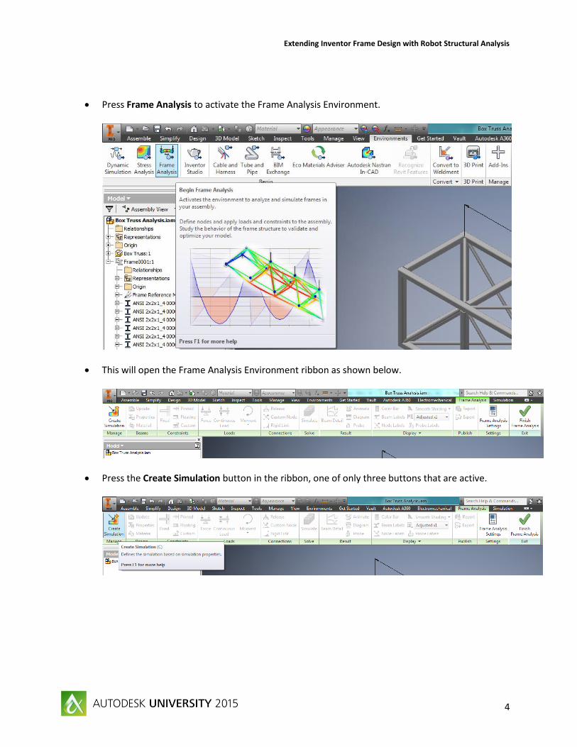
Press Frame Analysis to activate the Frame Analysis Environment.
This will open the Frame Analysis Environment ribbon as shown below.
Press the Create Simulation button in the ribbon, one of only three buttons that are active.

Extending Inventor Frame Design with Robot Structural Analysis
5
This will open the Create New Simulation dialog box.
When you press OK the following popup appears.
This is the Robot kernel taking your Frame Generator model, or model from the Content Center, and converting it to an analytical model of beam and node elements. Each member is converted to a beam element with at least a node at each end. There are also nodes created at each intersection point of one element to another. Each node will have six degrees of freedom until you limit, or constrain them. A typical analytical beam element diagram is shown below.

Extending Inventor Frame Design with Robot Structural Analysis
6
You do have the ability to add nodes in other locations if desired with the Custom Node function, but this is not a part of this course.
Each element is given a stiffness based on the cross-sectional properties brought over from Frame Generator and/or the Content Center.
These can be seen in the Beam Properties dialog box, which is accessed by pressing Properties in the Beams section of the Frame Analysis ribbon.
The following dialog box will appear.
You can change the cross-sectional properties of any member through this dialog box, by selecting the check box next to Customize. But this is not recommended for standard sections. Material properties are also brought over and attached to each created element.
You can access the material properties of any element through the Material button in the same section of the Frame Analysis ribbon.
This brings up the following dialog box.

Extending Inventor Frame Design with Robot Structural Analysis
7
Here again you can change the physical properties of any element by selecting the check box next to Customize, but this is not recommended for standard materials. If you are not content with your material selection options, you can change to a different material library or through the Material Browser in Inventor you can add materials.
In terms of the length of each element, it is based on the part length. So in our example we have a finished model so all the members ends have been trimmed or coped so there is no overlap of parts. But what the kernel sees is the individual parts to convert, so if we take one of the transverse tubes, such as ANSI 2x2x1_4 00000015.ipt, the part is 22 inches (559mm) long so the analytical element will be 22 inches (559 mm) long.
Extending Inventor Frame Design with Robot Structural Analysis
8
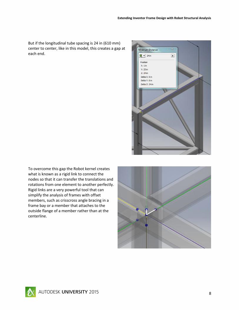
But if the longitudinal tube spacing is 24 in (610 mm) center to center, like in this model, this creates a gap at each end.
To overcome this gap the Robot kernel creates what is known as a rigid link to connect the nodes so that it can transfer the translations and rotations from one element to another perfectly. Rigid links are a very powerful tool that can simplify the analysis of frames with offset members, such as crisscross angle bracing in a frame bay or a member that attaches to the outside flange of a member rather than at the centerline.

Extending Inventor Frame Design with Robot Structural Analysis
9
You can adjust how the program creates these rigid links using the Robot kernel.
To do so press the Frame Analysis Settings button and on the Beam Model tab of the Frame Analysis Settings dialog box.
Here you can even turn off the creation of the rigid links or just how large of a gap that you want the kernel to overcome with rigid links. You can also add rigid links, through the Rigid Link button in the Connections section of the ribbon. Rigid links cannot be deleted though, they can only be suppressed.
Now, with the help of the Robot kernel inside Inventor Professional, we have a base analytical model from our design model. From here we can add constraints, loads, and other refinements and then perform the static or modal analysis. The Frame Analysis Environment in Inventor Professional is intended to be an upfront design tool that can help make design decisions early in the process. Next we are going to discuss how to make better design models for analysis shown in Inventor Professional but also applies for more advanced analysis as well. We will then open up a more realistic model of a plant to setup and perform an upfront frame analysis within Inventor Professional.
Since the Robot kernel was used to convert and analyze the Inventor model, the analytical model can be easily converted and opened in Robot for advanced analysis which we are going to show in the fourth section of this course. In the fifth section we will take a solved frame model and optimize it to find the best steel shapes that still meet our design criteria, saving money and fabrication time. All together the goal is to show you a smooth workflow that we can be used for your more complicated and real-world support structures that can be performed back at your office.

Extending Inventor Frame Design with Robot Structural Analysis
10
Better Frame Generator Models for Analysis
There are several advantages to utilizing the Frame Generator within Inventor. By creating just a simple 3D sketch you can turn that into a complete frame using standard shapes and sections from the content library. If you need to change the size of the frame, you can adjust your sketch, and the frame and its members will update. You can even drive the frame and these dimensions using an Excel spreadsheet. Once you have created the frame and added the members there is even a calculator to check sections for beam and column behavior. With the commands in the Frame section of the Design tab, you can create a beautiful frame with members that have been trimmed, coped or mitered. But this last benefit can also cause problems for the individual doing the analysis, as well as the rest of the design staff.
As mentioned in the previous section, when there is a gap between nodes, the Robot kernel will create a rigid link between them to make sure the displacements and rotations are transferred. It is then the responsibility of the engineer to ensure that the rigid links are properly setup so the analysis will be as accurate as possible. This checking, suppressing and recreating rigid links for an automatically created analytical model can be a time consuming and tedious exercise for the engineer.
But what if the analysis handoff was done earlier in the design process? What if before end treatments were applied the model was analyzed, what would be the effect? Let us go back to the Frame Generator, and remove the end treatments to go back in time to recreate the design as if it was passed to analysis earlier.
Press Finish Frame Analysis to exit the Frame Analysis Environment.
Switch to the Design tab on the ribbon and expand the Frame section, select Remove End Treatments
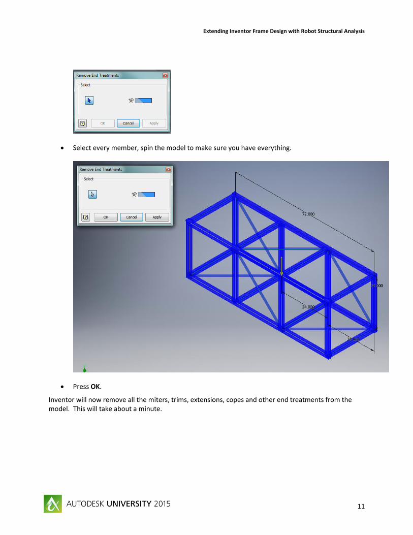
The Remove End Treatments dialog box will appear.
Extending Inventor Frame Design with Robot Structural Analysis
11
Select every member, spin the model to make sure you have everything.
Press OK.
Inventor will now remove all the miters, trims, extensions, copes and other end treatments from the model. This will take about a minute.
Extending Inventor Frame Design with Robot Structural Analysis
12
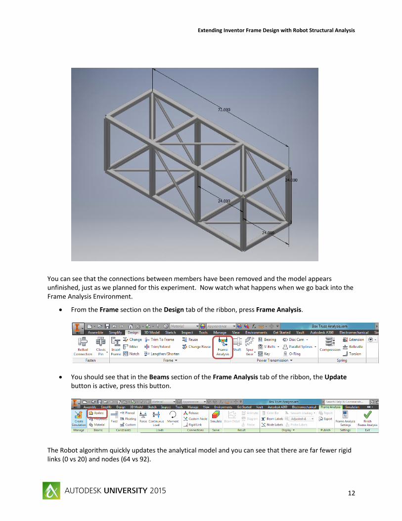
You can see that the connections between members have been removed and the model appears unfinished, just as we planned for this experiment. Now watch what happens when we go back into the Frame Analysis Environment.
From the Frame section on the Design tab of the ribbon, press Frame Analysis.
You should see that in the Beams section of the Frame Analysis tab of the ribbon, the Update button is active, press this button.
The Robot algorithm quickly updates the analytical model and you can see that there are far fewer rigid links (0 vs 20) and nodes (64 vs 92).

Extending Inventor Frame Design with Robot Structural Analysis
13
This results in a much simpler analysis for the engineer and there are many benefits to have a model like this as opposed tone with rigid links.
The model is simpler resulting in faster analysis, meaning you can try more options and ask more “what-if” questions.
The engineer can change member sizes prior to excessive modeling and cut the cost and weight of the structure.
The designer and engineer can work together on how best to connect the members of the frame, meaning less fabrication and construction time.
This is what is meant by moving the analysis early in the design phase. Now you have the chance to try different concepts, ask what if questions, and come up with an optimized design, not just a good enough design. This is the workflow that Autodesk has been promoting and is one that we can all see the cost benefit to support.
In the next section, we will take a more real world model and convert it in the Inventor Professional Frame Analysis environment to simulate a realistic workflow. The model will be seen in the raw state that we have just advocated above, but imagine what the analytical model would look like if this model was not passed off to analysis until all the members had been finished. There will be rigid links in the model, but they are used properly and will not hinder the analysis. Then we will demonstrate adding loads, constraints, and releases to perform a static and modal analysis, prior to sending the analytical model to Robot Structural Analysis in the following section.

Extending Inventor Frame Design with Robot Structural Analysis
14
Performing Frame Analysis in Inventor Professional
Now that we have discussed how to simplify your frame analysis, and move it earlier in your design workflow, we will apply it to a more realistic example. Let us open another model in Inventor Professional and then focus on one frame structure, setup the analysis, run it, and then discuss the results. The goal of this section is to review the capabilities of the Frame Analysis environment and how to perform an upfront analysis in this proposed workflow. In the following section we will show how to take this analysis information and push it over to Robot Structural Analysis to do a more extensive analysis and optimization.
Open the Inventor assembly file Skid Plant.iam from the class dataset folder, the assembly should look as shown below.
Extending Inventor Frame Design with Robot Structural Analysis
15
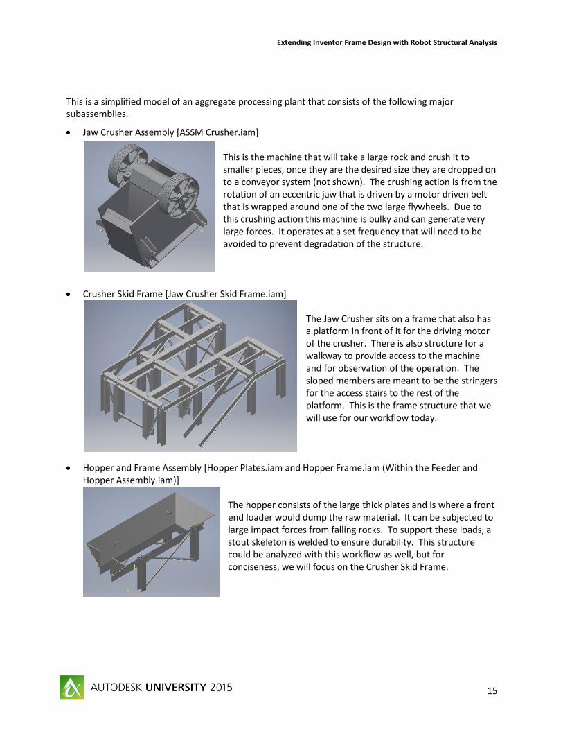
This is a simplified model of an aggregate processing plant that consists of the following major subassemblies.
Jaw Crusher Assembly [ASSM Crusher.iam] This is the machine that will take a large rock and crush it to smaller pieces, once they are the desired size they are dropped on to a conveyor system (not shown). The crushing action is from the rotation of an eccentric jaw that is driven by a motor driven belt that is wrapped around one of the two large flywheels. Due to this crushing action this machine is bulky and can generate very large forces. It operates at a set frequency that will need to be avoided to prevent degradation of the structure.
Crusher Skid Frame [Jaw Crusher Skid Frame.iam] The Jaw Crusher sits on a frame that also has a platform in front of it for the driving motor of the crusher. There is also structure for a walkway to provide access to the machine and for observation of the operation. The sloped members are meant to be the stringers for the access stairs to the rest of the platform. This is the frame structure that we will use for our workflow today.
Hopper and Frame Assembly [Hopper Plates.iam and Hopper Frame.iam (Within the Feeder and Hopper Assembly.iam)]
The hopper consists of the large thick plates and is where a front end loader would dump the raw material. It can be subjected to large impact forces from falling rocks. To support these loads, a stout skeleton is welded to ensure durability. This structure could be analyzed with this workflow as well, but for conciseness, we will focus on the Crusher Skid Frame.

Extending Inventor Frame Design with Robot Structural Analysis
16
Vibratory Feeder Assembly [Feeder Assm.iam (Within the Feeder and Hopper Assembly.iam)] The vibratory feeder is a conveying machine for the rocks that are dumped in to the hopper, where it sits below. The bars near the jaw are to separate the smaller rocks that would pass through a bypass chute (that is not present) to a conveyor system (that is also not shown). This piece of equipment is subjected to impact loads from falling rocks similar to the hopper and loads from a large eccentric vibratory action to excite the rocks.
Feeder Skid Frame [Feeder Skid Frame.iam] This frame supports the loads from the feeder and the hopper. In our example it is a very compact structure, so we will not use this in our workflow example.
This is not a complete plant, since there are several components missing, but should be viewed as a layout that has not been finalized, to allow for easier analysis. It is setup this way so that it follows the guidelines discussed previously. Had we waited to perform the analysis until the model was nearly complete this would limit our ability to make changes, including optimization. Thus, would make the analysis more time consuming and cumbersome due to these extra rigid links.
So there are actually three frame structures that we could analyze for this plant, and we could do all three together. But, for the purpose of this lab we will focus on the Crusher Skid Frame.

Extending Inventor Frame Design with Robot Structural Analysis
17
Select this frame in the Graphics Window and right-click the mouse to bring up the context menu. Select Open.
The Jaw Crusher Skid Frame.iam will open in a new tab.

Extending Inventor Frame Design with Robot Structural Analysis
18
Go to the Environments tab and start the Frame Analysis Environment.
Press Create Simulation, the Create New Simulation dialog box will appear.
Go to the Model State tab.
Rather than opening one of the sub-assemblies, we could have made a Level of Detail that would suppress the machines, and so we would be left with just the structural frames. This would have been

Extending Inventor Frame Design with Robot Structural Analysis
19
the method we would employ if we were to study the plant with one analysis workflow. But for the sake of time and simplification we are just focusing on the Jaw Crusher Skid Frame.
Press OK, to create a Static Analysis.
At this point, we would start by reviewing the materials to ensure they were properly identified. But since this model was created by the speaker, the materials specified can be assumed to be adequate. When we move to Robot Structural Analysis we will further refine the materials by profile type.
Under the Settings section, press Frame Analysis Settings.
The dialog box below will open.
There is a feature in the Frame Analysis Environment known as the Heads Up Display (HUD), this can help speed up the selection of nodes and elements so that an analysis can be setup quickly once you know how to use the environment. But, it can be a deterrent during the learning process. So it is recommended that you turn this off until you become very familiar with the workflow of each button.

Extending Inventor Frame Design with Robot Structural Analysis
20
Deselect the check box next to Use HUD in Application in the dialog box.
Please note that the HUD is more than the default, it can turn back on even when you do not want it to. If it reactivates, which you will notice, just come back to this dialog box and turn it off again. So, you will have to make sure it is deactivated until you are comfortable enough to perform the simulation with it turned on.
Press OK to close the dialog box.
Now we will add constraints to the model. Constraints are applied to keep the model from rigidly moving. For our model we will apply two types of constraints, Pinned and Floating Pinned. The Pinned constraint allows for rotation, but does not allow for displacement. A Fixed constraint is sometimes used on frames, and caution should be exercised before using this kind of constraint. When a Fixed constraint is assumed, the rotations must be restricted, and therefore moments will be generated. If we look at a typical frame base plate connection with anchor bolts, as shown below, it is difficult to generate moment resistance from this type of connection.
If you do use a fixed constraint, make sure you discuss this with your foundation design team. We will use a Pinned Constraint to begin with, in our model.

Extending Inventor Frame Design with Robot Structural Analysis
21
Under the Constraints section on the Frame Analysis tab, select Pinned.
Select the bottom front node on the left side.
Press Apply in the dialog box, to place the constraint.
We will now constrain every vertical column where it intersects the same XZ plane. Repeat these steps for every node, pressing Apply after each selection. Do not do this for the sloped stair stringers. Your model should look similar to below.

Extending Inventor Frame Design with Robot Structural Analysis
22
As stated above, the sloped elements are intended to be stair stringers so we only want to constrain them so they cannot move in the Y direction (vertical), so we will apply a roller constraint, in Inventor Professional this is called a Floating Pinned Constraint. It allows for rotation about all three axes and translation in one direction.
In the Constraints section again, select Floating.
Extending Inventor Frame Design with Robot Structural Analysis
23
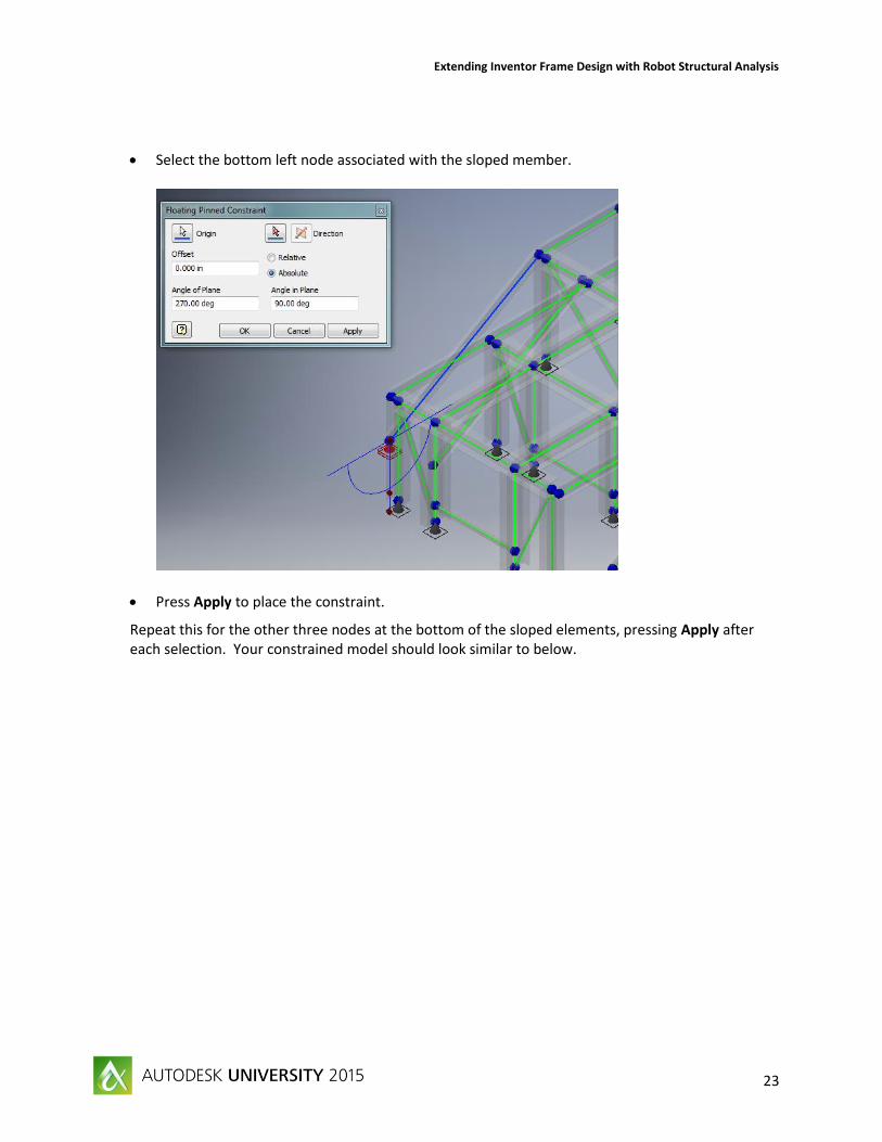
Select the bottom left node associated with the sloped member.
Press Apply to place the constraint.
Repeat this for the other three nodes at the bottom of the sloped elements, pressing Apply after each selection. Your constrained model should look similar to below.

Extending Inventor Frame Design with Robot Structural Analysis
24
Now that the model is constrained, we will apply loads, in the spirit of preliminary analysis we are going to focus on the large loads from the Jaw Crusher since these are much larger than the other loads and this will give us an idea on how adequate the structure is for these loads. As can be seen by the yellow arrow that is already present in our model, gravity is also being applied. If you want to edit or suppress gravity, you can do so in the browser under the Loads folder.
The crusher machine is very large and heavy, weighing around 130,000 pounds. So we are going to divide that number by four and apply 33,000 pounds at the four connection points.
In the Loads section of the ribbon, press Force.
Extending Inventor Frame Design with Robot Structural Analysis
25
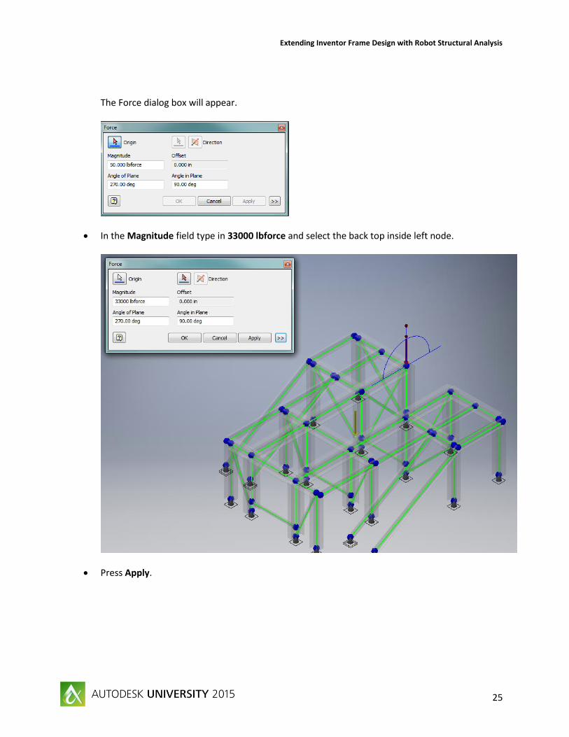
The Force dialog box will appear.
In the Magnitude field type in 33000 lbforce and select the back top inside left node.
Press Apply.

Extending Inventor Frame Design with Robot Structural Analysis
26
Repeat this to get all four nodes in the back of the Jaw Crusher Skid Frame, pressing Apply after each load application.
Now that we have applied the dead load of the Jaw Crusher, next we will apply the live load. The flywheels are driven and it creates a cyclic live load that can make the jaw “lunge” forward. To approximate this we will apply a downward force on one side of the crusher, and an upward force on the other side. We will also apply some lateral live loads. This is just a sample of the loads generated by the crusher and is being used for demonstration purposes only.
With the Force dialog box still open, change the Magnitude field to 22000 lbforce. Apply to the back two nodes, pressing Apply after each selection. These are our downward live loads.
Press the button “>>” in the dialog box and the box will expand. Select the checkbox next to Vector components. In the field for FY, change the magnitude (22000 lbforce) from negative to positive, then apply to the other two nodes at the Jaw Crusher connection points. These are our upward live loads.

Extending Inventor Frame Design with Robot Structural Analysis
27
Next, in the dialog box, change the Fy magnitude to 0 lbforce and in the field for Fz type in the value -13000 lbforce. Apply this load to the last two nodes we applied the upward vertical force too.
Extending Inventor Frame Design with Robot Structural Analysis
28
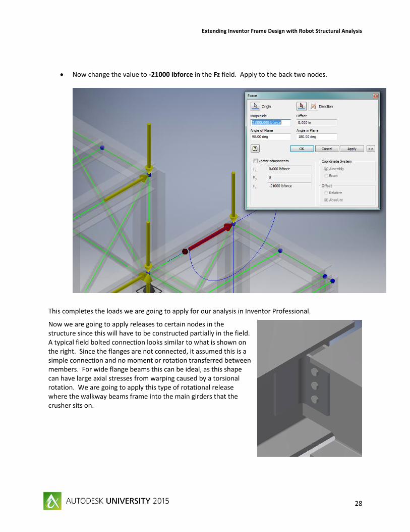
Now change the value to -21000 lbforce in the Fz field. Apply to the back two nodes.
This completes the loads we are going to apply for our analysis in Inventor Professional.
Now we are going to apply releases to certain nodes in the structure since this will have to be constructed partially in the field. A typical field bolted connection looks similar to what is shown on the right. Since the flanges are not connected, it assumed this is a simple connection and no moment or rotation transferred between members. For wide flange beams this can be ideal, as this shape can have large axial stresses from warping caused by a torsional rotation. We are going to apply this type of rotational release where the walkway beams frame into the main girders that the crusher sits on.
Extending Inventor Frame Design with Robot Structural Analysis
29
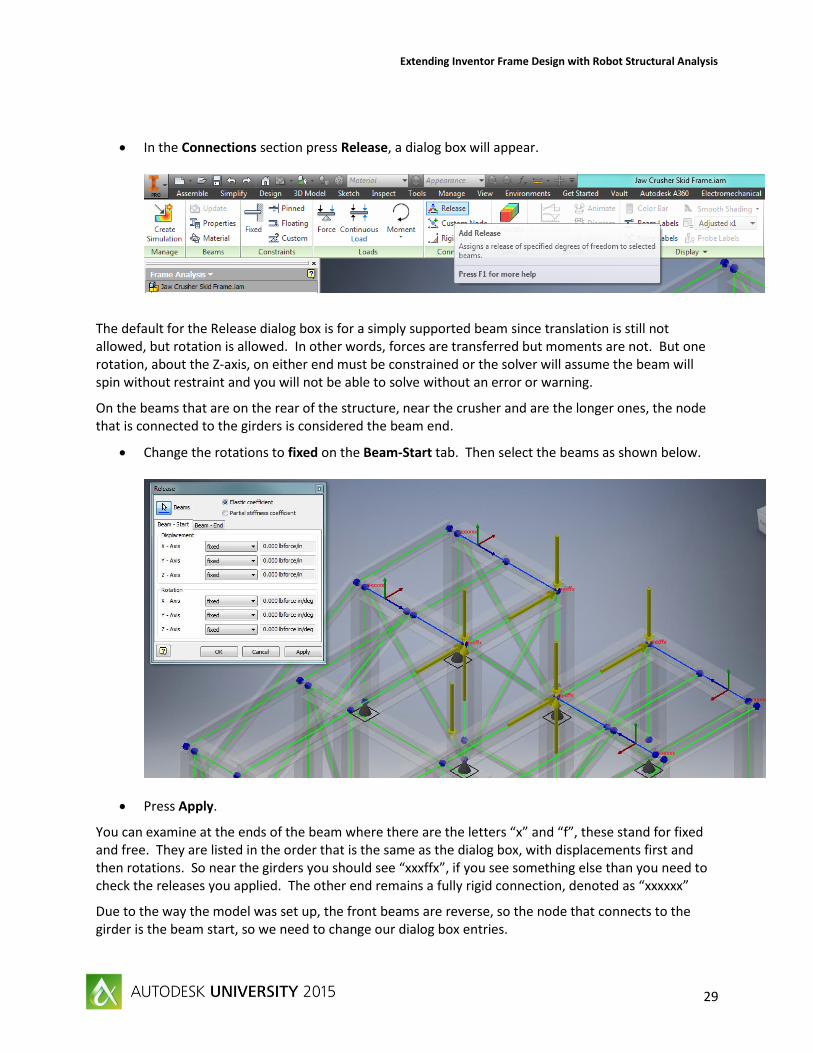
In the Connections section press Release, a dialog box will appear.
The default for the Release dialog box is for a simply supported beam since translation is still not allowed, but rotation is allowed. In other words, forces are transferred but moments are not. But one rotation, about the Z-axis, on either end must be constrained or the solver will assume the beam will spin without restraint and you will not be able to solve without an error or warning.
On the beams that are on the rear of the structure, near the crusher and are the longer ones, the node that is connected to the girders is considered the beam end.
Change the rotations to fixed on the Beam-Start tab. Then select the beams as shown below.
Press Apply.
You can examine at the ends of the beam where there are the letters “x” and “f”, these stand for fixed and free. They are listed in the order that is the same as the dialog box, with displacements first and then rotations. So near the girders you should see “xxxffx”, if you see something else than you need to check the releases you applied. The other end remains a fully rigid connection, denoted as “xxxxxx”
Due to the way the model was set up, the front beams are reverse, so the node that connects to the girder is the beam start, so we need to change our dialog box entries.

Extending Inventor Frame Design with Robot Structural Analysis
30
Now change the Rotation releases for the X-Axis and the Y-Axis from fixed to uplift none on the Beam - Start tab. Now change to the Beam - End tab and change those X- and Y- Axis rotations to fixed. Select the members shown below.
Press Apply for the changes to take place.
Next we will change the connections for our bracing, which is intended to be tubes connected with center plates, so this is assumed to be a pinned connection on both ends. We will remove rotation on both ends, except for about the Z axis, since we do not want to allow the member to spin on its own longitudinal axis.

Extending Inventor Frame Design with Robot Structural Analysis
31
Now change back the rotations for X- and Y-Axis to uplift none. This will create a simply supported brace, so apply to the diagonal braces as shown below.
Press OK to make the changes.
We are now ready to run the preliminary analysis.
Press Simulate in the Solve section on the ribbon to run the structure through the analysis. The displaced shape representation and the color map of displacements is shown initially.
The Robot kernel solves the analytical model very quickly, since there are fewer members because of our reduction in the use of rigid links.

Extending Inventor Frame Design with Robot Structural Analysis
32
In the Browser, expand the Results folder, then the Normal Stresses folder, and select Smax by double clicking on it. Your Graphics Window should look similar to below.
As we can see there is not much stress on the members, but this is an early analysis so we are not going to change any sizes yet. Take this opportunity to look at other results provided by the Frame Analysis environment, there are some very helpful result presentations.
Beam Detail This allows you to select a member and then generate the shear and moment diagrams, or other representations.

Extending Inventor Frame Design with Robot Structural Analysis
33
Diagram This places the shear and moment diagrams on all the members in the model for comparison.
Now that we have shown from a quick preliminary static analysis that the structure is adequate as designed, we will do a Nodal Analysis to ensure the structure does not have any natural frequencies near the equipment operating speeds.
In the browser, right-click on Simulation:1 and select Copy Simulation.
Simulation:2 appears in the browser, right-click on Simulation:2 and select Edit Simulation.
The Edit Simulation dialog box appears (which looks very similar to the Create Simulation dialog box) Select the radial button next to Modal Analysis. Change the Maximum Number of Modes to 24 and the Number of Iterations to 20. Press OK to close the dialog box.

Extending Inventor Frame Design with Robot Structural Analysis
34
Press Simulate in the Solve section of the Ribbon.
When the analysis completes, expand the Results folder and then the Modal Frequency folder. This displays the first 24 natural frequencies of the structure. You can double-click on any or all of them to have the deformed shape and then animate them. We could have done more frequencies, but this provides us with first 7 natural frequency groupings for the structure and we could compare these with our operating equipment’s rotational speed to avoid correlation.
This completes our preliminary analysis in Inventor Professional, this would have made us aware of any major flaws in the design and allows us to ask some of those “what if” type questions. The next step is to send the model to Robot and analyze per the design code loads and load combinations. RSA software enables this code checking ability and optimization. It also allows us to do more advanced load analysis including wind, seismic, rain, snow, or other dynamics analysis types. After the analysis in Robot, we will then use the advanced software to optimize it for the most efficient section.

Extending Inventor Frame Design with Robot Structural Analysis
35
Transferring Inventor Professional Analysis Model to Robot Structural Analysis
Now that we have done a preliminary analysis within Inventor Professional, we will move on to the more advanced analysis with Robot Structural Analysis Professional. Robot is an advanced structural engineering applications that can perform complicated load analysis with robustness.
Wind loading per the design codes, but also with a virtual wind tunnel based on Autodesk CFD technology.
Seismic design Advanced dynamic analysis including Pushover and Footfall. Snow and soil pressure loadings Prestressing forces Moving loads
The transfer of the model from Inventor to Robot is easy since, as stated previously, the same kernel is used in both simulation tools. But, it is important that once the model is in Robot that we follow a workflow to make sure that your structure will be able to undergo a code check and optimization. The code check and optimization workflow will follow in the section after this one.
In the Publish section of the Frame Analysis ribbon, press the Export button. The dialog box shown below appears.
In this dialog box there are two options in the upper portion. The first option is to export the analytical model directly in to the Robot application, which is ideal if you have both software titles on your machine. The option below is to create a Robot file, this allows for the sharing of analysis setup and results within your organization. The lower two options allow for the creation of a new Robot file, the only option currently available for this demonstration, or to modify an existing Robot file with the changes made in the Inventor model.
The default settings are fine, so leave them as shown above and press OK.

Extending Inventor Frame Design with Robot Structural Analysis
36
The conversion proceeds until the following dialog box appears regarding the vertical axis. There should not be an issue with changing the vertical axis from Y to Z, the default for Robot.
Press OK
An export report appears describing the export and if there were any issues. Press Close to close this export report. The model should appear in the Robot Structural Analysis application, which may be minimized in your windows taskbar. The Robot model should look similar to what is shown below.
Within the Robot Interface there are a few things I would like to highlight that will make the rest of this workflow demonstration go much better.
Text Menu
Toolbar

Extending Inventor Frame Design with Robot Structural Analysis
37
Layout Selector
Understanding how to leverage this tool is critical for success with navigating the Robot Interface. It allows for you to move from setup, reviewing results, through code checking and design with your model. Viewcube
The Autodesk standard for manipulating the way we are looking at the model.
The first step when working with Robot Structural Analysis is to setup the proper language and codes.
Go to the Tools menu in the Text Menu and select Preferences…
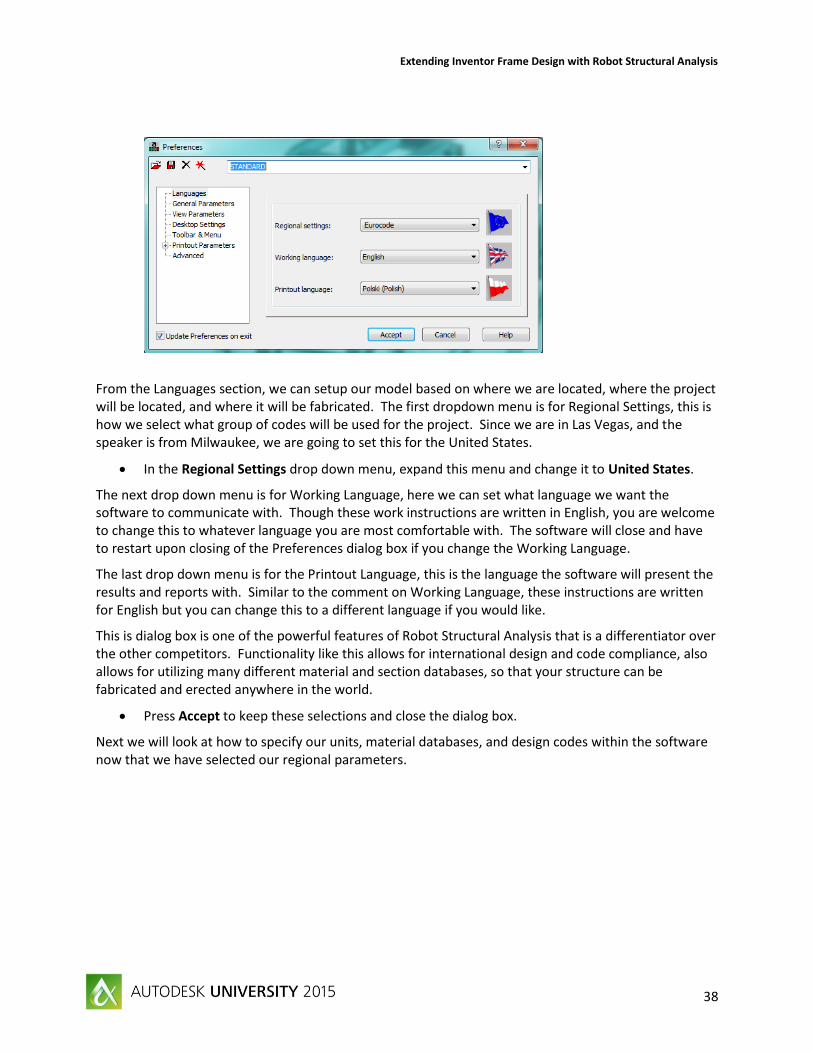
The following dialog box opens in the application.
Extending Inventor Frame Design with Robot Structural Analysis
38
From the Languages section, we can setup our model based on where we are located, where the project will be located, and where it will be fabricated. The first dropdown menu is for Regional Settings, this is how we select what group of codes will be used for the project. Since we are in Las Vegas, and the speaker is from Milwaukee, we are going to set this for the United States.
In the Regional Settings drop down menu, expand this menu and change it to United States.
The next drop down menu is for Working Language, here we can set what language we want the software to communicate with. Though these work instructions are written in English, you are welcome to change this to whatever language you are most comfortable with. The software will close and have to restart upon closing of the Preferences dialog box if you change the Working Language.
The last drop down menu is for the Printout Language, this is the language the software will present the results and reports with. Similar to the comment on Working Language, these instructions are written for English but you can change this to a different language if you would like.
This is dialog box is one of the powerful features of Robot Structural Analysis that is a differentiator over the other competitors. Functionality like this allows for international design and code compliance, also allows for utilizing many different material and section databases, so that your structure can be fabricated and erected anywhere in the world.
Press Accept to keep these selections and close the dialog box.
Next we will look at how to specify our units, material databases, and design codes within the software now that we have selected our regional parameters.

Extending Inventor Frame Design with Robot Structural Analysis
39
Select Job Preferences…, which can be accessed from the Tools menu in the Text Menu and is right below the previously selected Preferences…
A dialog box similar to below will appear in the application.
On the left hand side, we can move through and make the preference selections for the model. We will start with Units and Formats. Here you can select Metric or Imperial units for your analysis.

Extending Inventor Frame Design with Robot Structural Analysis
40
Press Imperial to make sure the analysis is done with this unit system.
A dialog box may appear asking to confirm your selection, press Yes to close it.
If you want to further refine what units are used you can go to the subcategories for Dimensions, Forces, and Other.
Next is the Databases section, where with the subcategories you can select the section databases to utilize. Since our frame is steel, we will only go to the Steel and timber sections subcategory.
Make sure that the AISC 14.0 database is selected, in the Steel and timber sections subcategory. (This can be seen in the first snapshot of this dialog box above.)
Next we will focus on how to set the design code that you want to comply with, how to generate our loads, and the applicable load combinations, found under the Design Code category. The main header is where we select the material specific design codes. The one subcategory is for Loads, which is what code we want to use for our loads. We want select ASCE 7 as our load source since, this is a common standard for structural loads and load combinations utilized in the United States.
Next select in the side browser Design Codes and then Loads.
Make sure the Code combinations is set as LRFD ASCE 7-10, as shown below.
Extending Inventor Frame Design with Robot Structural Analysis
41
Press OK to close the dialog box.
After establishing the proper codes and material databases, we need to establish the materials and make sure they are properly applied to our frame. When the structure comes in from Inventor, it is given a generic material, so we need to assign the correct materials.
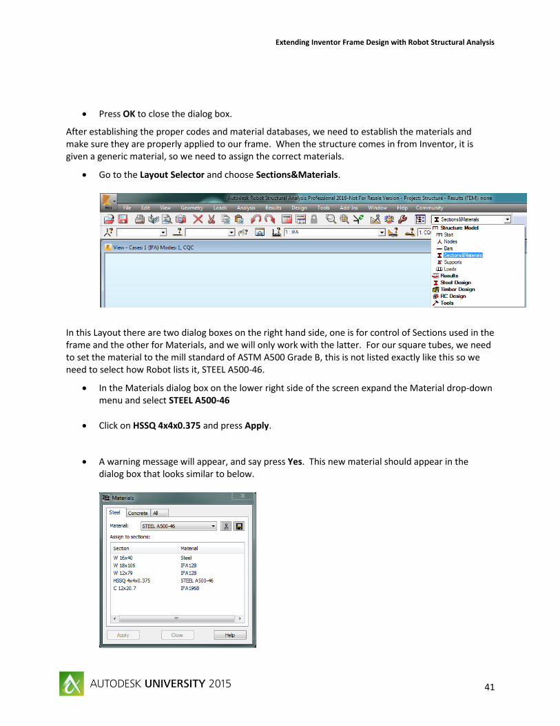
Go to the Layout Selector and choose Sections&Materials.
In this Layout there are two dialog boxes on the right hand side, one is for control of Sections used in the frame and the other for Materials, and we will only work with the latter. For our square tubes, we need to set the material to the mill standard of ASTM A500 Grade B, this is not listed exactly like this so we need to select how Robot lists it, STEEL A500-46.
In the Materials dialog box on the lower right side of the screen expand the Material drop-down menu and select STEEL A500-46
Click on HSSQ 4x4x0.375 and press Apply.
A warning message will appear, and say press Yes. This new material should appear in the dialog box that looks similar to below.

Extending Inventor Frame Design with Robot Structural Analysis
42
Next we need to set the material for our wide flange beams to ASTM A992, in Robot this is listed as STEEL A992-50.
Change the Material in the drop down to A992-50.
Select the sections W18x106 and W12x79, and pressing Apply.
The same warning message will appear and still press Yes.
Channels are typically sourced as ASTM A36 or ASTM A709, for our demonstration we will set the material as STEEL A36.
Once all the materials have been changed, the Materials dialog box should look similar to below.
One way that Robot allows for input and displays results is in tabular format, which can be exported to a CSV file for easy integration with your spreadsheet program. The list of tables available are in the View menu on the Text Menu.
Under the View menu on the Text Menu and select Tables…
The Tables: Data and Results dialog box will appear. We will be focused on the Bar table so we can ensure our material changes have been applied.
Check the box next to Bars and Press OK to open the Bar table.

Extending Inventor Frame Design with Robot Structural Analysis
43
A table of all the elements that were brought over from Inventor should be listed. Review the table and make sure that our changes to the Material is reflected in this table for each of the members.
Next with this table we will set the type of bar for the elements in our frame.
Highlight the Type column and right-click and select Fill Special… the following dialog box will appear.
This is where you select the type for each element. There are different requirements based on the classification (beam, column, cable, and bar) of the member.
Beam Subject to typically bending loads, but can be exposed to buckling effects for longer slender members.
Column Typically a member subjected to large compressive loads and can buckle in different manners based on its support criteria. These can also be subjected to bending as well.

Extending Inventor Frame Design with Robot Structural Analysis
44
Cable A member that can only act in tension as it has no capacity for compressive loads.
Simple Bar The general catch all for a member, but these do not go through the code checking for the beam or column buckling or other failure analysis.
We are trying to keep our workflow simple, so we will be selecting the Simple Bar model, but you would want to specify a more fitting description for your frames. The types are further broken down based on materials (reinforced concrete, timber, or metal) since this can have an effect of the relevant failure modes.
Select Simple bar.
Press OK to leave this dialog box.
Make sure that all the bars are listed as a Simple bar Type.
Now we will establish our load types, these are utilized to create load combinations. Typically a live load is less predictable than a dead load, such as self-weight, so the codes apply a larger factor to the live load. There are also load types and combinations that include them for rain, snow, wind, and seismic loadings. For our example we have only dead and live loads, since there are more live loads we will classify these first.
In the Layout Selector switch to Loads.
On the right-hand side in this layout there should be a dialog box that is called Load Types and at the bottom is a table of all the Loads.
In the field next to Label, in the Load Types dialog box, type in LL1.
Change the Nature from dead to live, in the drop down menu.
Change the Name to LL1 as well, then press Modify the dialog box should look similar to below.

Extending Inventor Frame Design with Robot Structural Analysis
45
We have assigned all the loads that were transferred from Inventor as Live Loads, since this is not the case we will now add dead load as a Load Type.
In the Load Types dialog box change the Nature to dead, and this will change the Label and Name to DL1.
Press Add to complete this addition.
In the Loads table at the bottom of the Layout, change the Case for the first five entries to DL1
These are self-weight of the structure and the weight of the Jaw Crusher. Your Loads table should look similar to below.
As an example, we could add additional loading within Robot.
Go into the Loads menu on Text Menu and select Load Definition… the dialog box below appears.

Extending Inventor Frame Design with Robot Structural Analysis
46
We are going to add the live loading from the motor that drives the Jaw Crusher. We are going to assume that we can apply this as four point loads that are each 3 kips.
Press the Nodal Force button, which is outlined below.
Once selected the following dialog box appears that allows for the input of forces based on model axis orientations.
Change the value for F (kip) for Z: to 3.0.
Press Add, which will close the dialog box and allow us to select nodes for application.

Extending Inventor Frame Design with Robot Structural Analysis
47
Zoom in on the model and select nodes 2, 4, 7, 18 as shown below.
This action added the loading to the structure and can be seen in the Loads table at the bottom of the screen. It does not matter if you apply the loads in this manner, or if you were to go back and redefine the nodal load and then select each node, the result will be the same.
You can add additional loadings, by first selecting the load case in the Load Types dialog box and then activating the Load Definition dialog box. Some additional loads we could add are listed below, if you wanted to try them on your own.
Dead load from the walkways of 0.5 kip/ft on areas where there would be a platform and along the stairway stringers.
Dead load from the handrails of 0.5 kip/ft on members where there would be a handrail and on the stairway stringers.
Live load of 1 kip/ft for the platforms and the stairs.
Now that we have defined our Load Types we need to establish our Load Combinations.
Go to the Loads menus in the Text Menu and select Automatic Combinations…

Extending Inventor Frame Design with Robot Structural Analysis
48
The Load Case Code Combinations dialog box appear.
The Combinations according to code: should specify LRFD ASCE 7-10.
Select the radial button next to Full automatic combinations.
This will generate 3 load combinations to be used in the analysis, if we had added more load cases, this number would be larger.
Press OK to clear the dialog box.
We are now ready to run the analysis. Press the Calculations button in the Toolbar that looks like a calculator.
Extending Inventor Frame Design with Robot Structural Analysis
49
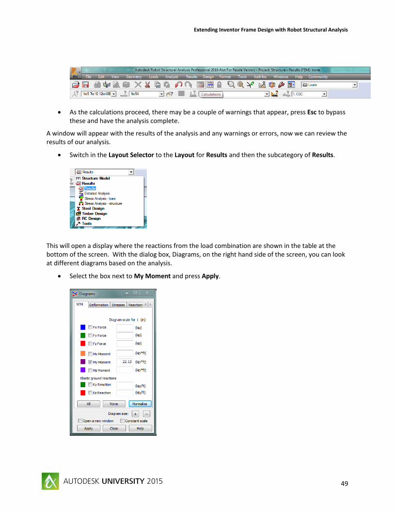
As the calculations proceed, there may be a couple of warnings that appear, press Esc to bypass these and have the analysis complete.
A window will appear with the results of the analysis and any warnings or errors, now we can review the results of our analysis.
Switch in the Layout Selector to the Layout for Results and then the subcategory of Results.
This will open a display where the reactions from the load combination are shown in the table at the bottom of the screen. With the dialog box, Diagrams, on the right hand side of the screen, you can look at different diagrams based on the analysis.
Select the box next to My Moment and press Apply.

Extending Inventor Frame Design with Robot Structural Analysis
50
You should see the moment diagram displayed on each member in your model. We can change to other results displays in the Results menu in the Toolbar. There are many different types of result representations are available, so this is a good chance to explore these. Now that we have results from a completed analysis, we can perform the steel design and optimization in the next section.

Extending Inventor Frame Design with Robot Structural Analysis
51
Optimizing Steel Sections with Robot Structural Analysis
With the completion of our analysis, we can now use Robot to perform steel design and optimization as we will show in this section. We will create parameters for our design and then have the program do a code check and suggest the most efficient structural steel shapes. To do this we need to switch to the Steel/Aluminum Design layout.
Switch in the Layout Selector to Steel Design and then Steel/Aluminum Design.
This will launch the Steel/Aluminum Design layout. There are two dialog boxes on the right hand side, the one on top being Definitions. This is where we can, on a member by member basis or with groups, which is the method we will employ in this example, establish parameters for our design. The dialog box on the bottom, Calculations, is where we can define and run code verifications and optimizations. There is another dialog box that will be helpful during this process so we will need to launch the Bar Selection dialog box.
Underneath the Toolbar is the Bar Selection button, it has a beam element with two nodes and a question mark.
This will launch the Selection dialog box that we will use for creating design groups.
Extending Inventor Frame Design with Robot Structural Analysis
52
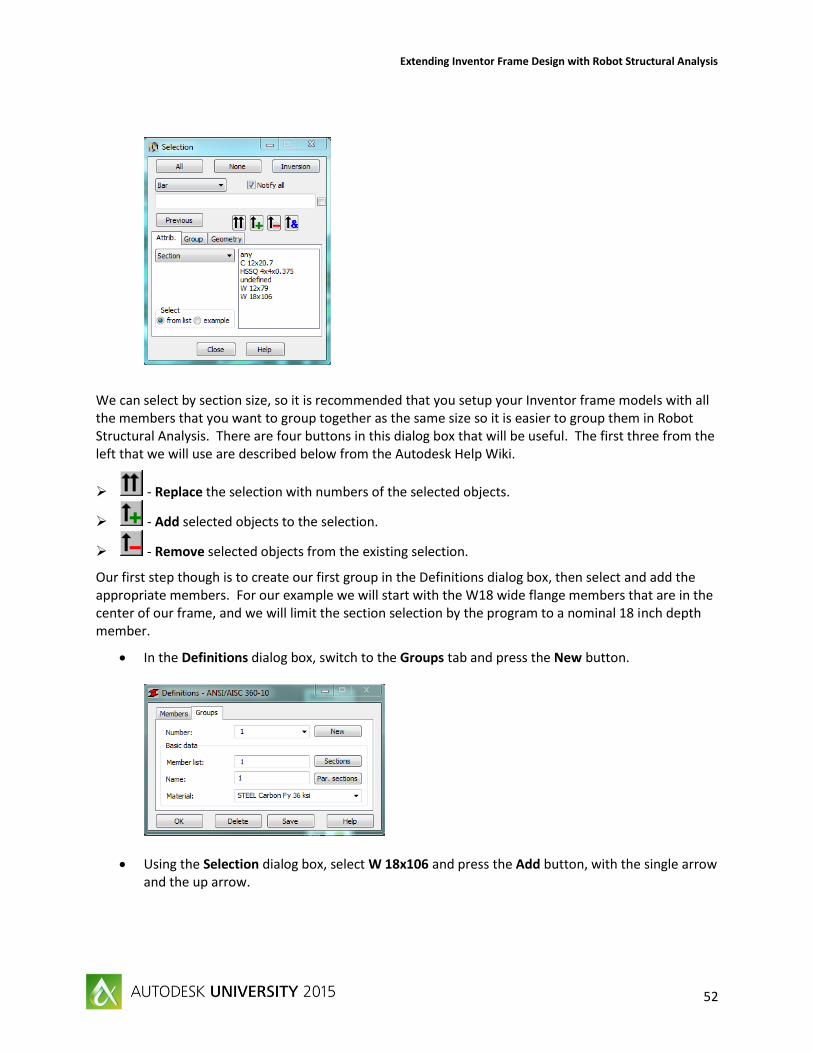
We can select by section size, so it is recommended that you setup your Inventor frame models with all the members that you want to group together as the same size so it is easier to group them in Robot Structural Analysis. There are four buttons in this dialog box that will be useful. The first three from the left that we will use are described below from the Autodesk Help Wiki.
- Replace the selection with numbers of the selected objects.
- Add selected objects to the selection.
- Remove selected objects from the existing selection.
Our first step though is to create our first group in the Definitions dialog box, then select and add the appropriate members. For our example we will start with the W18 wide flange members that are in the center of our frame, and we will limit the section selection by the program to a nominal 18 inch depth member.
In the Definitions dialog box, switch to the Groups tab and press the New button.
Using the Selection dialog box, select W 18x106 and press the Add button, with the single arrow and the up arrow.

Extending Inventor Frame Design with Robot Structural Analysis
53
This selects all the members at this size.
Highlight and copy the sections that were found by the selection tool, 1to10.
In the Definitions dialog box, paste these sections in to the field next to Member list:.
In the field next to Name: type in Main Jaw Structure.
In the dropdown for Material: select STEEL A992-50…
A warning may appear but just press Yes.
Next press the button Sections, this will bring up a dialog box that we can select shapes to be included.

Extending Inventor Frame Design with Robot Structural Analysis
54
Select the I-beam button at the top, the second from the left.
Then check the box next to AISC 14.0 in the Databases: field.
In the Section families: field select W, but not the checkbox.
In the Sections: field highlight all the W 18 sections, and they will be added to the Selected sections: field. Your dialog box should look similar to below.
Press OK to close this dialog box, now we will switch back to the Definitions dialog box.
Press Save on the Definitions dialog box.
Now we will establish the parameters for the walkway support members that are W12 wide flange members. We will also limit these to a nominal 12 inch depth.

Extending Inventor Frame Design with Robot Structural Analysis
55
In the Selection dialog box, with the section W 12x79 highlighted, press the Replace button with the two arrows. This removes this section from the list.
Highlight the members listed and copy them to the clipboard.
Press New on the Definitions dialog box.
Paste the members from the Selection dialog box into the Member list: field.
In the Name: field type in Walkway Supports, this could cause a warning message to pop and so just press Yes.
Press the Sections button, similar to before select the I-beam button
Then press Delete all to remove the W18 sections from the selected grouping.
Add the W12 shapes from the AISC 14.0 database. Your dialog box should look similar to below.

Extending Inventor Frame Design with Robot Structural Analysis
56
Press OK to close the dialog box.
Press Save on the Definitions dialog box.
You could at this point add two more groups based on the parameters below. Make sure to press Save after each group is created.
o Group 3: Walkway Perimeter Current Section – C 12x20.7 Material – A36 Steel Sections – C 12
o Group 4: Bracing Current Section – HSSQ 4x4x0.375 Material – A500-46 Sections - HSSQ 4x4
Now we will switch to the Calculations dialog box to perform the calculations.
Select the radial button next to Code group design: and in the field next to it type 1to4.
This will tell the program to do all four groups that we have created, if you have not created all the groups you can change this to the applicable input.
Check the checkbox next to Optimization and then press Options. The following dialog box appears.

Extending Inventor Frame Design with Robot Structural Analysis
57
This is where we can drive the optimization, we have already limited our sections for each group, but we could optimize each group individually and then specify section size from this dialog box.
Check the box next to Weight, to find the lowest weight section.
Press OK to close the dialog box. The Calculations dialog box should look similar to below.
Press the Calculations button to begin the optimization.
Extending Inventor Frame Design with Robot Structural Analysis
58
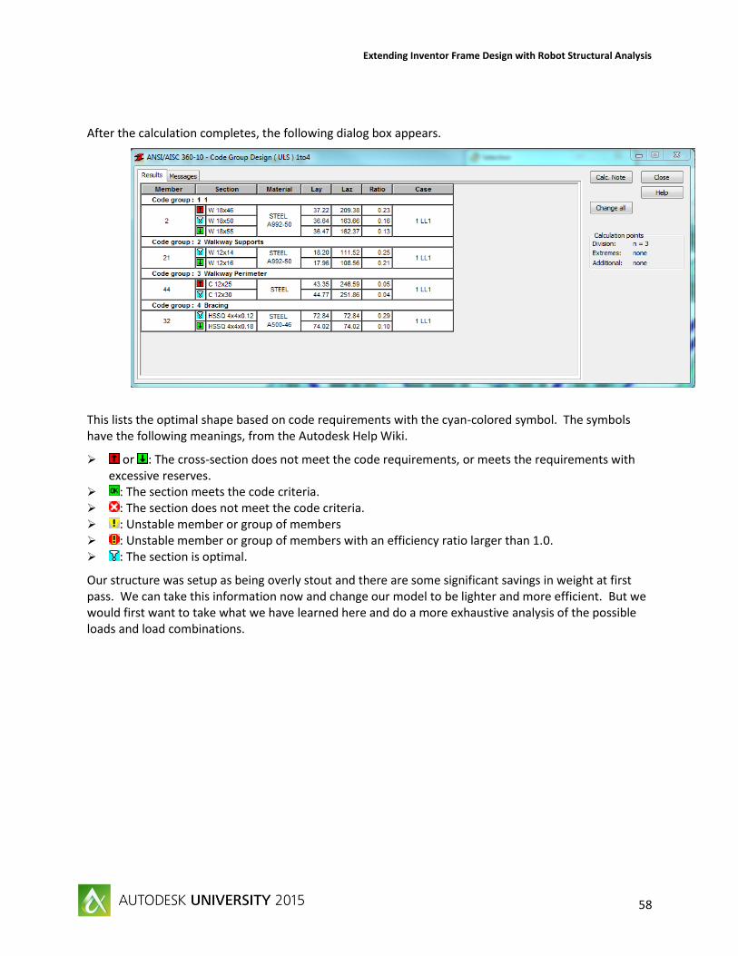
After the calculation completes, the following dialog box appears.
This lists the optimal shape based on code requirements with the cyan-colored symbol. The symbols have the following meanings, from the Autodesk Help Wiki.
or : The cross-section does not meet the code requirements, or meets the requirements with excessive reserves.
: The section meets the code criteria. : The section does not meet the code criteria. : Unstable member or group of members : Unstable member or group of members with an efficiency ratio larger than 1.0. : The section is optimal.
Our structure was setup as being overly stout and there are some significant savings in weight at first pass. We can take this information now and change our model to be lighter and more efficient. But we would first want to take what we have learned here and do a more exhaustive analysis of the possible loads and load combinations.

Extending Inventor Frame Design with Robot Structural Analysis
59
Summary
So through this demonstration we have taken a frame structure, which was in generated in Inventor Professional, and optimized it to find more efficient sections. During the process we have picked up a few key points as listed below.
Simplify our Inventor frame models for an easier and faster analysis. We performed an example where we reduced the number of rigid links, thus simplifying the analysis and the results interpretation. To achieve this we need to move the analysis forward in the design process, which in turn will result in more refinement and improved designs. This is not just true with frame analysis models, but holds true for all simulation models. The simpler the model, the more efficient the analysis.
Perform analysis early in the design process to invite more options. With the analysis tools that are in Inventor, and Revit, we can perform upfront simulations to help make better decisions. The tools available are not just limited to frame analysis, but offer many different types of simulation analysis. These tools are design to be simplified, and with guidance can be utilized by more design personnel.
Inventor Professional and Robot Structural Analysis Professional have a link to transfer analysis data. We were able to take our completed frame analytical model, with constraints, releases, loads, and member information and push it to Robot for further analysis. Within the Autodesk portfolio, there are many opportunities to push analytical data. Robot can accept information not just from Inventor, but also Advance Steel and Revit. Inventor can also push information to Simulation Mechanical and CFD. So with Autodesk, your data is not static in one program, but can be passed for improved workflows and results.
Advanced analysis tools are available in Robot Structural Analysis. We demonstrated the optimization tool within Robot and the benefits it can bring to your company. But there are many more features with RSA, including steel connection design and the virtual wind tunnel analysis. The common theme with Autodesk simulation is that there are products with incredible capabilities, such as Robot, but also tools that can be used for upfront analysis and quick decision making, and the data from these levels can be shared.
Sharing the optimized structure. So now that we have our performed our optimization there are two paths that can be followed for getting your analysis information back to a design tool. For larger structures and frames, it is best to have the information transferred to a tool such as Advance Steel that can process the fabrication data. If it is a smaller structure, and you want to push it back to Inventor, we can help with that. At MasterGraphics, we have the programming talent to make a link work for you in most cases, helping to automate your design process, please contact us for more information.