es evaluation report · load vua,y,i on an anchor due to a shear load vua,y acting on the channel...
TRANSCRIPT
A Subsidiary of
0
000
Most Widely Accepted and Trusted
ICC‐ES Evaluation ReportESR‐2854
Reissued 04/2018Revised 12/2018
This report is subject to renewal 04/2020.ICC‐ES | (800) 423‐6587 | (562) 699‐0543 | www.icc‐es.org
ICC-ES Evaluation Reports are not to be construed as representing aesthetics or any other attributes not specifically addressed, nor are they to be construed as an endorsement of the subject of the report or a recommendation for its use. There is no warranty by ICC Evaluation Service, LLC, express or implied, as to any finding or other matter in this report, or as to any product covered by the report.
Copyright © 2018 ICC Evaluation Service, LLC. All rights reserved.
“2014 Recipient of Prestigious Western States Seismic Policy Council (WSSPC) Award in Excellence”
DIVISION: 03 00 00—CONCRETE
SECTION: 03 15 19—CAST‐IN CONCRETE ANCHORS
SECTION: 03 16 00—CONCRETE ANCHORS
REPORT HOLDER:
JORDAHL GmbH
EVALUATION SUBJECT:
JORDAHL ANCHOR CHANNEL SYSTEMS IN CRACKED AND UNCRACKED CONCRETE

ICC-ES Evaluation Reports are not to be construed as representing aesthetics or any other attributes not specifically addressed, nor are they to be construed as an endorsement of the subject of the report or a recommendation for its use. There is no warranty by ICC Evaluation Service, LLC, express or implied, as to any finding or other matter in this report, or as to any product covered by the report.
Copyright © 2018 ICC Evaluation Service, LLC. All rights reserved. Page 1 of 30
ICC-ES Evaluation Report ESR-2854 Reissued April 2018
Revised December 2018
This report is subject to renewal April 2020.
www.icc-es.org | (800) 423-6587 | (562) 699-0543 A Subsidiary of the International Code Council ®
DIVISION: 03 00 00—CONCRETE Section: 03 15 19—Cast-In Concrete Anchors Section: 03 16 00—Concrete Anchors REPORT HOLDER:
JORDAHL GMBH EVALUATION SUBJECT:
JORDAHL ANCHOR CHANNEL SYSTEMS IN CRACKED AND UNCRACKED CONCRETE
EVALUATION SCOPE 1.0
Compliance with the following codes:
2015, 2012, 2009, and 2006 International Building Code® (IBC)
2015, 2012, 2009, and 2006 International Residential Code® (IRC)
2013 Abu Dhabi International Building Code (ADIBC)†
†The ADIBC is based on the 2009 IBC code sections referenced in this
report are the same sections in the ADIBC.
For evaluation for compliance with codes adopted by the Los Angeles Department of Building and Safety (LADBS) see ESR-2854 LABC and LARC Supplement.
Property evaluated:
Structural
USES 2.0
Jordahl JTA anchor channels (K28/15, K38/17, W40/22, W50/30, W53/34, W44/42, W72/48) and Jordahl anchor channel bolts (JD, JH, JC, JB, and JA series), which are components of the Jordahl JTA anchor channel system, are used for anchorage in concrete to resist static, wind, and seismic (IBC Seismic Design Categories A and B) tension loads (Nua) and shear loads perpendicular to the longitudinal channel axis (Vua,y), or any combination of these loads applied at any location between the outermost anchors of the anchor channel in accordance with Figure2-1 of this report.
Jordahl JXA serrated (toothed) anchor channels (JXA W 38/23 and W 53/34) and Jordahl serrated (toothed) anchor channel bolts (JXH and JXB series), which are components of Jordahl JXA anchor channel system, are used for anchorage in concrete to resist static, wind, and seismic (IBC Seismic Design Categories A through F) tension loads (Nua), shear loads perpendicular to the
longitudinal channel axis (Vua,y), and shear loads longitudinal with the channel axis (Vua,x), or any combination of these loads applied at any location between the outermost anchors of the anchor channel in accordance with Figure 2-1 of this report
Transfer of tension loads take place via interlock between the channel bolt and the channel lips, bending of the channel, tension in the anchors, and mechanical interlock between the anchors and the concrete. Shear loads perpendicular to the longitudinal channel axis are transferred by the anchors and by compression between the side of the channel and the concrete. However, for reasons of simplicity, it is assumed that the shear loads are transferred by the anchors only. Shear loads longitudinal with the channel axis are transferred by mechanical interlock between the serrated channel bolts and the matching serrated anchor channel, and the interaction between the anchors and the concrete.
Tension load Nua: z-direction (in direction of anchor)
Shear load Vua,y: y-direction (perpendicular to longitudinal axis of channel)
Shear load Vua,x: x-direction (longitudinal with axis of channel)
FIGURE 2-1: LOAD DIRECTIONS COVERED BY THIS REPORT
The use is limited to cracked or uncracked normal weight concrete having a specified compressive strength, f'c, of 2,500 psi to 10,000 psi (17.2 MPa to 9.0 MPa) [minimum of 24 MPa is required under ADIBC Appendix L, Section 5.1.1].
Vua,x
Nua
Vua,y

ESR-2854 | Most Widely Accepted and Trusted Page 2 of 30
1 5 4 3 2
Anchor channel systems are alternatives to cast-in-place anchors described in Section 1901.3 of the 2015 IBC, Section 1908 and 1909 of the 2012 IBC, and Sections 1911 and 1912 of the 2009 and 2006 IBC. They may also be used where an engineered design is permitted in accordance with IRC Section R301.1.3.
DESCRIPTION 3.0
Jordahl anchor channel systems: 3.1
The Jordahl JTA anchor channel system and Jordahl JXA anchor channel system consist of an anchor channel (JTA and JXA anchor channel, respectively), a minimum of two anchors, channel bolt(s) corresponding to the anchor channel, and matching nut(s) and washer(s) for the channel bolt(s). The Jordahl JTA anchor channels consist of a C-shaped carbon or stainless steel cold-formed (K series, Figure 8-1 B) or hot-rolled (W series, Figure 8-1 A) channel profile. The JXA anchor channels consist of a C-shaped carbon steel hot-rolled channel profile with serrated (toothed) channel lips (Figure 8-1 C). All channel profiles have at least two round headed anchors that are factory-fixed to the channel back. Round headed anchors are forged (available on JTA K28/15, K38/17, W40/22, W50/30, W53/34, W55/42, and W72/48 profile sizes, and JXA W 38/23 and W 53/34 profile sizes) or welded (available on K28/15 and K38 profiles only) to the channel web (back). The maximum number of anchors per channel is not limited. The appropriate channel bolts (Figure 8-3) and washers are placed in the anchor channel. The available channel bolts for the JTA channel profiles feature either a hammer-head (JD and JH) or a hook-head (JC, JB, JE, and JA). The available channel bolts for the JXA channel profiles feature matching serrations (JXH and JXB). The channel bolts are shown in Figure 8-3 of this report. The available combinations of anchor channels and the corresponding channel bolts are given in Table 2 of this report. Washers required for standoff installations are given in Table 16. Installation information and parameters are shown in Figure 8-1 and Figure 8-4, and are given in Table 1 of this report.
Steel specifications for the channels, anchors, channel bolts, and matching nuts and washers for the channel bolts are given in Table 15 of this report. Hex nut and washer material type and grade must match the channel bolts.
Concrete: 3.2
Normal weight concrete must comply with Sections 1903 and 1905 of the IBC.
DESIGN AND INSTALLATION 4.0
Strength Design: 4.1
4.1.1 General: The design strength of anchor channel systems under the 2015, 2012, 2009, and 2006 IBC, must be determined in accordance with ACI 318-14 chapter 17, ACI 318-11, -08, and -05 Appendix D and this report.
4.1.2 Determination of forces acting on anchor channels:
4.1.2.1 General: Anchor channels shall be designed for critical effects of factored loads as determined by elastic analysis taking into account the elastic support by anchors and the partial restraint of the channel ends by concrete compression stresses. As an alternative, the load distribution method in accordance with Section
4.1.2.2, 4.1.2.3, and 4.1.2.4 to calculate the tension and shear loads on anchors shall be permitted.
4.1.2.2 Tension loads: The tension loads, Naua,i, on an
anchor due to a tension load, Nbua, acting on the
channel shall be computed in accordance with Eq. (1). An example for the calculation of the tension loads acting on the anchors is given in Figure 4-1.
Naua,i = k · A'i · N
bua (1)
where
A'i = ordinate at the position of the anchor i assuming a triangle with the unit height at the position of load Nb
ua and the base length 2ℓin with ℓin determined in accordance with Eq. (3). Examples are provided in Figure 4-1.
k = 1 / ∑A'i (2)
ℓin = I 0.05
4.93 y s s , in.
(3) ℓin = 0.05
13 y s s I , mm
s = anchor spacing, in. (mm)
Nbua = factored tension load on channel bolt, lb (N)
Iy = the moment of inertia of the channel shall be taken from Table 1 of this report.
If several tension loads are simultaneously acting on the channel, a linear superimposition of the anchor forces for all loads shall be assumed. If the exact position of the load on the channel is not known, the most unfavorable loading position shall be assumed for each failure mode (e.g. load acting over an anchor for the case of failure of an anchor by steel rupture or pull-out and load acting between anchors in the case of bending failure of the channel).
1.5 ∙
, ∙ ∙
, ∙ ∙
, ∙ ∙
, , 0
FIGURE 4-1: EXAMPLE FOR THE CALCULATION OF ANCHOR FORCES IN ACCORDANCE WITH THE
TRIANGULAR LOAD DISTRIBUTION METHOD FOR AN
s s s s
A2 A3 A4
1
li
li
li
Nua e

ESR-2854 | Most Widely Accepted and Trusted Page 3 of 30
s
ANCHOR CHANNEL WITH FIVE ANCHORS. THE INFLUENCE LENGTH IS ASSUMED AS ℓIN = 1.5S
The bending moment Mu,flex on the channel due to tension loads acting on the channel shall be computed assuming a simply supported single span beam with a span length equal to the anchor spacing. An example is shown in Figure 4-2.
FIGURE 4-2: EXAMPLE FOR CALCULATING THE BENDING MOMENT ON AN ANCHOR CHANNEL
4.1.2.3 Shear loads acting on the channel perpendicular to its longitudinal axis: The shear load Vua,y,i on an anchor due to a shear load Vua,y acting on the channel perpendicular to its longitudinal axis shall be computed in accordance with Section 4.1.2.2 replacing Nua in Eq. (1) by Vua,y.
4.1.2.4 Shear loads acting on the channel longitudinal with the channel axis: The shear load Vua,x,i on an anchor due to a shear load Vua,x acting on the channel in the direction of the longitudinal channel axis shall be computed as follows:
For the verification of the strength of the anchor channel for failure of the anchor or failure of the connection between anchor and channel, pryout failure and concrete edge failure in case of anchor channels arranged parallel to the edge without corner effects, the shear load Vua,x shall be equally distributed to all anchors for anchor channels with not more than three anchors or to three anchors for anchor channels with more than three anchors (as illustrated in Figure 4-3). The shear load Vua,x shall be distributed to those three that result in the most unfavorable design condition (in the example given in Figure 4-3 the shear load Vua,x shall be distributed to the anchors 10 to 12).
For the verification of the strength of the anchor channel for concrete edge failure in case of anchor channels arranged perpendicular to the edge and in case of anchor channels arranged parallel to the edge with corner effects, the shear load Vua,x, shall be equally distributed to all anchors for anchor channels with not more than three anchors or to the three anchors closest to the edge or corner for anchor channels with more than three anchors (as illustrated in Figure 4-4).
FIGURE 4-3: EXAMPLE FOR THE CALCULATION OF ANCHOR FORCES IN CASE OF ANCHOR CHANNELS WITH 12 ANCHORS LOADED IN SHEAR LONGITUDINAL TO THE CHANNEL AXIS FOR STEEL AND PRYOUT FAILURE
FIGURE 4-4: EXAMPLE FOR THE CALCULATION OF ANCHOR FORCES IN CASE OF ANCHOR CHANNELS
WITH 6 ANCHORS LOADED IN SHEAR LONGITUDINAL TO THE CHANNEL AXIS FOR CONCRETE EDGE FAILURE
4.1.2.5 Forces related to anchor reinforcement: If tension loads are acting on the anchor channel, the factored tension forces of the anchor reinforcement for one anchor shall be computed for the factored tension load, N0
ua,i, of the anchor assuming a strut-and-tie model.
If a shear load Vua,y is acting on the anchor channel, the resultant factored tension force of the anchor reinforcement Nua,re, shall be computed by Eq. (4).
, , 1sua re ua y
eN V
z , lb (N) (4)
where, as illustrated in Figure 4-5
es = distance between reinforcement and shear force acting on the anchor channel, in. (mm)
z = 0.85∙(h - hch - 0.5da) ≤ min(2hef; 2ca1)
Nua = Mua·4/s
Nsflex = Msflex·4/s
Nua ≤ ·Nsflex
0.5s
Mua
Nua
ca1

ESR-2854 | Most Widely Accepted and Trusted Page 4 of 30
FIGURE 4-5: ANCHOR REINFORCEMENT TO RESIST SHEAR LOADS
4.1.3 Requirements for design strength:
4.1.3.1 General: The design strength of anchor channel systems under the 2015 IBC as well as Section R301.1.3 of the 2015 IRC must be determined in accordance with ACI 318-14 Chapter 17 and this report.
The design strength of anchor channel systems under the 2012 IBC as well as Section R301.1.3 of the 2012 IRC must be determined in accordance with ACI 318-11, Appendix D and this report.
The design strength of anchor channel systems under the 2009 IBC as well as Section R301.1.3 of the 2009 IRC must be determined in accordance with ACI 318-08 Appendix D and this report.
The design strength of anchor channel systems under the 2006 IBC as well as Section R301.1.3 of 2006 IRC must be determined in accordance with ACI 318-05 Appendix D and this report.
Design parameters provided in Table 1 through Table 12 in this report and references to ACI 318 are based on the 2015 IBC (ACI 318-14) and the 2012 IBC (ACI 318-11) unless noted otherwise in Sections 4.1 and 4.2 of this report.
The strength design must comply with ACI 318-14 17.3.1 or ACI 318-11 D.4.1, as applicable, except as required in ACI 318-14 17.2.3 or ACI 318-11 D.3.3, as applicable.
Design parameters are provided in Table 1 through Table 12 of this report. Strength reduction factors, , as given in ACI 318-14 17.3.3, ACI 318-11 D.4.3, and in the tables of this report, as applicable, must be used for load combinations calculated in accordance with Section 1605.2 of the IBC, Section 5.3 of ACI 318-14, or Section 9.2 of ACI 318-11, as applicable. Strength reduction factors, , as given in ACI 318-11 D.4.4 and in parentheses in the tables of this report must be used for load combinations calculated in accordance with ACI 318-11 Appendix C.
In Eq. (D-1), and (D-2) (ACI 318-05, -08), Table D.4.1.1 (ACI 318-11) or Table 17.3.1.1 (ACI 318-14) Nn and Vn are the lowest design strengths determined from all appropriate failure modes. Nn is the lowest design strength in tension of an anchor channel system determined from consideration of Nsa, Nsc, Nsl, Nss, Ms,flex, Ncb, (anchor channels without anchor reinforcement to take up tension loads) or Nca (anchor channels with anchor reinforcement to take up tension loads), Npn, and Nsb. Vn,y is the lowest design
strength in shear perpendicular to the axis of an anchor channel as determined from Vsa,y, Vsc,y, Vss, Vsl,y, Vcb,y (anchor channel without anchor reinforcement to take up shear loads perpendicular to the channel axis), or Vca,y (anchor channel with anchor reinforcement to take up shear loads perpendicular to the channel axis) and Vcp,y. Vn,x is the lowest design strength in shear acting longitudinal to the channel axis of an anchor channel as determined from Vsa,x, Vsc,x, Vss, Vss,M, Vsl,x, Vcb,x, (anchor channel without anchor reinforcement to take up shear loads), or Vca,x (anchor channel with anchor reinforcement to take up shear loads) and Vcp,x. The design strengths for all anchors of an anchor channel shall be determined.
4.1.3.2 Tension loads:
4.1.3.2.1 Required verifications: The following verifications are required:
a. Steel Failure: Steel strength of anchor, strength of connection between anchor and channel, strength for local failure of channel lip, strength of channel bolt, bending strength of channel, see Section 4.1.3.2.2.
b. Concrete breakout strength of anchor in tension, see Section 4.1.3.2.3.
c. Pullout strength of anchor channel in tension, see Section 4.1.3.2.4.
d. Concrete side-face blowout strength of anchor channel in tension, see Section 4.1.3.2.5.
4.1.3.2.2 Steel Strength in Tension: The nominal strength, Nsa, of a single anchor must be taken from Table 3 and 4 of this report.
The nominal strength, Nsc, of the connection between anchor and anchor channel must be taken from Table 3 and 4 of this report.
The nominal strength of the channel lips to take up tension loads transmitted by a channel bolt, Nsl, must be taken from Table 3 and 4 of this report. This value is valid only if the center-to-center distance between the channel bolt under consideration and adjacent channel bolts, schb, is at least 2bch. If this requirement is not met then the value Nsl given in Table 3 and 4 must be reduced by the factor
2 bn
chb,i ua,ib
i 2 ch ua,
s N
b N
1
1
1
1 12
(5)
Where the center-to-center spacing between channel bolts shall not be less than three times the bolt diameter, ds.
The nominal strength of the channel bolt, Nss, must be taken from Table 9 and 10 of this report.
The nominal bending strength of the anchor channel, Ms,flex, must be taken from Table 3 and 4 of this report.
4.1.3.2.3 Concrete Breakout Strength in Tension: The nominal concrete breakout strength, Ncb, of a single anchor in tension of an anchor channel shall be determined in accordance with Eq. (6).
b ed N co N c N cb pc NN N ψ ψ lbψ ψ ψ N, , , ,s,N , (6)
The basic concrete breakout strength of a single anchor in tension in cracked concrete, Nb, shall be determined in accordance with Eq. (7).
Vua,y

ESR-2854 | Most Widely Accepted and Trusted Page 5 of 30
b ch N c efN f h lbf' 1.5,24 ,
(7)
b ch N c efN f h N' 1.5,10 ,
where = 1 (normal weight concrete)
efch N
h
0.15
, 17.1
(inch-pound units)
(8)
efch N
h
0.15
, 1180
(SI-units)
Where anchor channels with hef > 7.1 in. (180 mm) are located in an application with three or more edges (as illustrated in Figure 4-6) with edge distances less than ccr,N (ccr,N in accordance with Eq. (14)) from the anchor under consideration, the values of hef used in Eq. (7), (8), and (11) may be reduced to hef,red in accordance with Eq. (9).
,max,
, ,
max ; , . ( )aef red ef ef
cr N cr N
c sh h h in mm
c s
(9)
where
ca,max is the maximum value of edge or corner distance, in. (mm)
The values ccr,N and scr,N in Eq. (9) shall be computed with hef.
a) anchor channel with influence of one edge and two corners
b) anchor channel with influence of two edges and one corner
FIGURE 4-6: EXAMPLES OF ANCHOR CHANNEL LOCATIONS WHERE A REDUCED VALUE OF THE
EMBEDMENT DEPTH, hef,red, MAY BE USED
The modification factor to account for the influence of location and loading of adjacent anchors, ψs,N, shall be computed in accordance with Eq. (10).
anua iia
i cr N ua
N
N
ψs
s
1.5s
,
, ,
N1
1
,
2
1
1 1
(10)
where (as illustrated in Figure 4-7)
si = distance between the anchor under consideration and adjacent anchor, in. (mm)
≤ scr,N
efcr ,N ef ef
efcr ,N ef ef
. hs . h h , in.
.
. hs . h h , mm
1 32 2 8 3
7 1
1 32 2 8 3
180
(11)
Naua,i = factored tension load of an influencing anchor,
lb (N)
Naua,1 = factored tension load of the anchor under
consideration, lb (N)
n = number of anchors within a distance scr,N to both sides of the anchor under consideration
1 = anchor under consideration
2 to 4 = influencing anchors
FIGURE 4-7: EXAMPLE OF AN ANCHOR CHANNEL WITH NON-UNIFORM ANCHOR TENSION FORCES
The modification factor for edge effect of anchors loaded in tension, ψed,N, shall be computed in accordance with Eq. (12) or (13).
If ca1 ≥ ccr,N then ψed,N = 1.0 (12)
If ca1 < ccr,N then ψed,N = (ca1 / ccr,N)0.5 ≤ 1.0
(13)
where
1 30 5 2 8 1 5
7 1
1 30 5 2 8 1 5
180
efcr ,N cr ,N ef ef
efcr ,N cr ,N ef ef
. hc . s . h . h , in.
.
. hc . s . h . h , mm
(14)
If anchor channels are located in a narrow concrete member with multiple edge distances ca1,1 and ca1,2 (as shown in Figure 4-8b), the minimum value of ca1,1 and ca1,2 shall be inserted in Eq. (13).

ESR-2854 | Most Widely Accepted and Trusted Page 6 of 30
a) b)
a) at an edge b) in a narrow member
FIGURE 4-8: ANCHOR CHANNEL WITH EDGE(S)
The modification factor for corner effect for anchors loaded in tension, ψco,N, shall be computed in accordance with Eq. (15) or (16).
If ca2 ≥ ccr,N then ψco,N = 1.0 (15)
If ca2 ˂ ccr,N then ψco,N = (ca2 / ccr,N) 0.5
≤ 1.0
(16)
where
ca2 = distance of the anchor under consideration to the corner (see Figure 4-9a, b)
If an anchor is influenced by two corners (as illustrated in Figure 4-9c), the factor ψco,N shall be computed for each of the values ca2,1 and ca2,2 and the product of the factors, ψco,N, shall be inserted in Eq. (6).
ₒ Influencing anchor • Anchor under consideration
FIGURE 4-9: ANCHOR CHANNEL AT A CORNER OF A CONCRETE MEMBER
For anchor channels located in a region of a concrete member where analysis indicates no cracking at service load levels, the following modification factor shall be permitted:
ψc,N = 1.25
Where analysis indicates cracking at service load levels, ψc,N shall be taken as 1.0. The cracking in the concrete shall be controlled by flexural reinforcement
distributed in accordance with ACI 318-05, -08, -11 Section 10.6.4 or with ACI 318-14 Section 24.3.2 and 24.3.3, or equivalent crack control shall be provided by confining reinforcement.
The modification factor for anchor channels designed for uncracked concrete without supplementary reinforcement to control splitting, ψcp,N, shall be computed in accordance with Eq. (17) or (18). The critical edge distance, cac, shall be taken from Table 5 of this report.
If ca,min ≥ cac then ψcp,N = 1.0 (17)
If ca,min < cac then ψcp,N = ca,min / cac (18)
whereby ψcp,N as determined in accordance with Eq. (18) shall not be taken less than ccr,N / cac, with ccr,N taken from Eq. (14).
For all other cases, ψcp,N shall be taken as 1.0.
Where anchor reinforcement is developed in accordance with ACI 318-11 Chapter 12 or ACI 318-14 Chapter 25 on both sides of the breakout surface for an anchor of an anchor channel, the design strength of the anchor reinforcement, Nca, shall be permitted to be used instead of the concrete breakout strength, Ncb, in determining Nn. The anchor reinforcement for one anchor shall be designed for the tension force, Na
ua on this anchor using a strut-and-tie model. The provisions in Figure 4-9 shall be taken into account when sizing and detailing the anchor reinforcement. Anchor reinforcement shall consist of stirrups made from deformed reinforcing bars with a maximum diameter of 5/8 in. (No. 5 bar) (16 mm). A strength reduction factor, , of 0.75 shall be used in the design of the anchor reinforcement.
For anchor channels located parallel to the edge of a concrete member or in a narrow concrete member, the plane of the anchor reinforcement shall be arranged perpendicular to the longitudinal axis of the channel (as shown in Figure 4-10.)
a) at an edge

ESR-2854 | Most Widely Accepted and Trusted Page 7 of 30
b) in a narrow member
FIGURE 4-10: ARRANGEMENT OF ANCHOR REINFORCEMENT FOR ANCHOR CHANNELS LOADED
BY TENSION LOAD
4.1.3.2.4 Pullout Strength in Tension: For anchors of anchor channels, the pullout strength Npn shall be computed in accordance with D.5.3.1, D.5.3.4, and D.5.3.6 of ACI 318-05, -08, -11, or Sections 17.4.3.1, 17.4.3.4, 17.4.3.6 of ACI 318-14, as applicable.
4.1.3.2.5 Concrete Side-Face Blowout Strength of Anchor Channels in Tension: For anchor channels with deep embedment close to an edge (hef > 2ca1) the nominal side-face blowout strength, Nsb, of a single anchor shall be computed in accordance with Eq. (19).
sb sb s Nb g Nb co Nb h Nb c NbN N ψ ψ ψ ψ ψ lb N0, , , , , , ( ) (19)
The basic nominal strength of a single anchor without influence of neighboring anchors, corner or member thickness effects in cracked concrete, N0
sb, shall be computed in accordance with Eq. (20).
sb a brg cN c A f 0 '1128 ,lb
(20)
sb a brg cN c A f 0 '110.5 ,N
where = 1 (normal weight concrete)
The modification factor accounting for the distance to and loading of neighboring anchors, ψs,Nb, shall be computed in accordance with Eq. (10), however scr,N shall be replaced by scr,Nb, which shall be computed in accordance with Eq. (21).
scr,Nb = 4ca1, in. (mm) (21)
The modification factor to account for influence of the bearing area of neighboring anchors, Ψg,Nb, shall be computed in accordance with Eq. (22) or Eq. (23).
If s ≥ 4ca1 then g Nbψ , 1.0 (22)
If s < 4ca1 then g Nba
sψ n n
c,1
1 1.04
(23)
where
n = number of tensioned anchors in a row parallel to the edge
The modification factor to account for influence of corner effects, ψco,Nb, shall be computed in accordance with Eq. (24).
aco Nb
cr Nb
cψ
c
0.5
2,
,
1.0 (24)
where
ca2 = corner distance of the anchor, for which the resistance is computed, in. (mm)
ccr,Nb = 2ca1, in. (mm) (25)
If an anchor is influenced by two corners (ca2 < 2ca1), then the factor ψco,Nb shall be computed for ca2,1 and ca2,2 and the product of the factors shall be inserted in Eq. (19).
The modification factor to account for influence of the member thickness, ψh,Nb shall be computed in accordance with Eq. (26) or Eq. (27).
If f > 2ca1 then h Nbψ , 1.0 (26)
If f ≤ 2ca1 then
ef ah Nb
a a
h f c fψ
c c1
,1 1
2
4 4 (27)
where
f = distance between the anchor head and the surface of the concrete member opposite to the anchor channel (as illustrated in Figure 4-11), in. (mm)
FIGURE 4-11: ANCHOR CHANNEL AT THE EDGE OF
A THIN CONCRETE MEMBER
The following modification factor to account for influence of uncracked concrete, ψc,Nb, shall be permitted:
ψc,Nb = 1.25
For anchor channels located perpendicular to the edge and loaded uniformly, verification is only required for the anchor closest to the edge.
4.1.3.3 Shear loads acting on the channel system perpendicular to its longitudinal axis:
4.1.3.3.1 Required verifications: The following verifications are required:
a. Steel Failure: Strength of channel bolt, strength of local failure of channel lip, strength of connection between anchor and channel, and strength of anchor, see Section 4.1.3.3.2.
b. Concrete edge breakout strength of anchor channel in shear, see Section 4.1.3.3.3.
c. Concrete pryout strength of anchor channel in shear, see Section 4.1.3.3.4.
ca1
hef
f ≤ 2 ca1
ca1
hef
f ≤ 2 ca1

ESR-2854 | Most Widely Accepted and Trusted Page 8 of 30
4.1.3.3.2 Steel strength of anchor channel systems in shear perpendicular to its longitudinal axis: For anchor channel systems, the nominal steel shear strength shall be determined as follows:
The nominal strength of a channel bolt in shear, Vss, must be taken from Table 11 and 12 of this report.
If the load is not applied at the concrete surface but to a fixture secured to the channel bolt as a stand-off connection at a distance from the concrete surface (e.g. by double nuts), the nominal strength of a channel bolt in shear, Vss,M, shall be computed in accordance with Eq. (28). The use of a plate washer or fixture at the concrete surface is required for all installations, including installations using a stand off as noted above. See Table 16 for minimum washer requirements.
Vss,M ∙
ℓ , lb (N) (28)
where
αM = factor to take into account the restraint condition of the fixture
= 1.0 if the fixture can rotate freely (no restraint)
= 2.0 if the fixture cannot rotate (full restraint)
uass ss
ss
NM M
N0 1 , lb-in (N-mm) (29)
ssM 0 = nominal flexural strength of channel bolt
according to Table 11 and 12 of this report.
≤ 0.5Nsl ∙ a
≤ 0.5Nss ∙ a
ℓ = lever arm, in. (mm)
a = internal lever arm, in. (mm) as illustrated in as in Figure 4-12
FIGURE 4-12: DEFINITION OF INTERNAL LEVER ARM
The nominal strength of the channel lips to take up shear loads perpendicular to the channel transmitted by a channel bolt, Vsl,y, must be taken from Table 6 and 7 of this report.
The nominal strength of one anchor, Vsa,y, to take up shear loads perpendicular to the channel must be taken from Table 6 and 7 of this report.
The nominal strength of the connection between one anchor and the anchor channel, Vsc,y, to take up shear loads perpendicular to the channel must be taken from Table 6 and 7 of this report.
4.1.3.3.3 Concrete breakout strength of an anchor channel in shear perpendicular to its longitudinal axis: The nominal concrete breakout strength, Vcb,y, in shear perpendicular to the channel of a single anchor of an anchor channel in cracked concrete shall be computed as follows:
a. For a shear force perpendicular to the edge by Eq. (30)
cb y b sV coV cV hVV V ψ ψ ψ ψ lb N, , , , , , ( ) (30)
b. For a shear force parallel to an edge (as shown in Figure 4-13), Vcb,y shall be permitted to be 2.5 times the value of the shear force determined from Eq. (30) with the shear force assumed to act perpendicular to the edge.
FIGURE 4-13: ANCHOR CHANNEL ARRANGED PERPENDICULAR TO THE EDGE AND LOADED
PARALLEL TO THE EDGE
The basic concrete breakout strength in shear perpendicular to the channel of a single anchor of an anchor channel in cracked concrete, Vb, shall be computed in accordance with Eq. (31).
b ch v c aV f c lbf N' 4/3, 1 , ( ) (31)
where
= 1 (normal weight concrete)
αch,V = shall be taken from Table 8 of this report
f'c = the lesser of the specified concrete compressive strength and 8,500 psi (59 MPa)
The modification factor to account for the influence of location and loading of adjacent anchors, ψs,V shall be computed in accordance with Eq. (32).
an
ua iia
i cr V ua
V
V
ψs
s
1.5s
,
, ,
V1
1
,
2
1
1 1
(32)
where (as illustrated in Figure 4-14)
a
Cs
Ts
channel bolt
channel lips
Ts = tension force acting on channel lips
Cs = compression force acting on channel lips

ESR-2854 | Most Widely Accepted and Trusted Page 9 of 30
si = distance between the anchor under consideration and the adjacent anchors
≤ scr,V
scr,V = 4ca1 + 2bch, in. (mm) (33)
Vaua,i = factored shear load of an influencing
anchor, lb (N)
Vaua,1 = factored shear load of the anchor under
consideration, lb (N)
n = number of anchors within a distance scr,V to both sides of the anchor under consideration
FIGURE 4-14: EXAMPLE OF AN ANCHOR CHANNEL
WITH DIFFERENT ANCHOR SHEAR FORCES
The modification factor for corner effect for an anchor loaded in shear perpendicular to the channel, ψco,V, shall be computed in accordance with Eq. (34) or (35).
If ca2 ≥ ccr,V then ψco,V = 1.0 (34)
If ca2 < ccr,V then ψco,V = (ca2 / ccr,V)0.5 (35)
where
ccr,V = 2ca1 + bch , in. (mm) (36)
If an anchor is influenced by two corners (as shown in Figure 4-15b), then the factor ψco,V shall be computed for each corner in accordance with Eq. (34) or (35) and the product of the values of ψco,V shall be inserted in Eq. (30).
Influencing anchor Anchor under consideration
a) influenced by one corner
b) influenced by two corners
FIGURE 4-15: EXAMPLE OF AN ANCHOR CHANNEL LOADED IN SHEAR WITH ANCHORS:
For anchor channels located in a region of a concrete member where analysis indicates no cracking at service load levels, the following modification factor shall be permitted:
ψc,V = 1.4
For anchor channels located in a region of a concrete member where analysis indicates cracking at service load levels, the following modifications shall be permitted:
ψc,V = 1.0 for anchor channels in cracked concrete with no supplementary reinforcement
ψc,V = 1.2 for anchor channels in cracked concrete with edge reinforcement of a No. 4 bar (12.7 mm) or greater between the anchor channel and the edge
ψc,V = 1.4 for anchor channels in cracked concrete containing edge reinforcement with a diameter of 1/2 inch (12.7 mm) or greater (No. 4 bar or greater) between the anchor channel and the edge, and with the edge reinforcement enclosed within stirrups with a diameter of 1/2 inch (12.7 mm) or greater (No. 4 or greater) spaced 4 inches (100 mm) maximum.
The modification factor for anchor channels located in a concrete member with h < hcr,V, ψh,V (an example is given in Figure 4-16) shall be computed in accordance with Eq. (37).
c V
β
rh
hψ
1
h,V,
1.0 (37)
where
hcr,V = 2ca1 + 2hch, in. (mm) (38)
β1 = 0.5
FIGURE 4-16: EXAMPLE OF AN ANCHOR CHANNEL IN A MEMBER WITH A THICKNESS h < hcr,V
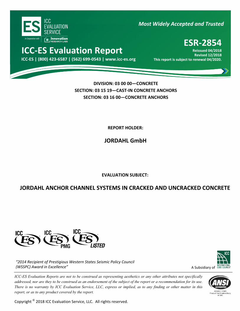
Where an anchor channel is located in a narrow member (ca2,max < ccr,V) with a thickness h < hcr,V (see Figure 4-17), the edge distance ca1 in Eq. (31), (33), (36) and (38) shall not exceed the value ca1,red determined in accordance with Eq. (39).
a ch ch
a red
c binc m
h hm2,max
1,
2max ;
2, .
2 (39)
where ca2,max is the largest of the edge distances perpendicular to the longitudinal axis of the channel.
Vua,y
ESR-2854 | Most Widely Accepted and Trusted Page 10 of 30
Influencing anchor Anchor under consideration
For this example, the value of ca1,red is obtained by moving the failure surface forward until it intersects the corner as shown.
FIGURE 4-17: EXAMPLE OF AN ANCHOR CHANNEL INFLUENCED BY TWO CORNERS AND MEMBER
THICKNESS (IN THIS EXAMPLE ca2,2 IS DECISIVE FOR THE DETERMINATION OF ca1,red)
For anchor channels with bch greater than 1.1 inches (28 mm) and hch greater than 0.6 inches (15 mm) arranged parallel to the edge and loaded by a shear load perpendicular to the edge and anchor reinforcement developed in accordance with ACI 318-11 Chapter 12 or ACI 318-14 Chapter 25 on both sides of the concrete surface, the design strength of the anchor reinforcement, Vca,y, shall be permitted to be used instead of the concrete breakout strength, Vcb,y, in determining Vn,y.
A strength reduction factor, , of 0.75 shall be used in the design of the anchor reinforcement. The strength of the anchor reinforcement assumed in design shall not exceed the value in accordance with Eq. (40). Only anchor reinforcement that complies with Figure 4-18 shall be assumed as effective.
The maximum strength of the anchor reinforcement Vca,y,max of a single anchor of an anchor channel shall be computed in accordance with Eq. (40).
ca y cb ya
V V lbc, ,max ,0.12
1
2.85,
(40)
ca y cb ya
V V Nc, ,max ,0.12
1
4.2,
where Vcb,y is determined in accordance with Eq. (30).
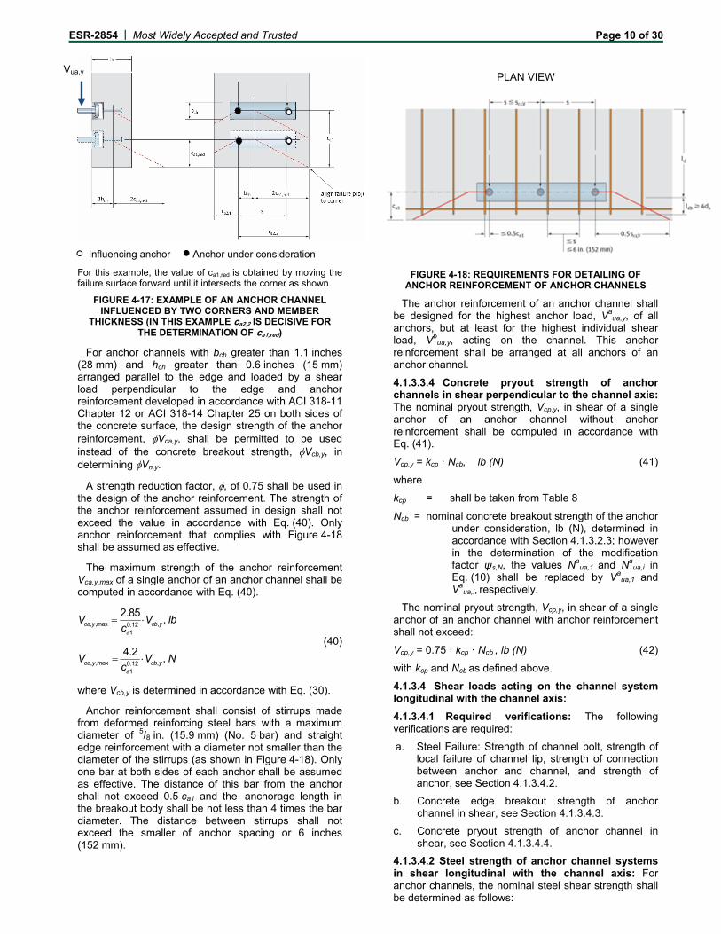
Anchor reinforcement shall consist of stirrups made from deformed reinforcing steel bars with a maximum diameter of 5/8 in. (15.9 mm) (No. 5 bar) and straight edge reinforcement with a diameter not smaller than the diameter of the stirrups (as shown in Figure 4-18). Only one bar at both sides of each anchor shall be assumed as effective. The distance of this bar from the anchor shall not exceed 0.5 ca1 and the anchorage length in the breakout body shall be not less than 4 times the bar diameter. The distance between stirrups shall not exceed the smaller of anchor spacing or 6 inches (152 mm).
PLAN VIEW
FIGURE 4-18: REQUIREMENTS FOR DETAILING OF
ANCHOR REINFORCEMENT OF ANCHOR CHANNELS
The anchor reinforcement of an anchor channel shall be designed for the highest anchor load, Va
ua,y, of all anchors, but at least for the highest individual shear load, Vb
ua,y, acting on the channel. This anchor reinforcement shall be arranged at all anchors of an anchor channel.
4.1.3.3.4 Concrete pryout strength of anchor channels in shear perpendicular to the channel axis: The nominal pryout strength, Vcp,y, in shear of a single anchor of an anchor channel without anchor reinforcement shall be computed in accordance with Eq. (41).
Vcp,y = kcp · Ncb, lb (N) (41)
where
kcp = shall be taken from Table 8
Ncb = nominal concrete breakout strength of the anchor under consideration, lb (N), determined in accordance with Section 4.1.3.2.3; however in the determination of the modification factor ψs,N, the values Na
ua,1 and Naua,i in
Eq. (10) shall be replaced by Vaua,1 and
Vaua,i, respectively.
The nominal pryout strength, Vcp,y, in shear of a single anchor of an anchor channel with anchor reinforcement shall not exceed:
Vcp,y = 0.75 · kcp · Ncb , lb (N) (42)
with kcp and Ncb as defined above.
4.1.3.4 Shear loads acting on the channel system longitudinal with the channel axis:
4.1.3.4.1 Required verifications: The following verifications are required:
a. Steel Failure: Strength of channel bolt, strength of local failure of channel lip, strength of connection between anchor and channel, and strength of anchor, see Section 4.1.3.4.2.
b. Concrete edge breakout strength of anchor channel in shear, see Section 4.1.3.4.3.
c. Concrete pryout strength of anchor channel in shear, see Section 4.1.3.4.4.
4.1.3.4.2 Steel strength of anchor channel systems in shear longitudinal with the channel axis: For anchor channels, the nominal steel shear strength shall be determined as follows:
Vua,y

ESR-2854 | Most Widely Accepted and Trusted Page 11 of 30
The nominal strength of a channel bolt in shear, Vss, shall be taken from Table 11 and 12 of this report.
If the load is not applied at the concrete surface but to a fixture secured to the channel bolt as a stand-off connection at a distance from the concrete surface (e.g. by double nuts), the nominal strength of a channel bolt in shear, Vss,M, shall be computed in accordance with Eq. (28).
The nominal strength of the channel lips to take up shear loads in direction of the longitudinal channel axis transmitted by a channel bolt, Vsl,x, shall be taken from Table 7 of this report.
The nominal strength of one anchor, Vsa,x, to take up shear loads perpendicular to the channel axis shall be taken from Table 7 of this report.
The nominal strength of the connection between one anchor and the anchor channel, Vsc,x, to take up shear loads longitudinal to the channel axis shall be taken from Table 7 of this report.
4.1.3.4.3 Concrete breakout strength of anchor channels in shear longitudinal with the channel axis: The nominal concrete breakout strength, Vcb,x, in shear in direction of the longitudinal channel axis of a single anchor of an anchor channel in cracked concrete shall be computed as follows:
a) For a shear force perpendicular to the edge, by Eq. (30). The basic concrete breakout strength in shear in direction of the longitudinal channel axis of a single anchor of an anchor channel in cracked concrete, Vb, shall be computed in accordance with Eq. (31).
b) For a shear force parallel to an edge, Vcb,x, shall be permitted to be 2 times the value of the shear force determined from Eq. (30) with the shear force assumed to act perpendicular to the edge.
4.1.3.4.4 Concrete pryout strength of anchor channels in shear longitudinal with the channel axis: The nominal pryout strength, Vcp,x, in shear of a single anchor of an anchor channel without anchor reinforcement shall be computed in accordance with Eq. (41).
The nominal pryout strength, Vcp,x, in shear of a single anchor of an anchor channel with anchor reinforcement shall not exceed Eq. (42).
4.1.3.5 Requirements for seismic design: Anchor channel systems shall be designed according to D.3.3.5 (ACI 318-05) or 17.2.3.5.3 (ACI 318-14).
The design of channel systems to resist tension loads in SDC C, D, E or F where D.3.3.4.2 (ACI 318-11) or 17.2.3.4.2 (ACI 318-14) applies shall satisfy the requirements of D.3.3.4.3. (b), (c) or (d) (ACI 318-11) or 17.2.3.4.3 (b), (c) or (d) (ACI 318-14), as applicable. The design of anchor channel systems to resist shear loads in SDC C, D, E or F where D.3.3.5.2 (ACI 318-11) or 17.2.3.5.2 (ACI 318-14) applies shall satisfy the requirements of D.3.3.5.3. (ACI 318-11) or 17.2.3.5.3 (ACI 318-14).
For anchor channel systems in SDC C, D, E or F, the design strengths given in Section 4.1.3.1 through Section 4.1.3.4 shall be taken as the corresponding seismic strengths Nn,seis, Vn,y,seis and Vn,x,seis.
4.1.3.6 Interaction of tensile and shear forces: If forces act in more than one direction, the combination of loads has to be verified.
Anchor channel systems subjected to combined axial and shear loads shall be designed to satisfy the following requirements by distinguishing between steel failure of the channel bolt, steel failure modes of the channel and concrete failure modes.
4.1.3.6.1 Steel failure of channel bolts under combined loads: For channel bolts, Eq. (43) shall be satisfied.
b bua ua
ss ss
N V
N V
2 2
1.0 (43)
with 2,
2
,b
yuab
xuab
ua VVV
where Nbua is the factored tension load, Vb
ua,y is the factor shear load in perpendicular direction, and Vb
ua,x is the factored shear load in longitudinal direction to the channel axis on the channel bolt under consideration.
This verification is not required in case of shear load with lever arm as Eq. (28) accounts for the interaction.
4.1.3.6.2 Steel failure modes of anchor channel systems under combined loads: For steel failure modes of anchor channel systems Eq. (44), Eq. (45) and Eq. (46) shall be satisfied.
a. For anchor and connection between anchor and channel:
α
sc,x
aua,x
sa,x
aua,x
α
sc,y
aua,y
sa,y
aua,y
α
sc
aua
sa
aua
V
V;
V
V
V
V;
V
V
N
N;
N
N
max1
maxmax
(44)
where
α = 2 for anchor channels with max (Vsa,y; Vsc,y) ≤ min (Nsa; Nsc)
α = 1 for anchor channels with max (Vsa,y; Vsc,y) > min (Nsa; Nsc)
It shall be permitted to assume reduced values for Vsa,y
and Vsc,y corresponding to the use of an exponent α = 2. In this case the reduced values for Vsa,y and Vsc,y shall also be used in Section 4.1.3.3.1a.
b. At the point of load application:
xsl
bxua
ysl
byua
sl
bua
V
V
V
V
N
N
,
,
,
, 0.1 (45)
xsl
bxua
ysl
byua
flexs
flexs
V
V
V
V
M
M
,
,
,
,
,
, 0.1 (46)
where
α = 2 for anchor channels with Vsl,y ≤ Ns,l
α = 1 for anchor channels with Vsl,y > Ns,l
4.1.3.6.3 Concrete failure modes of anchor channels under combined loads: For concrete failure modes, anchor channels shall be designed to satisfy the requirements in a) through d).

ESR-2854 | Most Widely Accepted and Trusted Page 12 of 30
a) If
, ,
, ,
0.2a a
ua y ua x
nc y nc x
V V
V V
then the full strength in tension shall be permitted:
anc uaN N
b) If 0.2aua ncN N then the full strength in shear shall be
permitted:
, ,
, ,
1.0a a
ua y ua x
nc y nc x
V V
V V
c) If
, ,
, ,
0.2a a
ua y ua x
nc y nc x
V V
V V and 0.2a
ua ncN N
then Eq. (47) applies
, ,
, ,
1.2a aa
ua y ua xua
nc nc y nc x
V VN
N V V
(47)
d) Alternatively, instead of satisfying the requirements in a) through c), the interaction Eq. (48) shall be satisfied:
5 553 33
, ,
, ,
1.0a aa
ua y ua xua
nc nc y nc x
V VN
N V V (48)
4.1.4 Minimum Member Thickness, Anchor Spacing, and Edge Distance: Anchor channels shall satisfy the requirements for edge distance, spacing, and member thickness.
The minimum edge distance, minimum and maximum anchor spacing and minimum member thickness shall be taken from Table 1 of this report. The critical edge distance, cac, shall be taken from Table 5 of this report.
Allowable Stress Design: 4.2
4.2.1 General: Strength design values determined in accordance with ACI 318 (-05, -08, -11) Appendix D or ACI 318-14 Chapter 17, as applicable, with amendments in Section 4.1 of this report, may be converted to values suitable for use with allowable stress design (ASD) load combinations. Such guidance of conversions shall be in accordance with the following:
For anchor channel systems designed using load combinations in accordance with IBC Section 1605.3 (Allowable Stress Design), allowable loads shall be established using Eq. (48), Eq. (49), Eq. (50) and Eq. (51).
,n
allowable ASDASD
NT
(48)
,, ,
n xx allowable ASD
ASD
VV (49)
n yy allowable ASD
ASD
VV ,
, ,
(50)
s flexs flex allowable ASD
ASD
MM ,
, , , (51)
where
Tallowable,ASD = Allowable tension load lb (N)
Vx,allowable,ASD = Allowable shear load longitudinal with the channel axis, lb (N)
Vy,allowable,ASD = Allowable shear load perpendicular to the channel axis, lb (N)
Ms,flex,allowable,ASD = Allowable bending moment due to tension loads lb-in (Nm)
ΦNn = Lowest design strength of an anchor, channel bolt, or anchor channel in tension for controlling failure mode as determined in accordance with ACI 318 (-05, -08, -11) Appendix D or ACI 318-14 Chapter 17 as applicable with amendments in Section 4.1 of this report, lb (N).
Vn,x = Lowest design strength of an anchor, channel bolt, or anchor channel in shear longitudinal with the channel axis for controlling failure mode as determined in accordance with ACI 318 (-05, -08, -11) Appendix D or ACI 318-14 Chapter 17 as applicable with amendments in Section 4.1 of this report, lb (N).
Vn,y = Lowest design strength of an anchor, channel bolt, or anchor channel in shear perpendicular to the channel axis for controlling failure mode as determined in accordance with ACI 318 (-05, -08, -11) Appendix D or ACI 318-14 Chapter 17 as applicable with amendments in Section 4.1 of this report, lb (N).
αASD = Conversion factor calculated as a weighted average of the load factors for the controlling load combination. In addition, αASD shall include all applicable factors to account for non-ductile failure modes and required overstrength.
4.2.2 Interaction of tensile and shear forces: Interaction shall be calculated in accordance with Section 4.1.3.4 and amendments in Section 4.1 of this report.
Nua, Vua,x, Vua,y and Mu,flex shall be replaced by the unfactored loads Ta, Va
x, Vay and Ma. The design
strengths Nn, Vn,x, Vn,y and Ms,flex shall be replaced by the allowable loads Tallowable,ASD, Vx,allowable,ASD, Vy,allowable,ASD and Ms,flex,allowable,ASD.
where
Ta = unfactored tension load applied to an anchor channel system, lb (N)
Ma = unfactored bending moment on anchor channel due to tension loads (calculation according to Section 4.1.2.2, lb-in (Nm)
Vax = unfactored shear load applied to an anchor
channel system longitudinal with the channel axis, lb (N)
Vay = unfactored shear load applied to an anchor
channel system perpendicular to the channel axis, lb (N)
Installation: 4.3
Installation parameters are provided in Table 1 of this report. Anchor channel location must comply with this report and the plans and specifications approved by the code official. Installation of the anchor channel systems must conform to the manufacturer’s printed installation instructions (MPII) included with the product, as provided in Figure 8-4. Minimum end distance for cutting anchor channels shall be in accordance with the minimum end spacing, xmin, listed in Table 1 of this report.
Channel installation in formwork includes the following steps according to Figure 8-4:

ESR-2854 | Most Widely Accepted and Trusted Page 13 of 30
1. Install the channel surface flush and fix the channel securely to the formwork or to the reinforcement.
1a. Fixing to steel formwork: With JORDAHL channel bolts and nuts, with rivets, clamps, or magnetic fixings, or
1b. Fixing to timber formwork: With nails through the pre-punched holes in the back of the channels or with staples, or
1c. Fixing to the anchor channels at the top: To timber battens on the side formwork (e.g. with JORDAHL channel bolts); or fixing from above directly to the reinforcement; or fixing to a rebar by wire tying.
2. Pouring concrete and regular compacting of concrete. Compact the concrete properly around the channel and the anchors, around the sidefaces to the formwork (2a), in soffits (2b), and into top surfaces of concrete up stands (2c).
3. After hardening of concrete, remove the channel foam infill. Clean the channel on the outside after removing the formwork. Clean the foam infill with the claw of a hammer or a hook (3a), or clean the polyethylene-foam infill in one piece by hand or with the help of a screwdriver (3b).
4. Fastening the JORDAHL channel bolt to the anchor channel for (a) the general application (fixture in contact with concrete):
i. Insert the Jordahl channel bolt into the channel slot at any point along the channel length.
ii. Turn the channel bolt 90 degrees clockwise and the head of the bolt will lock into position.
iii. Do not mount the channel bolt at the end of the channel within the end distance xmin according to Table 1.
iv. Install the fixture. Use a washer under the nut.
v. Check the correct fit of the JORDAHL channel bolt. The groove on the shank end of the channel bolt must be perpendicular to the channel longitudinal axis.
vi. Tighten the nuts by a calibrated torque wrench to the setting torque according to Table 13 for general installation. The setting torque shall not be exceeded.
Fastening the JORDAHL channel bolt to the anchor channel for (b) steel-to-steel contact (fixture in contact with the anchor channel only):
i. Insert the Jordahl channel bolt into the channel slot at any point along the channel length.
ii. Turn the channel bolt 90 degrees clockwise and the head of the bolt will lock into position.
iii. Do not mount the channel bolt at the end of the channel within the end distance xmin according to Table 1.
iv. Use washers between channel and fixture to avoid bearing of the fixture against the concrete.
v. Install the fixture. Use a washer under the nut.
vi. Check the correct fit of the JORDAHL channel bolt. The groove on the shank end of the channel bolt must be perpendicular to the channel longitudinal axis.
vii. Tighten the nuts by a calibrated torque wrench to the setting torque according to Table 14 for steel-to-steel contact. The setting torque shall not be exceeded.
Special Inspection: 4.4
Periodic special inspection shall be performed as required in accordance with Section 1705.1.1 and Table 1705.3 of the 2015 and 2012 IBC, Section 1704.15 of the 2009 IBC or Section 1704.13 of the 2006 IBC and in accordance with this report.
4.4.1 Inspection requirements: Prior to concrete placement, the special inspector shall inspect the placement of anchor channels in the formwork to verify anchor channel type, channel size, anchor type, number of anchors, anchor size, and length of anchors, as well as anchor channel location, position, orientation, and edge distance in accordance with the construction documents. The special inspector shall also verify that anchor channels are secured within the formwork in accordance with the manufacturer’s printed installation instructions (MPII).
Following placement of concrete and form removal, the special inspector shall verify that the concrete around the anchor channel is without significant visual defects, that the anchor channel is flush with the concrete surface, and that the channel interior is free of concrete, laitance, or other obstructions. When anchor channels are not flush with the concrete surface, the special inspector shall verify that appropriate sized shims are provided in accordance with the MPII. Following the installation of attachments to the anchor channel, the special inspector shall verify that the specified system hardware, such as T-headed channel bolts and washers, have been used and positioned correctly, and the installation torque has been applied to the channel bolts in accordance with the installation instructions (MPII). For the JTA channel systems (non-serrated), the special inspector shall confirm with the engineer of record that the attachments do not produce gravity, wind, and/or seismic loading parallel to the longitudinal axis of the channel (see Figure 2-1).
The special inspector shall be present for the installations of attachments to each type and size of anchor channel.
Where they exceed the requirements stated here, the special inspector shall adhere to the special inspection requirements provided in the statement of special inspections as prepared by the registered design professional in responsible charge.
4.4.2 Proof loading program: Where required by the registered design professional in responsible charge, a program for on-site proof loading (proof loading program) to be conducted as part of the special inspection shall include at a minimum the following information:
1. Frequency and location of proof loading based on channel size and length;
2. Proof loads specified by channel profile size and channel bolt;
3. Acceptable displacements at proof load;
4. Remedial action in the event of failure to achieve proof load or excessive displacement.

ESR-2854 | Most Widely Accepted and Trusted Page 14 of 30
CONDITIONS OF USE 5.0
The Jordahl JTA and JXA anchor channel systems described in this report are suitable alternatives to what is specified in the codes listed in Section 1.0 of this report, subject to the following conditions:
The Jordahl JTA AND JXA anchor channel 5.1systems must be installed in accordance with the manufacturer’s printed installation instructions (MPII) and this report as depicted in Figure 8-1, Figure 8-4 and Table 1. In case of a conflict, this report governs.
The Jordahl JTA (non-serrated) anchor channel 5.2systems are used to resist static, wind, and seismic (IBC Seismic Design Categories A and B) tension loads (Nua) and shear loads perpendicular to the longitudinal channel axis (Vua,y), or any combination of these loads applied at any location between the outermost anchors of the anchor channel in accordance with Figure 2-1 of this report.
The Jordahl JXA serrated (toothed) anchor channel systems are used to resist static, wind, and seismic (IBC Seismic Design Categories A through F) tension loads (Nua), shear loads perpendicular to the longitudinal channel axis (Vua,y), and shear loads longitudinal with the channel axis or any combination of these loads applied at any location between the outermost anchors of the anchor channel in accordance with Figure 2-1 of this report.
The Jordahl JTA and JXA anchor channel systems 5.3must be limited to the use in cracked or uncracked normal weight concrete having a specified compressive strength, f'c, of 2,500 psi to 10,000 psi (17.2 MPa to 69.0 MPa) [minimum of 24 MPa is required under ADIBC Appendix L, Section 5.1.1].
The use of the Jordahl JTA and JXA anchor 5.4channel systems in lightweight concrete is beyond the scope of this report.
Strength design values must be established in 5.5accordance with Section 4.1 of this report.
Allowable stress design values are established in 5.6Section 4.2 of this report.
Minimum and maximum anchor spacing and 5.7minimum edge distance as well as minimum member thickness must comply with the values given in Table 1 of this report.
Channel bolt installation must include the use of a 5.8plate washer or fixture and proper tightening torque. Apply the installation torque Tinst to the channel bolt with a calibrated torque wrench. Do not exceed the value Tinst in the table in Figure 8-4.
Prior to anchor channel system installation, 5.9calculations and details demonstrating compliance with this report must be submitted to the code official. The calculations and details must be prepared by a registered design professional where required by the statutes of the jurisdiction in which the project is to be constructed.
Where not otherwise prohibited in the code, 5.10Jordahl JTA and JXA anchor channel systems are permitted for use with fire-resistance-rated construction provided that at least one of the following conditions is fulfilled:
Anchor channel systems are used to resist wind or seismic forces only.
Anchor channel systems that support a fire-resistance-rated envelope or a fire-resistance-rated membrane are protected by approved fire-resistance-rated materials, or have been evaluated for resistance to fire exposure in accordance with recognized standards.
Anchor channel systems are used to support nonstructural elements.
Since an acceptance criteria for evaluating data to 5.11determine the performance of anchor channel systems subjected to fatigue or shock loading is unavailable at this time, the use of these anchor channel systems under such conditions is beyond the scope of this report.
Use of hot-dipped galvanized carbon steel anchor 5.12channel systems is permitted for exterior exposure or damp environments. In case anchor channels are cut after applying the zinc coating, only use in dry internal conditions is permitted.
Steel anchoring materials in contact with 5.13preservative-treated and fire-retardant-treated wood shall be of zinc-coated carbon steel. The minimum coating weights for zinc-coated steel shall comply with ASTM A153.
Special inspection must be provided in accordance 5.14with Section 4.4 of this report.
Jordahl JTA and JXA anchor channel systems are 5.15produced under an approved quality-control program with inspections performed by ICC-ES.
EVIDENCE SUBMITTED 6.0
Data in accordance with ICC-ES Acceptance 6.1Criteria for Anchor Channels in Concrete Elements (AC232), dated June 2018.
Quality-control documentation. 6.2
IDENTIFICATION 7.0
The anchor channels are identified by the 7.1manufacturer’s name, anchor channel type and size and material type (e.g. Jordahl W 53/34-A4), as well as the production lot number. Additionally, the profile designation in accordance with Table 17 of this report is visible on the anchor head in the channel after installation of the anchor channel and placement of the concrete. The evaluation report number (ESR-2854) is also listed on the product packaging.
Channel bolts are identified by packaging labeled 7.2with the manufacturer’s name, bolt type, bolt diameter and length, bolt grade, corrosion protection type (e.g. JB M16x50 8.8 H.D.G.), evaluation report number (ESR-2854) and batch number. The manufacturer, bolt type, and bolt grade type is embossed into the channel bolt head.
7.3 The report holder’s contact information is as follows:
JORDAHL GMBH 51 NOBELSTRASSE BERLIN 12057 GERMANY +49 30 68283 02 www.deconusa.com www.jordahl.de

ESR-2854 | Most Widely Accepted and Trusted Page 15 of 30
NOTATIONS 8.0
Equations are provided in units of inches and pounds. For convenience, SI (metric) units are provided in parentheses where appropriate. Unless otherwise noted, values in SI units shall be not used in equations without conversion to units of inches and pounds.
bch width of channel, as shown in Figure 8-2, inch (mm)
ca edge distance of anchor channel, measured from edge of concrete member to axis of the nearest anchor as shown in Figure 8-1, in. (mm)
ca1 edge distance of anchor channel in direction 1 as shown in Figure 4-4, in. (mm)
c'a1 net distance between edge of the concrete member and the anchor channel: c'a1 = ca1 – bch/2 in. (mm)
ca1,red reduced edge distance of the anchor channel, as referenced in Eq. (39)
ca2 edge distance of anchor channel in direction 2 as shown in Figure 4-4, in. (mm)
ca,max maximum edge distance of anchor channel, in. (mm)
ca,min minimum edge distance of anchor channel, in. (mm)
cac edge distance required to develop full concrete capacity in absence of reinforcement to control splitting, in. (mm)
ccr edge distance required to develop full concrete capacity in absence of anchor reinforcement, in. (mm)
ccr,N critical edge distance for anchor channel for tension loading for concrete breakout, in. (mm)
ccr,Nb critical edge distance for anchor channel for tension loading, concrete blow out, in. (mm)
ccr,V critical edge distance for anchor channel for shear loading, concrete edge breakout, in. (mm)
d1 diameter of head of round anchor, in. (mm)
d2 shaft diameter of round anchor, in. (mm)
df diameter of hole in the fixture, in. (mm)
da diameter of anchor reinforcement, in. (mm)
ds diameter of channel bolt, in. (mm)
e1 distance between shear load and concrete surface, in. (mm)
es distance between the axis of the shear load and the axis of the anchor reinforcement resisting the shear load, in. (mm)
f distance between anchor head and surface of the concrete, in. (mm)
f′c specified concrete compressive strength, psi (MPa)
futa specified ultimate tensile strength of anchor, psi (MPa)
futc specified ultimate tensile strength of channel, psi (MPa)
futb specified ultimate tensile strength of channel bolt, psi (MPa)
fy specified yield tensile strength of steel, psi (MPa)
fya specified yield strength of anchor, psi (MPa)
fyc specified yield strength of channel, psi (MPa)
fyb specified yield strength of channel bolt, psi (MPa)
h thickness of concrete member, as shown in Figure 8-1, inch (mm)
hch height of channel, as shown in Figure 8-1, in. (mm)
hcr,V critical member thickness, in. (mm)
hef effective embedment depth, as shown in Figure 8-1, in. (mm)
hef,red reduced effective embedment depth, as referenced in Eq. (9), in. (mm)
hnom nominal embedment depth, as shown in Figure 8-1, in. (mm)
k load distribution factor, as referenced in Eq. (1)
kcp pryout factor
ℓA nominal embedment depth, minus channel height, in. (mm)
ℓ lever arm of the shear force acting on the channel bolt, in. (mm)
ℓdh development length in tension of deformed bar or deformed wire with a standard hook, measured from critical section to outside end of hook, in. (mm)

ESR-2854 | Most Widely Accepted and Trusted Page 16 of 30
ℓi influence length of an external load Nua along an anchor channel, in. (mm)
s spacing of anchors in direction of longitudinal axis of channel, in. (mm)
schb center-to-center distance between channel bolts in direction of longitudinal axis of channel, in. (mm)
scr anchor spacing required to develop full concrete capacity in absence of anchor reinforcement, in. (mm)
scr,N critical anchor spacing for tension loading, concrete breakout, in. (mm)
smax maximum spacing between anchor elements in anchor channels, in. (mm)
smin minimum spacing between anchor elements in anchor channels, in. (mm)
scr,Nb critical anchor spacing for tension loading, concrete blow-out, in. (mm)
scr,V critical anchor spacing for shear loading, concrete edge breakout, in. (mm)
th thickness of head portion of headed anchor, in. (mm)
x distance between end of channel and nearest anchor, in. (mm)
z internal lever arm of the concrete member, in. (mm)
Abrg bearing area of anchor head, in.2 (mm2)
Ai ordinate at the position of the anchor i, as illustrated in Figure 4-1, in. (mm)
Ase,N effective cross-sectional area of anchor or channel bolt in tension, in.2, (mm²)
Ase,V effective cross-sectional area of channel bolt in shear (mm²)
Iy moment of inertia of the channel about principal y-axis, in.4 (mm4)
M1 bending moment on fixture around axis in direction 1, lb-in (Nm)
M2 bending moment on fixture around axis in direction 2, lb-in (Nm)
Ms,flex nominal flexural strength of the anchor channel, lb-in (Nm)
Mss flexural strength of the channel bolt, lb-in (Nm)
ssM 0 nominal flexural strength of the channel bolt, lb-in (Nm)
Mu,flex bending moment on the channel due to tension loads, lb-in (Nm)
Nb basic concrete breakout strength of a single anchor in tension, lb (N)
Nca nominal strength of anchor reinforcement to take up tension loads, lb (N)
Ncb concrete breakout strength of a single anchor of anchor channel in tension, lb (N)
Nn lowest nominal tension strength from all appropriate failure modes under tension, lb (N)
Np pullout strength of a single anchor of an anchor channel in tension, lb (N)
Npn nominal pullout strength of a single anchor of an anchor channel in tension, lb (N)
Nnc nominal tension strength of one anchor from all concrete failure modes (lowest value of Ncb [anchor channels without anchor reinforcement to take up tension loads] or Nca [anchor channels with anchor reinforcement to take up tension loads], Npn, and Nsb)
Nns nominal steel strength of anchor channel loaded in tension (lowest value of Nsa, Nsc and Nsl), lb (N)
Nns,a nominal tension strength for steel failure of anchor or connection between anchor and channel (lowest value of Nsa and Nsc)
Nsa nominal tensile steel strength of a single anchor, lb (N)
Nsb nominal concrete side-face blowout strength, lb (N)
sbN0 basic nominal concrete side-face blowout strength, lb (N)
Nsc nominal tensile steel strength of the connection between channel and anchor, lb (N)
Nsl nominal tensile steel strength of the local bending of the channel lips, lb (N)
Nss nominal tensile strength of a channel bolt, lb (N)
auaN factored tension load on a single anchor of the anchor channel, lb (N)
aua iN ,
factored tension load on anchor i of the anchor channel, lb (N)
buaN factored tension load on a channel bolt, lb (N)
Nua,re factored tension load acting on the anchor reinforcement, lb (N)
Tallowable,ASD allowable tension load for use in allowable stress design environments, lb (N)
Tinst installation torque moment given in installation instructions (MPII), lb-in. (N-m)

ESR-2854 | Most Widely Accepted and Trusted Page 17 of 30
Vx,allowable,ASD allowable shear load longitudinal with the channel axis for use in allowable stress design environments, lb (N)
Vy,allowable,ASD allowable shear load perpendicular to the channel axis for use in allowable stress design environments, lb (N)
Vb basic concrete breakout strength in shear of a single anchor, lb (N)
Vca,x nominal strength of the anchor reinforcement of one anchor to take up shear loads longitudinal with the channel axis, lb (N)
Vca,y nominal strength of the anchor reinforcement of one anchor to take up shear loads perpendicular to the channel axis, lb (N)
Vca,y,max maximum value of Vca,y of one anchor to be used in design, lb (N)
Vcb,x nominal concrete breakout strength in shear longitudinal with the channel axis of an anchor channel, lb (N)
Vcb,y nominal concrete breakout strength in shear perpendicular to the channel axis of an anchor channel, lb (N)
Vcp nominal pry-out strength of a single anchor (Vcp,x = Vcp,y), lb (N)
Vcp,x nominal pry-out strength longitudinal with the channel axis of a single anchor, lb (N)
Vcp,y nominal pry-out strength perpendicular to the channel axis of a single anchor, lb (N)
Vn,x lowest nominal steel strength from all appropriate failure modes under shear longitudinal with the channel axis, lb (N)
Vn,y lowest nominal steel strength from all appropriate failure modes under shear perpendicular to the channel axis, lb (N)
Vnc nominal shear strength of one anchor from all concrete failure modes (lowest value of Vcb [anchor channels with anchor reinforcement to take up shear loads] or Vca [anchor channels with anchor reinforcement to take up shear loads] and Vcp)
Vns Nominal steel strength of anchor channel loaded in shear (lowest value of Vsa, Vsc, and Vsl)
Vns,a nominal shear strength for steel failure of anchor or connection between anchor and channel (lowest value of Vsa and Vsc)
Vsa,x nominal shear steel strength longitudinal with the channel axis of a single anchor, lb (N)
Vsa,y nominal shear steel strength perpendicular to the channel axis of a single anchor, lb (N)
Vsa,x,seis nominal seismic shear steel strength longitudinal with the channel axis of a single anchor, lb (N)
Vsa,y,seis nominal seismic shear steel strength perpendicular to the channel axis of a single anchor, lb (N)
Vsc,x nominal shear strength longitudinal with the channel axis of connection between one anchor and the anchor channel, lb (N)
Vsc,y nominal shear strength perpendicular to the channel axis of connection between one anchor and the anchor channel, lb (N)
Vsc,x,seis nominal seismic shear strength longitudinal with the channel axis of connection between one anchor bolt and the anchor channel, lb (N)
Vsc,y,seis nominal seismic shear strength perpendicular to the channel axis of connection between one anchor bolt and the anchor channel, lb (N)
Vsl,x nominal shear steel strength longitudinal with the channel axis of the local bending of the channel lips, lb (N)
Vsl,y nominal shear steel strength perpendicular to the channel axis of the local bending of the channel lips, lb (N)
Vsl,x,seis nominal seismic shear steel strength longitudinal with the channel axis of the local bending of the channel lips, lb (N)
Vsl,y,seis nominal seismic shear steel strength perpendicular to the channel axis of the local bending of the channel lips, lb (N)
Vss nominal strength of channel bolt in shear, lb (N)
Vss,M nominal strength of channel bolt in case of shear with lever arm, lb (N)
uaV factored shear load on anchor channel, lb (N)
Vua,x factored shear load on anchor channel longitudinal with the channel axis, lb (N)
ua yV , factored shear load on anchor channel perpendicular to the channel axis, lb (N)
auaV factored shear load on a single anchor of the anchor channel, lb (N)
,a
ua xV factored shear load on a single anchor of the anchor channel longitudinal with the channel axis, lb (N)
aua yV ,
factored shear load on a single anchor of the anchor channel perpendicular to the channel axis, lb (N)

ESR-2854 | Most Widely Accepted and Trusted Page 18 of 30
aua iV ,
factored shear load on anchor i of the anchor channel, lb (N)
, ,a
ua x iV factored shear load on anchor i of the anchor channel in longitudinal channel axis, lb (N)
aua y iV , ,
factored shear load on anchor i of the anchor channel perpendicular to the channel axis, lb (N)
buaV factored shear load on a channel bolt, lb (N)
,b
ua xV factored shear load on a channel bolt in longitudinal channel axis, lb (N)
bua yV ,
factored shear load on a channel bolt perpendicular to the channel axis, lb (N)
α exponent of interaction equation (see Section 4.1.3.4)
αASD conversion factor for allowable stress design (see Section 4.2)
αch,N factor to account for the influence of channel size on concrete breakout strength in tension
αM factor to account for the influence of restraint of fixture on the flexural strength of the channel bolt
αch,V factor to account for the influence of channel size and anchor diameter on concrete edge breakout strength in shear (lb0.5/in)0.33 (N0.5/mm0.33)
β1 exponent in Eq. (37) to account for the influence of the member depth on the concrete edge breakout strength in accordance with Table 8
ψc,N modification factor to account for influence of cracked or uncracked concrete on concrete breakout strength
ψc,Nb modification factor to account for influence of cracked or uncracked concrete on concrete blowout strength
ψc,V modification factor to account for influence of cracked or uncracked concrete for concrete edge breakout strength
ψco,N modification factor for corner effects on concrete breakout strength for anchors loaded in tension
ψco,Nb modification factor for corner effects on concrete blowout strength for anchors loaded in tension
ψco,V modification factor for corner effects on concrete edge breakout strength for anchor channels loaded in shear
ψcp,N modification factor for anchor channels to control splitting
ψed,N modification factor for edge effect on concrete breakout strength for anchors loaded in tension
ψg,Nb modification factor to account for influence of bearing area of neighboring anchors on concrete blowout strength for anchors loaded in tension
ψh,Nb modification factor to account for influence of member thickness on concrete blowout strength for anchors loaded in tension
ψh,V modification factor to account for influence of member thickness on concrete edge breakout strength for anchors channels loaded in shear
ψs,N modification factor to account for influence of location and loading of neighboring anchors on concrete breakout strength for anchor channels loaded in tension
ψs,Nb modification factor to account for influence of location and loading of neighboring anchors on concrete blowout strength for anchor channels loaded in tension
ψs,V modification factor to account for influence of location and loading of neighboring anchors on concrete edge breakout strength for anchor channels loaded in shear

ESR-2854 | Most Widely Accepted and Trusted Page 19 of 30
FIGURE 8-1—INSTALLATION PARAMETERS FOR JORDAHL JTA AND JXA ANCHOR CHANNELS
FIGURE 8-2—ANCHOR CONNECTION TYPES FIGURE 8-3—CHANNEL BOLTS
Channel
Toothed-T-Bolt
e.g. JXB M16 x 60
A) Anchor channel hot-rolled profile
B) Anchor channel cold-formed profile
xmin
d2
Anchor (also possible as weld-on round anchor for K-Series)
Channel e.g.
JXA-W 53/34
Washer
Hexagon nut
Anchor
C) Anchor channel hot-rolled toothed
Toothed
channel bolts

ESR-2854 | Most Widely Accepted and Trusted Page 20 of 30
TABLE 1—INSTALLATION PARAMETERS FOR JORDAHL ANCHOR CHANNELS
Parameter Symbol Units JTA JXA
K 28/15 K 38/17 W 40/22 W 50/30 W 53/34 W 55/422 W 72/482 W 38/232 W 53/342
Channel height hch in 0.60 0.69 0.91 1.18 1.32 1.65 1.91 0.91 1.34
(mm) (15.25) (17.5) (23) (30) (33.5) (42) (48.5) (23) (34)
Channel width bch in 1.10 1.50 1.56 1.93 2.07 2.15 2.83 1.50 2.07
(mm) (28) (38) (39.5) (49) (52.5) (54.5) (72) (38) (52.5) Moment of inertia, carbon and stainless steel
Iy in4 0.010 0.021 0.0471 0.125 0.224 0.450 0.840 0.051 0.223
(mm4) (4060) (8547) (19703)1 (51904) (93262) (187464) (349721) (21100) (92600)
Minimum anchor spacing
smin in 1.97 1.97 1.97 1.97 3.15 3.15 3.15 1.97 3.15
(mm) (50) (50) (50) (50) (80) (80) (80) (50) (80) Maximum anchor spacing
smax in 7.87 7.87 9.84 9.84 9.84 11.81 15.75 9.84 9.84
(mm) (200) (200) (250) (250) (250) (300) (400) (250) (250) Effective embedment depth
hef in 1.77 2.99 3.11 3.70 6.10 6.89 7.05 3.74 6.10
(mm) (45) (76) (79) (94) (155) (175) (179) (95) (155)
Nominal embedment depth
hnom in 1.97 3.15 3.54 3.94 6.5 7.48 7.68 3.94 6.5
(mm) (50) (80) (90) (100) (165) (190) (195) (100) (165)
Thickness of the anchor head
th in 0.08 0.12 0.08 0.12 0.12 0.14 0.14 0.12 0.12
(mm) (2) (3) (2) (3) (3) (3.5) (3.5) (3) (3) Minimum edge distance
ca,min in 1.60 2.00 2.00 3.00 4.00 4.00 6.00 3.00 4.00
(mm) (41) (51) (51) (76) (102) (102) (152) (76) (102) Minimum end spacing
xmin in 0.98 0.98 0.98 0.98 1.38 1.38 1.38 0.98 1.38
(mm) (25) (25) (25) (25) (35) (35) (35) (25) (35) Anchor shaft diameter
d2 in 0.28 0.35 0.33 0.35 0.45 0.61 0.61 0.39 0.45
(mm) (7.0) (9) (8.5) (9) (11.5) (15.5) (15.5) (10) (11.5)
Head diameter d1 in 0.47 0.67 0.59 0.69 0.93 1.10 1.22 0.77 0.93
(mm) (12.0) (17.0) (15.0) (17.5) (23.5) (28.0) (31.0) (19.5) (23.5) Net bearing area of the anchor head
Abrg in2 0.12 0.25 0.19 0.27 0.51 0.66 0.88 0.34 0.51
(mm2) (74.6) (163.4) (120.0) (176.9) (329.9) (427.1) (566.1) (220.0) (329.9) Minimum concrete member thickness
hmin in
2.60 (66)
3.78 (96)
4.17 (106)
4.57 (116)
7.13 (181)
8.11 (206)
8.31 (211)
4.72 (120)
7.48 (190) (mm)
1 Iy in stainless steel = 0.05 in4 (19759 mm4)
2Available only in carbon steel
TABLE 2—JORDAHL ANCHOR PROFILE AND CORRESPONDING CHANNEL BOLT COMBINATIONS
Parameter Symbol Units JTA JXA
K 28/15 K 38/17 W 40/22 W 50/30 W 53/34 W 55/42 W 72/48 W 38/23 W 53/34
Bolt Type - - JD1 JH1 JC2 JB2 JB2 JB/JE2,3 JA2 JXH4 JXB4
Diameter ds (mm)
6 - - - - - - - -
8 - - - - - - - -
10 10 10 10 10 10 - - -
12 12 12 12 12 12 - 12 -
- 16 16 16 16 16 - 16 16
- - - 20 20 20 20 - 20
- - - - - 24 24 - -
- - - - - - 27 - -
- - - - - - 30 - -
1Hammer-head channel bolts 2Hooked-head channel bolts 3M10 through M20 JB; M24 JE 4Toothed channel bolts

ESR-2854 | Most Widely Accepted and Trusted Page 21 of 30
TABLE 3—STEEL TENSION STRENGTH DESIGN INFORMATION, JORDAHL JTA ANCHOR CHANNELS3
Parameter Symbol UnitsJTA
K 28/15 K 38/17 W 40/22 W 50/30 W 53/34 W 55/422 W 72/482
Nominal tensile steel strength for local failure of channel lips
Nsl lb 2025 4045 6745 8095 14615 21355 24730
(kN) (9) (18) (30) (36) (65) (95) (110) Strength reduction factor for local failure of channel lips1 - 0.75 (0.80)
Nominal tensile steel strength of a single anchor
Nsa lb 2025 4045 4495 6970 12365 17985 22480
(kN) (9) (18) (20) (31) (55) (80) (100) Strength reduction factor for anchor failure1 - 0.75 (0.80)
Nominal tensile steel strength of connection between anchor and channel
Nsc lb 2025 4045 4495 6970 12365 17985 22480
(kN) (9) (18) (20) (31) (55) (80) (100) Strength reduction factor for failure of connection between anchor and channel1 - 0.75 (0.80)
Nominal bending strength of the anchor channel, carbon steel
Ms,flex lb-in 2805 5135 10770 17860 28460 59130 80540 (Nm) (317) (580) (1217) (2018) (3215) (6681) (9100)
Nominal bending strength of the anchor channel, stainless steel
Ms,flex lb-in 2865 5245 12155 20095 32015 - - (Nm) (324) (593) (1373) (2270) (3617) - -
Strength reduction factor for bending failure1 - 0.85 (0.90)
1The tabulated value of applies when the load combinations of Section 1605.2 of the IBC, ACI 318-14 Section 5.3 or ACI 318-11 Section 9.2 are used. If the load combinations of ACI 318-11 Appendix C are used, the appropriate value of in parentheses must be used. 2Available only in carbon steel. 3Values valid for carbon steel and stainless steel, unless noted otherwise.
TABLE 4—STEEL TENSION STRENGTH DESIGN INFORMATION, JORDAHL JXA ANCHOR CHANNELS
Parameter Symbol Units JXA²
W 38/23 W53/34
Nominal tensile steel strength for local failure of channel lips
Nsl lb 8329 17683
(kN) (37.0) (78.7)
Nominal tensile steel strength for local failure of channel lips for seismic design
Nsl,seis lb
(kN) 8329 17683 (37.0) (78.7)
Strength reduction factor for local failure of channel lips1 1 - 0.75 (0.80)
Nominal tensile steel strength of a single anchor
Nsa lb 7063 12843
(kN) (31.4) (57.1)
Nominal tensile steel strength of a single anchor for seismic design
Nsa,seis lb
(kN) 7063 12843 (31.4) (57.1)
Strength reduction factor for anchor failure1 1 - 0.75 (0.80)
Nominal tensile steel strength of connection between anchor and channel
Nsc lb 8329 17683
(kN) (37.0) (78.7) Nominal tensile steel strength of connection between anchor and channel for seismic design
Nsc lb
(kN)
8329 17683
(37.0) (78.7)
Strength reduction factor for failure of connection between anchor and channel1 1 - 0.75 (0.80)
Nominal bending strength of the anchor channel
Ms,flex lb-in 14139 36746 (Nm) (1597) (4152)
Nominal bending strength of the anchor channel for seismic design
Ms,flex,seis lb-in 14139 36746 (Nm) (1597) (4152)
Strength reduction factor for bending failure1 1 - 0.85 (0.90) 1The tabulated value of applies when the load combinations of Section 1605.2 of the IBC, ACI 318-14 Section 5.3 or ACI 318-11 Section 9.2 are used. If the load combinations of ACI 318-11 Appendix C are used, the appropriate value of in parentheses must be used. 2Available only in carbon steel.

ESR-2854 | Most Widely Accepted and Trusted Page 22 of 30
TABLE 5—CONCRETE TENSION STRENGTH DESIGN INFORMATION, JORDAHL JTA AND JXA ANCHOR CHANNELS
Parameter Symbol Units JTA JXA
K 28/15 K 38/17 W 40/22 W 50/30 W 53/34 W 55/42 W 72/48 W 38/23 W 53/34
Effective embedment depth
hef in 1.77 2.99 3.11 3.70 6.10 6.89 7.05 3.74 6.10
(mm) (45) (76) (79) (94) (155) (175) (179) (95) (155)
Edge distance required to develop full concrete capacity in absence of anchor reinforcement
cac in 5.31 8.97 9.33 11.1 18.3 20.67 21.15 11.2 18.3
(mm) (135) (228) (237) (282) (465) (525) (537) (285) (465)
Pullout Strength1 Np lb 2293 4990 3665 5420 10095 13060 17310 6723 10095
(kN) (10.2) (22.2) (16.3) (24.1) (44.9) (58.1) (77) (29.9) (44.9)
Strength reduction factor for tension, concrete failure modes2
- 0.70
1Pullout strengths based on cracked concrete, f’c = 2,500 psi (17.2 MPa). 2The tabulated value of applies when both the load combinations of Section 1605.2 of the IBC, ACI 318-14 Section 5.3 or ACI 318-11 Section 9.2 are used and the requirements of ACI 318-14 17.3.3(c) or ACI 318-11 D.4.3(c), as applicable, for Condition B are met. Condition B applies where supplementary reinforcement is not provided. For installations where complying supplementary reinforcement can be verified, the factors described in ACI 318-14 17.3.3(c) or ACI 318-11 D.4.3(c), as applicable, for Condition A are allowed. If the load combinations of ACI 318-11 Appendix C are used, the appropriate value of must be determined in accordance with ACI 318-11 D.4.4(c).
TABLE 6—STEEL SHEAR STRENGTH DESIGN INFORMATION, JORDAHL JTA ANCHOR CHANNELS 3
Parameter Symbol Units Anchor channel sizes
K 28/15 K 38/17 W 40/22 W 50/30 W53/34 W 55/422 W 72/482
Nominal shear steel strength for local failure of channel lips
Vsl,y lb 2025 4045 6745 10115 15735 22480 26975
(kN) (9) (18) (30) (45) (70) (100) (120) Strength reduction factor for local failure of channel lips1 - 0.75 (0.80)
Nominal shear steel strength of a single anchor
Vsa,y lb 2025 4045 6745 10115 15735 22480 26975
(kN) (9) (18) (30) (45) (70) (100) (120) Strength reduction factor for anchor failure1 - 0.75 (0.80)
Nominal shear steel strength of connection between anchor and channel
Vsc,y lb 2025 4045 6745 10115 15735 22480 26975
(kN) (9) (18) (30) (45) (70) (100) (120)
Strength reduction factor for failure of connection between anchor and channel1
- 0.75 (0.80)
1The tabulated value of applies when the load combinations of Section 1605.2 of the IBC, ACI 318-14 Section 5.3 or ACI 318-11 Section 9.2 are used. If the load combinations of ACI 318-11 Appendix C are used, the appropriate value of in parentheses must be used. 2Available only in carbon steel. 3Values valid for carbon steel and stainless steel.

ESR-2854 | Most Widely Accepted and Trusted Page 23 of 30
TABLE 7—STEEL SHEAR STRENGTH DESIGN INFORMATION, JORDAHL JXA ANCHOR CHANNELS
Parameter Symbol Units JXA²
W 38/23 W53/34
Nominal shear steel strength for local failure of channel lips
Vsl,y lb 10847 22626
(kN) (48.3) (100.6) Nominal shear steel strength for local failure of channel lips for seismic design
Vsl,yseis lb
(kN)
10847 22626
(48.3) (100.6)
Strength reduction factor for local failure of channel lips1 - 0.75 (0.80)
Nominal shear steel strength of connection between channel lips and channel bolt
Vsl,x lb 4360 7321
(kN) (19.4) (32.6)
Nominal shear steel strength of connection between channel lips and channel bolt for seismic design
Vsl,xseis lb
(kN)
4360 7321
(19.4) (32.6)
Strength reduction factor for connection (periodic inspection) - 0.75 (0.80)
Strength reduction factor for connection (continuous inspection) - 0.75 (0.80)
Nominal shear steel strength of a single anchor
Vsa,y lb 10847 22626
(kN) (48.3) (100.6)
Nominal shear steel strength of a single anchor for seismic design
Vsa,y,seis lb
(kN) 10847 22626 (48.3) (100.6)
Nominal shear steel strength of a single anchor
Vsa,x lb
(kN) 4238 7706 (18.8) (34.3)
Nominal shear steel strength of a single anchor for seismic design
Vsa,xseis lb
(kN) 4238 7706 (18.8) (34.3)
Strength reduction factor for anchor failure1 - 0.75 (0.80)
Nominal shear steel strength of connection between anchor and channel
Vsc,y lb 10847 22626
(kN) (48.3) (100.6)
Nominal shear steel strength of connection between anchor and channel for seismic design
Vsc,y,seis lb
(kN)
10847 22626
(48.3) (100.6)
Strength reduction factor for failure of connection between anchor and channel1
- 0.75 (0.80)
Nominal shear steel strength of connection between anchor and channel
Vsc,x lb 4238 7706
(kN) (18.8) (34.3)
Nominal shear steel strength of connection between anchor and channel for seismic design
Vsc,xseis lb
(kN) 4238 7706
(Nm) (18.8) (34.3) Strength reduction factor for failure of connection between anchor and channel1
- 0.75 (0.80)
1The tabulated value of applies when the load combinations of Section 1605.2 of the IBC, ACI 318-14 Section 5.3 or ACI 318-11 Section 9.2 are used. If the load combinations of ACI 318-11 Appendix C are used, the appropriate value of in parentheses must be used. 2Available only in carbon steel

ESR-2854 | Most Widely Accepted and Trusted Page 24 of 30
TABLE 8—CONCRETE SHEAR STRENGTH DESIGN INFORMATION, JORDAHL JTA AND JXA ANCHOR CHANNELS
Parameter Symbol Units JTA JXA
K 28/15 K 38/17 W 40/22 W 50/30 W 53/34 W 55/42 W 72/48 W 38/23 W 53/34
Factor to account for the influence of channel size and anchor diameter on concrete edge breakout strength in shear
αch,V
lb0.5/ in0.33
5.5 10.5 10.5 10.5 10.5 10.5 10.5 10.5 10.5
(N0.5/ mm0.33)
(4.0) (7.5) (7.5) (7.5) (7.5) (7.5) (7.5) (7.5) (7.5)
Exponent in Eq. (37) to account for the influence of the member depth on the concrete edge breakout strength
ß1 - 0.5
Coefficient for pryout strength
kcp - 1.0 2.0
Strength reduction factor for shear, concrete failure modes1
- 0.70
1The tabulated value of applies when both the load combinations of Section 1605.2 of the IBC, ACI 318-14 Section 5.3 or ACI 318-11 Section 9.2 are used and the requirements of ACI 318-14 17.3.3(c) or ACI 318-11 D.4.3(c), as applicable, for Condition B are met. Condition B applies where supplementary reinforcement is not provided. For installations where complying supplementary reinforcement can be verified, the factors described in ACI 318-14 17.3.3(c) or ACI 318-11 D.4.3(c), as applicable, for Condition A are allowed. If the load combinations of ACI 318-11 Appendix C are used, the appropriate value of must be determined in accordance with ACI 318-11 D.4.4(c).
TABLE 9—STEEL TENSION STRENGTH DESIGN INFORMATION, JORDAHL CHANNEL BOLTS
Parameter Symbol Grade/
Material Units Channel bolt sizes
M6 M8 M10 M12 M16 M20 M24 M27 M30
Nominal tensile strength
Nss
4.6 lb
(kN) 1800 3280 5215 7575 14120 22030 31745 41275 50450(8.0) (14.6) (23.2) (33.7) (62.8) (98.0) (141.2) (183.6) (224.4)
8.8 lb
(kN) - -
6585 (29.3)
8860(39.4)
12860(57.2)
21425(95.3)
40985 (182.3)
63485 (282.4)
- -
- -
A4-50 HCR-50
lb (kN)
- -
- -
- -
7555 (33.6)
14075(62.6)
21985 (97.8)
- -
- -
- -
A4-70 HCR-70 FA-70
lb (kN)
- -
5755 (25.6)
9130 (40.6)
12565(55.9)
21360(95.0)
38555 (171.5)
- -
- -
- -
Strength reduction factor for tension, steel failure modes1
- - 0.65 (0.75)
1The tabulated value of applies when the load combinations of Section 1605.2 of the IBC, ACI 318-14 Section 5.3 or ACI 318-11 Section 9.2 are used. If the load combinations of ACI 318-11 Appendix C are used, the appropriate value of in parentheses must be used.
TABLE 10—STEEL TENSION STRENGTH DESIGN INFORMATION, JORDAHL TOOTHED BOLTS
Parameter Symbol Grade/
Material Units Toothed bolt sizes
JXH M12 JXH M16 JXB M16 JXB M20
Nominal tensile strength Nss
8.8
lb
(kN)
15161 (67.4)
28236 (125.6)
28236 (125.6)
44063 (196.0)
Nominal tensile strength for seismic design
Nss,seis 15161 (67.4)
28236 (125.6)
28236 (125.6)
44063 (196.0)
Strength reduction factor for tension, steel failure modes1 - 0.65(0.75)
1The tabulated value of applies when the load combinations of Section 1605.2 of the IBC, ACI 318-14 Section 5.3 or ACI 318-11 Section 9.2 are used. If the load combinations of ACI 318-11 Appendix C are used, the appropriate value of in parentheses must be used.

ESR-2854 | Most Widely Accepted and Trusted Page 25 of 30
TABLE 11—STEEL SHEAR STRENGTH DESIGN INFORMATION, JORDAHL CHANNEL BOLTS
Parameter Symbol Grade/
Material Units Channel bolt sizes
M6 M8 M10 M12 M16 M20 M24 M27 M30
Nominal shear strength of a channel bolt
Vss
4.6 lb
(kN) 1080 1980 3125 4540 8475 13220 19040 24775 30260(4.8) (8.8) (13.9) (20.2) (37.7) (58.8) (84.7) (110.2) (134.6)
8.8 lb
(kN) - -
3955 (17.6)
6250 (27.8)
9080 (40.4)
16950(75.4)
26440 (117.6)
38085 (169.4)
- -
- -
A4-50 HCR-50
lb (kN)
- -
- -
3125 (13.9)
4540 (20.2)
8475 (37.7)
13220 (58.8)
19040 (84.7)
- -
- -
A4-70 HCR-70 FA-70
lb (kN)
- -
3460 (15.4)
5485(24.4)
7960 (35.4)
14815(65.9)
23135 (102.9)
- -
- -
- -
Strength reduction factor for
shear, steel failure modes1
- - 0.60 (0.65)
Nominal flexural
strength of the channel bolt
ssM0
4.6 in-lb (Nm)
56 133 265 463 1177 2292 3965 5900 7957 (6.3) (15.0) (29.9) (52.3) (133) (259) (448) (667) (899)
8.8 in-lb (Nm)
- -
266 (30.0)
529 (59.8)
929 (105)
2354 (266)
4593 (519)
7931 (896)
- -
- -
A4-50 HCR-50
in-lb (Nm)
- -
- -
265 (29.9)
463 (52.3)
1177 (133)
2292 (259)
- -
- -
- -
A4-70 HCR-70 FA-70
in-lb (Nm)
- -
233 (26.3)
464 (52.4)
811 (91.6)
2053 (232)
4018 (454)
- -
- -
- -
Strength reduction factor for shear, flexural failure modes1
- - 0.60 (0.65)
1The tabulated value of applies when the load combinations of Section 1605.2 of the IBC, ACI 318-14 Section 5.3 or ACI 318-11 Section 9.2 are used. If the load combinations of ACI 318-11 Appendix C are used, the appropriate value of in parentheses must be used.
TABLE 12—STEEL SHEAR STRENGTH DESIGN INFORMATION, JORDAHL TOOTHED BOLTS
Parameter Symbol Grade/
Material Units
Toothed bolt sizes
JXH M12 JXH M16 JXB M16 JXB M20
Nominal shear strength Vss
8.8
lb
(kN)
9097 (40.5)
16942 (75.4)
16942 (75.4)
26438 (117.6)
Nominal shear strength for seismic design
Vss,seis 9097 (40.5)
16942 (75.4)
16942 (75.4)
26438 (117.6)
Nominal flexural strength of the bolt
M0ss
in-lb (Nm)
929 (105)
2354 (266)
2354 (266)
4593 (519)
Nominal flexural strength of the bolt for seismic design
M0ss,
seismic 929
(105) 2354 (266)
2354 (266)
4593 (519)
Strength reduction factor for steel failure modes1 - 0.60(0.65)
1The tabulated value of applies when the load combinations of Section 1605.2 of the IBC, ACI 318-14 Section 5.3 or ACI 318-11 Section 9.2 are used. If the load combinations of ACI 318-11 Appendix C are used, the appropriate value of in parentheses must be used.
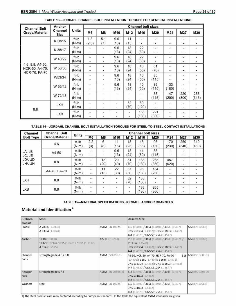
ESR-2854 | Most Widely Accepted and Trusted Page 26 of 30
TABLE 13—JORDAHL CHANNEL BOLT INSTALLATION TORQUES FOR GENERAL INSTALLATIONS
Channel Bolt Grade/Material
Anchor Channel
Size Units
Channel bolt sizes
M6 M8 M10 M12 M16 M20 M24 M27 M30
4.6, 8.8, A4-50, HCR-50, A4-70, HCR-70, FA-70
K 28/15 ft-lb
(N-m) 1.8 5.1 9.6 11 - - - - -
(2.5) (7) (13) (15) - - - - -
K 38/17 ft-lb
(N-m) - -
- -
9.6 (13)
18 (24)
22 (30)
- -
- -
- -
- -
W 40/22 ft-lb
(N-m) - -
- -
9.6 (13)
18 (24)
22 (30)
- -
- -
- -
- -
W 50/30 ft-lb
(N-m) - -
- -
9.6 (13)
18 (24)
40 (55)
51 (70)
- -
- -
- -
W53/34 ft-lb
(N-m) - -
- -
9.6 (13)
18 (24)
40 (55)
85 (115)
- -
- -
- -
W 55/42 ft-lb
(N-m) - -
- -
9.6 (13)
18 (24)
40 (55)
85 (115)
133 (180)
- -
- -
W 72/48 ft-lb
(N-m) - -
- -
- -
- -
- -
85 (115)
147 (200)
220 (300)
255 (345)
8.8 JXH
ft-lb (N-m)
- -
- -
- -
52 (70)
89 (120)
- -
- -
- -
- -
JXB ft-lb
(N-m) - -
- -
- -
- -
133 (180)
221 (300)
- -
- -
- -
TABLE 14—JORDAHL CHANNEL BOLT INSTALLATION TORQUES FOR STEEL-TO-STEEL CONTACT INSTALLATIONS
Channel Bolt Type
Channel Bolt Grade/Material Units
Channel bolt sizesM6 M8 M10 M12 M16 M20 M24 M27 M30
JA, JB JC, JE JD/JUD JH/JUH
4.6 ft-lb
(N-m) 2.2 6 11 18 48 96 170 250 340 (3) (8) (15) (25) (65) (130) (230) (340) (460)
A4-50 ft-lb
(N-m) - -
- -
9.6 (13)
18 (24)
44 (60)
85 (115)
- -
- -
- -
8.8 ft-lb
(N-m) - -
15 (20)
29 (40)
51 (70)
133 (180)
265 (360)
457 (620)
- -
- -
A4-70, FA-70 ft-lb
(N-m) - -
11 (15)
22 (30)
37 (50)
96 (130)
184 (250)
- -
- -
- -
JXH 8.8 ft-lb
(N-m) - -
- -
- -
52 (70)
133 (180)
- -
- -
- -
- -
JXB 8.8 ft-lb
(N-m) - -
- -
- -
- -
133 (180)
265 (360)
- -
- -
- -
TABLE 15—MATERIAL SPECIFICATIONS, JORDAHL ANCHOR CHANNELS
Material and Identification 1)
JORDAHL
product
Steel Stainless Steel
Profile A 283 C (1.0038)
A 633 A (1.0044)
ASTM (EN 10025) 316 (1.4401)/ 316L (1.4404)/ 316Ti (1.4571)
UNS S32304 (1.4362); UNS S31803 (1.4462)
444 (1.4529)/ UNS S31254 (1.4547)
AISI (EN 10088)
Anchor 1018 (1.0038)
1012 (1.0214); 1015 (1.0401); 1015 (1.1132)
A 914 (1.5525)
AISI (EN 10263) 316 (1.4401)/ 316L (1.4404)/ 316Ti (1.4571)/
316LCu (1.4578)
UNS S32304 (1.4362); UNS S31803 (1.4462)
444 (1.4529)/ UNS S31254 (1.4547)
AISI (EN 10088)
Channel
Bolts
strength grade 4.6 / 8.8 ASTM (ISO 898‐1) A4‐50, HCR‐50, A4‐70, HCR‐70, FA‐70 2) 316
(1.4401)/ 316L (1.4404)/ 316Ti (1.4571)
UNS S32304 (1.4362); UNS S31803 (1.4462)
444 (1.4529)/ UNS S31254 (1.4547)
AISI (ISO 3506‐1)
Hexagon
nuts
strength grade 5 / 8 ASTM (EN 20898‐2) 316 (1.4401)/ 316L (1.4404)/ 316Ti (1.4571)
UNS S31803 (1.4462)
444 (1.4529)/ UNS S31254 (1.4547)
AISI (ISO 3506‐2)
Washers steel ASTM (EN 10025) 316 (1.4401)/ 316L (1.4404)/ 316Ti (1.4571)
UNS S31803 (1.4462)
444 (1.4529)/ UNS S31254 (1.4547)
AISI (EN 10088)
1) The steel products are manufactured according to European standards. In the table the equivalent ASTM standards are given.

ESR-2854 | Most Widely Accepted and Trusted Page 27 of 30
TABLE 16—JORDAHL WASHER REQUIREMENTS FOR STAND-OFF INSTALLATIONS1
Anchor Channel Size
Channel Bolt Type
Channel bolt sizes
M8 M10 M12 M16 M20 M24 M27 M30
JTA K 28/15
JD IS0
7093-1 IS0
7093-1 IS0
7089 - - - - -
JTA K 38/17
JH - -
38 x 38 x 5 IS0
7093-1 IS0
7093-1 - -
- -
- -
- -
JTA W 40/22
JC - -
38 x 38 x 5 IS0
7093-1 IS0
7093-1 - -
- -
- -
- -
JTA W 50/30
JB - -
50 x 50 x 6 50 x 50 x 6 50 x 50 x 6 50 x 50 x 6- -
- -
- -
JTA W 53/34
JB - -
50 x 50 x 6 50 x 50 x 6 50 x 50 x 6 50 x 50 x 6- -
- -
- -
JTA W 55/42
JB/ JE
- -
50 x 50 x 6 50 x 50 x 6 50 x 50 x 6 50 x 50 x 6 50 x 50 x 6 - -
- -
JTA W 72/48
JA - -
- -
- -
- -
70 x 70 x 8 70 x 70 x 8 70 x 70 x 8 70 x 70 x 8
JXA W 38/23
JXH - -
- -
38 x 38 x 5 38 x 38 x 5- -
- -
- -
- -
JXA W 53/34
JXB - -
- -
- -
50 x 50 x 6 50 x 50 x 6- -
- -
- -
1Dimensions provided are for square washers, width x length x thickness, in mm.
TABLE 17—JORDAHL ANCHOR CHANNEL PROFILE DESIGNATION ON HEAD OF ANCHOR
Parameter JTA JXA
K 28/15 K 38/17 W 40/22 W 50/30 W 53/34 W 55/42 W 72/48 W 38/23 W 53/34Min. marking on the anchor head in the channel
J 28 J 38 J 40 J 50 J 53 J 55 J 72 J 38 J 53

ESR-2854 | Most Widely Accepted and Trusted Page 28 of 30
FIGURE 8-4—MANUFACTURERS PRINTED INSTALLATION INSTRUCTIONS (MPII) FOR JORDAHL JTA ANCHOR CHANNELS

ESR-2854 | Most Widely Accepted and Trusted Page 29 of 30
FIGURE 8-4—MANUFACTURERS PRINTED INSTALLATION INSTRUCTIONS (MPII) FOR JORDAHL JTA ANCHOR CHANNELS (Continued)

ICC-ES Evaluation Reports are not to be construed as representing aesthetics or any other attributes not specifically addressed, nor are they to be construed as an endorsement of the subject of the report or a recommendation for its use. There is no warranty by ICC Evaluation Service, LLC, express or implied, as to any finding or other matter in this report, or as to any product covered by the report.
Copyright © 2018 ICC Evaluation Service, LLC. All rights reserved. Page 30 of 30
ICC-ES Evaluation Report ESR-2854 LABC and LARC Supplement Reissued April 2018
Revised December 2018
This report is subject to renewal April 2020.
www.icc-es.org | (800) 423-6587 | (562) 699-0543 A Subsidiary of the International Code Council ®
DIVISION: 03 00 00—CONCRETE Section: 03 15 19—Cast-In Concrete Anchors Section: 03 16 00—Concrete Anchors REPORT HOLDER:
JORDAHL GMBH EVALUATION SUBJECT:
JORDAHL ANCHOR CHANNEL SYSTEMS IN CRACKED AND UNCRACKED CONCRETE 1.0 REPORT PURPOSE AND SCOPE
Purpose:
The purpose of this evaluation report supplement is to indicate that the Jordahl Anchor Channel Systems in cracked and uncracked concrete, described in ICC-ES master evaluation report ESR-2854, have also been evaluated for compliance with the codes noted below, as adopted by the Los Angeles Department of Building and Safety (LADBS).
Applicable code editions: 2017 City of Los Angeles Building Code (LABC)
2017 City of Los Angeles Residential Code (LARC)
2.0 CONCLUSIONS
Jordahl Anchor Channel Systems in cracked and uncracked concrete, described in Sections 2.0 through 7.0 of the master evaluation report ESR-2854, comply with LABC Chapter 19 and LARC, and are subject to the conditions of use described in this supplement.
3.0 CONDITIONS OF USE The Jordahl Anchor Channel Systems in cracked and uncracked concrete described in this evaluation report must comply with all of the following conditions:
All applicable sections in the master evaluation report ESR-2854.
The design, installation, conditions of use and identification of the anchoring systems are in accordance with the 2015 International Building Code® (2015 IBC) provisions noted in the master evaluation report ESR-2854.
The design, installation and inspection are in accordance with additional requirements of LABC Chapters 16 and 17, as applicable.
Under the LARC, an engineered design in accordance with LARC Section R301.1.3 must be submitted.
The allowable and strength design values listed in the master evaluation report and tables are for the connection of the anchoring systems to the concrete. The connection between the anchoring systems and the connected members shall be checked for capacity (which may govern).
This supplement expires concurrently with the master report, reissued April 2018 and revised December 2018.