erie 1 boces addendum no - university of...
TRANSCRIPT

University of Missouri ADDENDUM NO. 1 East Campus Plant Growth Facilities Complex Phase 1 – CP170281 East Campus Site Utilities and Infrastructure – CP170282 CannonDesign Project No. 005143.00
Addendum No. 1, Page 1
Date of Addendum: August 4, 2017 Original Date of Contract Documents: July 24, 2017 _____________________________________________________________________________________ Owner Architects and Engineers The Curators of the University of Missouri CannonDesign University of Missouri 1100 Clark Avenue Columbia, Missouri St. Louis, MO 63102 _____________________________________________________________________________________ This Addendum amends Drawings and/or Specifications and/or Addenda for the above titled project, as indicated below, and is hereby incorporated into the Contract Documents as part thereof. Bidders are required to acknowledge receipt of this Addendum in the space provided on the Proposal/Bid Form. _____________________________________________________________________________________ Attachments: Specifications: 1.1, 1.E, Geotech Report Drawings: None issued RFIs: None issued _____________________________________________________________________________________
CP170281-ECPGFC1_CP170282-ECPGFC2 PROJECT MANUAL VOLUME 1
1. SECTION 1.1 – TOC
A. Section 1.1 has been revised and is being reissued as an attachment to this Addendum.
2. SECTION 1.E – SPECIAL CONDITIONS
A. Section 1.E has been revised and is being reissued as an attachment to this Addendum. Additions include clarification for road closures and a Request for Substitution Review Form.
3. GEOTECHNICAL REPORT
A. The Geotechnical Report is being issued as an attachment to this Addendum it should follow 1.H – Alternates in the project manual.
END OF ADDENDUM NO. 1
08.04.17
PROJECT MANUAL FOR: CP170281 – EAST CAMPUS PLANT GROWTH FACILITIES COMPLEX PHASE 1 CP170282 – GENERAL SITE – EAST CAMPUS SITE UTILITY & INFRASTRUCTURE
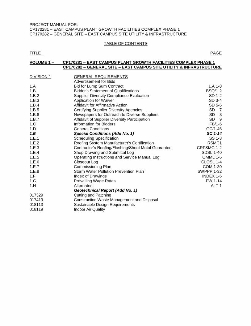
TABLE OF CONTENTS TITLE PAGE VOLUME 1 – CP170281 – EAST CAMPUS PLANT GROWTH FACILITIES COMPLEX PHASE 1 CP170282 – GENERAL SITE – EAST CAMPUS SITE UTILITY & INFRASTRUCTURE DIVISION 1 GENERAL REQUIREMENTS Advertisement for Bids 1.A Bid for Lump Sum Contract 1.A 1-8 1.B Bidder's Statement of Qualifications BSQ/1-2 1.B.2 Supplier Diversity Compliance Evaluation SD 1-2 1.B.3 Application for Waiver SD 3-4 1.B.4 Affidavit for Affirmative Action SD 5-6 1.B.5 Certifying Supplier Diversity Agencies SD 7 1.B.6 Newspapers for Outreach to Diverse Suppliers SD 8 1.B.7 Affidavit of Supplier Diversity Participation SD 9 1.C Information for Bidders IFB/1-6 1.D General Conditions GC/1-46 1.E Special Conditions (Add No. 1) SC 1-14 1.E.1 Scheduling Specification SS 1-3 1.E.2 Roofing System Manufacturer's Certification RSMC1 1.E.3 Contractor’s Roofing/Flashing/Sheet Metal Guarantee CRFSMG 1-2 1.E.4 Shop Drawing and Submittal Log SDSL 1-40 1.E.5 Operating Instructions and Service Manual Log OMML 1-6 1.E.6 Closeout Log CLOSL 1-4 1.E.7 Commissioning Plan COM 1-30 1.E.8 Storm Water Pollution Prevention Plan SWPPP 1-32 1.F Index of Drawings INDEX 1-6 1.G Prevailing Wage Rates PW 1-14 1.H Alternates ALT 1 Geotechnical Report (Add No. 1) 017329 Cutting and Patching 017419 Construction Waste Management and Disposal 018113 Sustainable Design Requirements 018119 Indoor Air Quality
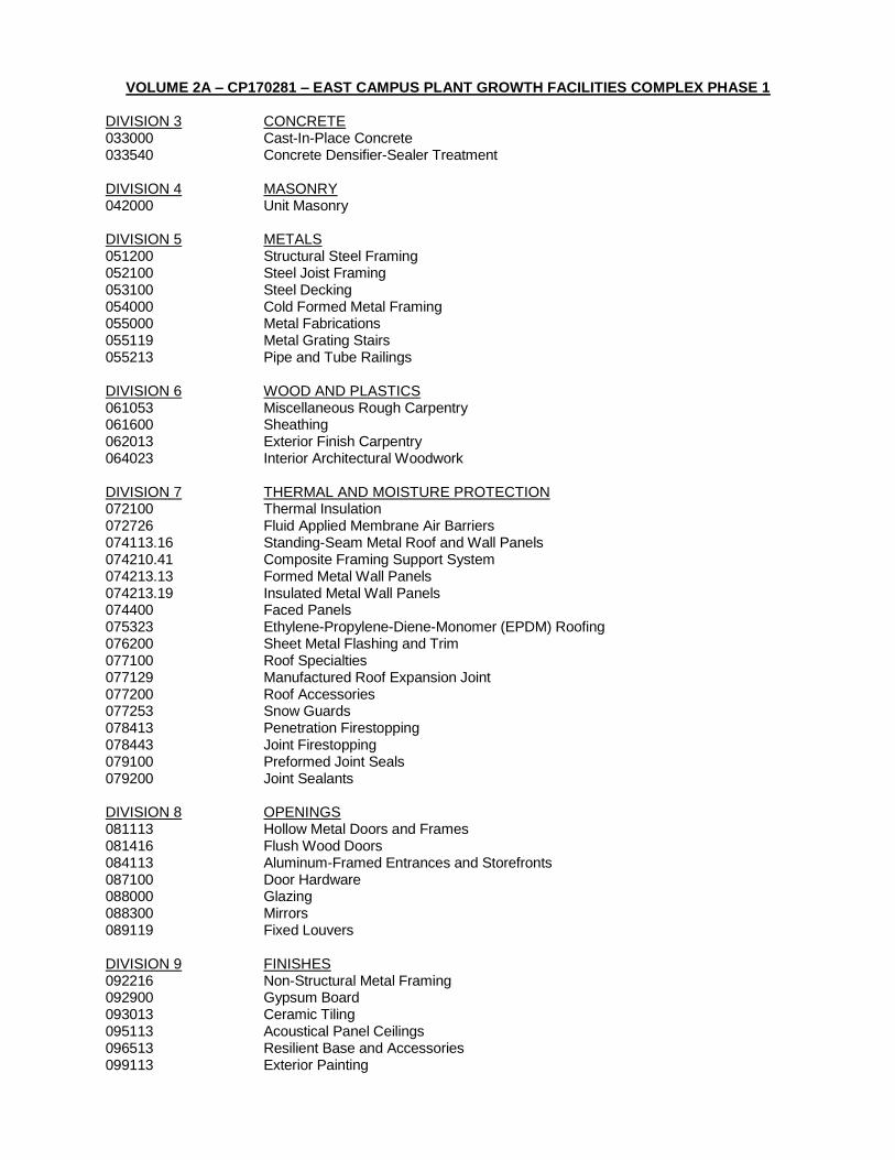
VOLUME 2A – CP170281 – EAST CAMPUS PLANT GROWTH FACILITIES COMPLEX PHASE 1 DIVISION 3 CONCRETE 033000 Cast-In-Place Concrete 033540 Concrete Densifier-Sealer Treatment DIVISION 4 MASONRY 042000 Unit Masonry DIVISION 5 METALS 051200 Structural Steel Framing 052100 Steel Joist Framing 053100 Steel Decking 054000 Cold Formed Metal Framing 055000 Metal Fabrications 055119 Metal Grating Stairs 055213 Pipe and Tube Railings DIVISION 6 WOOD AND PLASTICS 061053 Miscellaneous Rough Carpentry 061600 Sheathing 062013 Exterior Finish Carpentry 064023 Interior Architectural Woodwork DIVISION 7 THERMAL AND MOISTURE PROTECTION 072100 Thermal Insulation 072726 Fluid Applied Membrane Air Barriers 074113.16 Standing-Seam Metal Roof and Wall Panels 074210.41 Composite Framing Support System 074213.13 Formed Metal Wall Panels 074213.19 Insulated Metal Wall Panels 074400 Faced Panels 075323 Ethylene-Propylene-Diene-Monomer (EPDM) Roofing 076200 Sheet Metal Flashing and Trim 077100 Roof Specialties 077129 Manufactured Roof Expansion Joint 077200 Roof Accessories 077253 Snow Guards 078413 Penetration Firestopping 078443 Joint Firestopping 079100 Preformed Joint Seals 079200 Joint Sealants DIVISION 8 OPENINGS 081113 Hollow Metal Doors and Frames 081416 Flush Wood Doors 084113 Aluminum-Framed Entrances and Storefronts 087100 Door Hardware 088000 Glazing 088300 Mirrors 089119 Fixed Louvers DIVISION 9 FINISHES 092216 Non-Structural Metal Framing 092900 Gypsum Board 093013 Ceramic Tiling 095113 Acoustical Panel Ceilings 096513 Resilient Base and Accessories 099113 Exterior Painting
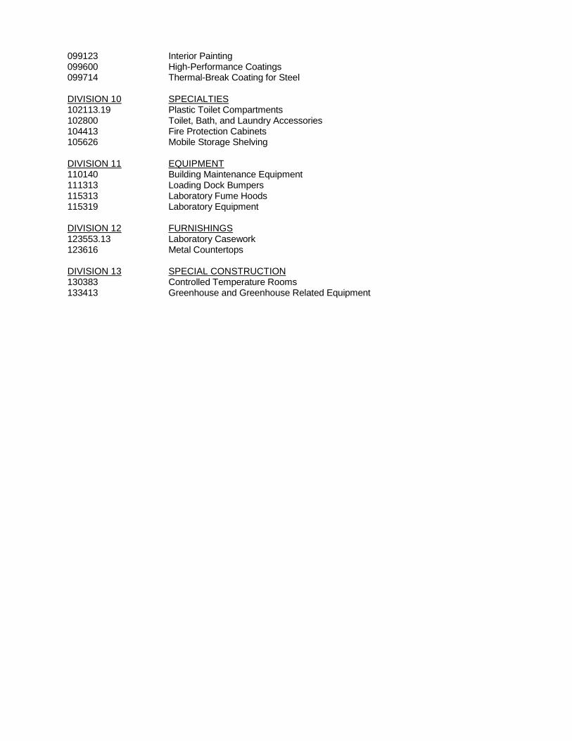
099123 Interior Painting 099600 High-Performance Coatings 099714 Thermal-Break Coating for Steel DIVISION 10 SPECIALTIES 102113.19 Plastic Toilet Compartments 102800 Toilet, Bath, and Laundry Accessories 104413 Fire Protection Cabinets 105626 Mobile Storage Shelving DIVISION 11 EQUIPMENT 110140 Building Maintenance Equipment 111313 Loading Dock Bumpers 115313 Laboratory Fume Hoods 115319 Laboratory Equipment DIVISION 12 FURNISHINGS 123553.13 Laboratory Casework 123616 Metal Countertops DIVISION 13 SPECIAL CONSTRUCTION 130383 Controlled Temperature Rooms 133413 Greenhouse and Greenhouse Related Equipment

VOLUME 2B – CP170281 – EAST CAMPUS PLANT GROWTH FACILITIES COMPLEX PHASE 1
DIVISION 21 FIRE SUPPRESION 210500 Basic Division 21 Requirements 210548 Vibration and Seismic Controls for Fire-Suppression Piping and Equipment 211000 Water-Based Fire Suppression Systems
DIVISION 22 PLUMBING 220500 Common Work Results for Plumbing 220516 Expansion Fittings and Loops for Plumbing Piping 220519 Meters and Gages for Plumbing Piping 220523 General Duty Valves for Plumbing Piping 220529 Hangers and Supports for Plumbing Piping and Equipment 220548 Vibration and Seismic Controls for Plumbing Piping and Equipment 220553 Identification for Plumbing Piping and Equipment 220700 Plumbing Insulation 221116 Domestic Water Piping 221119 Domestic Water Piping Specialties 221123 Domestic Water Pumps 221316 Sanitary Waste, Vent and Storm Piping 221319 Sanitary Waste and Storm Piping Specialties 221429 Sump Pumps 223100 Domestic Water Softeners 223200 Domestic Water Filtration Equipment 223300 Electric domestic Water Heaters 224000 Plumbing Fixtures 226113 Compressed Air Piping for Laboratory and Healthcare Facilities
DIVISION 23 HEATING, VENTILATING, AND AIR CONDITIONING 230010 Basic Division 23 Requirements 230050 Basic Mechanical Materials and Methods 230513 Common Motor Requirements for HVAC Equipment 230516 Expansion Fittings and Loops for HVAC Piping 230517 Sleeves and Sleeve Seals for HVAC Piping 230518 Escutcheons for HVAC Piping 230519 Meters and Gages for HVAC Piping 230523 General Duty Valves for HVAC Piping (Short Form) 230529 Hangers and Supports for HVAC Piping and Equipment 230548 Vibration, Seismic and Wind Controls for HVAC 230553 Identification for HVAC Piping and Equipment 230593 Testing, Adjusting, and Balancing for HVAC 230700 HVAC Insulation 230900 Instrumentation and Control for HVAC 232113 Hydronic Piping 232116 Hydronic Piping Specialties 232123 Hydronic Pumps 232213 Steam and Condensate Heating Piping 232216 Steam and Condensate Piping Specialties 232500 HVAC Water Treatment 233113 Metal Ducts 233300 Air Duct Accessories 233416 Centrifugal HVAC Fans 233600 Air Terminal Units 233713 Diffusers, Registers, and Grilles 233723 HVAC Gravity Ventilators 235700 Heat Exchangers for HVAC 237313 Modular Indoor Central Station Air Handling Units

VOLUME 2C – CP170281 – EAST CAMPUS PLANT GROWTH FACILITIES COMPLEX PHASE 1 DIVISION 26 ELECTRICAL 260010 Basic Division 26 Requirements 260505 Electrical Inspections and Testing 260519 Low Voltage Electrical Power Conductors and Cables (100-600 Volts) 260523 Control Voltage Electrical Power Cables 260526 Grounding and Bonding 260529 Hangers and Supports 260533 Raceways 260535 Boxes and Cabinets 260543 Underground Ducts and Manholes 260544 Sleeves and Sleeve Seals for Raceways and Cabling 260548 Vibration and Seismic Controls 260553 Electrical Identification 260573 Protective Device Coordination 260575 Conduit Rough-In Systems 260578 Multi-Service Boxes and Assemblies 260590 Electrical Service Entrance 260800 Electrical Systems Commissioning 260923 Line Voltage Automatic Lighting Control Equipment 260924 Low Voltage Automatic Lighting Control Equipment 262413 Switchboards 262416 Panelboards 262485 Contactors 262726 Wiring Devices 262800 Protective Devices 262913 Variable Frequency Drives 264113 Lightning Protection System 264313 Surge Protection Devices for Low Voltage Electrical Power Circuits 265100 Interior Lighting 265600 Exterior Lighting DIVISION 27 COMMUNICATIONS 270526 Grounding and Bonding for Communications Systems 270528 Pathways for Communications Systems 270544 Sleeves and Sleeve Seals for Communications Pathways and Cabling 271011 Communications Scope of Work DIVISION 28 ELECTRONIC SAFETY AND SECURITY 284621 Addressable Fire Alarm Systems DIVISION 31 EARTHWORK 311000 Site Clearing 312000 Earth Moving 312300 Excavation and Fill 316329 Drilled Concrete Piers and Shafts DIVISION 32 EXTERIOR IMPROVEMENTS 321123 Aggregate Base Courses 321216 Asphalt Paving 321313 Concrete Paving 323100 Fences and Gates, Infill 323113 Chain Link Fences and Gates 337173.33 Electricity Metering
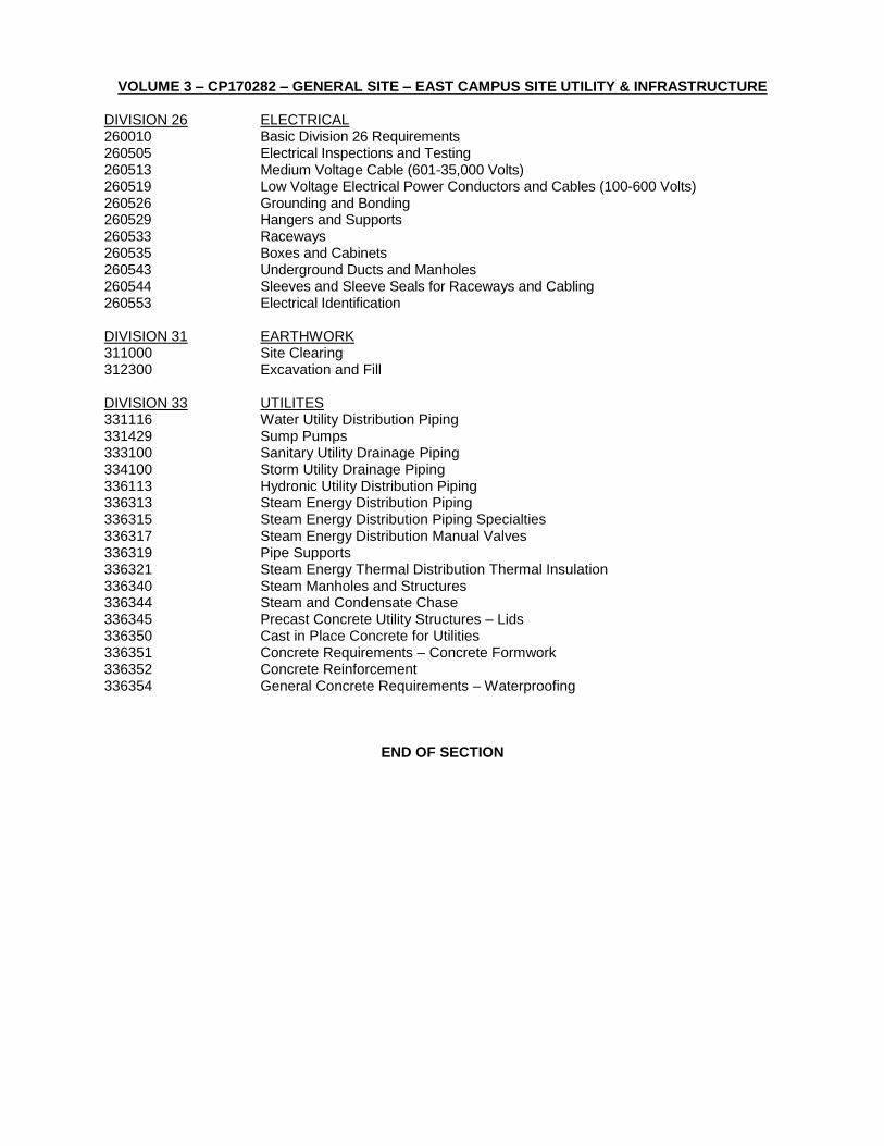
VOLUME 3 – CP170282 – GENERAL SITE – EAST CAMPUS SITE UTILITY & INFRASTRUCTURE DIVISION 26 ELECTRICAL 260010 Basic Division 26 Requirements 260505 Electrical Inspections and Testing 260513 Medium Voltage Cable (601-35,000 Volts) 260519 Low Voltage Electrical Power Conductors and Cables (100-600 Volts) 260526 Grounding and Bonding 260529 Hangers and Supports 260533 Raceways 260535 Boxes and Cabinets 260543 Underground Ducts and Manholes 260544 Sleeves and Sleeve Seals for Raceways and Cabling 260553 Electrical Identification DIVISION 31 EARTHWORK 311000 Site Clearing 312300 Excavation and Fill DIVISION 33 UTILITES 331116 Water Utility Distribution Piping 331429 Sump Pumps 333100 Sanitary Utility Drainage Piping 334100 Storm Utility Drainage Piping 336113 Hydronic Utility Distribution Piping 336313 Steam Energy Distribution Piping 336315 Steam Energy Distribution Piping Specialties 336317 Steam Energy Distribution Manual Valves 336319 Pipe Supports 336321 Steam Energy Thermal Distribution Thermal Insulation 336340 Steam Manholes and Structures 336344 Steam and Condensate Chase 336345 Precast Concrete Utility Structures – Lids 336350 Cast in Place Concrete for Utilities 336351 Concrete Requirements – Concrete Formwork 336352 Concrete Reinforcement 336354 General Concrete Requirements – Waterproofing
END OF SECTION

ALT - 1

Revised and Reissued: August 4, 2017 Addendum No. 1
SC - 1
SECTION 1.E SPECIAL CONDITIONS
1. DEFINITIONS
a. "Drawings"
Drawings referred to in and accompanying Project Manual consist of Drawings prepared by and bearing name of below defined Architect, bearing: CP170281 – EAST CAMPUS PLANT GROWTH FACILITIES COMPLEX PHASE 1, July 24, 2017 CP170282 – GENERAL SITE – EAST CAMPUS SITE UTILITY & INFRASTRUCTURE, July 24, 2017
b. Architect CannonDesign 1100 Clark Avenue St. Louis, MO 63033 Phone: 314-241-6250
c. Mechanical & Electrical Engineer
CannonDesign 1100 Clark Avenue St. Louis, MO 63033 Phone: 314-241-6250
d. Structural Engineer
David Mason & Associates 800 South Vandeventer Avenue St. Louis, MO 63110 Phone: 314-534-1030
e. Civil Engineer
Civil Design Inc. (CDI) 1552 South 7th Street St. Louis, MO 63104 Phone: 314-863-5570
f. Technology and Fire Alarm Stahl & Ponder, Inc. 3207 Sutton Blvd. Maplewood, MO 63143 Phone: 314-644-5660
g. Architecture Consultant – Interiors WA Architects, Inc. 611 N. Tenth Street, Suite 600 St. Louis, MO 63101 Phone: 314-492-5093
h. Greenhouse Consultant Rough Brothers, Inc. 5513 Vine Street Cincinnati, OH 45217 Phone: 513-618-7219
i. Other Definitions: See Article 1., General Conditions.
Revised and Reissued: August 4, 2017 Addendum No. 1
SC - 2
2. SPECIAL SCHEDULING REQUIREMENTS
a. Special scheduling requirements supplemental to the bid form. Utility shut down shall be limited to 60 days. Roads shall be repaired and in working order 60 days after initial closure. Road closure of East Campus Drive & East Campus Loop - Road closure to be limited to the following specific time windows:
East Campus Loop: For CW Line and Water Line work to replace 17 feet with ductile iron where it will pass below new Steam Chase (Sheet UC0301). This work must be completed between November 1, 2017 and March 15, 2018, to avoid the hot weather season. One lane of East Campus Loop must remain open at all times. East Campus Drive & East Campus Loop: Road closure shall be limited to May 14, 2018 through August 3, 2018 only, to facilitate the bulk of utility work in this area. Temporary directional signage for the closed intersection detour will be required in the East Campus vicinity to alert all traffic of the road closure. A temporary bi-pass through a portion of the west side Parking Lot AV14 (west of East Campus Drive) will be designated during this timeframe. Refer to diagram at the end of SC Section. (Add No. 1)
3. SCOPE OF WORK
a. The Contractor shall furnish all labor, materials, tools, equipment necessary for, and incidental to, construction of this project as indicated on Drawings and specified herein.
b. Work shall include everything requisite and necessary to finish work properly,
notwithstanding that every item of labor or materials or accessories required to make project complete may not be specifically mentioned.
c. General Description of Work:
(1) Project consists of construction of a new plant growth facility with associated site
and utility improvements. (2) The project shall seek certification by the US Green Building Council LEED for
New Construction and Major Renovations. This shall include the planning, documenting and archiving of credits contributing to the project’s certification as required.
4. LOCATION
Work shall be performed under this Contract on campus of the University of Missouri, at Southwest portion of Parking Lot AV14, street address will be 1140 East Campus Drive, Columbia, MO 65211.
5. NUMBER OF CONSTRUCTION DOCUMENTS
a. The Owner's Representative will furnish the Contractor a copy of executed Contract and digital copies of the Drawings and Specifications.
b. Contractor to provide their own paper copies.
6. SUBMITTALS
a. The Contractor shall submit for approval to the Architect, equipment lists and Shop Drawings, as expediently as possible. Failure of the Contractor to submit Shop Drawings

Revised and Reissued: August 4, 2017 Addendum No. 1
SC - 3
in a timely manner will result in the Owner holding back Contractor payments. (See General Conditions)
b. The material and equipment lists shall be submitted and approved before any material or equipment is purchased and shall be corrected to as-built conditions before the completion of the project.
c. The Contractor shall submit to the Architect copies of all required Shop Drawings, material and equipment lists for the Architect’s and the Owner’s sole use as outlined in Division 01 Section “Submittal Procedures”. The Contractor shall submit additional copies required for his own use. Additional copies will be reviewed by the Architect and returned to the Contractor marked accordingly.
d. The Contractor shall submit electronic versions of all required Shop Drawings, material and
equipment lists. The Contractor shall upload all Shop Drawings to a secure information sharing website determined by the Owner notifying the Owner and Consultant that these shop drawings are available for review. Each submittal shall have the General Contractors digital stamp affixed to the first page signifying their review and acceptance. Review comments, approvals, and rejections will be posted on this same site with notification to the contractor. Submittals requiring a professional seal shall be submitted hard copy with a manual seal affixed.
(1) The Contractor shall identify each submittal item with the following:
(a) Project Title and Location (b) Project Number (c) Supplier’s Name (d) Manufacturer’s Name (e) Contract Specification Section and Article Number (f) Contract Drawing Number (g) Acrobat file name: Spec Section_Times Submitted-Spec Title: 033000
_01-Cast In Place Concrete.pdf
(2) Reference the accompanying Shop Drawing and Submittal Log at the end of this section (1.E.3) for required submittal information.
e. The Contractor shall submit to the Architect two (2) bound (three ring binder) copies and one (1) electronic (pdf) copy of all required Operating Instructions and Service Manuals for the Architect’s and the Owner’s sole use prior to completing 50% of the adjusted contract. Payments beyond 50% of the contract amount may be withheld until all Operating Instructions and Service Manuals are received as referenced in the accompanying Operating Instructions and Service Manual Log at the end of this section (1.E.4).
f. The Contractor shall submit to the Owner’s Representative all items referenced in the
accompanying Closeout Log (1.E.5) within 30 days following substantial completion of the work. The Owner’s Representative will maintain the closeout log and include as an agenda item at all coordination meetings.
g. The Contractor shall comply with the submittal requirements in Section 018113 Sustainable
Design Requirements. 7. NOTIFICATION
Before beginning Demolition Work or service outages, the Contractor shall provide, at minimum, seventy-two (72) hours advance notice to Owner’s Representative for purpose of verifying utility locations including, but not limited to, gas, telecommunications, electric, water, steam, sewer, and nitrogen. Contractor shall minimize the number of outages, minimize the length of outages and related work shall be continuous until the utility is restored.

Revised and Reissued: August 4, 2017 Addendum No. 1
SC - 4
8. USE OF PREMISES
a. Access: Access to construction site shall be as indicated on Drawings and as directed by the Owner's Representative.
b. Parking:
(1) Free parking for contractor employees is available in the Ashland Road Contractor
lot on an as available basis. This space is for use by contractor employees for parking their personal vehicles only and is not to be used for staging or storage.
c. Storage of materials: The Contractor shall store all materials within project limits. The Contractor shall confine apparatus, materials, and operation of workers to location established by the Owner's Representative. The Contractor shall not unreasonably encumber premises with materials. In addition, storage trailer locations may be available within 1-1/2 miles of project site as directed by the Owner’s Representative. Storage trailer locations shall be subject to approval by the Owner's Representative and are available to the Contractor without cost.
d. The Contractor shall protect absorptive materials in accordance with requirements in
Section 018119 Indoor Air Quality. e. Utilities: Steam, water, sewer, and electricity can be obtained from existing utilities at
locations designated by the Owner's Representative at the following rates:
Provisions for obtaining power, including temporary extensions, shall be furnished and maintained by the Contractor. Upon completion of the work, such extensions shall be removed and any damage caused by use of such extensions shall be repaired to the satisfaction of the Owner's Representative, at no cost to the Owner. Electricity: $0.10 per kWh Steam (return condensate): $18.76 per klb Steam (dumped condensate): $20.55 per klb Water: $3.25 per kgal Chilled Water: $$0.335 per ton-hour (12,000 btu/ton)
e. Restroom: The Contractor shall provide and maintain, in a sanitary condition, chemical type portable toilet facilities at work site for use by his personnel. Toilets and toilet location shall be subject to approval by the Owner's Representative.
f. The University of Missouri is tobacco free, including all streets, rights of way, properties
owned, operated, leased or controlled by the University of Missouri. Violation of the policy is defined as any tobacco products, including e-cigarettes.
g. Landfill: The Contractor shall not use the Owner’s landfill. Dumping or disposal of
excavated or demolition materials on Owner’s property shall not be permitted. The Contractor shall remove and legally dispose of excavated or demolished materials off the Owner’s property. The Contractor shall comply with the requirements in Section 017419 Construction Waste Management Plan.
h. Care of Project Work Site: The contractor shall be responsible for maintaining the
construction site in a reasonably neat and orderly condition by regular cleaning and mowing of the premises as determined by the Owner’s Representative.
i. Discharge to Sewer Request: The University of Missouri’s MS4 permit and NPDES Storm Water Discharge Permits along with the City of Columbia’s POTW Operating Permit as well as local ordinances, and state and federal environmental regulations prohibit hazardous materials from being disposed into either the storm water or sanitary sewer systems. Unless specifically approved, all chemical products such as paints, dyes, lawn

Revised and Reissued: August 4, 2017 Addendum No. 1
SC - 5
care products, maintenance products, and oil are prohibited from drain disposal. Any product, including contaminated water, being discarded into the storm water or sanitary sewer systems requires written approval from the Owner through a formal “Discharge to Sewer Request” form obtained at Discharge to Sewer Request Form. The contractor should submit the form to the Owner’s Representative, not to the Department of Environmental Health and Safety as the form indicates.
j. Field Office Recycling: Provide recycling for; at a minimum, paper, cardboard, plastic, glass, and metal.
k. All concrete waste material including washout water shall be totally contained and removed from the Owner’s property.
l. Artifacts Found During Construction: Contractor shall immediately notify the Owner’s
Representative when artifacts are uncovered or found during the demolition or construction process. Artifacts include, but are not limited to, tools, drawings (construction or other), photographs, books and other objects/devices which may hold historical importance/significance. Do not remove or disturb the object(s) in question. Artifacts are not considered part of demolished materials and shall remain the property of the University of Missouri.
m. “Permit Required Confined Space” Entry Communication and Coordination
See 29 CFR 1926 Subpart AA – Confined Spaces in Construction for requirements for
practices and procedures in a permit required confined space. Note: The University will
provide to the Contractor a list of all known “permit required confined spaces”.
The following are the known locations of “permit required confined spaces” currently
identified within the project limits:
(1) Telecom manhole #406
(2) Electric manhole #298
(3) Steam manhole #453
The hazards or potential hazards in each “permit required confined space” or the reason
it is a “permit required confined space”:
(1) Oxygen deficient or toxic/hazardous atmosphere
(2) Extreme temperature
(3) Fall protection
(4) Traffic
Any precautions that the Owner or previous contractors have implemented for the
protection of employees in the “permit required controlled space”:
(1) Ventilation & Outside Air
(2) Fall protection
(3) Safety barricades & Signage
The above list of known confined spaces within the project limits may not be a complete
listing. Each contractor shall survey the project to identify all confined spaces. It is
incumbent upon each contractor to list all “permit required spaces”.
The Contractor shall notify the Owner’s Representative if 1) conditions change resulting
in a non-permit required confined space being reclassified to a “permit required confined
space” after evaluation of the space by a competent person; 2) a space previously
thought to be non-permit required space is classified as a “permit required confined
Revised and Reissued: August 4, 2017 Addendum No. 1
SC - 6
space” after evaluation by a competent person; or 3) during the course of construction a
“permit required confined space” is created after evaluation by a competent person.
The Contractor shall submit to the Owner’s Representative a copy of the cancelled
confined space entry permit and a written report summarizing the permit space program
followed and all hazards confronted or created during entry operations. This information
shall be submitted within one week of cancelling the permit.
9. PROTECTION OF OWNER'S PROPERTY
a. The Contractor shall be responsible for repair of damage to building exterior and interior, drives, curbs, streets, walks, grass, shrubbery and trees, which was caused by workmen or equipment employed during progress of work. All such repairs shall be made to satisfaction of the Owner's Representative, at no cost to the Owner, or reimburse the Owner if the Owner elects to make repairs. For landscape damage, the Owner shall make such repairs. Compensation for these repairs shall be determined by the Owner's Representative using the "Valuation of Landscape Trees, Shrubs, and other Plants" as published by the International Society of Arboriculture, as last revised.
b. Construction Project Fencing:
(1) Fencing requirements: Shall be constructed by the Owner. Contractor is to
maintain and modify construction fencing as required to accommodate progress of the work.
(2) Use of ribbon, snow fence, chicken wire, rope, and wooden barricades as fencing
is prohibited.
(3) Fencing shall be maintained in an "as-installed" condition throughout the life of the project.
c. Preserving and Protecting Existing Vegetation:
(1) Protection and compensation for damages:
(a) Trees and shrubs within work area designated to remain shall be protected
from damage during construction by fixed chain link fencing or armoring as indicated on Drawings or specified herein. Plant protection devices shall be installed before work has begun and shall be maintained for duration of work unless otherwise directed by Owner's Representative.
(b) In the event that damage(s) to the Owner's trees, shrubs or vegetation
occurs as a result of the Contractor's unauthorized operations, the Contractor shall pay or allow to the Owner compensation for said damage(s). Compensation shall be determined by the Owner's Representative using the "Valuation of Landscape Trees, Shrubs, and other Plants" as published by the International Society of Arboriculture, as last revised.
(2) Plants within work area designated for removal shall be removed by Contractor. (3) To prevent compaction of soil over tree roots, vehicles or equipment shall not at
any time park or travel over, nor shall any materials be stored within drip line of trees designated to remain.
(4) Owner's Representative will stop work immediately when proper measures are not being employed to protect trees and shrubs. Contractor will be notified to resume

Revised and Reissued: August 4, 2017 Addendum No. 1
SC - 7
work after required protection measures are implemented.
(5) Pruning of limbs necessary to repair damage or provide clearance for work shall be done by the MU Landscape Services Department, trained tree maintenance personnel at the direction of the Owner’s Representative. Limbs shall be cut off cleanly and cut surfaces treated according to established horticultural standards.
10. SUBSTITUTIONS and EQUALS
a. Substitutions are defined in General Conditions article 3.11.8 for and Equals are defined General Conditions Article 3.12.
b. Substitutions and/or Equals of the item(s) listed below will be allowed only prior to receipt of bids provided that a written request for approval has been received by both the Architect and the Owner at least ten calendar days prior to the date for receipt of Bids. All other substitution and/or Equals items shall follow the procedures set forth in the General Conditions.
Item Specification Section Brick 042000 Sterilizer 115319 Greenhouse system 133413 Greenhouse controls 133413 Greenhouse equipment 133413 Air handling units 237313 Pumps 232123 Heat exchangers 235700 Exhaust fans 233116 Hydronic Piping Specialties 232116 Autoclaves 115319 Bulk sterilizer 115319 Seed drying room 130383 Seed storage room 130383 Plumbing fixtures 224000 Lighting controls 265100
To be considered, bidder’s proposal shall include a complete description of the proposed substitution and/or equal and a comparison of significant qualities of the proposed substitution and/or equal with those specified including drawings, performance and test data, and other information necessary for an evaluation. The Architect's decision on the approval or disapproval of a proposed substitution and/or equal shall be final. All substitution requests to be submitted on attached form (included at the end of special conditions).
c. If the Architect and Owner approve a proposed substitution prior to receipt of Bids, such
approval will be set forth in an Addendum. Bidders shall not rely upon approval made in any other manner.
d. No substitutions and/or equal will be allowed for the following items:
Item Specification Section Lock Cylinders [Best] 087100 – Door Hardware Knox Box 087100 – Door Hardware Chilled Water & Hot Water Meters 230900 – Controls Systems Steam Meters 230900 – Controls Systems

Revised and Reissued: August 4, 2017 Addendum No. 1
SC - 8
11. CODES AND STANDARDS
The Contractor shall comply with applicable codes and standards as listed in General Conditions. The following codes and standards shall also apply:
a. City of Columbia - Sewer Line Installation Standards - Department of Public Works
“All sanitary sewer construction shall be in accordance with the City of Columbia Specifications and Standards and in conformance with the rules and regulations of the Missouri Clean Water Commission.”
b. The US Green Building Council’s Green Building Rating System, LEED for New Construction and Major Renovations version 2009.
12. PERMITS
Before commencement of Boilers, Water Heaters or Pressure Vessels the Contractor must obtain an installation permit from the State of Missouri, Division of Fire Safety, Boiler and Pressure Unit as required by 11 CSR 40-2.010 through 11 CSR 40-2.065. The permit applications are available at http://www.dfs.dps.mo.gov/programs/bpv/ . .
13. SPECIALTIES
a. Owner furnished topsoil: The Owner shall place Owner provided topsoil and grade to the finish elevation as indicated in the contract. The Owner will deliver the topsoil to the project site in the quantity required. The contractor is required to notify the Owner a minimum of five working days in advance of the needed topsoil. Topsoil shall be placed with rubber tracked equipment to minimize compaction. Placement shall be sequenced to minimize compaction and damage to the topsoil. Topsoil or subsoil damaged, contaminated, or compacted during topsoil placement shall be repaired or replaced as directed by the Owner’s Representative. Hand work shall be required next to adjacent structures and around utilities. Erosion control measures shall be maintained throughout and after topsoil placement.
(1) The sub-grade is to be left at minus six inches (6”) in all areas unless indicated
otherwise. All planting bed sub-grades are to be left a minus eighteen inches (18”). The contractor is to remove all deleterious material from the sub-grade prior to placing topsoil. All subgrade areas shall contain at least 6” of subsoil, (ie. cover clean rock backfilled areas). All subgrade areas shall be “ripped” a minimum of 6” deep and a maximum of 12” apart in opposite directions with minimal tire traffic to follow. All exposed deleterious material and unacceptable rock shall be removed.
(2) The contractor shall adjust all yard boxes valve boxes, pull boxes, cleanouts, and manhole lid rings etc. (includes irrigation, sewers, water and electric), to the indicated finish grade.
(3) Final plantings will be by the Owner. The Owner will water and maintain all seed,
sod and landscaping.
a. 14. PRE-BID INSPECTION
All pre-bid inspections of work areas shall be scheduled with pre-bid inspection guide, telephone: (573) 882-2228.

Revised and Reissued: August 4, 2017 Addendum No. 1
SC - 9
15. ROOF WARRANTY REQUIREMENT
a. The Contractor shall submit, before the first progress payment, a copy of University of Missouri Roof System Manufacturer's Certification, which shall be manually signed by an authorized representative of Manufacturer of each proposed roofing system. Certification shall have original signature.
b. Following final inspection and acceptance of the roofing system(s) by the Owner and the roofing system manufacturer(s), the Contractor shall submit a manually signed standard warranty agreement provided and executed by the roofing system manufacturer for each roofing system provided. Standard warranty agreement(s) shall be of the duration specified in Division 7.
c. University of Missouri three (3) year Contractor’s Roofing/Flashing/ Sheetmetal Guarantee shall be signed by the roofing contractor after final inspection and acceptance of each roofing system by Manufacturer and by Owner.
d. The Roofing contractor or subcontractor shall provide the Owner with an Application for a Roof Warranty.
16. MODIFICATIONS TO INFORMATION TO BIDDERS
a. Information to Bidders:
(1) Referenced Information to Bidders, Page IFB/6. Add new Article 15.9.2 as follows:
15.9.2.1 Within 48 hours of the receipt of bids, the apparent low bidder shall submit to the Director of Facilities Planning and Development an “Affidavit of Supplier Diversity Participation” for every diverse subcontractor or supplier the bidder intends to award work to on the contract. The affidavit will be signed by both the bidder and the diverse firm.
17. MODIFICATION TO INFORMATION FOR BIDDERS: BIDDERS STATEMENT OF
QUALIFICATIONS
a. Information For Bidders
(1) Reference: Information for Bidders, Article 8.4
Insert new Article 8.4 to read as follows:
In addition to the Bidder’s Statement of Qualifications, the Bidder must also submit evidence and meet the following qualifications:
The project requires the services of a prime contractor who has demonstrated success in completing process/power plant work in an operating plant environment with little or no interruption of plant operations.
(a) MINIMUM QUALIFICATIONS
(i) The schedule for the project is aggressive and requires a contractor
with a successful track record of managing projects with average monthly expenditures of more than $1-million
(ii) Successful completion of one project of similar type and scope.

Revised and Reissued: August 4, 2017 Addendum No. 1
SC - 10
(iii) Successful completion of at least three projects of $15-million or greater
value. Submit references for the three most recent projects over $15-million in value.
(vi) Successful and sustained track record of effectively utilizing
project/schedule management software for at least the last two years.
(b) QUALIFICATION SUBMITTALS
(i) Submitted qualification packages should include the following information:
Project and Schedule - Management Experience managing projects with equal or greater
schedule demands. - Demonstrated and consistent on-time completion success
Project Organization / Personnel - Key project team members and their resume - Project team roles and responsibilities of team members - Reporting/accountability procedures - Quality control program and procedures
Organizational Support - Home office support - Labor and subcontractor relations - Submittal processing procedures - Material ordering/tracking/delivery Procedures - Cost accounting support - Financial stability/capacity - Record of mentoring and supporting Supplier Diversity
Subcontractor Participation
(ii) Packages must include the following items:
Corporate Organizational Charts
Project Organizational Charts
Summary of Similar Projects
Client References
Resumes – resumes for each key individual proposed for the project, include: position in the firm, project responsibility, education, license or registration and relevant experience over the last five years.
Financial Statements and/or Evidence of Bonding Capacity
Sample progress reports and schedules
Brief Narratives indicating how the Contractor intends to manage this project, including subcontractors.
(c) QUALIFICATION PROCEDURE
(i) All qualification information and supporting materials must be submitted
with your bid. Following the bid date, the Owner reserves the right to request additional information material to evaluate qualifications. Failure of the Contractor to demonstrate their ability to comply with these qualifications may be grounds for the Owner not recommending aware of the Contract.

Revised and Reissued: August 4, 2017 Addendum No. 1
SC - 11
18. MODIFICATIONS TO GENERAL CONDITIONS
a. General Conditions:
(1) Reference: General Conditions Article 11.2.1 Commercial General Liability.
Delete in the first sentence of 11.2.1: “$2,000,000 per occurrence, $5,000,000 in general aggregate, $5,000,000 products and completed operations aggregate and $1,000,000 personal injury and advertising injury” and insert: “$2,000,000 per occurrence, $15,000,000 in general aggregate, $15,000,000 products and completed operations aggregate and $1,000,000 personal injury and advertising injury”
19. PROJECT SCHEDULING
The project scheduling specification for the project are included immediately after the Special Conditions. For this project the Contractor shall meet the following scheduling requirements. Contractor Schedule – Contractor is responsible for the schedule and he may provide with in-house personnel or hire a third party scheduling consultant. See Contractor Schedule Specification included in these documents.
20. PROJECT COORDINATION
a. Coordinate construction operations included in various Sections of these Specifications to assure efficient and orderly installation of each part of the Work. Coordinate construction operations included under different Sections that depend on each other for proper installation, connection, and operation.
(1) Schedule construction operations in the sequence required to obtain the best
results where installation of one part of the Work depends on installation of other components, before or after its own installation.
(2) Coordinate installation of different components to assure maximum accessibility
for required maintenance, service, and repair. (3) Make provisions to accommodate items scheduled for later installation.
b. Coordination Drawings: Within one hundred twenty (120) days of Notice to Proceed provide
coordination drawings for the integration of the Work, including work first shown in detail on shop drawings or product data. Show sequencing and relationship of separate units of work which must interface in a restricted manner to fit in the space provided, or function as indicated.
(1) Show the interrelationship of components shown on separate shop drawings. (2) Indicate required installation sequences. (3) Call attention in advance to Architect of any dimensional or detail information
needed to complete the coordination drawings.
c. BIM Drawings: Complete building drawings of the mechanical rooms and primary north/south building corridor shall be modeled and coordinated by the General Contractor with cooperation from all sub-contractors.
Revised and Reissued: August 4, 2017 Addendum No. 1
SC - 12
23. BUILDING SYSTEM COMMISSIONING
a. Contractor shall provide all personnel and equipment required to complete the commissioning activities referenced in the Commissioning Plan. The requirements of the commissioning plan shall be completed in their entirety before substantial completion and submitted as referenced in the Closeout Log.
b. The contractor shall designate a competent person, separate from the superintendent or
Project Manager, to act as the contractor’s commissioning coordinator. The commissioning coordinator is responsible for planning, scheduling, coordinating, conducting and verifying all commissioning activities required by the commissioning plan and ensuring all building systems are complete, operable and ready for use by the Owner. At a minimum, building ventilation systems, chilled/hot water generation systems, hydronic distribution systems, power distributions systems and fire detection and alarm systems, as applicable.
24. MECHANICAL, ELECTRICAL, PLUMBING (MEP) PRE-INSTALLATION MEETING(S)
a. Before the start of MEP installation, the Owner’s Representative will convene an MEP pre-installation meeting. Meeting participants to include contractor (including MEP subcontractors), Owner’s Representative and additional contractor and University operational staff invited by the Owner’s Representative. Topics will include underground rough-ins, steam piping, chilled water piping, sprinkler piping, hot water piping, electrical system, duct, telephone/data wiring, control wiring. Additional meetings will be conducted as required for the review of coordination drawings and scope specific installations. Cross section drawings of corridor ceilings and other congested areas will be of highest priority and will be reviewed prior to the start of installations in the affected areas. Meeting minutes and sign-up sheet will be transcribed by contractor and distributed to attendees.
25. COST BREAKOUT FOR OWNER’S ACCOUNTING PURPOSES
a. Contractor will be required to submit the following cost breakout on company letterhead prior to the end of next business day following the bid opening: (1) Cost Breakout #1 – CP170281 – East Campus Plant Growth Facilities Complex
Phase 1: Break out the portion of Base Bid cost associated with all work included as a part of this project package. Include only the work defined by the CP170281 portion of documents, including the portion of General Conditions related to this portion of work. This breakout shall represent the total of the schedule of values for this portion of work that is due later.
(2) Cost Breakout #2 – CP170282 – East Campus Site Utilities & Infrastructure Package: Break out the portion of Base Bid cost associated with all work included as a part of this project package. Include only the work defined by the CP170282 portion of documents, including the portion of General Conditions related to this portion of work. This breakout shall represent the total of the schedule of values for this portion of work that is due later.
b. Contractor will be required to submit two (2) separate schedule of values as follows, within 30-days of Notice to Proceed:
(1) CP170281 – East Campus Plant Growth Facilities Complex – Phase 1 (2) CP170282 – East Campus Site Utilities & Infrastructure Package

Revised and Reissued: August 4, 2017 Addendum No. 1
SC - 13
26. PROJECT MANAGEMENT/COMMUNICATION REQUIREMENTS
a. The Contractor shall be represented by both a competent full-time Project Manager and a full-time (at the site), competent superintendent with no other assigned duties or responsibilities from the beginning of the work until its final acceptance, unless otherwise permitted by the Owner’s Representative. The superintendent for the Contractor for the general building work shall exercise general supervision over all subcontractors of any tier engaged on the work with decision-making authority of the Contractor.
b. The Contractor shall furnish on-site Internet access for use by his Project Manager and
superintendent. The contractor shall utilize the Owner’s secure information sharing system for submittals, construction payment process, change orders, RFI’s/ASI’s, O&M manuals and all other project manual requirements as directed by the Owner’s Representative. Field staff are also required to utilize this software as directed by the Owner’s Representative.
27. SAFETY PRECAUTIONS AND PROGRAMS
a. The Bidder’s Statement of Qualifications includes a requirement that the Bidder provide its Worker’s Compensation Experience Modification Rates (EMR) and Incidence Rates for the three recent years. The Bidder shall also include the EMR and Incidence Rates of listed major subcontractors on the Bid for Lump Sum Contract. If the EMR exceeds 1 or the Incidence Rate exceeds 13, the Contractor or major subcontractor shall take additional safety measures including, but not limited to, developing a site specific safety plan and assigning a Safety Manager to the Project to perform inspections on a schedule as determined acceptable by the Owner with written reports to be submitted to the Owner. The Owner reserves the right to reject a Bidder or major subcontractor whose rates exceed these stated rates.
b. The contractor shall provide Emergency Contact Information for the Contractor’s on-site
staff and home office management as well as contact information for all major subcontractor personnel. This information shall contain business and personal phone numbers for each individual for contact during or after hours in case of an emergency. This information shall be submitted within 15 days of the Notice to Proceed.
29. WARRANTY WALKTHROUGH Contractor shall attend a walk-thru with the Owner at 11 months after acceptance to review and
document any warranty items to be addressed as part of the 12 month warranty stated in article 3.1 of the General Conditions.
30. DELEGATED DESIGN
a. The following sections contain requirements for Delegated Design: Volume 2: ECPGFC1 Delegated Design 051200 – Structural Steel 052100 – Steel Joist Framing 054000 – Cold-Formed Metal Framing 055000 – Metal Fabrications 055119 – Metal Grating Stairs 055213 – Pipe and Tube Railings 061053 – Miscellaneous Rough Carpentry 084113 – Aluminum-Framed Entrances and Storefronts 088000 – Glazing 092216 – Non-Structural Metal Framing 105626 – Mobile Storage Shelving 110140 – Building Maintenance Equipment

Revised and Reissued: August 4, 2017 Addendum No. 1
SC - 14
115313 – Laboratory Fume Hoods 123553.13 – Laboratory Casework 123616 – Metal Countertops 133413 – Greenhouse and Greenhouse Related Equipment 210548 – Vibration and Seismic Controls for Fire Suppression Piping and Equipment 211000 – Water-Based Fire Suppression Systems 220516 – Expansion Fittings and Loops for Plumbing Piping 220548 – Vibration and Seismic Controls for Plumbing Piping and Equipment 230529 – Hangers and Supports for HVAC Piping and Equipment 230548 – Vibration, Seismic, and Wind Controls for HVAC 230900 – Direct Digital Control (DDC) System for HVAC 237313 – Modular Indoor Central-Station Air-Handling Units 260529 – Hangers and Supports 260543 – Underground Ducts and Manholes 260548 – Vibration and Seismic Controls 260573 – Protective Device and Coordination Studies 264113 – Lightning Protection Systems 323100 – Fences and Gates 323113 – Chain Link Fences and Gates Volume 3: ECSUI Delegated Design 220548 – Vibration and Seismic Controls for Plumbing Piping and Equipment 260529 – Hangers and Supports 260543 – Underground Ducts and Manholes 260553 – Electrical Identification 334100 – Storm Utility Drainage Piping 336345 – Precast Concrete Utility Structures - Lids
31. NOTIFICATION OF SEISMIC REQUIREMENTS
a. The project has been designed according to the ICC International Building Code, 2015 Edition and is required to comply with the requirements for Seismic Design Category “D”. All trades, including, but not limited to: general work, ceilings, plumbing, fire protection, HVAC, electrical, etc. are required to comply with seismic design on this project as indicated in the specifications and on the drawings. The structural drawings, specifically sheet S0001, contain information that is to be used for seismic design compliance. Coordination of all components for a clean installation is critical. Design companies which may be utilized for this service are indicated below. 1. Simon & Struemph Engineering
Daniel Struemph, PE 210 Park Ave Columbia, MO 65203 573 499-1944 www.selectsse.com
2. Other engineers which meet requirements as selected by Contractor.
END OF SECTION

University of Missouri Issued: August 4, 2017 East Campus Plant Growth Facilities Complex Phase 1 – CP170281 Addendum No. 1 East Campus Site Utilities and Infrastructure – CP170282 CannonDesign Project No. 005143.00
REQUEST FOR SUBSTITUTION REVIEW FORM 004325.1 - 1
REQUEST FOR SUBSTITUTION REVIEW FORM
Note: Use separate form for each material, product or equipment item.
Date: Request No.:
Specification Section_________________, Article__________________, Paragraph
Name of material, product or equipment item specified in Project Manual or Drawings:
Name of material, product or equipment item submitted for review:
Qualities that differ from specified product or system:
Name of Manufacturer (Fabricator):
Address
__________________________________________________ (________) City, State and Zip Telephone
Name of Vendor/Supplier
Address
__________________________________________________ (________) City, State and Zip Telephone

University of Missouri Issued: August 4, 2017 East Campus Plant Growth Facilities Complex Phase 1 – CP170281 Addendum No. 1 East Campus Site Utilities and Infrastructure – CP170282 CannonDesign Project No. 005143.00
REQUEST FOR SUBSTITUTION REVIEW FORM 004325.1 - 2
Reason for requesting review:
Will proposed item affect other materials or systems, such as dimensional revisions, redesign of structure,
or modifications to other work? Yes No
If “Yes”; describe the affect:
Savings or Credit to Contract Amount for accepting proposed item:
_________________________________________________Dollars ($ ) Written Amount Amount in Figures
The attached data is furnished herewith for evaluation of the proposed equivalent:
Product Data Drawings Samples Tests Reports
Other Information:
The undersigned hereby certifies:
1. The proposed item has been fully investigated and is considered equal or superior to specified material, product or equipment item.
2. The same or better warranty will be furnished for proposed item as for specified material, product or equipment.
3. All changes in the work resulting from the use of this item, if approved, will be coordinated and completed in all respects and all costs, including, but not limited to, those for additional services rendered by the Architect are the responsibility of this Bidder at no additional cost to the Contract.
__________________________________________ Contractor Signed by
__________________________________________ Address
__________________________________________ City, State and Zip
END OF FORM
Revised and Reissued: August 4, 2017 Addendum No. 1
SS-1
Contractor Schedule 1. GENERAL
a) Time is of the essence for this contract. The time frames spelled out in this contract are essential to the success of this project. The University understands that effective schedule management, in accordance with the General Conditions and these Special Conditions is necessary to insure to that the critical milestone and end dates spelled out in the contract are achieved.
b) Related Documents Drawings and general provisions of the Contract, including General Conditions’ Article 3.17 shall apply to this Section.
c) Stakeholders A Stakeholder is anyone with a stake in the outcome of the Project, including the University, the University Department utilizing the facility, the Design Professionals, the Contractor and subcontractors.
d) Weather (1) Contractor acknowledges that there will be days in which work cannot be completed due to
the weather, and that a certain number of these lost days are to be expected under normal weather conditions in Missouri.
(2) Rather than speculate as to what comprises “normal” weather at the location of the project, Contractor agrees that it will assume a total of 44 lost days due to weather over the course of a calendar year, and include same in its as planned schedule. For projects of less than a calendar year, lost weather days should be prorated for the months of construction in accordance with the following schedule.
(3) Anticipated weather days for allocation/proration only. For projects lasting 12 months or longer, the 44 days per year plus whatever additional months are included will constitute normal weather.
Jan – 5 days Feb – 5 days Mar – 4 days Apr – 4 days
May – 3 days Jun – 3 days Jul – 2 days Aug – 2 days
Sep – 3 days Oct – 4 days Nov – 4 days Dec – 5 days
2. SCHEDULING PROCESS
a) The intent of this section is to insure that a well-conceived plan, that addresses the milestone and completion dates spelled out in these documents, is developed with input from all stakeholders in the project. Input is limited to all reasonable requests that are consistent with the requirements of the contract documents, and do not prejudice the Contractor’s ability to perform its work consistent with the contract documents. Further, the plan must be documented in an understandable format that allows for each stakeholder in the project to understand the plan for the construction and/or renovation contained in the Project.
b) Contractor Requirements (1) Schedule Development
Contractor shall prepare the Project Schedule using Primavera P3 or Oracle P6. (2) Schedule Development
Within 4 weeks of the NTP, contractor shall prepare a schedule, in CPM format, that reflects the contractor’s and each subcontractors plan for performing the contract work. Contractor shall review each major subcontractor’s schedule with the sub and obtain the subcontractor’s concurrence with the schedule, prior to submitting to the University.
(3) Schedule Updates. (a) Schedule Updates will be conducted once a month, at a minimum.
Actual Start and Finish dates should be recorded regularly during the month. Percent Complete, or Remaining Duration shall be updated as of the data date, just prior to Contractor’s submittal of the update data.

Revised and Reissued: August 4, 2017 Addendum No. 1
SS-2
(b) Contractor will copy the previous months schedule and will input update information into the new monthly update version.
(c) Contractor will meet with the Owner’s Representative to review the draft of the updated schedule. At this meeting, Owner’s Representative and Contractor will: (i) Review out of sequence progress, making adjustments as necessary, (ii) Add any fragnets necessary to describe changes or other impacts to the project
schedule and (iii) Review the resultant critical and near critical paths to determine any impact of the
occurrences encountered over the last month.
(4) Schedule Narrative After finalization of the update, the Contractor will prepare a Narrative that describes progress for the month, impacts to the schedule and an assessment as to the Contractor’s entitlement to a time extension for occurrences beyond its control during the month and submit in accordance with this Section.
(5) Progress Meetings (a) Review the updated schedule at each monthly progress meeting. Payments to the
Contractor may be suspended if the progress schedule is not adequately updated to reflect actual conditions.
(b) Submit progress schedules to subcontractors to permit coordinating their progress schedules to the general construction work. Include 4 week look ahead schedules to allow subs to focus on critical upcoming work.
3. CRITICAL PATH METHOD (CPM)
a) This Section includes administrative and procedural requirements for the critical path method (CPM) of scheduling and reporting progress of the Work.
b) Refer to the General and Special Conditions and the Agreement for definitions and specific dates of Contract Time.
c) Critical Path Method (CPM): A method of planning and scheduling a construction project where activities are arranged based on activity relationships and network calculations determine when activities can be performed and the critical path of the Project.
d) Critical Path: The longest continuous chain of activities through the network schedule that establishes the minimum overall project duration.
e) Network Diagram: A graphic diagram of a network schedule, showing the activities and activity relationships.
f) Activity: A discrete part of a project that can be identified for planning, scheduling, monitoring, and controlling, the construction project. Activities included in a construction schedule consume time and resources.
g) Critical activities are activities on the critical path.
h) Predecessor activity is an activity that must be completed before a given activity can be started.
i) Milestone: A key or critical point in time for reference or measurement.
j) Float or Slack Time: The measure of leeway in activity performance. Accumulative float time is not for the exclusive use or benefit of the Owner or Contractor, but is a project resource available to both parties as needed to meet contract milestones and the completion date.
k) Total float is herein defined as the measure of leeway in starting or completing an activity without adversely affecting the planned project completion date.
l) Weather: Adverse weather that is normal for the area must be taken into account in the Contractor's Project Schedule. See 1.d.3, above.
m) Force Majeure Event: Any event that delays the project but is beyond the control and/or contractual responsibility of either party.
n) Schedule shall including the following, in addition to Contractor’s work. (1) Phasing: Provide notations on the schedule to show how the sequence of the Work is
affected by the following: (a) Requirements for phased completion and milestone dates. (b) Work by separate contractors. (c) Work by the Owner.

Revised and Reissued: August 4, 2017 Addendum No. 1
SS-3
(d) Coordination with existing construction. (e) Limitations of continued occupancies. (f) Uninterruptible services. (g) Partial occupancy prior to Substantial Completion. (h) Area Separations: Use Activity Codes to identify each major area of construction for
each major portion of the Work. For the purposes of this Article, a "major area" is a story of construction, a separate building, or a similar significant construction element.
4. TIME EXTENSION REQUESTS
a) Refer to General Conditions of the Contract for Construction, Article 4.7 Claims for Additional Time.
b) Changes or Other Impacts to the Contractor’s Work Plan The Owner will consider and evaluate requests for time extensions due to changes or other events beyond the control of the Contractor on a monthly basis only, with the submission of the Contractor’s updated schedule, in conjunction with the monthly application for payment. The Update must include: (1) An activity depicting the event(s) impacting the Contractors work plan shall be added to the
CPM schedule, using the actual start date of the impact, along with actually required predecessors and successors.
(2) After the addition of the impact activity(ies), the Contractor will identify subsequent activities on the critical path, with finish to start relationships that can be realistically adjusted to overlap using good, standard construction practice. (a) If the adjustments above result in the completion date being brought back within the
contract time period, no adjustment will be made in the contract time. (b) If the adjustments above still result in a completion date beyond the contract completion
date, the delay shall be deemed excusable and the contract completion date shall be extended by the number of days indicated by the analysis.
(c) Contractor agrees to continue to utilize its best efforts to make up the time caused by the delays. However the Contractor is not expected to expend costs not contemplated in its contract, in making those efforts.
c) Questions of compensability of any delays shall be held until the actual completion of the project. If the actual substantial completion date of the project based on excusable delays, excluding weather delays, exceeds the original contract completion date, AND there are no delays that are the responsibility of the contractor to consider, the delays days shall be considered compensable. The actual costs, if any, of the Contractor’s time sensitive jobsite supervision and general conditions costs, shall be quantified and a change order issued for these costs.

Revised and Reissued: August 4, 2017 Addendum No. 1
RSMC-1
UNIVERSITY OF MISSOURI ROOF SYSTEM MANUFACTURERS CERTIFICATION
(Revised 12/94) TO: Title___________________________________ Project No. ________________ Location __________________ Our technical staff has examined the Architect/Engineer’s Drawings, Specifications and required warranty for the roofing work on this project. We do not wholly endorse the building design or any materials or services not part of our advertised roofing system. CERTIFICATION We hereby certify that: 1. All materials we will furnish and deliver to the project shall be of good merchantable quality, shall
meet or exceed the Specifications required and shall, if properly applied by one of our approved roofing applicator firms in accord with our instructions, provide a sound weather/watertight roofing system.
2. Upon completion of the installation in accord with the Drawings and specifications and our recommended installation procedures, we shall issue a total system warranty specified in the project Specifications.
3. The Drawings and Specifications follow the recommendations of our roofing manual for this type of roofing system with:
No exceptions.
The following exceptions: (The roofing system will be approved for this project if the following changes are made to the Contract Documents. The bid provided with this Document includes the required changes).
NOTE: Exceptions may cause Owner to reject bid. Exceptions are as follows:
4. The Warranty will be issued for the following proposed roofing system: ROOFING SYSTEM MANUFACTURER: Authorized Signature: Title: Date Telephone Number: ( ) Fax Number: ( )

Revised and Reissued: August 4, 2017 Addendum No. 1
CRFSMG - 1
UNIVERSITY OF MISSOURI
CONTRACTORS ROOFING/FLASHING/SHEET METAL GUARANTEE (Revised 12/94)
WHEREAS (NAME AND ADDRESS OF COMPANY) herein referred to as Roofing Contractor, certify that they have furnished and installed all roofing, flashing, sheet metal and related components in accordance with the Contract Documents and as required by the Roofing System Manufacturer=s installation instructions on the facility described below: Facility: Owner: University of Missouri-(CAMPUS) (CAMPUS ADDRESS) Date of Full Completion: Approximate Area of Roof: Type of Roofing Material: Manufacturer’s Specification Number: Thickness and Type of Roof Insulation: NOW, THEREFORE, Roofing Contractor guaranties to the Owner, subject only to the exclusions stated hereinafter, that all roofing, flashing and sheetmetal work is fully and integrally watertight and is free from faults and defects in material or workmanship, and is guaranteed for a period of three (3) years from date of full completion of work. EXCLUSIONS: This guarantee does not cover, and Roofing Contractor shall not be liable for the following: 1. Damage to the roofing system caused by fire, lightning, tornado, hurricane or hailstorm. 2. Damage to roofing system caused by significant settlement, distortion or failure of roof deck, walls,
or foundations of building, excepting normal building expansion and contraction is not a part of this exclusion.
3. Abuse by the Owner and/or third parties. REPAIRS: Owner shall promptly notify Roofing Contractor, in writing, of the need for repair of roofing, flashing, or sheet metal: 1. Roofing Contractor, within eight (8) hours after receipt of such notice, shall make emergency repairs
at its expense, as required to render the facility watertight. 2. Within five (5) days after receipt of such notice, Roofing Contractor shall at its expense correct any
faults or defects in material or workmanship. 3. Should needed repairs not be covered by this guarantee, Roofing Contractor, after having obtained
Owner’s written consent, shall make such repairs at Owner’s expense. Following said repairs, this guarantee shall thereafter remain in effect for the unexpired portion of the original term. If Owner does not so consent or repairs are made by others than the Roofing Contractor, this guarantee shall terminate for those parts of the roof affected by the repair.
4. In the event that Owner has notified the Roofing Contractor of the need for repairs and (i) Roofing

Revised and Reissued: August 4, 2017 Addendum No. 1
CRFSMG - 2
Contractor does not immediately make repairs, or (ii) Roofing Contractor disclaims responsibility for the repairs and Owner disagrees, or (iii) Owner considers Roofing Contractor=s quoted cost for repairs not covered by this guarantee to be unreasonable and, an emergency condition exists which requires prompt repair to avoid substantial damage or loss to Owner, then, Owner may make such temporary repairs as he finds necessary and such action shall not be a breach of the provisions of this guarantee.
ANNUAL INSPECTIONS: Roofing Contractor shall inspect roof installation prior to each of the three anniversary dates from date of full completion of the work. 1. Inspection team to include Roofing Contractor, Roof Manufacturer, and Owner=s Representative. 2. Inspection of total roof system will be included in the annual inspections. 3. All defects in total roof system will be corrected by the Roofing Contractor within 30 days of
inspection. 4. Roof manufacturer will certify by a written report that roof inspection has been completed, defects
are acknowledged, and will warrant any repairs. 5. All corrective work completed by Roofing Contractor shall be warranted as approved by the Roofing
Manufacturer. ROOF MODIFICATION: Should Owner require work to be done on roof of said facility including modifications, alternations, extensions or additions to roof and including installation of vents, platforms, equipment, bracings or fastenings, Owner shall notify Roofing Contractor and give Roofing Contractor an opportunity to make recommendations as to methods necessary to safeguard against damage to roofing covered by this guarantee. Failure of Owner to give Roofing Contractor such opportunity or failure to follow methods recommended by Roofing Contractor shall render this guarantee null and void to the extent such failure should result in damage to roofing covered by this guarantee. NOTICES: Notification of Roofing Contractor by Owner, shall be fulfilled by sending notice to Roofing Contractor. IN WITNESS WHEREOF, we set our hands this _____ day of ___________, 20___. By: Title: For Roofing Contractor Name: Address: Phone:

DOCUMENT NOT CERTIFIED
East Campus Loop
CW Line & Water Line work to replace withductile iron must occur between Nov. 1, 2017through Mar. 15, 2018.
Closure of East Campus Drive &East Campus Loop shall be limitedto May 14, 2018 through Aug. 3,2018, to facilitate bulk of utilitywork.
Designated By-passduring closure ofintersection throughWest Lot AV14
East Campus Drive
East Campus Drive Signed Barricade (typ.)Barricades to be MUTCDType 3. Provide 2 or 3barricades in each locationto fill road width.
ROAD CLOSURES EXHIBIT 1DIAGRAM AND TEMPORARY BARRICADELOCATIONSCP170282-ECSUI
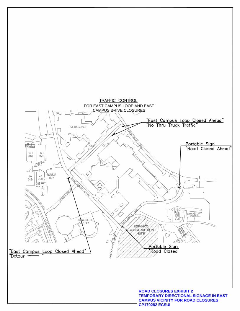
ROAD CLOSURES EXHIBIT 2TEMPORARY DIRECTIONAL SIGNAGE IN EASTCAMPUS VICINITY FOR ROAD CLOSURESCP170282 ECSUI
ECPGFC1CONSTRUCTION
SITE
EA
ST
CA
MP
US
DR
IVE
FOR EAST CAMPUS LOOP AND EASTCAMPUS DRIVE CLOSURES

SUBSURFACE INVESTIGATION, SOIL ANALYSISand
FOUNDATION DESIGN RECOMMENDATIONSfor
EAST CAMPUSPLANT GROWTH FACILITY COMPLEX
COLUMBIA, MISSOURI
Prepared for
MR. JUDE WAWRZYNIAK, AlAUNIVERSITY OF MISSOURI
GENERAL SERVICES BUILDINGCOLUMBIA, MISSOURI
Prepared by
ENGINEERING SURVEYS & SERVICES1113 FAY STREET
COLUMBIA, MISSOURI 65201
Missouri Engineering Corporation Number 2004005018
NOVEMBER23, 2016

Engineering Surveys and ServicesConsulting Engineers. Scientists, and Land Surveyors
Analytical and Materials Laboratories
1113 Fay Street E-Mail essQIESS-lnc.cornColumbia, Missouri 65201 http://www.ESS-InccomTelephone 573-449-2646Facsimile 573-499-1499
November 23, 2016
Mr. Jude Wawrzyniak. AlAUniversity of MissouriGeneral Services BuildingColumbia, MO 65211
RE: Geotechnical EngineeringEast CampusPlant Growth Facility ComplexCP170281Columbia, Missouri
Dear Mr. Wawrzyniak:
We have conducted a subsurface investigation and evaluated subsurface conditions forthe referenced project. The following report includes the results of the investigation andevaluation and our recommendations regarding foundation design and constructionconsiderations.
We appreciate the opportunity to assist you on this project and anticipate inquiriesduring the design phase. We stand ready to assist during the design phase and throughconstruction with a full range of construction oriented engineering, surveying, and laboratoryservices. If we can be of further assistance, please do not hesitate to contact us.
..çRandaIl A. Lee, P.C., R.G..q\
Reviewed by,
Joshua D. Lehmen, P.E.
Other Otl5cesJefFerson City, Missouri Sedalia, Missouri
— . LIIl\il N ‘ *—pt.
-NLlflhr:-.-— C ., Pt .-ul1i ..
_, S7 ..-
Sp, 0NAL V11111 I It4
Geotechnical Site InvestigationEast Campus Plant Growth FacilityColumbia, MissouriNovember 23, 2016
TABLE OF CONTENTS
TABLE OF CONTENTS I
1 EXECUTIVE SUMMARY 1
2 PROJECT SCOPE 2
3 DESCRIPTION OF THE SITE AND PROJECT 3
3.1 Site Location 3
3.2 Project Description 3
3.3 Site Description, Topography, and Drainage 3
4 VICINITY MAPS 4
S GEOLOGYOFAREA S
5.1 General 5
5.2 bess S
5.3 Pleistocene Glacial Deposits S
5.4 PennsylvanIan Deposits S
5.5 Mississippian Limestone and Dolomite 5
6 FIELD INVESTIGATION 6
6.1 Drilling 6
6.2 Field Tests and Measurements 6
7 LABORATORY INVESTIGATION 6
B SUBSURFACE CONDITIONS 7
8.1 General 7
8.2 Description of Subsurface Materials 7
8.3 Utilities 8
9 ENGINEERING ANALYSIS AND RECOMMENDATIONS 8
9.1 General 8
9.2 Groundwater 8
Geotechnical Site InvestigationEast Campus Plant Growth FacilityColumbia, MissouriNovember 23, 2016
9.3 Seismic Loading 8
9.4 Site Grading 9
9.5 Foundation Recommendations 99.5.1 Deep Foundations 109.5.2 Intermediate Foundations with a Slab-on-Grade 119.5.3 Shallow Foundations with a Slab-on-Grade 12
9.5.4 Incidental Foundations 12
9.6 Retaining Walls 12
9.7 Floor Slab Design 13
9.8 Pavement Design and Recommendations 14
10 CONSTRUCTION CONSIDERATIONS 15
10.1 Site Preparation 15
10.2 Site Excavation 15
10.3 Slab Subgrade Preparation 15
10.4 Foundation Excavation and Construction 15
10.5 Construction Fill and Backfill 15
10.6 Drilled Pier Construction 16
iO.7 Climatic Considerations 17
11 WARRANTIES AND LIMITATIONS 17
12 APPENDIX A 19
12.1 Symbols and Terms 20
12.2 Summary of Laboratory Test Results 21
12.3 Plan of Boring Locations 23
12.4 Boring Logs 24
13 APPENDIX B 44
13.1 2004 Boring - B3 45
II

Geotechnical Site InvestigationEast Campus Plant Growth FacilityColumbia, MissouriNovember 23, 2016
1 EXECUTIVE SUMMARY
An exploration of subsurface Conditions has been conducted for the proposed East Campus PlantGrowth Facility on the campus of The University of Missouri in Columbia, Missouri. The proposedproject consists of two phases. The first phase involves the construction of two free standing slab—on-grade greenhouses with a connecting head structure and a controlled environment building. Thesecond phase, which will be located south of the controlled environment building, will consist of threeadditional larger greenhouse structures. This investigation only encompasses the Phase 1 area andstructures. The Phase 2 structures will be addressed in a future separate report.
The two northern Phase 1 greenhouse structures are approximately 100 by 140 feet in plan andconnected by a head structure, 90 by 30 feet, containing mechanical and water distribution systems.Exterior will be steel framed with glass walls for the greenhouses and wooden construction for the headstructures. Finished floor elevations are estimated to be around ±735 feet for the greenhouses. It isanticipated that the structures will bear on strip footings with wall loads not to exceed 2,000 pounds perlinear foot.
The controlled environment building will be considerably larger at about 160 by 200 feet in plan andlocated south of the northern greenhouses. Construction may consist of a steel framed structure orconcrete masonry units with steel joists. The structure will have high walls and may contain amezzanine area. Column and wall loads are expected to range from 75 to 150 kips for the columns and2 to 3 kips for the wall, depending on the bay spacing. Finished floor elevation is estimated to be around±738 feet for the controlled environment building.
A total of 18 soil and rock borings were drilled and 2 test pits were excavated for this investigation.Fifteen of the borings and both test pits were performed within the footprints of the proposedstructures and three (BlO, BiS and Big) were drilled for utilities. We have also included a copy ofboring B3 from the preliminary geotechnical investigation for the University Parking Structure #7 whichwas located at the southwest corner of the proposed controlled environment building.
The borings indicate that the subsurface profile of this site is highly variable. A review of historic aerialphotographs and topographic surveys indicated the project lies within an old ravine that extended in anorthwest/southeast direction and has since been filled. The original contours were between 685 and715 feet the boring logs and historic topographic information indicate fill depths ranging from 13 to 45feet in borings B2 and B20, respectively. The current topography runs between 735 and 741 feet. Thefill consisted of clay rich soils with varying amounts of topsoil, brick, concrete, wood, aggregate,boulders and other construction and deleterious material. Groundwater was encountered in all but 4 ofthe borings and test pits at depths ranging from 3.5 to 40 feet and is associated with voids in the fill andthe fill/native soil surface. Groundwater is expected to influence the construction of the foundationsystem and should be planned for accordingly.
The foundation systems for the structures will in part be based on the amount of risk that the Universityis willing to accept. Recommendations for shallow, intermediate and deep foundations are presented inthis report. Discussions with representatives from both Geo-Piers© and vibratory stone columns
1

Geotechnical Site InvestigationEast Campus Plant Growth FacilityColumbia, MissouriNovember 23, 2016 —
contractor5 were mixed on their viability; however, the option is presented should the design team wishto pursue it further.
A deep foundation system would provide minimal risk to the University. Foundations bearing onPennsylvanian age shales or limestone may be proportioned for a net allowable bearing pressure of 20kips per square foot (ksf). A skin resistance of 15, psi may be used for the Pennsylvanian age limestonesand shale. Total settlement should be less than one-half inch. Considerable rock excavation isanticipated with this option.
If the University is willing to accept a higher risk, shallow foundations bearing on either an intermediatefoundation system of stone columns or engineered fill may be used. Foundations bearing on anintermediate foundation system would minimize the risk. The bearing capacity and settlement for astone column system would be provided by the specialty contractor.
Shallow foundations bearing on engineered fill should be sized for a net allowable bearing capacity of1,500 pounds per square foot (psf). Although the soils appear suitable for 1,500 psf bearing capacity,settlement cannot be determined due to the nature of the highly variable fill soils. Undercutting the fillunder the footings and replacing it with controlled engineered fill could help minimize the potentialsettlement. This option is not recommended for the controlled environment building. Additional detailsare discussed later in this report.
The exploration and analysis of the foundation conditions are considered to be in sufficient detail andscope to form a reasonable basis for design. The recommendations submitted are based on the resultsof our geotechnical investigation and analysis, and the preliminary design concepts provided by Ms. JillWalker, PE with David Mason & Associates in St. Louis, Missouri.
This summary should be used in combination with the complete report for design considerations.Additional information and details on the investigation and recommendations, not mentioned in thissummary, are contained within the report.
2 PROJECT SCOPE
The scope of the investigation included a reconnaissance of the site, a review of all available subsurfacedata in the vicinity, a subsurface investigation consisting of 18 soil and rock borings and 2 test pits todepths ranging from 10 to 53 feet, laboratory soil testing, and an engineering analysis and evaluation ofthe foundation materials present at the site.
The purpose of the investigation was to determine the types of subsurface materials present at the sitelikely to be encountered or affected by the proposed construction; to determine the general engineeringcharacteristics of the various materials; to determine the seismic site class according to the 2015International Building Codes; and to provide a basis for recommendations regarding bearing capacityand compressibility of the foundation and subgrade materials.
2

Geotechnical Site InvestigationEast Campus Plant Growth FacilityColumbia, MissouriNovember 23, 2016
3 DESCRIPTION OF THE SITE AND PROJECT
3.1 SITE LOCATIONThe site of East Campus Plant Growth Facility is located in the eastern side of the campus of TheUniversity of Missouri in Columbia, Missouri. The site is bordered to the north by East Park Loop andthe Animal Resource Center, to the west by East Campus Drive, to the south by student parking and tothe east by an undeveloped ravine and parking. Specifically, the project is located in the southwest 1/4of Section 18, Township 48 North, Range 12 West (See Vicinity Map, page 4).
3.2 PROJECT DESCRIPTION
The proposed project consists of two phases. The first phase involves the Construction of two freestanding slab—on-grade greenhouses with a connecting head structure and a controlled environmentbuilding. The second phase which will be located south of the controlled environment building willconsist of three additional larger greenhouse structures to be built at some future date and addressed ina separate future geotechnical investigation.
The two northern Phase 1 greenhouse structures are approximately 100 by 140 feet in plan andconnected by a head structure, 90 by 30 feet, containing mechanical and water distribution systems.Exterior will be steel framed with glass walls for the greenhouses and wooden construction for theheads structure. Finished floor elevations are estimated to be around ±735 feet. It is anticipated thatthe structures will bear on strip footings with wall loads not to exceed 2,000 pounds per linear foot.
The controlled environment building will be considerably larger at about 160 by 200 feet in plan andlocated south of the northern greenhouses. Construction may consist of a steel framed structure orconcrete masonry units with steel joists. The structure will have high walls and may contain amezzanine area. Column and wall loads are expected to range from 75 to 150 kips for the columns and2 to 3 kips for the wall, depending on the bay spacing. Finished floor elevation is estimated to be around±738 feet for the controlled environment building.
3.3 SITE DESCRIPTION, TOPOGRAPHY, AND DRAINAGEThe project site has been highly modified by man. The site lies in what was once a large ravine withnative ground elevations ranging from around 685 feet around boring B20 to 715 feet in the vicinity ofboring 82. The current topography runs between 735 and 741 feet. Historic aerial photographs indicatethat, between 1968 and 1977, fill consisting of clay rich soils with varying amounts of topsoil, brick,concrete, wood, aggregate, boulders and other construction and deleterious material was starting to beplaced in an uncontrolled manner. Fill had been placed in the project area as late as 1994 and in thegeneral area as late as 2011. The site is currently being used as a parking lot.
The site can best be described as slightly sloping to the southeast, with minor variations in elevation.The nearby ground surface declines gently toward the east. There is approximately 6 feet of verticalrelief across the building pad for the controlled environment building and 11 feet across the site, Sitedrainage is handled by infiltration in the landscape areas and runoff to the east.
3

Geotechnical Site InvestigationEast Campus Plant Growth FacilityColumbia, MissouriNovember 23, 2016
4 VicINITY MAPS
r Agv(
-,
I I ‘-
ç D SITE 11 !
I/1 I I
/‘,1 J/ I
-
7J’ - /‘
/ N kN:;1c* ?,
\(-- -L
Plate 1
Plate 2Pre-Fill Contours
4

aGeotechnical Site InvestigationEast Campus Plant Growth FacilityColumbia, Missouri .
November 23, 2016
5 GEOLOGY OF AREA
5.1 GENERAL
Columbia, Missouri is located near the northern terminus of the Ozark Highland Landform and is in theCentral Missouri Hills Subsection. The geology of the area is characterized by dissected Pleistocene ageglacial drift that unconformably overlays Pennsylvanian aged limestone and shale and/or Mississippianaged limestone.
5.2 LOESS
Loess is a windblown soil with variable proportions of clay, silt and fine sand. Shear strength andcompressibility of bess is generally low to moderate, but may vary dependent upon site specificconditions. A clayey silt to silty clay blanketed Boone County at one time. This material is readilyerodible and appears to have been removed from this project site.
5.3 PLEISTOCENE GLACIAL DEPOSITS
Almost all of Boone County was covered by glacial material at one time. Glacial till is typically silty orsandy clay with a fine sand grit to boulder sized inclusions in the soil matrix. Pockets or “lenses” ofnearly clean sand may also be found in this till. These soils are typically moderately to highly overconsolidated and exhibit high shear strengths and low compressibility characteristics under low tomoderate foundation loads. Glacial till underlies the entire project area and was encountered in boringswhere it had not been removed during previous construction.
5.4 PENNSYLVANIAN DEPOSITS
Pennsylvanian age material composed primarily of shale with some minor limestone and sandstoneoccur erratically throughout the Columbia area. The deposits appear commonly in filled depressionsand sinkholes that occur in the underlying Mississippian surface. Thin limestones and shale that containsome chert boulders are Pennsylvanian in age. This material was encountered in most of the boreholesdrilled for this investigation.
5.5 MISSISSIPPIAN LIMESTONE AND DOLOMITE
Most of Boone County is underlain by the Mississippian age Burlington formation. The Burlingtonformation consists of a fairly coarse-grained, massive, clastic limestone. The upper portion is commonlywhite to light gray or buff in color and is characterized by an abundance of chert which is morepronounced in the upper level. This formation typically exhibits high shear strength and lowcompressibility characteristics. The Burlington formation can be heavily characterized by karst features,including pinnacles, caves, sinkholes, and filled sinks. A review of the maps on the Missouri Center for
Applied Research and Environmental Systems does not indicate any sinkhole activity within a 1 mileradius. None of the borings were extended to this material.
5

Geotechnical Site InvestigationEast Campus Plant Growth FacilityColumbia, MissouriNovember 23, 2016
Future sinkhole activity is difficult to predict. Sinkholes and caves in this area are in various stages ofdevelopment and can appear at any time. Activities of man, both on the site and off, can alter surfacedrainage and other site conditions. These activities could accelerate the development of caves andsinkholes in areas with no evidence of this activity.
6 FIELD INVESTIGATION
Field investigations consisting of a site reconnaissance, a review of subsurface records for the area andthe drilling of 18 soil and rock borings and 2 test pits were performed on November 2nd — 4th 2016. Thefield investigation and the site reconnaissance were performed in accordance with procedures outlinedin ASTM D420.
6.1 DRILLING
Eighteen borings were advanced to depths ranging from 25 to 53 feet for this investigation. The twotest pits ranged from 10 to 12 feet in depth. All drilling was powered with a track mounted drill rig usinga carbide tipped finger bit. The test pits were excavated with a CASE Extenda-hoe. Boring and test pitlocations are shown on the Plan of Boring Locations, included in the Appendix of this report. Disturbedsamples were obtained from auger cuttings or using a split-barrel sampler in accordance with ASTMD1586. Undisturbed samples were obtained using 3-inch O.D. thin-walled sampling procedures inaccordance with ASTM D1587.
Drilling was monitored by an engineer from this firm. The engineer provided technical direction, loggedthe borings, performed field tests, and prepared and transported the samples to the laboratory fortesting.
6.2 FIELD TESTS AND MEASUREMENTS
Boring locations were selected by and based on a preliminary site plan prepared by David Mason &Associated, St. Louis, Missouri. Boring elevations were determined and locations staked by a surveycrew from this firm. The elevations are assumed correct to within ± 0.2 feet. Field observations aredetailed in the boring logs included in the Appendix of this report.
7 LABORATORY INVESTIGATION
In conjunction with the field investigation, a laboratory investigation was conducted on the sampledmaterials to determine the engineering properties needed to analyze and predict foundation andsubgrade performance. The laboratory investigation included supplementary visual classification, watercontent tests, unconfined compressive strength tests, dry unit weight measurements and Atterberg limittests. All tests were performed by this firm in accordance with appropriate ASTM procedures in aUSACE Validated Lab. Results may be found in the Appendix of this report.
Laboratory tests performed on soil samples retrieved during the field investigation provided a widerange of results which was to be expected due to the nature of the uncontrolled fill. The moisture
6

Geotechnical Site InvestigationEast Campus Plant Growth FacilityColumbia, MissouriNovember 23, 2016
contents of the soils (ASTM D 2216) were found to range from 12 to 30 percent. The dry density of theundisturbed samples ranged from 100 to 114 pounds per cubic foot (pcf). The cohesion, as measured inthe unconfined compression test (ASTM D 2166), was found to range from a low of 0.3 tons per squarefoot (tsf) to a high of 1.2 tsf. The Atterberg liquid limits (ASTM D 4318) ranged from 38 to 43 percentwhile the plastic limits ranged from 14 to 17 percent, giving plasticity indices from 23 to 28. Thisindicates the tested soils have a moderate plasticity.
S SUBSURFACE CONDITIONS
8.1 GENERAL
The materials encountered during the subsurface investigation were visually classified according toASTM D2488. The materials encountered during the field investigation are described in detail in BoringLogs included in the Appendix of this report. The stratification lines represent approximate boundaries,and the transition may be gradual.
8.2 DESCRIPTION OF SUBSURFACE MATERIALSThe subsurface conditions in the vicinity of the proposed structures were highly variable over theinvestigation site. As mentioned earlier, the project lies over an old ravine that has since been filled. Ingeneral, underlying a thin mantle chip seal or topsoil, a man-made fill consisting of clay rich soils withvarying amounts of topsoil, brick, concrete, wood, aggregate, boulders and other construction anddeleterious material all placed in an uncontrolled manner providing highly variable strengths andconsistencies, even within the same borehole. The fill was encountered in all borings and ranged inthickness from approximately 13 feet in boring B2 to 50 feet in boring B18. In test pit TP7, underlyingapproximately one foot of surface gravel and soil, concrete slabs up to 5 feet in width were encounteredthat were randomly nested on top of each other mixed with some soft wet clay. At a depth of 3.5 feet,the voids between the concrete slabs were filled with water. The concrete slabs, brick and otherconstruction debris continued until the termination of the test pit at a depth of 10 feet. The nestedconcrete slabs and voids were not observed in test pit TP17. Test pits TP7 and TP17 and boring B14were terminated in this stratum.
Native clay soils were encountered in borings B2, B4, BS, B8, BlO and B15, beneath the man-made fill, atdepths ranging from 13 to 35 feet below existing grade. Native soils may have been encountered inseveral of the other borings but were difficult to distinguish due to the presence of water and drillingmethods. The native clay soils were described as brown to orangish or light brown and gray in color,moist, firm to stiff in consistency and contained some sand and gravel. Where encountered, thicknessof the stratum ranged between 3 and 15 feet.
Beneath the native soils or fill in the remaining borings, limestone bedrock was encountered. Drillingwas terminated at auger refusal on limestone in all of the borings except B14, TP7 and TP17 atelevations ranging between the elevations of 683 and 711 feet.
7
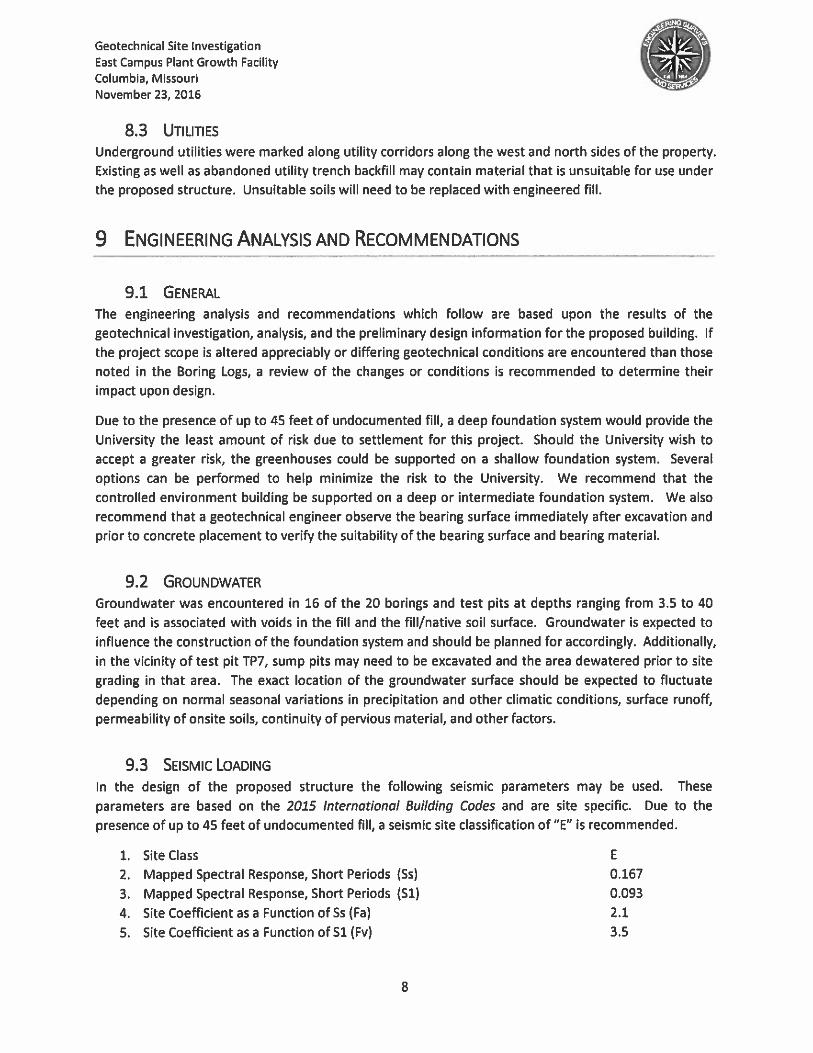
Geotechnical Site InvestigationEast Campus Plant Growth FacilityColumbia, Missouri --
November 23, 2016
8.3 UTILITIESUnderground utilities were marked along utility corridors along the west and north side5 of the property.Existing as well as abandoned utility trench backfill may contain material that is unsuitable for use underthe proposed structure. Unsuitable soils will need to be replaced with engineered fill.
9 ENGINEERING ANALYSIS AND RECOMMENDATIONS
9.1 GENERAL
The engineering analysis and recommendations which follow are based upon the results of thegeotechnical investigation, analysis, and the preliminary design information for the proposed building. Ifthe project scope is altered appreciably or differing geotechnical conditions are encountered than thosenoted in the Boring Logs, a review of the changes or conditions is recommended to determine theirimpact upon design.
Due to the presence of up to 45 feet of undocumented fill, a deep foundation system would provide theUniversity the least amount of risk due to settlement for this project. Should the University wish toaccept a greater risk, the greenhouses could be supported on a shallow foundation system. Severaloptions can be performed to help minimize the risk to the University. We recommend that thecontrolled environment building be supported on a deep or intermediate foundation system. We alsorecommend that a geotechnical engineer observe the bearing surface immediately after excavation andprior to concrete placement to verify the suitability of the bearing surface and bearing material.
9.2 GROUNDWATERGroundwater was encountered in 16 of the 20 borings and test pits at depths ranging from 3.5 to 40feet and is associated with voids in the fill and the fill/native soil surface. Groundwater is expected toinfluence the construction of the foundation system and should be planned for accordingly. Additionally,in the vicinity of test pit TP7, sump pits may need to be excavated and the area dewatered prior to sitegrading in that area. The exact location of the groundwater surface should be expected to fluctuate
depending on normal seasonal variations in precipitation and other climatic conditions, surface runoff,permeability of onsite soils, continuity of pervious material, and other factors.
9.3 SIsrviIc LOADINGIn the design of the proposed structure the following seismic parameters may be used. These
parameters are based on the 2015 International Building Codes and are site specific. Due to thepresence of up to 45 feet of undocumented fill, a seismic site classification of “E” is recommended.
1. Site Class E
2. Mapped Spectral Response, Short Periods (Ss) 0.167
3. Mapped Spectral Response, Short Periods (Si) 0.093
4. Site Coefficient as a Function of 55 (Fa) 2.1
5. Site Coefficient as a Function of Si (Fv) 3.5
8

Geotechnical Site InvestigationEast Campus Plant Growth FacilityColumbia, MissouriNovember 23, 2016
9.4 SITE GRADING
Although the site plans has not been completed for the prolect, anticipated finished floor elevations forthe green houses is around 735 feet and for the controlled environment building, 738 feet.
Site grading will consist of up to 4 feet of fill along the eastern edge of the site, outside the existingparking lot, a one to 2 feet of cut along the western edge. We recommend that the upper 4 feet underthe building slabs, which are not within the current parking lot, consist of controlled engineered fillconsisting of imported soil or aggfregate. The current parking lot surface may remain in place.Wastelime is not recommended for use as engineered fill. Additionally, in the vicinity of test pit TP7 werecommend that the nested concrete slabs, with considerable void spaces, be removed and replacedwith controlled engineered fill. Seven to ten feet of overexcavcation from existing grade may berequired in this area. This may require dewatering of the subgrade soils with sump pits and pumps.
Engineered fill should meet the compaction requirements stated in the Construction Fill and Backfill5ection of thi5 report. Any fill placed within the upper 2 feet of subgrade, extending to 5 feet beyondthe building footprint, should consist of low volume change material. Low volume change material mayconsist of imported soils with a liquid limit less than 50 and a plasticity index less than 30 or a granularfill containing sufficient fines to exhibit a definite moisture/density relationship. Again, wastelime is notrecommended for use as engineered fill. Due to the presence of questionable construction debris andmoistures, we do not recommend the use of the existing fill as part of the engineered fill.
Construction should not begin until all cuts have been completed and fill placed within the plan area ofthe proposed structures. Prior to the start of construction, it is recommended that all vegetation beremoved from the site. Additionally, except as noted above for the vicinity around TP7, anyconstruction debris or other unsuitable material within the upper 4 feet of subgrade outside of theexisting parking lot should be removed.
Following completion of stripping and grubbing, and prior to fill placement and slab-on-gradeconstruction, it is recommended that the slab subgrade be proof-rolled with a rubber-tired piece ofconstruction equipment such as a fully loaded, tandem-axle dump truck to help identity any soft orunsuitable areas. Areas identified as unsuitable should be overexcavated and reconstructed withengineered fill.
Site grading will be dependent on weather conditions. The soils are sensitive to moisture changescaused by atmospheric conditions and precipitation. Clay and silt rich soils can be subject to high ratesof erosion and loss of shear strength with increases in moisture content. Moisture content changes canalso lead to volumetric changes in the soils. The first few inches of exposed soil will be most affected bychanging conditions. The site contractor should take steps to minimize erosion of the site followingstripping and up to establishment of ground cover or turf. Earthwork operations may be delayed byheavy precipitation at the site.
9.5 FOUNDATION RECOMMENDATIONS
The two northern Phase 1 greenhouse structures are approximately 100 by 140 feet in plan andconnected by a head structure, 90 by 30 feet, containing mechanical and water distribution systems.Exterior will be steel framed with glass walls for the greenhouses and wooden construction for the head
9

Geotechnical Site InvestigationEast Campus Plant Growth FacilityColumbia, MissouriNovember 23, 2016
structures. Finished floor elevations are estimated to be around ±735 feet. It is anticipated that thestructures will bear on strip footings with wall loads not to exceed 2,000 pounds per linear foot.
The controlled environment building will be considerably larger at about 160 by 200 feet in plan andlocated south of the northern greenhouses. Construction may consist of a steel framed structure orconcrete masonry units with steel joists. The structure will have high walls and may contain amezzanine area. Column and wall loads are expected to range from 75 to 150 kips for the columns and2 to 3 kips for the wall, depending on the bay spacing. Finished floor elevation is estimated to be around±738 feet for the controlled environment building.
A perimeter foundation drainage system at the base of the exterior grade beams is recommended todischarge accumulated moisture away from the structure. The perimeter drainage system shouldconsist of a perforated pipe bedded and backfilled with free draining aggregate. The free drainingaggregate zone should be wrapped in geotextile filter fabric with an apparent opening size (ASTM 04751) of 70 to 100 and minimum trapezoid tear strength (ASTM D 4533) of 50 pounds. The free drainingaggregate should be covered with at least 2 feet of compacted low permeability clay soil. Downspoutsand gutters should not be designed to flow into the foundation drain system.
Trees or other vegetation whose root systems have the ability to remove excessive moisture from thesubgrade and foundation soils should not be planted next to the structures.
9.5.1 Deep FoundationsSeveral deep foundation systems were considered for this project, however when considering thenature of the existing undocumented fill, a drilled shaft system is considered the best viable option fordeep foundations. Due to the anticipated column loads and subsurface profile, drilled piers bearing onPennsylvanian age shale and limestone are recommended.
The following parameters should be used in the development of this deep foundation system.
DESIGN PARAMETER ALLOWABLE DESIGN VALUE
1. Skin friction in Pennsylvanian Shale & Limestone 15 psi2. End bearing Pennsylvanian Shale & Limestone 20 ksf
Due to presence of boulders, concrete and other construction debris, straight shafts are recommendedto support the proposed structure. Shaft lengths for piers bearing on 20 ksf material would range fromapproximately 34 to 55 feet, not including any sockets, as measured from the anticipated finished firstfloor elevations.
A minimum shaft diameter of 30 inches is recommended for clean-out and inspection purposes.Settlement for this type of foundation system should be 1/2-inch or less. Test holes are not required for20 ksf or less bearing material.
Due to the nature of the subsurface soils, bearing elevation, and nature of the undocumented fill,difficult drilling conditions are expected to exist. These conditions include controlling groundwater,sloughing of sidewalls, potential presence of old foundations and large building rubble and removal of asignificant quantity of rock. Experience in this area indicates that pier drilling will require core barrels
10

Geotechnical Site InvestigationEast Campus Plant Growth FacilityColumbia, MissouriNovember 23, 2016
and rock augers to penetrate some of the concrete, boulder5 in the fill, gravelly seams in the native claysoils and the gravelly weathered crust over the Pennsylvanian age limestone and shale. It is anticipated
that an average of 8 feet of rock removal consi5ting of naturally occurring chert cobbles and boulderswill be required, besides the man-made obstacles such as concrete and large boulders, prior to reaching
the top of suitable bearing material. Rock excavation should be anticipated for most of the drilled shaftlength due to the nature of the undocumented fill. A generous rock allowance should be included in thecontract documents. Any rock socket will be an additional amount of rock removal. Due to thegroundwater encountered, casing will be required on location.
9.5.2 Intermediate Foundations with a Slab-on-GradeShould the University wish to accept a greater risk of building settlement, a viable option for theproposed structure is the improvement of the fill and weak soils through the installation of stonecolumns, commercially known as Geopiers© or vibro-piles. These methods involve the excavation of acylindrical hole, typically 18-36 inches in diameter. The hole is then refilled with thin lifts (12 inches orless) of well-graded granular material, with each lift compacted with the tamper or vibrated into the
surrounding soils to induce horizontal stress on the surrounding weak soils, effectively causing theiroverconsolidation. Due to the nature of the undocumented fill, it is anticipated that the stone columnholes would need to be pre-drilled and that some coring to penetrate concrete slabs and boulders maybe required to achieve design depth. The surrounding overconsolidated soils and the stone column canbe considered to act as one stiff matrix with an improved bearing capacity from the soil alone. Shallowfoundations can bear on the stone column/soil matrix with a preliminarily estimated composite bearingcapacity of approximately 2,000 psf, however the final value would be provided by the specialtycontractor. To minimize the risk to the University, we recommend a lower bearing capacity to minimize
the additional pressure placed on the lower existing unimproved fill soils. Additionally, we recommendthat the subsurface soils be improved to a minimum of 2 times the isolated column footing width or 4.5times the continuous footing width below the base of the footing.
Should a stone column foundation system be chosen for this structure, the specialty contractor willprovide final design parameters and construction details. The specialty contractor should be madeaware of the existing undocumented fill and the probability of encountering of concrete slabs, brick andboulders that may affect the construction of the foundation system. The structural engineer shouldalso review the number of structural elements each type of system requires since the number may differfor alternate systems.
Total settlement of the stone column foundation system is expected to be in the order of one inch or
less, although final settlement calculations will be provided by the specialty contractor. Settlement is
expected to occur during construction and is related to both the composite stiffness modulus of the
stone column/soil matrix and the consolidation characteristics of the unimproved material below the
stone columns.
To minimize the effect of seasonal moisture variations, provide frost protection, and improve
performance, shallow foundations should be constructed such that the stone column/soil matrix bearing
surface is a minimum of 36 inches below the adjacent exterior finish grade.
11

Geotechnical Site InvestigationEast Campus Plant Growth FacilityColumbia, MissouriNovember 23, 2016
9.5.3 Shallow Foundations with a Slab-on-GradeShould the University wish to accept an even greater risk and that the site grading recommendationsprovided above have been performed, the two greenhouses and head structures can be supported on ashallow foundation system. We still, recommend that the controlled environment building, with itsheavier loads, be supported on either a deep or intermediate foundation system.
A shallow foundation system bearing on engineered fill can be designed for an allowable bearingcapacity of 1,500 psf. To help minimize the effects of the underlying uncontrolled fill and the potentialfor settlement, we recommend that the subgrade soils to a depth of 5 feet for isolated or 2 times thefooting width for continuous or strip footings, beneath the bearing surface and to a width of 2.5 feetpast the edge of the footing be replaced with controlled engineered fill consisting of MoDOT 1007Typel/5 aggregate base. Wastelime is not recommended for use as engineered fill. Because if thevariable nature of the uncontrolled fill, settlement estimates are not accurate; however we anticipate itto be between one to 2 inches. The lower bearing capacity is to minimize the load increase on theuncontrolled fill beneath the footings thus limiting the potential settlement.
To minimize the effect of seasonal moisture variations, provide frost protection, and improveperformance, shallow foundations should be constructed such that the stone column/soil matrix bearingsurface is a minimum of 36 inches below the adjacent exterior finish grade.
9.5.4 Incidental FoundationsIncidental shallow foundations for signs or small walls should be proportioned for an allowable bearingpressure of 1,500 psf if bearing on existing or engineered fill. To minimize the effect of seasonalmoisture variations, provide frost protection, and improve performance, auxiliary foundations should beconstructed such that the bearing surface is a minimum of 36 inches below the exterior finish grade.Settlement should be less than one inch.
9-6 RETAINING WALLS
Any walls subject to unbalanced earth pressure such as basement and retaining walls should bedesigned for earth pressures equal to or greater than those provided on the following table. For thegranular or cohesionless backfill values to be valid the “Structural Backfill” zone must extend 45° fromvertical from the heel of the retaining structure’s foundation. These load distributions do not include afactor of safety or include the influence of hydrostatic pressures on the wall. Surcharge loads above thetop of the wall due to vehicles, equipment, structures, or sloped backfill should be considered in thedesign as well.
The following chart is based on these conditions.
• Equivalent Fluid Pressures are based on a unit soil weight of 120 pcf and a cohesionless oraggregate unit weight of 140 pcf.
• No groundwater is acting on the wall.
• For active earth pressure, wall must rotate at base, top lateral movement should be between0.002 and 0.004 times the height of the wall (H).
12

Geotechnical Site InvestigationEast Campus Plant Growth FacilityColumbia, MissouriNovember 23, 2016
• Surcharge pressure (5) acts at H/2 above the base.
• Backfill is compacted to a minimum of 95% of Maximum Dry Density (ASTM D698).
• Ignore passive pressure in the frost zone.
EARTH PRESSURE COEFFICIENTS
Earth Coefficient for Equivalent Surcharge EarthPressure Backfill Type Fluid Pressure Pressure PressureConditions (psfl P1 P2
(psfl (psf)Active (K,) Cohesionless or Granular — 0.30 42 (0.30)S (42)H
Low Plasticity Clays (LL<50) — 0.42 50 (0.42)5 (50)HHigh Plasticity Clays (LL?50) — 0.52 60 (0.52)5 (60)H
At-Rest (K0) Cohesionless or Granular — 0.46 65 (0.46)S (65)1-iLow Plasticity Clays (LL’cSO) — 0.59 70 (0.59)S (70)HHigh Plasticity Clays (LL?S0) — 0.69 82 (0.69)5 (82)H
Passive (l<) Cohesionless or Granular — 3.4 475Low Plasticity Clays (LL<50) — 2.4 285 —-
High Plasticity Clays (LL50) — 1.9 230
placed engineered fill soils. A
Shallow temporary below grade excavations should bethe foundation and walls of the proposed structure.shored in accordance with OSHA guidelines. Somefreeze/thaw cycles. Long term excavation slopes andconstruction to insure that adequate stability is achieved.
9.7 FLOOR SLAB DESIGN
stable long enough to allow for construction ofAll excavations should be benched, sloped orsloughing may occur due to weathering anddeep excavations should be analyzed prior to
As mentioned earlier, should the existing undocumented fill in the parking lot remain in place and theupper 4 feet of the areas outside the existing lots consist of engineered fill according to therecommendations presented in the site grading section, slabs-on-grades may be designed using amodulus of subgrade of 100 pounds per cubic inch (pci). We recommend that the floor slab thickness bea minimum of S inches and that the slab subgrade include a capillary break (3/4” to 1” “clean”aggregate) that is a minimum of 6 inches thick. A minimum 6 mil thickness polyethylene vapor barriershould be installed beneath the slab to improve its performance. In addition, it is recommended thatthe slab be reinforced with a minimum of 6 by 6-inch woven wire mesh. Final design thickness andreinforcing shall be provided by the structural engineer.
Prior to placement of the drainage layer of aggregate and if a cohesive soil is used for the slab subgrade,the upper 8 inches of the entire slab soil subgrade should be scarified, moisture conditioned to within 0to +4 percent of optimum moisture content and recompacted as engineered fill. The drainageaggregate should be compacted by a vibratory plate or smooth roller when placed.
A maximum toe pressure of 1,500 psf may be used for design on properlycoefficient of friction 0.3 may be used to calculate sliding resistance.
13

Geotechnical Site InvestigationEast Campus Plant Growth FacilityColumbia, MissouriNovember 23, 2016
Construction and saw joints are recommended for all slabs-on-grade. Saw and construction jointsshould be installed 5uch that the panels are nearly square but do not exceed a length to width ratio of1.4 to 1.0. Maximum panel size depends on several factors including the amount of cement in the mix,the maximum coarse aggregate size, and slab thickness.
Several precautions are normally used to insure adequate long-term performance of the slab on grade.These precautions include the installation of a precipitation removal system involving the use of gutters,downspouts, and landscaping; not allowing water to pond next to the proposed structure during or afterconstruction; and not allowing the subgrade soil to become inundated or desiccated prior to or duringthe time required for construction of the floor slab.
9.2 PAVEMENT DESIGN AND RECOMMENDATIONSThe pavement associated with the project is expected to be parking area for cars and light trucks andmay also contain a trash collection area. Because trash collection areas carry heavier vehicles, it isrecommended that the pavement in these areas be designed to be more durable than the pavement inthe parking areas. It is preferred that trash collection areas (heavy duty pavement) be constructed withPortland cement concrete. Recommendations for both asphalt and Portland concrete are provided.Rigid pavements should be reinforced, at a minimum, with 6 by 6-inch welded wire fabric and 1/2-inchepoxy coated dowel bars for transverse joints.
The following pavement design recommendation has taken into account site specific traffic estimates,geotechnical information, and subgrade modification or reinforcement. A California Bearing Ratio (CBR)value of 3 was used to develop the following pavement design recommendations for the parking lot.
HEAVY DUTY
Portland Cement Concrete8” Portland Cement Concrete (4,000 psi mix)6’ M0DOT Type 1 crushed stone base
Asphaltic Cement Concrete
2” Type ‘BP-2 Asphaltic Concrete Surface Course5’ M0DOT Plant Mix Bituminous Course7’ MoDOT Type 1 crushed stone base
STANDARD DUTY
Portland Cement Concrete411 Portland Cement Concrete (4,000 psi mix)6’ M0DOT Type 1 crushed stone base
Asphaltic Cement Concrete2” Type ‘BP-2 Asphaltic Concrete Surface Course2” MoDOT Plant Mix Bituminous Course6” M0DOT Type 1 crushed stone base
14

Geotechnical Site InvestigationEast Campus Plant Growth FacilityColumbia, MissouriNovember 23, 2016
10 CONSTRUCTION CONSIDERATIONS
10.1 SITE PREPARATION
Site preparation will require stripping and grubbing and pavement demolition. All utility trenchesshould be backfilled in accordance with appropriate controlled engineered fill specifications. All trenchexcavations should be made with sufficient working space to permit the placing, inspection, andcompletion of all work including backfill construction. It is recommended that a representative of thegeotechnical engineer be present during fill placement and compaction to assure that adequatecompaction is achieved and that proper methods are employed.
10.2 SITE EXCAVATION
General site excavation may be accomplished using earthwork equipment such as dozers, trackhoes andscrapers. It is recommended that a unit price for debris and rock removal be established in the contractdocuments, to address the presence of debris cells that may be encountered.
In areas where the excavation side wall cannot be sloped to meet OSHA requirements, some form ofshoring system will be required. Shoring systems may consist of trench boxes, soldier piles and laggingand sheet piles. The same design parameters presented in the retaining wall section may be used fordesign of the shoring system.
10.3 SLAB SUBGRADE PREPARATION
The subgrade soils should not be permitted to dry excessively or become inundated prior to or duringconstruction of the floor slab. If subgrade soils are found to be unsuitable or become disturbed bynature or construction activities, these areas should be excavated to a solid base and then regraded withcontrolled engineered fill.
10.4 FOUNDATION EXCAVATION AND CONSTRUCTIONFoundation bearing surfaces should be free of loose soil and standing water, and should be level.Foundation concrete should be placed the same day the foundation is excavated. Deleterious materialsor isolated soft spots within the foundation should be overexcavated to suitable base and filled todesign bearing elevation with lean concrete.
10.5 CONSTRUCTION FILL AND BACKFILL
Engineered fill is defined as soil or granular fill containing sufficient fines to establish a moisture/densityrelationship. Engineered fill should be free of frozen soil, organics, rubbish, large rocks, wood, or otherdeleterious material. Cohesive soils should be uniformly compacted to at least 95 percent of the“Standard” maximum dry density and be within -2 to +4 percent of optimum moisture content as
described by ASTM D698. Granular fill, such as MoDOT 1007 Type 1/5, should be compacted to at least
95% of the maximum dry density as determined by the Standard Proctor, ASTM D698. The moisture
content should be high enough to provide for proper compaction but low enough to prevent undue
15

Geotechnical Site InvestigationEast Campus Plant Growth FacilityColumbia, MissouriNovember 23, 2015
pumping. Should the results of the in-place density tests indicate that the specified compaction limitshave not been achieved, the area represented by the test should be reworked and retested as requireduntil the specified limits are reached. Proposed fill should be analyzed by the geotechnical engineer assoon as borrow sources are identified to determine suitability and conformance with the followingrecommendations.
Soil classified as MH, OH, OL, or PT (high plasticity soils and organic soils) by the Unified SoilClassification System (ASTM D 2487) should not be imported for use as engineered fill. Soils that classifyas CH should be analyzed and approved by a qualified geotechnical engineer prior to use on site.Limestone screenings or “wastelime” is not recommended for use as fill on this site.
The fill material should be placed in layers, not to exceed eight inches in loose thickness, and should bewetted or dried as required to secure specified compaction. Effective spreading equipment should beused on each lift to obtain a uniform lift thickness prior to compaction. Each layer should be uniformlycompacted by means of suitable equipment of the type required by the materials composing the fill.Material that is too wet to permit proper compaction may be stockpiled or spread and permitted to dryassisted by disking, harrowing, or pulverizing until the moisture content is reduced to a satisfactoryvalue. The fill layers should be placed in horizontal lifts. Fill placed on slopes greater than SH:1V shouldbe benched into the slope. Rocks and stones that exceed the thickness of the 8 inch loose lift layershould be removed and disposed of off the immediate construction site.
Fill and subgrade construction should not be started on foundation soil, partially completed fill, orsubgrades that contain frost or ice. Fill should not be constructed of frozen soil. Frozen soil should beremoved prior to placing fill material.
10.6 DRILLED PIER CONSTRUCtION
Difficult drilling conditions including concrete, rebar, construction debris, weak soils, boulders, fracturedrock and groundwater are expected to exist. It is recommended that a generous rock allowance beincluded in the unit prices. Groundwater is expected to influence pier construction and a casing anddewatering allowance should also be included in the unit price.
Pier shafts should be excavated within the following tolerances:
1. The shaft centerline should be within 3 inches or four percent of the shaft diameter,whichever is less.
2. The shaft diameter should not vary by more than plus three or minus one inch.
3. The shaft diameter should be plumb to within one percent of the total length, 12.5percent of the shaft diameter, or 15 inches total, whichever is less.
If loose soil, high groundwater levels, or other conditions occur which cause the sides or bottom of theexcavation to become unstable, the excavation should be advanced through a temporary casing,permanent casing, or other approved methods. Any water that enters the excavation should bepumped down to a depth of less than two inches prior to concrete placement. If any pier excavationcannot be satisfactorily dewatered, concrete should be placed using tremie techniques. Groundwater
16
Geotechnical Site InvestigationEast Campus Plant Growth FacilityColumbia, MissouriNovember 23, 2016
was encountered during drilling, therefore it is recommended that enough casing of proper size be onlocation during drilling. A temporary casing is required for all downhole inspections. Should the piers beadvanced through the existing fill, casings may need to be nested to reach suitable bearing material. Anallowance should be included in the bid documents for the additional concrete required in piersoversized for casing.
All pier concrete should preferably be placed immediately after excavation but no later than one to 2hours after excavation. Concrete may be placed in dry pier excavations with the use of a tremie or bythe free fall method; however, concrete should not be allowed to hit the side of the shaft or the rebarcage during placement.
All loose material and spoil should be removed from the shaft prior to placing concrete. In no caseshould the volume of such material exceed that which would be required to coverS percent of the shaftbase at the bearing elevation to a depth of more than 2 inches. Shafts bearing on limestone bedrockshould be excavated to a relatively level plane.
10.7 CLIMATIC CONSIDERATIONS
The on-site 5oils are relatively sensitive to changes in atmospheric conditions and precipitation. Thesesoils are predominantly clay and silt, and are subject to high rates of erosion, rapid loss of shear strengthupon wetting, and shrink-swell behavior with changes in moisture content. The greatest impact ofclimatic conditions will occur within the first few inches of exposed soil surface. The contractor shouldtake positive measures to limit erosion of the site following stripping and up to establishment of groundcover or turf. Earthwork operations may be delayed by heavy precipitation at the site.
11 WARRANTIES AND LIMITATIONS
This report has been prepared for the exclusive use of University of Missouri and their consultants forthe specific project discussed, in accordance with generally accepted soils engineering practicescommon to the east Missouri area. No other warranties, expressed or implied, are made.
This investigation and report do not constitute a guarantee of subsurface conditions, groundwaterconditions, excavation characteristics or construction conditions. We recommend that excavationconditions across the site be evaluated during construction relative to this interpretation of subsurfaceconditions. Variations in subsurface conditions may occur that require evaluation or revision ofgeotechnical design parameters or recommendations. If the scope of the project is altered or differinggeotechnical conditions are encountered, it would be advisable to review and update ourrecommendations in consideration of those findings or variations.
Recommendations contained in this report are based on subsurface conditions and proposed designsprovided as of this date. The above study and recommendations are applicable only for the conditionsand locations described, and for the specific project mentioned. Use of the data contained herein byothers may require interpretation or analysis that was not contemplated by our investigation andanalysis. The use of this data and any interpretations or conclusions developed by others are the soleresponsibility of those firms or individuals.
17

Geotechnical Site InvestigationEast Campus Plant Growth FacilityColumbia, MissouriNovember 23, 2016
Factors affecting design and construction often become apparent during detailed design or actualconstruction that were not anticipated in the pre-design or early design phases. Engineering Surveysand Services is available during design and construction to assist in evaluating these factors and theirimpact on these geotechnical recommendations.
18

Geotechnical Site InvestigationEast Campus Plant Growth FacilityColumbia, MissouriNovember 23, 2016
12 APPENDIX A
19

LAB NO. 3765SYMBOLS AND TERMS
PROJECT’ East Campus Plant Growth Facility ComplexColumbia, Missouri
SAMPLE TYPES
N NAuger Shelby Split Giddings No NX Core Roller Bit Concrete Down Hole
Tube Spoon Tube Recovery Boring (Tn—Cone) Corer Hammer
AS BR LVI ATI ON S
0 Unconfined Compression (1)
• Water Content (2)
+ Plastic (PL) & Liquid (LL) Limit (2)
USCS Unified Soil Classification System
P1 Plasticity Index
ATD At Time of Drilling
RQD Rock Quality Designation
55 Split Spoon — 1 3/8” ID., 2” O.D.
ST Shelby Tube — 3” O.D.
PA Power Auger
HA Hand Auger
AS Auger Sample
S Cuttings Sample
2 TV Hand—Held Torvane
2 DEFINITIONS
Blows per ft.— Indicates blows per 12 inches of sampler penetration when driven by a140—pound hammer falling freely 30 inches. The Standard PenetrationResistance is the number of blows for the last 12 inches of penetration ofthe split—spoon sampler.
II
lJ-J
NOTES
(1) Sheor Strength Data plotted on cohesion scale of Boring Logs.
(2) Classification and Index Properties plotted on Water Content Scale of BoringLogs.
, Engineethig Sun’eys £ ServicesColumbia. Missouri
r\C
uRE
NT
DR
AiW
NG
S\E
SSC
OL
U•’
8?\M
U\L
3765
\37
65
SO
Rt
LGG
S.D
WC
1 1/7
7/2
0!6
_______
WN
ATU
RA
LN
ATU
RA
LA
HE
RB
ER
GU
NC
ON
FIN
EDZ
ZD
EPTH
USC
SM
OIS
TUR
ED
RY
LIM
ITS
CO
MPR
ESSI
ON
PP
(FE
ET
)C
LASS
CO
NT
NT
DN
SIT
YLL
PLP1
CO
HES
ION
STR
AIN
REM
AR
KS
C)
m(Z
)(P
CF)
(TS
r)
E.
NI
81A
S1
1.o-
aoC
L18
3914
25
ST
23.
0-5.
019
W=
O.8
1st
PP
=2
8ts
f-
0S
S3
8.0-
9.5
23P
P=
13
1sf
S8
413
.0-1
4.5
25S
S5
23.0
-24.
520
to
83A
S1
1.0-
2.0
18—
•
ST
22.
5-3.
0C
L17
114
4315
281.
26.
6W
=1.1
tsf,
PP
2.3
1sf
SS
313
.0-1
4.5
20S
S4
18.5
-20.
024
85
AS
I25-4
.023
552
7.5-
9.0
26553
12.5
-14.
028
554
17.5
-19.
021
SS
522
.5-2
4.0
21
89
AS
10.
0-3.
0C
L18
4315
28S
T2
3.0-
5.0
23P
P=
2.5
1sf
t554
8.0-
9.5
25W
=0.9
Is!,
PP
=1
.81s
fS
SS
13.0
-14.
530
SS
618
.0-1
9.5
30587
28.0
-29.
525
B13
AS
I1.
0-3.
0C
L20
3615
23V
)S
T2
3.0-
3.1
1210
4S
S3
4.0-
5.5
18N
0S
S4
8.0
-.9.5
20jJ
)
ST
513
.5-1
4.0
2810
00.
310
.5W
=0
.5ts
f,P
P1
.01s
fN
586
18.0
-19.
522
PP
=1
.01s
f0
AS
722
.0-2
4.0
235
58
28.0
-29.
525
PP
=1
.01s
f

0N
AT
UR
AL
NA
TU
RA
LA
UE
RB
ER
GU
NC
ON
FIN
ED
flW
ZZ
DE
PTH
US
CS
MO
IST
UR
ED
RY
LIM
ITS
CO
MP
RE
SS
ION
P2P
(FE
ET
)C
LA
SS
CO
NT
EN
TD
EN
SIT
YLL
PL
P1C
OH
ES
ION
STR
AIN
RE
MA
RK
Sm
(%)
(PC
F)
(TS
F)
B14
ST1
3.0-
5.0
CL
1742
1725
PP
=1.
51s
f,Pp
=3.o
tsf
SS
28.
0-9.
522
W=
0.5
1sf,
PP
=1.
51s
fS
S3
13.0
-14.
523
W=
0.8
1st
PP
=1.
51s
f
916
SS
13.
0-4.
521
W=
1.1
1sf,
PP
=I.
51s
fS
T2
8.0-
9.0
19P
P=
1.5
1sf
ST
313
.0-1
3.4
1910
00.
45.
6P
P=
1.75
1sf
Z.
AS
418
.0-2
0.0
26
a91
8A
S11.
0-3.
018
SS
23.
0-4.
520
PP
=1.
0ST
38.
3-8.
822
104
0.4
6.1
W=
1.1
1sf,
PP
=2.
31s
fS
S4
13.0
-14.
529
W=
1.1
1sf,
PP
=1.
51s
fA
SS
17.0
-19.
021
SS
623
.0-2
4.5
22W
=0
.4ts
f,P
P=
1.0
1sf
920
552
3.0
4.5
20P
P=
1.5
1sf
4S
T3
8.3-
8.8
2310
40.
66.
2W
1.1
tsf,
PP
=2.
31s
f554
13.0
-14.
520
PP
1.0
1sf
SS
518
.0-1
9.5
20W
=0
.9ts
f,P
P=
1.5
1sf
856
23.0
-23.
215
887
28.0
-29.
516
(/)
<N
0
TV
=H
and
Hel
dT
orva
ne,
PP
=P
ock
etP
enet
rom
eter
“1
Max
3011
443
1728
1.2
10.5
Mm12
100
3814
230.
35.
6N
0 I

41
I—.
- r,-.- I.—
‘-“815
re,r
fl)t r7.
fl1.1
LAB NO. 3765 PLAN OF BORING LOCATIONSPROJECT: East Campus Plant Growth Facility Complex
Columbia, Missouri
1— —
— — —
200
SCALE: 1” = 100’
I(I)
• n r-Th‘ it
•p Vp— t’,_
rn,7 Ffl
,_ t-a rr-,e
LEGEND
— — —— PROPOSED BUIWING
0 EngiizeeringSunqs S SenikesColumbia, Missouri
BORING
•83 BORING — 2004
Complex TYPE: 4 Solid Stern Augerwith Finger Bit
LAB NO. 3765
PROJECT: East Campus Plant Growth FacilityColumbia, Missouri
LOG OF BORING NO. B!
firm
— Z . COHESION, TON/SQ.FT.SOIL DESCRIPTION 0.2 0.4 0.6 0.8 1.0 1.2 1.4
TYPE, COLOR, MOISTURE & OTHER -Q PLASTIC ‘ WATER LIQUID
See Plan of LIMIT CONTENL% LIMITLOCATION: Boring Locations — + . +SURF. ELEV.: 735,5’ m Ci 10 20 30 40506070
BASEROCK I
FILL; SILTY CLAY: Brown to dark gray, moist, CL -j—e—-—— —
-; dark to bluish gray, moist, firm, 4aggregate
-; considerable cobbles-; gray to dark gray, moist, firm, somesand and gravel
FILL; SILTY CLAY: Brown and gray, moist, soft 4 —
FILL; GRAVELLY CLAY: Gray to dark gray, 21 I
moist, firm, considerable chert
STONE:Weathering ,_,,,,,,,, —— — —— —- —— — - —— —
AUGER REFUSAL ON LIMESTONE
LI;
Lu
0
Is)
cc,N“,
“1
:3
N—Jcici
Lj
:3ci Completion Depth: 33.7’
Date: 3 November 2016* Eqi’neeringSun’eyc Sen/enCotumbia, Missouri
Depth to Water ATD: 13.5’

LAS NO. 3765 LOG OF BORING NO. 82
PROJEc)7 East Campus Plant Growth Facility Complex TYPE: 4” Solid Stem AugerColumbia, Missouri — —
— with Finger Bit
-. Z . COHESION, TON/SQ.FT.u_ cSOIL DESCRIPTION e< ii. 0.2 0.4 0.6 0.8 1,0 1.2 1.4
b TYPE, COLOR, MOISTURE&OTHER I I I
w 0 PLASTIC WATER LIQUIDJ -J (flZj5t— °- See Plan of ui - LIMIT CONTENTI% LIMIT
LOCATION: Boring Locations ° < — + +- -3DC U) SURF. ELEV.: 731,5’ m C 2506O70TOPSOIL: Brown to dark brown, aggregate
FILL; SILTY CLAY: Brown, moist, firm to stiff-; brownish gray to dark brown, moist,soft to firm, aggregate
-; gray to dark gray, trace of brown,moist, soft to firm, plastic)
14
5
SILTY CLAY: Light brown and gray! moist, firm 5
-; brawn and gray, moist, firm
-5-
- 10-
- 15 -
- 20-
- 25-
- 30-
- 35-
- 40—
- 45 -
- 50 -
- 55-
SILTY CLAY: Brown and gray, moist! firm
-; cobbles
AUGER REFUSAL ON LIMESTONE —
C.,0-J
-J
I,’
‘0
‘I-s
-J
Completion Depth: 29’ Depth to Water ATD: 8.0’Date: 4 November 2016* Engineering Survep £ Services
Columbia, Missouri

LAB wa 3765 LOG OF BORING NO.PROJECT- East Campus Plant Growth Facility Complex TYPE: 4 Solid Stem Auger
Columbia, Missouri — —— with Finger Bit
F- Z . COHESION, TON/SQ.FT.u QF
SOIL DESCRIPTIONQ 0< 0.2 0.4 0,6 0.8 1.0 1.2 1.4
Li TYPE, COLOR, MOISTURE&OTHER W w<)- I I I I I I I
- w °- zU PLASTIC WATER LIQUIDI -JF— - See Plan of D F— ± LIMIT CONTENT,% LIMIT°- LOCATION: Boring Locations 3 -J + +Id <0 SURF. ELEV.: 736.1’ m ioooosoo7o
CHIP SEALBASE ROCKFILL; SILTY CLAY: Grayish brown, moist, firm,aggregate
-; gray to dark gray, moist, firm to stiff,aggregate and sand-; boulder or concrete
CL 114---Sw 1
FILL; SILTY CLAY: Dark gray, moist-; gray, soft, very moist, chert gravel-; considerable gravel
• FILL; SILTY CLAY: Dark gray, moist to very 42moist, chert gravel, concrete fragments
, -; dark gray, considerable chert gravel
-5-
- 10-
- 15 -
- 20-
- 25 -
- 30-
- 35-
- 40 -
- 45-
- 50-
- 55-
LUSTONE
____ ____ ____
AUGER REFUSAL ON LIMESTONE
I.)
N
c)
--3
‘I:
-3-J
LuLu
I-’
Lu
ci
LL.
Completion Depth: 25.2’Date: 3 November 2016* Engineering Surveys Services
Columbia, Missouri
Depth to Water Alt: 70’

LOG OF BORING Na 84
TYPE’ 4” Solid Stem Augerwith Finger Bit
Z COHESION, TON/SQ.FT.Ls CSOIL DESCRIPTION o< u 0.2 0.4 0.6 0.8 1.0 1.2 1.4
I I I I I I
TYPE, COLOR, MOISTURE & OTHERPLAS11C WATER LIQUIDCIJ5
See Plan of Dc!) fr- LIMIT CONTENT,% LIMITLOCA11ON: Boring Locations 9 -j + -e +SURF. ELEV.: 733.4’ m ioooooo7o
CHIP SEAL I. — —
BASE ROCK /FILL; SILTY CLAY: Brown and gray, moist, firm 6
-;concreteslabs-; gray to dark gray, moist firm to stiff,some aggregate
FILL; SILTY CLAY: Dark gray, moist, soft, some wosandandgravel
-; cobbles
-; dark gray, concrete fragments19
-; concrete
Completion Depth: 36.5’Date: 3 November 2076
LAB NO. 3765
PROJECT: East Campus Plant Growth Facility ComplexColumbia, Missouri
SILTY CLAY: Brown
AUGER REFUSAL ON LIMESTONE
cc,.3
b
U,
L.
* Engineering Sllrveys S Sen’icesColumbia, Missouri
Depth to Water AD: 73.5’

1)
00
0
N
“1
-t
C-)
0
:1)C.)
LAB NO. 3765 LOG OF BORING NO. 85
PROJECT’ East Campus Plant Growth Facility Complex TYPE: 4” Solid Stem AugerColumbia, Missouri — — — with Finger Bit
2 . COHESION, TON/SQ.FT.FSOIL DESCRIPTION
0.2 0.4 0.6 0.8 1 0 1.2 1.4TYPE, COLOR, MOISTURE & OTHER
ww>- I I
C,,, z PLASTIC WATER LIQUIDH Q- See Plan of H th LIMIT CONTENT,% LIMIT
LOCATION: Boring Locations 0 < 2 —j + S- -D° (1 SURF. ELEV.: 730.6’ m—
JOPSOIL; Dark brownFILL; SILTY CLAY: Brown, moist
dark gray, moist, firm
-; brown and dark gray, sand pockets,very moist, soft 22 .
0
N
-5-
- 10 -
- 15 -
- 20-
- 25-
- 30-
- 35-
- 40 -
- 45 -
- 50 -
- 55 -
> FILL; SILTY CLAY: Brown, light brown and gray, 5moist, firm, some dark gray sand at 14’
. -; light gray and tan to dark gray, moist,N’ firm, some gravel
SILTY CLAY: Brown, orangish brown and gray, 8moist, stiff
; cobbles
&!STONE
____ ____ ____
_JAUGER REFUSAL ON LIMESTONE
Completion Depth: 37.8’ Depth to Water ATD: 4.0’Date: 4 November 2016* Ei:g/neen’ngSurveyc S Sers’/ces
Columbia, Missouri

Completion Depth: 277’Date: 2 November 2016
LOG OF BORING NO. B6
TYPE• 4” Solid Stem Augerwith Finger Bit
LAB NO. 3765
PROJECT’ East Campus Plant Growth Facility ComplexColumbia, Missouri
z . COHESION, TON/SQ.FT.u OF-SOIL DESCRIPTION
0< 0.2 0.4 0.6 0.8 1.0 1.2 1,4I I I I I I ITYPE, COLOR, MOISTURE & OTHER ° PLASTiC WATER LIQUIDwZi5
See Plan of ou, i— LIMIT CONTENT,% LIMITLOCATION: Boring Locations 0 < z -J + -e +
-
SURF’. ELEV.: 735,3’ ci oooooo1CHIP SEALBASE ROCKSILTY CLAY: Brown to dark gray, moist, firm,some sod
-; brown to dark gray, moist, firm to stiff,some aggregate-; chert cobbles and boulders, possibleconcrete-; chert cobbles or concrete
firm-; brownish to bluish gray, moist, soft to
-; cobbles
11
5
friable
14JFILL; SILTY CLAY: Dark gray, gray, some black,moist to very moist, trace of weatheredlimestone, some sand and gravel, somewhat
-; cobbles
AUGER REFUSAL ON LIMESTONE
0fl,
—C
Cr
a:-3
* Engineeri,igsurveyc Sen’/cesColumbia, Missouri
Depth to Water ATD: 14.0’
N
Ci
0
C)C)4)ccNN)
Cr,
C)vi
CiciS..‘it
Li
0ci
LAB NO. 3765 LOG OF BORING NO. W7
PROJECT East Campus Plant Growth Facility Complex TYPE: BackhoeColumbia, Missouri — —
F- Z COHESION, TON/SQ.FT.W LL QFa SOIL DESCRIPTION
To< ii.. 0.20.40.60.81.01.21.4
I
‘WE. COLOR, MOISTURE & OTHER o b.J PLASTIC WATER LIQUIDf -J (fl5 %%
F- 0 See Plan of F- LIMIT CONTENT,% LIMIT°- LOCA11ON: Boring Locations C < -j + -.Ifl <° SURF. ELEV.: 731.7’ ioooosoom
FILL;3” TO 4” AGGREGATE WITH FINE SAND:Gray
FILL; SILTY SANDY CLAY WITH 3” TO 4”AGGREGATE: Bricks, concrete chunks up to 5’wide, dark gray, wet, soft
-; water around concrete
IFILL; GRAVELY CLAY WITH CONCRETECHUNKS UP TO 4’ WIDE: Brick, cobble size22egate._wet, soft, water in voids
-5-
- 10-
- 15 -
- 20-
- 25-
- 30-
- 35-
- 40-
- 45-
- 50 -
- 55-
Completion Depth: 10.0’Date: 2 November 2016* Eiigineethzgsun’ej’s t Sen’/ces
Columbi a, Missouri
Depth to Water ATD: 3.5’

JOPSOH.FILL; SILTY CLAY: Brown, moist, firm
-; dark gray, moist, firm to stiff, somesand and gravel
-; dark gray, moist, soft to firm, somesand and gravel
FILL; SILTY CLAY: Brown and dark gray, moist,firm to stiff, thin wet aggregate layer at 14’
-; cobbles or concrete fragments
FILL; SILTY CLAY: Dark gray, concrete orcobbles and gravel
-; considerate cobbles or concretefragments
Completion Depth: 42.6’Date: 4 November 2016* Eng/neethig Sur;’ejs £ Services
Columbf a, Missouri
LAB NO, 3765 LOG OF BORING NO. 88
PROJECT: East Campus Plant Growth Facility Complex TYPE.• 4” Solid Stem AugerColumbia, Missouri — — — with Finger Bit
Z . COHESION, TON/SQ.FT.w w Oha SOIL DESCRIPTION
0< 0.2 0.4 0.6 0.8 1.0 1.2 1.4I I I Iu h- TYPE, COLOR, MOISTURE & OTHER °
° PLASTIC WATER LIQUIDf -i cnze— 0- See Plan of Din LIMIT CONTENT,% LIMIT0 LOCATION: Boring Locations 0 < —i + .- -I-In <0 UI SURF. ELEV.: 732.7’ ioooooow
0 4
7
-5-
- 10 -
- 15 -
- 20-
- 25-
- 30-
- 35-
- 40 -
- 45 -
- 50 -
- 55-
-; less concrete
t
SILTY CLAY: Brown, moist, cobbles
ST0NE
____ ____ ____
AUGER REFUSAL ON LIMESTONE
Depth to Water ATD: 14.0’

C)
N
-j
Completion Depth: 32.0’Date; 4 November 2016
Depth to Water ATD: 12.0’
Engineering Sun’eys Services
LAB NO. 3765
PROJECT: East Campus Plant Growth Facility Complex TYPE:Columbia, Missouri
LOG OF BORING NO. B9
4” Solid Stemwith Finger Bit
Auger
N
z . COHESION, TON/SQ.FT.SOIL DESCRIPTION
0.2 0.4 0.6 0.8 1.0 1.2 1.4TYPE, COLOR, MOISTURE & OTHER
PLASTIC WATER LIQUIDSee Plan of LIMIT CONTENT,% LIMIT
LOCATION: Boring Locations —J + +SURF. ELEV.; 731.7’ 10 20 30 40 50 60 70
FILL; SILTY SANDY CLAY: Brown, moist, firmCL [ ÷ ——J—-— +
FILL; SILTY SANDY CLAY WITH BRICK — —FRAGMENTS: Moist, firm, gray and tan — —
FILL; SILTY SANDY CLAY WITH GRAVEL:Gray and tan, firm, moist
-; brick fragments, gray, moist, firm 4 — —
-; soft, wet, dark gray1 1
FILL; SILTY CLAY: Tan and gray, some sand, 8 — —moist,firmtostiff
FILL; SILTY SANDY CLAY: Gravel and cobbles,gray, soft, wet
-; gray, soft, wet, root hairs and organics8
COBBLES —— -— —- -— —-AUGER REFUSAL ON LIMESTONE
* Columbia, Missouri

L’4
t%.
S
.1-i0
i4J
0
4
—I;
-e
-rcrj
c..
EiigineethigSurveyc ServicesColumbia, Missouri
LAS NO. 3765
PROJECT East Campus Plant Growth Facility Complex TYPE:Columbia, Missouri
LOG OF BORING NO. BlO
4” Solid Stem Augerwith Finger Bit
- Z . COHESION, TON/SQ.FT.SOIL DESCRIPTION
0.2 0.4 0.6 0.8 1.0 1.2 1.4TYPE, COLOR, MOISTURE & OTHER °
PLASTIC WATER LIQUIDSee Plan of LIMIT CONTENT,% LIMIT
LOCA]1ON: Boring Locations 9 -J -F +SURF. ELEV.: 738.0’ m 0 10 20 30 40 50 60 70
CHIPSEAL\BASE ROCK IFILL; SILTY CLAY: Brown and gray, moist, firm,some sand and aggregate
-; dark to light gray, moist, firm, friable-; concrete fragments or boulders
-; considerable cobbles or boulders
FILL; SILTY CLAY: Dark gray, trace brown, 8 — —moist, firm, some brick, some sand
-; dark gray, moist to wet, soft to firm,brick 6 —
SILTY CLAY: Brown, reddish brown, trace of 5%”
black, moist, firm to stiff —;weathered limestone — — — — — - — — —
AUGER REFUSAL ON LIMESTONE
Completion Depth: 30.2’Dote: 2 November 2016
*Depth to Woter ATD: 19.0’

-; gray, dark gray, some brown, moist,firm, some sand and gravel, brickfragments
-; dark gray, gravel, moist to very moist
-; cobble, gravel and boulders
-; dark to light gray, trace of black andblue, moist, firm, chert gravel, somesand-; cobbles
-; considerable cobbles
AUGER REFUSAL ON LIMESTONE
LAS NO. 3765PRQJECr East Campus Plant Growth Facility
Columbia, Missouri
LOG OF BORING NO. 811
Complex TYPE’4K Solid Stem Augerwith Finger Bit
F: z
SOIL DESCRIPTIONl- COHESION, TON/SQ.FT,
TYPE, COLOR, MOISTURE & OTHER0.2 0.4 0.6 0.8 tO 1.2 1.4
See Plan ofz - PLASTIC WATER LIQUIDD ‘— LIMIT CONTENT,% LIMIT
LOCATION: Boring Locations Z — + +SURF. ELEV.: 734.9’ ifi
-_
CHIP SEALASE ROCK
FILL; SILTY CLAY: Dark gray, moist, firm-; gray, dark gray and light brown, moist,firm, trace of sand and gravel
-; moist, firm
I
soft
8
11‘p
0
0
Lfl
In
tp,0
Completion Depth: 36.5’Date: 2 November 2076
Engr’neeHng Surveys S ServicesColumbia, Missouri
Depth to Water ATD: 17.0’

LOG OF BORING NO. 812
TYPE: 4” Solid Stem Augerwith Finger Bit
LAB No. 3765
PROJECT East Campus Plant Growth Facility ComplexColumbia, Missouri
j— Z . COHESION, TON/SQ.FT.b OSOIL DESCRIP]10N
0.2 0.4 0.6 0.8 1.0 1.2 1.4I I I I I
TYPE, COLOR, MOISTURE & OTHER ° PLASTIC WATER LIQUID1ZU5See Plan of u I— LIMIT CONTENT,% LIMIT
LOCA11ON: Boring Locations C < -j + -e +SURF. ELEV.: 733.0’ D
FILL; SILTY CLAY: Tan, moist, firm, some sandandgravel
SILTY CLAY: Gray, stiff to hard, moist! somesand
SANDY SILTY CLAY: Dark gray, stiff, moist-; some cobbles
7
5
5
12
-; dark gray, moist, soft to firm
-; some gravel, dark gray, moist, firm
-; some cobbles
-; dark gray, moist, firm
-; gravel, moist, firm, rock in end of splitspoon
-; cobbles
AUGER REFUSAL ON LIMESTONE
‘S
U-’
C)-J
Lj1’-0
co
In
IC
cm
1)0
cmI—
Completion Depth: 36.0’Date: 2 November 2016
* Ezgineer/ng Suricyc & Sen’ices
Depth to Water ATD: 35.0’
Columbia, Missouri
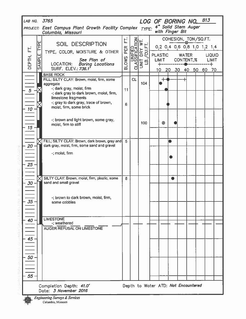
p
F Z . COHESION, TON/SQ.FT.L oF-
SOIL DESCRIPTION 0.2 04 06 0.8 10 1.2 1.4wo I ‘I
TYPE, COLOR, MOISTURE & OTHER a-° PLASTIC WATER LIQUIDwZi75
See Plan of D,j F- cii LIMIT CONTENT,% LIMITLOCA11ON: Boring Locations C < z -j + -e +
-
SURF. ELEV.: 736.1’ m C oooooowBASEROCK ——
FILL; SILTY CLAY: Brown, moist, firm, some CL -H H— —faggregate 104
-; dark gray, moist, firm 11-; dark gray to dark brown, moist, firm,limestone fragments
-; gray to dark gray, trace of brown,6
moist, firm, some brick
-; brown and light brown, some gray,moist, firm to stiff 100 ® •
FILL; SILTY CLAY: Brown, dark brown, gray and 5 — — — —dark gray, moist, firm, some sand and gravel — — — — —
-; moist, firm.
SILTY CLAY: Brown, moist, firm, plastic, some 5 — — —sand and small gravel
-; brown to dark brown, moist, firm,somecobbles
LIMESTONE_;weathered — — — —
AUGER REFUSAL ON LIMESTONE
*Completion Depth: 41.0’Dote: 3 November 2016
Depth to Water ATD: Not Encountered
LAB N 3765
PROJECT: East Campus Plant Growth FacilityColumbia, Missouri
LOG OF BORINGComplex TYPE: 4” Solid Stem
with Finger Bit
NO. BI3
Auger
N
(/
Ct0Ct
cc,N
N
Engineering Sun’ej’s ServicesColumbia, Missouri
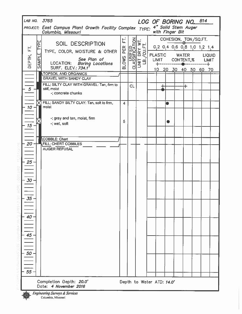
-J
‘0
* E,zg/neer/ng Siirreyc Seri’/cesColumbia, Missouri
LAB NO. 3765 LOG OF BORING NO. B14
PROJECT East Campus Plant Growth Facility Complex TE: 4” Solid Stem AugerColumbia, Missouri — —
— with Finger Bit
.2 2 . COHESION, TON/SQ.FT.wSOIL DESCRIPTIONL 0.2 0.4 0,6 0.8 1.0 1 2 1.4
W TYPE, COLOR, MOISTURE&OTHER I I I
f n a PLASTIC WATER LIQUID- 0 See Plan of u LIMIT CONTENT,% LIMIT
LOCATION: Boring Locations ° < —‘ -F +-J -‘o° SURF. ELEV.: 734.1’ W C ioooooo7oTOPSOIL AND ORGANICSGRAVEL WITA áAI’JDY CLAY
FILL; SILTY CLAY WITH GRAVEL: Tan! firm to CL + -—— ---—stilimoist—
-; concrete chunks
FILL; SANDY SILTY CLAY: Tan, soft to firm, 4 — — —moist
-; gray and tan, moist, firm
• -; wet, soft
0
N
N
COBBLE: ChertALL; CHERT COBBLES
____ ____
AUGER REFUSAL
-5-
- 10-
- 15 -
- 20-
- 25-
- 30-
- 35-
- 40-
- 45-
- 50-
- 55-
-z.
0U
-U
Completion Depth: 20.0’Date: 4 November 2016
Depth to Water ATD: 14.0’
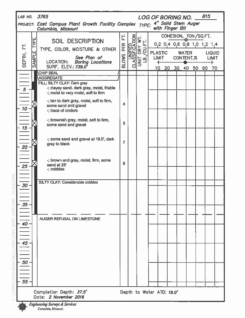
LOG OF BORING NO. 815
Complex TYPE: ‘‘Solid Stem Auger
with Finger Bit
LAB No. 3765
PROJECT: East Campus Plant Growth FacilityColumbia, Missouri
z . COHESION) TON/SQ.FT.u Oh-SOIL DESCRIPTION
o< u.. 0.2 0.4 0.6 0.8 1.0 1.2 1.4I I I I
TYPE, COLOR, MOISTURE & OThER-. PLAS11C WATER LIQUID
See Plan of Du — LIMIT CONTENT,% LIMITLOCA11ON: Boring Locations 0 < z —j + +-SURF. ELEV.: 739.0’ 0 10 20 30 4050 6070
pHn’sEAL El_1AGGREGATEFILL; SILTY CLAY: Dark gray
-; dayey sand, dark gray, moist, niable
-; moist to very moist, soft to firm
-; tan to dark gray, moist, soft to firm,some sand and gravel 4
-;traceofcinders
-; brownish gray, moist, soft to firm,somesandandgravel
-; some sand and gravel at 19.0’, darkgraytoblack
-; brown and gray, moist, firm, somesandat25’ 8
-; cobbles
SILTY CLAY: Considerable cobbles — —
AUGER REFUSAL ON LIMESTONE
to
Th
‘50
0
I4j
Completion Depth: 37.5’Date: 2 November 2016* Engineen’ngSuneys S Sen*es
Columbb, Missouri
Depth to Woter ATD: 19.0’

L
0-j
Lr
0
—S
2
cc
0
U,‘a
LAB NO. 3765
PROJECT’ East Campus Plant Growth FacilityColumbia, Missouri
LOG OF BORING NO. 816
Complex TYPE’ 4” Solid Stem Augerwith Finger Bit
2 . COHESION, TON/SQ.FT.SOIL DESCRIPTION 0.2 0.4 0.6 0.8 1.0 1.2 1.4
TYPE, COLOR, MOISTURE & OTHERPLASTIC WATER LIQUID
See Plan of ‘— LIMIT CON TENL% LIMITLOCA11ON: Boring Locations —j + +SURF. ELEV.: 735.4’ 0 10 20 30 40 50 60 70
BASE ROCK
FILL; SILTY CLAY: Brownish gray, aggregate,moist to damp, firm, friable 6
-;firmtastiff
-; brown and gray, some dark brown,moist, firm to stiff
-; brownish to dark gray, moist, firm to00stiff, some aggregate 1
-; dark gray, moist
-; dark gray and brown, moist, stiff,some aggregate
-; cobbles
-; dark gray, moist, firm
SHALE: Gray, cobbles, occasional cobble — — —
5TONE
AUGER REFUSAL ON LIMESTONE
Lu
Completion Depth: 53.0’Dote: 5 November 2016* Engineering Surreys Services
Columbia, Missouri
Depth to Water ATD: 40.0’

-; more brown clay, chert, gravel andcobbles-; yellowish brown, tan, some gray,
-; tan, gray, soft to firm, moist, someblack soils with gravel, roots,
construction_debris
Completion Depth: 12.0’Date: 2 November 2016
LAB NO. 3755
PROJECT East Campus Plant Growth FacilityColumbia, Missouri
LOG OF BORING NO. TP17
Complex TYPE: Backhoe
‘- Z . COHESION, TON/SQ.FT.u OF-
SOIL DESCRIPTION0< 0.2 0.4 0.6 0.8 1.0 1.2 1.4
I I I I I
TYPE, COLOR, MOISTURE & OTHERPLASTIC WATER LIQUIDcnzo5 %%
See Plan of F— th LIMIT C0NTENT, LIMITLOCAEON: Boring Locations C < —‘ + +SURF. ELEV.: 734.5’ D
FILL; SILTY CLAY: Dark brown and gray, 3” to411 aggregate
moist, firmFILL; CLAY: Tan and gray, some gravel,construction debris, moist, firm
V
—.3
0C.,
V
C * Engineering Surveys S ServicesColumbia, Missouri
Depth to Woter ATD: Not Encountered

LAB NO. 3765 LOG OF BORING NO. 818
PROJECT’ East Campus Plant Growth Facility Complex TYPE: 4” Solid Stem AugerColumbia, Missouri — — — with Finger Bit
[. Z . COHESION, TON/SQ.FT.Iti b OF-a SOIL DESCRIPTION
0< U.. 0.2 0.4 0.6 0.8 1.0 1.2 1.4I I
F- TYPE, COLOR, MOISTURE & OTHERPLASTIC WATER LIQUID± -J ci,zaa See Plan of F- LIMIT CONTENT,% LIMIT
0 LOCATION: Boring Locations ° < -J + HIfl <0 U’) SURF. ELEV,: 733.9’
BASE ROCKI
104
FILL; SILTY CLAY: Dark brown and brown,moist, firm, some aggregate1 friable
-; brown, light brown and gray, moist,firm, chert gravel
-; dark gray, moist, firm to stiff,aggregate, plastic
-; gray, trace of brown, moist, firm to stiff
-; dark brown, moist, firm
-; dark gray, moist, soft to firm, somebrick and asphalt
-; cobbles or brick
-; dark gray, moist, firm
-; cobbles or concrete
7
9
9
I.
I
I
.
-5-
- 10-
- 15 -
- 20-
- 25-
- 30-
- 35-
- 40-
- 45-
- 50-
- 55 -
FILL; SILTY CLAY: Dark gray to dark brown,moist, firm
-: cobbles
-; cobbles and gravel
P
—J1313
•1
4,I
Ct.3C.)
LIMESTONE
____ ____ ____
AUGER REFUSAL ON LIMESTONE
Completion Depth: 50.5’ Depth to Water ATD: Trace at 14.0 38.0’Dote: 3 November 2016* Engineering Surveys Services
Columbia, Missouri

tj
“-3
—J
Completion Depth: 33.7’Date: 2 November 2016* Engineering Snn’eyc Sencn
Columbia, Missouri
Depth to Water ATD: Not Encountered
LAB NO. 3765 LOG OF BORING NO. 819
PROJECT- East Campus Plant Growth Facility Complex TYPE: 4” Solid Stem AugerColumbia, Missouri — — — with Finger Bit
F- Z . COHESION, TON/SQ.FT.w u OF-a- SOIL DESCRIPTION E0< 0.2 0.4 0.6 0.8 1.0 1.2 1.4
I I I I I IU- TYPE, COLOR, MOISTURE & OTHERPLASTIC WATER LIQUIDI- Q5F- a- See Plan of Dcn F- LIMIT CONTENT,% LIMIT
o < LL)CATION: Boring Locations -J +0 LI) SURF. ELEV.: 741.7’ cm C 2fl)5O6070
ASPHALT / CHIP SEAL\BASE ROCK 1” MINUS IFILL; SILTY CLAY: Dark gray and browJditfirm, some gravel
-; gray and brown, moist, firm, somegravel
13
) SILTY CLAY: Brown and gray, moist, firm, stiff, 7some aggregate
I FILL; SILTY CLAY: Brownish gray, moist, soft to• firm
-; dark to brownish gray, moist, firm, 6
some coal-; dark to bluish gray, trace of brown,moist, soft tofirm
-; brownish gray
SILTY CLAY: Brown to light brown, some gray, 61 —moist, firm to stiff, chert and limestone gravel
-; cobbles
-5-
- 10—
- 15 -
- 20-
- 25-
- 30-
- 35-
- 40—
- 45-
- 50-
- 55-
jfSTONE
____ ____ ____
AUGER REFUSAL ON LIMESTONE-J
V)Ct)14J
(1)

LAB NO. 3765 LOG OF BORING NO. 820
PROJECT: East Campus Plant Growth Facility Complex TYPE: 4” Solid Stem AugerColumbia, Missouri — — — with Finger Bit
F- z . COHESION TON/SQ.FT.b OFX SOIL DESCRIPTION
0.2 0.4 0.6 0.8 1.0 1.2 1.4L TYPE, COLOR, MOISTURE & OTHER o
W I I I I
-. a PLASTIC WATER LIQUID
I— - See Plan of DC,, F— LIMIT CONTENT,% LIMITLOCATION: Boring Locations 0 < -J + -e +
-
° .1 SURF. ELEV.: 732.6’ m C ioooooeo7oBASE ROCKFILL; SILTY CLAY: Brown! moist, firm, someaggregate
-; brown and dark gray, moist, firm tostiff 1 aggregate
-; dark to brownish gray, moist, firm tostiff, some sand and gravel
9
104 •1I
-5-
- 10 -
- 15-
- 20-
- 25-
- 30-
- 35-
- 40 -
- 45 -
- 50 -
- 55-
FILL; SILTY CLAY: Brown to brownish gray, 4moist, soft to firm, aggregate and brickfragments
-; gray and brown to dark brown, moist,>‘ firm to stiff, some aggregate and brick p
fragments
-; concrete
FILL; SILTY CLAY; Grayish brown, moist, stiff to 5%”
hard, concrete-; concrete
. -; gray to dark gray, moist, firm to stiff,some sand and aggregate, concrete,rebar
1)
0
“5N
NI’
—J
Lr0a
Ct
p
0
STONE
___ ___ ___
AUGER REFUSAL ON LIMESTONE
Completion Depth: 45.2’Dote: 4 November 2016* EiigineethigSurveyc S Services
Columbia, Missouri
Depth to Water ATD: 30.0’

Geotechnical Site InvestigationEast Campus Plant Growth FacilityColumbia, MissouriNovember 23, 2016
13 APPENDIX B
44

LAB NO. 9188 LOG OF BORING NO.PROJECT: University of Missouri
Parking Structure No. 7 TYPE: 6 Spade & 5 1/2 HammerColumbia, Missouri —
W_ z COHESION, TON/SQ.FT.
[ SOIL DESCRIP11ON b 0.2 0.4 0.6 as 1.0 1.2 1.4HTYPE,COLOR,MOISThRE & OThER o PLASTIC WATER LIQUID
See Plan of LIMIT CONTENT,% UMITo w LOCATION: BoringLocations 0 < 2_
I SURF. ELEV.: 740,5’ rn 10 20 30 40 50 60 70LCHIPSEAL — I I —
tlA00TE 2” minus,?
FILL’ Silty Clay Light brown & gray,moist, soft
-5 -
—; dark gray, moist, firm—; brown, done brown, some gray,
moist, firm, some sand &
—10— aggregate —
—; some brick, & large aggregateor cobbles
—; dark gray, silty, some sand
15’ —; darkgraytoblack, moist, firm,some sand and aggregate, woodfragments
—2— FILL SiltyClay Greenishbrown&gray, moist, firm, some sand, andconcrete fragments
—; some brick“‘\—; rack or brick fragmentsf
—; Sandy Silty Clay Dark gray toblack moist, wood fragments
30 —; rockfragments
—; brown & gray, moist
35 —- —; cobble — —
FILL: Sandy Silty Clay Brown &dark gray, moist
40” —; chertoobbles
LIMESTONE: Gray, hard
—; hard
— - —; clay or shale stringer — —
LIMESTONE: Hard
—; shale seams
-50-
CON11NUED ON NEXT PAGE
Completion Depth: 60.5’ Depth to Water: 25.0’
Date: 23 March 2004 Dote: 23 March 2004
Engineering Surveys & ServicesColumbia. Missouri

Completion Depth: 60.5
Date: 23 March 2004
LOG OF BORING NO.
_____
(CONTINUED)
TYP& 6” Spade & 5 1/2” Hammer
COHESION, TON/SQ.FT.
0.2 0.4 0.6 0.8 tO 1.2 1.4
Depth to Water: 25.0’Date: 23 March 2004
Engineering Surveys & ServicesColumbia, Missouri
LAB NO. 9188
PROJEC T University of MissouriParking Structure No. 7Columbia, Missouri
SOIL DESCRIPTIONE,COLOR,MOISTURE & OTHER
See Plan ofLOCATION: Boring LocationsSURF. ELEV.: 740.5’
—; hard
wa
C-Jm
zC1=
0<
!tLi
0(j)
-JU
z-J0
PLASTIC WATERLIMIT CONTENT,%
LIQUIDLIMIT