“erc research on advanced fueling strategies for high ... · pdf file“erc research...
TRANSCRIPT
“ERC Research on Advanced Fueling Strategies for High Efficiency, Low Emission Engines”
Rolf D. ReitzEngine Research Center
University of Wisconsin-Madison
http://www.erc.wisc.edu/
Acknowledgements: Industry Partners: Direct-injection Engine Research Consortium members, Caterpillar, Ford, General Motors. Sandia, Argonne, Oak Ridge National Labs,ARO, DOE, NASA, ONR, Princeton CEFRC.- ERC faculty, staff and students

Engine Research Center2
Founded in 1946 ~70 years ago! Largest academic research center focusing on internal combustion
engines in the U.S. ~$3 million annual research budget – 7 active faculty
- 50-50% Federal-Industry funding, - Direct-injection Engine Research Consortium (DERC) - 36 members
Over 50 graduate students, 10-15 post-docs and visiting scholars, 8-10 research and administrative staff
Engine research– Primary focus is engine performance, combustion, emission control– Diesel, spark-ignition and advanced combustion engine research
• Major themes- Education of students- Use of real engines and diagnostics- Emphasis on interaction between experiments and modeling- Interaction with practicing engineers
Engine Research Center

Engine Research Center3
Development of today’s fuels (1910-1970)
“Early” history of ERC research (1946-1995)
ERC research in advanced fueling strategies– Multiple injections (1994)– Gasoline compression ignition (2001)– Dual fuel RCCI (2009)– Dual injector, dual fuel strategies (2014-15)
Conclusions and future research directions
Outline

Engine Research Center4
Boyd T (1950) Pathfinding in Fuels and Engines. SAE 500175, 4(2) 182-195.
Ignitability affects engine efficiency - limits compression ratio (CR).
Early Spark Ignition (SI) engines were plagued by “spark knock”, CR ~ 4:1.
Cylinder pressure measurements by Midgley and Kettering at DELCO/GM showed different fuels had different knock tendency
e.g., kerosene worse than gasoline
Volatility differences were thought to be the explanation.
Guided by the “Mayflower,” they added a red dye (iodine) to kerosene and knock tendency was greatly reduced!
Unfortunately, tests with other red dyes didnot inhibit knock, disproving the theory.
But, finding powerful antiknock additives was a major serendipitous discovery!
Mayflower – Trailing Arbutus Janein early spring
Lessons from history (1910-20) – “the Mayflower”

Engine Research Center5
Research after WW-I was motivated by national security - Improved fuel efficiency with higher CRs made possible the first
non-stop airplane flight from New York to San Diego in the 1920’s.
GM and US Army studied hundreds of additives and found aromatic amines to be effective knock suppressors.
1920 experimental GM car driven on gasoline with toluidine with CR ~7:1 - 40% better fuel consumption than 4:1.
Engine exhaust plagued by unpleasant odors
Lessons from history (1920-30) – the Amines and TEL
Reitz, Front. Mech. Eng. 1:1, 2015
Much research was devoted to find acceptable additives, - finally leading to tetraethyl lead (TEL)
But, TEL caused solid deposits, damaged exhaust valves and spark plugs.Scavenger additives with bromine and chlorine corrected the problem.
- Partnership with Ethyl-Dow and DuPont to extract compounds from sea water - 10 tons of sea water needed to provide 1 lb of bromine!
- “the goat”!
WW-II aviation engines used iso-heptane (triptane: 2,2,3-trimethyl butane) - allowed CR as high as 16:1.

Engine Research Center6
Lead poisoning was an early concern - In 1926 US Surgeon General determined that TEL poses no health hazards.- Use of lead in automotive fuels has been called “The mistake of the 20th century”
1950: Dr. Arie Haagen-Smit - cause of smog in LA to be HC/NO - Cars were the largest source of UHC/NOx
1950: Eugene Houdry - developed catalytic converter for auto exhaust. - But, lead was found to poison catalytic converters.
20 years later: US EPA announces gas stations must offer "unleaded" gasoline,- Based accumulated evidence of negative effects of lead on human health. - Leaded gasoline was still tolerated in certain applications (e.g., aircraft),
but was permanently banned in the US in 1996, in Europe since 2000
Lessons from history (1930-70) –TEL and the future
Reitz, Front. Mech. Eng. 1:1, 2015
World Wars & national security played a major role to define automotive fuels.
Today’s engines and their fuels would not have been developed without close collaboration between engine OEMs, energy and chemical companies!
A consequence of collaboration between “big” engine and “big” oil is that transformative changes in transportation systems will not occur easily.
A new concept engine must be able to use available fuels, A new fuel must run in existing engines.
Engine Research Center7
Development of today’s fuels (1910-1970)
“Early” history of ERC research (1946-1995)
ERC research in advanced fueling strategies– Multiple injections (1994)– Gasoline compression ignition (2001)– Dual fuel RCCI (2009)– Dual injector, dual fuel strategies (2014-15)
Conclusions and future research directions
Outline

8 Engine Research Center
“Race between compression ratio and octane number”
E. Curtis, 2013
ERC: diesel focus Advanced comb.
WW-II
muscle car:miles/$
clean air act
opec

Engine Research Center9
1930s Profs. G.C. Wilson and R.A. Rose - Pioneered work on pressure pickups and reduction of diesel ignition delay
via use of fuel additives.1942, post-WW-II Profs. P.S. Myers ME*47 and O. Uyehara ChE*45
- studied under Profs. L.A. Wilson and K.M. Watson- 2-color pyrometry in a Fairbanks Morse engine equipped with a window
Uyehara, O.A., Myers, P.S., “Diesel Combustion Temperatures – The Influence of Fuels of Selected Composition,” SAE Trans., Vol. 3, No. 1, pp. 178-199, 1949.
- Led to a $50K WARF grant plus housing in T-25 "war surplus" building andCRC contract to measure end-gas temperatures in SI engines with iodine spectra absorption
Chen, S.K., Beck, N.J., Uyehara, O.A., and Myers, P.S., “Compression and end gas temperatures from iodine absorption spectra,” SAE Trans. 503–526 (1954)
“Phil Anotto” retired ~1986 and produced 48 PhDs and 80 MS graduates
http://www.erc.wisc.edu/theses.php
“A Brief History of Engine Research at the University of Wisconsin-Madison 1946-1995” by G.L. Borman*57
2015: ERC has produced over 500 graduates
www.erc.wisc.edu/documents/BormansERC-Review.pdf
Engine Research Center10
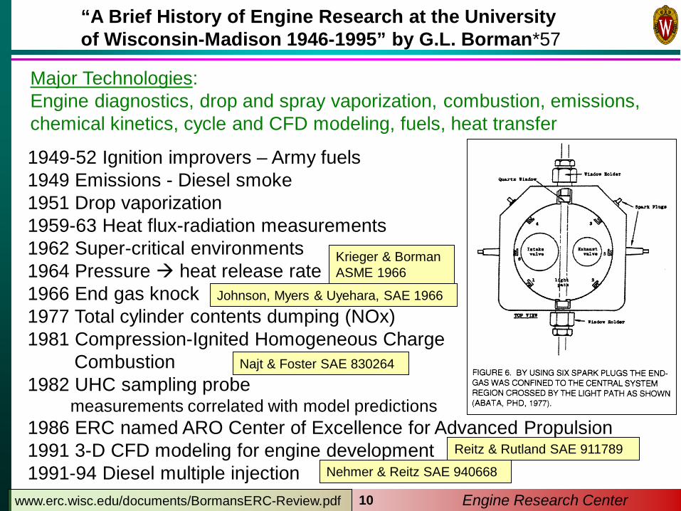
1949-52 Ignition improvers – Army fuels1949 Emissions - Diesel smoke1951 Drop vaporization1959-63 Heat flux-radiation measurements1962 Super-critical environments1964 Pressure heat release rate1966 End gas knock1977 Total cylinder contents dumping (NOx)1981 Compression-Ignited Homogeneous Charge
Combustion 1982 UHC sampling probe
measurements correlated with model predictions1986 ERC named ARO Center of Excellence for Advanced Propulsion1991 3-D CFD modeling for engine development1991-94 Diesel multiple injection
Major Technologies: Engine diagnostics, drop and spray vaporization, combustion, emissions,chemical kinetics, cycle and CFD modeling, fuels, heat transfer
“A Brief History of Engine Research at the University of Wisconsin-Madison 1946-1995” by G.L. Borman*57
Najt & Foster SAE 830264
Krieger & Borman ASME 1966
Nehmer & Reitz SAE 940668
Johnson, Myers & Uyehara, SAE 1966
Reitz & Rutland SAE 911789
www.erc.wisc.edu/documents/BormansERC-Review.pdf

Engine Research Center11
Development of today’s fuels (1910-1970)
“Early” history of ERC research (1946-1995)
ERC research in advanced fueling strategies– Multiple injections (1994)– Gasoline compression ignition (2001)– Dual fuel RCCI (2009)– Dual injector, dual fuel strategies (2014-15)
Conclusions and future research directions
Outline

Engine Research Center12
ERC: Advanced fueling strategies – multiple injectionsNehmer & Reitz SAE 940668Tow, Pierpont & Reitz SAE 940897Pierpont, Montgomery & Reitz
SAE 950217
1994: Nehmer, D.A., MSMeasurement of the Effect of Injection Rate and Split Injections On Diesel Engine Soot and NOx Emissions
1994: Tow, T., MSThe Effect of Multiple Pulse Injection, Injection Rate and Injection Pressure on Particulate and NOx Emissions from a D.I. Diesel Engine
1994: Pierpont, D.A., MSAn Experimental Study of the Effect of Injection Parameters and EGR on D.I. Diesel Emissions and Performance
[S1]
[D1]
[D2]
[D3]
[D4]
l
l
l l l
H
H
HH H
T
T
TT T
:
:
:: :
G
G
G G
0.020.04
0.060.08
0.10.120.140.160.180.2
3 4 5 6 7 8 9
Part
icul
ate
(g/b
hp-h
r)
NOx (g/bhp-hr)
l [S1] Single .6H [D1] 13-(0)-87T [D2] 16-(0)-84: [D3] 21-(0)-79G [D4] 32-(0)-68
Common-rail injector90MPa injection pressure125 degree spray angle1600 rev/min,75% load
Single injections Han et al. SAE 960633
Split injections

Engine Emissions vs Start of Injection Timing700 RPM PHI=0.22
0
20
40
60
80
100
120
-360 -300 -240 -180 -120 -60 0
Injection Angle (deg ATDC)
CO a
nd U
HC E
mis
sion
s (g
/kg-
fuel
)
0
3
6
9
12
15
18
CO
UHC
NOx
Particulate Matter PM a
nd N
Ox
Emis
sion
s (g
/kg-
fuel
)
Engine Research Center13
ERC: Advanced fueling strategies – fuels and split injectionMarriott & Reitz SAE 2002-01-0418Canakci & Reitz IJER 2003Hanson et al. SAE 2009-01-1442Dempsey & Reitz SAE 2011-01-0356Ra et al. SAE 2011-01-1182
2001: Marriott, Craig D. MSAn Experimental Investigation of Direct Injection for Homogeneous and Fuel-Stratified Charge Compression Ignited Combustion Timing Control
Gasoline-fueled HD diesel engine - Low pressure common rail, hollow cone injector- GCI, PFS, PPC, ….
HCCI Stratified
Marriott & Reitz US Patent 6,668,789 – 2003
0
5
10
15
20
25
30
35
40
700 900 1100 1300 1500 1700 1900Engine Speed (rev/min)
NOx
Emis
sion
s (g
/kg-
fuel
)
85
88
91
94
97
Single Injection NOx Split Injection NOxSingle Injection Comb. Eff. Split Injection Comb. Eff.
Com
bust
ion
Effic
ienc
y (%
)
NOx Emission and Combustion Efficiency Comparison: Single vs Split Injections
Intake Air Temp = 119 C PHI = 0.21
SOI 300100o: SOI1 ~180o (60%); SOI2 ~90o
∆P~100bar

Kalghatgi et al. SAE 2007-01-0006
ERC: Advanced fueling strategies - diesel vs. gasoline Ra et al., "Parametric Study of Diesel Engine Operation with Gasoline," Combustion Science and Technology, Vol. 181, No. 2, pp.350-378, 2009
Engine Research Center
Engineheavy-duty, flat cylinder
head, shallow bowl
Bore x Stroke [mm] 127 x 154
Compression ratio 14.0
Injector hole, dia [µm] 8, 200
Engine speed [rpm] 1200
Swirl ratio 2.4
Intake temp [C], Pressure
[bar]
40, 2.0
Oxygen @ IVC/EGR [%] 15.8/25
Pilot split ratio [%] 30
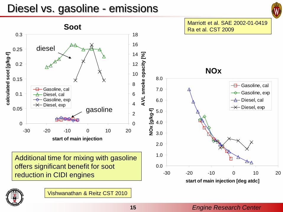
Diesel vs. gasoline - emissions
Additional time for mixing with gasoline offers significant benefit for soot reduction in CIDI engines
0
0.05
0.1
0.15
0.2
0.25
0.3
-30 -20 -10 0 10 20start of main injection
calc
ulat
ed s
oot [
g/kg
-f]
0
2
4
6
8
10
12
14
16
18
AVL
sm
oke
opac
ity [%
]
Gasoline, calDiesel, calGasoline, expDiesel, exp
0.0
1.0
2.0
3.0
4.0
5.0
6.0
7.0
8.0
-30 -20 -10 0 10 20start of main injection [deg atdc]
NO
x [g
/kg-
f]
Gasoline, calGasoline, expDiesel, calDiesel, exp
diesel
gasoline
Soot
NOx
Engine Research Center15
Marriott et al. SAE 2002-01-0419Ra et al. CST 2009
Vishwanathan & Reitz CST 2010

6 bar IMEP, 1300 rpm
0 10 20 30 40 50 600
20
40
60
80
100
250
180 g/kW-hr
MISFIRE
190g/kW-hr
PRF
[-]
EGR Rate [%]
10 bar/deg.
5.6 bar/deg.
Combustion optimization - fuel and EGR selectionHCCI simulations used to choose
optimal EGR rate and PRF (isooctane/n-heptane) blend
Predicted contours agree well with HCCI experiments
Fuel reactivity must change with EGR rate for optimum ISFC
As load is increased the minimum ISFC cannot be achieved with either neat diesel fuel or neat gasoline
170
190
210
230240
Net ISFC [g/kW-hr]
EGR Rate [%]
PRF
Kokjohn et al. SAE 2009-01-2647
Gasoline-diesel“cocktail”
Gas
olin
eD
iese
l
16 Engine Research Center
ERC PRF mechanismRa & Reitz, CNF 2008

17 Engine Research Center
Direct injected dieselPort injected gasoline
Diesel-80 to -50 -45 to -30
Crank Angle (deg. ATDC)
Inje
ctio
n Si
gnal
Squish Conditioning
Ignition Source
Gasoline
Diesel
Gasoline
Optimized Reactivity Controlled Compression Ignition
CFD with Genetic Algorithms used to optimize multiple injection strategy
GA: Senecal & Reitz SAE 2000-01-1890
Kokjohn et al. SAE 2009-01-2647

ERC: Heavy- and light-duty experimental engines
Engine Heavy Duty Light Duty
Engine CAT SCOTE GM 1.9 L
Displ. (L/cyl) 2.44 0.477
Bore (cm) 13.72 8.2
Stroke (cm) 16.51 9.04
Squish (cm) 0.157 0.133
CR 16.1:1 15.2:1
Swirl ratio 0.7 2.2
IVC (°ATDC) -85 and -143 -132
EVO(°ATDC) 130 112
Injector type Common rail
Nozzle holes 6 8
Hole size (µm) 250 128
LDHD
Engine size scalingStaples, SAE 2009-01-1124
18 Engine Research Center

IMEP (bar) 9
Speed (rpm) 1300
EGR (%) 43
Equivalence ratio (-) 0.5
Intake Temp. (°C) 32
Intake pressure (bar) 1.74
Gasoline (% mass) 76 82 89
Diesel inject press. (bar) 800
SOI1 (°ATDC) -58
SOI2 (°ATDC) -37
Fract. diesel in 1st pulse 0.62
IVC (ºBTDC)/Comp ratio 143/16
Computer modeling predictions confirmedCombustion timing and Pressure Rise Rate control with diesel/gasoline ratio
Effect of gasoline percentage
Hanson et al. SAE 2010-01-0864
-30 -20 -10 0 10 20 300
2
4
6
8
10
12
14 Experiment Simulation
Crank [°ATDC]
Pres
sure
[MPa
]
0
200
400
600
800
1000
1200
1400
89%Gasoline
76%
82%
89%
App
aren
t Hea
t Rel
ease
Rat
e [J
/°]
NeatGasoline
NeatDiesel Fuel
Dual-fuel can be used to extend load limits of either pure diesel or gasoline
Experimental validation - HD Caterpillar SCOTE
19 Engine Research Center

4 6 8 10 12 14 164548515457
0.000.010.020.030.00.10.20.3
Heavy-duty RCCI (gas/gas+3.5% 2-EHN, 1300 RPM)Heavy-duty RCCI (E-85/Diesel, 1300 RPM)Heavy-duty RCCI (gas/diesel 1300 RPM)
Gro
ssIn
d.Ef
ficie
ncy
Gross IMEP [bar]
Soot
[g/k
W-h
r]
HD Target (~2010 Levels)
NO
x[g
/kW
-hr]
HD Target (~2010 Levels)
RCCI – high efficiency, low emissions, fuel flexibility
Splitter, SAE 2010-01-2167; Hanson, SAE 2011-01-0361, Kokjohn IJER 2011
Indicated efficiency of 58±1%achieved with E85/diesel
Emissions met in-cylinder, without need for after-treatment
Considerable fuel flexibility,including ‘single’ fuel operation
Diesel can be replaced with <0.5% total cetane improver (2-EHN/DTBP) in gasoline- less additive than SCR DEF
20 Engine Research Center
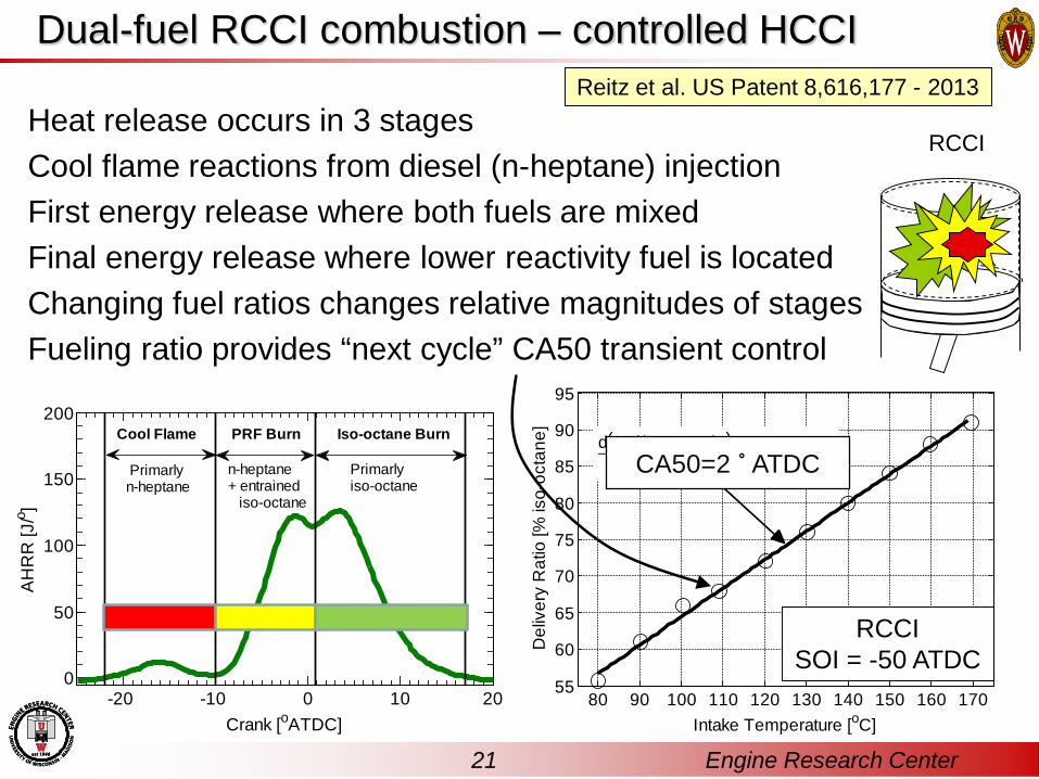
Dual-fuel RCCI combustion – controlled HCCI
Heat release occurs in 3 stages Cool flame reactions from diesel (n-heptane) injectionFirst energy release where both fuels are mixedFinal energy release where lower reactivity fuel is locatedChanging fuel ratios changes relative magnitudes of stagesFueling ratio provides “next cycle” CA50 transient control
21-20 -10 0 10 20
0
50
100
150
200
Crank [oATDC]
AH
RR
[J/o ]
Primarly iso-octane
n-heptane+ entrained iso-octane
Iso-octane BurnPRF BurnCool Flame
Primarly n-heptane
80 90 100 110 120 130 140 150 160 17055
60
65
70
75
80
85
90
95
Intake Temperature [oC]
Del
iver
y R
atio
[% is
o-oc
tane
]
d(Del i ver yRati o)d(I nt:Temp:)
= 0:4per cent
KCA50=2 ˚ ATDC
RCCISOI = -50 ATDC
RCCI
Reitz et al. US Patent 8,616,177 - 2013
21 Engine Research Center

22 Engine Research Center
GM 1.9L Engine Specifications
Multi-cylinder RCCI - transient operation
Engine Type EURO IV DieselBore 82 mm Stroke 90.4 mm Displacement 1.9 liters Cylinder Configuration
Inline 4 4 valves per cylinder
Swirl Ratio Variable (2.2-5.6)Compression Ratio 17.5
EGR System Hybrid High/Low Pressure, Cooled
ECU (OEM) Bosch EDC16 ECU (new) Drivven
Common Rail Injectors
Bosch CRIP2-MI 148° Included Angle7 holes,440 flow number.
Port Fuel Injectors
Delphi2.27 g/s steady flow400 kPa fuel pressure
UW RCCI Hybrid Vehicle
SAE Paper 2015-01-0837
Highway Fuel Economy Testing of an RCCI Series Hybrid VehicleReed Hanson, Shawn Spannbauer, Christopher Gross, Rolf D. Reitz, University of Wisconsin; Scott Curran, John Storey, Shean Huff, ORNL

Engine Research Center23
RCCI operating range – ORNL & ERC
Load expansion via alternativefuels, VVA, dual direct injection, …..
. UDDS/FTP cycle
RCCI offers diesel-like or better BTE across speed-load range
ORNL simulations indicate RCCI offers >20% fuel economy c.f. 2009 PFI engines
Wagner, Aramco Workshop, 2014

ERC: Advanced fueling strategies – RCCI load expansion
Direct injection of both diesel and gasoline Stock piston geometry has 2 zones:
- Squish with high surface/volume ratio, - bowl with low S:V ratio
Engine Research Center24
Lim and Reitz ASME GTP, 136, 2014Lim and Reitz SAE 2014-01-1320
High load/speed simulations ERC KIVA3V-R2, GA optimizationDiscrete Multi-Component fuel evaporationERC PRF mechanism
- 46 species, 142 reactionsGasjet model for reduced grid dependencyBoth injectors at cylinder axis
HD RCCI engine: 21 bar IMEP gasoline/dieselIVC conditions: 3.42 bar, 90°C, 46%EGR
2015: Lim, J., PhDHigh Power Output Operation of RCCI Combustion

ERC: Advanced fueling strategies – DDFS strategy
Engine Research Center25
Caterpillar 3401 SCOTECR=14.9
2015: Wissink, M.L., PhDDirect Injection for Dual Fuel Stratification (DDFS):Improving the Control of Heat Release in Advanced IC Engine Combustion Strategies
Wissink & Reitz SAE 2015-01-0856
RCCI
PPC
PPC
DDFS

ERC: Advanced fueling strategies – DDFS emissions
Engine Research Center26
0
More final late-injected fuel
EPA 2010

ERC: Advanced fueling strategies – DDFS efficiency
Engine Research Center27
~14% reduction ~12% reduction
~1% increase
~30% increase
~13% reduction
DDFS provides high efficiency, lower noise/COV, lower heat loss/increased exhaust loss – reducing turbo requirements
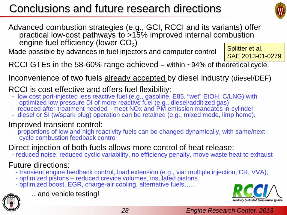
Conclusions and future research directionsAdvanced combustion strategies (e.g., GCI, RCCI and its variants) offer
practical low-cost pathways to >15% improved internal combustion engine fuel efficiency (lower CO2)
Made possible by advances in fuel injectors and computer control
RCCI GTEs in the 58-60% range achieved − within ~94% of theoretical cycle.
Inconvenience of two fuels already accepted by diesel industry (diesel/DEF)RCCI is cost effective and offers fuel flexibility:
- low cost port-injected less reactive fuel (e.g., gasoline, E85, “wet” EtOH, C/LNG) with optimized low pressure DI of more-reactive fuel (e.g., diesel/additized gas)
- reduced after-treatment needed - meet NOx and PM emission mandates in-cylinder- diesel or SI (w/spark plug) operation can be retained (e.g., mixed mode, limp home).
Improved transient control:- proportions of low and high reactivity fuels can be changed dynamically, with same/next-
cycle combustion feedback controlDirect injection of both fuels allows more control of heat release:
- reduced noise, reduced cyclic variability, no efficiency penalty, move waste heat to exhaust
Future directions:- transient engine feedback control, load extension (e.g., via: multiple injection, CR, VVA),- optimized pistons – reduced crevice volumes, insulated pistons.- optimized boost, EGR, charge-air cooling, alternative fuels……
.. and vehicle testing!
28 Engine Research Center, 2013
Splitter et al. SAE 2013-01-0279

2025 and beyond….Voyage to new concepts in engine combustion
California ARB:90% reduction in NOx emissions by 2031 (0.02 g/bhp·hr)80% reduction in GHG emissions (below 1990 levels) by 2050 Governor’s 50% petroleum reduction target by 2030 (renewable fuels), and continued reductions in air toxics & diesel PM (PN 6×10¹¹ 1/km).

Backup
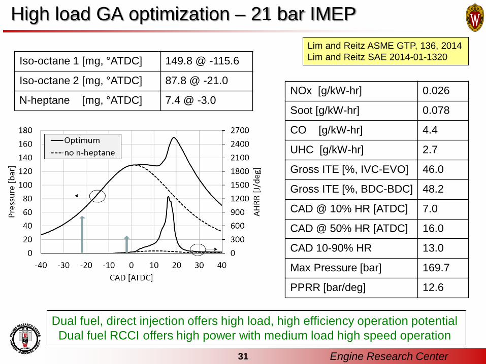
High load GA optimization – 21 bar IMEP
NOx [g/kW-hr] 0.026
Soot [g/kW-hr] 0.078
CO [g/kW-hr] 4.4
UHC [g/kW-hr] 2.7
Gross ITE [%, IVC-EVO] 46.0
Gross ITE [%, BDC-BDC] 48.2
CAD @ 10% HR [ATDC] 7.0
CAD @ 50% HR [ATDC] 16.0
CAD 10-90% HR 13.0
Max Pressure [bar] 169.7
PPRR [bar/deg] 12.6
Iso-octane 1 [mg, °ATDC] 149.8 @ -115.6
Iso-octane 2 [mg, °ATDC] 87.8 @ -21.0
N-heptane [mg, °ATDC] 7.4 @ -3.0
Engine Research Center31
Dual fuel, direct injection offers high load, high efficiency operation potentialDual fuel RCCI offers high power with medium load high speed operation
Lim and Reitz ASME GTP, 136, 2014Lim and Reitz SAE 2014-01-1320

32 Engine Research Center
Limits of dual fuel RCCI efficiency
Exp. GT POWER
GT POWER
Compression ratio 14.88 14.88 18.6
IMEPn (bar) 8.00 7.86 8.69
Fueling (mg/cyc) 87.13 87.13 87.13
Gross Therm Eff. (%) 54.3 54.5 59.7
Net Therm Eff. (%) 52.0 52.1 57.5
BTE (%) 45.3 45.1 49.1
FMEP (bar) 1.03 1.0 1.2Convection HX N/A 0.4 0.2Comb. Eff. (%) 98 98 99Intake Pressure (bar) 1.5 1.5 1.68Exhaust Pressure (bar) 1.625 1.625 1.75Turbo eff. (air filter + DOC)
67.5 62.3 72.8
Calibrate 0-D code with experimental dataUse to determine:
- initial conditions - geometry
Results:60% GTE possible with:High Cr Lean operation (Φ<0.3)50% reduction in heat transfer &combustion losses
• Deactivate under-piston oil jet cooling
Splitter et al. SAE 2013-01-0279

High efficiency demonstrated
Simulation heat transfer tuned to match data
- 14.88:1 Piston required HX = 0.4
- 18.7:1 required HX = 0.3Pancake design ~1.2 less
surface area18.7:1 without oil cooling
required HX = 0.2
GTE (%) IMEPg (bar) NTE (%) IMEPn
(bar) EXP (pt. 83) 59.1 6.82 55.0 6.27 GT Power HX =0.2 58.8 6.79 54.8 6.25 GT Power HX =0.4 56.7 6.55 52.8 6.02
GTE(%)
IMEPg(bar)
NTE(%)
IMEPn(bar)
Experiment 59.1 6.82 55.0 6.27Model, HX =0100% comb. η 62.4 7.12 58.5 6.85
Model, HX =0100% comb.η,0% EGR
63.4 7.23 61.0 6.95
94% of maximum theoretical cycle efficiency achieved !
-40 -30 -20 -10 0 10 20 30 40-15
0153045607590
105120135150
E85 / 3% EHN+91 PON RCCI43°C intake, 42% EGR, 6.3 bar IMEPn
EXP, Squirter off, 43% EGR, Oil Matrix Point 83 GTPower, HX=0, 100% comb. η, 43% EGR GTPower, HX=0, 100% comb. η, 0% EGR
Pres
sure
(bar
)
Crank Angle (°CA ATDC)
0
150
300
450
600
750
AHR
R (J
/° CA
)
Splitter et al. “RCCI Engine Operation Towards 60% Thermal Efficiency”, SAE 2013-01-0279
33 Engine Research Center
Ultra high efficiency, dual fuel RCCI combustion
DI: 3%EHN+91ONPFI: E85TIVC = 43 CEGR = 42%
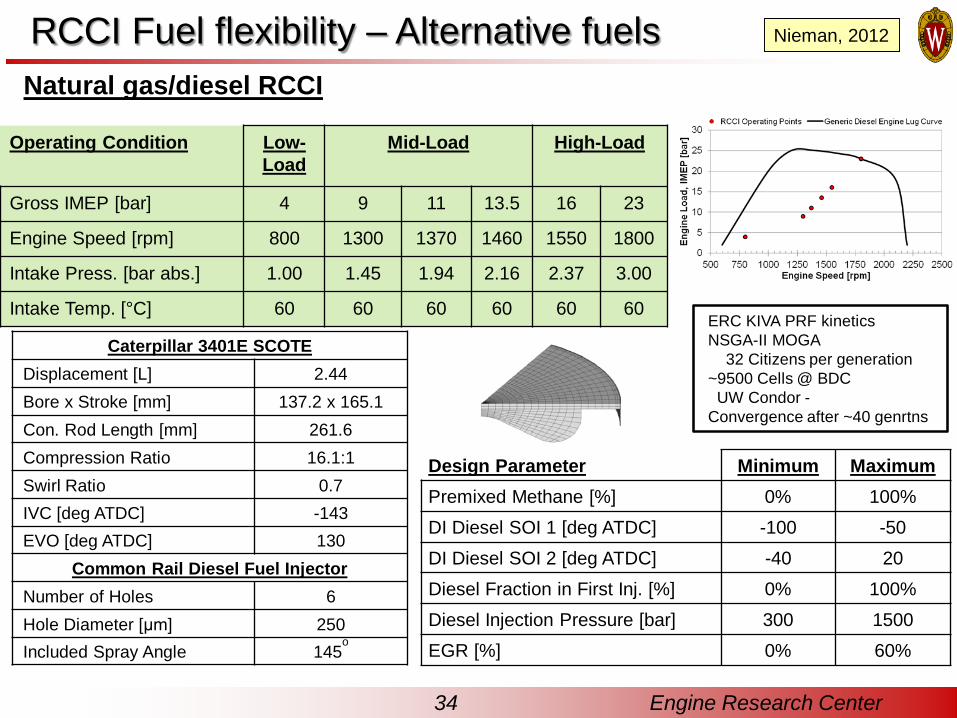
Operating Condition Low-Load
Mid-Load High-Load
Gross IMEP [bar] 4 9 11 13.5 16 23
Engine Speed [rpm] 800 1300 1370 1460 1550 1800
Intake Press. [bar abs.] 1.00 1.45 1.94 2.16 2.37 3.00
Intake Temp. [°C] 60 60 60 60 60 60
Caterpillar 3401E SCOTEDisplacement [L] 2.44Bore x Stroke [mm] 137.2 x 165.1Con. Rod Length [mm] 261.6Compression Ratio 16.1:1Swirl Ratio 0.7IVC [deg ATDC] -143EVO [deg ATDC] 130
Common Rail Diesel Fuel InjectorNumber of Holes 6Hole Diameter [μm] 250Included Spray Angle 145
o
Design Parameter Minimum MaximumPremixed Methane [%] 0% 100%DI Diesel SOI 1 [deg ATDC] -100 -50DI Diesel SOI 2 [deg ATDC] -40 20Diesel Fraction in First Inj. [%] 0% 100%Diesel Injection Pressure [bar] 300 1500EGR [%] 0% 60%
Natural gas/diesel RCCI
ERC KIVA PRF kineticsNSGA-II MOGA
32 Citizens per generation~9500 Cells @ BDC
UW Condor -Convergence after ~40 genrtns
34 Engine Research Center
Nieman, 2012RCCI Fuel flexibility – Alternative fuels

Double vs. triple injection
Results 2 Inj. Optimum 3 Inj. OptimumSoot [g/kW-hr] 0.004 0.004NOx [g/kW-hr] 0.24 0.10CO [g/kW-hr] 10.8 7.3UHC [g/kW-hr] 10.5 3.8ηgross [%] 45.1% 47.1%
4 bar IMEP 23 bar IMEP
Results 2 Inj. Optimum 3 Inj. OptimumSoot [g/kW-hr] 0.079 0.014NOx [g/kW-hr] 0.08 0.17CO [g/kW-hr] 6.0 1.7UHC [g/kW-hr] 9.4 3.3ηgross [%] 44.1% 46.5%
44.1% 42.4%
7.9% 5.6%
46.5%43.0%
8.5% 2.0%0%5%
10%15%20%25%30%35%40%45%50%
Gross Work Exhaust Loss Heat Transfer Combustion Loss
% o
f Fue
l Ene
rgy
In2 Inj. Optimum3 Inj. Optimum45.1%
31.5%
17.1%
6.3%
47.1%
31.9%
18.7%
2.4%0%5%
10%15%20%25%30%35%40%45%50%
Gross Work Exhaust Loss Heat Transfer Combustion Loss
% o
f Fue
l Ene
rgy
In
2 Inj. Optimum3 Inj. Optimum
35 Engine Research Center
Nieman MS 2012RCCI Fuel flexibility – Alternative fuels

0° ATDC2° ATDC4° ATDC6° ATDC8° ATDC10° ATDC12° ATDC14° ATDC16° ATDC
• Achieve low soot, despite late 3rd injectiono Combustion starts in squish region, so diesel #3 injects
into a relatively cool environmento Fairly small amount injected
18° ATDC
(Isosurface = 1600K)Isosurface
23 bar IMEP, triple Injection
36 Engine Research Center
Nieman MS 2012RCCI Fuel flexibility – Alternative fuels