eracle wearable emg gesture recognition system · ltraggio e al riconoscimento del movimento sono...
TRANSCRIPT
POLITECNICO DI MILANOMaster’s Degree in Computer Science Engineering
Department of Electronics and Computer Science Engineering
ERACLE
Wearable EMG Gesture Recognition
System
AI & R Lab
Artificial Intelligence and Robotics
Laboratory of Politecnico di Milano
Supervisor: Prof. Giuseppina Gini
Assistant supervisor: Ing. Paolo Belluco
Master’s thesis of:
Luigi Seregni, registration number 734799
Academic Year 2009-2010


To Andrea,
Maria Rosa
and Valentina

Abstract
Eracle is a hand gesture recognition system mainly designed for Hu-
man Computer Interaction. It could be employed in Virtual Reality
simulations, video games, Augmented Reality environments and Home
Automation applications.
It is focused on two different features: EMG signals processing and
wearable computer. EMG are biometric signals produced by the mus-
cle during a contraction that are mainly employed in biomedical field
for prosthesis control. The whole system has been developed using mo-
bile devices to realize a completely wearable system. In particular, the
whole sampling process has been carried out by an acquisition glove
worn by the user, while the computing core is fully implemented on
Nvidia Tegra 2.
The core of this thesis is the development of the software computing
core of Eracle system, while the acquisition glove and the EMG Board
(that provides analog to digital conversion of the sampled signal) have
been realized in previous works.
The aim of the project is to develop a wearable recognition system
based on EMG signals that is able to recognize at least four differ-
ent hand gestures. The performed tests have shown that Eracle can
correctly identify up to five movements with a performance of about
90%. The achieved results are very interesting for such kind of HCI
application, that could be effectively employed in daily life computer
interaction, making it easier and more immersive.
I

Sommario
Questa tesi documenta la realizzazione di un sistema per il riconosci-
mento dei movimenti della mano. Il nome del progetto e “Eracle”,
poiche il riconoscimento avviene grazie all’analisi dei segnali elettro-
miografici (EMG) emessi dai muscoli dell’avambraccio dell’utente. Lo
scopo consiste nel realizzare un sistema indossabile che possa essere
facilmente utilizzato per interagire con un’apparecchiatura informatica.
Le applicazioni di questo dispositivo sono molteplici e spaziano dalle
simulazioni di Realta Virtuale, ai videogiochi, alla Realta Aumentata
fino a domotica.
Il progetto Eracle e focalizzato su due aspetti principali: i segnali elet-
tromiografici e i dispositivi indossabili. I segnali EMG sono largamente
utilizzati in campo biomedico per il controllo delle protesi, soprattutto
per quanto riguarda i pazienti amputati a livello della mano. Inoltre,
l’analisi di questo tipo di segnali e utile per la diagnosi di lesioni ai
muscoli o ai nervi.
Il secondo punto focale della tesi e costituito dai dispositivi indossabili,
ovvero le apparecchiature caratterizzate da dimensioni tanto ridotte
da poter essere agevolmente indossate da un utente nelle attivita della
vita quotidiana. L’uso di questo tipo di dispositivi semplifica alcune
attivita tipicamente compiute dall’uomo (nel nostro caso, l’interazione
con un computer) oppure estende le capacita sensoriali dell’utente.
Eracle e composto fondamentalmente da due unita: il guanto di ac-
quisizione e il modulo di elaborazione del segnale. Il primo e stato
sviluppato dall’ Ing. Paolo Belluco in precedenti progetti e consiste in
un guanto di materiale elastico indossato dall’utente sull’avambraccio.
All’intero del guanto sono presenti gli elettrodi che rilevano il segnale
elettromiografico emesso dai muscoli e la scheda di acquisizione (EMG
III
Board) che fornisce la conversione analogico-digitale degli EMG. I se-
gnali di input vengono campionati da tre diversi canali in modalita
differenziale.
L’unita di calcolo e stata implementata sulla piattaforma Nvidia Tegra
2. I vari moduli software che provvedono all’elaborazione del segnale, al
filtraggio e al riconoscimento del movimento sono stati completamente
sviluppati all’interno di questo progetto. Alcune strutture matematiche
(matrici, vettori), l’algoritmo di filtraggio FastICA e la Rete Neurale
utilizzata dal sistema di riconoscimento sono state fornite dalla libre-
ria open-source LTIlib. L’intero codice sorgente e stato ricompilato ed
adattato per l’architettura ARM Cortex-A9 del processore Tegra.
I risultati sperimentali mostrano che Eracle e in grado di distinguere
fra cinque movimenti differenti con una percentuale di successo media
del 90%. I cinque movimenti utilizzati per la fase di test sono:
• chiusura della mano;
• estensione del polso;
• flessione del polso;
• apertura della mano;
• “click”: questo gesto simula il click di selezione di un mouse;
viene eseguito appoggiando il polpastrello dell’indice su quello
del pollice ed esercitando una leggera pressione.
Durante lo sviluppo del progetto ci siamo focalizzati principalmente
sulla precisione di Eracle nell’identificare correttamente il gesto com-
piuto e sulle proprieta di ripetibilita del sistema.
Quest’ultimo aspetto e essenziale, poiche solitamente la fase di adde-
stramento e di utilizzo del riconoscitore avvegono in tempi differenti,
durante i quali l’utente toglie il guanto di acquisizione.
Tutti i moduli software sviluppati sulla piattaforma Tegra sono stati
realizzati appositamente per essere il piu possibile indipendenti gli uni
dagli altri. Questa scelta e ottima per quanto riguarda la fase di debug
- poiche e possibile monitorare i risultati ottenuti da ogni modulo -
tuttavia porta ad un aumento del tempo di riconoscimento del gesto
principalmente dovuto al numero di operazioni di I/O su file.
Per questi motivi, il principale sviluppo futuro di questo progetto con-
sistera nel ridurre il tempo necessario al riconoscimento diminuendo il
numero dei campioni analizzati in fase di elaborazione e introducendo
alcune ottimizzazioni legate alla scrittura e lettura dei file. Crediamo
che, grazie a tali modifiche, sara possibile migliorare drasticamente il
tempo di riconoscimento; inoltre, qualora le prestazioni raggiungessero
un livello real-time, sara possibile applicare Eracle in un contesto in-
dustriale per il controllo di manipolatori robotici.
Stato dell’arte dei dispositivi mobili per riconoscimento del
gesto
Come specificato in precedenza, questa tesi e focalizzata su due temi: i
segnali elettromiografici utilizzati per il riconoscimento del movimento
e i dispositivi indossabili. Prima di delineare le tecniche utilizzate nello
sviluppo di questo progetto e l’effettiva realizzazione del sistema Eracle
e necessario descrivere l’attuale stato dell’arte di entrambi gli aspetti
chiave della tesi.
Il riconoscimento del movimento puo essere effettuato con molteplici
tecniche:
• Sistemi inerziali come accelerometri o giroscopi, che forniscono
posizione e orientamento dell’oggetto controllato.
• Segnali biometrici ovvero tutti quelli generati dal corpo umano.
Questa classe include i segnali EMG utilizzati nel progetto, ma
anche gli EEG e gli EOG. La scelta degli EMG non e casuale, ma
e motivata prima di tutto dai numerosi esempi di applicazione
di questa tecnlogia al riconoscimento del movimento e dalla loro
facilita di acquisizione rispetto a tecniche quali l’ elettroencefalo-
grafia.
• Sistemi basati su analisi dell’immagine: questa classe com-
prende tutti i sistemi che utilizzano metodi di estrazione di pri-
mitive da immagini per identificare il movimento dell’utente. Me-
diante questa classe di dispositivi e possibile identificare un gran
numero di gesti (solitamente almeno dieci), tuttavia essi richie-
dono apparecchiature costose e di dimensioni tali da non poter
essere considerate indossabili.
I dispositivi indossabili appartengono fondamentalmente a due cate-
gorie: i PIC o le piattaforme SoC realizzate per Netbook e Smartphone
(fra cui il processore Tegra). I primi sono caratterizzati da un basso
costo e da una considerevole difficolta di programmazione, mentre i

secondi sono programmabili solitamente con linguaggi di alto livello
(C++ nel caso del Tegra), ma hanno un costo piuttosto elevato. Inol-
tre, molti SoC (come il processore Tegra da noi utilizzato) non sono
disponibili sul mercato commerciale italiano, ma sono destinati solo ad
alcuni partner per sviluppi sperimentali.
E’ possibile distinguere i dispositivi indossabili anche in base al loro
Sistema Operativo, i due maggiormente utilizzati sono la piattaforma
open-source Android e quella di Microsoft Windows CE (utilizzata
nel progetto Eracle). Recentemente, Microsoft ha rilasciato l’innovativo
sistema Windows Phone 7 che dovrebbe semplificare la fase di svi-
luppo e l’eventuale porting del codice sui dispositivi mobili.
Piano generale e descrizione del progetto
Lo scopo del progetto e realizzare un riconoscitore del movimento
basato sull’elaborazione del segnale elettromiografico. Nonostante l’
utilizzo degli EMG il principale campo di applicazione di Eracle non
e quello del controllo delle protesi, ma quello della Human Computer
Interaction. Eracle potrebbe essere impiegato in simulazioni inerenti
la Realta Virtuale o aumentata, nonche in campi innovativi quali la
domotica. Le differenze fra Eracle e le precedenti implementazioni di
riconoscitori basati su EMG sono principalmente due:
• l’utente finale, contrariamente ad altri progetti realizzati elabo-
rando il segnale elettromiografico per pilotare una protesi, Eracle
puo essere utilizzato da qualunque persona senza che sia neces-
sario un’intensa e specifica fase di addestramento;
• l’hardware utilizzato, che e completamente indossabile, grazie
al peso ridotto e alle dimensioni minime.
Independent Component Analysis
Questo algoritmo viene utilizzato fondamentalmente per ridurre il ru-
more sui segnali acquisiti e per eliminare il crosstalking. Quest’ultimo
e un fenomeno tipico legato ai segnali elettromiografici che si verifica
perche ogni movimento compiuto dalla mano e il risultato della con-
trazione simultanea di piu muscoli; per cui il segnale rilevato dagli
elettrodi e una combinazione dei segnali originariamente generati. In
campo medico questo problema viene superato utilizzando degli elet-
trodi ad ago, che tuttavia non possono essere impiegati in un’ applica-
zione di HCI.

Poiche ICA fa parte della classe di algoritmi detta Blind Source Sepa-
ration (BSS) e in grado di separare e isolare i segnali originali. ICA e
stato applicato all’analisi dei segnali biometrici solo in tempi recenti.
Dispositivi hardware
I dispositivi utilizzati per la realizzazione del progetto Eracle sono fon-
damentalmente due: la scheda EMG (EMG Board) e il Devkit Nvidia
Tegra 2.
Il primo si occupa della conversione analogico-digitale del segnale EMG
acquisito mediante tre canali differenziali. Il processo di conversione e
affidato ad un PIC16F688 Microchip.
Nvidia Tegra 2 e un System on Chip appositamente realizzato per piat-
taforme mobili quali Netbook e Smarthphone. Il sistema viene gestito
da Windows CE Embedded 6, che fornisce alcune potenzialita di un
Sistema Operativo di un PC su una piattaforma di dimensioni ridotte.
Il dispositivo e stato interamente programmato in C++ utilizzando
direttamente Visual Studio 2008 e le apposite SDK rilasciate da Mi-
crosoft.
I due elementi hardware sono connessi via USB grazie ai driver FTDI.
Sviluppo del progetto
Questa tesi e principalmente orientata alla realizzazione dei moduli
software per l’elaborazione del segnale elettromiografico campionato
mediante il guanto di acquisizione.
Tutti i moduli sono stati implementati “from scratch” sulla piattaforma
Tegra e consistono fondamentalmente in:
• serial port manager: che gestisce la comunicazione dei dati fra
l’EMG board e il Tegra;
• parser: i dati di input vengono divisi su tre file diversi, ognuno
contenente un numero prefissato di campioni;
• FastICA: che provvede al filtraggio dei segnali, alla separazione
delle sorgenti e all’eliminazione (almeno parziale) del crosstalking;
• RMS: questo modulo calcola il Root Mean Square di ogni canale
per ogni gesto acquisito;
• NN Trainer: questa unita addestra la Rete Neurale con i valori
di RMS calcolati nella sezione precedente;
• NN Recognizer: l’ultimo modulo del progetto permette il ri-
conoscimento del movimento eseguito dall’utente mediante l’ uti-
lizzo della Rete Neurale precedentemente addestrata.
Alcune strutture matematiche (matrici, vettori), l’algoritmo di filtrag-
gio FastICA e la Rete Neurale utilizzata nel progetto sono state fornite
dalla libreria open-source LTIlib che e stata adattata all’architettura
del processore ARM Cortex-A9 presente sul Devkit Tegra.
Test
I test eseguiti hanno come scopo principale quello di identificare e
migliorare l’accuratezza del sistema in fase di riconoscimento.
Eracle ha dato prova di riconoscere correttamente fino a cinque gesti
differenti con una performance media del 90%.
Inoltre, alcuni esperimenti sono stati compiuti con successo su un altro
soggetto estraneo al progetto, al fine di testare la robustezza di Eracle
e l’effettiva facilita di utilizzo.
Conclusioni e sviluppi futuri
Eracle puo essere utilizzato per migliorare l’interazione nei videogiochi,
nelle simulazioni di Realta Virtuale o Aumentata, nonche nel campo
della domotica.
E possibile, tuttavia, introdurre numerosi miglioramenti al sistema. Fra
questi il principale riguarda la velocita di computazione che puo essere
- a nostro parere - ridotta a circa la meta del valore attuale mediante
opportuni accorgimenti ed ottimizzazioni legati al numero di campioni
acquisiti e all’entita delle operazioni di I/O eseguite dai moduli di ela-
borazione.
Inoltre, viste le buone performance del sistema, crediamo sia possibile
estendere il numero di movimenti riconosciuti.
Sarebbe interessante introdurre, accanto a FastICA, alcuni algoritmi
di estrazione di features ampiamente utilizzati nell’analisi del segnale,
come ad esempio le Wavelet, per migliorare ulteriormente le prestazioni
in fase di riconoscimento.
Infine, il sistema Eracle potrebbe essere collegato ad altre periferiche
(anche mediante dispositivi wireless) quali ad esempio caschi o disposi-
tivi aptici, per rendere sempre piu immersiva e coinvolgente l’interazione
con l’ambiente virtuale.


Acknowledgements
I sincerely thank my advisor Prof.ssa Giuseppina Gini and my assistant
supervisor Ing.Paolo Belluco for their advices and for all the help and
support they have given me during this project.
Many thanks to Seco s.r.l. that provides us with the DevKit Tegra,
which has been widely employed in developing this thesis.
Thanks to Ing. Dario Cattaneo for his suggestions about the biomedi-
cal features of this project. I would also thank Prof. Umberto Cugini
and Prof.ssa Monica Bordegoni for allowing me to use the laboratories
in Origoni Building of Politecnico di Milano.
I would like to express my sincere gratitude to all the personnel of
KAEMaRT group and particularly to the people of the office at the
first floor (the second near the board-room) of the Department of Me-
chanics of Politecnico di Milano, who have supported me with their
suggestions.
A very special thanks to my parents and to Valentina, who are al-
ways by my side. The fulfillment of this project is largely due to their
advices, their guidance and their continued support which has never
failed.
Ringrazio sinceramente la mia relatrice, Prof.ssa Giuseppina Gini e il
mio correlatore Ing. Paolo Belluco per i loro consigli e per tutto l’aiuto
e il supporto che mi hanno fornito durante la realizzazione di questo
progetto. Un sentito ringraziamento a Seco s.r.l. per aver fornito il
Devkit Tegra, ampiamente utilizzato in questa tesi.
Un grazie all’Ing. Dario Cattaneo per i suggerimenti relativi agli aspetti
biomedici di questo progetto.
Desidero inoltre ringraziare il Prof. Umberto Cugini e la Prof.ssa
Monica Bordegoni per avermi permesso di utilizzare il laboratorio e
le postazioni tecniche presso il padiglione Origoni del Politecnico di
XI
Milano. Vorrei esprimere la mia sincera gratitutine a tutto il perso-
nale del laboratorio KAEMaRT e in particolare ai ragazzi del secondo
ufficio adiacente alla sala Consiglio del Dipartimento di Meccanica del
Politecnico di Milano, che mi hanno supportato con i loro suggerimenti.
Un ringraziamento specialissimo ai miei genitori e a Valentina, che sono
sempre al mio fianco. La realizzazione di questo progetto e dovuta in
gran parte ai loro consigli, alla loro guida e al loro continuo supporto
che non e mai venuto meno.


Contents
Abstract I
Sommario III
Acknowledgements XI
1 Introduction 1
2 Mobile devices for gesture recognition: the state of the
art 5
2.1 Gesture recognition . . . . . . . . . . . . . . . . . . . . 5
2.1.1 Inertial navigation methods for gesture and move-
ment recognition . . . . . . . . . . . . . . . . . 6
2.1.2 Biometrics signals for gesture recognition . . . . 10
2.1.3 Image analysis for gesture recognition . . . . . . 18
2.1.4 Hybrid movement recognition system . . . . . . 19
2.2 Mobile devices . . . . . . . . . . . . . . . . . . . . . . . 22
2.2.1 CPUs and hardware . . . . . . . . . . . . . . . 22
2.2.2 Operative system . . . . . . . . . . . . . . . . . 27
3 Project plan and description 33
3.1 Project goals . . . . . . . . . . . . . . . . . . . . . . . 33
3.1.1 Recognized gestures . . . . . . . . . . . . . . . . 36
3.1.2 Differences from previous implementations . . . 38
3.2 Technological choices: EMG and mobile devices . . . . 40
3.2.1 EMG . . . . . . . . . . . . . . . . . . . . . . . . 40
3.2.2 Nvidia Tegra: a mobile processor . . . . . . . . 41
3.3 General architecture of Eracle project . . . . . . . . . . 45
XV
4 Independent Component Analysis 49
4.1 Principles of ICA . . . . . . . . . . . . . . . . . . . . . 49
4.2 Fields of application of ICA . . . . . . . . . . . . . . . 51
4.3 Estimating data model using ICA . . . . . . . . . . . . 53
4.3.1 Contrast functions . . . . . . . . . . . . . . . . 53
4.3.2 Algorithms for ICA . . . . . . . . . . . . . . . . 56
4.4 ICA for biometric analysis . . . . . . . . . . . . . . . . 59
5 Hardware devices 63
5.1 Nvidia Tegra 2 . . . . . . . . . . . . . . . . . . . . . . 63
5.1.1 Tegra CPU architecture . . . . . . . . . . . . . 64
5.1.2 Developing software on Tegra . . . . . . . . . . 67
5.2 Electromyography board . . . . . . . . . . . . . . . . . 71
5.3 FTDI interface . . . . . . . . . . . . . . . . . . . . . . 73
6 Project development 77
6.1 LTIlib . . . . . . . . . . . . . . . . . . . . . . . . . . . 79
6.1.1 Architecture of LTIlib . . . . . . . . . . . . . . 79
6.1.2 Recompiling LTIlib . . . . . . . . . . . . . . . . 81
6.2 Acquisition glove . . . . . . . . . . . . . . . . . . . . . 84
6.3 Tegra modules . . . . . . . . . . . . . . . . . . . . . . . 88
6.3.1 Serial port manager . . . . . . . . . . . . . . . . 88
6.3.2 Data parsing . . . . . . . . . . . . . . . . . . . 89
6.3.3 Fast ICA module . . . . . . . . . . . . . . . . . 94
6.3.4 Root Mean Square . . . . . . . . . . . . . . . . 98
6.3.5 NN trainer . . . . . . . . . . . . . . . . . . . . . 100
6.3.6 NN classifier . . . . . . . . . . . . . . . . . . . . 104
7 Steps in testing and final results 107
7.1 Test procedure . . . . . . . . . . . . . . . . . . . . . . 107
7.2 Results . . . . . . . . . . . . . . . . . . . . . . . . . . . 110
7.2.1 First set of tests: two gestures . . . . . . . . . . 110
7.2.2 Improving the classifier . . . . . . . . . . . . . . 111
7.2.3 From two to four gestures . . . . . . . . . . . . 113
7.2.4 Tests with different subject . . . . . . . . . . . 117
7.2.5 Last set of tests: five gestures . . . . . . . . . . 119
8 Conclusions and future developments 121
8.1 Future developments . . . . . . . . . . . . . . . . . . . 123
XVI
Bibliography 125
A Code listing 131
A.1 Eracle Serial Port Manager . . . . . . . . . . . . . . . . 131
A.2 Eracle Parser . . . . . . . . . . . . . . . . . . . . . . . 135
A.3 Eracle FastICA . . . . . . . . . . . . . . . . . . . . . . 142
A.4 Eracle RMS . . . . . . . . . . . . . . . . . . . . . . . . 152
A.5 Eracle Neural Network Train . . . . . . . . . . . . . . . 157
A.6 Eracle Neural Network Classify . . . . . . . . . . . . . 161
B Basic principles of EMG 175

Chapter 1
Introduction
“Space: the final frontier. These are the voyages of the starship Enterprise.
Its five-year mission: to explore strange new worlds, to seek out new life and
new civilizations, to boldly go where no man has gone before.”
Star Trek - The Original Series
This thesis describes a gesture recognition system mainly designed for
Human Computer Interaction. We have named the whole system “Er-
acle” since it identifies the user’s gestures analyzing the EMG signals
generated by a muscle during a contraction. These signals are sampled
with surface EMG electrodes placed on the user’s forearm. The whole
signal processing units of Eracle have been developed on Nvidia Tegra
2, a mobile System on Chip that ensures high computing performance
in small size.
Once the signals have been sampled by the surface electrodes, they are
converted to digital values by the EMG Board. This board is connected
to Nvidia Tegra 2 that is the computing core of the system. The ac-
quired samples are filtered with FastICA algorithm, which is a Blind
Source Separation method mainly employed in sound engineering and
image processing to separate overlapped signals.
Root Mean Square is computed for each input channel for every ges-
ture repetitions; afterwards, these values are employed to train a Neural
Network that will classify the movements performed by the user.
When the Neural Network has been trained, the user performs a single
gesture that will be identified by Eracle. The main aim of this project
is to develop a wearable system that is able to identify at least four
different hand gestures performed by the user.
2 Chapter 1. Introduction
EMG-based movement recognizers are mainly employed in biomedical
field to control prosthesis. Instead, Eracle is designed for Virtual Real-
ity applications like video games or Augmented Reality environments.
It could also be used in home automation field to control some appli-
ances like the air-conditioner or simply for turning the light on and off.
The performed tests show that Eracle is able to recognize at least five
different gestures with an average performance about 90%.
Interact with a gesture is simpler and more natural than using devices
like keyboard or game controllers. Benko et al in [25], demonstrated
that movement recognition can expand the “vocabulary” of HCI de-
vices, thus new features can be added to the controlled appliance.
Wearable devices and EMG signals are the keywords of Eracle project.
This system is based on EMG signals, but there are many other differ-
ent techniques to identify movements, for example: inertial navigation
system, EEG, EOG and image processing algorithms. Projects about
gestures recognition systems mainly employ EMG signals as input data
(e.g. muCIs project by Microsoft Research [47, 48]) or image processing
techniques (e.g. project Natal/Kinect by Microsoft [18]). The advan-
tage of employing EMG signals for gesture recognition is that they can
be sampled with an acquisition glove placed on user’s forearm. Think-
ing about home automation fields, there is no need to install cameras
or computer vision appliances in every room.
Eracle is also a wearable system, thus it is fully implemented on mobile
devices and no desktop PC interaction is necessary to use it. More-
over, such kind of system does not hinder the user’s movements, thus,
gestures can be performed in a very natural way.
The software running on Nvidia Tegra 2 has been fully written in C++
and has been developed from scratch; however some mathematical fea-
tures have been provided by LTIlib, a C++ library with data structures
and algorithms frequently employed in image processing. This library
is open source and has been developed by Aachen University of Tech-
nology [13]. Since the target machine of this library is different from
the ARM Cortex-A9 architecture of Nvidia Tegra 2, this library has
been fully ported and recompiled.
Another main feature of Eracle project is FastICA algorithm, that is
a Blind Source Separation method. Its employment for EMG signal
filtering has been proposed by Naik et al in [43], [42] and [41]. How-
3
ever, in the cited implementations, training and recognizing stage are
performed offline on the same set of data. In In Eracle system these
two steps take place in different times, and they are handled by two
different executable files running on Tegra. The employment of ICA
methods in handling EMG signals is a novelty, as feature extraction
algorithms such as Wavelet or Fourier Transform (STFT) have been
usually employed in this field.
The EMG Board - that provides the analog to digital conversion of
the sampled data - and the acquisition glove - that includes the EMG
Board and the surface EMG electrodes - have been previously devel-
oped by P. Belluco.
We have succeeded in realizing a wearable gesture recognizer that
achieves a good performance; however, the system could be widely
improved. The main future development concerns the reduction of
the computational speed of the recognition stage; if we would reach a
real-time performance Eracle could also be employed in an industrial
context to control a robotic arm. Moreover, we think that this system
could recognize more than five gestures with good accuracy.
Finally, it would be interesting to connect Eracle to other devices
through a wireless connection, in order to obtain a fully wearable and
mobile interaction system.
This thesis is divided into eight different chapters. Chapter 2 provides
an overview about the mobile devices mainly employed in HCI. More-
over, it describes the basic techniques employed for gesture recognition
tasks. Such methods are divided into three classes: inertial navigation,
biometric signals and image analysis. Mobile devices are described both
as hardware solutions and employed OS. Chapter 3 introduces Eracle
and describes the main project’s goals. This chapter also provides some
reasons of our choices concerning EMG and mobile devices. The last
section introduces the general architecture of the project.Chapter 4
provides some basic principles about Independent Component Analy-
sis, that is the class of algorithm employed for EMG data filtering. This
chapter also discusses the main problems we’ve encountered in employ-
ing ICA for processing this kind of signals. Chapter 5 is focused on
hardware devices employed in this projects. It describes both the com-
puting core of Eracle system (Nvidia Tegra 2) and the EMG board that
provides analog to digital conversion of biometric signals. Chapter 6
4 Chapter 1. Introduction
provides a detailed description of the whole system. It is focused both
on the sampling units - implemented on the acquisition glove - and on
the processing modules that are fully developed on Tegra Devkit. In
Chapter 7 some tests results have been discussed, outlining the diffi-
culties that we’ve encountered and the results obtained following the
proposed solutions. Finally, Chapter 8 summarizes the project’s final
considerations and describes some possible future developments.
The two appendixes provide the complete code listings of the comput-
ing core (Appendix A) and some basic principles about EMG signals
(Appendix B).
Chapter 2
Mobile devices for gesture
recognition: the state of the
art
“Scott: Computer... Computer? Ah... Hello, computer.
Dr. Nichols: Just use the keyboard...
Scotty: A keyboard, how quaint!”
Star Trek IV - The Voyage Home
This chapter provides the state of the art of the two main subjects in-
volved in this project: gesture recognition and mobile devices. The first
section describes the main techniques employed in movement recogni-
tion, highlighting that biometrics signals - mainly used for prosthesis
control - could be useful adopted in HCI.
In the second section an introduction to mobile device technology is
provided, focusing both on hardware and software aspects.
2.1 Gesture recognition
Gesture recognition technology is mainly employed in prosthesis con-
trol, but gesture is a basic and simple way to interact among people,
and it could be one of the best way to interact with a machine.
Today the main part of HCI is held by visual interaction through a
monitor, but interact with a device through gesture could be much
easier. Think about the difference between using a mouse instead of
a keyboard, or using a drawing tablet rather than an “usual” graphic
5

6Chapter 2. Mobile devices for gesture recognition: the state of
the art
program; or consider the success of Nintendo Wii, that is the first game
console which uses movement interaction controller.
There are mainly three ways to extract movement information for a
gesture recognition application:
• inertial navigation methods;
• biometric signals;
• image analysis.
This section provides an overview of the main methods employed in
each mentioned approach.
2.1.1 Inertial navigation methods for gesture and movement
recognition
First class of gesture recognition methods is based on inertial navigation
techniques that use gyroscopes and accelerometers to measure the rate
of rotation and acceleration of the object.
Gyroscopes
Mechanical gyroscopes rely on the principle of the conservation of the
angular momentum, which is the tendency of a rotating object to keep
rotating at the same angular speed ω about the same axis of rotation
in the absence of an external torque. The angular momentum L of an
Figure 2.1: Schema of a mechanical gyroscope
object with moment of inertia I rotating at an angular speed ω is given
by:
L = I × ω (2.1)
2.1. Gesture recognition 7
Consider a rapidly spinning wheel mounted on a shaft so that it is free
to change its axis of rotation as shown in figure 2.1, if we assume that
there’s no friction due to air resistance, the rotor axis will remain con-
stant regardless of the motion of the external cage. Rate gyros (RGs)
measure the vehicle’s rotation rate (angular rate of rotation), integrat-
ing them will produce an estimate of the absolute angular displacement
of the object.
Gesture recognition devices use special gyroscopes named MEMS (Mi-
cro Electro Mechanical Systems), which are based on vibrating mechan-
ical elements to sense rotation. Vibratory gyroscopes rely on transfer of
energy between vibratory modes based on Coriolis acceleration. Cori-
olis acceleration is the apparent acceleration that arises in a rotating
frame of reference.
An object moving in a straight line with local velocity v in a frame ro-
tating at a rate Ω relative to an inertial frame will experience a Coriolis
acceleration a such that:
a = 2v × Ω (2.2)
Acceleration can be retrieved from MEMS gyroscopes by inducing some
local linear velocity and measuring the resultant Coriolis forces. Early
MEMS gyroscopes utilized vibrating quartz crystals to generate the
necessary linear motion. More recent designs have replaced the vibrat-
ing quartz crystals with silicon-based vibrators.
There are three main classes of MEMS gyroscopes:
• Tuning-fork gyroscopes
• Vibrating wheel gyroscopes
• Wine-glass resonator gyroscopes
The main advantages of MEMS gyroscope are that they haven’t ro-
tating parts, they have a low-power consumption and they are very
small [49].
Accelerometers
Accelerometers are inertial sensors that can be used to measure exter-
nal forces acting on an object, and to transduce them into a computer-
readable signal.
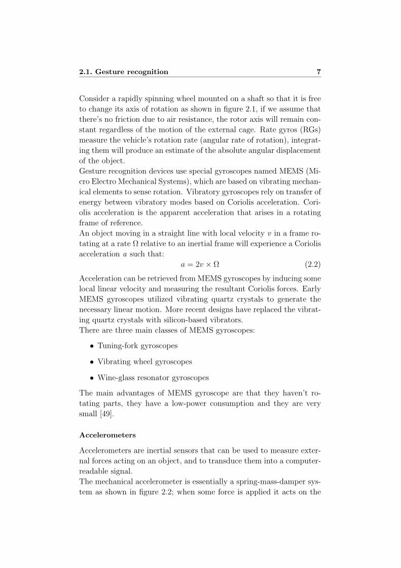
The mechanical accelerometer is essentially a spring-mass-damper sys-
tem as shown in figure 2.2; when some force is applied it acts on the
8Chapter 2. Mobile devices for gesture recognition: the state of
the art
mass and displaces the spring, according to the equation:
Fapplied = Finertial + Fdamping + Fspring = mx+ cx+ kx (2.3)
where c is the damping coefficient and k the spring’s elastic coefficient.
The main drawback of mechanical accelerometers is due to the non
Figure 2.2: Schema of a mechanical accelerometer
ideal performance of the spring; another issue is that this kind of device
is particularly sensitive to vibrations.
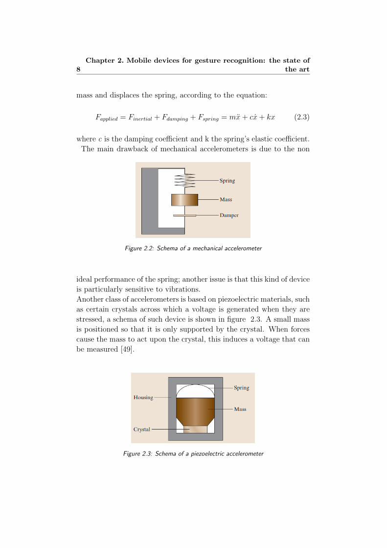
Another class of accelerometers is based on piezoelectric materials, such
as certain crystals across which a voltage is generated when they are
stressed, a schema of such device is shown in figure 2.3. A small mass
is positioned so that it is only supported by the crystal. When forces
cause the mass to act upon the crystal, this induces a voltage that can
be measured [49].
Figure 2.3: Schema of a piezoelectric accelerometer
2.1. Gesture recognition 9
IMU
An Inertial Measurement Unit (IMU) is a device that utilizes measure-
ment systems such as gyroscopes and accelerometers to estimate the
relative position, velocity and acceleration of an object in motion.
An IMU system provides a 6 DoF estimate of the pose: 3 for position
(x-y-z axis) and 3 for orientation (usually roll-pitch-yaw frame); com-
mercial IMUs also maintain estimates of velocity and acceleration.
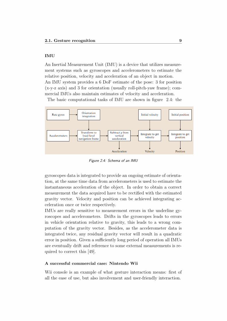
The basic computational tasks of IMU are shown in figure 2.4: the
Figure 2.4: Schema of an IMU
gyroscopes data is integrated to provide an ongoing estimate of orienta-
tion, at the same time data from accelerometers is used to estimate the
instantaneous acceleration of the object. In order to obtain a correct
measurement the data acquired have to be rectified with the estimated
gravity vector. Velocity and position can be achieved integrating ac-
celeration once or twice respectively.
IMUs are really sensitive to measurement errors in the underline gy-
roscopes and accelerometers. Drifts in the gyroscopes leads to errors
in vehicle orientation relative to gravity, this leads to a wrong com-
putation of the gravity vector. Besides, as the accelerometer data is
integrated twice, any residual gravity vector will result in a quadratic
error in position. Given a sufficiently long period of operation all IMUs
are eventually drift and reference to some external measurements is re-
quired to correct this [49].
A successful commercial case: Nintendo Wii
Wii console is an example of what gesture interaction means: first of
all the ease of use, but also involvement and user-friendly interaction.

10Chapter 2. Mobile devices for gesture recognition: the state of
the art
Gesture recognition is performed tanks to the Wii primary controller,
which has been realized in several different hardware configurations.
There are different Wii controllers, everyone with different specifica-
tions, but, generally speaking, Wii controllers for gesture recognition
consist of:
• accelerometer: ADXL300 or STMicroelectronics LIS3L02AL
which measure external forces applied on the controller;
• infrared optical sensor: allowing the console to determine
where the Wii Remote is pointing;
• gyroscope: a MEMS tuning-fork gyroscope, which support the
accelerometer and infrared optical sensor capabilities of Wii.
2.1.2 Biometrics signals for gesture recognition
Gesture recognition can be achieved processing biometrics signals pro-
duced by a human body performing a movement. There are various
biometrics signals that are useful for gesture recognition, they can be
summarized in three main classes:
• EOG (Electrooculography signals)
• EEG (Electroencephalographic signals)
• EMG (Electromyography signals)
This subsection describes the main projects carried out with these tech-
nologies, especially focusing on EMG signals employment as this is the
kind of signals uses in Eracle project.
EOG
Electrooculography (EOG) is a technique for measuring the resting
potential of the retina. The main applications are in ophthalmological
diagnosis and in recording eye movements. Since eye movements can
be tracked by modern technology with great speed and precision, they
can be used as a powerful input device, and have many practical appli-
cations in HCI [38]. EOG is one of the very few methods for recording
eye movements that does not require a direct attachment to the eye
itself.
Compared with EEG (see next subsection) EOG has a higher ampli-

2.1. Gesture recognition 11
Figure 2.5: Architecture of a EOG-based HCI system
tude, and the waveform is easier to detect. There are also some draw-
backs in the employment of this kind of signals: first of all the crosstalk
due to the facial muscles activity, secondly the noise produced by head
movements [24]. A schema of a typical HCI System based on EOG is
shown in figure 2.5.
EEG
An EEG signal is obtained directly through electrodes placed on the
scalp, it is a measurement of currents that flow during synaptic ex-
citations of the dendrites of neurons in the cerebral cortex. In fact
neurons communicate by means of electrical impulses and generate bio-
electromagnetic fields, that can be measured and analyzed in order to
detect a pattern corresponding to a movement [34].
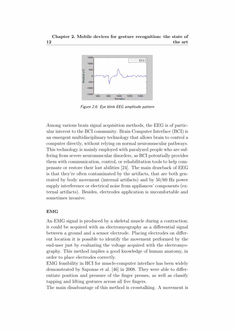
One of the most studied movements in EEG field is eye blink that can
be employed as a mouse click in a HCI application. Eye blink is easily
detected monitoring the signals of the prefrontal lobe because it has a
fixed pattern: a downward peak in the negative amplitude region shows
an eyes-open event, and then a positive peak shows an eyes-close event;
besides the amplitude of these peaks is higher compared to the normal
brain activity noticed with an EEG analysis.
A typical eye blink pattern is shown in figure 2.6.
Usually, the EEG signals acquired from the scalp are used to train an
Artificial Neural Network to perform a classification of the amplitude
pattern in order to recognize the movement executed by the user [28].
EEG technology is mainly applied in medical field, however some stud-
ies have been carried out in non-medical applications. [35].
12Chapter 2. Mobile devices for gesture recognition: the state of
the art
Figure 2.6: Eye blink EEG amplitude pattern
Among various brain signal acquisition methods, the EEG is of partic-
ular interest to the BCI community. Brain Computer Interface (BCI) is
an emergent multidisciplinary technology that allows brain to control a
computer directly, without relying on normal neuromuscular pathways.
This technology is mainly employed with paralyzed people who are suf-
fering from severe neuromuscular disorders, as BCI potentially provides
them with communication, control, or rehabilitation tools to help com-
pensate or restore their lost abilities [24]. The main drawback of EEG
is that they’re often contaminated by the artifacts, that are both gen-
erated by body movement (internal artifacts) and by 50/60 Hz power
supply interference or electrical noise from appliances’ components (ex-
ternal artifacts). Besides, electrodes application is uncomfortable and
sometimes invasive.
EMG
An EMG signal is produced by a skeletal muscle during a contraction;
it could be acquired with an electromyography as a differential signal
between a ground and a sensor electrode. Placing electrodes on differ-
ent location it is possible to identify the movement performed by the
end-user just by evaluating the voltage acquired with the electromyo-
graphy. This method implies a good knowledge of human anatomy, in
order to place electrodes correctly.
EMG feasibility in HCI for muscle-computer interface has been widely
demonstrated by Saponas et al. [46] in 2008. They were able to differ-
entiate position and pressure of the finger presses, as well as classify
tapping and lifting gestures across all five fingers.
The main disadvantage of this method is crosstalking. A movement is
2.1. Gesture recognition 13
not the result of a single muscle’s contraction, but the consequence of a
set of muscles working together; it entails that a single muscular fiber
takes part in more than just one movement making difficult the ges-
ture distinction task. The crosstalk problem is more significant when
the muscle activation is relatively weak, because the differential signal
obtained is very low; at a low level of contraction, a precise muscular
activity is hardly discernible from background activity [24]. Besides,
the EMG signal due to muscle contraction is not locally limited, but it
spreads the MUAP activation among the nearest muscular fibers.
The main application field of EMG is the medical one: with an EMG
analysis it could be possible to identify some muscular injury.
During the last few years EMG signals have become one of the most
promising and useful way to control prosthesis, especially for the limbs
amputation. Referring to this last field of application, it is important
to define the taxonomy of the movements that can be performed with
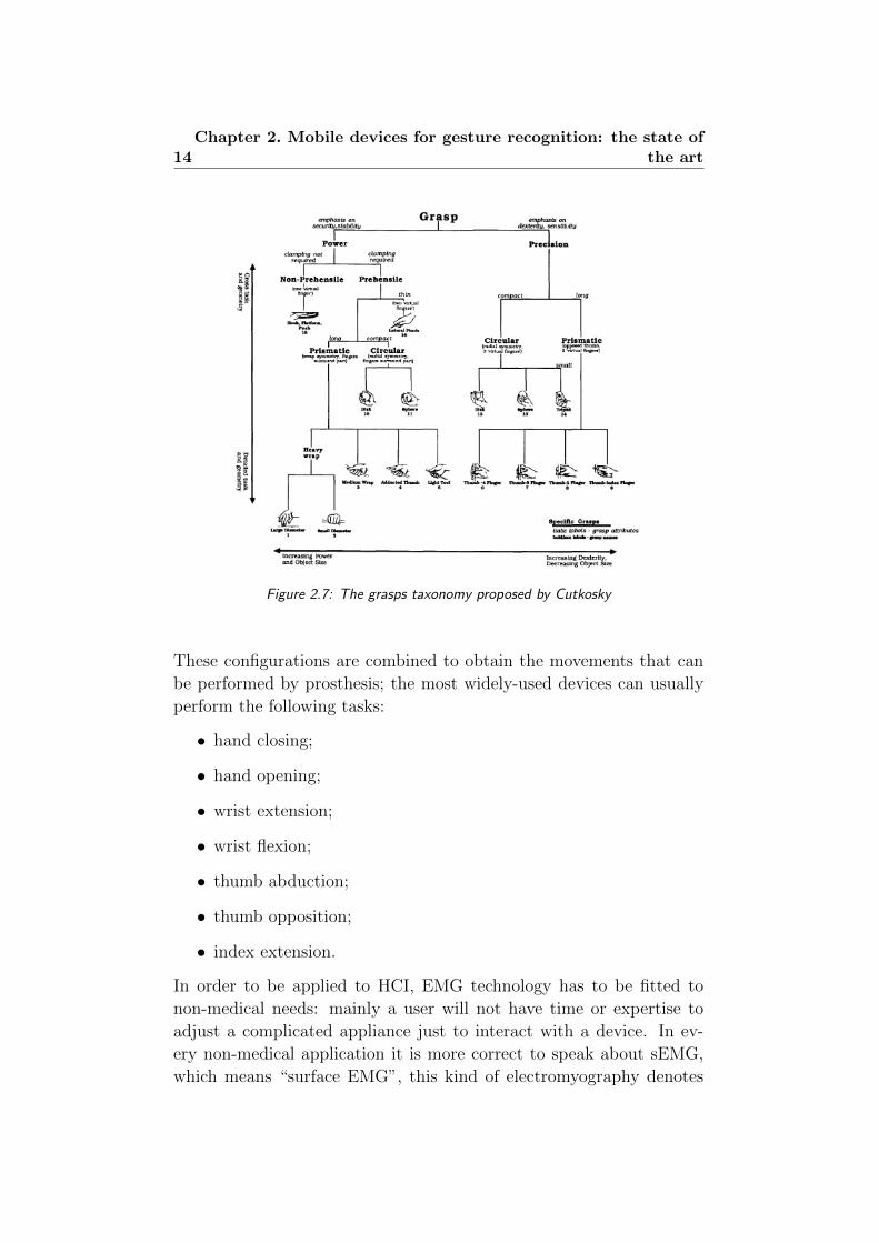
prosthesis. For grasps actions, the most widely-used taxonomy is the
one proposed in 1989 by Cutkosky [30], that is based on function ap-
proach. As shown in figure 2.7, Cutkosky identifies 16 different types
of grasps: observing the schema from left to right the grasps become
less powerful but more precise and the handled objects become smaller.
Usually upper limb prosthesis can’t replicate all the grasps described
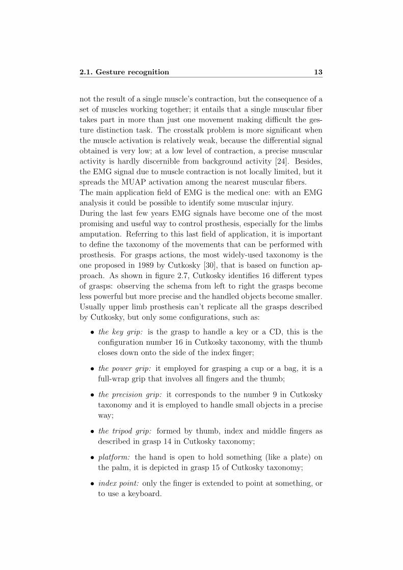
by Cutkosky, but only some configurations, such as:
• the key grip: is the grasp to handle a key or a CD, this is the
configuration number 16 in Cutkosky taxonomy, with the thumb
closes down onto the side of the index finger;
• the power grip: it employed for grasping a cup or a bag, it is a
full-wrap grip that involves all fingers and the thumb;
• the precision grip: it corresponds to the number 9 in Cutkosky
taxonomy and it is employed to handle small objects in a precise
way;
• the tripod grip: formed by thumb, index and middle fingers as
described in grasp 14 in Cutkosky taxonomy;
• platform: the hand is open to hold something (like a plate) on
the palm, it is depicted in grasp 15 of Cutkosky taxonomy;
• index point: only the finger is extended to point at something, or
to use a keyboard.
14Chapter 2. Mobile devices for gesture recognition: the state of
the art
Figure 2.7: The grasps taxonomy proposed by Cutkosky
These configurations are combined to obtain the movements that can
be performed by prosthesis; the most widely-used devices can usually
perform the following tasks:
• hand closing;
• hand opening;
• wrist extension;
• wrist flexion;
• thumb abduction;
• thumb opposition;
• index extension.
In order to be applied to HCI, EMG technology has to be fitted to
non-medical needs: mainly a user will not have time or expertise to
adjust a complicated appliance just to interact with a device. In ev-
ery non-medical application it is more correct to speak about sEMG,
which means “surface EMG”, this kind of electromyography denotes

2.1. Gesture recognition 15
that biometric signals are acquired using electrodes placed on the skin
surface, instead of a needle inserted through the skin directly into the
muscle fibers. Today there are many fields in which EMG signals are
employed, one of the most curious application is the work of Mandryk
et al. [40], which uses facial EMG signals as a way to identify human
emotional state.
Considering “traditional” movement recognition Wheeler et al. [53]
used EMG sensors on the forearm to recognize joystick movement.
Every EMG acquisition procedure consists in two main steps:
1. EMG data have been acquired with an electromyography and
features are extracted in order to recognize the movement per-
formed; for this task many methods can be applied: time-domain
statistics, short-time Fourier transform, wavelet and many more.
2. data are employed to train a classifier, which is able to match each
signal’s feature vector with a particular movement. The most
employed classifiers are Artificial Neural Networks and Support
Vector Machines.
Naik et al. [41, 43] have employed Independent Component Analysis
(ICA) in the first phase described above.
It is an iterative technique, where the only model of the signals is the
independence and the distribution, this class of algorithms has two
main advantages:
• source signals separation without there being any information on
the order of the sources;
• crosstalk and noise are substantially subsided.
When the source signals have been obtained, Root Mean Square has
been calculated for every set of movement performed. Then the feature
vectors obtained are classified with a feed forward back propagation
ANN, in order to recognize the movement executed by the end-user.
The gesture considered in these experiments are: flexion of the forearm,
abduction and flexion of wrist, adduction and flexion of wrist and finger
flexion while avoiding wrist flexion; the system described is able to
identify all these hand gestures, reaching a 100% accuracy result in
some cases.
In [42] Naik et al. compare the performance of four different ICA

16Chapter 2. Mobile devices for gesture recognition: the state of
the art
algorithms used for the movement recognition system described above.
The methods employed in this comparison are:
• TDSEP - Temporal Decorrelation Source Separation is
based on the simultaneous diagonalization of several time-delayed
correlation matrices;
• FastICA is a fixed point ICA algorithm that employs higher
order statistics for the recovery of independent sources;
• Infomax - Information Maximization algorithm is a gradient-
based neural network algorithm, with a learning rule for informa-
tion maximization;
• JADE - Joint Approximative Diagonalization of Eigen-
matrices is an algorithm based on the joint diagonalization of
cumulant matrices under the assumption that the sources have
non-Gaussian distribution (this is a requirement for ICA applica-
tion).
Figure 2.8: ICA algorithms performance comparison
The result of this comparison are shown in figure 2.8, the last bar
depicts the system’s performance using raw EMG, without any appli-
cation of ICA algorithm.
One of the most interesting applications of EMG-based HCI is mu-
CIs project by Microsoft Research [47, 48]. In this project sEMG are
used to distinguish among three different class of movements:
• hands-free finger gestures;

2.1. Gesture recognition 17
• hands-busy finger gestures;
• gestures for controlling a portable music player.
A desktop display guides the end-users through training session; it high-
lights the finger that has to been moved (for the first class of grips),
or shows the gesture to be performed, giving the user a visual feed-
back of his actions. EMG signals are acquired using a BioSemi Active
Two system; sensors are placed in a forearm muscle-sensing band (see
figure 2.9). The data acquired are splitted and converted in segments
Figure 2.9: Placement of the electrodes in Microsoft muCIs project
suitable for machine learning application. For every segment three set
of features are generated:
• Root Mean Square: correlates channel’s amplitude with mag-
nitude of muscle activity;
• Frequency Energy: computed through a FFT for each sample,
it is indicative of the temporal patterns of muscle activity;
• Phase Coherence: a measurement of the relationship among
EMG channels.
The feature vector acquired are employed to train a Support Vector
Machine, which obtains a good performance in gesture classification.
The main value of this application is that EMG signals analysis is

18Chapter 2. Mobile devices for gesture recognition: the state of
the art
employed in an every-day activity like pause a CD-player. Future di-
rections of these projects are the creations of a low-power wireless pro-
totype muscle-sensing unit and the employment of this device for video
game interface.
An interesting demonstrative video regarding this muCIs device can be
found at the project’s main page [15].
2.1.3 Image analysis for gesture recognition
Vision identification devices have been successfully developed for ges-
ture recognition system. These devices use cameras to identify the user
gestures - applying image synthesis and analysis algorithms [31] - and
provide a visual feedback through a projector or a monitor.
The main advantage of this technology is that it can avoid wearing
electrodes or sensor band, moreover, the use of a depth-sensing camera
facilitates precise 3D hand positioning and gesture-tracking without
requiring the user to wear any type of on-body sensors. However, these
devices have several drawbacks; first, they require observable move-
ment or interaction that can be “socially awkward”, secondly they are
relatively sensitive to environment’s light and noise. Moreover, finger
contact pressure is not robustly measurable with a camera.
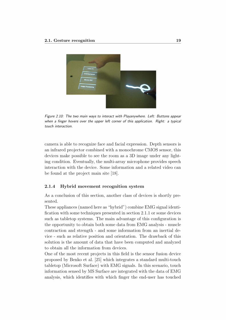
One of the most interesting applications in this field is PlayAnywhere
system by Wilson [54], this is a front-projected computer vision-based
interactive table system, which uses a compact commercial projection
system. The device is composed by a NEC WT600 DLP projector to
project a 40” diagonal image onto an ordinary table surface and an
infrared light source. A user employs hovers and touches to interact
with the device, such features are extracted using a technique which
exploits the change in appearance of shadows as an object approaches
the surface. The main advantages of this approach are: first of all this
input procedure doesn’t rely on special instrumentation of the surface,
secondly this solution extends the “interaction vocabulary” available
for this devices (see figure 2.10).
One of the most innovative device in this field has been recently pre-
sented by Microsoft with the code name “project Natal”. It is a
controller-free device, which combine an RGB camera, depth sensor,
multi-array microphone and custom processor running proprietary soft-
ware.
The whole system is able to track a player’s movement in 3D. The RGB
2.1. Gesture recognition 19
Figure 2.10: The two main ways to interact with Playanywhere. Left: Buttons appear
when a finger hovers over the upper left corner of this application. Right: a typical
touch interaction.
camera is able to recognize face and facial expression. Depth sensors is
an infrared projector combined with a monochrome CMOS sensor, this
devices make possible to see the room as a 3D image under any light-
ing condition. Eventually, the multi-array microphone provides speech
interaction with the device. Some information and a related video can
be found at the project main site [18].
2.1.4 Hybrid movement recognition system
As a conclusion of this section, another class of devices is shortly pre-
sented.
These appliances (named here as “hybrid”) combine EMG signal identi-
fication with some techniques presented in section 2.1.1 or some devices
such as tabletop systems. The main advantage of this configuration is
the opportunity to obtain both some data from EMG analysis - muscle
contraction and strength - and some information from an inertial de-
vice - such as relative position and orientation. The drawback of this
solution is the amount of data that have been computed and analyzed
to obtain all the information from devices.
One of the most recent projects in this field is the sensor fusion device
proposed by Benko et al. [25] which integrates a standard multi-touch
tabletop (Microsoft Surface) with EMG signals. In this scenario, touch
information sensed by MS Surface are integrated with the data of EMG
analysis, which identifies with which finger the end-user has touched
20Chapter 2. Mobile devices for gesture recognition: the state of
the art
the tabletop. In this way, the “interaction vocabulary” available to in-
teractive surface systems is extended with the opportunity of detecting
(theoretically) ten different finger’s touches instead of one single touch.
Moreover the whole system is provided with the information of fingers’
movement when the user is not currently touching the tabletop surface.
Another mixed approach is described in [45]: in this project a video-
game control device acquires EMG signals and acceleration data from
the forearm. Analyzing the EMG signal, the force exerted by the user
can be measured and used as input signal, even when there is no ex-
plicit movement of the forearm. Besides, the device can classify hook
and straight punch motions of the forearm by analyzing the accelera-
tion data.
This device can be easily adopted in a action virtual-reality game, the
user can intuitively make various punching motions, such as punch-like
or upper cut-like motion; besides, by measuring EMG signals it is pos-
sible to identify some “special attack” completely activated by muscle
contraction.
The last cited application is described in [37]: it uses both EMG sig-
nals and accelerometer for recognizing some word in German Sign Lan-
guage, which is a communication way for hearing-impaired people. In
this case, the accuracy of the system is essential. For recording a
dataset, an Alive Heart Monitor has been employed - which originally
is a device for electrocardiogram measures - and a 3-axis accelerome-
ter has been placed on the user’s forearm. The Alive system has been
attached nearby wrist, for measuring EMG signal generated by Flexor
Carpi Radialis.
For recording the most important features from the accelerometer, a
4-order low-pass Butterworh filter and some common statistical fea-
tures (such as RMS) are calculated on the data obtained. The same
Butterworth filter is applied to the EMG signal, followed by the calcu-
lation of fundamental frequency and Fourier variance of the spectrum
obtained with a Fast Fourier Transform. The obtained feature vectors
are classified with Support Vector Machines and k-Nearest Neighbor
classifier.
Using the most relevant 15 features, an average accuracy of 99.82% is
achieved only for subject-dependent recognition; but this high accu-
racy doesn’t carry over to the subject-independent recognition.
Create a gesture recognition device that is subject-independent is one

2.1. Gesture recognition 21
of the future direction of this kind of research.
22Chapter 2. Mobile devices for gesture recognition: the state of
the art
2.2 Mobile devices
In this second section a summary of mobile devices technology is pre-
sented.
This part is divided in two main topics: an overview of the main CPU
and hardware suitable for mobile application and some hint regarding
OS used in smart devices.
2.2.1 CPUs and hardware
CPUs are the main core of all digital platforms. In order to be employed
on a mobile device, a CPU must be both efficient and small. This
section provides a summary of the most used platforms and CPUs
for mobile devices; some of these microcontrollers have been directly
employed in Eracle project before adopting Nvidia Tegra.
PIC and dsPIC
PIC (Programmable Interface Controller) is a family of Harvard ar-
chitecture microcontrollers. They have been originally developed by
General Instrument; nowadays one of the most important manufac-
turer in this field is Microchip Technology [14].
These devices are employed both by professional developers and hob-
byists, due to their low costs, serial programming capability, large user
base and availability of free development tools like MPLab IDE.
Four configurations of microcontrollers are usually employed: 8-bit, 16-
bit, 24-bit and 32-bit. Microchip also developed a particular class of
microcontrollers named DSPic, which combines control features of a
microcontroller with the computation throughput of a Digital Signal
Processing. These characteristics allow developers to employ libraries
specific for signal processing, making computation more efficient.
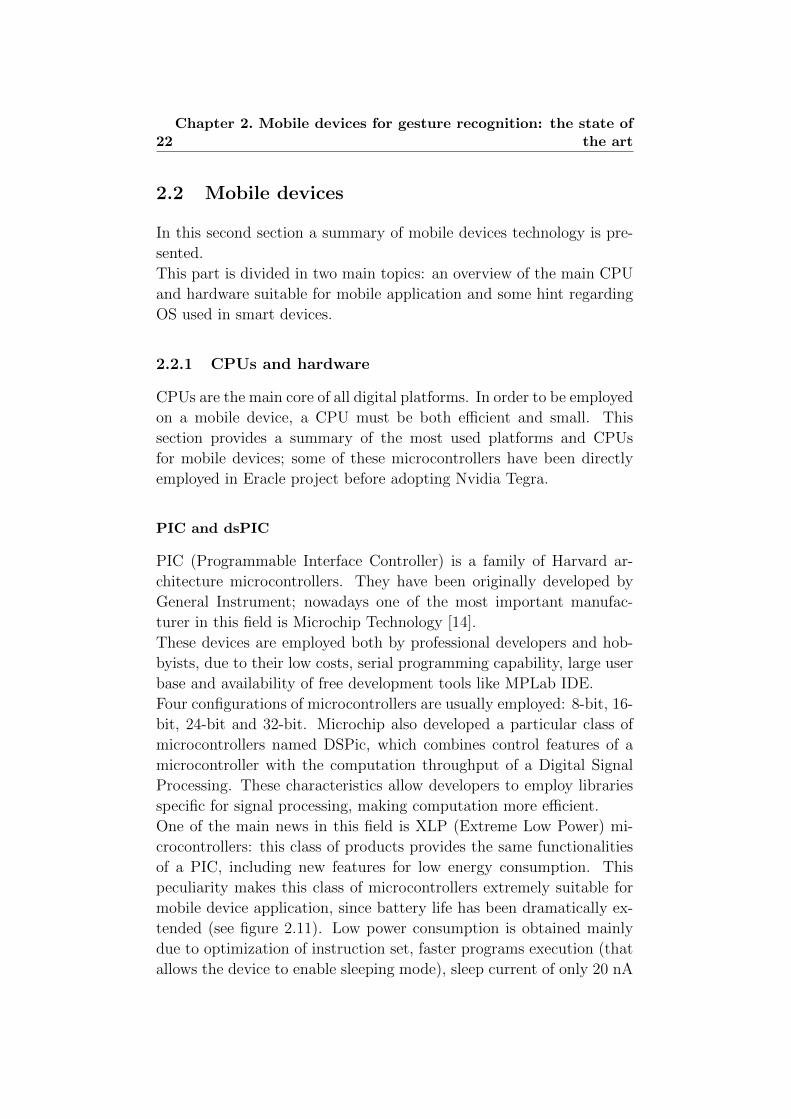
One of the main news in this field is XLP (Extreme Low Power) mi-
crocontrollers: this class of products provides the same functionalities
of a PIC, including new features for low energy consumption. This
peculiarity makes this class of microcontrollers extremely suitable for
mobile device application, since battery life has been dramatically ex-
tended (see figure 2.11). Low power consumption is obtained mainly
due to optimization of instruction set, faster programs execution (that
allows the device to enable sleeping mode), sleep current of only 20 nA
2.2. Mobile devices 23
and deactivation of unused peripherals.
PIC is employed in many fields, for example:
• automotive;
• intelligent power supply;
• motor control solutions;
• mechatronics;
• battery management solutions;
• utility metering solutions;
• touch screen controllers.
Figure 2.11: Battery life improvement on a PIC24 employing XLP technology
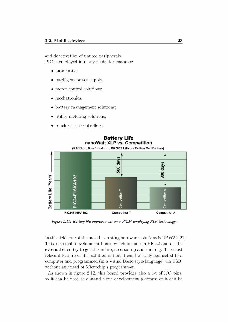
In this field, one of the most interesting hardware solutions is UBW32 [21].
This is a small development board which includes a PIC32 and all the
external circuitry to get this microprocessor up and running. The most
relevant feature of this solution is that it can be easily connected to a
computer and programmed (in a Visual Basic-style language) via USB,
without any need of Microchip’s programmer.
As shown in figure 2.12, this board provides also a lot of I/O pins,
so it can be used as a stand-alone development platform or it can be
24Chapter 2. Mobile devices for gesture recognition: the state of
the art
Figure 2.12: UBW board
connected with other appliances to carried out a control device.
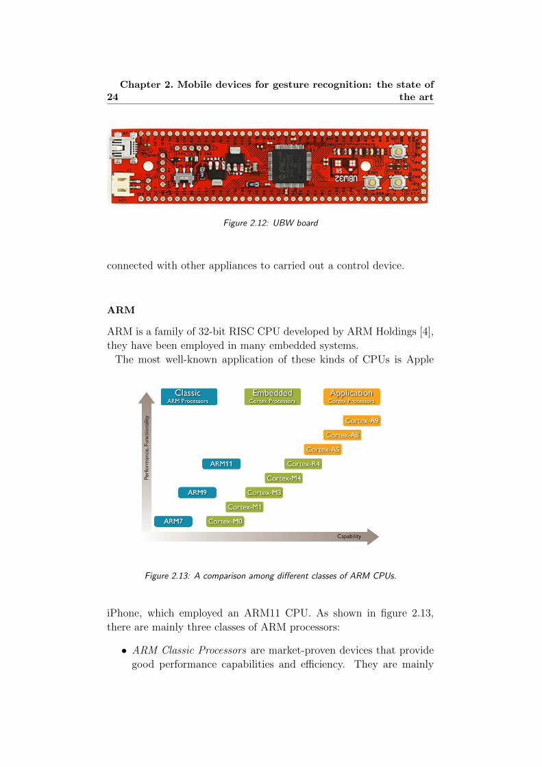
ARM
ARM is a family of 32-bit RISC CPU developed by ARM Holdings [4],
they have been employed in many embedded systems.
The most well-known application of these kinds of CPUs is Apple
Figure 2.13: A comparison among different classes of ARM CPUs.
iPhone, which employed an ARM11 CPU. As shown in figure 2.13,
there are mainly three classes of ARM processors:
• ARM Classic Processors are market-proven devices that provide
good performance capabilities and efficiency. They are mainly
2.2. Mobile devices 25
employed in consumer and home applications.
• ARM Cortex Embedded Processors are also divided in two main
classes: M-series CPUs have been originally developed for mi-
crocontroller domain, therefore they provide highly determinis-
tic interrupt management and low power consumption; they are
mainly employed in signal processing devices and smart sensors.
R-Series processors have been developed for real-time applica-
tions, therefore they ensure strong compatibility with existing
platforms; they are mainly employed in automotive braking sys-
tem and mass storage controller.
• ARM Cortex Application Processors are designed for mobile Inter-
net devices, they provide a performance of up to 2GHz in single-
core or multi-core architecture. This class of CPUs is also sup-
plied with advanced Floating Point execution units and a new
technology for multimedia processing called NEON. ARM Cor-
tex Application Processors are mainly employed in smartphones,
eBooks readers and digital TV.
In Eracle project Nvidia Tegra has been employed (see section 5.1) ,
which combines Dual-core ARM Cortex-A9 MPCore processor and 3D
graphics processor. Nvidia Tegra is one of the most employed CPU for
mobile devices, it is a full HD ultra low-power mobile Web processor,
mainly used for:
• tablets;
• mobile Internet devices;
• smartphones;
• portable media players;
• Internet TV;
• automotive.
Due to the high graphic performance of this CPU, it is also employed
in game and graphics design applications.
Today Tegra is distributed for developers as a basic motherboard com-
prises Tegra 250 SoC and a range of ports for peripherals. Specific SDK
for developing with Windows CE or Android are available on Tegra web
site [17].

26Chapter 2. Mobile devices for gesture recognition: the state of
the art
Arduino
Arduino is an open-source electronics prototyping platform based on
flexible, easy-to-use hardware and software.
There are many versions of Arduino board, one for each need. The
main configurations are [2]:
• Duemilanove: it is the basic Arduino USB board (see figure 2.14),
that can be easily programmed by connecting it to a computer
with an USB cable;
• Bluetooth: it contains a Bluetooth module that allows wireless
communication and programming;
• Mini: it is the most suitable solution for embedded systems, due
to its small dimensions;
• LilyPad: it is designed for wearable devices, this platform can
be sewn onto fabric;
• Fio: it is the Arduino board designed to work with wireless sig-
nals, it includes a socket for XBee radio, connector for LiPo bat-
tery, and integrated battery charging circuitry.
Figure 2.14: Arduino Duemilanove board
Arduino boards mainly uses Atmel ATmega328, an High Performance
and Low Power consumption AVR 8-Bit Microcontroller [5].
2.2. Mobile devices 27
2.2.2 Operative system
Design an operative systems for a mobile device is a difficult task,
mainly because it must handle the “usual” OS activities but in a min-
imum space and (usually) with reduced software library available.
In this section two main operative systems are presented: Windows
CE by Microsoft and Android, the most well-known open source OS
for mobile devices.
Windows CE
Windows CE is the smallest Microsoft Windows Operation System: it
is a ROM-based OS with a Win32 subset API.
Since version 4.1 it supports .NET Compact Framework, a version
of the .NET runtime for mobile and embedded devices. The Com-
pact Framework provides the same powerful .NET runtime environ-
ment with a smaller class library.
Windows CE, at its first version (1.0), was just a simple organizer op-
erating system; the second version was released in 1997 with the intro-
duction of the Handheld PC 2.0. The new version included Windows
standard network functions, a Network Driver Interface Specification
(NDIS) miniport driver model, and a generic NE2000 network card
driver, it was also the first edition of the OS to be also available sep-
arately from a specific mobile device. In Windows CE 2.01, the C
runtime library was moved from a statically linked library attached to
each EXE and DLL into the operating system itself. This change lead
to a sensible reduction of the size of both the operating system and the
applications themselves.
In mid-2000 Windows CE 3.0 was released, the most important feature
of this version was its kernel: it was optimized for real-time application
and it allowed nested interrupt. There was also many other news in
Windows CE 3.0, such as: full COM and DCOM support, file size in-
creased to 32 MB per file, media player control, XML support, remote
desktop display support and the introduction of the DirectX API.
The release of Windows CE 4.2 in 2003 was very important for mobile
devices, in fact this edition provided: PC-specific APIs that support
menu bars, soft input panel and the introduction of hardware paging
tables.
The latest release of this OS is Windows CE 6.0, this edition includes
28Chapter 2. Mobile devices for gesture recognition: the state of
the art
some features highly oriented to mobile technologies, such as smart-
phones and mobile phones. Just as hints, this release includes: MS
Silverlight, Embedded Internet Explorer and touch screen support [26].
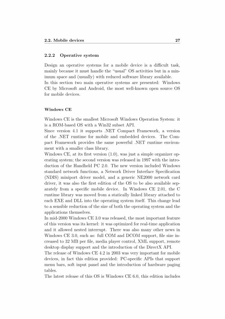
Some of the most important changes in Windows CE concern its archi-
Figure 2.15: Architecture of Windows CE 6.0
tecture and kernel. As shown in figure 2.15, the OS is mainly splitted
in two subsystems: user virtual machine and kernel virtual machine.
Until Windows CE 6.0, file system, device manager and graphics sub-
system were separated (they were named FileSys.EXE, Device.EXE
and GWES respectively) and they operated in user mode. This sepa-
ration made the system robust - since every subsystem was independent
and protected from one other - but also decreased performance (due to
many process switching).
The new architecture brings all the subsystem into the kernel virtual
machine, improving system performance and communication among
these three basic processes.
Nk.exe contains the OEM abstraction layer code and a compatibil-
ity layer, therefore kernel can be updated without affected OEM code.
The DLL named k.Coredll.dll mimics the old Coredll.dll (that was orig-
inally placed in user virtual machine) and helps with porting tasks from
old applications. A call to an API that requires Coredll is redirect to
k.Coredll.dll that simply reflects the request to kernel.dll for process-
ing; as the calls are all within kernel virtual machine, the overall per-
formance is sensibly improved.
The user mode drivers section provides support for third-party drivers

2.2. Mobile devices 29
execution, this allocation reduces the process performance but improves
security [22].
There are many applications that are suitable for this OS [23]:
• scanners;
• RFID readers;
• eBook readers;
• GPS devices;
• game controllers;
• VoIP phones;
• multimedia portable devices.
One of the most interesting features of Windows CE 6.0 is that it can be
flashed on NVIDIA Tegra 250 Developer Kit described in section 2.2.1.
This feature make possible to develop applications running on NVIDIA
Tegra without handle with hardware or low-level programming.
Android
Android is an open-source operative system for mobile devices, it is
based on Linux Kernel version 2.6.
Applications running on Android can be simply developed using Java
language.
Android employed Dalvik Virtual Machine, which is an optimized JVM
for mobile devices to ensure high compatibility. Moreover, it includes
media support for common audio, video, and still image formats (MPEG4,
H.264, MP3, AAC, AMR, JPG, PNG, GIF), other than SQLite for
structured data storage and modules for wireless communication like
Bluetooth and Wi-Fi.
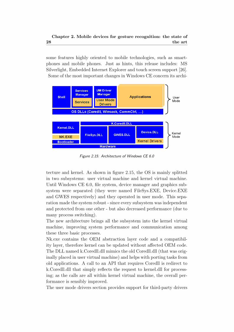
The main architecture of Android is shown in figure 2.16.
The first layer includes the main application of a mobile device like
a Smartphone: email client, Internet browser, organizer, phone and
many more. The Application Framework layer provides the underlying
services of all applications that are also available to developers. These
services are:
• View system: which includes a set of Views that can be used in
building application, such as lists, grids, text boxes and more;
30Chapter 2. Mobile devices for gesture recognition: the state of
the art
• Content Providers that allows an application to access data on
another computer, or shares its own information;
• Notification Manager which schedules custom alerts;
• Activity Manager that manages the lifecycle of application run-
ning on the platform.
The third layer consists of a set of C/C++ libraries, which are both
used by Android application and exposed to developers. Some of the
most important features are System Libraries (System C libraries tuned
for embedded Linux-based devices), Media Libraries (designed to han-
dle different media files) and SQLite, which allow the use of databases
on smart devices. Android Runtime layer include a set of core libraries
- that provides a set of functionalities of Java programming language
- and Dalvik Virtual Machine, which ensure the compatibility of Java
code, adding some features especially designed for mobile devices.
Last layer is Linux Kernel which handle services such as security,
Figure 2.16: Architecture of Android
process management, network stack and driver management.
2.2. Mobile devices 31
Due to open-source license and the ease of use of Java code, Android
has been used in many portable devices. The first smart device run-
ning Android was T-Mobile G1 from HTC, developed in 2008. In the
last year some devices such as HTC Desire and Samsung Galaxy S
employed Android with high technologies CPUs and hardware [1].

32Chapter 2. Mobile devices for gesture recognition: the state of
the art
Chapter 3
Project plan and description
“Kirk: All I ask is a tall ship and a star to steer her by.
You could feel the wind at your back in those days. The sounds of the sea
beneath you. And even if you take away the wind and the water it’s still the
same... the ship is in yours. You can feel her. And the stars are still here.”
The ultimate computer
Star Trek - The original series
This chapter discusses the aims of Eracle project, the gestures that
are employed for Human Computer Interaction and outlines the main
differences between this project and previous implementations of EMG-
based recognizer devices. It gives reasons for our choices regarding
EMG signals as input data and Nvidia Tegra as the computing core of
the project.
The last section introduces the general architecture of Eracle, that will
be detailed described in chapter 6.
3.1 Project goals
Eracle is a mobile device that recognizes some basic hand gestures pro-
cessing the EMG signals generated by the forearm muscles.
Recognizers based on EMG signals are usually employed in biomedi-
cal field to control prosthesis. Eracle project has a different goal: it
is mainly designed to interact with Virtual Reality environments, like
video games or augmented reality simulations. With like Eracle, the
user can interact directly by its movements, without employing a key-
board or a mouse, making the simulation more immersive. This latter
consideration is also supported by the commercial success of devices
34 Chapter 3. Project plan and description
like Nintendo Wii or Microsoft Natal. In the first appliance, the con-
troller is mainly employed to track the position of the user’s hand, in
the second one there isn’t any controller at all, since the user gestures
are directly identified thanks to image processing algorithms.
It is important that the recognized movement emulates some gestures
that are “intuitive” for a user. This consideration is especially true for
video games: the user should perform natural and spontaneous ges-
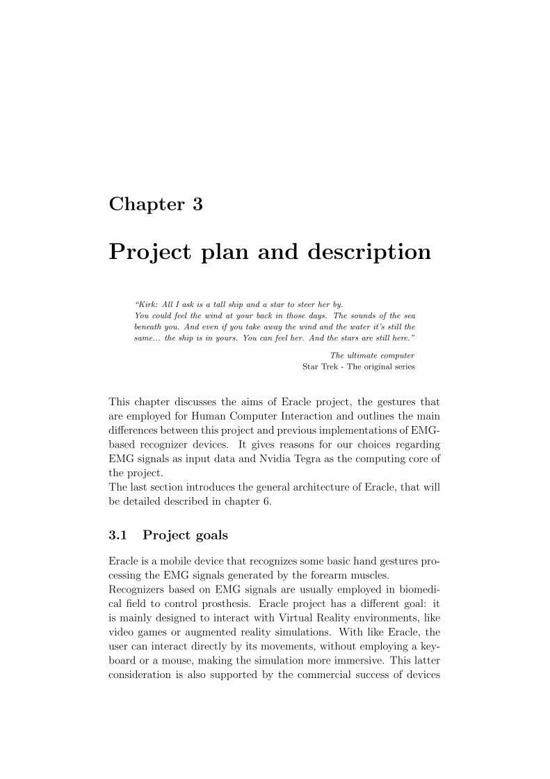
tures to control his avatar. An example of a special charged attack in
Figure 3.1: Typical motion for a charged attack in Muscleman project
an action games is shown in figure 3.1, this movement is recognized by
the Muscleman device proposed by Park and Kim in [45]. Muscleman
has been previously described in section 2.1.4.
Eracle project could be employed in Virtual Reality simulation to track
the user’s movement. Moreover, it could be connected to a Virtual Re-
ality helmet that provides the visual feedback to the user. The devkit
described in section 5.1 provides both USB and Ethernet port, so it
could be easily linked to a wide range of appliances.
The sampling devices that provide the input data to the computing
core are completely integrated in the acquisition glove (see chapter 6,
section 6.2, for more information) that could be worn by individuals
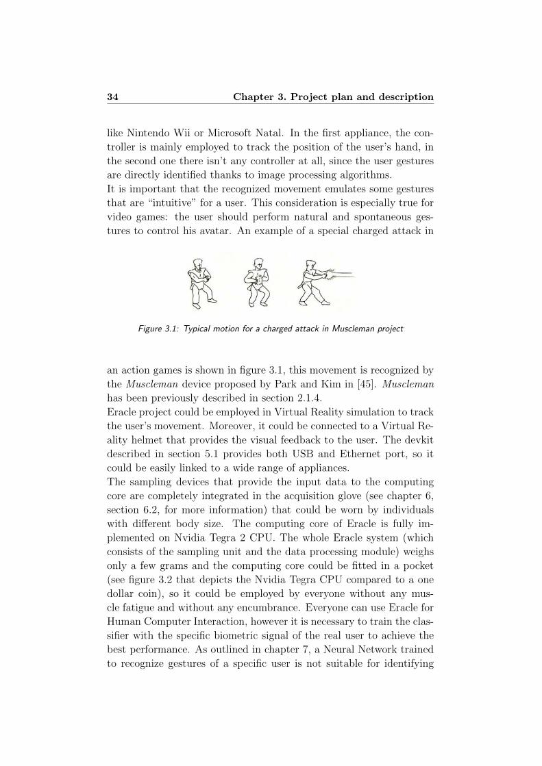
with different body size. The computing core of Eracle is fully im-
plemented on Nvidia Tegra 2 CPU. The whole Eracle system (which
consists of the sampling unit and the data processing module) weighs
only a few grams and the computing core could be fitted in a pocket
(see figure 3.2 that depicts the Nvidia Tegra CPU compared to a one
dollar coin), so it could be employed by everyone without any mus-
cle fatigue and without any encumbrance. Everyone can use Eracle for
Human Computer Interaction, however it is necessary to train the clas-
sifier with the specific biometric signal of the real user to achieve the
best performance. As outlined in chapter 7, a Neural Network trained
to recognize gestures of a specific user is not suitable for identifying
3.1. Project goals 35
Figure 3.2: Nvidia Tegra compared to a one dollar coin. This SoC easily fit in a pocket
the movements performed by another one. This is mainly due to the
differences of arm size, sweating and muscle strength.
However - provided that the system has been set up with the appropri-
ate classifier - it could be employed by different users simply by wearing
the acquisition glove on the forearm.
This device could also be employed to control a simple program run-
ning on a PC; for example the close hand movement could identify a
user assertion (like the OK button in a dialog box) and an open hand
gesture could represents the user refusal (like the Cancel button in a
dialog box).
Recent works (such as [29]) describes how devices like Eracle can di-
rectly interact with robotic arm; this last application field could be
interesting especially in an industrial context. However, it is necessary
to improve the global performance in order to apply Eracle to an in-
dustrial assembly line.
Another employment field of Eracle is home automation: each gesture
would be used to control a domestic appliance like television or air-
conditioner. As discussed in section 3.2, EMG-based recognizers are
more suitable than image-based devices for this field of application, as
they avoid the installation of many cameras in the user’s home.

36 Chapter 3. Project plan and description
3.1.1 Recognized gestures
Eracle is currently able to recognize up to five movements with accuracy
about 90%; however - as described in chapter 8, section 8.1 - we think
that the number of recognized gestures could be increased, as well as
the global success rate of the device.
The five gestures recognized by Eracle are:
Close Hand
All fingers are clenched into a fist, as shown in figure 3.3. This gesture
could represent a user’s assertion in typical PC interaction, or an attack
movement in a video game application.
Figure 3.3: Close hand movement
Wrist extension
The fingers are stretched and the hand is flexed towards the back, as
shown in figure 3.4. This gesture could be employed to scroll some
pictures clockwise.
Figure 3.4: Wrist extension movement
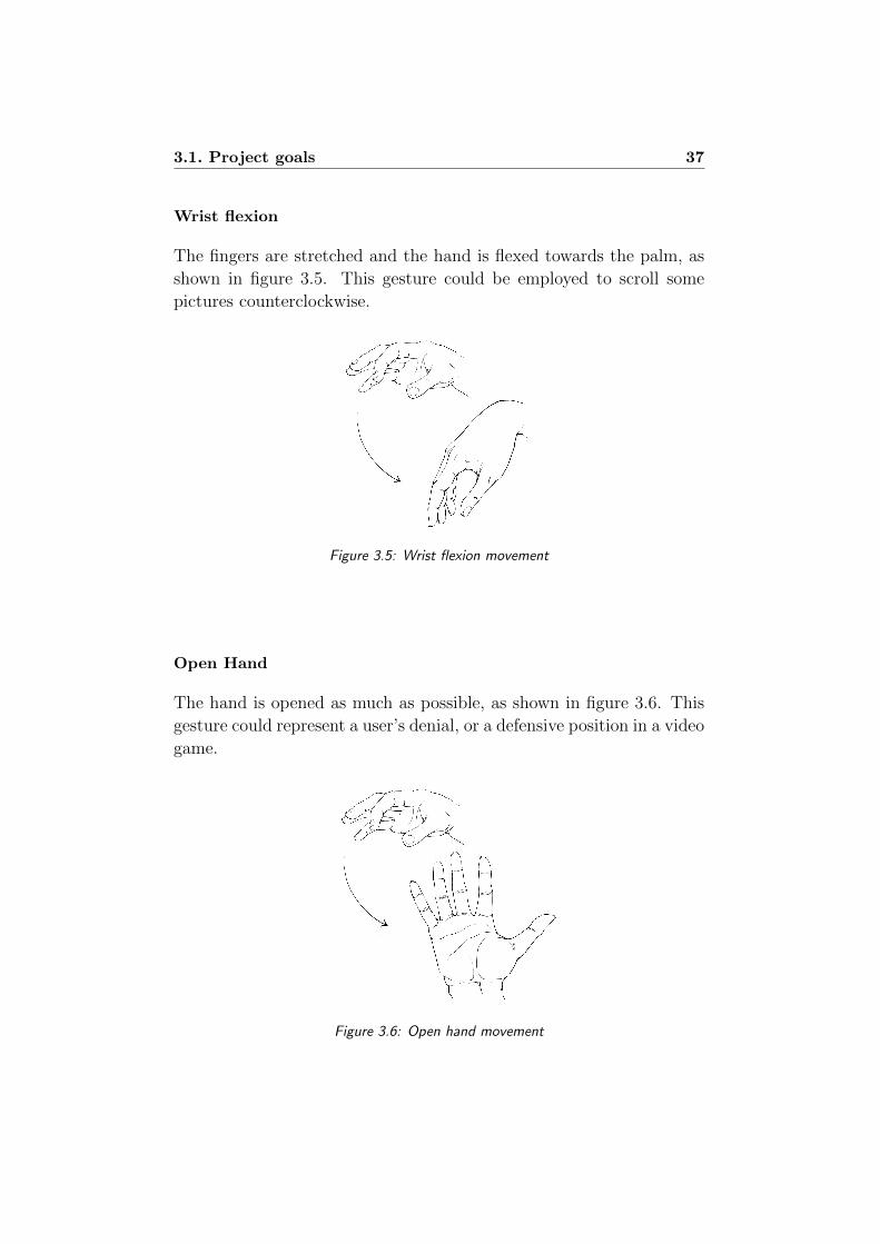
3.1. Project goals 37
Wrist flexion
The fingers are stretched and the hand is flexed towards the palm, as
shown in figure 3.5. This gesture could be employed to scroll some
pictures counterclockwise.
Figure 3.5: Wrist flexion movement
Open Hand
The hand is opened as much as possible, as shown in figure 3.6. This
gesture could represent a user’s denial, or a defensive position in a video
game.
Figure 3.6: Open hand movement
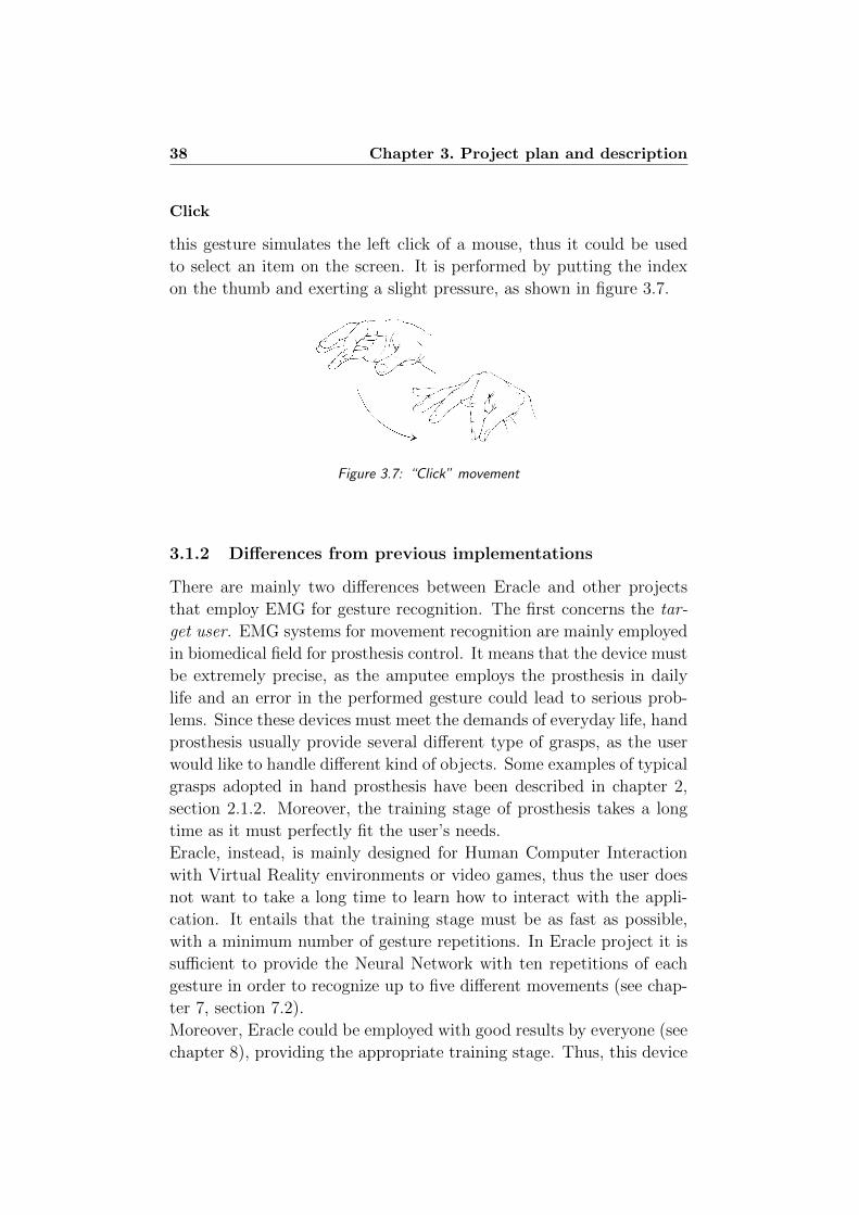
38 Chapter 3. Project plan and description
Click
this gesture simulates the left click of a mouse, thus it could be used
to select an item on the screen. It is performed by putting the index
on the thumb and exerting a slight pressure, as shown in figure 3.7.
Figure 3.7: “Click” movement
3.1.2 Differences from previous implementations
There are mainly two differences between Eracle and other projects
that employ EMG for gesture recognition. The first concerns the tar-
get user. EMG systems for movement recognition are mainly employed
in biomedical field for prosthesis control. It means that the device must
be extremely precise, as the amputee employs the prosthesis in daily
life and an error in the performed gesture could lead to serious prob-
lems. Since these devices must meet the demands of everyday life, hand
prosthesis usually provide several different type of grasps, as the user
would like to handle different kind of objects. Some examples of typical
grasps adopted in hand prosthesis have been described in chapter 2,
section 2.1.2. Moreover, the training stage of prosthesis takes a long
time as it must perfectly fit the user’s needs.
Eracle, instead, is mainly designed for Human Computer Interaction
with Virtual Reality environments or video games, thus the user does
not want to take a long time to learn how to interact with the appli-
cation. It entails that the training stage must be as fast as possible,
with a minimum number of gesture repetitions. In Eracle project it is
sufficient to provide the Neural Network with ten repetitions of each
gesture in order to recognize up to five different movements (see chap-
ter 7, section 7.2).
Moreover, Eracle could be employed with good results by everyone (see
chapter 8), providing the appropriate training stage. Thus, this device
3.1. Project goals 39
is suitable for different individuals, with different physique and weight;
on the contrary, prosthesis is designed and trained to perfectly fit only
one user’s needs. This entails that prosthesis is able to recognize more
movements and different grasps; instead Eracle can only recognize some
basic gestures that make the Human Computer Interaction simpler.
The second main difference between Eracle and the typical applica-
tion field of EMG concerns the hardware devices employed to perform
the classifier’s training.
The signal processing stage of Eracle is fully developed on the Nvidia
Tegra 2 (described in chapter 5 section 5.1) that is a powerful and
efficient SoC, but it provides the computing performance of a Smart-
phones CPU. Instead, almost all the projects focusing on EMG signal
analysis employ Desktop PC for data processing. These workstations
provide superior speed performance, that entails improved accuracy for
gesture recognition tasks.
In developing Eracle, we have mainly focused on system’s accuracy in
recognizing the performed movement. All the modules of the com-
puting core have been designed to be as independent as possible; this
choice is perfect for debug purposes (as we can easily check input and
output values of each unit), but leads to an increase in computational
speed. However, in chapter 8, section 8.1 we propose some future de-
velopments that will shorten the processing time.
40 Chapter 3. Project plan and description
3.2 Technological choices: EMG and mobile de-
vices
The two keywords of Eracle project are electromyogram signals and
mobile devices, as we have developed a device that recognize hand
gestures processing the EMG signals sampled from the muscles, but
this appliance must be small enough to be worn by the user.
There are many classes of signals that can be employed to identify the
user’s movement, and there are also many different devices that can be
employed to achieve this purpose. We have decided to employ EMG
signals as input data and Nvidia Tegra as computing device, the next
paragraph provides some reasons of our choices.
3.2.1 EMG
As discussed in the previous chapter (see section 2.1.2) there are mainly
three classes of algorithms that are employed in gesture recognition:
EMG, EEG and image analysis techniques. There are some advantages
and some drawbacks in all the three cited approaches:
• EEG: they provide a huge amount of information about the user
movements, as all the signals are sampled directly from the scalp
and there is no crosstalking generated by muscles contractions.
However this kind of biometric signals are affected by artifacts,
moreover, setting up an EEG acquisition procedure is a difficult
task, as the electrodes must be placed directly on the user’s head,
making this acquisition method unsuitable for a mobile applica-
tion (see figure 3.8).
• EMG: these signals are generated by muscles contraction; as a
movement is usually performed by several muscles working to-
gether this method is affected by signal overlapping called crosstalk-
ing. This problem can be avoided employing needle electrodes
(that are actually used in medical examinations), but they are
totally unsuitable for a Virtual Reality or a Human Computer
Interaction application.
With this technique is possible to recognize about four or five
basic movements.
• Image analysis techniques: this kind of devices have been
recently employed for a game controller based on gesture recog-
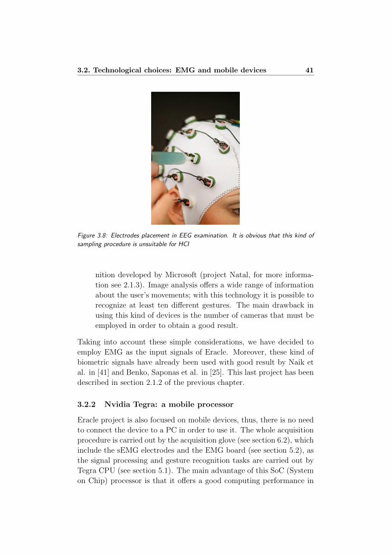
3.2. Technological choices: EMG and mobile devices 41
Figure 3.8: Electrodes placement in EEG examination. It is obvious that this kind of
sampling procedure is unsuitable for HCI
nition developed by Microsoft (project Natal, for more informa-
tion see 2.1.3). Image analysis offers a wide range of information
about the user’s movements; with this technology it is possible to
recognize at least ten different gestures. The main drawback in
using this kind of devices is the number of cameras that must be
employed in order to obtain a good result.
Taking into account these simple considerations, we have decided to
employ EMG as the input signals of Eracle. Moreover, these kind of
biometric signals have already been used with good result by Naik et
al. in [41] and Benko, Saponas et al. in [25]. This last project has been
described in section 2.1.2 of the previous chapter.
3.2.2 Nvidia Tegra: a mobile processor
Eracle project is also focused on mobile devices, thus, there is no need
to connect the device to a PC in order to use it. The whole acquisition
procedure is carried out by the acquisition glove (see section 6.2), which
include the sEMG electrodes and the EMG board (see section 5.2), as
the signal processing and gesture recognition tasks are carried out by
Tegra CPU (see section 5.1). The main advantage of this SoC (System
on Chip) processor is that it offers a good computing performance in
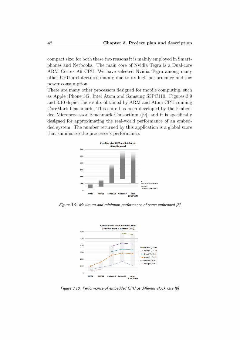
42 Chapter 3. Project plan and description
compact size; for both these two reasons it is mainly employed in Smart-
phones and Netbooks. The main core of Nvidia Tegra is a Dual-core
ARM Cortex-A9 CPU. We have selected Nvidia Tegra among many
other CPU architectures mainly due to its high performance and low
power consumption.
There are many other processors designed for mobile computing, such
as Apple iPhone 3G, Intel Atom and Samsung S5PC110. Figures 3.9
and 3.10 depict the results obtained by ARM and Atom CPU running
CoreMark benchmark. This suite has been developed by the Embed-
ded Microprocessor Benchmark Consortium ([9]) and it is specifically
designed for approximating the real-world performance of an embed-
ded system. The number returned by this application is a global score
that summarize the processor’s performance.
Figure 3.9: Maximum and minimum performance of some embedded [8]
Figure 3.10: Performance of embedded CPU at different clock rate [8]

3.2. Technological choices: EMG and mobile devices 43
Nvidia Tegra 2 is mainly employed in Smartphones and Tablet PC,
figure 3.11 shown a performance comparison between different Smart-
phones using the Quadrant benchmark package. Netbook Toshiba
AC100 (the one named “your device” in figure 3.11) achieves the best
result in the performance comparison. This device is equipped with
Nvidia Tegra 2 and runs Android 2.1 as OS. The reduced size and the
Figure 3.11: Performance comparison of different Smartphones using the Quadrant
benchmark package. The one named “your device” is a Toshiba AC100 Netbook, that
is equipped with Nvidia Tegra 2 and Android 2.1
low power consumption of Nvidia Tegra make possible the fulfillment
of a completely wearable system. This means that the whole comput-
ing core of Eracle project can fit in a pocket, and it could be easily
connected to an external appliance through wireless technology like
ZigBee, WirelessHART or MiWi (see section 8.1 in chapter 8). Thus,
the user can perform his movements in a very natural way, without any
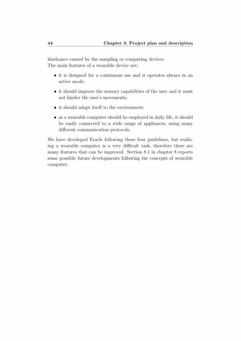
44 Chapter 3. Project plan and description
hindrance caused by the sampling or computing devices.
The main features of a wearable device are:
• it is designed for a continuous use and it operates always in an
active mode;
• it should improve the sensory capabilities of the user and it must
not hinder the user’s movements;
• it should adapt itself to the environment;
• as a wearable computer should be employed in daily life, it should
be easily connected to a wide range of appliances, using many
different communication protocols.
We have developed Eracle following these four guidelines, but realiz-
ing a wearable computer is a very difficult task, therefore there are
many features that can be improved. Section 8.1 in chapter 8 reports
some possible future developments following the concepts of wearable
computer.
3.3. General architecture of Eracle project 45
3.3 General architecture of Eracle project
The aim of Eracle project is to achieve a fully wearable system for
gesture recognition based on EMG analysis.
Figure 3.12 depicts the general architecture of the project. At the
beginning of the acquisition chain there is the user’s forearm, it means
that the first step consists in acquire the EMG signals generated by
the user’s movements. We have focused only on hand gestures, which
can be identified by the forearm muscles contraction; more details on
EMG signals can be found in appendix B.
The next step in the acquisition chain is the acquisition glove, that
can be easily worn by the user on the forearm. As depicted in fig-
ure 3.12, this device hosts two different modules:
• the sEMG electrodes employed for signal sampling;
• the EMG board that carries out some basic filtering on the raw
signal and converts it to digital values.
The last section is the biggest one: it provides the filtering of the EMG
signals and the recognition engine. It is fully implemented on Tegra
Devkit described in section 5.1 in chapter 5.
This last module is based on two executable files: EracleACQ and
EracleREC.
Both the applications provide the following units:
• a Serial Port Manager that handles the communication between
Devkit and EMG Board;
• the Parser module, that split the input data into three different
listings (one per channel) and removes some spurious data;
• the FastICA module that process and filter the raw input data;
• a RMS unit that computes the Root Mean Square value for each
channel.
The main difference between the two applications is in the last mod-
ule. In EracleACQ it is called NN Train, it trains the Neural Network
that will recognize the user’s movement; in EracleREC the last unit
is named NN Classify, as it handles the gesture recognition stage, em-
ploying the previously trained Neural Network.
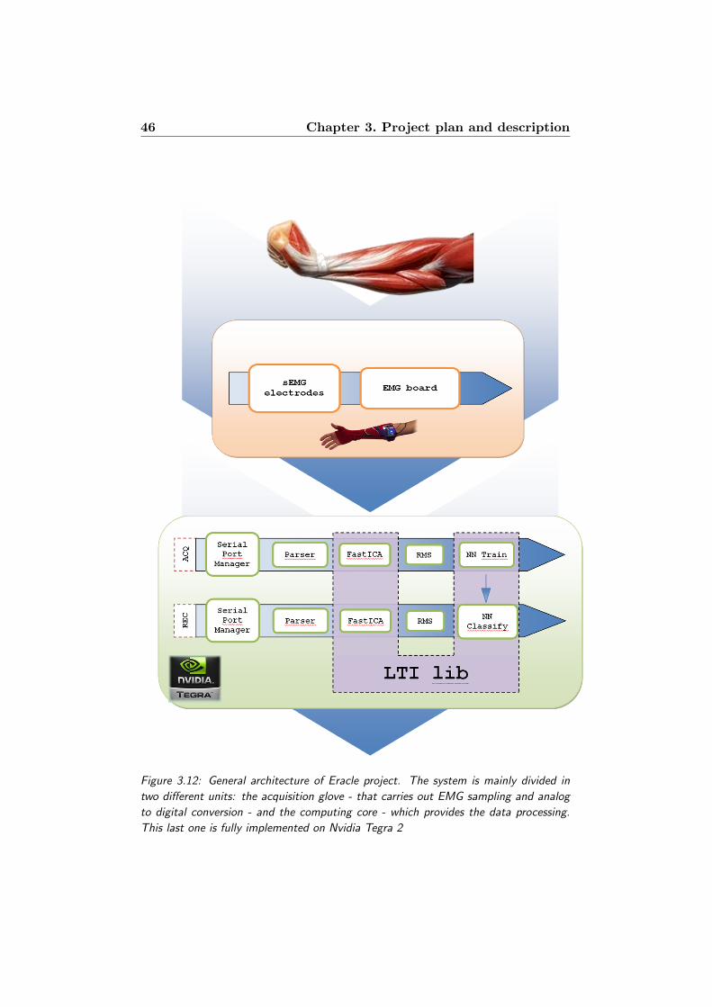
46 Chapter 3. Project plan and description
Figure 3.12: General architecture of Eracle project. The system is mainly divided in
two different units: the acquisition glove - that carries out EMG sampling and analog
to digital conversion - and the computing core - which provides the data processing.
This last one is fully implemented on Nvidia Tegra 2
3.3. General architecture of Eracle project 47
Another difference between the two executables is that in EracleACQ
the described modules are implemented on their own, while in Era-
cleREC the last four units are implemented in the same function. The
main reason of such choice is the computational performance: every
module of EracleACQ is fully independent by the others; it means that
it takes some files as input and generates some files as output, and
there is no cooperation between them. This choice entails that every
unit could run on his own. The main drawback is that the computa-
tional speed is reduced, mainly due to the big amount of I/O operations
performed. However, this is not a lack, as the data sampling for Neural
Network training is usually executed as batch process.
Instead, EracleREC directly interacts with the user, so its computa-
tional performance can’t be too low; moreover it handles just one single
movement (instead of EracleACQ, that processes about ten acquisi-
tions for each movement). For this reason the modules that perform
signal filtering and gesture recognition (Parser, FastICA, RMS and
NN Classify) are implemented together, avoiding the huge amount of
I/O operations performed by EracleACQ. This feature improves the
computational speed, but the system can’t be consider as a real time
application.
Chapter 8, section 8.1 presents some possible future developments to
improve the recognizer performance.
As shown in figure 3.12 the three modules FastICA, NN Train and NN
Classify are developed employing the features provided by LTIlib, a
mathematical library mainly used in image processing and computer
vision. The modules of Eracle project will be detailed described in
chapter 6.

48 Chapter 3. Project plan and description
Chapter 4
Independent Component
Analysis
“McCoy: In this galaxy, there’s a mathematical probability of three million
Earth-type planets. And in the entire universe, three million million galaxies
like this.
An in all of that, and perhaps more, only one of each of us. Don’t destroy
the one named Kirk.”
Balance of terror
Star Trek - The original series
This chapter provides both a basic introduction to Independent Com-
ponent Analysis (ICA) and some technical details about the application
of this method to biometric signals elaboration.
In the first section some mathematical and statistical properties of the
algorithm are discussed, focusing both on theoretical and implemen-
tations aspects. Finally, the last section provides some hints on how
this algorithm can be applied to EMG and EEG signals and introduces
some problems related with this choice.
4.1 Principles of ICA
Independent Component Analysis is a linear transformation method:
thus, it is an algorithm that represents multivariate data as a linear
transformation of the original statistical observations. ICA algorithms
search for the transformation that minimizes the statistical indepen-
dence of the original representation’s components, highlighting the es-
sential structure of the observed data.
50 Chapter 4. Independent Component Analysis
Considering a vector x of m observations, an unmixing matrix W and
a vector s of m sources ICA can be applied to x to obtain a linear
transform s = Wx maximizing a function F (s1...sn) that measures the
independence between the si components.
This definition could also be stated in a more practical way as:
Definition 4.1 (ICA). ICA of a random vector of statistical observa-
tion x of m components consists of estimating the following generative
model for the data:
x = As (4.1)
Where s is the vector of n sources that are assumed to be independent
and A is the constant mxn mixing matrix, which describes the linear
mix of the original signals.
Applying ICA requires that at least three main constraints have
been respected:
1. all the independent components si (except for maximum one com-
ponent) must be non-Gaussian;
2. the number of m observation of vector x must be at least as large
as the number of the independent sources n of vector s (m ≥ n);
3. the mixing matrix A must be of full column rank.
The first restriction is necessary as for Gaussian random variable un-
correlatedness implies independence. In fact statistical variables are
independent if the density function can be factorized:
f(y1, ..., yn) = f1(y1)f2(y2)...fn(yn) (4.2)
Instead, statistical variables are uncorrelated if:
E yiyj = E yiE yj (4.3)
Statistical independence is a much stronger requirement than uncorre-
latedness, but if the y1...yn statistical variables have a joint Gaussian
distribution, this two properties are equivalent. Thus any decorrelating
representation would give independent components searched by ICA.
Anyway, it is important to remark that even though some components
of source vector s are Gaussian it is still possible to identify the non-
Gaussian independent components.
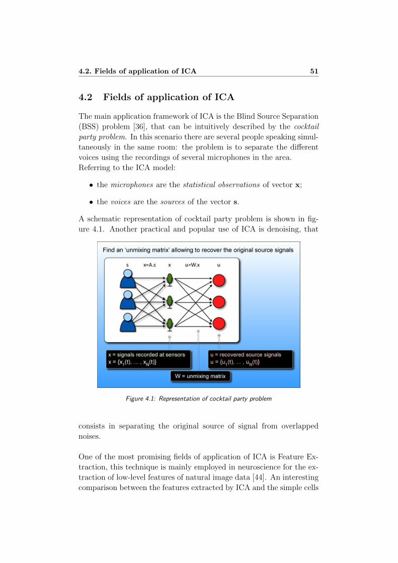
4.2. Fields of application of ICA 51
4.2 Fields of application of ICA
The main application framework of ICA is the Blind Source Separation
(BSS) problem [36], that can be intuitively described by the cocktail
party problem. In this scenario there are several people speaking simul-
taneously in the same room: the problem is to separate the different
voices using the recordings of several microphones in the area.
Referring to the ICA model:
• the microphones are the statistical observations of vector x;
• the voices are the sources of the vector s.
A schematic representation of cocktail party problem is shown in fig-
ure 4.1. Another practical and popular use of ICA is denoising, that
Figure 4.1: Representation of cocktail party problem
consists in separating the original source of signal from overlapped
noises.
One of the most promising fields of application of ICA is Feature Ex-
traction, this technique is mainly employed in neuroscience for the ex-
traction of low-level features of natural image data [44]. An interesting
comparison between the features extracted by ICA and the simple cells
52 Chapter 4. Independent Component Analysis
in primary visual cortex is reported in [50]. The authors also point out
that the best results are obtained using video sequences instead of still
images.
The quality of the results is similar to those obtained by Mallat with
wavelet in [39].

4.3. Estimating data model using ICA 53
4.3 Estimating data model using ICA
The estimation of a data model using ICA is performed in two different
steps: first, it is necessary to choose an objective (or contrast) function
to be minimized, then an algorithm for performing such minimization
must be selected.
The properties of ICA method are sensibly affected by these two choices,
in particular:
• the choice of the contrast function affected the statistical proper-
ties of the ICA method, such as robustness and variance;
• the choice of the algorithm affected properties such as convergence
speed, memory requirements and numerical stability.
4.3.1 Contrast functions
In addition to the statistical properties of ICA, the choice of contrast
function also affected the way of estimating the independent compo-
nents (ICs). There are two approaches: computing all the ICs at the
same time, or calculating only a single feature. In the second case the
procedure can be iterated to obtain several independent components.
Multi-unit contrast functions
For the first class of approach multi-unit functions are employed,
one of the most widely used is the log-likelihood function:
L =T∑t=1
m∑i=1
log fi(wTi x(t)) + T ln |detW | (4.4)
where W is the umixing matrix and x is the vector of statistical obser-
vations.
The main advantage of this approach is that (imposing some regularity
conditions) it is asymptotically efficient. The main drawback is that it
is necessary to know the probability densities of the independent com-
ponents and estimating them is a difficult task.
54 Chapter 4. Independent Component Analysis
Another widely used contrast function is the mutual information I
of the random vector of observation y1, ..., yn, that can be defined as:
I(y1, y2, ..., ym) =∑i
H(yi)−H(y) (4.5)
where H denotes the differential entropy of a vector of random statis-
tical variables:
H(y) = −∫f(y) log f(y)dy (4.6)
The mutual information is a measure of the dependence between vari-
ables: it is zero if and only if the variables are statistically independent,
so a way to estimate the ICA model consists in finding a transform that
minimizes this value.
The main drawback of mutual information is that it is difficult to esti-
mate, because to compute entropy it is necessary to assess the density
of the observations vector.
This problem can be solved using high-order cumulants, which are con-
stants that can be computed expanding as a Taylor series the log-
arithm of the characteristic function of a scalar random variable of
zero mean. The first three cumulants have a really simple expression:
k1 = E x = 0, k2 = E x2 and k3 = E x3. The most practical
and interesting cumulant is the fourth, called kurtosis:
k4 = Ex4− 3(E
x2
)2 (4.7)
This cumulant can be consider as a measure of the non-Gaussianity of
x, thus for a Gaussian random variable kurtosis is equal to zero.
Kurtosis is widely used in ICA methods, as it has these two properties:
kurt(x1 + x2) = kurt(x1) + kurt(x2) (4.8)
kurt(αx1) = α4kurt(x1) (4.9)
Using cumulants the mutual information can be (approximately) com-
puted as:
I(y) ≈ C +1
48
m∑i=1
[4k3(yi)2 + k4(yi)
2 + 7k4(yi)4 − 6k3(yi)
2k4(yi)]
(4.10)
where C is a constant and the observation yi must be uncorrelated.
However, this approximation holds only if the probability density of
observations is not far from Gaussian.
4.3. Estimating data model using ICA 55
One-unit contrast functions
Instead of estimating the whole ICA model it is possible to use one-
unit contrast functions, which compute only a single independent
component; iterating the procedure it is possible to estimate all the
ICs derived from the statistical observations.
Once the first independent component has been computed, it is pos-
sible to obtain the others maximizing the contrast function under the
constraints of decorrelation with respect to the ICs already found; this
incremental approach is called deflationary.
The main advantage of one-unit contrast functions is that the com-
putational complexity of ICA is noticeably reduced, especially if the
input data has a high dimension.
With these contrast functions the differential entropy defined in equa-
tion 4.6 can’t be applied, because that expression is not invariant from
scale transformations. Therefore a linearly invariant version of such
feature is computed: it is called negentropy, which means negative
normalized entropy. This value is always non-negative and it is zero if
and only if the statistical observations have a Gaussian distribution:
J(y) = H(ygauss)−H(y) (4.11)
where ygauss is a Gaussian random vector of the same covariance matrix
as y (which is the vector of statistical observations). Once negentropy
is defined, it is possible to determine the mutual information as defined
in equation 4.5:
I(y1, y2, ..., yn) = J(y)−∑i
J(yi) (4.12)
As discussed with respect to multi-unit contrast functions, it is possi-
ble to compute the ICs finding a representation in which mutual infor-
mation is minimized. Unfortunately - as in multi-unit case - mutual
information is difficult to estimate, so this feature can be approximated
by high-order cumulants (whit some additional difficulties with respect
to multi-unit contrast functions [32]).
Kurtosis approximation can be applied also with one-unit contrast
functions; in this case it is defined as:
kurt(wTx) = kurt(wTAs) = kurt(zT s) =m∑i=1
kurt(si) (4.13)
56 Chapter 4. Independent Component Analysis
where z = ATw.
Under the constraint ‖z‖2 = 1, it is possible to obtain the ICs maxi-
mizing the expression 4.13. However this solution is far from optimal
mainly for two reasons: first, because higher-order cumulants are sensi-
tive to outliers and secondly because this features are largely indepen-
dent by the structure in the middle of the distribution and are mostly
correlated to the tails of the statistical density.
For ICA another one-unit contrast function has been introduced in [32]
as a generalization of kurtosis that tries to combine some features such
as:
• no prior knowledge of the densities of the ICs;
• simplicity of algorithmic implementation;
• interesting statistical properties.
This objective function is called generalized contrast function and it
practically a measure of non-normality; it can be constructed using
any functions G and considering the difference of the expectation of G
for the actual data and the expectation of G for Gaussian data.
4.3.2 Algorithms for ICA
Once a contrast function has been defined, it is necessary to select a
way to optimize it, choosing an appropriate algorithm.
Some preprocessing is usually applied before computing the ICs with
the selected algorithm, mainly it consists in sphering the input data. It
means that the observed variable x of the classical ICA model x = As
is transformed to a variable v
v = Qx (4.14)
such that the covariance matrix of v is equal to unity (EvvT
= I).
This transformation is always possible and - even in cases in which it is
not strictly necessary - improves the convergence speed of the selected
algorithm.
The variable v can be defined as (from 4.1 and 4.14):
v = Bs (4.15)
where B = QA is an orthogonal matrix, because:
EvvT
= BEssTBT = BBT = I (4.16)

4.3. Estimating data model using ICA 57
remembering that a square real matrix B is orthogonal if BTB =
BBT = I.
The main advantage of preprocessing is that the problem of finding an
arbitrary matrix A defined in 4.1 has been reduced to the simpler prob-
lem of finding an orthogonal matrix B, which can be used to obtain
the ICs simply by transposing it:
s = BTv (4.17)
instead of computational-expensive inversion of matrix A.
The first ICA algorithm was introduced by Jutten and Herault in [36]
and it is inspired by neural networks. The matrix of weights is updated
according to the rule:
∆Wij ∝ g1(yi)g2(yj) (4.18)
for elements outside the diagonal (thus when i 6= j) and it is zero for
the diagonal terms. The two relations g1 and g2 are odd non-linear
functions. The output terms yi are computed at every iteration as:
(I +W )−1x (4.19)
The two main drawbacks of this algorithm are that it converges only
under severe restrictions, and it is computationally expensive (mainly
due to the matrix inversion computed at every iteration).
These two disadvantages can be (partially) resolved using non-linear
decorrelation algorithms such as EASI, introduced in [27] which pro-
poses the following learning rule, that avoids the matrix inversion op-
eration:
∆W ∝ (I − yyT − g(y)yT + yg(yT ))W (4.20)
Another interesting class of algorithms is based on maximization of net-
work entropy (infomax), it is similar to maximum likelihood approach.
They are mainly based on (stochastic) gradient ascent for objective
function. The main drawback of this class of algorithms is that they
converge very slowly, but speed can be improved by preprocessing data
with whitening.
One of the most practical and widely used algorithms for Independent
Component Analysis is FastICA. It is a fixed-point algorithm originally
58 Chapter 4. Independent Component Analysis
proposed in 1997 by Hyvarinen and Oja [32].
It requires sphering preprocessing and the learning rule can be imple-
mented as:
w(k) = Exg(w(k − 1)Tx)
− E
g′(w(k − 1)Tx
w(k − 1) (4.21)
The non linear function g is the derivative of the function G defined in
general contrast function introduced in [32].
Several systems can estimate the ICs using deflationary (see 4.3.1) or
symmetric method: in this last configuration the ICs are all estimated
in parallel.
The convergence speed of the algorithm is high, as FastICA uses sample
averages computed over larger amount of data, instead of using every
data point immediately for learning. An interesting property is that
symmetric FastICA is essentially equivalent to a Newton method for
maximum likelihood estimation, that makes this method suitable both
for one-unit and multi-unit contrast functions.
4.4. ICA for biometric analysis 59
4.4 ICA for biometric analysis
In biometrics analysis ICA methods are mainly employed for denois-
ing. The main problem in using ICA methods with noisy signals is
the lack of robustness of the algorithms, however - for EMG data anal-
ysis - these approaches have been used with good results by Naik et
al. ( [43], [42] and [41]). The main difficulty of EMG signals is that
they have a probability density close to Gaussian, while noises (such as
motion artifacts) have non-Gaussian distribution (as discussed in sec-
tion 4.1, ICA methods cannot deal with purely Gaussian distribution,
because in this case uncorrelatedness entails statistical independence).
It is important to underline that EMG signals have probability density
that is only close to Gaussian, so ICA methods can be successfully
employed in some denoising application using a Gaussianity-based con-
trast function, such as:
G(x) = − 1
αexp (−α
2x2) (4.22)
Moreover, EMG analysis for gesture recognition can be considered as
practical implementation of BSS problem (see section 4.2) where:
• the sources are the signals produced by the muscles (with refer-
ence to the cocktail party problem they are the people’s voices);
• the statistical observations are the data acquired with the elec-
trodes (with reference to the cocktail party problem they are the
microphones).
From this point of view, ICA is also used to reduce the cross-talking
between two or more muscles that are activated in the same contraction,
thus the obtained ICs are the real signals generated by each motor unit.
These two considerations are also supported by [43].
Figures 4.2 and 4.3 depict an example of ICA application in biometric
signal analysis.
Figure 4.2 shows the input source data corresponding to a wrist
extension; note that the y-axis values are the same for all the three
graphs. Figure 4.3 shows the same signals processed by FastICA algo-
rithm. First of all the amplitude values of the three signals have been
normalized. Moreover the signal sampled on channel 2 - that is very
noisy, maybe due to crosstalking - has been limited by ICA algorithm.
On the contrary, source signal sampled by channel 1 has been boosted,
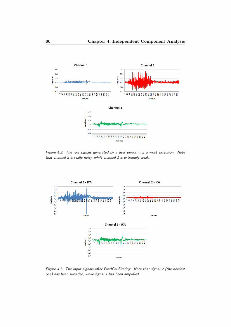
60 Chapter 4. Independent Component Analysis
Figure 4.2: The raw signals generated by a user performing a wrist extension. Note
that channel 2 is really noisy, while channel 1 is extremely weak.
Figure 4.3: The input signals after FastICA filtering. Note that signal 2 (the noisiest
one) has been subsided, while signal 1 has been amplified.

4.4. ICA for biometric analysis 61
while the input signal on channel 3 remained virtually unchanged. Fig-
ure 4.4 depicts all the three signals before and after the application of
the ICA algorithm. Removing the noise from the signals it is possi-
ble to correctly extract some features (like the RMS) that identify the
gesture performed by the user.
(a)
(b)
Figure 4.4: The three input files before (a) and after (b) the FastICA filtering. Note
the amplitude difference of signal 2 and 1.
62 Chapter 4. Independent Component Analysis
There are also other drawbacks in employing ICA for EMG analysis:
first of all, the exact amplitude and sign of independent components
can’t be determined and, secondly, the order of the ICs cannot be deter-
mined. Moreover, ICA employing high-order statistics (like kurtosis)
aren’t performing well on EMG analysis. Maybe this lack of perfor-
mance is due to the need of a larger dataset, that isn’t usually available
in HCI application base on EMG analysis. This consideration is also
supported by [42], in which a second order statistic-based algorithm
(TDSEP) gives an overall efficiency of 97% in hand gesture recognition.
ICA methods have also been applied in electroencephalography for
separating the EEG from artifacts (for more information about EEG
see 2.1.2). As described in [51] the application of such method leads to
some interesting and promising results in EEG analysis, however the
task of canceling artifacts from EEG signals remains a central problem
in electroencephalography data analysis.
Chapter 5
Hardware devices
“Spock: I saw VGer’s planet. A planet populated by living machines. Unbe-
liavable technology. V’Ger has knowledge that spans this universe. And yet,
with all its pure logic... V’Ger is barren. Cold. No mystery. No beauty. I
should have... known...
Kirk: known? known what? what should you have known?
Spock: (Holding Kirk’s hand) this simple feeling ... is beyond VGer’s com-
prehension. No meaning. No hope. No answers. It’s asking questions: Is
this... all that I am? Is there nothing more?”
Star Trek - The motion picture
This chapter provides a description of the devices employed in Eracle
project.
The first section is focused on Nvidia Tegra 2, the CPU that carries out
all the signal processing and recognition procedures. The EMG board
employed for electromyogram signals acquisition and digital conver-
sion is presented in section two. The last paragraph presents a brief
description of the FTDI serial driver, which has been employed to con-
nect sEMG board to Tegra.
5.1 Nvidia Tegra 2
Nvidia Tegra 2 is the core of Eracle wearable system; it is a system-on-
Chip (SoC) mobile processor, specifically designed for high performance
computing on smart devices like tablets, smartphones and mini-laptop.
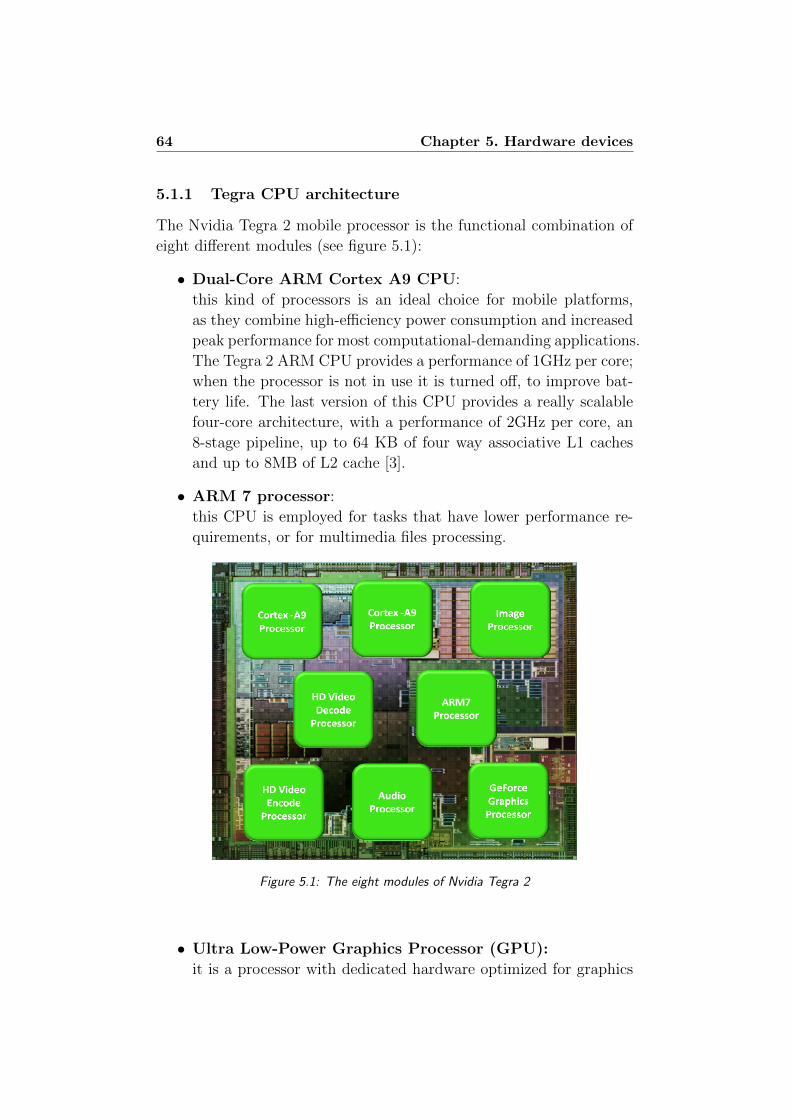
64 Chapter 5. Hardware devices
5.1.1 Tegra CPU architecture
The Nvidia Tegra 2 mobile processor is the functional combination of
eight different modules (see figure 5.1):
• Dual-Core ARM Cortex A9 CPU:
this kind of processors is an ideal choice for mobile platforms,
as they combine high-efficiency power consumption and increased
peak performance for most computational-demanding applications.
The Tegra 2 ARM CPU provides a performance of 1GHz per core;
when the processor is not in use it is turned off, to improve bat-
tery life. The last version of this CPU provides a really scalable
four-core architecture, with a performance of 2GHz per core, an
8-stage pipeline, up to 64 KB of four way associative L1 caches
and up to 8MB of L2 cache [3].
• ARM 7 processor:
this CPU is employed for tasks that have lower performance re-
quirements, or for multimedia files processing.
Figure 5.1: The eight modules of Nvidia Tegra 2
• Ultra Low-Power Graphics Processor (GPU):
it is a processor with dedicated hardware optimized for graphics
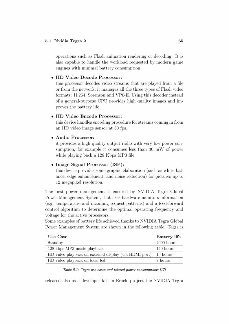
5.1. Nvidia Tegra 2 65
operations such as Flash animation rendering or decoding. It is
also capable to handle the workload requested by modern game
engines with minimal battery consumption.
• HD Video Decode Processor:
this processor decodes video streams that are played from a file
or from the network; it manages all the three types of Flash video
formats: H.264, Sorenson and VP6-E. Using this decoder instead
of a general-purpose CPU provides high quality images and im-
proves the battery life.
• HD Video Encode Processor:
this device handles encoding procedure for streams coming in from
an HD video image sensor at 30 fps.
• Audio Processor:
it provides a high quality output radio with very low power con-
sumption, for example it consumes less than 30 mW of power
while playing back a 128 Kbps MP3 file.
• Image Signal Processor (ISP):
this device provides some graphic elaboration (such as white bal-
ance, edge enhancement, and noise reduction) for pictures up to
12 megapixel resolution.
The best power management is ensured by NVIDIA Tegra Global
Power Management System, that uses hardware monitors information
(e.g. temperature and incoming request patterns) and a feed-forward
control algorithm to determine the optimal operating frequency and
voltage for the active processors.
Some examples of battery life achieved thanks to NVIDIA Tegra Global
Power Management System are shown in the following table: Tegra is
Use Case Battery life
Standby 2000 hours
128 kbps MP3 music playback 140 hours
HD video playback on external display (via HDMI port) 16 hours
HD video playback on local lcd 8 hours
Table 5.1: Tegra use-cases and related power consumptions [17]
released also as a developer kit; in Eracle project the NVIDIA Tegra
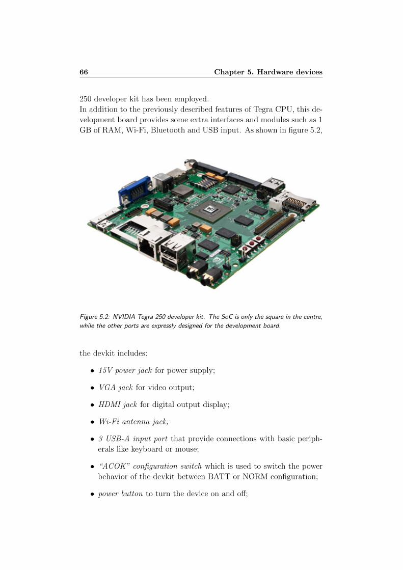
66 Chapter 5. Hardware devices
250 developer kit has been employed.
In addition to the previously described features of Tegra CPU, this de-
velopment board provides some extra interfaces and modules such as 1
GB of RAM, Wi-Fi, Bluetooth and USB input. As shown in figure 5.2,
Figure 5.2: NVIDIA Tegra 250 developer kit. The SoC is only the square in the centre,
while the other ports are expressly designed for the development board.
the devkit includes:
• 15V power jack for power supply;
• VGA jack for video output;
• HDMI jack for digital output display;
• Wi-Fi antenna jack;
• 3 USB-A input port that provide connections with basic periph-
erals like keyboard or mouse;
• “ACOK” configuration switch which is used to switch the power
behavior of the devkit between BATT or NORM configuration;
• power button to turn the device on and off;
5.1. Nvidia Tegra 2 67
• recovery button that places the devkit in recovery mode; it is a
special configuration in which the device is ready to receive a new
OS image;
• reset button for soft reset of the board;
• microphone and headphone jack for sound output;
• Ethernet jack;
• SD slot card;
• USB-mini jack to connect the devkit to the host pc.
5.1.2 Developing software on Tegra
The previously described devkit is a completely novelty in the field
of embedded CPU, mainly because it combines the reduced size (that
makes it suitable for wearable applications) and the high computing
performance.
This processor is not available for purchase on Italian market, it has
been provided to some technological partners of Nvidia Corporation.
One of these partner is Seco s.r.l.([19]), that provides the devkit em-
ployed to develop Eracle project.
The reduced spread of this kind of platform makes it suitable for the
development of a completely new project. However, building a com-
pletely new application starting from scratch is a difficult task, mainly
due to the lack of supports and information regarding this processor.
Another difficulty is the lack of libraries and code available for this
kind of architecture. This leads to two possible choices: the first is the
development of a completely new library optimized for the ARM archi-
tecture and the second consist in “fitting” a library already available
for x86 architecture. For the development of Eracle project we have
chosen the last solution, as the aim of this project is not to build a
basic library for ARM processors, but to realize a gesture recognition
system. Some details among the adaptation of a mathematical library
for ARM architecture are discussed in section 6.1.
To use the devkit it is necessary to install an appropriate OS on the
board, this operation is usually called “flashing”.
There are mainly two operative systems that can be flashed on the de-
vkit: windows CE or Android (see section 2.2.2 for more information

68 Chapter 5. Hardware devices
concerning these OS). The appropriate msi file (it depends on the OS
of the host PC) can be downloaded from the provided page on Tegra
developer site [16], where it is also possible to retrieve some useful tools
and demos. It is important to point out that almost all the provided
support and examples are referred to Android.
Once the installation procedure is complete, a fully functional OS is
available on the devkit; this feature makes the application development
easier than in devices like PIC and DsPIC.
Once the OS has been installed it is possible to develop software appli-
cations directly on the host pc and deploy them directly to the devkit.
For Windows CE the best choice is to develop a smart device appli-
cation using Microsoft Visual Studio; to realize software that runs on
Tegra, it is necessary to install the Standard Software Development Kit
(STANDARDSDK 500) for Windows CE on the host pc. This package
provides support for ARM4 and other mobile processors.
Tegra development board supports only a subset of .Net Framework,
called .Net Compact Framework; it is a mobile-oriented environment
mainly designed for mobile devices such as PDA, pocket PC, mobile
phones and embedded processors. .Net Compact Framework offers
these main functionalities:
• it provides an abstraction layer for executable files, making the
executable code independent of the specific hardware platform;
• it supports the most common network protocols and offers facili-
ties for handling connections with XML Web services;
• it provides a template for code development that is specific for
smart device applications;
• it offers some optimizations related to the limited resources of the
mobile systems.
The main advantage in developing an application on the devkit is that
it is simply created as a Windows program. It means that the program-
mer doesn’t care about the specific underlying hardware platform, but
he can write his code in pure C++ using all the structure provided by
this programming language.
Moreover, the Visual Studio Wizard already provides the main func-
tions and classes required for a Windows application (such as the Win-
Main and WndProc functions, that handle the main message loop).
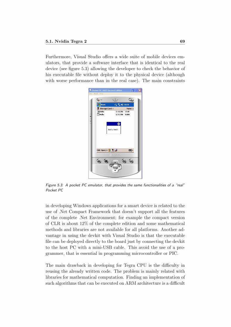
5.1. Nvidia Tegra 2 69
Furthermore, Visual Studio offers a wide suite of mobile devices em-
ulators, that provide a software interface that is identical to the real
device (see figure 5.3) allowing the developer to check the behavior of
his executable file without deploy it to the physical device (although
with worse performance than in the real case). The main constraints
Figure 5.3: A pocket PC emulator, that provides the same functionalities of a “real”
Pocket PC
in developing Windows applications for a smart device is related to the
use of .Net Compact Framework that doesn’t support all the features
of the complete .Net Environment; for example the compact version
of CLR is about 12% of the complete edition and some mathematical
methods and libraries are not available for all platforms. Another ad-
vantage in using the devkit with Visual Studio is that the executable
file can be deployed directly to the board just by connecting the devkit
to the host PC with a mini-USB cable. This avoid the use of a pro-
grammer, that is essential in programming microcontroller or PIC.
The main drawback in developing for Tegra CPU is the difficulty in
reusing the already written code. The problem is mainly related with
libraries for mathematical computation. Finding an implementation of
such algorithms that can be executed on ARM architecture is a difficult
70 Chapter 5. Hardware devices
task.
One clear example of this problem is the Boost library ([6]), which is
one of the best choices for mathematical computation algorithms: even
if it is fully written in C++, it is unavailable for ARM architecture.
This is also the case with IT++ ([12]), an open source mathematical
library that implements useful structure such as matrices, vectors and
algorithms for signal processing (including FastICA).
Unfortunately these libraries are expressly developed for x86 architec-
ture, thus, for using them on an ARM machine it is necessary to port
or recompile them. Modifying such amount of code in order to make
it executable on a system which is different from the original one is
an arduous task. This difficulty is mainly due to the complexity and
the dimension of such libraries, but also to the limitations in using the
.Net Compact Framework instead of the complete version of this envi-
ronment.
Moreover, even if these libraries are successfully compiled for ARM ar-
chitecture, they performed badly with respect to their version for the
original target machine. In some cases it is also necessary to remove
some features that are incompatible with the ARM architecture or the
.Net Compact Framework, with a lack of functionalities with respect
to the original version of the library.
For more information about porting library on ARM architecture, see
chapter 6, section 6.1.
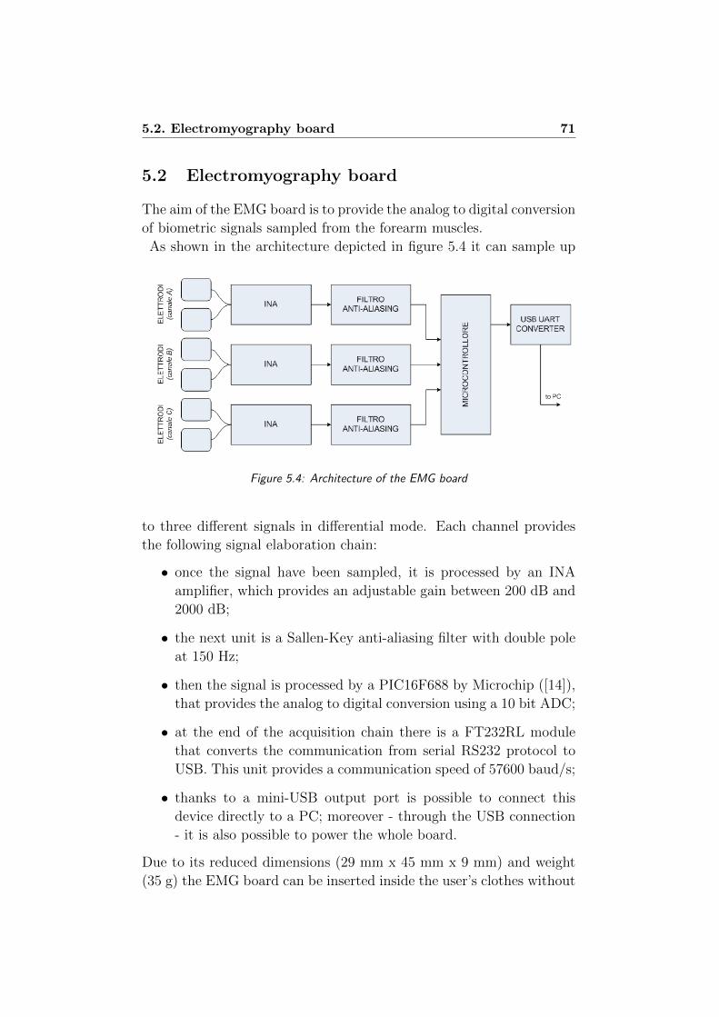
5.2. Electromyography board 71
5.2 Electromyography board
The aim of the EMG board is to provide the analog to digital conversion
of biometric signals sampled from the forearm muscles.
As shown in the architecture depicted in figure 5.4 it can sample up
Figure 5.4: Architecture of the EMG board
to three different signals in differential mode. Each channel provides
the following signal elaboration chain:
• once the signal have been sampled, it is processed by an INA
amplifier, which provides an adjustable gain between 200 dB and
2000 dB;
• the next unit is a Sallen-Key anti-aliasing filter with double pole
at 150 Hz;
• then the signal is processed by a PIC16F688 by Microchip ([14]),
that provides the analog to digital conversion using a 10 bit ADC;
• at the end of the acquisition chain there is a FT232RL module
that converts the communication from serial RS232 protocol to
USB. This unit provides a communication speed of 57600 baud/s;
• thanks to a mini-USB output port is possible to connect this
device directly to a PC; moreover - through the USB connection
- it is also possible to power the whole board.
Due to its reduced dimensions (29 mm x 45 mm x 9 mm) and weight
(35 g) the EMG board can be inserted inside the user’s clothes without
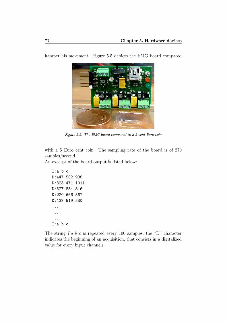
72 Chapter 5. Hardware devices
hamper his movement. Figure 5.5 depicts the EMG board compared
Figure 5.5: The EMG board compared to a 5 cent Euro coin
with a 5 Euro cent coin. The sampling rate of the board is of 270
samples/second.
An excerpt of the board output is listed below:
I:a b c
D:447 502 988
D:323 471 1011
D:327 834 816
D:220 666 567
D:438 519 530
...
...
...
I:a b c
The string I:a b c is repeated every 100 samples; the “D” character
indicates the beginning of an acquisition, that consists in a digitalized
value for every input channels.
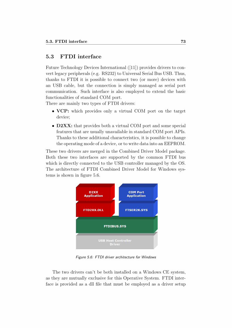
5.3. FTDI interface 73
5.3 FTDI interface
Future Technology Devices International ([11]) provides drivers to con-
vert legacy peripherals (e.g. RS232) to Universal Serial Bus USB. Thus,
thanks to FTDI it is possible to connect two (or more) devices with
an USB cable, but the connection is simply managed as serial port
communication. Such interface is also employed to extend the basic
functionalities of standard COM port.
There are mainly two types of FTDI drivers:
• VCP: which provides only a virtual COM port on the target
device;
• D2XX: that provides both a virtual COM port and some special
features that are usually unavailable in standard COM port APIs.
Thanks to these additional characteristics, it is possible to change
the operating mode of a device, or to write data into an EEPROM.
These two drivers are merged in the Combined Driver Model package.
Both these two interfaces are supported by the common FTDI bus
which is directly connected to the USB controller managed by the OS.
The architecture of FTDI Combined Driver Model for Windows sys-
tems is shown in figure 5.6.
Figure 5.6: FTDI driver architecture for Windows
The two drivers can’t be both installed on a Windows CE system,
as they are mutually exclusive for this Operative System. FTDI inter-
face is provided as a dll file that must be employed as a driver setup

74 Chapter 5. Hardware devices
file on the host pc when the external device is plugged.
In Eracle project, the VCP version of FTDI drivers has been employed,
as we just need basic IO operations on a virtual serial port. This kind
of interface makes possible to exchange data between the EMG board
(described in section 5.2) and the devkit (described in section 5.1).
The EMG board can be connected with a USB-mini cable to the de-
vkit, which retrieves the sampled data simple by opening a serial port
as a file and reading the signal’s digital values from it. In our case,
the virtual serial port created by the FTDI interface is named COM10;
this information can be retrieved by using the Remote Registry Editor
available on the host PC.
The following code listing shows the main steps necessary to handle
the serial connection and to retrieve the data acquired by the EMG
board.
/*main variables for the serial port handling*/
HANDLE hSer;
DCB dcb;
dcb.DCBlength=sizeof(dcb);
dcb.BaudRate =57600;
/*variables for serial port reading*/
INT rc;
CHAR buffer [15000];
DWORD bytesRead;
/*create a serial port handler*/
hSer=CreateFile(TEXT("$device \\ COM10"),
GENERIC_READ|GENERIC_WRITE ,0,
NULL ,OPEN_EXISTING ,0,NULL);
/*set the COM port options*/
GetCommState(hSer ,&dcb);
SetCommState(hSer ,&dcb);
PurgeComm(hSer ,PURGE_TXABORT | PURGE_RXABORT
| PURGE_TXCLEAR | PURGE_RXCLEAR );
5.3. FTDI interface 75
/*read data from the COM port
and put them into the buffer*/
rc = ReadFile(hSer ,buffer ,
sizeof(buffer),&bytesRead ,0)
/*close the virtual serial port connection*/
CloseHandle(hSer);

76 Chapter 5. Hardware devices
Chapter 6
Project development
“ We are the Borg. You will be assimilated. Your biological and technological
distinctiveness will be added to our own. Resistance is futile.”
Star Trek VIII - First Contact
This chapter provides a detailed description of Eracle project.
As previously described in chapter 3, section 3.3, Eracle project consists
of two different modules.
The first one is implemented on the Acquisition Glove that samples the
EMG signals and converts them to digital values. The main sub-units
of this module are:
• the sEMG electrodes that acquire the input signal from the
user’s skin;
• the EMG Board that converts the input EMG signals to digital
values.
Section 6.2, provides some details about the Acquisition Glove.
The second module is fully developed on Tegra Devkit, it provides the
data processing for the acquired signals and the gesture recognition
engine. It consists of two different executable files: EracleACQ, that
provides the training stage for the classifier, and EracleREC that iden-
tifies the gesture performed by the user. The sub-units of this module
are:
• a Serial Port Manager that handles the communication be-
tween Devkit and EMG Board;
78 Chapter 6. Project development
• the Parser unit, that split the input data into three different
listings (one per channel) and erases the spurious data;
• the FastICA unit that processes and filters the raw input data;
• a RMS unit that computes the Root Mean Square value for each
channel;
• the NN Train module that trains the Multi Layer Perceptron
that will recognize the user’s gestures;
• the NN Classify unit, that classifies the user’s gesture employing
the previously trained Neural Network.
The last unit is implemented only in EracleREC, while the NN train
module is developed only on EracleACQ. Section 6.3, provides some
details about all the modules implemented on the Devkit.
Both the FastICA module and the Neural Network units are developed
using some features of LTIlib, a C++ library mainly employed for
image processing. The first section of this chapter provides some details
about LTIlib and how it has been recompiled for ARM architecture.
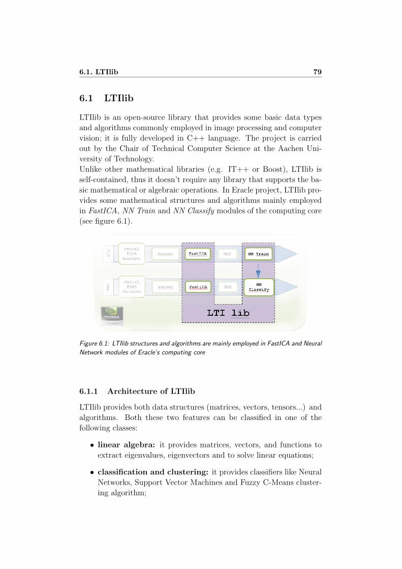
6.1. LTIlib 79
6.1 LTIlib
LTIlib is an open-source library that provides some basic data types
and algorithms commonly employed in image processing and computer
vision; it is fully developed in C++ language. The project is carried
out by the Chair of Technical Computer Science at the Aachen Uni-
versity of Technology.
Unlike other mathematical libraries (e.g. IT++ or Boost), LTIlib is
self-contained, thus it doesn’t require any library that supports the ba-
sic mathematical or algebraic operations. In Eracle project, LTIlib pro-
vides some mathematical structures and algorithms mainly employed
in FastICA, NN Train and NN Classify modules of the computing core
(see figure 6.1).
Figure 6.1: LTIlib structures and algorithms are mainly employed in FastICA and Neural
Network modules of Eracle’s computing core
6.1.1 Architecture of LTIlib
LTIlib provides both data structures (matrices, vectors, tensors...) and
algorithms. Both these two features can be classified in one of the
following classes:
• linear algebra: it provides matrices, vectors, and functions to
extract eigenvalues, eigenvectors and to solve linear equations;
• classification and clustering: it provides classifiers like Neural
Networks, Support Vector Machines and Fuzzy C-Means cluster-
ing algorithm;
80 Chapter 6. Project development
• Image processing: this class provides wavelets, linear filters and
other algorithms that deal with image processing problems;
• Visualization and drawing tools: these classes provide the
viewer objects to display or manipulate an image.
The architecture of LTI library is really simple and it is based on three
main entities: functors, parameters and states.
• Functors
Functors are classes containing all the functions of an algorithm.
Every functor class contains at least one apply method that exe-
cutes the algorithm on the source data provided .
Consider a Multi Layer Perceptron Neural Network as an exam-
ple: the object that represents the classifier is a functor.
• Parameters
One instance of this class is encapsulated in every functor, as it
provides the specifications of the algorithm. The user can set this
values by using the setParameters method related to the functor
class. It is also possible to employ the default parameter class
initialized when the functor class is declared.
Examples of parameters in a Neural Network are: the number of
epochs, the number of neurons in the hidden layer and the value
of the learning rate.
• States
States are attributes that are computed during the algorithm’s
execution, but that aren’t required by the user.
Considering the NN example, a state is the number of weights
computed during the training stage, that isn’t explicitly defined
by the user but is computed by the training algorithm.
The main advantages in using these three different entities are: first
of all the behavior of the algorithm is independent of its parameters,
thus the functor is completely uncorrelated from the input data and
it implements only the functionality of the procedure; secondly this
is a general interface that can be applied to every algorithm, simply
overloading the apply methods that executes the algorithm.
Figure 6.2 depicts the general architecture of LTIlib.

6.1. LTIlib 81
Figure 6.2: General architecture of an LTILIB class: the functor is the general structure
that contains both the algorithm and its options. The user sets the desired configuration
with parameters. States and Parameters implement the desired functionality of the
algorithm.
6.1.2 Recompiling LTIlib
One of the main disadvantages in using the Devkit described in chap-
ter 5 is the lack of libraries available for ARM architecture. Thus, a
developer has two possible choices: he could write from scratch the
functions and the structures he needs, or he could try to recompile an
existing library.
In Eracle project we mainly need structures, like matrices and vectors,
algorithms, like FastICA and classifiers, like Multi Layer Perceptrons.
As these features are already available in some open-source libraries
and there are some difficulties in writing them from scratch, we’ve de-
cided to convert an existing library to ARM architecture.
We have identified three libraries that could be suitable for our pur-
pose: Boost, IT++ and LTIlib. We have failed in recompiling Boost
and IT++, mainly because they are not self-contained, but they are
based on other libraries that provide optimized computing algorithms.
For example, IT++ libraries are more powerful than LTIlib, as they
manage matrices and vectors in a simpler way, moreover they offer
a wide selection of algorithms; unfortunately, IT++ libraries require
BLAS and LAPACK to handle basic mathematical and algebraic struc-
tures with the related operations. Recompile three libraries for ARM
architecture is a more difficult task than recompile only one.
82 Chapter 6. Project development
LTIlib provides less powerful features and less optimizations than IT++
or Boost, but it is self-contained and more easy-to-handle, as it is writ-
ten in “pure” C++ code. Thanks to these features it has been success-
fully recompiled for ARM architecture.
To recompile LTIlib for ARM architecture we have adopted two main
approaches:
• if the problematic feature is related to visualization, or to some
algorithms that are useless for our project, the corresponding code
is simply commented;
• in the other cases, the problematic code has been rewritten or
adapted.
Not all the features have been retained. First of all it has been neces-
sary to remove all the references to GTK libraries that are employed
for image visualization. To achieve this result, some preprocessor di-
rectives that configure GTK as standard visualization tool have been
deleted.
Another change is related to optimized assembly operations. It is a
common case that mathematical libraries implement some functions
directly in assembly: unfortunately, x86 assembler (the target CPU
of LTIlib) is different from ARM assembler. To avoid this problem,
the assembly functions have been replaced with less optimized C++
instructions.
Some preprocessor directives have been modified to be executed on
Windows CE, which is not the target OS of LTIlib.
Other changes involve the header files provided with STANDARD-
SDK 500. Some of these files don’t contain all the elements and decla-
rations required by LTIlib. For example, the header file stat.h provided
with STANDARDSDK 500, requires some additional definitions such
as:
typedef unsigned int _dev_t;
typedef unsigned short _ino_t;
typedef long _off_t;
It is important that the include paths are set in an appropriate way:
they must be referred to the include files specifically provided for Win-
dows CE and to the STANDARDSDK 500 path.
6.1. LTIlib 83
Some changes consist in pure casting operations, such as the following
one, in which the file name has been converted to LPCTSTR type:
//before...
if(! DeleteFile(fileName ))
//... and after
if(! DeleteFile (( LPCTSTR)fileName ))
Another important change regards threads and the process manage-
ment routines implemented in LTIlib. These two features provide func-
tions like fork and exec employed in UNIX environment, but they lead
to compilation error, so these feature has been removed.
At the end of this procedure a static library has been achieved, that
can easily be linked at compile time with the source code developed in
C++. Some modifications has been also necessary in Visual Studio,
such as enables the Run Time Type Information (RTTI) option.
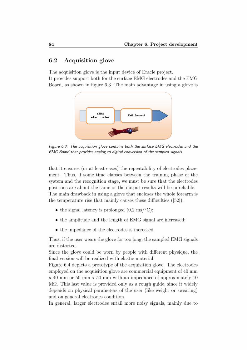
84 Chapter 6. Project development
6.2 Acquisition glove
The acquisition glove is the input device of Eracle project.
It provides support both for the surface EMG electrodes and the EMG
Board, as shown in figure 6.3. The main advantage in using a glove is
Figure 6.3: The acquisition glove contains both the surface EMG electrodes and the
EMG Board that provides analog to digital conversion of the sampled signals.
that it ensures (or at least eases) the repeatability of electrodes place-
ment. Thus, if some time elapses between the training phase of the
system and the recognition stage, we must be sure that the electrodes
positions are about the same or the output results will be unreliable.
The main drawback in using a glove that encloses the whole forearm is
the temperature rise that mainly causes these difficulties ([52]):
• the signal latency is prolonged (0,2 ms/C);
• the amplitude and the length of EMG signal are increased;
• the impedance of the electrodes is increased.
Thus, if the user wears the glove for too long, the sampled EMG signals
are distorted.
Since the glove could be worn by people with different physique, the
final version will be realized with elastic material.
Figure 6.4 depicts a prototype of the acquisition glove. The electrodes
employed on the acquisition glove are commercial equipment of 40 mm
x 40 mm or 50 mm x 50 mm with an impedance of approximately 10
MΩ. This last value is provided only as a rough guide, since it widely
depends on physical parameters of the user (like weight or sweating)
and on general electrodes condition.
In general, larger electrodes entail more noisy signals, mainly due to
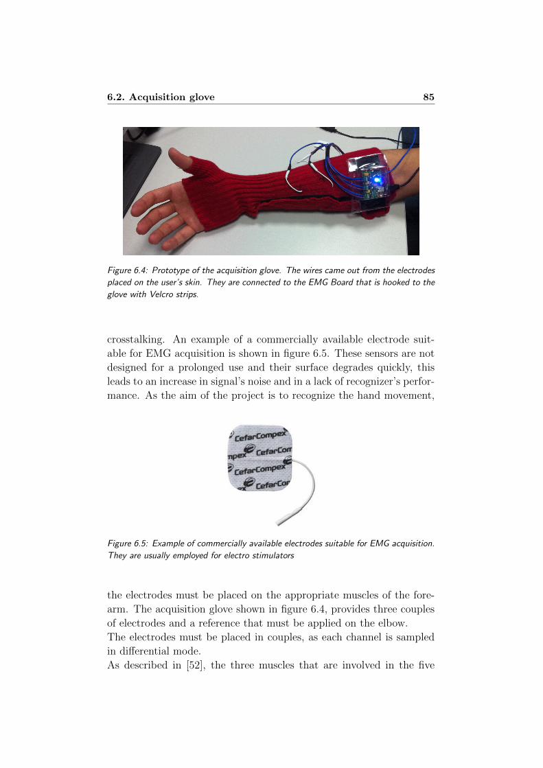
6.2. Acquisition glove 85
Figure 6.4: Prototype of the acquisition glove. The wires came out from the electrodes
placed on the user’s skin. They are connected to the EMG Board that is hooked to the
glove with Velcro strips.
crosstalking. An example of a commercially available electrode suit-
able for EMG acquisition is shown in figure 6.5. These sensors are not
designed for a prolonged use and their surface degrades quickly, this
leads to an increase in signal’s noise and in a lack of recognizer’s perfor-
mance. As the aim of the project is to recognize the hand movement,
Figure 6.5: Example of commercially available electrodes suitable for EMG acquisition.
They are usually employed for electro stimulators
the electrodes must be placed on the appropriate muscles of the fore-
arm. The acquisition glove shown in figure 6.4, provides three couples
of electrodes and a reference that must be applied on the elbow.
The electrodes must be placed in couples, as each channel is sampled
in differential mode.
As described in [52], the three muscles that are involved in the five
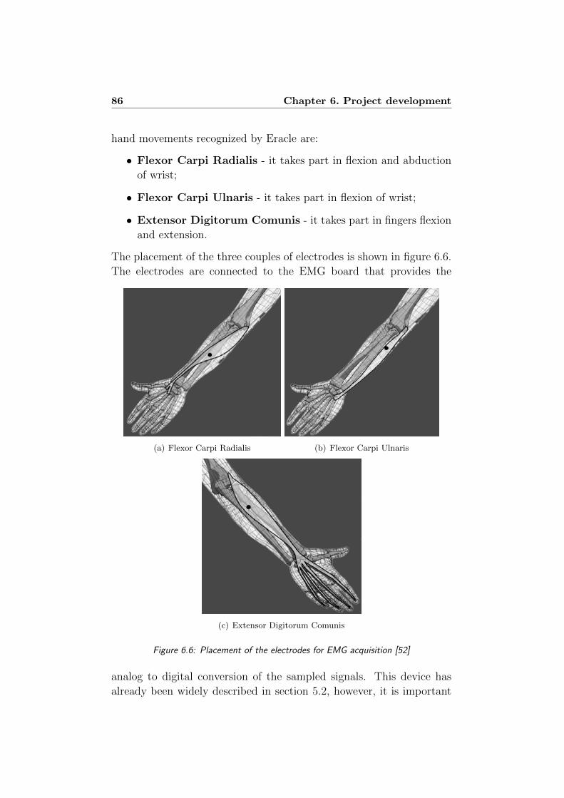
86 Chapter 6. Project development
hand movements recognized by Eracle are:
• Flexor Carpi Radialis - it takes part in flexion and abduction
of wrist;
• Flexor Carpi Ulnaris - it takes part in flexion of wrist;
• Extensor Digitorum Comunis - it takes part in fingers flexion
and extension.
The placement of the three couples of electrodes is shown in figure 6.6.
The electrodes are connected to the EMG board that provides the
(a) Flexor Carpi Radialis (b) Flexor Carpi Ulnaris
(c) Extensor Digitorum Comunis
Figure 6.6: Placement of the electrodes for EMG acquisition [52]
analog to digital conversion of the sampled signals. This device has
already been widely described in section 5.2, however, it is important
6.2. Acquisition glove 87
to point out that - due to its reduced weight and size - the EMG board
can be easily integrated in the acquisition glove, as shown in figure 6.4.
This feature makes possible to realize a fully wearable interface that is
easy to wear and use. Moreover, mainly due to the reduced weight of
the whole system, it doesn’t hamper the user’s movement, allowing a
natural execution of the gestures.
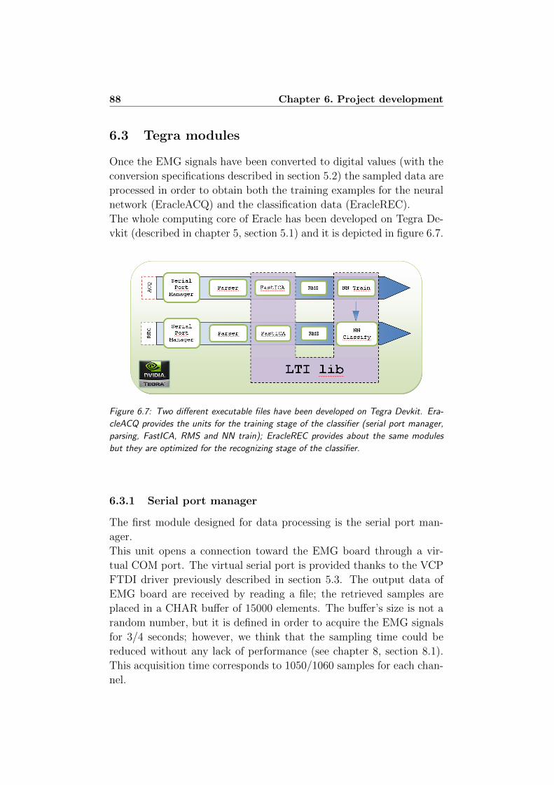
88 Chapter 6. Project development
6.3 Tegra modules
Once the EMG signals have been converted to digital values (with the
conversion specifications described in section 5.2) the sampled data are
processed in order to obtain both the training examples for the neural
network (EracleACQ) and the classification data (EracleREC).
The whole computing core of Eracle has been developed on Tegra De-
vkit (described in chapter 5, section 5.1) and it is depicted in figure 6.7.
Figure 6.7: Two different executable files have been developed on Tegra Devkit. Era-
cleACQ provides the units for the training stage of the classifier (serial port manager,
parsing, FastICA, RMS and NN train); EracleREC provides about the same modules
but they are optimized for the recognizing stage of the classifier.
6.3.1 Serial port manager
The first module designed for data processing is the serial port man-
ager.
This unit opens a connection toward the EMG board through a vir-
tual COM port. The virtual serial port is provided thanks to the VCP
FTDI driver previously described in section 5.3. The output data of
EMG board are received by reading a file; the retrieved samples are
placed in a CHAR buffer of 15000 elements. The buffer’s size is not a
random number, but it is defined in order to acquire the EMG signals
for 3/4 seconds; however, we think that the sampling time could be
reduced without any lack of performance (see chapter 8, section 8.1).
This acquisition time corresponds to 1050/1060 samples for each chan-
nel.

6.3. Tegra modules 89
Once the user has performed the movement, the sampling is stopped,
the virtual COM port is closed and the data held in the CHAR buffer
are written on a file for succeeding processing. The output files look
like the excerpt listed below:
501 509
D:508 509 512
D:508 507 511
D:512 501 511
D:505 507 500
...
...
...
D:498 519 504
I:a b c
D:508 504 517
D:509 507 511
D:511 5
The acquisition procedure is repeated until all the acquisition have
been performed.
The C++ code that handles data acquisition from the EMG board
is listed in appendix A, section A.1. The previous listed output is
the most general one achievable from the EMG board. There are some
spurious data both at the beginning and at the end of the file, moreover
- as already described in section 5.2 - every 100 samples the string I:a
b c is added to the output list.
The next unit deals with such spurious value in the input data.
6.3.2 Data parsing
Once the input data have been acquired from the EMG board, it is
necessary to process them, removing any spurious value. It is also
necessary to split the original input file in three different sources be-
fore processing them with FastICA algorithm. In particular, this unit
performs the main tasks outlined in figure 6.8. Before processing the
input data it is useful to copy the whole contents of the input file to
a STL container like a string. On this kind of data type it is possible
to employ some functions of the Standard Template Libraries, like find
or replace.
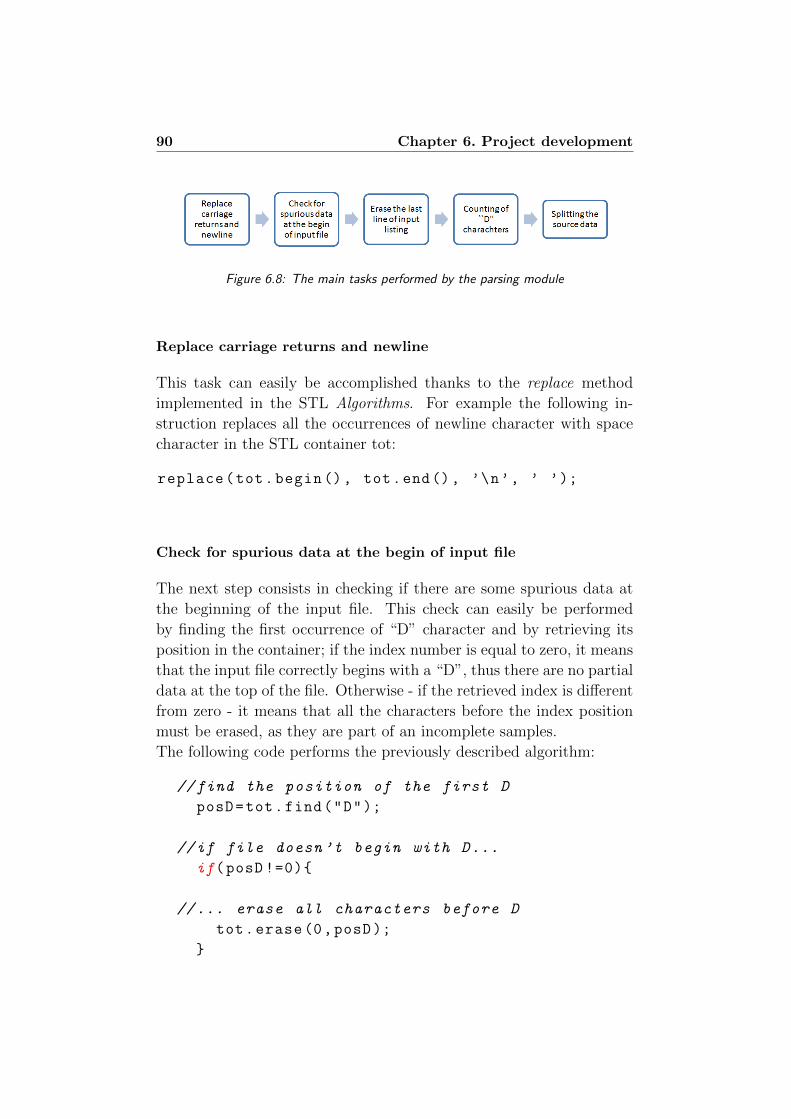
90 Chapter 6. Project development
Figure 6.8: The main tasks performed by the parsing module
Replace carriage returns and newline
This task can easily be accomplished thanks to the replace method
implemented in the STL Algorithms. For example the following in-
struction replaces all the occurrences of newline character with space
character in the STL container tot:
replace(tot.begin(), tot.end(), ’\n’, ’ ’);
Check for spurious data at the begin of input file
The next step consists in checking if there are some spurious data at
the beginning of the input file. This check can easily be performed
by finding the first occurrence of “D” character and by retrieving its
position in the container; if the index number is equal to zero, it means
that the input file correctly begins with a “D”, thus there are no partial
data at the top of the file. Otherwise - if the retrieved index is different
from zero - it means that all the characters before the index position
must be erased, as they are part of an incomplete samples.
The following code performs the previously described algorithm:
//find the position of the first D
posD=tot.find("D");
//if file doesn’t begin with D...
if(posD !=0)
//... erase all characters before D
tot.erase(0,posD);
6.3. Tegra modules 91
Erase the last line of input listing
This operation is necessary to prevent spurious data at the end of input
file.
As we acquire more samples than necessary, it doesn’t matter if one
sample vector is deleted.
To perform this task it is necessary to retrieve the positions of the
last “D” character and of the termination character “/0”, then all the
values between these two indexes are erased.
The following listing performs the described task:
size_t ultimo;
size_t fine;
//get the position of last D...
ultimo = tot.rfind("D");
//... and the position of the termination char
fine = tot.rfind("\0");
/*delete last row,
but don’t erase "\0" character*/
tot.erase(ultimo , fine -1);
This procedure could be optimized by avoiding the erasure of the last
input vector if it is a complete sample. This can easily be performed
by finding the last “D” and then counting the number of spaces before
the termination character. If the number of spaces is less than three,
it means that the sample is not complete and then it must be erased.
Counting of “D” characters
This procedure is not strictly necessary, but it is useful for error check-
ing.
Some experiments and some observations about the maximum memory
load of the Devkit lead us to the considerations that 1010 samples are
widely acceptable for performing movement recognition. This entails
that if (for any reason) the system obtains less than 1010 samples for
each channel, the acquisition procedure is invalid and must be aborted.
This check can easily be performed by counting the occurrences of “D”
92 Chapter 6. Project development
characters in the input file and ensuring that they are greater than
1010. Moreover, it is necessary that all the channels contains exactly
the same number of samples to avoid errors in the following FastICA
processing.
The following code listing implements these considerations:
//numbers of "clean" data acquired
int counter = count(tot.begin(),tot.end(),’D’);
if(counter <1010)
MessageBox(NULL , TEXT("Few samples"),
TEXT("EracleParser"), MB_OK);
exit (0);
Splitting the source data
The last section is the core of this unit: it splits the source data into
three different source files: one for each channel.
The main idea of the algorithm is as following:
• find the first “D” character and retrieve its index (the position
of the first one is surely zero, due to the second step previously
described);
• retrieve the position of the first space;
• copy the characters between the two indexes in the first channel
destination file;
• starting from the first space find the second one and save its index;
• copy the characters between the two indexes in the second channel
destination file;
• starting from the second space find the last space in the triple
(that always exists due to previously described steps one and
three);
• copy the characters between the two indexes in the third channel
destination file.
6.3. Tegra modules 93
This procedure is repeated until all the sampled triples have been split-
ted.
The result consists in three files filled with the sampled values, each
sample is separated only by a white space.
The code that implements this last functionality is quoted in appendix A,
section A.2.
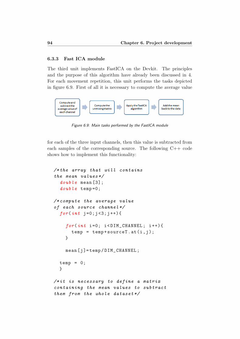
94 Chapter 6. Project development
6.3.3 Fast ICA module
The third unit implements FastICA on the Devkit. The principles
and the purpose of this algorithm have already been discussed in 4.
For each movement repetition, this unit performs the tasks depicted
in figure 6.9. First of all it is necessary to compute the average value
Figure 6.9: Main tasks performed by the FastICA module
for each of the three input channels, then this value is subtracted from
each samples of the corresponding source. The following C++ code
shows how to implement this functionality:
/*the array that will contains
the mean values*/
double mean [3];
double temp =0;
/*compute the average value
of each source channel*/
for(int j=0;j<3;j++)
for(int i=0; i<DIM_CHANNEL; i++)
temp = temp+sourceT.at(i,j);
mean[j]=temp/DIM_CHANNEL;
temp = 0;
/*it is necessary to define a matrix
containing the mean values to subtract
them from the whole dataset*/
6.3. Tegra modules 95
lti::matrix <double > media(1,3,mean);
const double init =1;
lti::matrix <double > ones(DIM_CHANNEL ,1,init);
lti::matrix <double > matmedia;
matmedia.multiply(ones ,media);
/*subtract average values from
the whole dataset*/
sourceT.subtract(matmedia );
Then the ICA algorithm is applied, it separates the source signals that
are overlapped due to the crosstalking between the forearm muscles.
It is important to point out that the unmixing matrix is computed for
every movement repetition, thus for each element of the dataset. This
choice is in contrast with what has been proposed by Naik et al in [43],
as they compute the W matrix only with the first set of samples and
then it is applied to the other repetitions of the same movement. This
choice is unsuitable for Eracle project mainly for two reasons:
• computing the unmixing matrix considering only the first set of
data makes the whole system too much sensible to the quality of
this sample, thus if the first acquisition is performed badly, it will
invalidate all the training process.
• in the project described by Naik in [43], the data employed for
training and classification are sampled at the same time, thus
during the same session. In Eracle the user can train the device
and use it for recognition in completely different times.
So the W matrix can’t be constant, as it is different for each movement,
and selecting the more appropriate one before starting the recognition
procedure would entail that the device already knows the gesture that
the user will perform.
FastICA algorithm is a feature available in LTIlib and it can be applied
as stated in the following code excerpt:
//FastICA object
lti::fastICA <double > ica;

96 Chapter 6. Project development
//unmixing matrix
lti:: matrix <double > unMat;
/*apply the ICA algorithm to the data
saved in source matrix.
Result is stored in clean matrix*/
ica.apply(source ,clean);
//print the transformation matrix
ica.getTransformMatrix(constTransfMatrix );
The last step consists is adding the mean back to the data, more pre-
cisely it applies the following formula to the output values of FastICA
algorithm:
output = W×unMixedSignal+(W×mixedMean)×ones(1, NumOfSamples)
where:
• W is the unmixing matrix computed by ICA;
• unMixedSignal is the matrix filled with the output data of Fas-
tICA algorithm;
• mixedMean is the vector containing the average values of the
source data;
• ones(1,NumOfSamples) is a vector with number of columns equal
to the number of samples acquired, filled with the number one.
The following code listing implements the described equation:
//first member of equation
lti::matrix <double > first;
/*((1))first = W*unmixedsig*/
/*unMixedSignal matrix must be transposed
in cleanT to be multiplied*/
lti::matrix <double > cleanT;
cleanT.transpose(unMixedSignal );
first.multiply(constTransfMatrix ,cleanT );
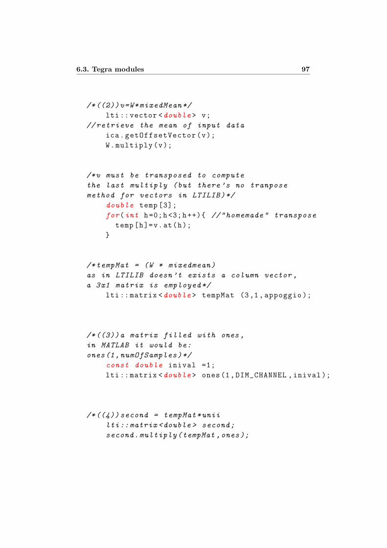
6.3. Tegra modules 97
/*((2))v=W*mixedMean*/
lti::vector <double > v;
//retrieve the mean of input data
ica.getOffsetVector(v);
W.multiply(v);
/*v must be transposed to compute
the last multiply (but there’s no tranpose
method for vectors in LTILIB)*/
double temp [3];
for(int h=0;h<3;h++) //"homemade" transpose
temp[h]=v.at(h);
/*tempMat = (W * mixedmean)
as in LTILIB doesn’t exists a column vector ,
a 3x1 matrix is employed*/
lti::matrix <double > tempMat (3,1, appoggio );
/*((3))a matrix filled with ones ,
in MATLAB it would be:
ones(1,numOfSamples)*/
const double inival =1;
lti::matrix <double > ones(1,DIM_CHANNEL ,inival );
/*((4))second = tempMat*unii
lti::matrix <double > second;
second.multiply(tempMat ,ones);
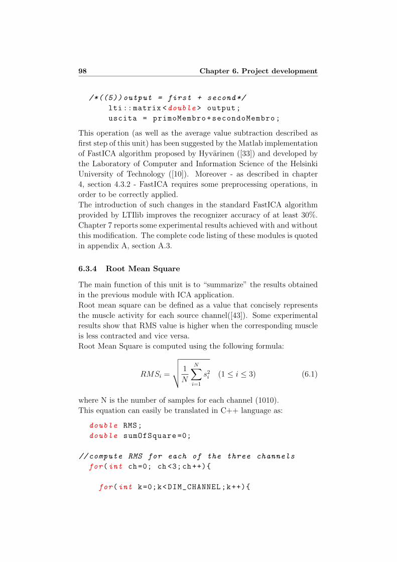
98 Chapter 6. Project development
/*((5)) output = first + second*/
lti::matrix <double > output;
uscita = primoMembro+secondoMembro;
This operation (as well as the average value subtraction described as
first step of this unit) has been suggested by the Matlab implementation
of FastICA algorithm proposed by Hyvarinen ([33]) and developed by
the Laboratory of Computer and Information Science of the Helsinki
University of Technology ([10]). Moreover - as described in chapter
4, section 4.3.2 - FastICA requires some preprocessing operations, in
order to be correctly applied.
The introduction of such changes in the standard FastICA algorithm
provided by LTIlib improves the recognizer accuracy of at least 30%.
Chapter 7 reports some experimental results achieved with and without
this modification. The complete code listing of these modules is quoted
in appendix A, section A.3.
6.3.4 Root Mean Square
The main function of this unit is to “summarize” the results obtained
in the previous module with ICA application.
Root mean square can be defined as a value that concisely represents
the muscle activity for each source channel([43]). Some experimental
results show that RMS value is higher when the corresponding muscle
is less contracted and vice versa.
Root Mean Square is computed using the following formula:
RMSi =
√√√√ 1
N
N∑i=1
s2i (1 ≤ i ≤ 3) (6.1)
where N is the number of samples for each channel (1010).
This equation can easily be translated in C++ language as:
double RMS;
double sumOfSquare =0;
//compute RMS for each of the three channels
for(int ch=0; ch <3;ch++)
for(int k=0;k<DIM_CHANNEL;k++)
6.3. Tegra modules 99
sumOfSquare=sumOfSquare +
pow(clean_source.at(ch,k),2);
RMS = sqrt(sumOfSquare/DIM_CHANNEL );
RMS =0;
sumOfSquare =0;
where DIM CHANNEL is a constant value that defines the number ofsamples for each channel.It is computed for each channel for every movement repetition; thus, ifthe user performs 20 movements, we obtain 60 RMS values. These dataare saved in a file according to the pattern: RMSch1rep1 RMSch2rep1
RMSch3rep1 . . .
The RMS values obtained from the repetitions of the same movement are stored in
a file whose name identifies the movement performed by the user. The indexes that
identify the performed movement depend on the number of gestures that the device
will recognize. For the final prototype of Eracle, we’ve proposed the five gestures
described in chapter 3, section 3.1, which are:
• close hand: which corresponds to index 0;
• wrist extension: which corresponds to index 1;
• wrist flexion: which corresponds to index 2;
• open hand: which corresponds to index 3;
• click: which corresponds to index 4.
For example, all the RMS computed for every repetition of the gesture “close hand”
are saved in a file named RMSmov0.
The complete code listing can be found in A, section A.4.
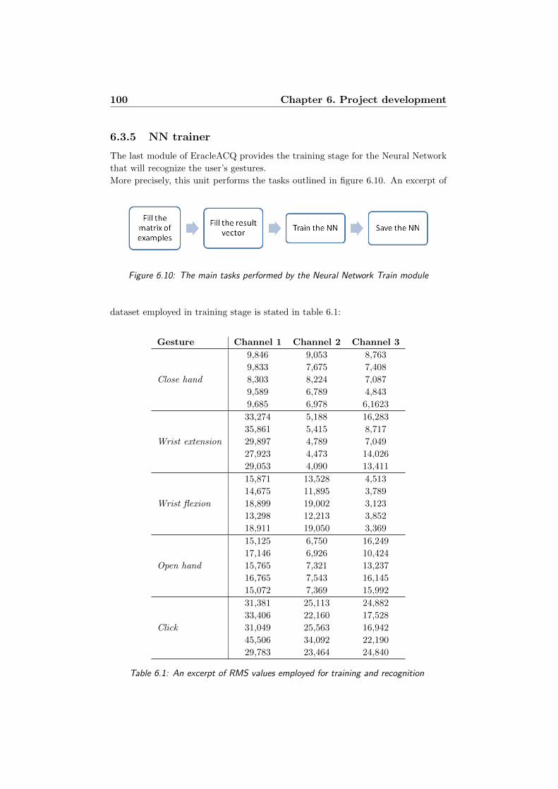
100 Chapter 6. Project development
6.3.5 NN trainer
The last module of EracleACQ provides the training stage for the Neural Network
that will recognize the user’s gestures.
More precisely, this unit performs the tasks outlined in figure 6.10. An excerpt of
Figure 6.10: The main tasks performed by the Neural Network Train module
dataset employed in training stage is stated in table 6.1:
Gesture Channel 1 Channel 2 Channel 3
Close hand
9,846 9,053 8,763
9,833 7,675 7,408
8,303 8,224 7,087
9,589 6,789 4,843
9,685 6,978 6,1623
Wrist extension
33,274 5,188 16,283
35,861 5,415 8,717
29,897 4,789 7,049
27,923 4,473 14,026
29,053 4,090 13,411
Wrist flexion
15,871 13,528 4,513
14,675 11,895 3,789
18,899 19,002 3,123
13,298 12,213 3,852
18,911 19,050 3,369
Open hand
15,125 6,750 16,249
17,146 6,926 10,424
15,765 7,321 13,237
16,765 7,543 16,145
15,072 7,369 15,992
Click
31,381 25,113 24,882
33,406 22,160 17,528
31,049 25,563 16,942
45,506 34,092 22,190
29,783 23,464 24,840
Table 6.1: An excerpt of RMS values employed for training and recognition
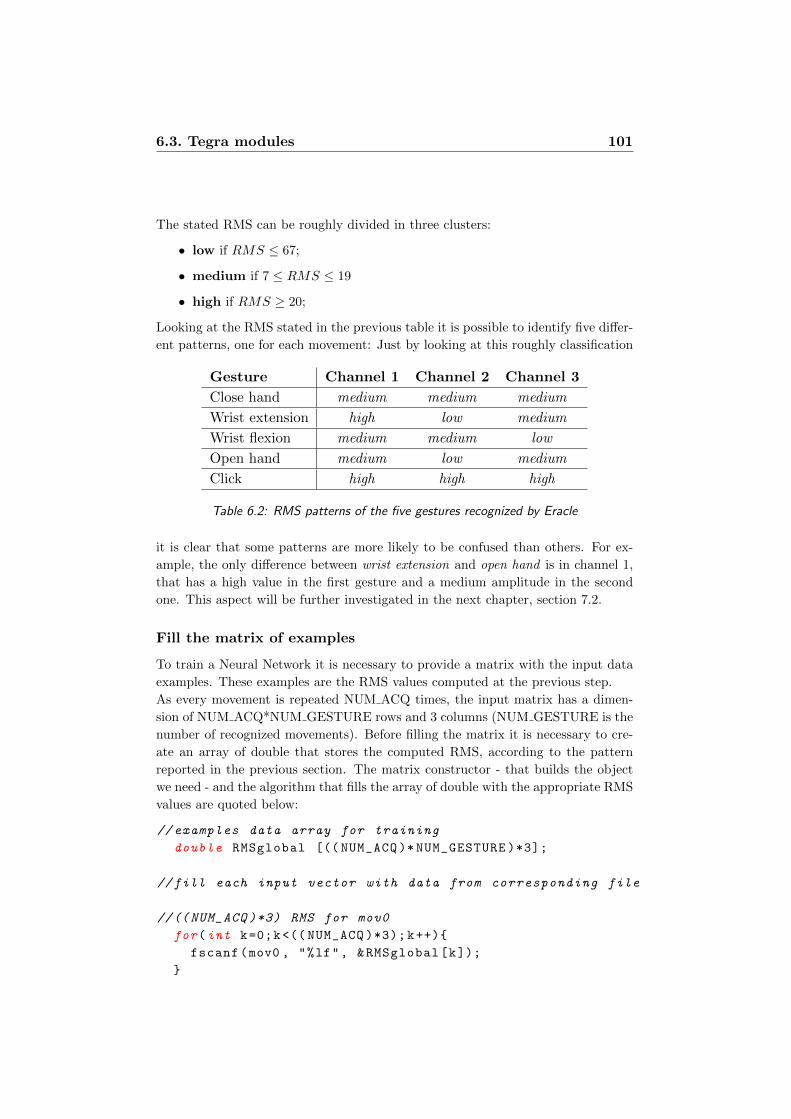
6.3. Tegra modules 101
The stated RMS can be roughly divided in three clusters:
• low if RMS ≤ 67;
• medium if 7 ≤ RMS ≤ 19
• high if RMS ≥ 20;
Looking at the RMS stated in the previous table it is possible to identify five differ-
ent patterns, one for each movement: Just by looking at this roughly classification
Gesture Channel 1 Channel 2 Channel 3
Close hand medium medium medium
Wrist extension high low medium
Wrist flexion medium medium low
Open hand medium low medium
Click high high high
Table 6.2: RMS patterns of the five gestures recognized by Eracle
it is clear that some patterns are more likely to be confused than others. For ex-
ample, the only difference between wrist extension and open hand is in channel 1,
that has a high value in the first gesture and a medium amplitude in the second
one. This aspect will be further investigated in the next chapter, section 7.2.
Fill the matrix of examples
To train a Neural Network it is necessary to provide a matrix with the input data
examples. These examples are the RMS values computed at the previous step.
As every movement is repeated NUM ACQ times, the input matrix has a dimen-
sion of NUM ACQ*NUM GESTURE rows and 3 columns (NUM GESTURE is the
number of recognized movements). Before filling the matrix it is necessary to cre-
ate an array of double that stores the computed RMS, according to the pattern
reported in the previous section. The matrix constructor - that builds the object
we need - and the algorithm that fills the array of double with the appropriate RMS
values are quoted below:
// examples data array for training
double RMSglobal [(( NUM_ACQ )* NUM_GESTURE )*3];
//fill each input vector with data from corresponding file
//(( NUM_ACQ )*3) RMS for mov0
for(int k=0;k<(( NUM_ACQ )*3);k++)
fscanf(mov0 , "%lf", &RMSglobal[k]);
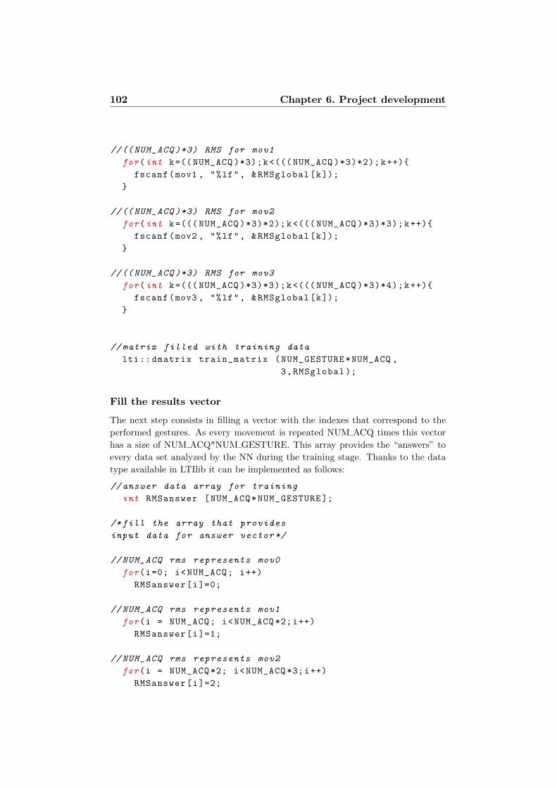
102 Chapter 6. Project development
//(( NUM_ACQ )*3) RMS for mov1
for(int k=(( NUM_ACQ )*3);k<((( NUM_ACQ )*3)*2);k++)
fscanf(mov1 , "%lf", &RMSglobal[k]);
//(( NUM_ACQ )*3) RMS for mov2
for(int k=((( NUM_ACQ )*3)*2);k<((( NUM_ACQ )*3)*3);k++)
fscanf(mov2 , "%lf", &RMSglobal[k]);
//(( NUM_ACQ )*3) RMS for mov3
for(int k=((( NUM_ACQ )*3)*3);k<((( NUM_ACQ )*3)*4);k++)
fscanf(mov3 , "%lf", &RMSglobal[k]);
// matrix filled with training data
lti:: dmatrix train_matrix (NUM_GESTURE*NUM_ACQ ,
3,RMSglobal );
Fill the results vector
The next step consists in filling a vector with the indexes that correspond to the
performed gestures. As every movement is repeated NUM ACQ times this vector
has a size of NUM ACQ*NUM GESTURE. This array provides the “answers” to
every data set analyzed by the NN during the training stage. Thanks to the data
type available in LTIlib it can be implemented as follows:
// answer data array for training
int RMSanswer [NUM_ACQ*NUM_GESTURE ];
/*fill the array that provides
input data for answer vector */
// NUM_ACQ rms represents mov0
for(i=0; i<NUM_ACQ; i++)
RMSanswer[i]=0;
// NUM_ACQ rms represents mov1
for(i = NUM_ACQ; i<NUM_ACQ *2;i++)
RMSanswer[i]=1;
// NUM_ACQ rms represents mov2
for(i = NUM_ACQ *2; i<NUM_ACQ *3;i++)
RMSanswer[i]=2;
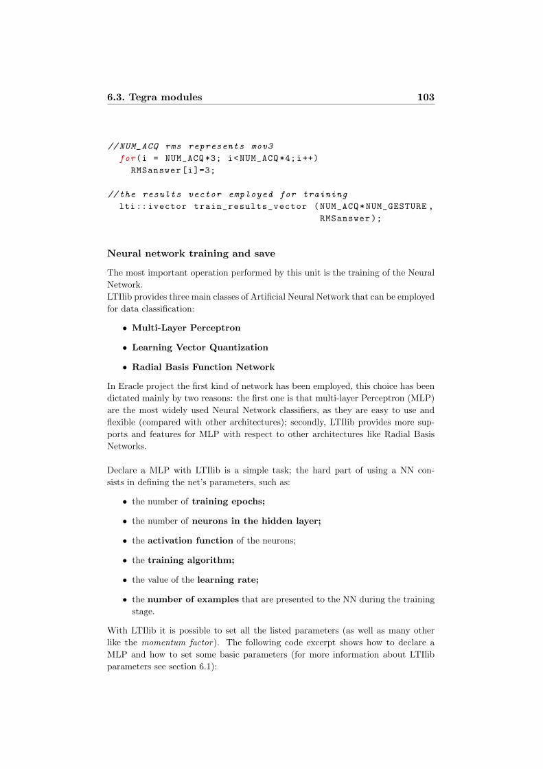
6.3. Tegra modules 103
// NUM_ACQ rms represents mov3
for(i = NUM_ACQ *3; i<NUM_ACQ *4;i++)
RMSanswer[i]=3;
//the results vector employed for training
lti:: ivector train_results_vector (NUM_ACQ*NUM_GESTURE ,
RMSanswer );
Neural network training and save
The most important operation performed by this unit is the training of the Neural
Network.
LTIlib provides three main classes of Artificial Neural Network that can be employed
for data classification:
• Multi-Layer Perceptron
• Learning Vector Quantization
• Radial Basis Function Network
In Eracle project the first kind of network has been employed, this choice has been
dictated mainly by two reasons: the first one is that multi-layer Perceptron (MLP)
are the most widely used Neural Network classifiers, as they are easy to use and
flexible (compared with other architectures); secondly, LTIlib provides more sup-
ports and features for MLP with respect to other architectures like Radial Basis
Networks.
Declare a MLP with LTIlib is a simple task; the hard part of using a NN con-
sists in defining the net’s parameters, such as:
• the number of training epochs;
• the number of neurons in the hidden layer;
• the activation function of the neurons;
• the training algorithm;
• the value of the learning rate;
• the number of examples that are presented to the NN during the training
stage.
With LTIlib it is possible to set all the listed parameters (as well as many other
like the momentum factor). The following code excerpt shows how to declare a
MLP and how to set some basic parameters (for more information about LTIlib
parameters see section 6.1):
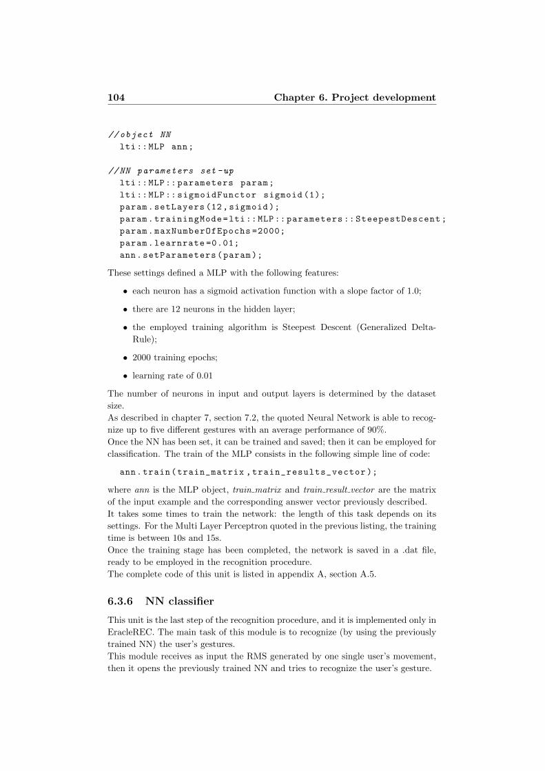
104 Chapter 6. Project development
// object NN
lti::MLP ann;
//NN parameters set -up
lti::MLP:: parameters param;
lti::MLP:: sigmoidFunctor sigmoid (1);
param.setLayers (12, sigmoid );
param.trainingMode=lti::MLP:: parameters :: SteepestDescent;
param.maxNumberOfEpochs =2000;
param.learnrate =0.01;
ann.setParameters(param);
These settings defined a MLP with the following features:
• each neuron has a sigmoid activation function with a slope factor of 1.0;
• there are 12 neurons in the hidden layer;
• the employed training algorithm is Steepest Descent (Generalized Delta-
Rule);
• 2000 training epochs;
• learning rate of 0.01
The number of neurons in input and output layers is determined by the dataset
size.
As described in chapter 7, section 7.2, the quoted Neural Network is able to recog-
nize up to five different gestures with an average performance of 90%.
Once the NN has been set, it can be trained and saved; then it can be employed for
classification. The train of the MLP consists in the following simple line of code:
ann.train(train_matrix ,train_results_vector );
where ann is the MLP object, train matrix and train result vector are the matrix
of the input example and the corresponding answer vector previously described.
It takes some times to train the network: the length of this task depends on its
settings. For the Multi Layer Perceptron quoted in the previous listing, the training
time is between 10s and 15s.
Once the training stage has been completed, the network is saved in a .dat file,
ready to be employed in the recognition procedure.
The complete code of this unit is listed in appendix A, section A.5.
6.3.6 NN classifier
This unit is the last step of the recognition procedure, and it is implemented only in
EracleREC. The main task of this module is to recognize (by using the previously
trained NN) the user’s gestures.
This module receives as input the RMS generated by one single user’s movement,
then it opens the previously trained NN and tries to recognize the user’s gesture.
6.3. Tegra modules 105
Open the previously trained NN is a simple task, due to the lispStreamHandler
provided by LTIlib; it is an interface for LTIlib classes to read and write them in a
LISP-like format.
The listing below shows how to load the trained MLP:
/*NN used for recognition */
lti::MLP annc;
//path to the NN file
std:: ifstream inNN("...\\ TrainedNN.dat");
// stream handler for reading
lti:: lispStreamHandler lsh_c(inNN);
//read NN settings from file and close it
annc.read(lsh_c);
inNN.close ();
At the end of this procedure, the MLP called annc has inherited all the “experience”
of the previously trained matrix.
The next step consists in building an output classification vector and an input
feature vector with the data to process:
//the vector that will contains the MLP answer
lti::MLP:: outputVector result;
//the vector containing the feature to classify
lti:: dvector feature_to_classify (3, NN_class_data );
where NN class data is an array of double containing the three RMS generated for
the user’s movement.
Note that the output vector is not a generic array, but it is an object of outputVec-
tor class; this structure is a special data type designed to give some information
about the classification result of the network (e.g. the classification confidence).
In the last step, the MLP classify the provided dataset, filling the previously de-
scribed outputVector:
// perform classification
annc.classify(feature_to_classify ,result );
Once the performed gesture has been identified, it can be displayed on the screen
or employed to control an application.

106 Chapter 6. Project development
Chapter 7
Steps in testing and final
results
“Spock: Don’t grieve, Admiral. It is logical. The needs of the many out-
weigh...
Kirk: ... the needs of the few.
Spock: ... or the one. I never took the Kobayashi Maru test. Until now.
What do you think of my solution?
I have been, and always shall be your friend.
Live long... and prosper.”
Star Trek II - The Wrath of Khan
Once all the units of Eracle have been developed, some tests have been executed,
to estimate the system performance. The first paragraph of this chapter describes
the procedure that has been adopted for all the trials.
Many tests have been carried out during the project development (we’ve performed
about 100 different trials), however we would like to give an idea of how the project
has evolved and which are the experimental results that have lead us to the achieve-
ment of a fully mobile device that correctly identifies at least five different gestures.
The second section of this chapter provides some experimental results presented
following this point of view.
7.1 Test procedure
First of all it is necessary that the user wears the acquisition glove (described in
chapter 6, section 6.2) that will be connected to the devkit (described in chapter
5, section 5.1). The acquisition glove ensures repeatability during all the experi-
ment. It means that we have to be sure that the electrodes are always placed nearly
the same position, even if some time has elapsed between training and recognition
stage. This feature of acquisition glove will be demonstrated in the next section.
108 Chapter 7. Steps in testing and final results
Test stage is mainly divided in two different phases: training and classifying.
Training stage
This step is fully handled by EracleACQ, the executable file described in chapter
3, section 3.3.
During training stage, the user performs each movement several times to train
the Neural Network classifier. Up to five gestures have been employed to test
the application. Depending on the recognizer settings (see next section), every
movement have been executed between 5 and 20 times.
The user can perform the training movements either standing or sitting.
Eracle has been tested with five different gestures:
• close hand;
• wrist extension;
• wrist flexion;
• open hand;
• click.
These movements have already been described in chapter 3, section 3.1.
Once the user has performed the requested repetitions of one movement, he rests his
forearm since the muscular fatigue could invalidate the sampled acquired (see B).
During this break, the computing core of Eracle processes the sampled data. As
previously described in chapter 6, the whole processing chain of the training stage
consists in:
• parsing: each input data file is splitted into three different sources;
• FastICA: that filters the sampled signals;
• RMS: that computes the Root Mean Square value for each source channel of
each repetition;
Once this process has been repeated for all the gestures, the Neural Network is
trained using the previously computed RMS values. The training time depends on
the Neural Network settings; the classifier employed in the last set of tests (that is
able to recognize up to five different gestures) needs between 10s and 15s for the
training stage.
At the end of this stage EracleACQ generates a .dat file that stores the weights of
the trained Neural Network.
Recognition stage
This step is fully handled by EracleREC, the executable file described in chapter
3, section 3.3.
In this stage the user performs just one movement (among those used for training)
7.1. Test procedure 109
and the device tries to recognize it.
To test the application, the users repeat each gesture alternately for ten times.
At the end of the ten repetitions of each gesture, the average success rate of
the test is computed. Both in training and in recognition stage, the user should
performs the gestures in a natural way, it means without “force” the movement.
However, Eracle has demonstrated to be robust with respect to this feature. In
fact, all the results provided in the next section have been achieved by executing
the movement with different strength.

110 Chapter 7. Steps in testing and final results
7.2 Results
During the test stage, we mainly focused on the recognizer’s performance in order
to identify the best settings for Neural Network and FastICA algorithm. It entails
that almost all the test described in this chapter are referred to the same subject
with these characteristics:
• Gender: Male
• Age: 24
• Height: 177 cm
• Weight: 68 kg
• B.M.I: 22
The last value is the Body Mass Index that briefly describes the physique of the
user. B.M.I. between 18,5 and 25 identifies a medium-build man.
7.2.1 First set of tests: two gestures
In the first set of tests the user performs only two movements: close hand and wrist
extension.
The neural network classifier has been set as follows:
• 3 input neurons, 2 output neurons;
• 6 neurons in the hidden layer;
• 2000 training epochs;
• learning rate: 0,1;
• learning algorithm: generalized Delta Rule (Backpropagation) .
The number of neurons in the hidden layer has been set according to the following
thumb rule:
HiddenNeurons = InputNeurons × OutputNeurons (7.1)
Each movement has been repeated 10 times during the training process. In this
trial no additional preprocessing or postprocessing have been added to FastICA
module, thus we employ the FastICA algorithm provided by LTIlib “as it is”.
Matrix W has been kept constant for each gesture during all the training process.
The results of this test are shown in table 7.1.
Gesture Success/Tot Errors/Tot Test performance
Close 8/10 2/1060%
Wrist extension 4/10 6/10
Table 7.1: Results of the first test; in FastICA algorithm matrix W has been kept
constant
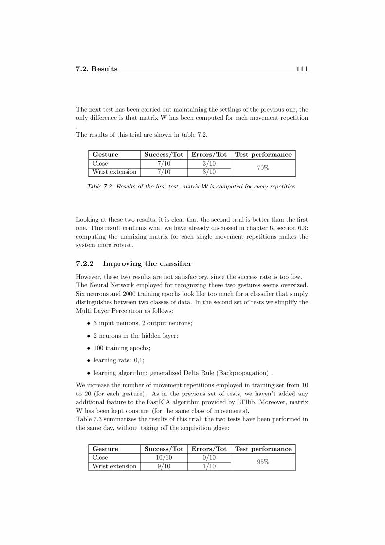
7.2. Results 111
The next test has been carried out maintaining the settings of the previous one, the
only difference is that matrix W has been computed for each movement repetition
.
The results of this trial are shown in table 7.2.
Gesture Success/Tot Errors/Tot Test performance
Close 7/10 3/1070%
Wrist extension 7/10 3/10
Table 7.2: Results of the first test, matrix W is computed for every repetition
Looking at these two results, it is clear that the second trial is better than the first
one. This result confirms what we have already discussed in chapter 6, section 6.3:
computing the unmixing matrix for each single movement repetitions makes the
system more robust.
7.2.2 Improving the classifier
However, these two results are not satisfactory, since the success rate is too low.
The Neural Network employed for recognizing these two gestures seems oversized.
Six neurons and 2000 training epochs look like too much for a classifier that simply
distinguishes between two classes of data. In the second set of tests we simplify the
Multi Layer Perceptron as follows:
• 3 input neurons, 2 output neurons;
• 2 neurons in the hidden layer;
• 100 training epochs;
• learning rate: 0,1;
• learning algorithm: generalized Delta Rule (Backpropagation) .
We increase the number of movement repetitions employed in training set from 10
to 20 (for each gesture). As in the previous set of tests, we haven’t added any
additional feature to the FastICA algorithm provided by LTIlib. Moreover, matrix
W has been kept constant (for the same class of movements).
Table 7.3 summarizes the results of this trial; the two tests have been performed in
the same day, without taking off the acquisition glove:
Gesture Success/Tot Errors/Tot Test performance
Close 10/10 0/1095%
Wrist extension 9/10 1/10
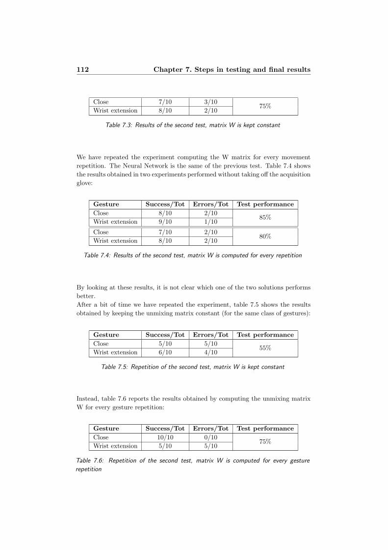
112 Chapter 7. Steps in testing and final results
Close 7/10 3/1075%
Wrist extension 8/10 2/10
Table 7.3: Results of the second test, matrix W is kept constant
We have repeated the experiment computing the W matrix for every movement
repetition. The Neural Network is the same of the previous test. Table 7.4 shows
the results obtained in two experiments performed without taking off the acquisition
glove:
Gesture Success/Tot Errors/Tot Test performance
Close 8/10 2/1085%
Wrist extension 9/10 1/10
Close 7/10 2/1080%
Wrist extension 8/10 2/10
Table 7.4: Results of the second test, matrix W is computed for every repetition
By looking at these results, it is not clear which one of the two solutions performs
better.
After a bit of time we have repeated the experiment, table 7.5 shows the results
obtained by keeping the unmixing matrix constant (for the same class of gestures):
Gesture Success/Tot Errors/Tot Test performance
Close 5/10 5/1055%
Wrist extension 6/10 4/10
Table 7.5: Repetition of the second test, matrix W is kept constant
Instead, table 7.6 reports the results obtained by computing the unmixing matrix
W for every gesture repetition:
Gesture Success/Tot Errors/Tot Test performance
Close 10/10 0/1075%
Wrist extension 5/10 5/10
Table 7.6: Repetition of the second test, matrix W is computed for every gesture
repetition

7.2. Results 113
By looking at these two last results it is clear that keeping the unmixing matrix
constant brings to a lack of performance of the recognizer. This result definitively
confirms the hypothesis formulated in chapter 6, section 6.3: computing the un-
mixing matrix for each single movement repetitions makes the system more robust.
7.2.3 From two to four gestures
By working with only two movements we have found that the unmixing matrix W
must be kept constant for all the repetitions of the same gesture during the training
stage. However, a gesture recognition device that distinguishes only between two
gestures is not very useful.
The next goal is to raise the number of recognized gestures from two to at least
four.
Table 7.7 shows the results obtained with the same architecture employed in the
previous test working on three gestures (close hand, wrist extension and wrist flex-
ion). There are only two differences between this solution and the previous one:
• the number of hidden neurons has been increased to 9 (following the thumb
rule quoted in equation 7.1);
• the number of training epochs has been increased to 500;
Gesture Success/Tot Errors/Tot Test performance
Close 5/10 5/10
53%Wrist extension 8/10 2/10
Wrist flexion 3/10 7/10
Table 7.7: Third test: the Neural Network tries to classify three different gestures
Performance gets even worse if we use the same recognizer on four different gestures
(adding open hand movement), as shown in table 7.8:
Gesture Success/Tot Errors/Tot Test performance
Close 3/10 7/10
38%Wrist extension 0/10 10/10
Wrist flexion 7/10 3/10
Open hand 5/10 5/10
Table 7.8: Third test: the Neural Network tries to classify four different gestures
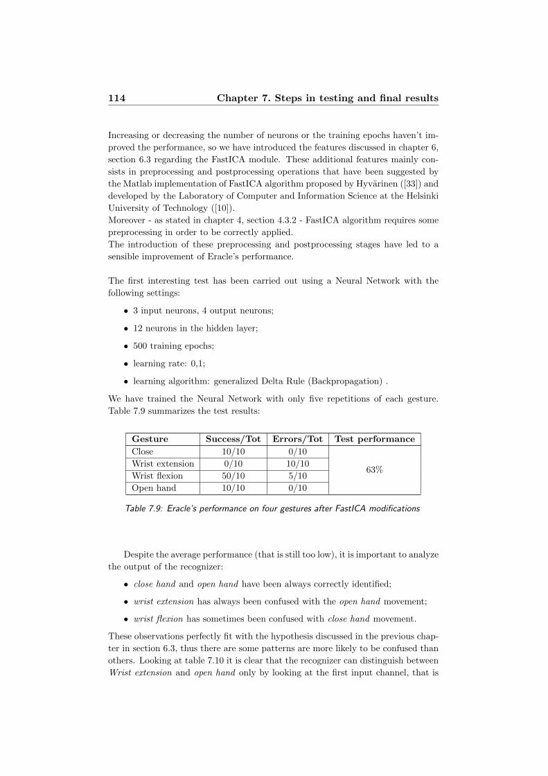
114 Chapter 7. Steps in testing and final results
Increasing or decreasing the number of neurons or the training epochs haven’t im-
proved the performance, so we have introduced the features discussed in chapter 6,
section 6.3 regarding the FastICA module. These additional features mainly con-
sists in preprocessing and postprocessing operations that have been suggested by
the Matlab implementation of FastICA algorithm proposed by Hyvarinen ([33]) and
developed by the Laboratory of Computer and Information Science at the Helsinki
University of Technology ([10]).
Moreover - as stated in chapter 4, section 4.3.2 - FastICA algorithm requires some
preprocessing in order to be correctly applied.
The introduction of these preprocessing and postprocessing stages have led to a
sensible improvement of Eracle’s performance.
The first interesting test has been carried out using a Neural Network with the
following settings:
• 3 input neurons, 4 output neurons;
• 12 neurons in the hidden layer;
• 500 training epochs;
• learning rate: 0,1;
• learning algorithm: generalized Delta Rule (Backpropagation) .
We have trained the Neural Network with only five repetitions of each gesture.
Table 7.9 summarizes the test results:
Gesture Success/Tot Errors/Tot Test performance
Close 10/10 0/10
63%Wrist extension 0/10 10/10
Wrist flexion 50/10 5/10
Open hand 10/10 0/10
Table 7.9: Eracle’s performance on four gestures after FastICA modifications
Despite the average performance (that is still too low), it is important to analyze
the output of the recognizer:
• close hand and open hand have been always correctly identified;
• wrist extension has always been confused with the open hand movement;
• wrist flexion has sometimes been confused with close hand movement.
These observations perfectly fit with the hypothesis discussed in the previous chap-
ter in section 6.3, thus there are some patterns are more likely to be confused than
others. Looking at table 7.10 it is clear that the recognizer can distinguish between
Wrist extension and open hand only by looking at the first input channel, that is

7.2. Results 115
higher in the first gesture. It is also easy to make a mistake between close hand
and wrist flexion since the only difference between these two gestures is the value
of the third channel, that is higher in the first movement.
Gesture Channel 1 Channel 2 Channel 3
Close hand
9,846 9,053 8,763
9,833 7,675 7,408
8,303 8,224 7,087
9,589 6,789 4,843
9,685 6,978 6,1623
Wrist extension
33,274 5,188 16,283
35,861 5,415 8,717
29,897 4,789 7,049
27,923 4,473 14,026
29,053 4,090 13,411
Wrist flexion
15,871 13,528 4,513
14,675 11,895 3,789
18,899 19,002 3,123
13,298 12,213 3,852
18,911 19,050 3,369
Open hand
15,125 6,750 16,249
17,146 6,926 10,424
15,765 7,321 13,237
16,765 7,543 16,145
15,072 7,369 15,992
Table 7.10: An excerpt of RMS values employed for training and recognition
The described classifier (with only two neurons in the output layer) can easily
distinguish between wrist extension and close hand movements, as outlined by
table 7.11:
Gesture Success/Tot Errors/Tot Test performance
Close 10/10 0/10100%
Wrist extension 10/10 0/10
Table 7.11: Eracle’s performance in recognizing two different gestures
The following step consists in adding a new movement to the set of gesture that
will be classified by Eracle. To distinguish among three different movements it is

116 Chapter 7. Steps in testing and final results
necessary to make the network more “sensitive” to the differences described above.
To achieve this result the training epochs have been increased and the learning
rate has been decreased. This last choice will lead to a lack in performance during
the training stage, but it avoids that the training algorithm converges to a local
minimum.
We have selected open hand as additional gesture. The Neural Network has been
set as follows:
• 3 input neurons, 3 output neurons;
• 12 neurons in the hidden layer;
• 1000 training epochs;
• learning rate: 0,01;
• learning algorithm: generalized Delta Rule (Backpropagation) .
We employ 10 repetitions of each gesture during the training stage.
The test results are summarized in table 7.12:
Gesture Success/Tot Errors/Tot Test performance
Close 10/10 0/10
93%Wrist extension 9/10 1/10
Open hand 9/10 1/10
Table 7.12: Eracle’s performance on three different movements
In the last step of this test stage, we have also added the wrist flexion gesture to the
set of movements that will be classified by Eracle. There’s practically no differences
between this classifier and the previous one except the number of output neurons
(that has been increased to four) and the number of training epochs (that has been
increased to 1000).
Table 7.13 shows the test results:
Gesture Success/Tot Errors/Tot Test performance
Close 10/10 0/10
85%Wrist extension 9/10 1/10
Wrist flexion 10/10 0/10
Open hand 5/10 5/10
Table 7.13: Eracle’s performance on four gestures
To improve the recognizer performance we have increased the training epochs to
1500. Also in this trial, the Neural Network has been trained with 10 repetitions
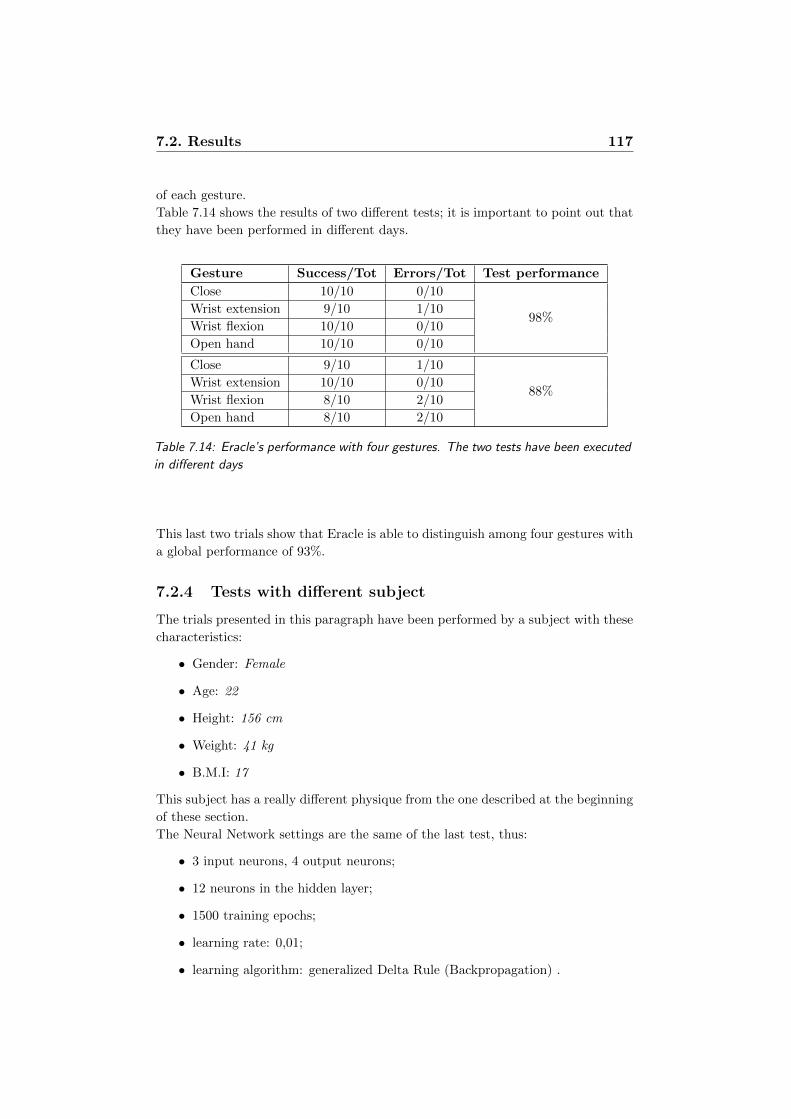
7.2. Results 117
of each gesture.
Table 7.14 shows the results of two different tests; it is important to point out that
they have been performed in different days.
Gesture Success/Tot Errors/Tot Test performance
Close 10/10 0/10
98%Wrist extension 9/10 1/10
Wrist flexion 10/10 0/10
Open hand 10/10 0/10
Close 9/10 1/10
88%Wrist extension 10/10 0/10
Wrist flexion 8/10 2/10
Open hand 8/10 2/10
Table 7.14: Eracle’s performance with four gestures. The two tests have been executed
in different days
This last two trials show that Eracle is able to distinguish among four gestures with
a global performance of 93%.
7.2.4 Tests with different subject
The trials presented in this paragraph have been performed by a subject with these
characteristics:
• Gender: Female
• Age: 22
• Height: 156 cm
• Weight: 41 kg
• B.M.I: 17
This subject has a really different physique from the one described at the beginning
of these section.
The Neural Network settings are the same of the last test, thus:
• 3 input neurons, 4 output neurons;
• 12 neurons in the hidden layer;
• 1500 training epochs;
• learning rate: 0,01;
• learning algorithm: generalized Delta Rule (Backpropagation) .

118 Chapter 7. Steps in testing and final results
Concerning the first test, the Neural Network has been trained with the example
set of the first subject (10 repetitions for each movement). Since the physique of
the two subjects is very different, we haven’t obtained very good results, as shown
in table 7.15:
Gesture Success/Tot Errors/Tot Test performance
Close 10/10 0/10
55%Wrist extension 10/10 0/10
Wrist flexion 2/10 8/10
Open hand 0/10 10/10
Table 7.15: Eracle’s performance with four gestures: the classifier has not been trained
with the data of the current user
Once the second subject has trained the Neural Network with its own data, we have
performed another test with the following results:
Gesture Success/Tot Errors/Tot Test performance
Close 10/10 0/10
85%Wrist extension 9/10 1/10
Wrist flexion 9/10 1/10
Open hand 6/10 4/10
Table 7.16: Eracle’s performance with four gestures: the neural network has been
trained by the current user
In the last test we have increased the number of training epochs from 1500 to 2000,
table 7.17 shows the trial results:
Gesture Success/Tot Errors/Tot Test performance
Close 10/10 0/10
93%Wrist extension 10/10 0/10
Wrist flexion 10/10 0/10
Open hand 7/10 3/10
Table 7.17: Eracle’s performance with four gestures: the number of epochs has been
increased
These last results outline that Eracle is able to distinguish among four different
gestures with a good success rate (about 90%). This result is really meaningful, as

7.2. Results 119
the second subject has never employed a gesture recognition system.
This trial also points out the relevance of employing a correct set of data in the
training stage.
7.2.5 Last set of tests: five gestures
In this last paragraph, Eracle has been tested in recognizing five different move-
ments.
The fifth gesture is called “click”, as it could be employed as the left click of a
mouse (as described in chapter 3, section 3.1. These tests have been performed by
the first user described at the beginning of this section.
For this set of tests, the Neural Network has been set as follows:
• 3 input neurons, 4 output neurons;
• 12 neurons in the hidden layer;
• 2000 training epochs;
• learning rate: 0,01;
• learning algorithm: generalized Delta Rule (Backpropagation) .
Every movement has been performed ten times during the training stage.
Table 7.18 shows the result of two trials that have been performed in different times.
Gesture Success/Tot Errors/Tot Test performance
Close 10/10 0/10
95%
Wrist extension 10/10 0/10
Wrist flexion 9/10 1/10
Open hand 9/10 1/10
Click 7/10 3/10
Close 9/10 1/10
88%
Wrist extension 9/10 1/10
Wrist flexion 9/10 1/10
Open hand 8/10 2/10
Click 7/10 3/10
Table 7.18: Eracle’s performance in classifying five gestures
Eracle has achieved a global performance of about 90% in recognizing five different
gestures. Note that the classifier is approximately the same employed to recognize
four gestures performed by the first subject.
This leads us to the consideration that the device should be able to recognize more
than five gestures with a good performance rate (see chapter 8, section 8.1).

120 Chapter 7. Steps in testing and final results
Chapter 8
Conclusions and future
developments
Chekov: Course heading, Captain?
Kirk: Second star to the right. And straight on ’til morning.
Captain’s log. Stardate 9529.1. This is the final cruise of the starship En-
terprise under my command. This ship and her history will shortly become
the care of another crew. To them and to their posterity we will commit our
future. They’ll continue the voyages we have began and they will journey to
all the undiscovered countries, boldly go where no man, where no one... has
gone before.
Star Trek VI - The Undiscovered Country
In this work we have described Eracle, which is a gesture recognition system based
on EMG signals. Moreover, this device is fully implemented with mobile tech-
nologies, thus the user wears the sampling unit of the device as a glove, while the
computing core can fit into a pocket.
Eracle is designed to be employed in Virtual Reality simulations like video games
or Augmented Reality applications. Due to its little size and weight, this system
could also be used by everyone in daily life Human Computer Interaction.
Providing some improvements, Eracle could also be applied in an industrial context
to control a robotic arm.
This system is also suitable for home automation, to control domestic appliances
like television or air-conditioner simply by moving a hand.
Finally, this device could be employed in hand prosthesis control field, although it
would be necessary adding some features like the detection of different grasps (see
chapter 2, section 2.1.2)
Eracle has achieved good results in test stage, since it is able to recognize five
or four gesture with an average performance of about 90%. It is interesting to
point out that the classifier has been trained with very few examples; as described
122 Chapter 8. Conclusions and future developments
in the previous chapter, only ten repetitions of each movement are necessary to
distinguish among five different gestures.
We think that the global performance will be improved if the user employs the
device for enough time. Think about using a mouse, when you move it for the first
time it is difficult that the pointer moves exactly where you want; however, after
some trial, the device become familiar and you interact with the PC without any
problem. This simple consideration holds also for Eracle: the more you employ it,
the best it performs, as the user fits his movement to obtain the best performance.
8.1. Future developments 123
8.1 Future developments
The prototype of Eracle performs well in recognizing up to five different gestures,
but there are several features that can be improved in future works.
Computational speed
This prototype of Eracle has been developed focusing on recognition accuracy.
All the units of Eracle’s computing core have been designed to be as independent as
possible, it means that every module reads some input data from files and stores the
output results in other files. This choice is mainly dictated by debugging purposes,
as we can easily monitor every step along the processing chain. The main drawback
of this solution is the loss in computational speed, mainly due to the huge amount
of I/O operations performed by each module of the computing core. By removing
some I/O operations, it is possible to improve the recognizer speed; we estimate
that the computational time could be reduced to half of the current one. Thus,
introducing some optimization and removing some I/O operations we hypothesize
that it is possible to sample and recognize each movement in about four seconds.
Moreover, we think that Eracle could correctly performs gesture recognition with
less than 1010 samples for each input channel, so we will reduce the sampling time
in order to improve the global speed.
As discussed in the previous section, this system could be employed to control a
robotic arm in industrial context. Computational speed is a key feature in this
field, as Eracle should recognize gestures in real time in order to be employed on
an industrial production line.
Classifier adaptability
Some EMG manuals ([52]) and some experiments outline that physiological ele-
ments like sweating, skin temperature or muscle fatigue can worsen the recognizer’s
performance. Changes in some of these biometric values can be easily detected with
sensors enclosed in the acquisition glove. This input data could be employed by the
computing core to adjust the settings of the classifier in order to achieve always a
good performance.
For example, some corrective formulas are already employed in medical examina-
tion as described in [52].
Another possible solution could be to train the Neural Network with two different
datasets. The first dataset will contain the data sampled from “rested” muscles,
while the other one will provide values sampled from the “stressed” muscles.
More gestures
Identifying up to five gestures is a good result for an EMG-based recognizer. Eracle
obtains an average performance of about 90% providing only ten repetitions of each
gesture as training set. This result suggests that Eracle could recognize more than
124 Chapter 8. Conclusions and future developments
five gestures with a good performance. By providing more training examples, we
think that this device could be able to handle up to seven or eight different gestures.
Acquisition glove
The acquisition glove employed in this project (described in chapter 6, section 6.2)
is a prototype. A future version of this device could be realized with elastic material
like Lycra; moreover the wires and the EMG board could be hided inside the glove.
To sample the EMG signals we use commercially available electrodes employed for
electro stimulators appliances. These electrodes are not designed for prolonged use
and their surface degrades quickly. This leads to an increase in signal’s noise and
in a lack in recognizer’s performance.
Signal’s quality could be increased by employing professional equipment like Trigno
Wireless System by Delsys ([7]). This device provides up to 16 EMG channels and
triaxial accelerometers to correctly identify the user movement. Moreover, this
device is really small (37mm x 26mm x 15mm) and provide at least 8 hours of
battery operations.
Due to its reduced size and battery life, this device could be easily integrated in
Eracle’s acquisition glove.
Wavelet transform
The accuracy performance of Eracle in recognizing up to five different gestures
is good; however - ad described both in chapter 6, section 6.3 and in chapter 7,
section 7.2 - it is easy to confuse some of the movements, since in some cases the
difference is due to just a single input channel. So, it would be interesting to add
a new unit in the computing core of Eracle that helps the recognizer in identifying
the features of the input signals. Both FastICA and Wavelet could be employed
in the filtering stage. Wavelet has been proposed by Mallat in [39] and has been
widely used for feature extraction in signal processing.
Moreover, LTIlib provides a basic implementation of Wavelet employed in image
processing.
Wi-fi connection
Currently, the output of Eracle has been displayed on a screen thanks to the VGA
output of the devkit (described in chapter 5, section 5.1). However, this device
could be connected to a wide range of appliances as the Tegra devkit provides both
USB and Ethernet output.
Moreover, an interesting future development consists in connecting Eracle to other
devices using wireless Wi-Fi technology like ZigBee. This feature will avoid wired
connection to an external device, making Eracle more wearable and easy-to-use.

8.1. Future developments 125

126 Chapter 8. Conclusions and future developments
Bibliography
[1] Android developers main page. http://developer.android.com/index.html.
[2] Arduino main page. http://arduino.cc/en/Main/Hardware.
[3] Arm cortex-a9 processor.
http://www.arm.com/products/processors/cortex-a/cortex-a9.php.
[4] Arm main page. http://www.arm.com/index.php.
[5] Atmel main page. http://www.atmel.com/.
[6] Boost libraries main page. http://www.boost.org/.
[7] Delsys trigno. http://www.delsys.com/Products/trignowireless.html.
[8] Eee journal. http://www.eeejournal.com/.
[9] Embedded microprocessor benchmark consortium main site.
http://www.eembc.org/home.php.
[10] Fastica matlab package. http://www.cis.hut.fi/projects/ica/fastica/.
[11] Ftdi home page. http://www.ftdichip.com/.
[12] It++ libraries main page. http://itpp.sourceforge.net/current/.
[13] Ltilib main page. http://ltilib.sourceforge.net/doc/homepage/index.shtml.
[14] Microchip main page. http://www.microchip.com/.
[15] Muci projects main page.
http://research.microsoft.com/en-us/um/redmond/groups/cue/MuCI/.
[16] Nvidia tegra developer main page. http://tegradeveloper.nvidia.com/tegra/.
[17] Nvidia tegra main page. http://www.nvidia.com/page/handheld.html.
[18] Project natal main page.
http://www.microsoft.com/uk/wave/hardware-projectnatal.aspx.
[19] Seco main page. http://www.seco.it/.
[20] Teleemg: Emg and nerve conductions educational site.
http://www.teleemg.com.
[21] Ubw32 main page. http://www.schmalzhaus.com/UBW32/.
127

128 BIBLIOGRAPHY
[22] Windows embedded ce 6.0 advanced memory management.
http://msdn.microsoft.com/en-us/library/bb331824.aspx.
[23] Windows embedded ce overview.
http://www.microsoft.com/windowsembedded/it-
it/products/windowsce/default.mspx.
[24] Md. R. Ashan, Mauhammad I. Ibrahimy, and Othman O. Khalifa. Emg
signal classification for human computer interaction: a review. European
Journal of Scientific Research, 3:480–501, 2009.
[25] Hrvoje Benko, T. Scott Saponas, Dan Morris, and Desney Tan. Enhancing
input on and above the interactive surface with muscle sensing. ITS ’09,
2009.
[26] Douglas Boling. Programming Microsoft Windows CE .Net. Microsof press,
2003.
[27] J.-F. Cardoso and B. Hvam Laheld. Equivariant adaptive source separation.
IEEE Transactions on Signal Processing, 1996.
[28] Brijil Chambayil, Rajesh Singla, and R. Jha. Eeg eye blink classification
using neural network. World Congress on Engineering 2010, I, 2010.
[29] T. Chanwimalueang, D. Sueaseenak, N. Laoopugsin, and C. Pintavirooj.
Robotic arm controller using muscular contraction classification based on
independent component analysis. Electrical Engineering/Electronics,
Computer, Telecommunications and Information Technology, 2008.
ECTI-CON 2008., 2008.
[30] Mark R. Cutkosky. On grasp choice, grasp models, and the design of hands
for manufacturing tasks. IEEE Transactions On Robotics and Automation,
1989.
[31] Giuseppina Gini and Vincenzo Caglioti. Robotica. Zanichelli, 2003.
[32] Aapo Hyvarinen. New approximations of differential entropy for independent
component analysis and projection pursuit. Advances in Neural Information
Processing Systems, MIT Press, 1998.
[33] Aapo Hyvarinen. Fast and robust fixed-point algorithms for independent
component analysis. IEEE Trans. on Neural Networks, 10(3):626–634, 1999.
[34] Giuseppina Inuso, Fabio La Foresta, Nadia Mammone, and Francesco Carlo
Morabito. Brain activity investigation by eeg processing: Wavelet analysis,
kurtosis and renyi’s entropy for artifact detection. International Conference
on Information Acquisition, 2007.
[35] Shin-Ichi Ito, Yasue Mitsukura, Minoru Fukumi, and Norio Akamatsu. A
feature extraction of the eeg during listening to the music using the factor
analysis and neural networks. 2003.
BIBLIOGRAPHY 129
[36] C. Jutten and J. Herault. Blind separation of sources, part1: An adptive
algorithm based on neuromimetic architecture. Signal Processing, 1991.
[37] Jonghwa Kim, Johannes Wagner, Matthias Rehm, and Elisabeth Andre.
Bi-channel sensor fusion for automatic sign language recognition. 2008.
[38] Zhao Lv, Xiaopei Wu, Mi Li, and Chao Zhang. Implementation of the
eog-based human computer interface system. The 2nd International
Conference on Bioinformatics and Biomedical Engineering, pages 2188 –
2191, 2008.
[39] S. G. Mallat. A theory for multiresolution signal decomposition: The wavelet
representation. IEEE Transactions on PAMI, 1989.
[40] R. L. Mandryk, M. S. Atkins, and K. M. Inkpen. A continuous and objective
evaluation of emotional experience with interactive play environments. ACM
CHI Conference, pages 1027–1036, 2006.
[41] Ganesh R. Naik, Dinesh K. Kumar, and Sridhar P. Arjunan. Multi modal
gesture identification for hci using surface emg. MindTrek 08, 2008.
[42] Ganesh R. Naik, Dinesh K. Kumar, and Hans Weghorn. Performance
comparison of ica algorithms for isometric hand gesture identification using
surface emg. 2007.
[43] Ganesh R. Naik, Dinesh Kant Kumar, Vijay Pal Singh, and Marimuthu
Palaniswami. Hand gestures for hci using ica of emg. HCSNet Workshop on
the Use of Vision in HCI (VisHCI 2006), 2006.
[44] B. A. Olshausen and D. J. Field. Emergence of simple-cell receptive field
properties by learning a sparse code for natural images. Nature, 1996.
[45] Duck Gun Park and Hee Chan Kim. Muscleman: Wireless input device for a
fighting action game basedon the emg signal and acceleration of the human
forearm.
[46] T. Scott Saponas, Desney S. Tan, Dan Morris, and Ravin Balakrishnan.
Demonstrating the feasibility of using forearm electromyography for
muscle-computer interfaces. CHI 2008 Conference on Human Factors in
Computing System, 2008.
[47] T. Scott Saponas, Desney S. Tan, Dan Morris, Ravin Balakrishnan, Jim
Turner, and James A. Landay. Enabling always-available input with
muscle-computer interfaces. UIST 09, 2009.
[48] T. Scott Saponas, Desney S. Tan, Dan Morris, Jim Turner, and James A.
Landay. Making muscle-computer interfaces more practical. CHI 2010
Conference on Human Factors in Computing System, 2010.
[49] Bruno Siciliano and Oussama Khatib. Springer Handbook of Robotics.
Springer, 2008.
130 BIBLIOGRAPHY
[50] J.H. van Hateren and A. van der Schaaf. Independent component filters of
natural images compared with simple cells in primary visual cortex. Proc.
Roya Society ser., 1998.
[51] T. Vigario. Extraction of ocular artifacts from eeg using independent
component analysis. Electroenceph. clin. Neurophysiol., 1997.
[52] Lyn Weiss, Julie Silver, and Jay Weiss. Easy EMG. Elsevier Inc, 2004.
[53] K. R. Wheeler and C. C. Jorgensen. Gesture as input: Neuroelectric
joysticks and keyboards. IEEE Pervasive Computing, pages 56–61.
[54] Andrew D. Wilson. Playanywhere: A compact interactive tabletop
projection-vision system. 18th annual ACM symposium on User Interface
Software and Technology, pages 83–92, 2005.
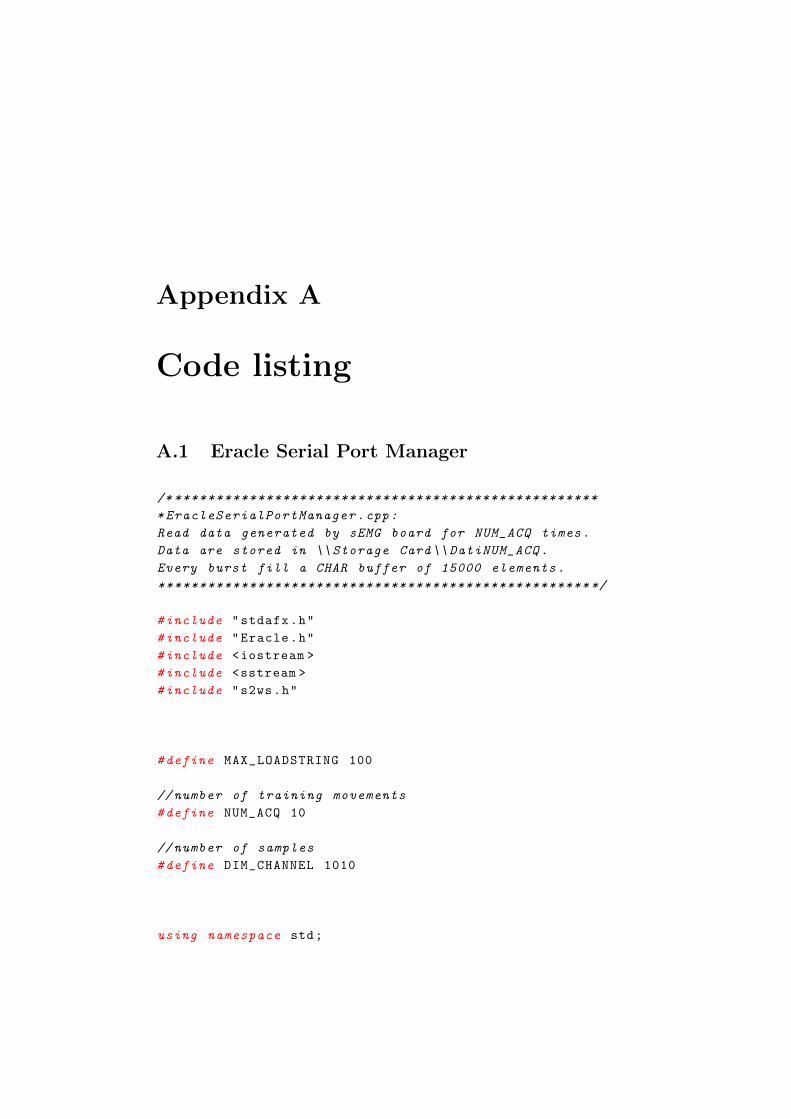
Appendix A
Code listing
A.1 Eracle Serial Port Manager
/* ***************************************************
*EracleSerialPortManager.cpp:
Read data generated by sEMG board for NUM_ACQ times.
Data are stored in \\ Storage Card\\ DatiNUM_ACQ.
Every burst fill a CHAR buffer of 15000 elements.
**************************************************** */
#include "stdafx.h"
#include "Eracle.h"
#include <iostream >
#include <sstream >
#include "s2ws.h"
#define MAX_LOADSTRING 100
// number of training movements
#define NUM_ACQ 10
// number of samples
#define DIM_CHANNEL 1010
using namespace std;
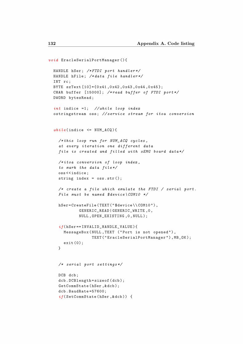
132 Appendix A. Code listing
void EracleSerialPortManager ()
HANDLE hSer; /*FTDI port handler */
HANDLE hFile; /*data file handler */
INT rc;
BYTE szText [10]=0x41 ,0x42 ,0x43 ,0x44 ,0x45;
CHAR buffer [15000]; /*read buffer of FTDI port*/
DWORD bytesRead;
int indice =1; // while loop index
ostringstream oss; // service stream for itoa conversion
while(indice <= NUM_ACQ )
/*this loop run for NUM_ACQ cycles ,
at every iteration one different data
file is created and filled with sEMG board data*/
/*itoa conversion of loop index ,
to mark the data file*/
oss <<indice;
string index = oss.str ();
/* create a file which emulate the FTDI / serial port.
File must be named $device\COM10 */
hSer=CreateFile(TEXT("$device \\ COM10"),
GENERIC_READ|GENERIC_WRITE ,0,
NULL ,OPEN_EXISTING ,0,NULL);
if(hSer== INVALID_HANDLE_VALUE )
MessageBox(NULL ,TEXT ("Port is not opened"),
TEXT("EracleSerialPortManager"),MB_OK);
exit (0);
/* serial port settings */
DCB dcb;
dcb.DCBlength=sizeof(dcb);
GetCommState(hSer ,&dcb);
dcb.BaudRate =57600;
if(SetCommState(hSer ,&dcb))
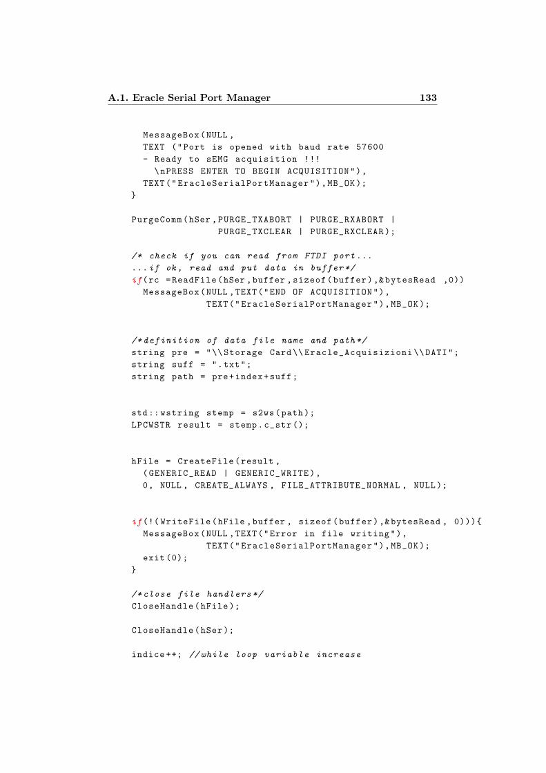
A.1. Eracle Serial Port Manager 133
MessageBox(NULL ,
TEXT ("Port is opened with baud rate 57600
- Ready to sEMG acquisition !!!
\nPRESS ENTER TO BEGIN ACQUISITION"),
TEXT("EracleSerialPortManager"),MB_OK);
PurgeComm(hSer ,PURGE_TXABORT | PURGE_RXABORT |
PURGE_TXCLEAR | PURGE_RXCLEAR );
/* check if you can read from FTDI port ...
...if ok , read and put data in buffer */
if(rc =ReadFile(hSer ,buffer ,sizeof(buffer),&bytesRead ,0))
MessageBox(NULL ,TEXT("END OF ACQUISITION"),
TEXT("EracleSerialPortManager"),MB_OK);
/* definition of data file name and path*/
string pre = "\\ Storage Card\\ Eracle_Acquisizioni \\DATI";
string suff = ".txt";
string path = pre+index+suff;
std:: wstring stemp = s2ws(path);
LPCWSTR result = stemp.c_str ();
hFile = CreateFile(result ,
(GENERIC_READ | GENERIC_WRITE),
0, NULL , CREATE_ALWAYS , FILE_ATTRIBUTE_NORMAL , NULL);
if(!( WriteFile(hFile ,buffer , sizeof(buffer),&bytesRead , 0)))
MessageBox(NULL ,TEXT("Error in file writing"),
TEXT("EracleSerialPortManager"),MB_OK);
exit (0);
/*close file handlers */
CloseHandle(hFile );
CloseHandle(hSer);
indice ++; // while loop variable increase

134 Appendix A. Code listing
// service stream flush
oss.str("");
oss.clear ();
MessageBox(NULL ,TEXT("End of acquisition procedure"),
TEXT("EracleSerialPortManager"),MB_OK);
return;
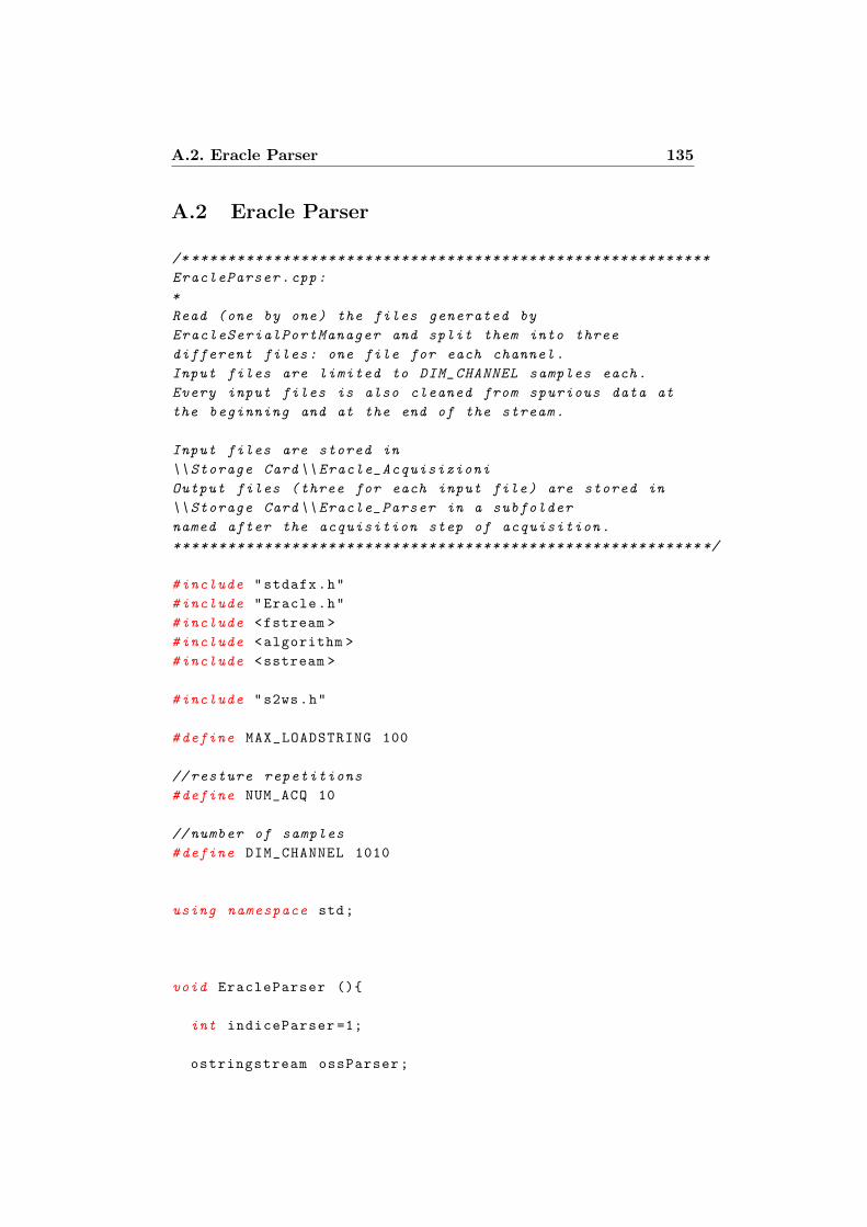
A.2. Eracle Parser 135
A.2 Eracle Parser
/* *********************************************************
EracleParser.cpp:
*
Read (one by one) the files generated by
EracleSerialPortManager and split them into three
different files: one file for each channel.
Input files are limited to DIM_CHANNEL samples each.
Every input files is also cleaned from spurious data at
the beginning and at the end of the stream.
Input files are stored in
\\ Storage Card\\ Eracle_Acquisizioni
Output files (three for each input file) are stored in
\\ Storage Card\\ Eracle_Parser in a subfolder
named after the acquisition step of acquisition.
********************************************************** */
#include "stdafx.h"
#include "Eracle.h"
#include <fstream >
#include <algorithm >
#include <sstream >
#include "s2ws.h"
#define MAX_LOADSTRING 100
// resture repetitions
#define NUM_ACQ 10
// number of samples
#define DIM_CHANNEL 1010
using namespace std;
void EracleParser ()
int indiceParser =1;
ostringstream ossParser;
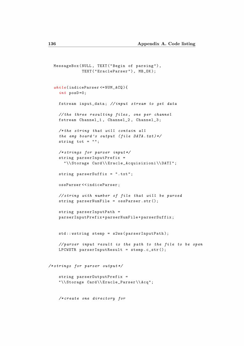
136 Appendix A. Code listing
MessageBox(NULL , TEXT("Begin of parsing"),
TEXT("EracleParser"), MB_OK);
while(indiceParser <= NUM_ACQ )
int posD =0;
fstream input_data; //input stream to get data
//the three resulting files , one per channel
fstream Channel_1 , Channel_2 , Channel_3;
/*the string that will contain all
the emg board’s output (file DATA.txt)*/
string tot = "";
/* strings for parser input*/
string parserInputPrefix =
"\\ Storage Card\\ Eracle_Acquisizioni \\DATI";
string parserSuffix = ".txt";
ossParser <<indiceParser;
// string with number of file that will be parsed
string parserNumFile = ossParser.str ();
string parserInputPath =
parserInputPrefix+parserNumFile+parserSuffix;
std:: wstring stemp = s2ws(parserInputPath );
// parser input result is the path to the file to be open
LPCWSTR parserInputResult = stemp.c_str ();
/* strings for parser output */
string parserOutputPrefix =
"\\ Storage Card\\ Eracle_Parser \\Acq";
/* create one directory for
A.2. Eracle Parser 137
each acquisition in folder Eracle_Parser */
string parserOutFolder =
parserOutputPrefix+parserNumFile;
std:: wstring stemp1 = s2ws(parserOutFolder );
LPCWSTR parserFolderResult = stemp1.c_str ();
CreateDirectory(parserFolderResult ,NULL);
string parserFileOutput1 = "\\ Channel_1.txt";
string parserFileOutput2 = "\\ Channel_2.txt";
string parserFileOutput3 = "\\ Channel_3.txt";
string parserPathOutput1 = parserOutFolder+
parserFileOutput1;
string parserPathOutput2 = parserOutFolder+
parserFileOutput2;
string parserPathOutput3 = parserOutFolder+
parserFileOutput3;
std:: wstring stemp_uno = s2ws(parserPathOutput1 );
std:: wstring stemp_due = s2ws(parserPathOutput2 );
std:: wstring stemp_tre = s2ws(parserPathOutput3 );
LPCWSTR parserOutPath1Result = stemp_uno.c_str ();
LPCWSTR parserOutPath2Result = stemp_due.c_str ();
LPCWSTR parserOutPath3Result = stemp_tre.c_str ();
//open stream to read data file
input_data.open(parserInputResult , fstream ::in);
//open stream to the three output files
Channel_1.open(parserOutPath1Result ,fstream ::out);
Channel_2.open(parserOutPath2Result ,fstream ::out);
Channel_3.open(parserOutPath3Result ,fstream ::out);
/*check for file opening error*/
if (( input_data.fail ())||( Channel_1.fail ())||
(Channel_2.fail ())||( input_data.fail ())||
138 Appendix A. Code listing
(Channel_3.fail ()))
MessageBox(NULL ,TEXT ("Error in opening files"),
TEXT("EracleParser"),MB_OK);
exit (0);
/*read all the data in input stream and
store them in string tot*/
while(input_data.good ())
getline(input_data ,tot);
/* ****************************************
BEGIN OF PARSING *************************
**************************************** */
/* (((1))) replace newline and carriage return with spaces */
replace(tot.begin(), tot.end(), ’\r’, ’ ’);
replace(tot.begin(), tot.end(), ’\n’, ’ ’);
/* (((2))) find and erase spurious
input vector at the begin of data*/
posD=tot.find("D"); //find the position of the first D
if(posD !=0) //if file doesn ’t begin with D...
tot.erase(0,posD); //... erase alla charachters before D
/* (((3))) delete the last input vector ,
to prevent spurious data at the end of stream */
size_t ultimo;
A.2. Eracle Parser 139
size_t fine;
//get the position of last D...
ultimo = tot.rfind("D");
//... and the position of the termination char
fine = tot.rfind("\0");
// delete last row , but don’t erase "\0" charachter
tot.erase(ultimo , fine -1);
/* (((4))) count the number of D
--> this is also the number of rows
--> this is also the number of "good" data acquired */
// numbers of "clean" data acquired
int conteggio = count(tot.begin(),tot.end(),’D’);
if(conteggio <DIM_CHANNEL )
MessageBox(NULL , TEXT("Pochi campioni"),
TEXT("EracleParser"), MB_OK);
exit (0);
/* (((5))) split string tot in three files ,
each column to a file , each data separated
by a blank spaces (included the last one)*/
size_t begin ,end;
//get the indeces of the first number in first row
begin = tot.find("D");
end = tot.find(" ");
int index;
int row_count =0;
//run until 1010 lines have been parsed
while(row_count < DIM_CHANNEL )
140 Appendix A. Code listing
/*for the first number indeces
have already been acquired */
if(row_count >0)
begin = tot.find("D",end);
end = tot.find(" ",begin +1);
//first number of the triple --> to file Channel_1
for(index = static_cast <int >(begin )+2;
index <static_cast <int >(end); index ++)
Channel_1 <<tot[index];
Channel_1 <<" ";
// adjust indeces
begin = tot.find(" ",end);
end = tot.find(" ",begin +1);
// second number of the triple --> to file Channel_2
for(index = static_cast <int >(begin )+1;
index <static_cast <int >(end); index ++)
Channel_2 <<tot[index];
Channel_2 <<" ";
// adjust indeces
begin = tot.find(" ",end);
end = tot.find(" ",begin +1);
//last number of the triple --> to file Channel_3
for(index = static_cast <int >(begin )+1;
index <static_cast <int >(end); index ++)
Channel_3 <<tot[index];
Channel_3 <<" ";
row_count ++;
/*close all streams */
Channel_1.close ();
Channel_2.close ();
A.2. Eracle Parser 141
Channel_3.close ();
input_data.close ();
// parsingCheck(conteggio );
//clear the itoa buffer
ossParser.str("");
ossParser.clear ();
indiceParser ++; //loop variable ++
MessageBox(NULL ,TEXT ("End of Parsing"),
TEXT("eracleParser"),MB_OK);
return;
142 Appendix A. Code listing
A.3 Eracle FastICA
/* ******************************************************
EracleFastICA.cpp:
*
Open the files previously generated by the parser and:
- compute and subtract the average value of
each channel (remmean );
- compute the unmixing matrix;
- apply FastICA algorithm;
- Add the mean back to the data.
In the output result of ICA are corrected with
a mean calculation inspired from
MATLAB implementation of FastICA.
The output vectors are stored in three separated files
in Eracle_FastICA: three files for
each sampling (one per channel ).
******************************************************* */
#include "stdafx.h"
#include "Eracle.h"
#include <iostream >
#include <string >
#include <fstream >
#include <sstream >
#include "ltiVector.h"
#include "ltiMatrix.h"
#include "ltiFastICA.h"
#include "s2ws.h"
using namespace std;
#define MAX_LOADSTRING 100
// number of gesture repetitions
#define NUM_ACQ 10
// number of samples
#define DIM_CHANNEL 1010
void EracleFastICA ()
A.3. Eracle FastICA 143
MessageBox(NULL , TEXT("Begin of FastICA"),
TEXT("EracleFastICA"), MB_OK);
// variables for loop control and itoa conversion
int indiceICA = 1;
ostringstream ossICA;
while(indiceICA <= NUM_ACQ )
// stream for summary operations
fstream fastica_stream;
/*input files; one for each channel ,
these files are produced
by EracleParser () function */
FILE * Mazinga1;
FILE * Mazinga2;
FILE * Mazinga3;
// FastICA path string input building
string ICAInputfolderPrefix =
"\\ Storage Card\\ Eracle_Parser \\Acq";
ossICA <<indiceICA;
string ICANumFile = ossICA.str ();
string ICAinput1 = "\\ Channel_1.txt";
string ICAinput2 = "\\ Channel_2.txt";
string ICAinput3 = "\\ Channel_3.txt";
string ICAInputfile1Path = ICAInputfolderPrefix +
ICANumFile + ICAinput1;
string ICAInputfile2Path = ICAInputfolderPrefix +
ICANumFile + ICAinput2;
string ICAInputfile3Path = ICAInputfolderPrefix +
ICANumFile + ICAinput3;
/*it is not necessary to convert string to wstring ,
as fopen uses const char * to open file.
String can be converted to const
144 Appendix A. Code listing
char * using data() method */
// output folder creation
string ICAOutputfolderPrefix =
"\\ Storage Card\\ Eracle_FastICA \\Acq";
string ICAOutputFolder = ICAOutputfolderPrefix
+ ICANumFile;
std:: wstring ICAtemp0 = s2ws(ICAOutputFolder );
LPCWSTR ICAFolderResult = ICAtemp0.c_str ();
CreateDirectory(ICAFolderResult ,NULL);
// summary filestream string path
string ICAOutputSuffix = "\\ FastICA.txt";
string ICAOutputSummary = ICAOutputFolder
+ ICAOutputSuffix;
std:: wstring ICAtemp = s2ws(ICAOutputSummary );
LPCWSTR ICASummaryResult = ICAtemp.c_str ();
// Perform file and stream opening and check for errors
//open summary filestream
fastica_stream.open(ICASummaryResult , fstream ::out);
/*check for stream opening error*/
if (fastica_stream.fail ())
MessageBox(NULL ,TEXT ("Error in opening filestream"),
TEXT("EracleFastICA"),MB_OK);
PostQuitMessage (0);
Mazinga1=fopen (ICAInputfile1Path.data(),"r");
Mazinga2=fopen (ICAInputfile2Path.data(),"r");
Mazinga3=fopen (ICAInputfile3Path.data(),"r");
if (( Mazinga1 ==NULL )||
(Mazinga2 ==NULL )||

A.3. Eracle FastICA 145
(Mazinga3 ==NULL)) /* check for files opening error*/
MessageBox(NULL ,TEXT ("Error in opening input files"),
TEXT("EracleFastICA"),MB_OK);
exit (0);
/*data array declarations - one per channel
- and the "global" array tot*/
double ch1_data[DIM_CHANNEL ];
double ch2_data[DIM_CHANNEL ];
double ch3_data[DIM_CHANNEL ];
double tot[DIM_CHANNEL *3];
//copy data from files to vectors
for(int k=0;k<DIM_CHANNEL;k++)
fscanf(Mazinga1 , "%lf", &ch1_data[k]);
fscanf(Mazinga2 , "%lf", &ch2_data[k]);
fscanf(Mazinga3 , "%lf", &ch3_data[k]);
/*check equal and fixed number of data acquired ,
exit if different */
if(( sizeof(ch1_data )/ sizeof(double )!= DIM_CHANNEL )||
(sizeof(ch2_data )/ sizeof(double )!= DIM_CHANNEL )||
(sizeof(ch3_data )/ sizeof(double )!= DIM_CHANNEL ))
MessageBox(NULL ,TEXT ("Array size error"),
TEXT("EracleFastICA"),MB_OK);
exit (0);
//fill the tot vector
int i;
for(i=0;i<DIM_CHANNEL;i++)
tot[i]= ch1_data[i];
146 Appendix A. Code listing
for(i=DIM_CHANNEL;i<DIM_CHANNEL *2;i++)
tot[i]= ch2_data[i-DIM_CHANNEL ];
for(i=DIM_CHANNEL *2;i<DIM_CHANNEL *3;i++)
tot[i]= ch3_data[i-DIM_CHANNEL *2];
/* matrix constructor: 3 rows (one per source)
and DIM_CHANNEL columns */
lti::matrix <double > source(3,DIM_CHANNEL ,tot),W,clean;
//for fastICA rows and cols must be transposed:
/*after transpose
each ROW is an acquisition(input vector),
so it contains one sample for each source
each COL is the set of data acquired by a
single channel
CH1 CH2 CH3
iV1 | | |
iV2 | | |
. | | | -->>> this is sourceT !!!
. | | |
. | | |
*/
lti::matrix <double > sourceT;
sourceT.transpose(source );
// +++++++++++++++++++++++++++++++++++++++++++++++++++++
//*REMMEAN:
// compute the mean of each channel (column) and subtract
//it from the data
// before passing them to fastica */
double mean [3];
double temporale =0;
for(int j=0;j<3;j++)
A.3. Eracle FastICA 147
for(int i=0; i<DIM_CHANNEL; i++)
temporale = temporale+sourceT.at(i,j);
mean[j]= temporale/DIM_CHANNEL;
temporale = 0;
lti::matrix <double > media(1,3,mean);
const double init =1;
lti::matrix <double > ones(DIM_CHANNEL ,1,init);
lti::matrix <double > matmedia;
matmedia.multiply(ones ,media );
sourceT.subtract(matmedia );
// +++++++++++++++++++++++++++++++++++++++++++++++++
lti::fastICA <double > pippo;
lti:: matrix <double > constTransfMatrix;
pippo.apply(sourceT ,clean );
pippo.getTransformMatrix(constTransfMatrix );
lti::vector <double > vec;
pippo.getOffsetVector(vec);
/* ***********************************************
mean correction of FastICA output
(inspired by MATLAB FastICA package)
uscita = W * unmixedsig + (W * mixedmean)
* ones (1, NumOfSampl );
************************************************ */
148 Appendix A. Code listing
lti::matrix <double > primoMembro;
/* primoMembro = W*unmixedsig
unmixedsig is FastICA output ,
it must be transposed in cleanT to be multiplied */
lti::matrix <double > cleanT;
cleanT.transpose(clean);
primoMembro.multiply(constTransfMatrix ,cleanT );
/*v=W*mixedmean:
before multiply b v contains the mean of
the input data (mixedmean );
after multilply b is the result of the operation */
lti::vector <double > v;
pippo.getOffsetVector(v);
constTransfMatrix.multiply(v);
/*v must be transposed to compute
the last multiply
(but there ’s no tranpose method
for vectors in LTILIB)*/
double appoggio [3];
for(int h=0;h<3;h++) //"homemade" transpose
appoggio[h]=v.at(h);
/*as in LTILIB doesn’t exists a column vector ,
a 3x1 matrix is used
appoggioMatrice = (W * mixedmean)*/
lti::matrix <double > appoggioMatrice (3,1, appoggio );
/*a matrix full of ones , in MATLAB it would be:
unii=ones(1, DIM_CHANNEL)*/
const double inival =1;
A.3. Eracle FastICA 149
lti::matrix <double > unii(1,DIM_CHANNEL ,inival );
// secondoMembro = appoggioMatrice*unii
lti::matrix <double > secondoMembro;
secondoMembro.multiply(appoggioMatrice ,unii);
// uscita = primoMembro + secondoMembro
lti::matrix <double > uscita ,uscitaT;
uscita = primoMembro+secondoMembro;
// transposing matrix uscita , just for reading purpose
uscitaT.transpose(uscita );
/* ******************************************************* */
// FastICA output file path string building
string IcaOutput1 = "\\ Clean1_ICA.txt";
string IcaOutput2 = "\\ Clean2_ICA.txt";
string IcaOutput3 = "\\ Clean3_ICA.txt";
string ICAInputFile1Path = ICAOutputFolder
+ IcaOutput1;
string ICAInputFile2Path = ICAOutputFolder
+ IcaOutput2;
string ICAInputFile3Path = ICAOutputFolder
+ IcaOutput3;
std:: wstring ICAtemp1 = s2ws(ICAInputFile1Path );
std:: wstring ICAtemp2 = s2ws(ICAInputFile2Path );
std:: wstring ICAtemp3 = s2ws(ICAInputFile3Path );
LPCWSTR ICAInputFile1Result = ICAtemp1.c_str ();
LPCWSTR ICAInputFile2Result = ICAtemp2.c_str ();
LPCWSTR ICAInputFile3Result = ICAtemp3.c_str ();
//files for EracleFastICA output
fstream clean1 ,clean2 ,clean3;
150 Appendix A. Code listing
clean1.open(ICAInputFile1Result ,fstream ::out);
clean2.open(ICAInputFile2Result ,fstream ::out);
clean3.open(ICAInputFile3Result ,fstream ::out);
//check for opening file errors
if(( clean1.fail ())||( clean2.fail ())||( clean3.fail ()))
MessageBox(NULL ,TEXT ("Error in opening OUTPUT file"),
TEXT("EracleFastICA"),MB_OK);
/*split the clean matrix in 3 different file ,
that will be opened by EracleRMS ,
each sample is separated by a white space.
If input matrix is uscitaT -->>>>
the "mean corrected" values are printed
If input matrix is clean -->>>>
the raw values returned by apply are printed */
for(int r=0; r<DIM_CHANNEL; r++)
clean1 <<uscitaT.at(r,0);
clean1 <<" ";
clean2 <<uscitaT.at(r,1);
clean2 <<" ";
clean3 <<uscitaT.at(r,2);
clean3 <<" ";
/*close files and streams */
clean1.close ();
clean2.close ();
clean3.close ();
fastica_stream.close ();
fclose(Mazinga1 );
fclose(Mazinga2 );
fclose(Mazinga3 );
//flush of ostringstream
ossICA.str("");
ossICA.clear ();
A.3. Eracle FastICA 151
indiceICA ++; //loop variable ++
pippo .~ fastICA ();
constTransfMatrix .~ matrix ();
sourceT .~ matrix ();
source .~ matrix ();
cleanT .~ matrix ();
clean .~ matrix ();
uscita .~ matrix ();
uscitaT .~ matrix ();
MessageBox(NULL , TEXT("End of FastICA"),
TEXT("EracleFastICA"), MB_OK);
return;
152 Appendix A. Code listing
A.4 Eracle RMS
/* ******************************************************
EracleRMS.cpp:
*
For each acquisition opens the the three output files
generated by FastICAand compute RMS for each of them.
At the end of run there are 3* NUM_ACQ values of RMS
stored in file RMS.txt in Eracle_RMS.
These values will be used to train the NN.
******************************************************* */
#include "stdafx.h"
#include "Eracle.h"
#include <iostream >
#include <string >
#include <fstream >
#include <sstream >
#include "ltiMatrix.h"
#include "s2ws.h"
using namespace std;
#define MAX_LOADSTRING 100
// movement repetitions
#define NUM_ACQ 10
// number of sampled data
#define DIM_CHANNEL 1010
void EracleRMS ()
MessageBox(NULL , TEXT("Begin of RMS"),
TEXT("EracleRMS"), MB_OK);
int indiceRMS = 1;
ostringstream ossRMS;
// output filestream
A.4. Eracle RMS 153
fstream RootMeanSquare;
RootMeanSquare.open(
"\\ Storage Card\\ Eracle_RMS \\RMS.txt",
fstream ::out);
while(indiceRMS <= NUM_ACQ )
/*open files created by fastICA ,
read the formatted value (double)
and fill a matrix ,
one column for each channel */
string RMSInputPrefix =
"\\ Storage Card\\ Eracle_FastICA \\Acq";
ossRMS <<indiceRMS;
string RMSNumFile = ossRMS.str ();
string RMSInput1 = "\\ Clean1_ICA.txt";
string RMSInput2 = "\\ Clean2_ICA.txt";
string RMSInput3 = "\\ Clean3_ICA.txt";
string RMSInput1Path = RMSInputPrefix +
RMSNumFile + RMSInput1;
string RMSInput2Path = RMSInputPrefix +
RMSNumFile + RMSInput2;
string RMSInput3Path = RMSInputPrefix +
RMSNumFile + RMSInput3;
FILE * source1;
FILE * source2;
FILE * source3;
source1=fopen (RMSInput1Path.data(),"r");
source2=fopen (RMSInput2Path.data(),"r");
source3=fopen (RMSInput3Path.data(),"r");
/*check for files opening error*/
if (( source1 ==NULL )||
(source2 ==NULL )||
(source3 ==NULL )||
(RootMeanSquare.fail ()))
MessageBox(NULL ,TEXT ("Error in opening input files"),
TEXT("EracleRMS"),MB_OK);
154 Appendix A. Code listing
/*one array for each source ,
and a global vector that will
be use to fill the matrix */
double source1_data[DIM_CHANNEL ];
double source2_data[DIM_CHANNEL ];
double source3_data[DIM_CHANNEL ];
double source_tot[DIM_CHANNEL *3];
//copy data from files to vectors
for(int k=0;k<DIM_CHANNEL;k++)
fscanf(source1 , "%lf", &source1_data[k]);
fscanf(source2 , "%lf", &source2_data[k]);
fscanf(source3 , "%lf", &source3_data[k]);
/*check equal and fixed number
of data acquired , exit if different */
if( (sizeof(source1_data )/ sizeof(double )!= DIM_CHANNEL )||
(sizeof(source2_data )/ sizeof(double )!= DIM_CHANNEL )||
(sizeof(source3_data )/ sizeof(double )!= DIM_CHANNEL ))
MessageBox(NULL ,TEXT ("Array size error"),
TEXT("EracleRMS"),MB_OK);
exit (0);
//fill the global vector
int i;
for(i=0;i<DIM_CHANNEL;i++)
source_tot[i]= source1_data[i];
for(i=DIM_CHANNEL;i<DIM_CHANNEL *2;i++)
source_tot[i]= source2_data[i-DIM_CHANNEL ];
A.4. Eracle RMS 155
for(i=DIM_CHANNEL *2;i<DIM_CHANNEL *3;i++)
source_tot[i]= source3_data[i-DIM_CHANNEL *2];
/* matrix creation: 3 rows (one per source)
and DIM_CHANNEL column */
lti::matrix <double > clean_source (3,DIM_CHANNEL ,
source_tot );
/*apply the formula:
sqrt ((1/ DIM_CHANNEL )*SUM(i=0,i=DIM_CHANNEL )[Si^2])
for each column of the matrix
generated by EracleFastICA function.
The value of RMS are stored in a file ,
separated by a blank spaces */
double RMS;
double sumOfSquare =0;
for(int ch=0; ch <3;ch++)
for(int k=0;k<DIM_CHANNEL;k++)
sumOfSquare=sumOfSquare+
pow(clean_source.at(ch ,k),2);
RMS = sqrt(sumOfSquare/DIM_CHANNEL );
RootMeanSquare <<RMS *100;
RootMeanSquare <<" ";
RMS =0;
sumOfSquare =0;
156 Appendix A. Code listing
fclose(source1 );
fclose(source2 );
fclose(source3 );
//flush of ostringstream
ossRMS.str("");
ossRMS.clear ();
indiceRMS ++; //loop variable ++
RootMeanSquare.close ();
MessageBox(NULL ,TEXT ("End of RMS calculation"),
TEXT("EracleRMS"),MB_OK);
return;
A.5. Eracle Neural Network Train 157
A.5 Eracle Neural Network Train
/* *******************************************************
EracleNeuralNetworkTRAIN.cpp:
*
Open the (number of movement , actually 6)
files in Eracle_NN
containing each NUM_ACQ *3 root mean square.
These values are employed to train an Artificial
Neural Network that will
be used to recognize the user’s movement.
The NN is saved in EracleNN in TrainedNN.dat
******************************************************* */
#include "stdafx.h"
#include "Eracle.h"
#include <iostream >
#include <string >
#include <fstream >
#include <sstream >
#include <ltiMLP.h>
#include <ltiLispStreamHandler.h>
#include "ltiRbf.h"
using namespace std;
#define MAX_LOADSTRING 100
// number of repetitions
#define NUM_ACQ 10
// number of samples
#define DIM_CHANNEL 1010
void EracleNeuralNetworkTRAIN ()
fstream nnTrain;
nnTrain.open("\\ Storage Card\\ Eracle_NN \\ nnTrain.txt",
fstream ::out);
/* (((1)))
open the 6 files with the movement RMS:*/
FILE* mov0;
158 Appendix A. Code listing
FILE* mov1;
FILE* mov2;
FILE* mov3;
FILE* mov4;
mov0=fopen("\\ Storage card\\ Eracle_NN
\\ RMSmov0.txt","r");
mov1=fopen("\\ Storage card\\ Eracle_NN
\\ RMSmov1.txt","r");
mov2=fopen("\\ Storage card\\ Eracle_NN
\\ RMSmov2.txt","r");
mov3=fopen("\\ Storage card\\ Eracle_NN
\\ RMSmov3.txt","r");
mov4=fopen("\\ Storage card\\ Eracle_NN
\\ RMSmov4.txt","r");
/* (((2)))
fill the global array reading from each file*/
// examples data array for training
double RMSglobal [(( NUM_ACQ )*3)*5];
// answer data array for training
int RMSanswer [NUM_ACQ *5];
//fill each input vector with data from corresponding file
//(( NUM_ACQ )*3) RMS for mov0
for(int k=0;k<(( NUM_ACQ )*3);k++)
fscanf(mov0 , "%lf", &RMSglobal[k]);
//(( NUM_ACQ )*3) RMS for mov1
for(int k=(( NUM_ACQ )*3);k<((( NUM_ACQ )*3)*2);k++)
fscanf(mov1 , "%lf", &RMSglobal[k]);
//(( NUM_ACQ )*3) RMS for mov2
for(int k=((( NUM_ACQ )*3)*2);k<((( NUM_ACQ )*3)*3);k++)
fscanf(mov2 , "%lf", &RMSglobal[k]);
A.5. Eracle Neural Network Train 159
//(( NUM_ACQ )*3) RMS for mov3
for(int k=((( NUM_ACQ )*3)*3);k<((( NUM_ACQ )*3)*4);k++)
fscanf(mov3 , "%lf", &RMSglobal[k]);
//(( NUM_ACQ )*3) RMS for mov4
for(int k=((( NUM_ACQ )*3)*4);k<((( NUM_ACQ )*3)*5);k++)
fscanf(mov4 , "%lf", &RMSglobal[k]);
// examples matrix for training
lti:: dmatrix train_matrix (5* NUM_ACQ ,3, RMSglobal );
//fill the answer training vector
int i;
// NUM_ACQ rms represent mov0
for(i=0; i<NUM_ACQ; i++)
RMSanswer[i]=0;
// NUM_ACQ rms represent mov1
for(i = NUM_ACQ; i<NUM_ACQ *2;i++)
RMSanswer[i]=1;
// NUM_ACQ rms represent mov2
for(i = NUM_ACQ *2; i<NUM_ACQ *3;i++)
RMSanswer[i]=2;
// NUM_ACQ rms represent mov3
for(i = NUM_ACQ *3; i<NUM_ACQ *4;i++)
RMSanswer[i]=3;
// NUM_ACQ rms represent mov4
for(i = NUM_ACQ *4; i<NUM_ACQ *5;i++)
RMSanswer[i]=4;
// answer vector for training
lti:: ivector train_results_vector (NUM_ACQ*5, RMSanswer );
// object NN
lti::MLP ann;

160 Appendix A. Code listing
//NN parametersss
lti::MLP:: parameters param;
lti::MLP:: sigmoidFunctor sigmoid (1);
param.setLayers (12, sigmoid );
param.trainingMode=lti::MLP:: parameters :: SteepestDescent;
param.maxNumberOfEpochs =2000;
param.learnrate =0.01;
//param.momentum =1.0;
//param.stopError =0.002;
ann.setParameters(param);
MessageBox(NULL ,TEXT("Begin of training"),
TEXT("EracleNeuralNetworkTRAIN"),MB_OK);
ann.train(train_matrix ,train_results_vector );
MessageBox(NULL ,TEXT("End of training"),
TEXT("EracleNeuralNetworkTRAIN"),MB_OK);
ofstream recNN ("\\ Storage Card\\ Eracle_NNu
\\ TrainedNN.dat");
lti:: lispStreamHandler lsh(recNN);
ann.write(lsh);
recNN.close ();
MessageBox(NULL ,TEXT("Trained NN saved"),
TEXT("EracleNeuralNetworkTRAIN"),MB_OK);
fclose(mov0);
fclose(mov1);
fclose(mov2);
fclose(mov3);
fclose(mov4);
// fclose(mov5);
return;
A.6. Eracle Neural Network Classify 161
A.6 Eracle Neural Network Classify
/* *********************************************************
EracleRecognizer.cpp:
*
read the previous data acquired corresponding to a
single movement to be classified.
Data are splitted in three files: Parser_Ch1.txt ,
Parser_Ch2.txt , Parser_Ch3.txt.
Then they are computed by fastica , the unmix matrix is
computed and directly used in fastica processing.
Fastica output vectors are used to calculate rms of the
input movement , then they are passed to the prevoiusly
trained NN , which classify the movement performed.
The ouput rms and the nn answer are saved in Rec.txt.
All handled files are stored in
\\ Storage Card\\ Eracle_Recognizer
********************************************************* */
#include "stdafx.h"
#include "s2ws.h"
#include <fstream >
#include "ltiVector.h"
#include "ltiMatrix.h"
#include "ltiFastICA.h"
#include <ltiMLP.h>
#include <ltiLispStreamHandler.h>
#include "ltiRbf.h"
#define MAX_LOADSTRING 100
#define DIM_CHANNEL 1010
using namespace std;
// variable for result index
int id;
void EracleRecognizer ()
162 Appendix A. Code listing
/*file stream for global function output */
fstream recognizer;
recognizer.open("\\ Storage Card\\ Eracle_Recognizer
\\Rec.txt",fstream ::out);
if(recognizer.fail ())
MessageBox(NULL , TEXT("Error in opening output file"),
TEXT("eracleParser"), MB_OK);
exit (0);
/* (((1))) Data parser ************************************** */
int posD =0;
fstream Channel_1 , Channel_2 , Channel_3;
Channel_1.open("\\ Storage Card\\ Eracle_Recognizer
\\ Parser_Ch1.txt",fstream ::out);
Channel_2.open("\\ Storage Card\\ Eracle_Recognizer
\\ Parser_Ch2.txt",fstream ::out);
Channel_3.open("\\ Storage Card\\ Eracle_Recognizer
\\ Parser_Ch3.txt",fstream ::out);
if(Channel_1.fail ()|| Channel_2.fail ()|| Channel_3.fail ())
MessageBox(NULL , TEXT("Error in opening parser output file"),
TEXT("eracleParser"), MB_OK);
exit (0);
//input stream to get data
fstream input_data;
/*the string that will contain all the emg
board ’s output (file DATA.txt)*/
string tot = "";
//open stream to read data file
input_data.open("\\ Storage Card\\ Eracle_Recognizer
\\DATI.txt", fstream ::in);
if(input_data.fail ())
MessageBox(NULL , TEXT("Error in opening data input file"),
TEXT("eracleParser"), MB_OK);
exit (0);
A.6. Eracle Neural Network Classify 163
/*read all the data in input stream
and store them in string tot*/
while(input_data.good ())
getline(input_data ,tot);
/* ****************************************
BEGIN OF PARSING *************************
**************************************** */
/* (((1))) replace newline and carriage return with spaces */
replace(tot.begin(), tot.end(), ’\r’, ’ ’);
replace(tot.begin(), tot.end(), ’\n’, ’ ’);
/* (((2))) find and erase spurious input
vector at the begin of data*/
//find the position of the first D
posD=tot.find("D");
//if file doesn’t begin with D...
if(posD !=0)
//... erase alla charachters before D
tot.erase(0,posD);
/* (((3))) delete the last input vector , to prevent
spurious data at the end of stream */
size_t ultimo;
size_t fine;
//get the position of last D...
164 Appendix A. Code listing
ultimo = tot.rfind("D");
//... and the position of the terminator
fine = tot.rfind("\0");
// delete last row , but don’t erase "\0" charachter
tot.erase(ultimo , fine -1);
/* (((4))) count the number of D
--> this is also the number of rows
--> this is also the number of "good" data acquired */
// numbers of "clean" data acquired
int conteggio = count(tot.begin(),tot.end(),’D’);
if(conteggio <1010)
MessageBox(NULL , TEXT("Pochi campioni"),
TEXT("eracleParser"), MB_OK);
exit (0);
/* (((5))) split string tot in three files ,
each column to a file , each data separated
by a blank spaces (included the last one)*/
size_t begin ,end;
//get the indeces of the first number in first row
begin = tot.find("D");
end = tot.find(" ");
int index;
int row_count =0;
//run until 1010 lines have been parsed
while(row_count < DIM_CHANNEL )
//for the first number indeces have already been acquired
if(row_count >0)
begin = tot.find("D",end);
A.6. Eracle Neural Network Classify 165
end = tot.find(" ",begin +1);
//first number of the triple --> to file Channel_1
for( index = static_cast <int >( begin )+2;
index <static_cast <int >(end); index ++)
Channel_1 <<tot[index];
Channel_1 <<" ";
// adjust indeces
begin = tot.find(" ",end);
end = tot.find(" ",begin +1);
// second number of the triple --> to file Channel_2
for(index = static_cast <int >(begin )+1;
index <static_cast <int >(end); index ++)
Channel_2 <<tot[index];
Channel_2 <<" ";
// adjust indeces
begin = tot.find(" ",end);
end = tot.find(" ",begin +1);
//last number of the triple --> to file Channel_3
for(index = static_cast <int >(begin )+1;
index <static_cast <int >(end); index ++)
Channel_3 <<tot[index];
Channel_3 <<" ";
row_count ++;
/*close all streams */
input_data.close ();
Channel_1.close ();
Channel_2.close ();
Channel_3.close ();
166 Appendix A. Code listing
/* (((2))) FASTICA *************************************** */
/*unmix matrix is computed on the (unique) movement
acquired and it is applied to the same set of data*/
lti:: matrix <double > constTransfMatrix;
lti::fastICA <double > pippo;
fstream fastica_stream; // stream for summary operations
/*input files; one for each channel ,
these files are produced by EracleParser () function */
FILE * Mazinga1;
FILE * Mazinga2;
FILE * Mazinga3;
//open summary filestream
fastica_stream.open("\\ Storage Card\\ Eracle_Recognizer
\\ FastICA.txt", fstream ::out);
/*check for stream opening error*/
if (fastica_stream.fail ())
MessageBox(NULL ,TEXT ("Error in opening filestream"),
TEXT("EracleFastICA"),MB_OK);
exit (0);
Mazinga1=fopen ("\\ Storage Card\\ Eracle_Recognizer
\\ Parser_Ch1.txt","r");
Mazinga2=fopen ("\\ Storage Card\\ Eracle_Recognizer
\\ Parser_Ch2.txt","r");
Mazinga3=fopen ("\\ Storage Card\\ Eracle_Recognizer
\\ Parser_Ch3.txt","r");
if (( Mazinga1 ==NULL )||
(Mazinga2 ==NULL )||
(Mazinga3 ==NULL)) /* check for files opening error*/
MessageBox(NULL ,TEXT ("Error in opening Fastica input file"),
TEXT("EracleFastICA"),MB_OK);
exit (0);
A.6. Eracle Neural Network Classify 167
/*data array declarations -
one per channel - and the "global" array tot*/
double ch1_data[DIM_CHANNEL ];
double ch2_data[DIM_CHANNEL ];
double ch3_data[DIM_CHANNEL ];
double ICAtot[DIM_CHANNEL *3];
//copy data from files to vectors
for(int k=0;k<DIM_CHANNEL;k++)
fscanf(Mazinga1 , "%lf", &ch1_data[k]);
fscanf(Mazinga2 , "%lf", &ch2_data[k]);
fscanf(Mazinga3 , "%lf", &ch3_data[k]);
/*check equal and fixed number
of data acquired , exit if different */
if(( sizeof(ch1_data )/ sizeof(double )!= DIM_CHANNEL )||
(sizeof(ch2_data )/ sizeof(double )!= DIM_CHANNEL )||
(sizeof(ch3_data )/ sizeof(double )!= DIM_CHANNEL ))
MessageBox(NULL ,TEXT ("Array size error"),
TEXT("EracleFastICA"),MB_OK);
exit (0);
//fill the tot vector
int i;
for(i=0;i<DIM_CHANNEL;i++)
ICAtot[i]= ch1_data[i];
for(i=DIM_CHANNEL;i<DIM_CHANNEL *2;i++)
ICAtot[i]= ch2_data[i-DIM_CHANNEL ];
168 Appendix A. Code listing
for(i=DIM_CHANNEL *2;i<DIM_CHANNEL *3;i++)
ICAtot[i]= ch3_data[i-DIM_CHANNEL *2];
/* matrix creation: 3 rows (one per source)
and DIM_CHANNEL columns */
lti::matrix <double > source(3,DIM_CHANNEL ,ICAtot );
lti::matrixi <double > W,clean;
//for fastICA rows and cols must be transposed:
/*after transpose
each ROW is an acquisition(input vector),
so it contains one sample for each source
each COL is the set of data acquired
by a single channel
CH1 CH2 CH3
iV1 | | |
iV2 | | |
. | | |
. | | |
. | | |
*/
lti::matrix <double > sourceT;
sourceT.transpose(source );
// +++++++++++++++++++++++++++++++++++++++++++++++++++++++++++
//*REMMEAN:
// compute the mean of each channel (column)
//and subtract it from the data
// before passing them to fastica */
double mean [3];
double temporale =0;
for(int j=0;j<3;j++)
for(int i=0; i<DIM_CHANNEL; i++)
temporale = temporale+sourceT.at(i,j);

A.6. Eracle Neural Network Classify 169
mean[j]= temporale/DIM_CHANNEL;
temporale = 0;
lti::matrix <double > media(1,3,mean);
const double init =1;
lti::matrix <double > ones(DIM_CHANNEL ,1,init);
lti::matrix <double > matmedia;
matmedia.multiply(ones ,media );
sourceT.subtract(matmedia );
// +++++++++++++++++++++++++++++++++++++++++++++++++++++++++++++
/* getOffsetVector returns the mean
of each channel of the input data*/
lti::vector <double > vec;
pippo.getOffsetVector(vec);
/* compute the transformation matrix
and apply it to the same set of data*/
if(!( pippo.apply(sourceT ,clean )))
MessageBox(NULL ,TEXT("Impossibile eseguire FASTICA"),
TEXT("Eracle REC"),MB_OK);
return;
pippo.getTransformMatrix(constTransfMatrix );
/* ****************************************************
uscita = W * unmixedsig +
(W * mixedmean) * ones (1, NumOfSamples );
170 Appendix A. Code listing
**************************************************** */
lti::matrix <double > primoMembro;
lti::matrix <double > cleanT;
cleanT.transpose(clean);
primoMembro.multiply(constTransfMatrix ,cleanT );
lti::vector <double > v;
pippo.getOffsetVector(v);
constTransfMatrix.multiply(v);
double appoggio [3];
for(int h=0;h<3;h++) // traposta "casereccia"
appoggio[h]=v.at(h);
lti::matrix <double > appoggioMatrice (3,1, appoggio );
//unii=ones(1, DIM_CHANNEL)
const double inival =1;
lti::matrix <double > unii(1,DIM_CHANNEL ,inival );
lti::matrix <double > secondoMembro;
secondoMembro.multiply(appoggioMatrice ,unii);
// uscita = primoMembro + secondoMembro
lti::matrix <double > uscita ,uscitaT;
uscita = primoMembro+secondoMembro;
uscitaT.transpose(uscita );
/* ****************************************************** */
fastica_stream.close ();
fclose(Mazinga1 );
fclose(Mazinga2 );
fclose(Mazinga3 );

A.6. Eracle Neural Network Classify 171
/* (((4))) RMS dati ******************************************* */
/*apply the formula:
sqrt ((1/ DIM_CHANNEL )*SUM(i=0,i=DIM_CHANNEL )[Si^2])
for each column of the matrix generated by
EracleFastICA function.
The value of RMS are stored in a file ,
separated by a blank spaces */
/*RMS is computed on the MEAN CORRECTED data ,
if you want to use the output fastica data
just swap uscita with clean*/
double RMS;
double sumOfSquare =0;
double NN_class_data [3];
for(int ch=0; ch <3;ch++)
for(int k=0;k<DIM_CHANNEL;k++)
sumOfSquare=sumOfSquare+
pow(uscita.at(ch ,k),2);
RMS = sqrt(sumOfSquare/DIM_CHANNEL );
NN_class_data[ch]=RMS *100;
RMS =0;
sumOfSquare =0;
// MessageBox(NULL ,TEXT ("End of RMS calculation "),
TEXT("EracleRMS"),MB_OK);
172 Appendix A. Code listing
// MessageBox(NULL ,TEXT (" EracleRMS\nTUTTO OK"),
TEXT("EracleFastICA"),MB_OK);
/* (((4))) NN classify **************************************** */
/* acquire the info of the previously trained NN*/
lti::MLP annc;
std:: ifstream inNN("\\ Storage Card\\ Eracle_NN
\\ TrainedNN.dat");
lti:: lispStreamHandler lsh_c(inNN);
if(!( annc.read(lsh_c )))
MessageBox(NULL ,TEXT("Error opening NN"),
TEXT("Eracle NN"),MB_OK);
exit (0);
inNN.close ();
// result generated by NN
lti::MLP:: outputVector risultato;
// vector containing the feature to classify
lti:: dvector feature_to_classify (3, NN_class_data );
recognizer <<feature_to_classify;
// classification with NN
if(!( annc.classify(feature_to_classify ,risultato )))
MessageBox(NULL ,TEXT("Impossibile classificare"),
TEXT("Eracle REC"),MB_OK);
recognizer <<risultato;
risultato.getId(risultato.getWinnerUnit (),id);
recognizer <<id;
A.6. Eracle Neural Network Classify 173
/* switch between possible classification results */
switch(id)
case 0:
MessageBox(NULL ,TEXT("Chiusura"),
TEXT("Eracle REC"),MB_OK);
break;
case 1:
MessageBox(NULL ,TEXT("Dorsi"),
TEXT("Eracle REC"),MB_OK);
break;
case 2:
MessageBox(NULL ,TEXT("Palm"),
TEXT("Eracle REC"),MB_OK);
break;
case 3:
MessageBox(NULL ,TEXT("Apertura"),
TEXT("Eracle REC"),MB_OK);
break;
case 4:
MessageBox(NULL ,TEXT("Pointer"),
TEXT("Eracle REC"),MB_OK);
break;
recognizer.close ();
id=0; //reset result index
annc.~MLP (); // destruct NN
feature_to_classify .~ vector ();
lsh_c .~ lispStreamHandler ();
return;

174 Appendix A. Code listing
Appendix B
Basic principles of EMG
Electromyogram (EMG) are biometric signals generated by muscles during a con-
traction.
The motor unit is the elementary functional unit of each muscle, it is composed
by a spinal motor neuron (called α-motoneuron) and by the corresponding muscle
fibers.
The motor command that activates the movement is generated by the brain and it
is transmitted through the motor neurons; once this signal is received by the cor-
responding muscular fibers a contraction is executed. The contraction generates a
magnetic field, whose temporal excursion is called activation potential. Figure B.1
depicts how the EMG signal is generated and trasmitted through the motor nerve.
The amplitude of EMG signal is directly proportional to the diameter of the mus-
cle.
The sum of the signals generated by all the muscular fiber of a motor unit is called
Motor Unit Action Potential. This value could easily be detected with an electrode,
either a needle one (mainly employed in biomedical field) or a surface electrode like
the ones used in electro stimulators.
The main drawback in using surface electrodes is that the signal amplitude and
the depth of the motor unit are inversely proportional. It means that the signal
recorded is mainly generated by the motor units located near the electrode, while
the activation potential of a muscle that is too far (or too deep) will be ignored.
This observation entails that the EMG signals sampled from the user’s skin are the
MUAP generated by the motor unit near the electrode.
This kind of biometric signals has a probability density that is close to Gaussian.
The typical frequency of EMG signal is between 15Hz and 150 Hz. The amplitude
of EMG signals depends on the muscle under observation; usually it is a value be-
tween 50µV and 20/30mV.
The main noise source in EMG signal processing is crosstalking. A single muscle
contraction is the result of several motor units working together, this means that
a single movement generates many MUAP. Crosstalking is the overlap of action
potential generated by different motor unit. In biomedical field this problem is
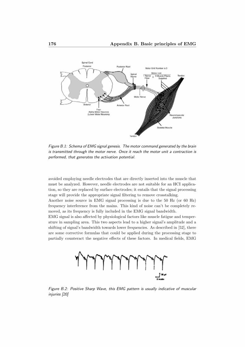
176 Appendix B. Basic principles of EMG
Figure B.1: Schema of EMG signal genesis. The motor command generated by the brain
is transmitted through the motor nerve. Once it reach the motor unit a contraction is
performed, that generates the activation potential.
avoided employing needle electrodes that are directly inserted into the muscle that
must be analyzed. However, needle electrodes are not suitable for an HCI applica-
tion, so they are replaced by surface electrodes; it entails that the signal processing
stage will provide the appropriate signal filtering to remove crosstalking.
Another noise source in EMG signal processing is due to the 50 Hz (or 60 Hz)
frequency interference from the mains. This kind of noise can’t be completely re-
moved, as its frequency is fully included in the EMG signal bandwidth.
EMG signal is also affected by physiological factors like muscle fatigue and temper-
ature in sampling area. This two aspects lead to a higher signal’s amplitude and a
shifting of signal’s bandwidth towards lower frequencies. As described in [52], there
are some corrective formulas that could be applied during the processing stage to
partially counteract the negative effects of these factors. In medical fields, EMG
Figure B.2: Positive Sharp Wave, this EMG pattern is usually indicative of muscular
injuries [20]
177
signal analysis is mainly employed to identify some muscular or nerve diseases. For
example, figure B.2 shows a pattern called Positive Sharp Wave: the signal has
a very sharp positive deflection off the baseline followed by a slower return to the
baseline. This pattern is usually indicative of muscular injuries and can easily be
detected when a muscle fiber is denervated.

“Success is not final. Failure is not fatal.
The courage to continue is what counts.”