equipment cleaning carl fromm - infohouseinfohouse.p2ric.org/ref/30/29497.pdf · minimization of...
TRANSCRIPT

Equipment Cleaning
Carl Fromm

I
Session I1 Source Reduction
MINIMIZATION Of PROCESS EQUIPMENT CLEANING WASTE
Carl H. Fromm
Srinivas Budaraju
Susanne A. Cordery
Jacobs Engineering Group Inc. HTM Division 251 South Lake Avenue Pasadena, Cal i fornia 91101
ABSTRACT
The was te associated with cleaning of process equipment is probably a s ignif icant
contr ibutor t o t h e t o t a l was t e volume generated by industry. This paper addresses t h e
following a spec t s r e l a t ed to equipment cleaning was te generation:
o o Reduct ion of c leaning frequency
Review of reasons for cleaning process equipment
o
o Cos t s assoc ia ted wi th cleaning
Reduct ion of quant i ty and toxici ty of cleaning was te
Equipment cleaning techniques, media , and the i r appl icat ions are reviewed. Reduct ion
of cleaning frequency is addressed in t e rms of inhibition of fouling through proper
squipment design and operat ion, maximizat ion of equipment dedication, proper
production scheduling, and avoidance of unnecessary cleaning. When cleaning has t o
be performed, t h e quant i ty and toxicity of result ing was te can be minimized by
reducing clingage, amount of cleaning solution, choice of less toxic cleaning solution,
cleaning solution reuse, and o the r approaches. Application examples are given t o
i l lustrate e a c h approach.

INTRODUCTION
The current costs o f waste disposal and treatment, regulatory pressure, and concerns
about legal l iab i l i t ies have been forcing IJ.S. industries t o scrut in ize their hazardous
waste generation pract ices L/. A pr imary objective of these e f f o r t s has been t o
min imize waste generation, i.e. t o reduce the quant i ty and t o x i c i t y o f the waste.
O f the many industr ia l waste-generating operations, process equipment cleaning (PEC)
i s nearly universal in i t s appl icat ion, as i t is pract iced in all segments of manu-
factur ing industry. PEC is o f par t icu lar importance f o r discrete processes such as
batch reactions, compounding, surface coat ing operations, etc. This is because the
cleaning frequency f o r discrete processes i s generally much higher than f o r continuous
processes. However, this does no t mean tha t cleanup wastes f r o m continuous
processes can be ignored. Disposal of sludges f r o m cleaning o f heat exchanger foul ing
deposits, fo r example, i s o f t e n o f concern t o the operators o f pet ro leum refining,
petrochemical and chemical process faci l i t ies.
The in ten t o f th is paper i s t o rev iew basic waste min imizat ion strategies appl icable t o
cleaning operations. The in ten t i s to provide a s t ructured classi f icat ion of such
strategies presented in the f o r m o f a prototype checkl ist which can be used t o help
focus and plan a concerted a t tack on waste.
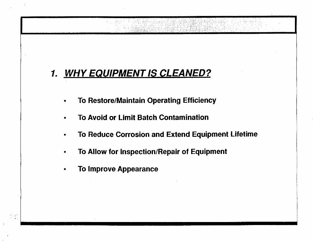
WHY EQUIPMENT IS CLEANED
Equipment cleaning i s a maintenance funct ion typ ica l ly per fo rmed for the fo l lowing
r e as0 ns:
- t o restore or main ta in the operat ing ef f ic iency o f equipment, e.g., t o
restore adequate heat t ransfer ra te and low pressure drop in heat
exchangers. - t o avoid or l imit product contamination, e.g., when a paint m i x tank needs
t o be cleaned between batches of varying paint formulations.
t o min imize corrosion and extend equipment l i fe t ime.
t o al low for inspect ion and repai r o f equipment.
t o improve appearance (exter ior surfaces only).
- - -

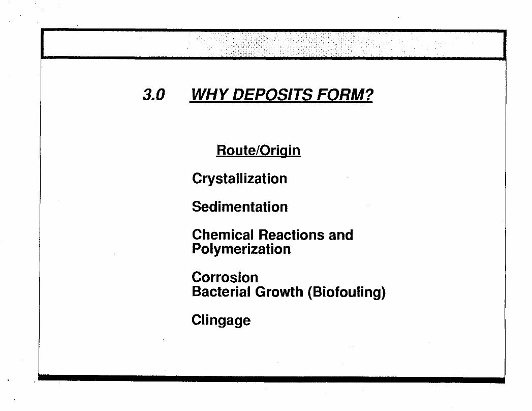
The need f o r cleaning is a d i rec t consequence of deposits fo rmed on t h e sur faces
exposed t o t h e process environment. Some of t h e major routes and origins of deposit
format ion are summarized in Table 1 along with descriptions and s o m e examples.
Understanding how and why t h e deposits a r e formed is a c r i t i ca l first s t e p in any waste minimization e f for t . I t is an especially important a spec t for equipment and
process designers, because t h e need for equipment cleaning can o f t en be reduced or e l iminated through design modifications a t minimal expense during the design s tage .
A common sense approach t o minimizing was te f rom equipment cleaning opera t ions is
to pose and answer the following sequence of questions:
- - how can cleaning be curtai led or avoided (i.e., c leaning frequency
why is t h e deposit present?
reduced)?
- when cleaning is necessary, which cleaning method and medium will
g e n e r a t e t h e leas t amount of l ea s t tox ic waste?
Sect ions below address major a spec t s re la ted t o t h e l a s t two questions.
REDUCTION OF CLEANING FREQtlENCY
Generally, t h e need fo r cleaning can be reduced or avoided a l toge the r by t h e
application of t h e following measures:
- - maximizing dedicat ion of process equipment t o a single formulat ion or
inhibition of fouling or deposi t format ion rate .
function.
- proper production campaign scheduling.
- avoidance of unnecessary cleaning.
Inhibition - of fouling is of par t icu lar impor tance in hea t t r ans fe r appl icat ions where it
can be accomplished through a variety of means, including use of smooth h e a t t ransfer
sur faces , lower fi lm tempera tures , increased turbulence, control of fouling precursors
and proper choice of exchanger type.

TABLE 1. TYPICAL ROUTES AND ORIGINS OF DEPOSIT
FORMATION IN PROCESS EQUIPMENT
Route/Origin Description
Crystal l izat ion
Sedimentat ion
Major problem in evaporators and crystal izers (e.g. very f r equen t in food processing).
Major problem in petroleum ref inery crude unit desal ters and oil s t o r a g e tanks. Also present in cooling tower basins.
Chemical react ions and polymerization Buildup on the internal r e a c t o r sur- faces are of ten encountered (e.g. allyl chloride synthesis). Also of importance in c rude oil s to rage tanks.
High t e m p e r a t u r e coking
Corrosion
Bacter ia l growth (biofouling)
Clingage (of importance to solvent
. cleaning applications)
Carbonaceous mater ia l depositing on walls of furance tubes (e.g. fu rnace fo r ethylene chloride pyrolysis).
Common problem in h e a t exchangers in chemicals and allied products industry.
Major problem on cooling-water-side of h e a t exchangers in e l ec t r i c power production.
Residual c o a t of process liquid l e f t after drainage; major problem in r e a c t o r s and mixers in t h e paint manufactur ing industry and generally in all high-viscosity liquid t r ans fe r operations.
The use of smooth h e a t exchanger surfaces results in lowering the adhesion of the
deposit or its precursor t o the surface. Application of electropolished s ta inless s t e e l
tubes in a fo rced circulation evaporator used in black liquor service in a paper mill
resulted in a d rama t i c reduction of cleaning frequency f rom once a week t o once a
year 2/. Smooth non-stick surfaces can also be provided by Teflon (a regis tered t r ademark of E.I. Dupont de Nemours Sr Co.). Teflon heat exchanger designs a r e
commercially available, as are designs utilizing Teflon coated steel . In a s e p a r a t e
application, condensers using Teflon-coated tubes have been shown t o drastically
reduce fouling and resis t corrosion while maintaining high thermal efficiency. The
higher cost of ma te r i a l was weighed against reduced energy cost t o show a 69 pe rcen t
r e tu rn on investment in the first year before tax =/. If reduced cleaning costs were
to be added, t h e ROI would have been higher.
The rate of h e a t exchanger fouling in a given service is dependent upon fluid velocity
and, qui te of ten, on fi lm temperature . Film t empera tu re controls t h e speed of
chemical react ions which resul t in deposi t-forming compounds while fluid velocity
controls t h e shea r r a t e at t h e fluid-deposi t interface.
Hence, lowering t h e t e m p e r a t u r e of the heat ing medium and increasing t h e fluid
velocity (e.g. by recirculation) can produce a desired reduction of t h e fouling rate. An
economic trade-off analysis between the inc rease in pumping c o s t and t h e dec rease in
t h e cost of cleaning and o the r possible savings appears warranted in investigations
relating t h e deg ree of oversizing t o cleaning w a s t e generation. A general review of
t he rma l and hydrodynamic aspects of h e a t exchanger fouling w a s provided by
Knudsen 21.
Control of deposit precursors is .often an obvious practical consideration. Proper
ma in tenance of cooling w a t e r quali ty in open circulating sys t ems is of paramount
importance to water-side hea t exchanger fouling. Control of hardness, pH, corrosivity
and biofouling tendency is accomplished through careful monitoring of w a t e r
quality E/ . In par t icular , biocides added in treatment must propagate t h e e n t i r e
cooling fluid pa th in order t o be deposited and function a t all locations in t h e
exchanger; and acid f eed equipment t o maintain the pH in the non-scaling range of
6 to 7 mus t be rel iable or else rapid scaling or corrosion problems occur I / .
The choice of h e a t exchanger type can influence cleaning frequency. For example,
spiral p l a t e exchangers a r e o f t en specified over o the r designs in fermentat ion plants,

owing to the e a s e of solid resuspension, absence of pockets, and non-plugging
character is t ics . Rod baff le design provides more effective shell-side turbulence a t lower pressure drop compared to a more conventional segmented baf f le design.
Therefore , t h e rod baff le design can be expec ted to exhibit superior shell-side fouling
charac te r i s t ics .
Slowing down the r a t e of deposit formation is not l imited t o hea t exchangers, bu t a lso
is impor tan t for o the r types of equipment. For example, crude oil's exposure t o
a tmospheric oxygen can cause formation of gums and resins during long exposure
periods inside s to rage tanks. The use of floating roof tanks o r iner t gas blanketing has
been suggested as a way t o reduce t ank deposi t buildup si. Similarly, in paint
manufactur ing, exposure t o air causes formation of solid fi lms t h a t adhere strongly to
the internal sur face of t he mixers. This can be avoided by using closed s to rage and
t ransfer systems, as evidenced by experience a t Ford Motor Company. A t Ford, t h e
paint s to rage and t ransfer sys tem was enclosed and redesigned f o r full recirculat ion
result ing in less f requent and eas ie r cleanups and an improvement of paint quali ty 21. Other applications of fouling inhibition include coat ing of reac tor in te rna ls with
special chemica ls t o prevent sca le formation. These prac t ices have been used in t h e
suspension polymerizat ion process for polyvinyl chloride 61.
Maximizing dedicat ion - of process equipment t o a single process func t ion or formulat ion will reduce cleaning frequency, as t h e frequency of switching t o d i f f e ren t
formulat ions will diminish. Maximum dedication means e i ther converting f rom a ba tch
to a continuous process or using t h e equipment in te rmi t ten t ly just for one formulation.
Historically, t h e changeover f rom ba tch or cyc l ic t o continuous operat ions has been . common in t h e chemica l industry, .owing t o increased product demand, increased labor
costs and technological progress. The advantages of t h e continuous process over ba t ch
include t h e ease of automat ion and control (which minimizes human e r ro r leading t o
inferior product quali ty) and lower labor requirements .
The choice be tween t h e continuous or ba tch mode is governed primarily by production volume and r e l a t ed t rade-offs between capital and operat ing costs. The ba tch process
is advantageous in s i tua t ions where production volumes are small and product diversity
large. Batch processes have proven advantageous even for cer ta in la rge volume
1
products, such as, neoprene
- -7- .’ were developed but fa i led t o
rubber and phenolic resins, where continuous a l t e rna t ives
find wide application %/.
Dedicating a piece of equipment t o a single formulation in t h e batch process means
t h a t the equiprnent remains dormant between individual production campaigns.
Cleaning a f t e r each campaign can be avoided provided t h a t ma te r i a l s l e f t in t he
equipment do not d e t e r i o r a t e with t ime or corrode t h e internals. Also, t h e cos t
penalt ies associated with equipment under-utilization must be outweighed by cleaning
cos t s incurred when t h e equipment is used with m o r e than o n e formulation.
Proper production scheduling is a commonly invoked method t o dec rease cleaning
frequency. Equipment uti l ization s t r a t eg ie s and t h e resulting production schedules
should be derived through optimization analysis, where t h e object ive is t o meet t h e
desired production goals with due consideration of such constraints as available
equipment, c o s t of turnaround, labor availability, s torage, etc. Meet ing production
goals is t o be accomplished with minimum cost , which includes minimization of cleaning frequency. A gene ra l review of optimum s t r a t egy formulation w a s given by
P e t e r s and T immerhaus ?,/.
However, in a typical s i tuat ion a formal optimization analysis is not used of ten.
Ra the r , a common-sense approach t o production scheduling is used based o n trial-and-
error preparat ion of production bar-charts. To reduce cleaning waste , it is generally
desirable t o schedule long campaign runs, as opposed t o short and more f r equen t runs.
Production schedulers now mus t be aware of t he current was te disposal costs , a n
a spec t t h a t previously could have been ignored.
Avoidance - of unnecessary cleaninq should be one of the goals of was te minimization
audits. A t times, equipment cleaning is performed routinely with l i t t l e or no
consideration of the r a t iona le for the cleaning activity. An ac tua l case is known
where a ball mill was used periodically t o wet-grind a cer ta in powder. The ball mill
with corrosion-proof in t e rna l s was total ly dedicated t o t h e s a m e formulation, a s t a b l e
mixture of inorsanic powders. Ye t , t h e ball mill was cleaned after e a c h use for no
apparent reason, IJpon questioning, t h e only justif ication provided was t h a t t h e o the r
non-dedicated ball mills a t t h e facil i ty were cleaned a f t e r eve ry use.

REDUCTION ff QUANTITY AND TOXICITY OF CLEANUP WASTE
When cleaning has to be performed, it should be performed e f f ec t ive ly with minimal
generation of waste. Typical considerations include t h e choice of cleaning medium, cleaning technique and w a s t e disposal option. A brief overview o f t hese choices (with
the exception o f waste disposal), is provided in the following paragraphs.
A distinction can be m a d e between chemical and mechanical cleaning, Chemical
cleaning requires the use of substances such as those shown in Table 2 which are
employed t o chemically attack t h e deposits and render t h e m e i the r solvent or wa te r -
soluble. The basic r eac t ion types include oxidation, reduction, chelat ion or conversion
of insoluble oxides into soluble salts. Cleaning formulations also include su r fac t an t s t o
lower su r face tension of solution t o allow for f a s t e r penetrat ion and breakup of
deposits.
Physical or mechanical c leaning relies on breaking t h e adhesion of t h e deposit t o a surface using mechanical devices, such as scrapers, squeegees, rags, drag lines, "pigs", lances or through the use of high velocity wa te r jets (hydroblasting). Of t en
mechanical and chemical cleaning are combined, e.g., when high velocity jets are employed with caustic solutions t o attack deposits in paint mix tanks.
According t o a classification developed by Loucks E/, six sepa ra t e cleaning
techniques are distinguished:
- fill-and-empty technique
- circulat ion technique - "flow over" technique .
- gas propel technique
- process s imulat ion technique
- onstream cleaning technique
In the "fill-and-empty" technique, a process vessel is isolated from o the r equipment
and filled with an appropr i a t e cleaning solution. The solution can be hea ted and
ag i t a t ed and, a f t e r a period of 4 t o 8 hours it is drained. Rinse-water or diluted alkali
or acid solutions are then used t o remove residual cleaning chemical. Drained
chemicals and subsequent rinses are either reused, t r ea t ed , recycled or land-f illed

TABLE 2. SOME CHEMICAL CLEANING COMPOUNDS AND THEIR USAGE
Cleaning Compound Chemical Ac t ion Usage Remarks
Corrosive t o steel; tempera- tures must be below 175OF
Hydrochlor ic A c i d
Sul fur ic A c i d
N i t r i c Ac id
Hydrof luor ic A c i d
Sulfamic Acid
C i t r i c Ac id
Dissolves most water scales and corrosion products
Dissolves most corrosion products
Same as HCI
Used on boilers, heat exchangers, p i pe l i nes, e tc.
L i m i t e d use Cannot remove water scales
Used f o r stainless steel and aluminum
Cannot be used f o r copper and ferrous alloys
Dissolves s i l icate deposits Used as an addit ive t o HCI (as ammonium bif luoride)
Very dangerous t o handle
Dissolves ca lc ium salts Used as an addit ive t o HCI Easy t o handle; soluble ca lc ium salts
Dissolves i ron oxides Used most ly t o clean boilers; f requent ly w i t h added ammonia and oxidizers
N o t good for water scale removal
Caust ic Soda, Soda Ash Dissolves o i l and grease Used t o remove o i l and grease before ac id cleaning and t o neutra l ize the acid a f t e r cleaning
Dangerous t o handle
A rnmoni a Forms soluble complexes w i t h copper ions
Used t o remove copper f r o m large boi lers
Needs t o be handled carefu l ly
Ethylene Diamine Tetra-Acetate (:EDTA)
Dissolves water scales a t alkal ine pH's
Used f o r cleaning water systems Expensive w i thout shutdown
Source: References (lo), (20).
depending on the i r composition and the availability of disposal options at t he
particular site. The method uses large quantit ies of chemicals and requires substant ia l
downtime. It is typically applicable t o small vessels, tanks or hea t exchangers.
In t h e "circulation" technique, t he vessel is filled with cleaning solution t o an overflow
and allowed to s tand for a sho r t t ime period, a f t e r which the solution is c i r cu la t ed
with an auxiliary pump. Fresh make-up solution can be pumped in i f used solution is
dithdrawn. In boilers, nitrogen gas is used t o provide agitation f o r more effective
sca l e removal.
The "flow over" technique consists of spraying the solution onto the surface. I t is
applicable t o large tanks where cleaning by filling or recirculation would require
excessive quanti ties of cleaning solution. Extra safety precautions are usually
necessary.
The "gas propel" technique uti l izes cleaning agents t h a t are not overly corrosive at higher t empera tu res when s t e a m is used t o propel t hem through t h e system. This technique is usefu l for pipelines, where inhibited organic acids or che lan t s a r e
entrained into a flow of steam which ca r r i e s t he liquid drops and solids debris through
hydraulic obstacles of t h e system.
The llprocess simulation" technique is applied t o equipment t h a t is easily fouled and
where spare parallel units a r e provided. Fouled equipment is' cleaned by s imulated
process operation, where t h e equipment is isolated, drained o f process fluid and fi l led
with t h e cleaning solution using process pumps and controls t o maintain flow and
temperature . An example is removal of iron oxide and copper deposits f r o m high
pressure steam.generat0r.s using ammoniated EDTA solution.
The "onstream cleaning" technique is probably t h e mos t preferable method, as i t re l ies
on process fluid t o do t h e cleaning during normal operation. Of t en auxiliary mechanical devices are used along with additives, such as EDTA or acids to p romote
deposit removal. This technique is used fo r cleaning r eac to r jackets, gas compression s ta t ion engines, h e a t exchangers , and o the r equipment. In-service cleaning of large
circulating cooling w a t e r systems is of ten done through in t e rmi t t en t pH swing t o t h e
acid side of neutral and back again. Among many mechanical devices used in conjunction with ons t r eam cleaning, one could mention r am valves for rodding ou t

plugged nozzles and moveable hea t exchanger tube inserts propelled by reversing
process fluid 111. In a s e p a r a t e example, the use of fluidized beds of ine r t solids (e.g.,
sand) was found useful in h e a t t r ans fe r applications cha rac t e r i zed by e x t r e m e fouling,
such as heat recovery from geothermal brines. Solid particles constant ly ab rade t h e
deposit away from the hea t t r ans fe r surface, maintaining high t r ans fe r ra tes .
The choice of cleaning method and media, a p a r t f rom cost , should also be based on t h e
following environmental considerations:
- minimize t h e amoun t of cleaning solution used; - -
choose t h e medium ul t imately result ing in t h e l e a s t toxic waste;
determine ahead of t i m e how the cleaning w a s t e is going t o be disposed of.
The use of chemical cleaning (e.g., with mineral or organic acids) resul ts in
appreciable quant i t ies of hazardous cleaning wastes which need t o be t r e a t e d prior t o
disposal. As appropriate t r e a t m e n t faci l i t ies a r e not available ons i t e in eve ry case, mechanical cleaning and ons t r eam cleaning appear preferable t o chemica l cleaning.
According t o information obtained from various cleaning contractors , t h e s e f a c t o r s are gaining recognition as t h e r e c e n t t r e n d has been more toward hydroblasting and
ons t r eam cleaning and away f r o m chemical cleaning. This was a t t r i bu ted t o t h e rising
cos t s of was te disposal and t r e a t m e n t .
When chemical cleaning is unavoidable, t he l e a s t toxic medium should be chosen; for
example, an alkaline c l eane r would be preferable over a halogenated solvent. How-
ever , if the toxici ty of the "soil" t o be removed is the controlling f a c t o r , t h e cleaning
a g e n t with a higher potent ia l fo r recovery and reuse should be used.
An attractive a l t e rna t ive t o those cleaning methods t h a t require disassembly of
equipment fo r cleaning, is a clean-in-place (CIP) system. The s y s t e m is composed of
tanks, h e a t exchangers, f i l ters , pumps, piping and instrumentat ion permanent ly
installed as an auxiliary sys t em designed to circulate a controlled inventory of
cleaning solution through isolated process equipment of ten using spray manifolds or
-*-I--- Iiniiirl j e t nezz!es inside p r e d g c t i o ~ vessels. The C!p systems gener&y reduce t h e
usage of cleaning medium. They are especially e f f ec t ive when coupled wi th high
velocity au tomated jet manifolds and s t aged counter-current rinsing; an 80 t o 90
pe rcen t reduction in aqueous was te was achieved by paint manufac tu re r s a f t e r
installing high pressure spray nozzles fo r tank rinsing g/. CIP systems a r e popular in
food, pharmaceut ical and paint industries; however they a r e uti l ized less frequent ly in
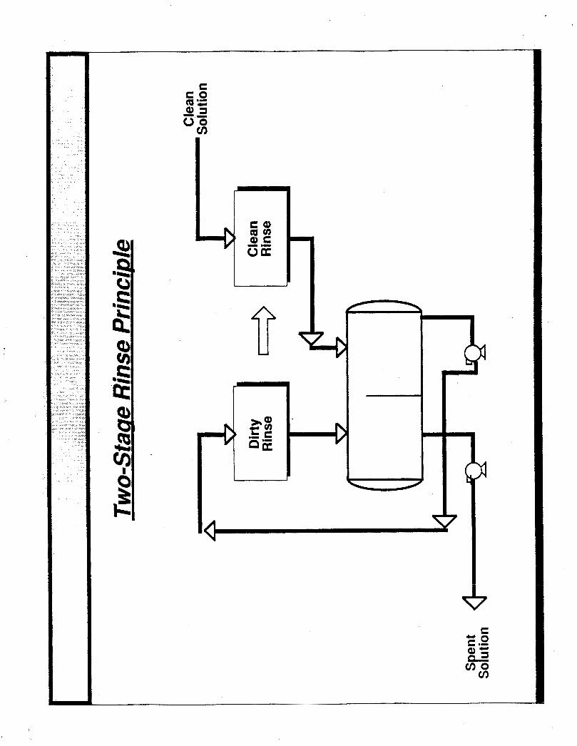
t h e chemical processing industry u/. Reuse of cleaning solutions is common in CIP systems. In general , r euse of cleaning
solutions is highly desirable, especially i f they can be utilized as p a r t of formulation.
For example, a considerable reduction in r eac to r cleanup w a s t e was achieved by
Borden Chemical where a two-step rinse sequence was applied t o a batch k e t t l e
arrangement used for phenolic resin synthesis. The f i r s t rinse used a small amount of
w a t e r generat ing a concen t r a t ed s t r e a m which could be recycled t o t h e process. The second full volume rinse generated was tewa te r with a much lower c o n t e n t of toxic
ma te r i a l t han a previously used single rinse method 141. Other examples include reuse
of rinsewater f rom l a t ex tank cleaning as pa r t of la tex formulat ion in t h e paint
industry 151 and use of w a r m oil f o r flushing t h e deposits ou t f r o m c rude oil s t o r a g e
tanks in a n oil refinery, followed by solids separat ion in the slop oil sys t em !&/.
The preceding sect ions were concerned with reduction of cleaning frequency and with
the choice of t h e l ea s t waste-intensive cleaning methodology. There is a r e l a t ed , b u t
independent a spec t of cleaning w a s t e reduction, i.e., reduction of clingage. As
explained previously, clingage is the amount of process ma te r i a l l e f t inside t h e vessel
or o the r equipment a f t e r draining. In operations involving viscous fluids, such as paint
manufactur ing and resin compounding, clingage is an important consideration as i t not
only resul ts in was te which is expensive t o dispose of, but also r ep resen t s a d i r ec t loss
o f product or raw mater ia l .
To reduce clingage, t h e following measures should be considered:
- - - - - choice of square cylindrical or spherical geometry t o minimize w e t t e d
provision of adequa te drainage t ime;
use of low-adherence surf aces, e.g., fluorocarbon or electropolished steel;
use of mechanical wall wipers (dual s h a f t mixers);
use o f manual wipers or squeegees;
surface;
rotat ion o f ag i t a to r a f t e r batch dumping t o reduce clingage on t h e blade. -
All of the above measures are self-explanatory and do not require elaboration. $Most a r e prac t iced extensively throughout industry. The use of t ank linings a s a means o f
reducing adherence and preventing corrosion has been addressed by Zolin g/ and
Kays !&!I, The use of dual sha f t mixers with slow scraper blades wiping t h e walls and the bot tom of mixing tanks is common in applications involving viscous liquids E/,
COST OF CLEANING
The cos t of cleaning c a n be viewed as being composed of the following elements:
D i rec t C o s t s
- equipment assembly/disassembly
- cleaning chemica ls and supplies
- was te t r e a t m e n t and disposal
- cleaning labor and supervision
- cleaning equipment depreciat ion
- uti l i ty cos t s
Ind i rec t Costs - planning and scheduling
- cost of los t production - - inspection and tes t ing
- process equipment deter iorat ion
cos t of los t raw mater ia l s inventory
Of t en equipment cleaning is performed by outs ide cont rac tors with specialized
equipment who assume t h e responsibility for hauling away t h e w a s t e and for disposing
of i t properly.
Costs of c leaning vary widely depending upon t h e medium, method and application.
R e c e n t inquiries into t h e cost of cleaning of h e a t exchangers es tabl ished t h e following
compilat ion of re la t ive h e a t exchanger cleaning cos t s using con t r ac t ed service:

Method Relat ive C o s t Hydroblas t ing 1.0
Rodding 4 t o 5 Chemical Clean ing:
Without was te disposal 0.3 t o 3
2.1 t o 4 W i t h was t e disposal
In many cases t h e cost of cleaning ( taken as d i rec t cost only) is lumped toge ther with
o the r main tenance costs. As a resul t , p lant management may no t have good visibility
of t h e ac tua l cos ts of cleaning, which may impede management 's support fo r was te
minimization effor ts . Often, when plant management learns of t he true cos t
dimension, ac t ion t o lower cleaning cos ts is quickly init iated.
SUMMARY
As mentioned in t h e introduction, t h e in ten t of this paper is to provide a brief review
of techniques, approaches and s t r a t eg ie s for minimizing equipment cleaning was te and
to provide a classification scheme tha t may serve as an init ial guide t o those
in te res ted in was te minimization. Such a classification or summary is provided in
Table 3. This se rves a s a prototype checkl is t f o r addressing all waste minimization
issues in a logical sequence.
The subject of equipment cleaning is qui te diverse a s the funct ion is performed in
virtually eve ry industry. General izat ions presented in this paper must be t rans la ted
into si te-specif ic and exac t ing requi rements in any was te minimization effor t .
ACKNOWLEDGEMENTS
The authors wish t o express the i r g ra t i tude t o the U.S. Environmental Pro tec t ion
Agency, Of f i ce of Solid Waste, fo r the i r support in developing a substant ia l portion of
the ma te r i a l p resented in th i s paper.

,
TABLE 3. WASTE MINIMIZATION OF EQUJPMENT
CLEANING WASTE - SUMMARY OF APPROACHES
REDUCE CLEANING FREQUENCY
1. Inhibition of fouling r a t e - smooth hea t t r ans fe r sur faces
- lower film temperature/higher turbulence
- control of fouling precursors - choice of h e a t exchanger type
2. Maximize process equipment dedication - - dedication t o single composition
conversion f rom ba tch to continuous operat ion
3. Proper production scheduling
4. Avoidance o f unnecessary cleaning
I
REDUCE QUANTITY AND TOXICITY OF WASTE
1. Minimize amount of cleaning solution
- high pressure nozzles
- flow-over technique
- on-stream cleaning - use of CIP systems with s taged or counter-current
rinsing
- reuse of cleaning solution
Minimize toxici ty of spent cleaning solutions
- clingage reduction -
2.
mechanical (hydroblasting) over chemica l cleaning

REFERENCES
1.
2.
3.
4.
5 .
6 .
7.
8.
9.
10.
11.
12.
13.
14.
15.
16.
17.
League o f Women Voters of Massachusetts, Waste Reduction: The U n t o l d Story, Conference held June 19-21, 1985 a t Nat ional Academy of Sciences Conference Center, Woods Hole, Massachusetts.
Uddeholi n Corporat ion (Sweden), Technical brochure on Tubec Tubes and communications w i t h Avesta Stainless Inc., Totowa, New Jersey
Knudsen, J.G., Foul ing o f Heat Exchangers: Are W e Solving the Problem?, Chem. Eng. Progress, Feb. 1984, pp. 63-69.
Jacobs Engineering Group Inc., Al ternat ives for Hazardous Waste Manaqement Pract ices in the Petro leum Ref in ing Industry, EPA-530-SW-l72C, Washington, D.C., U.S. Environmental Protect ion Agency, 1979.
Colleta, V., Powers, J., Chem Proc. 44(4):20-1, 1981.
Cameron, J.B., Lundeen, A.J., McCulley, Jr. J.H., Hydroc. Proc., 59(3):39-50, 1980.
Euleco S.P.A., Euleco Continuous Process: Technical Bul let in, 1975.
Shell Internat ional Research Inc., Brit. Patent No. 136, 189; issued Dec. 11, 1968.
Peters, M.E., Timmerhaus, K.D., Plant Desiqn & Economics f o r Chemical Enqineers, 3rd Edit ion, McGraw Hill Book Co., 1980.
Loucks, C.M., Boostinq Capacit ies w i t h Chemicals, Chem. Eng. (deskbook issue), 80(5):79-84, 1973.
Water Services o f America, Inc., Superscrubber Technical Bul let in, 1985.
U.S. Environmental Pro tec t ion Agency, O f f ice of Water & Waste Management; Development Document for Proposed Ef f luen t Guidelines, N e w Source Per- formance Standards and Pre t rea tment Standards for the Pa in t Formulat inq, Pa in t Source Category, EPA-440-1-79-0496, Washington, D.C., 1979.
Hyde, J.M., New Development in CIP Practices, Chem. Eng. Progress 81(1):39-41, 1985.
6
Huisingh, D., et. al., Proven P r o f i t f rorn Pol lu t ion Prevention, The I n s t i t u t e f o r L o c a l Self-Reliance, Washington, D.C., 1985.
Ri ley, J.E., Development Document fo r E f f luen t L i m i t a t i o n Guidelines, New Source Performance Standards f o r t h e T i re and Synthetic Segment of t h e Rubber Processinq Industry, P o i n t Source _ _ Cateqory, EPA-440-1-74-013A, U.S. Environ- menta l Pro tec t ion Agency, 1974.
Barnett, J.W., Bet ter *Nays t o Clean Crude Storage Tanks and Desalters, Hydroc. Proc. 60(1):82-86, 1980.
Zolin, B.I., Chem. Proc. 47(9):63-5, 1984.

REFERENCES (Continued)
18.
19.
20.
21.
Kays, 'N.B., Construct ion o f Lininq f o r Reservoirs, Tanks & Pollution Control Facil i t ies, Wiley, New York, 1979.
Myers Mixing Company: pr ivate communication, 1985.
Betz Laborator ies Inc., Handbook o f Industrial Water Conditioning, 8 t h Ed., Trevose, Pennsylvania 1980.
Paschke, L.F., Condensing Hea t Exchangers Save Heat , Chem. Eng. Progress , pp. 70-74, July 1984.


MINIMIZATION OF PROCESS EQUIPMENT CLEANING WASTE
CARL H. FROMM
JACOBS ENGINEERING GROUP INCORPORATED PASADENA, CALIFORNIA
Presented at the U.S. EPA SYMPOSIUM ON
SOLVENT WASTE REDUCTION ALTERNATIVES

CONTENTS
1.
2.
3.
4.
5.
6.
7.
Why Equipment is Cleaned?
Conceptual Approaches to Waste Minimization
Why Deposits Form?
Reduction of Cleaning Frequency
Reduction of Quantity and Toxic of Cleanup Waste
Cost of Cleaning
Summary
I . WHY EQUIPMENT IS C LEANED?
To Restore/Maintain Operating Efficiency
To Avoid or Limit Batch Contamination
To Reduce Corrosion and Extend Equipment Lifetime
To Allow for Inspection/Repair of Equipment
To Improve Appearance

Reaso ns for Interest in Reduct ion of Process EauiDment Cleanina (PEC) Waste
a) PEC - A Widespread Industrial Practice.
b) PEC Waste - Probably Represents a Significant Frac- tion of All Hazardous Waste Generated.
c) Economics (High Cost of Treatment and Disposal)
d) Land Disposal Ban
e) Liability Issues
f) Regulatory Incentives
g) Future Regulation
3.0 WHY DEPOSITS FORM?
Rou te/O r isi_ll
Crystallization
Sedimentation
Chemical Reactions and Polymerization
Corrosion Bacterial Growth (Biofouling)
Clingage
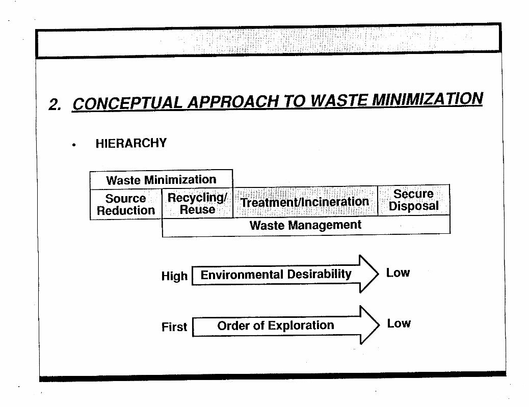
CONCEPTUAL APPROACH TO WASTE MINIMIZATION
HIERARCHY
Hiah 1 Environmental Desirability Low
First I Order of Exploration Low I

Minimization of PEC Waste
Order 1.
Exploration 2. of
Why Deposit is Present?
How Can Cleaning Frequency Be Reduced?
Which Cleaning Method/Medium Will Produce Least Amount of Least Toxic Waste?
How to TreaVDispose of Residuals in an Environmentally Safe and Cost Effective Way?
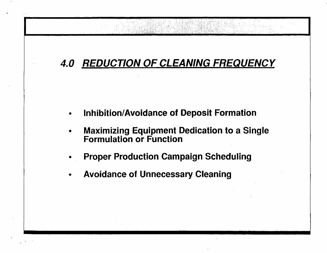
4.0 REDUCTION OF CLEANING FREQUENCY
Inhibition/Avoidance of Deposit Formation
Maximizing Equipment Dedication to a Single Formulation or Function
Proper Production Campaign Scheduling
Avoidance of Unnecessary Cleaning

/nhibitition/A voidance of Deposit Information
Foulina Prevention in Heat Exchangers
Use Non-Stick Tube Surfaces Control of Deposit Precursors Choice of Heat Exchanger Type
Foulina Prevention in Other ApDlications

lnhibitition/A voidance of Deloosit Information
Fouling Prevention in Heat Exchangers
ApDroach: Use Non-Stick Tube Surfaces
Appearance of a. standard tube and a Tubec rube, respec- tively, after use in a black liquor evaporator.
. .
Electropolished Tubes fcourtesv of Avesta Stainless Co.)

FOULING PREVENTION IN HEAT EXCHANGERS
Approach 2: Low Film Temperatures and Higher Turbulence.
Increasing / Surface Temperature
-
Velocity V
Source: Garret-Price, et.al.; "Fouling of Heat Exchangers", Noyes Publications, 1985.

FOULING PREVENTION IN UEAT EXCUANGERS
Awroach 3: Control of Deposit Precursors = e.g. pH and Biocide Concentration in Cooling Water
Approach 4: Choice of Heat Exchanger Type
Spiral Plate Exchanger Schematic

1NHlBITlON OF DEPOSIT FORMA TION - NOT ONL Y LIMITED TO HEAT EXCHANGERS
ExamDles
Problem
Formation of Gums and Resins In Crude Oil Storage Tanks.
Drying of Paints in Mixing Tanks and Application Equipment.
Tar Formation in Allyl Chloride Synthesis Reactor.
Solution
Limit 0, Exposure by Floating Roofs or Nitrogen Blanketing.
Enclosed Recirculation System.
Re-Design lnternals to Increase Turbulence.

One Tank - Two Products MAXIMIZING EQUIPMENT DEDICATION TO A SINGLE FORMULATION OR FUNCTION
-b
Two Products - Each With a Dedicated Tank
- *_m_
W Time A A
---
6 B
0 Avoldance of Unnecessary Cleanlng
4.0 OF F R F Q E K U
0 lnhlbltlon of Deposlt Formatlon Rate
Maxlmldng Equlpment Dedlcatlon to a Slngle . Formulatlon or Functlon
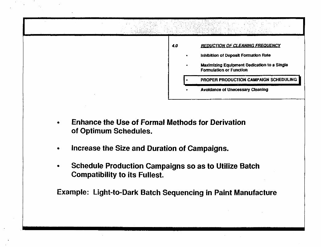
I* PROPER PRODUCTION CAMPAIGN SCHEDULING
0 Avoldance of Unecessary Cleanlng
Enhance the Use of Formal Methods for Derivation of Optimum Schedules.
Increase the Size and Duration of Campaigns.
Schedule Production Campaigns so as to Utilize Batch Compatibility to its Fullest.
Example: Light-to-Dark Batch Sequencing in Paint Manufacture

4.0 OF-
* lnhlbltlon of Deposlt Formatlon Rate
Maxlmlzlng Equipment Dedlcatlon to a Single Formulatlon or function
. Proper Productlon Campaign Scheduling
AVOIDANCE OF UNECESSARY CLEANING
Dedicated Equipment Need Not to be Cleaned After Each Use.
Cross Contamination Between Batches of Different Products May Not Be Serious Enough to Warrant an Intermediate Cleaning Step.

5.0 REDUCTION OF QUANTITY AND TOXICITY - OF CLEANUP WASTE WHEN CLEANING IS - UNAVOIDABLE
Proper Choice of Cleaning Method & Medium
Reduction of Clingage
Reuse of Cleaning Solution

w
5 c 9) S: 0
0
'D 111 0 'D m 3 0
0 m 0 n 0 r m D

0 e e e e
v) 0 - ni m I).
3 (13
cii cta 5 I.
=13 0 9. a I.
(P U c 0 3 (P
.I.
v) 0 - r-
3 v)
rc
0 E E' 5'
X
ca v) 0
0 0 3 v c X
b c) .. I m
P, v)
b
I
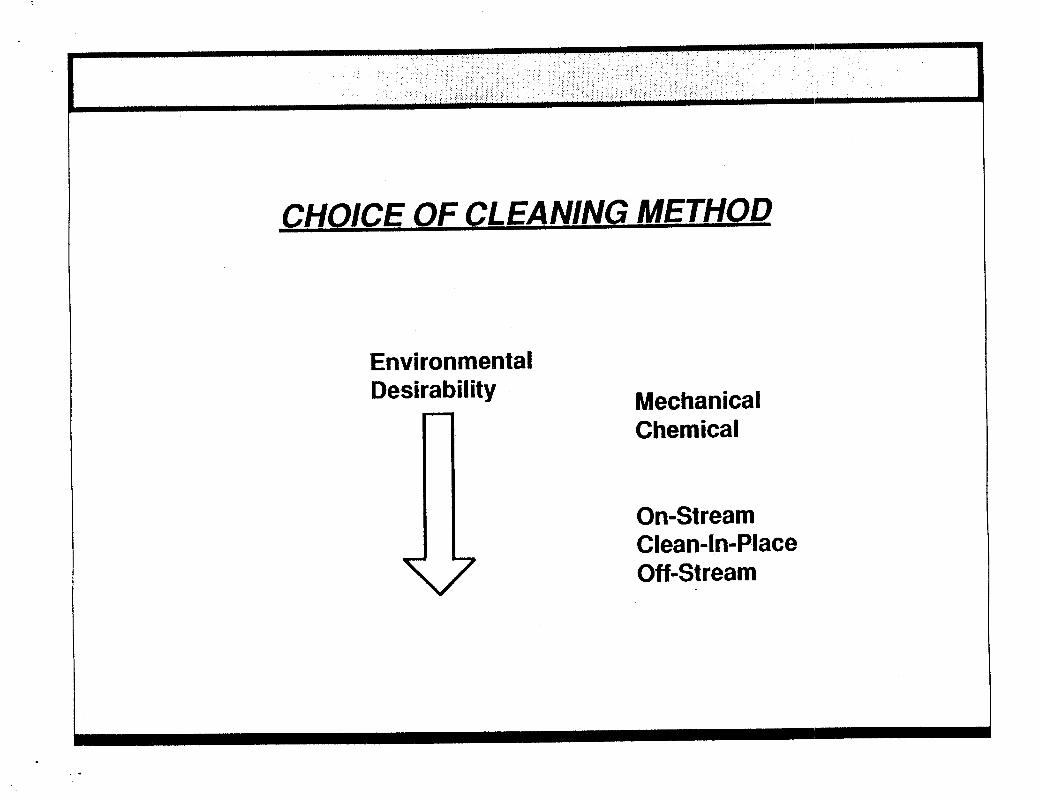
CHOICE OF CLEANING METHOD
Environmental Desirability a Mechanical
Chemical
On-Stream Clean-In-Place Off-Stream

On-Stream Cleaning Amertap Sponge Ball Cleaning System
c Fluidized Bed Exchangers pHSwings Ramvalves Dual Shaft Mixers
0 "Pigging" of Pipelines
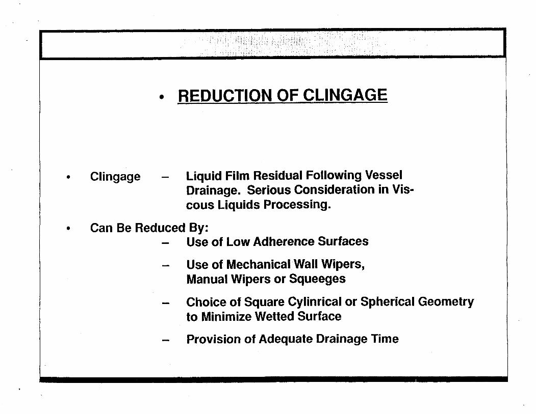
REDUCTION OF CLINGAGE
Clingage - Liquid Film Residual Following Vessel Drainage. Serious Consideration in Vis- cous Liquids Processing.
Use of Low Adherence Surfaces
Use of Mechanical Wall Wipers, Manual Wipers or Squeeges
Choice of Square Cylinrical or Spherical Geometry to Minimize Wetted Surface
Provision of Adequate Drainage Time
Can Be Reduced By: - -
-
-
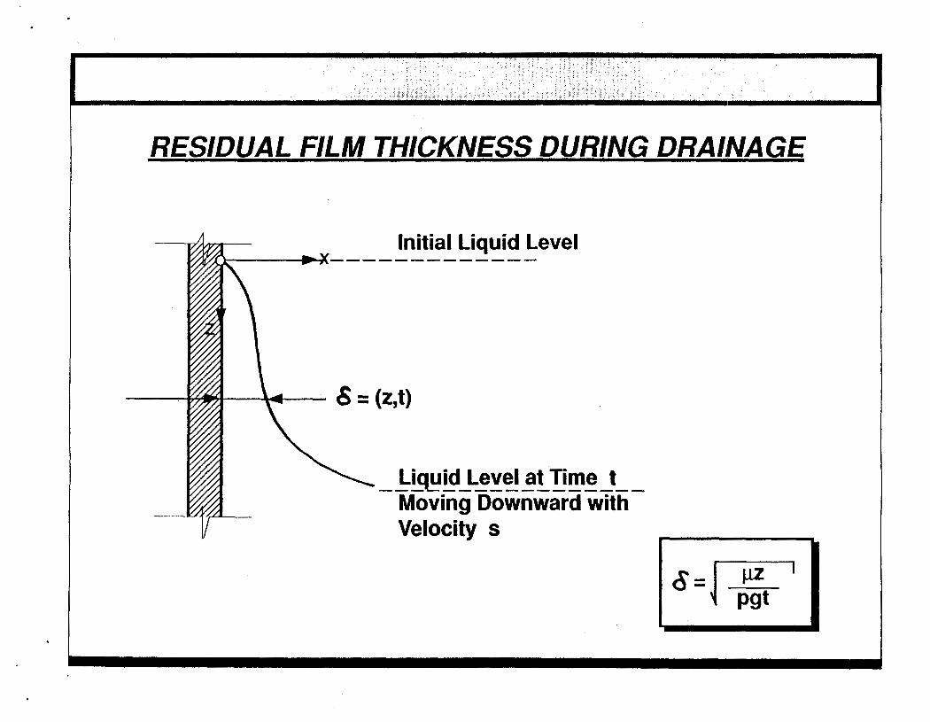
RESIDUAL FILM THICKNESS DURING DRAINAGE
---Am-- Initial Liauid Level
6 = (2,t)
\ Liy id ------------- Level at Time t Moving Downward with Velocity s

Reuse of Cleanina Solutions
Re-Use of Spent Cleaning Solution in Next Compatible Batch
Multistage/Counter-Current Rinsing
Recovery

CLEAN4N-PLACE SYSTEM WITH SOL VENT RECOVERY
* I Mixer .m J I
\
4 Product J
1 Spent Solvent I 0 7
Other Users
Swam Still 1111) u L
C
a- a0 cn
E .2 LJ

7.0 SUMMARY
UNDERSTAN D REASOB EQIumNw
InhibWAvoid Deposit Formation Maximize Equipment Dedication Properly Schedule Production Campaigns Avoid Unnecessary Cleaning
REDUCE QU ANTlTY/TOX CITY OF CLEANING WASTE
Properly Choose Cleaning MethodMedium Reduce Clingage Reuse Cleaning Solution

6.0 e
0
e
COST OF CLEANING Direct Costs
- Equipment Assembly/Disassembly - Cleaning Chemicals and Supplies - Waste Treatment and Disposal - Cleaning Equipment Depreciation - Utility Costs
Indirect Costs
- Planning and Scheduling - Cost of Lost Production - - Inspection and Testing - Equipment Deterioration
Cost of Lost Raw Material Inventory
Cleaning Usually Lumped Together With Other Maintenance Costs

- .. _.~. .
GEPA
Unlted Stated Center for Envlronmental offlce cf Solld Waste Environmental Protectlon Research informatkn and Emergency Response A g e w __- Technology Transfer March 1988 CERI-88-06
Solvent Waste Reduction Alternatives Seminar
Speaker Papers
'
