e.proofing - digital.csicdigital.csic.es/bitstream/10261/102963/4/graded anodes.pdffinally, a...
TRANSCRIPT
J. Beltrán
M. A. Laguna-Bercero
Email [email protected]
J. Gurauskis
J. I. Peña
Instituto de Ciencia de Materiales de Aragón (ICMA), CSIC—Universidadde Zaragoza, C/Pedro Cerbuna 12, 50009 Zaragoza, Spain
Present Address: Department of Energy Conversion and Storage, TechnicalUniversity of Denmark, Frederiksborgvej 399, 4000 Roskilde, Denmark
Graded anodes for anode-supported solid oxide fuel cells are fabricated bytape casting and subsequent cold lamination of plates using differentcompositions. Rheological parameters are adjusted to obtain stablesuspensions for tape casting. The conditions for the tape casting andlamination will be described. Flexural strength of the reduced cermetsmeasured using three-point bending configuration is 468 ± 37 MPa. The
graded anode supports are characterized by scanning microscopeobservations, intruded mercury porosimetry, and resistivity measurements,showing an adequate and homogeneous distribution nickel, zirconia, andpores. The laminated samples showed a total porosity of 18.7 % (in vol%)and a bimodal pore size distribution centered in 20 and 150 nm, and themeasured electrical resistivity of this sample was 120 ± 12 μΩ cm. Thenovelty of the present work is the lamination of tapes at room temperaturewithout using plasticizers. This is made by the combination of two differentbinders with varying T (glass transition temperature) which resulted inplastic deformation at room temperature. Those results indicate that the
1
1,*
1,2
1
1
2
g
e.Proofing http://eproofing.springer.com/printpage.php?token=IJvnCAkBtPXT-f_b...
1 de 15 07/03/2014 9:59
proposed process is a cost-effective method to fabricate anode-supportedSOFCs.
Tape castingLaminationAnode-supportedSOFCNi-YSZ
Solid oxide fuel cells (SOFCs) are attractive devices for clean energy
generation as they can produce electricity from a large variety of fuels and
also present low environmental impact and high efficiencies [1 , 2 ]. State-of-the-art SOFC materials are typically an yttria-stabilized zirconia (YSZ)electrolyte, a Ni-YSZ anode, and a lanthanum strontium manganite
(LSM)-YSZ cathode, although a large number of materials can be used [3 , 4 ].When a SOFC operates in the reverse mode, these devices are capable toproduce hydrogen from steam and electrolysis of CO Coelectrolysis of steam
and CO is also feasible [5 ].
Tape casting is a cost-effective technique for producing thin, flat, and large
area ceramic tapes [6 , 7 ]. However, it has some drawbacks such as limitedstrength and low dimensional stability due to its intrinsic properties offorming mechanism. In order to resolve this problem, laminating and co-firingof green tapes have been proposed as additional processes in the recent years
[8 – 11 ]. Savignat et al. [8 ] optimized the conditions to obtain dense samples
with a suitable thickness and a good flatness of apatite electrolytes and
Ni/apatite-type electrodes by tape casting and lamination. Moon et al. [9 ] alsodeveloped anode-supported thin electrolytes by tape casting and co-firing,which could be cost-effective for mass production of SOFC single cells. Theydeveloped this technique for manufacturing excellent anode-supported thinelectrolytes via tape casting, laminating the green tapes, isostatic-pressing,burning out of the binder, and then co-firing. Their cells showed excellentelectrical and electrochemical at intermediate temperatures (550 mWcm at
700 °C). In addition, Park et al. [10 ] optimized the flatness of the anode-supported electrolyte by controlling the firing schedule, the lamination
method, and the applied load during firing. Finally, Li et al. [11 ] fabricated
2.
2
−2
e.Proofing http://eproofing.springer.com/printpage.php?token=IJvnCAkBtPXT-f_b...
2 de 15 07/03/2014 9:59
NiO-YSZ and NiO-SDC anode-supported SDC film electrolytes bylaminating 24 sheets of anode and one sheet of electrolyte and co-firing andobtained a maximum power density for the anode-supported SDC electrolytesingle cell of 93 mW cm at 800 °C using hydrogen as fuel.
In order to fabricate anode supports with graded composition and porosity,several approaches have been widely discussed in the literature. For example,subsequent layers varying the NiO:YSZ ratio will lead to a gradient on Nimetallic particles and pores after NiO to Ni reduction and, as a consequence,varying the triple-phase boundary (TPB) length. Another approach to controlthe porosity, in particular for the lamination process, will be the variation ofthe thickness reduction when laminating the layers. Third approach will be theaddition of pore formers such as starch, graphite, or poly(methyl methacrylate)(PMMA) particles in order to increase the porosity specially in the furtherregion of the electrolyte.
However, the literature about tape casting and lamination fabrication processis still reduced. For this reason, the objective of the present study is the
fabrication of graded NiO-YSZ anodes by tape casting and cold lamination.Control of the porosity will be performed varying the composition of the NiOcontent from 50 to 70 % in volume and also varying thickness reductionduring lamination. Graded electrodes are essential for anode-supported cells.Tape casting and lamination are probably the cheapest method to produce thistype of cells. The novelty of the present work is the lamination of tapes atroom temperature without using plasticizers. This is made by the combinationof two different binders with varying T (glass transition temperature) whichresulted in plastic deformation at room temperature. The absence ofplasticizers will simplify the process on an industrial scale application byreducing both costs and environmental issues. For this purpose, optimizationof the ceramic suspensions for tape casting will be performed. In addition, the
conditions for cold lamination and sintering parameters will be adjusted.Characterization of the samples will be performed by optical and SEMmicroscopy analysis; the study of the mechanical properties will be analyzedby flexural strength. Finally, pore distribution will be studied by Hgporosimetry, and electrical DC resistivity measurements will be alsoperformed.
As the starting powders for the anode precursors, we have employed 8YSZ
−2
g
e.Proofing http://eproofing.springer.com/printpage.php?token=IJvnCAkBtPXT-f_b...
3 de 15 07/03/2014 9:59

(8 mol% yttria-stabilized zirconia, TZ-8YSZ, Tosho, Japan) with a meanparticle size of 0.52 μm, and NiO (Alfa Aesar GmbH & Co. KG, Germany)with a mean particle size of less than 44 μm. For the suspension fabrication,polyacrylic acid-based polyelectrolyte (D-3005, Rohm & Haas France S.A.S.)
was used as dispersant, and two acrylic polymeric emulsions, DuramaxB-1235 (Rohm & Haas France S.A.S. T = −26 °C) and Duramax B-1000(Rohm & Haas France S.A.S. T = 14 °C), were employed as binders. Asilicon-based wetting agent was also used (BYK-348, BYK-Chemie GmbH,Germany). Finally, a mineral oil and silicon-based defoamer (BYK-35,BYK-Chemie GmbH, Germany) were also occasionally employed to eliminatebubbles. NiO powders were previously milled in an attrition mill for 30 minusing 2-propanol as solvent in order to obtain a mean particle size of 1.2 μm.Particle size of the powders was determined using dynamic light scattering(DSL) (Malvern Instruments Ltd., UK).
In order to determine the appropriate amount of dispersant, a set ofsuspensions of different powder concentrations were prepared and
characterized by their zeta potential using a Z-Sizer nano ZS (MalvernInstruments Ltd., UK). In addition, rheological measurements were performedusing a rotational rheometer using the Rheowin software (Haake Mars,Thermo Scientific, Germany). For this purpose, a set of suspensions withnarrow range of proportions of powders and concentrations of dispersant,according to the information provided by the zeta potential, were analyzed.The measurements were performed operating in control rate (CR) mode at20 °C, and the conditions were from 0 to 1,000 s in 150 s, maintaining atthis rate for 30 s and coming back to 0 s using the same rate. All the slurrieswere prepared by adding the powders into deionized water using the requiredamount of dispersant under constant mechanical stirring. After stabilization,the slurries were exposed to ultrasonic milling for 10 min and then ball-milled
during 2 h at 150 rpm. Binders and wetting agent were finally added, and themixtures were magnetically stirred for 24 h.
Tape casting was performed on a stationary polypropylene film using a movingtape casting device with two doctor blades. The casting parameters wereadjusted to 15 mm s of casting velocity and 150 μm gap between blades andthe carrier film. After drying in air at room temperature conditions for 24 h,the green tapes were cut to an appropriate size and sintered at 1,400 °C.Density of the sintered bodies was calculated using the Archimedes method.The anodes were finally heated up to 850 °C under inert atmosphere and then
g
g
−1
−1
−1
e.Proofing http://eproofing.springer.com/printpage.php?token=IJvnCAkBtPXT-f_b...
4 de 15 07/03/2014 9:59
reduced for 6 h using 5 %H /Ar atmosphere.
Flexural strength of the reduced cermets were determined according to ASTM1161-02c standard using a three-point assembly in an Instron 5565 testmachine (Instron, USA) at a test speed of 10 μm min .
Graded anodes were finally fabricated by cold calendering of the green tapes.Adhesion tests were performed in order to determine the appropriate degree ofcompression for the calendering process. Microstructural studies wereperformed by field emission scanning electron microscope (FE-SEM) analysisusing a Merlin FE-SEM (Carl Zeiss, Germany). We have also performed astudy of the volume fraction of the different phases (nickel, YSZ, and pore)by image thresholding using DigitalMicrograph (TM) 3.10.0 (Gatan Inc.,USA) software. For this purpose, three different images for each sample takenwith identical magnification (×5,000) were analyzed. Particle size wascalculated using the interception method and TPB length (expressed in μm )
was also calculated in a similar manner as described in [12 ].
Porosity of the anode layers after sintering was also measured by Hgporosimetry using a Micromeritics Autopore II 9215 porosimeter.Conductivity measurements were performed using the four-point configurationat RT using a 220 Keithley Programmable current source and a HewlettPackard 34401A microvoltmeter.
Previous studies in our laboratory showed that, for a 50NiO-50YSZ (in vol%)paste, the best slurry conditions for tape casting are those summarized in
Table 1 [13 ]. In this work, it was necessary to adjust binder, dispersant,
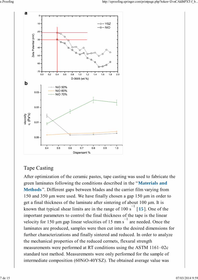
wetting agent, and defoamer amounts for two new slurry compositions:60NiO-40YSZ and 70NiO-30YSZ (in vol%). The amount of dispersant wasadjusted after studying the zeta potential. As a first approach, 0.4 % (inweight%) was selected for all compositions, as this amount gives zetapotential values between −20 and −30 mV for both NiO and YSZ, as observed
in Fig. 1a . Zeta potential values around −30 mV are considered adequate for
a good stabilization of the suspension [14 ]. Subsequently, the viscosity andrheological behavior were also studied as a function of the dispersant amount
for all compositions, and the results can be observed in Fig. 1b . As relatively
2
−1
−2
e.Proofing http://eproofing.springer.com/printpage.php?token=IJvnCAkBtPXT-f_b...
5 de 15 07/03/2014 9:59

high viscosity values are required for an adequate tape casting process, thedispersant amount was finally adjusted to obtain the maximum viscosity of theslurry. Final compositions for the suspension fabrication of all selected
compositions are summarized in Table 1 .
Table 1
Summary of the additive amounts for the fabrication of the different suspensions. All
the suspensions are fabricated using a solid powder loading of 20 vol% in water
50NiO-50YSZ 0.4 7.5 0.5 0
60NiO-40YSZ 1.0 7.5 0.5 0
70NiO-30YSZ 0.8 7.5 0.3 0.3
Fig. 1
a Measured zeta potential for both NiO and YSZ powders; b measured viscosityof the different suspensions as a function of the dispersant amount (in weight%)
e.Proofing http://eproofing.springer.com/printpage.php?token=IJvnCAkBtPXT-f_b...
6 de 15 07/03/2014 9:59
After optimization of the ceramic pastes, tape casting was used to fabricate the
green laminates following the conditions described in the “Materials and
Methods ”. Different gaps between blades and the carrier film varying from150 and 350 μm were used. We have finally chosen a gap 150 μm in order toget a final thickness of the laminate after sintering of about 100 μm. It is
known that typical shear limits are in the range of 100 s [15 ]. One of theimportant parameters to control the final thickness of the tape is the linearvelocity for 150 μm gap linear velocities of 15 mm s are needed. Once the
laminates are produced, samples were then cut into the desired dimensions forfurther characterizations and finally sintered and reduced. In order to analyzethe mechanical properties of the reduced cermets, flexural strengthmeasurements were performed at RT conditions using the ASTM 1161–02cstandard test method. Measurements were only performed for the sample ofintermediate composition (60NiO-40YSZ). The obtained average value was
−1
−1
e.Proofing http://eproofing.springer.com/printpage.php?token=IJvnCAkBtPXT-f_b...
7 de 15 07/03/2014 9:59
468 ± 37 MPa in concordance with other results found in the literature
[16 – 19 ]. Values over 400 MPa in ceramics are considered of very high
strength and provide enough structural strength to support the SOFC
membrane [20 ].
AQ1
Final graded anodes are obtained by cold lamination of several plates ofdifferent compositions. Samples with NiO composition of 70 % in vol% werenot further considered for the graded anodes based on previous studies, as thehigh NiO content in the precursor will lead to a highly porous cermet afterNiO to Ni reduction, and their mechanical properties will be significantly
decreased [21 ]. In order to obtain a porosity gradient increasing towards theelectrolyte and also to increase the concentration of TPB, which is especiallybeneficial in the close proximity to the electrolyte, three layers (two layers ofcomposition 50NiO-50YSZ and one layer of composition 60NiO-40YSZ)were finally calendered into one single laminate, sintered, and reduced. Forthe lamination, the distance between rolls was manually adjusted to thethickness of the laminates before applying the thickness reduction. Laminatedsamples were compressed using a degree of thickness reduction of 50, 60, and65 % (samples 50, 60, and 65 % from thereupon), and the estimated porosityof each sample after sintering was 10, 9, and 8 %, respectively. As nosignificant porosity changes were obtained by varying the degree of thicknessreduction, it was concluded that in order to obtain more porous samples, the
addition of pore formers in the initial composition will be needed. Thethickness reduction, assumed by taking the thickness of the stacked tapes andthe distance between the rolls, is finally adjusted to obtain anode supports ofabout 400−500 μm in the green state. Additional results will be shown anddiscussed in the following sections.
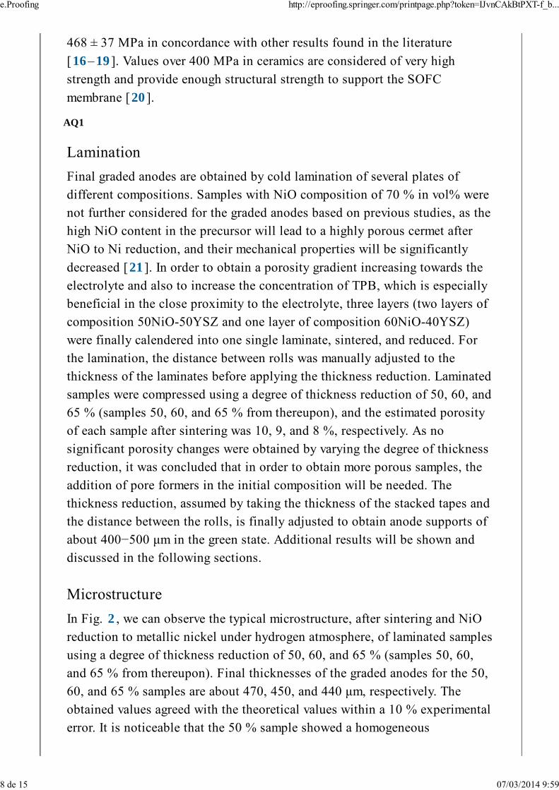
In Fig. 2 , we can observe the typical microstructure, after sintering and NiOreduction to metallic nickel under hydrogen atmosphere, of laminated samplesusing a degree of thickness reduction of 50, 60, and 65 % (samples 50, 60,and 65 % from thereupon). Final thicknesses of the graded anodes for the 50,
60, and 65 % samples are about 470, 450, and 440 μm, respectively. Theobtained values agreed with the theoretical values within a 10 % experimentalerror. It is noticeable that the 50 % sample showed a homogeneous
e.Proofing http://eproofing.springer.com/printpage.php?token=IJvnCAkBtPXT-f_b...
8 de 15 07/03/2014 9:59
distribution of pores along the thickness of the anode despite the differentcomposition of the first layer. The degree of thickness reduction seems to beinsufficient, confirmed by some defects between the layers, as noted in
Fig. 2a . However, the 60 % sample showed a clear transition between the two
different compositions (Fig. 2c ). However, some defects between layers were
still observed. Finally, the 65 % sample (Fig. 2e ) showed a good adhesion
between layers, and no defects were detected. In Fig. 3b, d, and f , we canobserve the typical microstructure of the anode, showing a homogeneous
distribution of pores, YSZ, and Ni metallic particles for the three samples. Asummary of the different values obtained by image analysis (and also by Hg
porosimetry as discussed in the next section) is shown in Table 2 .
e.Proofing http://eproofing.springer.com/printpage.php?token=IJvnCAkBtPXT-f_b...
9 de 15 07/03/2014 9:59
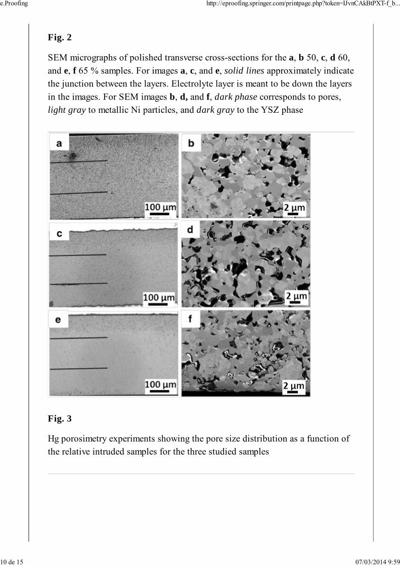
Fig. 2
SEM micrographs of polished transverse cross-sections for the a, b 50, c, d 60,
and e, f 65 % samples. For images a, c, and e, solid lines approximately indicatethe junction between the layers. Electrolyte layer is meant to be down the layers
in the images. For SEM images b, d, and f, dark phase corresponds to pores,
light gray to metallic Ni particles, and dark gray to the YSZ phase
Fig. 3
Hg porosimetry experiments showing the pore size distribution as a function ofthe relative intruded samples for the three studied samples
e.Proofing http://eproofing.springer.com/printpage.php?token=IJvnCAkBtPXT-f_b...
10 de 15 07/03/2014 9:59
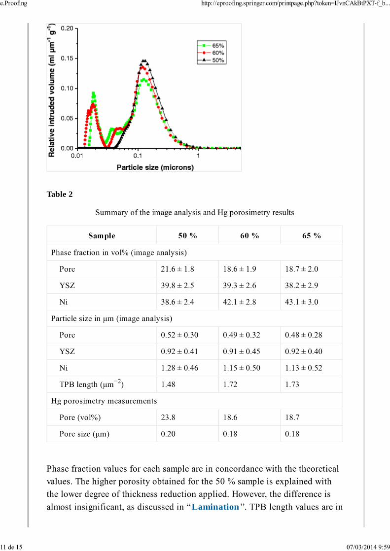
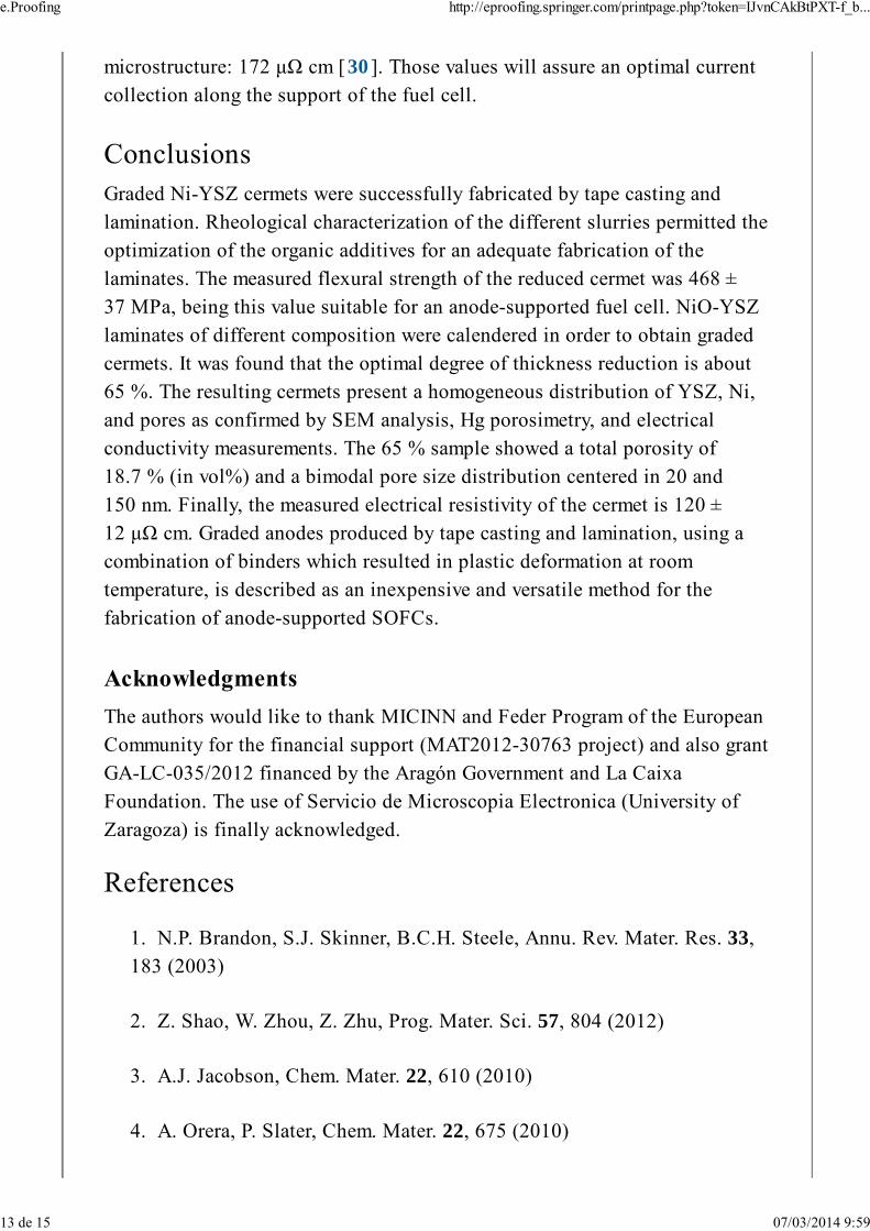
Table 2
Summary of the image analysis and Hg porosimetry results
Phase fraction in vol% (image analysis)
Pore 21.6 ± 1.8 18.6 ± 1.9 18.7 ± 2.0
YSZ 39.8 ± 2.5 39.3 ± 2.6 38.2 ± 2.9
Ni 38.6 ± 2.4 42.1 ± 2.8 43.1 ± 3.0
Particle size in μm (image analysis)
Pore 0.52 ± 0.30 0.49 ± 0.32 0.48 ± 0.28
YSZ 0.92 ± 0.41 0.91 ± 0.45 0.92 ± 0.40
Ni 1.28 ± 0.46 1.15 ± 0.50 1.13 ± 0.52
TPB length (μm ) 1.48 1.72 1.73
Hg porosimetry measurements
Pore (vol%) 23.8 18.6 18.7
Pore size (μm) 0.20 0.18 0.18
Phase fraction values for each sample are in concordance with the theoreticalvalues. The higher porosity obtained for the 50 % sample is explained withthe lower degree of thickness reduction applied. However, the difference is
almost insignificant, as discussed in “Lamination ”. TPB length values are in
−2
e.Proofing http://eproofing.springer.com/printpage.php?token=IJvnCAkBtPXT-f_b...
11 de 15 07/03/2014 9:59

good agreement with values reported by other authors (0.7–5.2 μm ) for
cermets containing particles of similar sizes [12 , 22 , 23 ].
Study of the pore size distribution is essential to assure an appropriate fueldistribution along the graded anode. For this purpose, the three studiedsamples were analyzed by Hg porosimetry. Total intruded porosity for the 50,60, and 65 % samples was 23.8, 18.6, and 18.7 % (in vol%), respectively, inconcordance with the results obtained by image analysis as discussed in
“Microstructure”. Those values are probably to some extent lower than thedesired porosity for an anode-supported cell, typically above 30 %, especiallyin the further region form the electrolyte. Even though the mechanicalproperties will be decreased in this further region, the addition of poreformers such as cornstarch is suggested in order to increase the porosity, as
demonstrated for tubular cells [24 ] and currently under study for these gradedanodes for planar cells. Normalized intruded pore size distribution is also
shown in Fig. 3 . The three samples present the majority of the pores centeredin a diameter of 100–200 nm. In addition, samples 60 and 65 % also presentadditional smaller pores ranging from 15 to 40 nm, whereas these pores arenot present in sample 50 %. Porosity of those small size ranges is typically
associated to NiO to Ni reduction of NiO nanoparticles [25 ] in the range of100 nm or less, which is about the minimum grain size detected by SEManalysis. As sample 50 % presented higher porosity (as observed in the SEM
micrographs of Fig. 2 and also shown in the Hg porosimetry experiments of
Fig. 3 ), NiO particle size could grow, especially during sintering and most
unlikely during NiO reduction, due to the Otwsald-ripening mechanism [26 ].
RT resistivity measurements were performed for the three samples using the dcfour-point technique. In these experiments, a current of 100 mA flows alongthe growth direction. The observed resistivity (mean value ± standarddeviation) are 126 ± 13 μΩ cm for the 50 % sample, 116 ± 12 μΩ cm for the60 % sample, and 120 ± 12 μΩ cm for the 65 % sample. For reference, the
bulk resistivity of the corresponding metallic nickel is 6.84 μΩ cm [27 ]. Inaddition, it is also remarkable that the measured resistivity values in Ni-YSZare lower than in other well-conducting Ni-YSZ cermets reported in the
literature of similar Ni content: 256 μΩ cm [28 ] or 833 μΩ cm [29 ] and alsoeven lower than a lamellar eutectic Ni-YSZ cermet with well-aligned
−2
e.Proofing http://eproofing.springer.com/printpage.php?token=IJvnCAkBtPXT-f_b...
12 de 15 07/03/2014 9:59
microstructure: 172 μΩ cm [30 ]. Those values will assure an optimal currentcollection along the support of the fuel cell.
Graded Ni-YSZ cermets were successfully fabricated by tape casting andlamination. Rheological characterization of the different slurries permitted theoptimization of the organic additives for an adequate fabrication of thelaminates. The measured flexural strength of the reduced cermet was 468 ± 37 MPa, being this value suitable for an anode-supported fuel cell. NiO-YSZlaminates of different composition were calendered in order to obtain gradedcermets. It was found that the optimal degree of thickness reduction is about65 %. The resulting cermets present a homogeneous distribution of YSZ, Ni,and pores as confirmed by SEM analysis, Hg porosimetry, and electricalconductivity measurements. The 65 % sample showed a total porosity of18.7 % (in vol%) and a bimodal pore size distribution centered in 20 and
150 nm. Finally, the measured electrical resistivity of the cermet is 120 ± 12 μΩ cm. Graded anodes produced by tape casting and lamination, using acombination of binders which resulted in plastic deformation at roomtemperature, is described as an inexpensive and versatile method for thefabrication of anode-supported SOFCs.
The authors would like to thank MICINN and Feder Program of the EuropeanCommunity for the financial support (MAT2012-30763 project) and also grantGA-LC-035/2012 financed by the Aragón Government and La CaixaFoundation. The use of Servicio de Microscopia Electronica (University of
Zaragoza) is finally acknowledged.
1. N.P. Brandon, S.J. Skinner, B.C.H. Steele, Annu. Rev. Mater. Res. 33,183 (2003)
2. Z. Shao, W. Zhou, Z. Zhu, Prog. Mater. Sci. 57, 804 (2012)
3. A.J. Jacobson, Chem. Mater. 22, 610 (2010)
4. A. Orera, P. Slater, Chem. Mater. 22, 675 (2010)
e.Proofing http://eproofing.springer.com/printpage.php?token=IJvnCAkBtPXT-f_b...
13 de 15 07/03/2014 9:59
5. M.A. Laguna-Bercero, J. Power Sources 203, 4 (2012)
6. L.H. Luo, A.I.Y. Tok, F.Y.C. Boey, Mater. Sci. Eng. A Struct. 429, 267(2006)
7. E. Ozel, S. Kurama, J. Mater. Process. Technol. 198, 69 (2008)
8. S.B. Savignat, M. Chiron, C. Barthet, J. Eur. Ceram. Soc. 27, 674(2007)
9. H. Moon, S.D. Kim, S.H. Hyun, H.S. Kim, Int. J. Hydrogen Energy 33,1758 (2008)
10. H. Park, H. Moon, S.C. Park, J.J. Lee, D. Yoon, S.H. Hyun, D.H. Kim,
J. Power Sources 195, 2463 (2010)
11. X. Li, J. Lu, H. Wang, Sci. Sinter. 43, 305 (2011)
12. A. Faes, A. Hessler-Wyser, D. Presvytes, C.G. Vayenas, J. Van Herle,
Fuel Cells 9, 841 (2009)
13. J. Gurauskis, D. Sola, J.I. Peña, V.M. Orera, J. Eur. Ceram. Soc. 28,
2673 (2008)
14. R. Moreno, Reología de suspensiones cerámicas (rheology of ceramicsuspensions) (Consejo Superior de Investigaciones Científicas, Madrid,2005)
15. R.E. Mistler, E.R. Twiname, Tape casting theory and practice (Wiley& The American Ceramic Society, Westerville, 2000)
16. A. Nakajo, J. Kübler, A. Faes, U. Vogt, H. Schindler, L.K. Chiang, S.
Modena, J. Van Herle, T. Hocker, Ceram. Int. 38, 3907 (2012)
17. Y. Wang, M.E. Walter, K. Sabolsky, M.M. Seabaug, Solid State Ionics
177, 1517 (2006)
18. M. Radovic, E. Lara-Curzio, Acta Mater. 50, 5747 (2004)
19. A. Atkinson, A. Selcuk, Solid State Ionics 134, 59 (2000)
e.Proofing http://eproofing.springer.com/printpage.php?token=IJvnCAkBtPXT-f_b...
14 de 15 07/03/2014 9:59
20. R.W. Cahn, P. Haasen, E.J. Kramer, in Materials science andtechnology, a comprehensive treatment: processing of ceramics part 1,vol. 17 A, ed. by R.J. Brook (VCH, Weinheim, 1996)
21. S. Biswas, T. Nithyanantham, S.N. Thangavel, S. Bandopadhyay,
Ceram. Int. 39, 3103 (2013)
22. J.R. Wilson, W. Kobsiriphat, R. Mendoza, H.Y. Chen, J.M. Hiller, D.J.Miller, K. Thornton, P.W. Voorhees, S.B. Adler, S.A. Barnett, Nat. Mater.
5, 541 (2006)
23. B. Kenney, M. Valdmanis, C. Baker, J.G. Pharoah, K. Karan, J. Power
Sources 189, 1051 (2009)
24. M.A. Laguna-Bercero, R. Campana, A. Larrea, J.A. Kilner, V.M.
Orera, J. Electrochem. Soc. 6, B852 (2010)
25. J.A. Medford, A.C. Johnston-Peck, J.B. Tracy, Nanoscale 5, 155(2013)
26. J.M. Howe, Interfaces in materials: atomic structure, thermodynamicsand kinetics of solid-vapor, solid-liquid and solid-solid interfaces, cap. 4,surface structure (Wiley, New York, 1997), p. 113
27. Handbook of Chemistry and Physics, 55th edn. (CRC Press, Inc.,1974)
AQ2
28. D. Simwonis, F. Tietz, D. Stöver, Solid State Ionics 132, 241 (2000)
29. D. Skamoutsos, A. Tsoga, A. Naoumidis, P. Nikolopoulos, Solid State
Ionics 135, 439 (2000)
30. M.A. Laguna-Bercero, A. Larrea, J.I. Peña, R.I. Merino, V.M. Orera, J.
Eur. Ceram. Soc. 25, 1455 (2005)
e.Proofing http://eproofing.springer.com/printpage.php?token=IJvnCAkBtPXT-f_b...
15 de 15 07/03/2014 9:59