environmental results program certification workbook
TRANSCRIPT

Environmental Results Program
Certification Workbook
For
Underground Storage Tank Facilities
February 2019
State of Rhode Island Department of Environmental Management
Office of Waste Management, UST Program & Office of Customer and Technical Assistance
235 Promenade Street Providence, RI 02908
(401) 222-4700
http://www.dem.ri.gov/

Table of Contents
1. Should You Use This Workbook? ............................................. 1
2. Introduction ........................................................................................ 3 2.1 What is the Purpose of this Workbook? .................................... 3
2.2 Legislative Authority ................................................................. 3 2.3 What is the Environmental Results Program? ........................... 3 2.4 Why Participating in the UST ERP is Important ........................ 4 2.5 What It Means to Be in Compliance .......................................... 4
3. How to Use This Workbook..............................................................6 3.1 Organization of the Workbook? ................................................ 6
3.2 Organization of Chapter ............................................................. 7 3.3 Steps for Reviewing Each Section in Chapter 4.........................7 3.4 Example: Joe and the A&B Gas Station . . … . . .........................8
4. Regulatory Requirements and Best Management Practices at Your Facility ................................................................................15
4.1 Spill Protection ..................................................................17
4.2 Correct Filling Practices ....................................................19
4.3 Overfill Prevention .............................................................21 4.3.1 Overfill Alarms .................................................................................... 24 4.3.2 Automatic Shutoff Devices ................................................................. 25 4.3.3 Tanks with Ball Float Valves (also called Float Vent Valves) ............ 25 4.3.4 Vent Alarms ....................................................................................... 26 4.3.5 No Overfill Prevention ........................................................................ 27
4.4 Corrosion Protection for Tanks ........................................ 28 4.4.1 Fiberglass Reinforced Plastic (FRP) Tanks, Jacketed Steel Tanks, and
Clad Steel Tanks ................................................................................ 30 4.4.2 Coated and Cathodically Protected Steel Tanks ............................... 31 4.4.3 Cathodically Protected Steel Tanks ................................................... 32 4.4.4 Internally-Lined Steel Tanks .............................................................. 33 4.4.5 Internally-Lined and Cathodically Protected Steel Tanks .................. 35 4.4.6 Steel Tanks with No Additional Corrosion Protection ........................ 37
4.5 Corrosion Protection for Piping ........................................ 38 4.5.1 Fiberglass Reinforced Plastic (FRP) Piping and Flexible Plastic
Piping .................................................................................................. 41 4.5.2 Coated and Cathodically Protected Steel Piping ................................ 42 4.5.3 Cathodically Protected Metal Piping (Other than Steel) ..................... 43 4.5.4 Metal Piping - No Additional Corrosion Protection ............................. 44
Contents i

4.6 Cathodic Protection ......................................................... 45 4.7 Leak Detection for Tanks ................................................ 50
4.7.1 Automatic Tank Gauging (ATG) ............................................................. 55 4.7.2 Interstitial Monitoring for Double-Walled Tanks ..................................... 57 4.7.3 Tightness Testing for Single-Walled Tanks............................................... 59 4.7.4 Tightness Testing for Double-Walled Tanks...............................................60 4.7.4.1 Exemption for “Brine” Interstitial Tanks………………………………61 4.7.5 Inventory Control ..................................................................................... 62 4.7.6 Inventory Control for Single-Walled Waste oil and motor oil Tanks Less Than 2,000 Gallons ................................................................................ 64
4.8 Leak Detection for Piping ................................................ 67 4.8.1 Pressurized Piping ................................................................................. 69
4.8.1.1 Automatic Line Leak Detectors (LLDs) .......................................... 71 4.8.2 Suction Piping ........................................................................................ 72 4.8.3 Tightness Testing for Single-Walled Piping.......................................... 74 4.8.4 Tightness Testing for Double-Walled Piping......................................... 75
4.9 What To Do For Suspected and Confirmed Releases .... 77 4.10 Financial Responsibility .................................................. 79
4.11 Temporarily Closed UST Systems .................................. 84
4.12 Groundwater Monitoring & Tank Pad Observation Wells 86 4.12.1.1 Construction Standards & Maintenance Requirement..................86
4.13 Mandatory Deadline for Permanent Closure of Single-Walled UST Systems (Tanks and/or Piping).......................88
4.14 Delivery Prohibition ........................................................... 88
4.15 Operator Training .............................................................. 90 4.15.1 Operator Training and Certification ........................................................ 92
4.15.1.1 Retraining and Re-Certification .....................................................93 4.15.2 Inspections and Maintenance ................................................................. 93 4.15.3 Record Keeping....................................................................................... 94
5. Stage I Vapor Recovery Systems 5.1 Stage I Vapor Recovery .................................................. 95
5.1.1 Overview – Stage I.................................................................................. 95 5.1.2 Rhode Island Regulations .......................................................................99 5.1.3 Requirements ..........................................................................................99
5.1.3.1 Exemptions ...................................................................................100 5.1.3.2 Control Systems ...........................................................................100 5.1.3.3 Gasoline Storage Vessel (Tank) Requirements, Gasoline Delivery Vessel (Cargo Tank) Requirements ............................................ 101 5.1.3.4 Operators of Gasoline Dispensing Facilities .................................101 5.1.3.5 Records..........................................................................................102 5.1.3. 6 Compliance & Compliance Test Methods .................................... 102
5.1.4 Stage I Weekly Inspection Information .................................................102 5.1.5 Stage I Vapor Recovery Components ..................................................103
ii Contents

Appendices A. For More Information B. Sample Placards for Overfill Devices C. Sample Emergency Numbers List D. Cathodic Protection Testing Form E. Impressed Current 60 Day Inspection Form F. Sample 30-Day Release Detection Monitoring Record G. Sample Daily and Monthly Inventory Worksheets H. Manual Tank Gauging Record for Waste Oil or Motor Oil Tanks Less than 2,000 Gallons I. Registration Form
J. Transfer of Certification of Registration Form K. Operator’s Monthly Inspection Checklist L. Chart of Typical Ongoing Testing Requirements for UST Systems
iii Contents
Chapter 1
1
Chapter 1: Should You Use This Workbook? This Workbook is designed to help owners and operators of underground storage tanks (commonly referred to as USTs) with the Rules and Regulations for Underground Storage Facilities Used for Regulated Substances and Hazardous Materials, effective November 20, 2018. The Workbook describes requirements and best management practices (BMPs) for your UST system and helps you to determine whether your underground storage tanks are in compliance with the regulations.
The DEM has developed and implemented an Environmental Results Program (ERP). If
you have underground storage tanks at your facility that meet the criteria described on
the following page, you must read and fill out the checklist questions that accompany
this Workbook. If, after reading this section, you determine that the Workbook does not
apply to you, fill out the Non-Applicability Statement included in the accompanying
forms booklet and send it to the DEM. This will inform the DEM that you do not have any UST systems that fall under this program.
For each UST system that you operate, you are required to complete and submit the Compliance Certification Checklist and Certification Statement (and, if required, a Return to Compliance Plan form) and return these forms to the DEM. The Compliance Certification Checklist, Statement, and Return to Compliance Plan forms are included in the accompanying Forms Booklet. As part of the UST ERP program, the DEM will conduct random and targeted inspections. If you do not meet the above requirements, you will be targeted. Carefully review this Workbook to make sure that you understand the requirements you must meet and that you are able to accurately fill out the Compliance Certification Checklist, Certification Statement, and the Return to Compliance Plan forms.
To determine whether you must complete the required UST ERP Certification forms: • Read and answer the question in this chapter. • Use the information below the question to help you answer the question. • Follow the directions in the gray box below the question.

2
Chapter 1
How many UST systems at your facility meet at least one of the following criteria? These are types of UST systems covered by this Workbook.
Number of USTs
• Contains hazardous materials Examples:
a) contain regulated substances* or used oil (destined for recycling) at public gasoline stations or repair shops
b) private regulated substances tanks used for fueling of business vehicles (for example: bus terminals)
c) store fuel for use by emergency power generators * The term “regulated substance” includes but is not limited to petroleum and petroleum-based substances comprised of a complex blend of hydrocarbons, such as motor fuels, jet fuels, distillate fuel oils, residual fuel oils, lubricants, petroleum solvents, and used oils.
• If you have at least one UST system that meets the criteria above, complete the applicable portions of the Compliance Certification Checklist and Forms Booklet. Please note the list of exemptions below.
• If you have no UST systems that meet the criteria above, you do not have any UST systems covered by the Environmental Results Program. This workbook does not apply to you. Fill out the Non-Applicability Statement included in the accompanying Forms Booklet and send it to the
DEM.
Exempt UST Systems: An UST system that meets at least one of the criteria below is an
exception to the UST systems you identified above and is not covered by the UST ERP. If you received this Workbook, it would be uncommon for all of your tanks to meet at least one of the criteria below.
Types and use of tanks • Hydraulic lift tanks • Storage tanks located entirely within structures, such as a basement or cellar provided that:
a) The structure allows for physical access to the storage tank b) The structure is not part of a secondary enclosure; and c) The tank is situated upon or above the surface of a concrete floor
• Septic tanks • Pipeline facilities regulated under the Natural Gas Pipeline Safety Act of 1968 or the Hazardous
Liquid Pipeline Safety Act of 1979 • Flow through process tanks • USTs storing propane or liquified or natural gas • USTs used for the temporary storage of raw materials or products by industry (so called
“Intermittent” or “fill and draw” tanks) • Emergency spill protection or overflow tanks • USTs connected to floor drains or other piping outlets which serve residential structures of a 1, 2,
or 3 family dwelling • Oil water separators with a planned discharge required to be regulated under the Clean Water Act • Residential tanks < or = 1,100 gallons in capacity used for storing #2 heating oil serving a 1, 2, or 3
family dwelling • farm tanks < 1,100 gallons in capacity and storing #2 heating oil for non-commercial purposes
If you are still not sure whether the UST ERP applies to you, call the DEM at (401) 222-2797. You may face substantial penalties if you intentionally falsify your applicability. The DEM will be checking your responses for accuracy.

Chapter 2 3
Chapter 2: Introduction 2.1 What is the Purpose of this Workbook? This Workbook is designed to:
• Clearly explain the environmental, record keeping, and compliance requirements and best
management practices that apply to UST systems; and • Assist owners and operators of regulated UST systems in Rhode Island to participate in the
ERP.
2.2 Legislative Authority
Rhode Island law requires UST system owner/operators who answered “Yes” to the question in the previous chapter to comply with the RI DEM UST ERP. These owner/operators are required to complete and submit the applicable checklist questions in the accompanying Forms Booklet, complete and submit the Compliance Certification Statement, and, if necessary, complete and submit a Return to Compliance Plan(s) for any aspects of their UST system(s) that are determined to be out of compliance.
2.3 What is the Environmental Results Program?
The Environmental Results Program (ERP) is a common sense approach to achieving environmental protection. It was first developed and used successfully by Massachusetts in 1997. The DEM believes that the ERP will assist UST system owners and operators in understanding and complying with UST system regulations and lead to exceeding environmental standards. The ERP gives you the information to understand the maintenance and operational requirements that pertain to your UST system while improving accountability to the public for environmental performance.
Rhode Island’s Environmental Results Program includes:
• This Workbook which includes best management practices and compliance requirements.
The Workbook has a direct relation to the Compliance Certification forms mentioned below;
• A Compliance Certification Checklist of questions that are required to be completed by
the owner/operator. This checklist is included in the accompanying Forms Booklet;
• A Certification Statement form that UST system owners and operators are required to
complete, sign, and return to the DEM. On the form, the UST system owners and operators must certify the current compliance status of the facility and acknowledge that the facility must comply with all applicable environmental laws. This form is included in the accompanying forms booklet;
• a Return to Compliance Plan form which is used for compliance problems identified in the
process of filling out the Compliance Certification Checklist and that cannot be corrected prior to submittal of the certification forms. The Return to Compliance Plan describes what

Chapter 2 4
steps the facility will take to meet its requirements and when it will return to full compliance. This form is included in the accompanying Forms Booklet;
• Workshops so owners and operators can learn about their responsibilities under ERP;
• Audits/inspections to confirm the accuracy of the certifications and compliance with the
UST system regulations; and • Technical assistance, which is available online at
http://www.dem.ri.gov/programs/customertech/ust-environmental-results.php, by phone at (401) 222-2797 or by e-mail by contacting Kevin Gillen at [email protected]
2.4 Why Participating in the UST ERP is Important As an UST system owner or operator, you have an important role to play in protecting public health, the environment, and your economic investment. If UST systems are not operated and maintained properly, they could leak and pollute the environment. An ERP is an approach that will help you comply with UST system regulations, which will in turn help protect public health, the environment, and your economic investment.
• Public health and the environment: Releases from UST systems (spills, overfills, leaking
tanks and piping) can contaminate groundwater, soil, surface water, air, etc. Approximately 50 percent of Americans depend on groundwater consumption. In addition, leaks can result in fires or explosions, which threaten human safety.
• Economic investment: It is important to quickly detect and report releases, as required by
UST regulations. Any product that is lost in a release may cost you in terms of cleanup costs, potential penalties, and the lost revenue of product not sold. By responding quickly and containing a release, you may be able to reduce cleanup costs and environmental damage.
2.5 What It Means to Be in Compliance To be in compliance means you meet the minimum DEM requirements for your UST system. You must meet all environmental requirements for each regulated UST system to be in compliance1. The UST system requirements include spill, overfill, corrosion protection, release detection, financial responsibility, proper installation, correct operation, maintenance, repair, testing, controlling releases, reporting releases, remediating releases, reporting and record- keeping, temporary closure, and permanent closure.
1While this Workbook addresses most RI DEM environmental requirements that apply to UST systems, your
facility may need to meet additional requirements that are not covered in this Workbook or in the UST ERP. For example, requirements related to Class V injection wells (motor vehicle waste disposal wells such as a gas station with a service floor drain that leads to a septic system), aboveground storage tanks, hazardous substances, used tires, and other requirements may apply to your facility as well. Also, this Workbook does not address liability for pollution or spills that may have occurred on your property in the past. If you are unsure whether additional requirements apply to your facility, please call RI DEM at (401) 222-2797.

Chapter 2 5
If you are the owner or operator of one or more UST systems, there are certain things you MUST
do by law to protect human health and the environment. You are responsible for preventing and quickly detecting releases from your UST systems. You are also responsible for reporting and cleaning up any releases that occur. You will be held accountable if your UST system(s) leak. Therefore, you should do everything in your ability to ensure releases do not occur.
For further regulatory information, see either of the following: The Federal UST regulations, 40 Code of Federal Regulations Part 280, are located at:
https://www.epa.gov/ust/revising-underground-storage-tank-regulations-revisions-existing-requirements-and-new
The DEM UST regulations are located at:
https://rules.sos.ri.gov/regulations/part/250-140-25-1

This Page Intentionally Left Blank
Chapter 3 6
Chapter 3: How to Use This Workbook
Read this chapter to learn how to use this Workbook. This chapter will tell you:
• What kind of information is contained in the rest of the Workbook, • How that information is organized, • How to work through Chapters 4 and 5, • How a facility would fill out a section of Chapter 4 or 5, and • What the symbols mean in Chapters 4 and 5.
3.1 Organization of the Workbook
You have already read Chapter 1 and Chapter 2. Chapter 1 showed you that you have at least one regulated UST system, and that you need to complete and submit the questions that accompany this Workbook and complete and submit Compliance Certification forms to the DEM (and, if required, a Return to Compliance Plan form). Chapter 2 explained what the ERP is and why it is important to comply with regulations. This chapter will help you understand the rest of the Workbook. After Chapter 3, there are three major parts of the Workbook:
Chapter 4: Regulatory Requirements and Best Management Practices at Your Facility Chapter 4 will help you understand what you have to do to comply with UST regulations and to improve the environmental performance of your facility. You should review the material in Chapter 4 so that you will know how to complete the Compliance Certification Checklist and Certification Statement that you will need to send to the DEM.
Do not be worried by the size of Chapter 4. Most likely, only some parts of the sections in Chapter 4 will apply to your facility. You should review all sections that apply to your UST system(s) but you do not need to review the work if part of the section does not apply to your UST system(s). Each section in Chapter 4 will help you easily decide whether you should review the parts of that section.
Chapter 5: Stage I and Stage II Vapor Recovery System Requirements Chapter 5 will help you understand what you have to do to comply with the Stage I and Stage II vapor recovery system regulations and to improve the environmental performance of your facility.
Appendices The appendices contain information to help you understand the Workbook and comply with the regulations. They include forms and checklists that can help you stay in compliance. Appendix A also provides a list of UST program contacts and other resources that can help answer your questions.
In addition, the front and back covers of this Workbook contain other important information to review: • The inside front cover has a guide you can use to do periodic walk-through inspections; and • The inside back cover lists activities you need to do, even after finishing the Workbook.

Chapter 3 7
3.2 Organization of Chapter 4 Chapter 4 will help you understand environmental requirements that apply to your facility. The beginning of Chapter 4 has a table for you to identify UST systems at your facility. You will use this information when reviewing the checklists and tables in Sections 4.1 through 4.15. Each of those sections covers a different part of the UST system requirements. You must review each of the 15 sections in Chapter 4 to see if they apply to your facility. Following your review of the sections, complete the Compliance Certification Checklist, Certification Statement, and any necessary Return to Compliance Plan forms found in the Forms Booklet that accompanies this Workbook.
Sections 4.1 through 4.15 contain: • Information on determining which compliance option your UST system uses to meet the
requirements in that section, • A table for you to identify the compliance options each UST system uses, • lists of requirements and best management practices for each option, • Compliance checklist questions similar to those you must fill out in the accompanying Forms
Booklet for each compliance option that your UST system(s) use, • Summary of compliance questions for all UST systems at your facility, and •Information about the UST Operator Training program.
3.3 Steps for Reviewing Each Section in Chapter 4
DIRECTIONS: Important directions are provided in gray boxes like this one. Read all directions! There will be specific directions to follow in each section of Chapter 4 that tell you how to proceed through that section. Below are the steps for completing a thorough review of Chapter 4. The example in the next section shows how one facility followed these directions to complete the section on overfill prevention.
The steps for completing each section in Chapter 4 are as follows: 1. Read the beginning of each section to understand if it applies to your facility. If you are sure
it does not apply, you can skip the section. If it does apply, you should review the questions associated with the section. The section may ask you to fill out a table to identify which compliance options are used by each of your UST systems. This table will help you understand how to complete the Compliance Certification Checklist questions associated with each section. Use the UST identification table at the beginning of Chapter 4 to keep track of the UST systems at your facility.
2. Read the information on requirements and best management practices (BMP) contained in
each section. Then work on the checklists in each section as follows: • Circle the “UST #” at the top of the checklist for each UST system that uses the option or
meets the characteristics of this checklist. • Answer the questions in the checklist for UST systems that you circled at the top. Circle
“Y” for yes or “N” for no in the column below each UST that you circled. Leave all questions blank for USTs that you did not circle. Skip a question only if you are told to do so.
• Notice that sometimes a question will tell you to complete a different section first to get the answer for the question. When you do the other section, be sure to come back!
• Transfer your answers for the Workbook questions to the applicable portion of the Compliance Certification Checklist provided in the accompanying Forms Booklet. The questions in the Forms Booklet are similar to the questions provided throughout Chapter 4 of this ERP Workbook.

Chapter 3 8
Note: If you prefer to answer the Compliance Certification Checklist questions in the Forms Booklet directly, without first reviewing and completing the information in this Workbook, you may do so. The Workbook and the accompanying checklist questions are organized to allow you to use this Workbook as a reference when completing the Compliance Certification Checklist questions.
3. Answer the final summary of compliance question for your facility on the last page of many
longer sections (like Section 4.3). The final summary of compliance question asks whether all of your UST systems are in compliance with the major set of requirements discussed in that section. If you answered no to any compliance questions in a section, you must answer no to this summary of compliance question and complete a Return to Compliance Plan form provided in the Forms Booklet.
You will use the answers to the questions in Chapter 4 to complete your Compliance Certification Checklist, Certification Statement and, if necessary, Return to Compliance Plan form(s). Follow the instructions provided in the Forms Booklet to fill those forms out.
3.4 Example: Joe and the A&B Gas Station
The next few pages tell the story of Joe, the owner of a gas station, and how he filled out a few parts of Chapter 4 in this Workbook. Joe is not a real person, but we made up his story to help you understand how to begin to fill out the information in Chapter 4. Joe’s story does not tell you everything he did to fill out Chapter 4, but his story will help you get started on the right foot.
Joe’s example is explained in dark, bold letters over the next few pages. Try to read the whole story, because it will help you understand how to:
(1) Fill out the tables in Chapter 4, (2) Complete the compliance checklists in Chapter 4, (3) Answer the summary of compliance question in Chapter 4, and (4) Fill out the Compliance Certification Checklist, Certification Statement and, if necessary, Return to Compliance Plan form(s) provided in the Forms Booklet.
Joe’s story begins here...
Joe is the owner of A&B Gas Station on the corner of Elm and Main Streets. He also
owns Y&Z Gas on the corner of Maple and State Streets. Joe is filling out this Workbook only for A&B Gas. He will use the information he writes in the Workbook to correctly fill out his checklist questions and his ERP Certification of Compliance form for A&B Gas. He will fill out a separate checklist and a Certification of Compliance form for Y&Z Gas.
Joe received the Workbook in the mail and starts working on the Workbook a little bit at a time. He knows that starting early will help make sure he has time to collect the right
information and do everything the right way before the deadline.
Joe has three underground storage tank (UST) systems at A&B Gas. One UST holds gasoline, one holds kerosene, and one holds used oil. The gasoline UST is
“compartmentalized.” This means the tank is divided into different sections or compartments. (Usually, each compartment will have a different product in it.) This tank has a compartment for regular gasoline and a compartment for premium gasoline.
The three tanks are lined up in a row from east to west. Joe usually calls the gasoline tank the “east tank.” He calls the kerosene tank the “middle tank” and the used oil tank

Chapter 3
9
the “west tank.” Joe’s kerosene tank is a lot older than his other two tanks, so he does not know as much about that tank as he does about the gasoline tank and the used oil tank.
To start, Joe reads Chapters 1, 2, and 3. When he is done, he feels he has a pretty good idea of how to fill out the Workbook, so he turns to Chapter 4.
Joe Identifies the USTs at His Facility
Before Joe can begin filling out any of the questions in Chapter 4, he has to fill out the
table at the beginning of Chapter 4 that helps him keep track of the tanks he has. He will use the numbers that he gives to each tank in this table (1-5) to identify them in the rest of Chapter 4. He follows the directions in the Workbook to put descriptive information for each tank into the table. You can see a copy of Joe’s completed table at the bottom of this page.
Even though the premium and regular gas are stored in the same tank, the directions tell him to enter each compartment as a separate UST. So Joe calls the premium section of his gasoline tank “UST 1”. Joe knows the registration number of this tank, so he puts that in the “Identification Number” column. Joe fills in the type of product contained in
this compartment and the size of the compartment. In the column called “Other UST Identification Information” Joe writes that this tank is the east tank, since that is how he thinks of it.
Joe calls the regular compartment of the gasoline tank “UST 2” and fills in the registration number and location. These are the same as for the premium compartment. He also fills in the size of this compartment and the type of product it holds.
Joe calls his kerosene tank “UST 3”. He does not know this tank’s registration number, so he leaves that blank. He writes in the type of product and size, and that this is the middle tank.
Joe calls the used oil tank “UST 4” and fills in the information for this tank. He calls this tank the west tank.
Joe has a total of four USTs (since the premium and regular gasoline compartments
count separately). So he does not put anything in the fifth row of the table.
UST Identification Table
UST Number
Identification
Number Type of Product Tank Info.
(Single-wall, Double-wall, Lining, etc.)
Piping Info. (Single-wall, Double-wall, Lining, etc.)
Tank
Material Size
(Gallons) Other
Identifying Information
1 00123 Premium Double Single Steel 4,000 East
2 00123 Regular Double Single Steel 6,000 East
3 Kerosene Single Double Steel 2,000 Middle
4 00012 Used Oil 1,000 West
5
Now that Joe has identified all of his USTs, he is ready to look at the other sections in Chapter 4. Joe reads the directions and fills out Sections 4.1 and 4.2. He did not have

Chapter 3
10
much trouble with these sections since he read the directions. We join Joe again when he starts Section 4.3. This section is a lot like the other sections in the workbook, so seeing how Joe fills it out will help you.
Joe Identifies the Types of Overfill Prevention He Has Joe is not exactly sure what to do when he starts Section 4.3, so he first reads the beginning of 4.3. He learns that overfill prevention is equipment on USTs to prevent tanks from overflowing when they are being filled. He also learns that most USTs have to have at least one type of overfill prevention to be in compliance.
Joe sees that there are three kinds of overfill prevention that the regulations allow: overfill alarms, ball float valves, and automatic shutoff devices. An overfill alarm goes off when a tank is close to being full, and can be seen and/or heard by the delivery person. An automatic shutoff device is located at the fill pipe of a tank, and it stops
product from flowing into a tank that is close to being full. A ball float valve is located inside a tank, and also slows down any product flowing into a tank that is almost full.
Joe already knows that he has an alarm for his gasoline tank. The information at the
beginning of 4.3 helps him figure out that he has an automatic shutoff device on his kerosene tank and no overfill prevention for his used oil tank.
At the beginning of Section 4.3, Joe fills out a table that asks about the kind of overfill
prevention that each of his USTs has. This table tells him which checklists in 4.3 he needs to fill out. A copy of Joe’s table is at the bottom of this page.
Using the UST numbers from the table he filled out at the beginning of Chapter 4 (shown
on the previous page of this story), Joe marks that USTs 1 and 2 have overfill alarms. (Remember that Joe has to think of each section of his gasoline tank as a separate UST.) He also marks that UST 3 (his kerosene tank) has an automatic shutoff device, and UST 4 (his used oil tank) has no overfill prevention. From this table, he sees that he has to fill out checklists in Sections 4.3.1, 4.3.2, and 4.3.5. He will fill these checklists out next. None of Joe’s USTs have ball float valves or vent alarms, so he can skip Section 4.3.3 and
4.3.4.
Choose the types of overfill prevention used for each tank by
checking the appropriate boxes
Go to these sections
for information and compliance checklists
UST Number: 1 2 3 4 5
Overfill Alarm X X Section 4.3.1
Automatic Shutoff Device X Section 4.3.2
Ball Float Valve Section 4.3.3
Vent Alarm Section 4.3.4
No Overfill Prevention X Section 4.3.5

Chapter 3
11
Joe Completes the Overfill Alarm Section for His Gasoline Tank Joe knows he needs to fill out Section 4.3.1 because Joe’s USTs 1 and 2 have overfill alarms and the table at the beginning of 4.3 directed him to Section 4.3.1. Joe turns to
Section 4.3.1 and reads about the requirements and best management practices for USTs with overfill alarms. Using that information, he answers the questions in this checklist.
A copy of Joe’s answers to the questions in Section 4.3.1 is provided here so that you can follow along. The next few paragraphs will tell you why he answered the questions the way he did.
At the top of the checklist, he circles the numbers 1 and 2 to show that these two tanks have overfill alarms. He will not answer any questions on this checklist for USTs 3 and 4, since they do not have overfill alarms.
Joe recently had a technician check his overfill alarms, so he knows that they are working according to the requirements he sees in the workbook. He answers yes for both tanks to Questions 1 and 2.
Joe’s Overfill Prevention Checklist for USTs with Overfill Alarms
Circle the UST number for each UST that has an overfill alarm. Fill out the questions below for each
UST you circled.
UST # =
1 2 3 4 5
Questions Yes (Y) or No (N)
1. Does your overfill alarm activate at 90% of tank capacity? 1 Y
1 N
2 Y
2 N
3 Y
3 N
4 Y
4 N
5 Y
5 N
If no, have a qualified person adjust your overfill device to the right height. Also, submit a Return to Compliance plan with your Certificate of Compliance.
2. Can your overfill alarm be seen and/or heard from the delivery location so that it will alert the delivery person that the tank is almost full?
1 Y
1 N
2 Y
2 N
3 Y
3 N
4 Y
4 N
5 Y
5 N
If no, have a qualified person fix your overfill alarm so that it can be heard and/or seen from the delivery location. Also, submit a Return to Compliance plan with your Certificate of Compliance.

Chapter 3
12
Joe Completes the Automatic Shutoff Device Section for His Kerosene
Tank
Joe knows that he needs to fill out Section 4.3.2 since the table at the beginning of 4.3 told him to fill out this section for his kerosene tank, which has an automatic shutoff
device. He reads the information about automatic shutoff devices before he answers the questions. The questions about automatic shutoff devices are like the questions Joe answered about overfill alarms.
A copy of Joe’s answer to the question in Section 4.3.2 is provided here so that you can follow along. The next few paragraphs will tell you why he answered the question the way he did.
Joe starts by circling UST 3 at the top of the checklist, since that is the only tank he has with an automatic shutoff device. He does not circle the other tanks, and will not answer any questions for them.
Joe’s kerosene tank overflowed when it was being filled last month. So Joe does not think his automatic shutoff device is working, and circles “no” for the applicable question. He sees that he will have to have a qualified person fix his automatic shutoff device so that he can be in compliance with the requirements for automatic shutoff devices.
In addition to having a qualified person fix his automatic shutoff device, Joe reads the directions that tell him he must submit a Return to Compliance Plan and submit this with his Certification of Compliance. Since Joe answered “no” to this question, he must
answer “no” to the summary of compliance question at the end of Section 4.3. He fills out a Return to Compliance Plan form included in his forms booklet. The Return to Compliance Plan tells the DEM how and when Joe will fix the problem. Joe will submit the Return to Compliance Plan with his ERP Certification of Compliance form.
Since Joe does not have any tanks with a ball float valve, the table at the beginning of Section 4.3 tells him he can skip Section 4.3.3. So he turns to Section 4.3.5 next to answer questions for his tank with no overfill prevention.
Joe’s Overfill Prevention Checklist for USTs with Automatic Shutoff
Devices
Circle the UST number for each UST that has an overfill alarm.
Fill out the questions below for each UST you circled.
UST # =
1 2 3 4 5
Questions Yes (Y) or No (N)
Does your automatic shutoff device properly activate at 95% of tank capacity or before the fittings at the top of the tank are exposed to fuel?
1 Y
1 N
2 Y
2 N
3 Y
3 N
4 Y
4 N
5 Y
5 N
If no, have a qualified person adjust your automatic shutoff device to properly activate at 95% of the tank capacity or before the fittings at the top of the tank are exposed to fuel. In addition, fill out a Return to Compliance plan and submit it with your Certification of Compliance.
Chapter 3
13
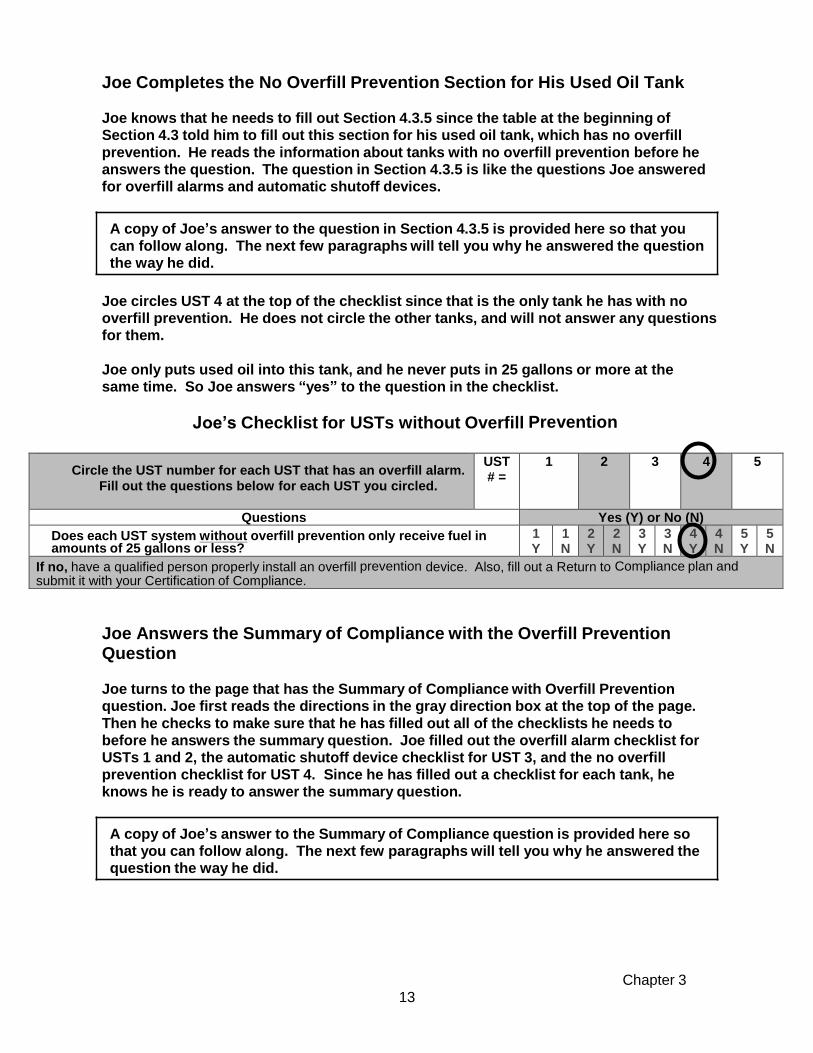
Joe Completes the No Overfill Prevention Section for His Used Oil Tank Joe knows that he needs to fill out Section 4.3.5 since the table at the beginning of Section 4.3 told him to fill out this section for his used oil tank, which has no overfill
prevention. He reads the information about tanks with no overfill prevention before he answers the question. The question in Section 4.3.5 is like the questions Joe answered for overfill alarms and automatic shutoff devices.
A copy of Joe’s answer to the question in Section 4.3.5 is provided here so that you can follow along. The next few paragraphs will tell you why he answered the question the way he did.
Joe circles UST 4 at the top of the checklist since that is the only tank he has with no overfill prevention. He does not circle the other tanks, and will not answer any questions for them.
Joe only puts used oil into this tank, and he never puts in 25 gallons or more at the same time. So Joe answers “yes” to the question in the checklist.
Joe’s Checklist for USTs without Overfill Prevention
Circle the UST number for each UST that has an overfill alarm.
Fill out the questions below for each UST you circled.
UST # =
1 2 3 4 5
Questions Yes (Y) or No (N)
Does each UST system without overfill prevention only receive fuel in amounts of 25 gallons or less?
1 Y
1 N
2 Y
2 N
3 Y
3 N
4 Y
4 N
5 Y
5 N
If no, have a qualified person properly install an overfill prevention device. Also, fill out a Return to Compliance plan and submit it with your Certification of Compliance.
Joe Answers the Summary of Compliance with the Overfill Prevention Question
Joe turns to the page that has the Summary of Compliance with Overfill Prevention question. Joe first reads the directions in the gray direction box at the top of the page.
Then he checks to make sure that he has filled out all of the checklists he needs to before he answers the summary question. Joe filled out the overfill alarm checklist for USTs 1 and 2, the automatic shutoff device checklist for UST 3, and the no overfill prevention checklist for UST 4. Since he has filled out a checklist for each tank, he knows he is ready to answer the summary question.
A copy of Joe’s answer to the Summary of Compliance question is provided here so that you can follow along. The next few paragraphs will tell you why he answered the question the way he did.

Chapter 3
14
Summary Of Compliance With Overfill Prevention
Answer the following question:
Yes
No
Are all of your UST systems in compliance with overfill prevention?
To answer YES here, you must be able to answer yes to all applicable questions for each overfill prevention device you have.
X
Joe reads the Summary of Compliance with Overfill Prevention question. He knows that he answered “yes” to the questions for the overfill alarms on USTs 1 and 2 and for no overfill prevention for UST 4. But he answered “No” to the question for the automatic
shutoff device for UST 3. So he answers “No” to the Summary of Compliance with Overfill Prevention, because he is not in compliance with all overfill prevention requirements for his tanks. He knows that he has to fill out a Return to Compliance Plan form for the automatic shutoff device on UST 3, but that his other tanks are currently in compliance with overfill prevention requirements.
Joe will copy his answer to this Summary of Compliance with Overfill Prevention question to his Compliance Certification Checklist. So, he will answer “No” to this question on the checklist in the Forms Booklet.
Joe is now ready to move on to Section 4.4 and the other sections of Chapter 4, which he will fill out the same way he did Section 4.3.
Joe’s Summary of Compliance with Overfill Prevention
Make sure you have read and completed the checklists in the appropriate overfill prevention sections for all of your USTs before answering the question below.
If you answered No, for an UST, fill out a Return to Compliance Plan and submit it with your Certification of Compliance. A Return to Compliance plan can be found in the accompanying Forms Booklet.
You are now ready to review Chapters 4 and 5 in this workbook! Chapters 4 and 5 will help you complete the required Compliance Certification Checklist, Certification Statement and, if necessary, Return to Compliance Plan form(s), too. Do not forget that if you need help with this workbook, you can call the DEM. The phone number for help
is on the front cover of this workbook and in the Forms Booklet.

This Page Intentionally Left Blank

Chapter 4 15
Chapter 4: Regulatory Requirements and Best Management Practices at Your Facility
Symbols for Chapter 4 You will see symbols next to some parts of this workbook. The symbols are used to highlight key information. The following are the symbols, and what each means:
What the Symbols in Chapter 4 Mean
Requirement
- What you must do by law; things you, an owner or operator,
must meet to be in compliance with RI regulations
Best Management Practice (BMP) - What you should do to help prevent leaks; actions or activities you, an owner or operator, are encouraged to take in order to reduce the potential for leaks
Important general information
- Will provide you information to help you better understand
an UST system regulatory option.
Describe the USTs at Your Facility
The table on the next page can help you identify and describe the USTs at your facility. To help you fill out this workbook, each UST at your facility will be referred to by a number (1, 2,
3...). Use this UST number consistently throughout this Workbook and on the
Compliance Certification Checklist provided in the Forms Booklet. • The USTs you identify should be those you counted in Chapter 1. • The identification number could be:
- a common identification you use - a more specific number such as the tank registration number
• The “Type of Product,” “Tank Info.,” “Piping Info.,” “Tank Material” and “Size” columns allow you to provide descriptive information that will help you identify each UST system.
• In the “Other Identifying Information” column, list information that will help further identify each tank, such as: - the location of the UST at your facility (for example: north, east, southwest, etc.) - special features of the UST (for example: the specific compartment of a compartmentalized UST system, the specific tank in a manifolded system)

Chapter 4 16
Unique Circumstances – If you have any of the following characteristics at your facility, read the instructions below. If not, begin to fill out the UST identification table below.
• More than five USTs at your facility covered by this workbook – Make copies of the
table below. Change the UST numbers on each copy to show your additional tanks (6, 7, 8, etc.). Also, copy the appropriate checklist questions in Chapter 4 and in the Compliance Certification Checklist for these USTs.
• Compartmentalized tanks – A compartmentalized tank is one tank that has multiple sections and can contain different products. Each section is called a compartment. If you have a compartmentalized tank, treat each compartment as a separate UST as you complete this workbook and the Compliance Certification Checklist.
• Manifolded tanks – Manifolded tanks are two or more tanks connected by piping which share the same type of product or fuel. If you have manifolded tanks, treat each manifolded tank as a separate UST when completing this workbook and the Compliance Certification Checklist.
• Temporarily Closed USTs – Temporarily closed USTs only have to meet certain requirements. Go to Section 4.11 for information about these USTs.
• Dual-Usage Tanks – A dual-usage tank is a UST in which its contents serve more than one use. (For example, the contents of the UST serve both a boiler and a diesel generator.) Such tanks are treated under the usage which is more stringently regulated.
UST Identification Table
UST Number
Identification Number
Type of Product
Tank Info. (Single-wall, Double-wall, Lining, etc.)
Piping Info. (Single-wall, Double-wall, Lining, etc.)
Tank Material
Size (Gallons)
Other Identifying Information
Example 00123 Premium Double Double Steel 10,000 Southeast
1
2
3
4
5

Chapter 4
Section 4.1 17
Section 4.1: Spill Protection
Spill protection may be provided by a spill containment basin (a.k.a. spill bucket/catchment basin) or similar device that contains drips and spills of fuel that may occur when the delivery hose is uncoupled from the fill pipe.
• Spill basin must be capable of holding a
minimum of three gallons.
• Spill protection is not designed to contain fuel for long periods of time.
Sample Spill Bucket/Cross-Section
• Some spill protection devices have a drain valve or manual pump that allows you to drain accumulated fuel into your tank. But, when you pump out or drain your spill protection equipment into your tank, water and debris may also enter the tank. If it does not have a drain valve or pump, then any accumulated fuel or water must be removed manually and disposed of properly (i.e., not on the ground).
If you know you have spill protection, turn to the next page. If you don’t know whether you have spill protection, do the following:
- Lift each fill port lid and look to see if you have containment around your fill pipe. - Look through your old papers and files to see if you have records of spill protection
being installed. - Contact the contractor who installed your underground storage tank. - Contact your service contractor/environmental consultant for assistance.
Sample Spill Protection
Sample Spill Protection
Sample Fill Area

Chapter 4
Section 4.1 18
To determine requirements and BMPs for spill protection of your tank(s), read the requirements and BMPs that follow and fill out the ensuing checklist.
Requirements and Best Management Practices for Spill Protection
All USTs are required to have spill containment basins around all fill pipes. Spill containment basins are required to be properly maintained and kept free of water, product, or debris. (Note: Above-ground fill pipes may have different requirements.)
Periodically check to see if your spill protection will hold liquid.
Periodically inspect your spill protection for signs of wear, cracks, or holes.
Make sure your spill protection is empty of liquid and debris before and after each delivery.
Checklist for Spill Protection
UST # = 1 2 3 4 5
QUESTIONS: Circle the appropriate answer.
Yes (Y) or No (N)
1. Does your UST system have spill protection? 1 Y
1 N
2 Y
2 N
3 Y
3 N
4 Y
4 N
5 Y
5 N
If you answered YES for an UST, you must answer the remaining questions in this checklist for that UST. If no, then have spill protection (such as a spill bucket) properly installed as soon as possible. If this can’t be completed prior to submitting your Compliance Certification Checklist, you must also complete a Return to Compliance Plan form.
2. Will your spill protection prevent the release of fuel to the environment when the transfer hose is detached from the fill pipe? (spill bucket is free of liquid and debris)
1 Y
1 N
2 Y
2 N
3 Y
3 N
4 Y
4 N
5 Y
5 N
If no, have your spill protection emptied, repaired or replaced as soon as possible so that it will prevent a release to the environment when the transfer hose is detached from the fill pipe. If this cannot be completed prior to submitting your Compliance Certification Checklist, you must also complete a Return to Compliance Plan form.

Chapter 4
Section 4.2 19
Section 4.2: Correct Filling Practices
As an owner or operator, you are responsible for any releases that occur due to spilling or overfilling during fuel delivery.
• You must make sure that the amount of fuel to be delivered will fit into the
available empty space in the tank.
• You must make sure that the transfer operation is monitored constantly to prevent overfilling and spilling.
A good management practice that will help you meet the correct filling practices requirements is to follow the checklist below each time you have fuel delivered. The checklist describes important activities before, during, and after a fuel delivery.
Suggested Correct Filling Practices Checklist
What To Do
Before Your
Ta nks Are
Filled
• De ter m ine the am ou nt o f fu el a nd wa ter in th e tank be fo re fue l de live ry.
• Record this amount in your logbook.
• Ord er on ly the qua ntity of fue l that will fit into 90% of the tank . REM EM BER, the
formula for determining the maximum amoun t of gasoline to order is:
(Tank capacity in gallons X 90% ) — gallons of liquid currently in tank =
maxim um am ount of fuel to order
Example: (10,000 gal X 0.9 ) — 2,000 gal = 7,000 gal maxim um am ount to
order
• Make sure fuel delivery personnel know the type of overfill device present at the tank
and what actions to perform if it activates. For example, use the sample sign in
Appendix B.
• Review and understand the spill response procedures. A sample emergency
numbers list in included in Appendix C.
• Verify that your spill bucket is empty, clean, and will contain at least 3 gallons.
What To Do
While Your
Ta nks Are
Being Filled
• Ke ep fill ports lock ed u ntil the fue l delivery person req ues ts ac ces s.
• Have an accurate tank capacity chart available for the fuel delivery person.
• The fuel delivery person makes all hook-ups. The person responsible for monitoring
the delivery should remain attentive and observe the entire fuel delivery, be prepared
to stop the flow of fuel from the truck to the tank at any time, and respond to any
un us ua l co nd ition , lea k, or s pill w hic h m ay o cc ur du rin g d eliv er y.
• Have spill response supplies readily available for use in case a spill or overfill occurs.
• Provide safety barriers around the fueling zone.
• Make sure there is adequate lighting around the fueling zone.
What To Do
After Your
Ta nks Are
Filled
• Following complete delivery, the fuel delivery person is responsible for disconnecting
all hook-ups.
• Return spill response kit and safety barriers to proper storage locations.
• Determine and record accurate readings for fuel and water in the tank after fuel
de live ry.
• Verify the amount of fuel received.
• Make sure fil l ports are properly secured.
• Make sure the spill bucket is free of fuel and clean up any small spills.

Chapter 4
Section 4.2 20
ANSWER TH E FOLLOW ING QUESTIONS:
YES
NO
1. Do you have procedures that ensure the amount of fuel to be de livered will
fit into the tank for each delivery at your facility?
If no, make sure that the amount of fuel to be delivered will fit into the tank it is being placed
into. Make sure you do this for each de livery. 2. Do you have procedures to ensure that each del ivery is monitored
constantly to prevent overfilling and spilling?
If no, put procedures in place to ensure that each delivery is monitored
constantly to prevent overfilling and spilling.
3. Do you have spill response supplies and safety barriers available during
filling operations?
If no, make such items available to whomever is conducting the filling operation.
Checklist for Requirements for Correct Filling Practices

Chapter 4
Section 4.3 21
What Type(s) Of Overfill Prevention Do You Have for Each Tank at Your Facility?
Go to these sections for information and
UST Number: 1 2 3 4 5
Overfill Alarm Section 4.3.1 Automatic Shutoff Device Section 4.3.2
Ball Float Valve Section 4.3.3
Vent Alarm Section 4.3.4
No Overfill Prevention Section 4.3.5
Section 4.3: Overfill Prevention
Overfill prevention is equipment installed on the UST to help prevent your tanks from being overfilled during fuel delivery. Overfill prevention is designed to stop fuel flow, reduce fuel flow, or alert the delivery person during delivery before the tank becomes full and begins releasing regulated substances into the environment.
There are four common types of overfill prevention: • overfill alarms • ball float valves • automatic shutoff devices • vent alarms
To determine the various types of overfill prevention of your UST system(s), identify the type(s) of overfill prevention you have for each UST.
Note: Different tanks at your facility may have different types of overfill prevention. Select the appropriate type of overfill prevention for each tank at your facility. Note: Some of the tanks at your facility may have two or more types of overfill prevention. Only choose the type of overfill prevention you are using to comply with
the overfill prevention portion of the UST regulations.
Compliance checklists
If you know the type(s) of overfill prevention you have, skip the descriptions below and
proceed as instructed in the table above. Otherwise, take the following steps to figure
out what is at your facility:
• Read the following information to help determine your type(s) of overfill prevention. If you still have problems, then
• Look through your old records to see if they help you.
• Contact the contractor who installed your underground storage tank.
• Contact your service contractor/environmental consultant for assistance.

Chapter 4
Section 4.3 22
Descriptions of the Different Types of Overfill Prevention Overfill Alarm – This type has a remote indicator located on a structure, such as the wall of a building near the tank. It is typically connected to a continuous monitoring device such as an automatic tank gauge, and provides an audible and/or visual warning to the delivery person when the tank is close to being full.
Sample Overfill Alarm
Automatic Shutoff Device – This type is a mechanical device located at the fill pipe of your tank. Look down your fill pipe to see part of this device. It will be similar to the picture below. You will see what appears to be a line cutting through your fill pipe (or a half moon shape in your fill pipe).
Sample Schematic for an Overfill Alarm
Diagram of an Automatic Shutoff
Device
Looking Down a Fill Pipe at an Automatic Shutoff Device
Looking Through the End of Automatic Shutoff Device

Chapter 4
Section 4.3 23
Ball Float Valve – You might find it difficult to
determine whether or not you have this type of overfill prevention because it is located inside the tank where the vent line exits the tank. You might be able to find an extractor port for the ball float valve (see picture below). Otherwise, you will need to look through your installation paperwork or call your contractor or tank testing company to determine whether your tank has this type of overfill prevention.
Sample Ball Float
Valves
Sample
Ball Float Valve
Sample Extractor Port
Closeup of Extractor Port
Vent Alarm – A vent alarm is a small device, usually a tube, which is typically installed between your tank and the vent pipe. It signals that the tank is full, thereby minimizing the chance of overfilling. When oil is pumped into your tank, air is displaced from inside the tank through the vent pipe. As the air passes through the vent pipe, it makes a whistling sound as it passes through the alarm. When the level of the fuel reaches the end of the tube the whistling stops, which indicates that the tank is full.
Sample of Vent Alarm
Sample of Vent Alarm
You must have overfill prevention (for example, an overfill alarm) for every UST filled with more than 25 gallons of fuel at a time.

Chapter 4
Section 4.3 24
4.3.1 Overfill Alarms
Overfill alarms use an alarm or warning light to warn the delivery person to stop delivery because the fuel is approaching the tank capacity. After the alarm goes off, the delivery person must stop the flow of fuel to the tank.
Requirements and Best Management Practices for Overfill Alarms
The overfill alarm must activate when the fuel in the tank reaches 90% of the tank capacity.
The overfill alarm must be located so it can be seen and/or heard at the UST system delivery location. This ensures the delivery person will be alerted when the tank is almost full.
A qualified UST contractor should remove and check your overfill alarm annually to make sure it is set at the proper height in the tank and that the overfill alarm activates at 90% of the tank capacity. The UST contractor should manually trip the alarm to be assured that it is functioning properly.
You should educate and alert your delivery person that you have an overfill alarm. One way is to place a sign near each fill pipe (in clear view of the delivery person) saying there is an overfill alarm for that tank, what occurs when it activates, and the necessary actions to take when it activates. Make sure your sign is durable. See the sample sign in Appendix B.
Overfill Prevention Checklist for USTs with Overfill Alarms
UST # = 1 2 3 4 5
Questions
N/A N/A N/A N/A N/A
Circle the appropriate answer.
Yes (Y) or No (N)
1. Does your overfill alarm activate at 90% of tank capacity? 1 Y
1 N
2 Y
2 N
3 Y
3 N
4 Y
4 N
5 Y
5 N
If no, have a qualified person adjust your overfill device to the right height. Also, submit a Return to Compliance plan with your Certificate of Compliance.
2. Can your overfill alarm be seen and/or heard from the delivery location so that it will alert the delivery person that the tank is almost full?
1 Y
1 N
2 Y
2 N
3 Y
3 N
4 Y
4 N
5 Y
5 N
If no, have a qualified person fix your overfill alarm so that it can be heard and/or seen from the delivery location. Also, submit a Return to Compliance plan with your Certificate of Compliance.

Chapter 4
Section 4.3 25
4.3.2 Automatic Shutoff Devices
The automatic shutoff device slows down and then stops the delivery when the fuel has reached a certain level in the tank by shutting off the flow of fuel to the UST system.
Requirements and Best Management Practices for Automatic Shutoff Devices
Automatic shutoff devices must activate when the fuel in the tank reaches 95% of the tank capacity.
• There must not be any object in the fill pipe that would keep the shutoff mechanism from
activating. • The automatic shutoff device must be positioned so that the float arm is not blocked and can
move through its full range of motion.
A qualified UST contractor should remove and check your automatic shutoff device annually to make sure that it is functioning properly and that the automatic shutoff device activates at 95% of the tank capacity.
Automatic shutoff devices should not be used if your tank receives pressurized deliveries because it might result in dangerous situations.
Overfill Prevention Checklist for USTs with Automatic Shutoff Devices
UST # = 1 2 3 4 5
Questions
N/A N/A N/A N/A N/A
Circle the appropriate answer.
Yes (Y) or No (N)
Does your automatic shutoff device properly activate at 95% of tank capacity?
1 Y
1 N
2 Y
2 N
3 Y
3 N
4 Y
4 N
5 Y
5 N
If no, then have a qualified person adjust your automatic shutoff device to properly activate at 95% of the tank capacity. In addition, fill out a Return to Compliance Plan and submit it with your Certification of Compliance forms.
4.3.3 Tanks with Ball Float Valves (also called Flow Restriction Ball Float Vent Valves)
The ball float valve is installed at the vent line in the tank and restricts vapor flow in an UST system as the tank gets close to being full. As the tank fills, the ball in the valve rises, restricting the flow of vapors out of the UST system during delivery. The flow rate of the delivery will decrease noticeably and should alert the delivery person to stop the delivery.

Chapter 4
Section 4.3 26
Requirements and Best Management Practices for Ball Float Valves
Ball float valves must activate by restricting fuel flowing into the tank when the fuel in the tank reaches 90% of the tank capacity. For ball float valves to work properly:
• the air hole in the ball float valve must not be plugged, • the ball cage must be intact, • the ball must move freely in the cage, • the ball must seal tightly on the pipe, and • the top of the tank must be air tight during delivery so that vapors cannot escape
from the tank. Everything from other tank access ports to fittings to drain mechanisms on spill buckets must be tight and be able to hold the pressure created when the ball float valve engages.
A qualified UST contractor should check your ball float valve annually to make sure that it is functioning properly and that the ball float valve activates at 90% of the tank capacity.
You should not use a ball float valve for overfill prevention if any of the following apply: • Your UST system receives pressurized deliveries • Your UST system has suction piping (see section 4.7.2.3 for information on
suction piping) • Your UST system has coaxial stage I vapor recovery (see Chapter 5 for the
definition of stage I vapor recovery) Ball float technology has several inherent weaknesses and can result in overfills or dangerous situations (such as tanks being over-pressurized). For this reason, the EPA now prohibits the use of ball float vent restrictors for newly installed UST systems and when flow restrictors in vent lines are replaced. Instead, owners and operators must use one of the other overfill prevention methods listed in this section.
Overfill Prevention Checklist for USTs with Ball Float Valves
UST # =
1
2
3
4
5
Questions
Does your ball float valve activate by restricting flow at 90% of tank capacity?
1 Y
1 N
2 Y
2 N
3 Y
3 N
4 Y
4 N
5 Y
5 N
If no, have a qualified person adjust your ball float valve to the right height so that it restricts flow at 90% of the tank capacity. Also, fill out a Return to Compliance Plan and submit it with your Certification of Compliance forms.
4.3.4 Vent Alarms
Requirements and Best Management Practices for Vent Alarms
The vent alarm is a device that makes a whistling sound as the tank is being filled. Once the whistling sound stops, it is an indication that the tank is full.

Chapter 4
Section 4.3 27
UST # =
1
2
3
4
5
Questions
N/A
N/A
N/A
N/A
N/A
Circle the appropriate answer
Yes (Y) or No (N)
Does each UST system without overfill prevention only receive fuel in amounts of 25 gallons or less?
1 Y
1 N
2 Y
2 N
3 Y
3 N
4 Y
4 N
5 Y
5 N
Summary of Compliance with Overfill Prevention
ANSWER THE FOLLOWING QUESTION:
YES
NO
Are all of your UST systems in compliance with overfill prevention requirements?
To answer YES here, you must be able to answer yes to all applicable questions for each overfill prevention device you have.
If you answered NO, fill out a Return to Compliance Plan and submit it with your Certification of Compliance form. A Return to Compliance Plan can be found in the accompanying forms booklet.
on of ooklet.
USTs used to store fuel oils consumed on-site solely for heating purposes are allowed to be equipped with an in-line vent whistle as a method of overfill prevention. Vent whistles may be used only when tight fill, pump-off deliveries are made. The vent opening must be located adjacent to the fill (within 8 feet). The vent whistle must be installed so as to alarm (stop whistling) when the tank is 90% full, Vent whistles must be installed so as to allow annual inspection for proper operation.
Overfill Prevention Checklist for USTs with Vent Alarms
Questions
UST # =
1
2
3
4
5
Does your vent alarm activate at 90% of tank capacity?
1 Y
1 N
2 Y
2 N
3 Y
3 N
4 Y
4 N
5 Y
5 N
If no, have a qualified person adjust your vent alarm so that it stops whistling at 90% of the tank capacity. Also, fill out a Return to Compliance Plan and submit it with your Certification of Compliance form.
4.3.5 No Overfill Prevention
Only an UST system that is never filled with more than 25 gallons of fuel at a time is exempt from overfill requirements.
You should consider using overfill prevention for UST systems that never receive deliveries of more than 25 gallons of fuel at a time as part of good UST system management because even small spills can be extremely costly.
USTs Without Overfill Prevention
If no, have a qualified person properly install an overfill prevention device. Also, fill out a Return to Compliance Plan and submit it with your Certification of Compliance form.
Summary of Compliance with Overfill Prevention

Chapter 4
Section 4.3 28
What Type(s) Of Underground Tank(s) Do You Have at Your Facility? Go to these sections for
UST Number: 1 2 3 4 5
compliance checklists Fiberglass Reinforced Plastic (FRP) Tank Section 4.4.1 Jacketed Steel Tank Section 4.4.1
Clad Steel Tank Section 4.4.1 Coated and Cathodically Protected Steel Tank Section 4.4.2
Cathodically Protected Steel Tank Section 4.4.3
Internally-Lined Steel Tank Section 4.4.4 Internally-Lined and Cathodically Protected Steel Tank Section 4.4.5
Steel Tank with No Additional Corrosion Protection Section 4.4.6
Section 4.4: Corrosion Protection for Tanks
All of your regulated tanks that are underground and routinely contain regulated substances must be protected from corrosion. However, UST systems containing fuel oil that is consumed on-site solely for heating purposes are not required to have corrosion protection if the tank system was installed prior to July 21, 1992.
You can protect your underground tank from corrosion in several ways. Your tank may be: • a tank made of a non-corrodible material (such as fiberglass), • a steel tank that is coated and cathodically protected, • a steel tank jacketed or clad with a non-corrodible material, or • a steel tank that is cathodically protected and/or internally-lined.
Internal lining and cathodic protection require periodic operation and maintenance.
All of your underground tanks that were installed after May 8, 1985 need to meet all
appropriate construction standards and be installed according to a standard code of
practice and the manufacturer’s instructions. If your tank was installed before
May 8, 1985, contact the DEM for information on corrosion protection.
Keep all paperwork related to your corrosion protected tanks (examples include paperwork related to installation, cathodic protection, integrity assessment, repair, and internal lining).
To determine requirements and BMPs for corrosion protection of your tank(s), do the following: 1. Identify the type(s) of tank(s) at your facility. Check the appropriate boxes in the
table below.
Note: If you have compartmentalized tank(s), treat each compartment as a
separate UST. If you have manifolded tanks, treat each as a separate UST.
VI. For each type of tank you checked, go to the section of this Workbook listed in the right column of the table. Read the requirements and best management practices and fill out the appropriate checklist(s) in that section. You may need to go to more than one checklist – each tank type has a separate checklist.
Information and

Chapter 4
Section 4.3 29
Note: If your tank type is not listed on the table, contact the DEM to determine what you must
do.
If you know the type(s) of tanks you have, skip the description information below and
proceed as instructed in the table above. Otherwise, take the following steps to figure
out what is at your facility:
• Read the descriptions below of the different tank types.
• Look through your old records to see if they match any of the names in the descriptions.
• Contact the contractor who installed your UST.
Tank Type Descriptions
Fiberglass Reinforced Plastic (FRP) Tank – This tank is made of fiberglass reinforced plastic; examples of tank makers include Owens Corning® , Xerxes® , Cardinal® , Fluid Containment® , and Containment Solutions® .
Jacketed Steel Tank – This is a steel tank that is encapsulated (or “jacketed”) in a non- corrodible, nonmetallic material such as fiberglass or polyethylene. There is a space between the steel wall and the jacket material. This space may be monitored for a breach of either the inner or outer wall. Examples of jacketed tank brands include: Permatank® , Glasteel II® , Titan® , Total Containment® , and Elutron® .
Clad Steel Tank – This is a steel tank that has a thick layer of non-corrodible material such as fiberglass or urethane that is mechanically bonded (clad) to the outer wall of the steel tank which helps protect the outer part of the steel wall from corroding. Examples include: ACT- 100® , ACT-100-U® , Glasteel® , and Plasteel® .
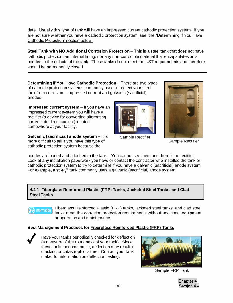
Coated and Cathodically Protected Steel Tank – This is a steel tank that has both an external coating and cathodic protection. An example of a coated and cathodically protected tank brand is the sti-P3® tank. This type of tank is usually installed with galvanic (sacrificial) anodes for cathodic protection. However, these tanks may have an impressed current cathodic protection system if the galvanic (sacrificial) anodes no longer protect the tank from corrosion. If you are not sure whether you have a cathodic pr otection system, see the “Determining If You Have Cathodic Protection” section on the next page.
Cathodically Protected Steel Tank – This is a steel tank without an external coating that has a cathodic protection system. Typically, this type of tank was originally installed as a bare steel tank before May 8, 1985 and had cathodic protection installed at some later date. Usually this type of tank will have an impressed current cathodic protection system. If you are not sure whether you have a cathodic protection system, see the “Determining If You Have Cathodic Protection” section on the next page.
Internally-Lined Steel Tank – This is a steel tank with an internal lining installed. Typically,
this type of tank was installed as a bare steel tank before May 8, 1985 and had an internal lining installed at some later date.
Internally-Lined and Cathodically Protected Steel Tank – This is a steel tank that has both
internal lining and cathodic protection. Typically, this type of tank was installed as a bare steel
tank before May 8, 1985 and had cathodic protection and internal lining installed at some later
date. Usually this type of tank will have an impressed current cathodic protection system. If you
are not sure whether you have a cathodic protection system, see the “Determining If You Have
Cathodic Protection” section below.
Steel Tank with NO Additional Corrosion Protection – This is a steel tank that does not have
cathodic protection, an internal lining, nor any non-corrodible material that encapsulates or is
bonded to the outside of the tank. These tanks do not meet the UST requirements and therefore
should be permanently closed.
Determining If You Have Cathodic Protection – There are two types of cathodic protection systems commonly used to protect your steel tank from corrosion – impressed current and galvanic (sacrificial) anodes.
Impressed current system – If you have an impressed current system you will have a rectifier (a device for converting alternating current into direct current) located somewhere at your facility.
Galvanic (sacrificial) anode system – It is more difficult to tell if you have this type of cathodic protection system because the
Sample Rectifier Sample Rectifier
anodes are buried and attached to the tank. You cannot see them and there is no rectifier. Look at any installation paperwork you have or contact the contractor who installed the tank or cathodic protection system to try to determine if you have a galvanic (sacrificial) anode system.
®
For example, a sti-P3 tank commonly uses a galvanic (sacrificial) anode system.
4.4.1 Fiberglass Reinforced Plastic (FRP) Tanks, Jacketed Steel Tanks, and Clad
Steel Tanks
Fiberglass Reinforced Plastic (FRP) tanks, jacketed steel tanks, and clad steel tanks meet the corrosion protection requirements without additional equipment or operation and maintenance.
Best Management Practices for Fiberglass Reinforced Plastic (FRP) Tanks
Have your tanks periodically checked for deflection (a measure of the roundness of your tank). Since these tanks become brittle, deflection may result in cracking or catastrophic failure. Contact your tank maker for information on deflection testing.
Sample FRP Tank
30

Chapter 4
Section 4.4 31
Best Management Practices for Jacketed Steel Tanks
Have your jacketed steel tanks periodically tested by a qualified contractor to make sure the space between the steel tank and non- corrodible material is tight. This space is known as the interstitial space or secondary containment area. If your primary tank wall were to have a leak and the
Sample Piece of a Jacketed Tank
secondary containment space was not tight, a release could result in costly and time- consuming cleanup.
Best Management Practices for Clad Steel Tanks
If you have clad steel tanks that have cathodic protection then you should have your cathodic protection system tested periodically to make sure that it is operating properly. Section 4.6 describes procedures for operating and maintaining your cathodic protection.
Sample Clad Tank
4.4.2 Coated and Cathodically Protected Steel Tanks
Requirements for Coated and Cathodically Protected Steel Tanks
The coating is on the outside of the tank and must be made of a suitable dielectric material (a material that isolates the tank from the surrounding soil and does not conduct electricity). A sti-P3® tank is the most common type of coated and cathodically protected steel tank.
You must comply with specific testing and record keeping requirements for cathodic
protection. This information can be found in Section 4.6. Before completing the checklist on the next page, read the cathodic protection section and fill out the checklists in that section.
Sample Coated and Cathodically Protected Tank

Chapter 4
Section 4.4 32
Corrosion Protection Checklist
For Coated and Cathodically Protected Steel Tanks
Circle the UST numbers for UST systems
thatare coated and cathodically protected
steel tanks. Fill out the questions below for
these
tanks.
UST # =
1
2
3
4
5
Questions:
N/A
N/A
N/A
N/A
N/A
Circl
e the a
ppropr
iate an
swer
Yes (Y) or No (N)
1. Is your tank coated w ith a suitable le dielectric material?
1
Y
1
N
2
Y
2
N
3
Y
3
N
4
Y
4
N
5
Y
5
N
If no, contact the DEM to determine how you may return to compliance.
2. Do you meet the requirements for your cathodic protection
system? To ans wer “Yes ”her e, you must b e in co m plianc e with
all cathodic protection requirements in Section 4.6. Com plete the
cathodic protection system checklist in Section 4.6.
1
Y
1
N
2
Y
2
N
3
Y
3
N
4
Y
4
N
5
Y
5
N
If no, you must take action to comply with the requirements in Sectio
Ch eck list.”
n 4.6, “Cathodic Protection System
4.4.3 Cathodically Protected Steel Tanks
Requirements and Best Management Practices for Cathodically Protected Steel
Tanks
For any steel tank that uses cathodic protection without a dielectric coating for corrosion protection, installation of that UST system must have begun on or before May 8, 1985. If you have a coated and cathodically protected steel tank, see Section 4.4.2.
An integrity assessment of the tank must have been conducted before adding cathodic protection. The DEM requires that the tank be internally inspected by a trained professional who enters the tank to determine if it is structurally sound and free of corrosion holes.
A code of practice must be followed when adding cathodic protection to your tank, and prior written notification to and approval by the DEM is required.
You must comply with specific testing and record keeping requirements for
cathodic protection. This information can be found in Section 4.6. Before
completing the checklist on the next page, read the cathodic protection section
and fill out the checklists in Section 4.6.

Chapter 4
Section 4.4 33
Keep records of your integrity assessment and cathodic protection installation. These records may be useful in determining whether your tank is in compliance with the corrosion protection requirements.
Corrosion Protection Checklist for Cathodically Protected Steel Tanks
Circle the UST numbers for UST systems that
are cathodically protected steel tanks. Fill out
the questions below for these tanks.
UST # =
1
2
3
4
5
QUESTIONS:
N/A
N/A
N/A
N/A
N/A
Circle the appropriate answer
Yes (Y) or No (N)
1.Did the installation for this U ST system begin on or be fore
May 8, 1985?
1
Y
1
N
2
Y
2
N
3
Y
3
N
4
Y
4
N
5
Y
5
N
If no, then return to compliance: Any tank whe re installation began after May 8, 1985 tha t is
cathodically protected but not coated does not meet the corrosion protection requirements. Contact the
DE M to determine ho w you m ay return to c om plianc e.
2. Did this US T system pass a n integrity assessment?
1
Y
1
N
2
Y
2
N
3
Y
3
N
4
Y
4
N
5
Y
5
N
If no, contact the DEM to determine how you may return to compliance.
3. Do you meet the requirements for your cathodic protection
system? To ans wer “Yes ” her e, you m ust b e in co m plianc e with
all cath odic prote ction r equ irem ents in Se ction 4 .6.
1
Y 1
N 2
Y 2
N 3
Y 3
N 4
Y 4
N 5
Y 5
N
If no, you must take action to comply with the requirements in Section 4.6, “Cathodic Protection System
Ch eck list.”
4.4.4 Internally-Lined Steel Tanks
Requirements and Best Management Practices for Internally-Lined Steel Tanks
For any steel tank that uses internal lining for corrosion protection, installation of that UST system must have begun on or before May 8, 1985.
You must keep all records of repairs for the life of the internally-lined tank.
A code of practice must be followed when adding or repairing an interior lining to your tank and prior written notification to and approval by the DEM is required.

34 Section 4.4
Within 10 years of lining, lined tanks must be internally inspected by a qualified contractor and found to be structurally sound with the lining still performing in accordance with original design specifications. After the initial 10 year inspection, these inspections must be conducted at least every 5 years.
Keep records of your lining installation and lining inspections. These records may be useful in determining whether your tank is in compliance with the corrosion protection requirements. Inspection records are required to be kept for three (3) years beyond the life of a facility.
You should consider adding external corrosion protection (such as cathodic protection) as part of good UST system management.
Sample of a Tank being Interior Lined
Corrosion Protection Checklist for Internally-Lined Steel Tanks
Insert the date of your lining installation for each
tan k bel ow the appropriate U ST # (m m /dd /yy).
W rite N/A (not applicable) for any tanks that are
not internally-lined.
UST # =
1
2
3
4
5
1.Did the installation for this U ST system beg in on or be fore
May 8, 1985? 1
Y 1
N 2
Y 2
N 3
Y 3
N 4
Y 4
N 5
Y 5
N
If no, then return to compliance: Any tank where installation began after May 8, 1985 that is using Internal lining alone does not meet the corrosion protection requirements. These tanks do not meet the regulatory requirements and must be permanently closed.
Chapter 4

Chapter 4
Section 4.4 35
Insert the date of your lining installation for each tank below the appropriate UST # (mm/dd/yy).
Write N/A (not applicable) for any tanks that are not internally-lined.
UST # =
1
2
3
4
5
2. Do you have all records of repairs for your lined tank? If your lined tank has never been repaired, then you will not have any repair records – answer yes to this question.
1 Y
1 N
2 Y
2 N
3 Y
3 N
4 Y
4 N
5 Y
5 N
If no, contact the inspector or repair company that worked on your tank lining. Secure a record of any repairs you have had completed on your lined tank.
3a. Do you have your lined tank periodically inspected? Inspections are required within 10 years of installation and then every 5 years thereafter. If your tank was internally lined less than 10 years ago, this question does not yet apply – skip this question.
3b. What is the date of your most recent lined tank inspection, if applicable?
1 Y
1 N
2 Y
2 N
3 Y
3 N
4 Y
4 N
5 Y
5 N
If the answer to 3a is no, have a lining inspection conducted on your lined tank.
4. Did your lined tank pass its most recent periodic inspection? If your tank was internally lined less than 10 years ago, this question does not yet apply – skip this question.
1 Y
1 N
2 Y
2 N
3 Y
3 N
4 Y
4 N
5 Y
5 N
If no, contact the DEM to determine how you may return to compliance.
4.4.5 Internally-Lined and Cathodically Protected Steel Tanks
Requirements and Best Management Practices for Internally-Lined and Cathodically Protected Steel Tanks
For any steel tank that uses an internal lining and cathodic protection without a dielectric coating (see Section 4.4.2) for corrosion protection, installation of the UST system must have begun on or before May 8, 1985.
When you combine the use of internal lining and cathodic protection, you must meet specific testing and record keeping requirements for cathodic protection, which
are in Section 4.6. Before completing the checklist on the next page, read the cathodic protection section and fill out the checklists in that section.
You must also meet the lining requirements in Section 4.4.4. Before completing the checklist on the next page, read the internally-lined steel tank section and fill out the checklist in that section.
There is one exception which relates to Questions 3 and 4 of the checklist in Section 4.4.4:
• If the integrity of the steel tank was ensured prior to adding cathodic protection, you do not
have to conduct the periodic inspections of the lined tank. The method of integrity assessment is provided in Section 4.4.3 and must determine that the steel tank shell is structurally sound and free of corrosion holes.

Chapter 4
Section 4.4 36
Have your internal lining checked periodically even if the inspections are not required.
Keep records of your lining and cathodic protection installations. These records may be useful in determining whether your tank is in compliance with the corrosion protection requirements.
Corrosion Protection Checklist
for Internally-Lined and Cathodically Protected Steel Tanks
Circle the UST numbers for USTs that are internally-lined and cathodically protected. Fill
out the questions below for these tanks.
UST # =
1 2 3 4 5
QUESTIONS:
N/A N/A N/A N/A N/A
Circle the appropriate answer.
Yes (Y) or No (N)
1. Do you meet the requirements for your cathodic protection system? To answer “Yes” here, you must be in compliance with all cathodic protection requirements in Section 4.6.
1 Y
1 N
2 Y
2 N
3 Y
3 N
4 Y
4 N
5 Y
5 N
If no, you must take action to comply with the requirements in Section 4.6, “Cathodic Protection System Checklist.”
2. Did this UST system pass an integrity assessment at the time cathodic protection was added? Note: Information about the integrity assessment is in Section 4.4.3.
1 Y
1 N
2 Y
2 N
3 Y
3 N
4 Y
4 N
5 Y
5 N
If no, contact the DEM to determine how you may return to compliance.
3. Do you meet the lining requirements in Section 4.4.4? If you answered yes to all applicable questions in Section 4.4.4 for an UST system, then you meet the lining requirements. You can answer “Yes” here for that UST system.
1 Y
1 N
2 Y
2 N
3 Y
3 N
4 Y
4 N
5 Y
5 N
If no, you must take action to meet the requirements described in Section 4.4.4.

Chapter 4
Section 4.4 37
Summary of Compliance with Tank Corrosion Protection
ANSWER THE FOLLOWING QUESTION:
YES
NO
Do all of your underground tanks meet corrosion protection requirements? To answer YES here, you must be able to answer yes to all applicable questions for each type of
tank at your facility.
List tanks that do not meet corrosion protection requirements.
Tank ID Substance
If you answered no, fill out a Return to Compliance Plan and submit it with your Certification of Compliance Form. A Return to Compliance Plan can be found in the accompanying forms booklet.
4.4.6 Steel Tanks With No Additional Corrosion Protection
In general, steel tanks with no additional corrosion protection are not allowed under the DEM UST regulations. However, UST systems storing heating oil of any grade that is consumed on-site solely for heating purposes are exempt from this requirement, if the UST system was installed prior to July 21, 1992.
If you have a regulated UST system without additional corrosion protection, you must notify the DEM immediately and submit a permanent closure application to permanently remove the UST system from service.
Note: A steel tank without corrosion protection in a regulated UST system is out of compliance with the regulations and must be permanently closed.
Summary of Compliance with Tank Corrosion Protection
Make sure you read and complete the checklists in the appropriate tank corrosion protection sections for all of your UST systems before answering the question below.

Chapter 4
Section 4.5 38
Section 4.5 Corrosion Protection for Piping
All of your regulated piping that is in contact with the ground and routinely contains fuel must be protected from corrosion – note that this piping is often underground or buried. This also applies to ancillary equipment such as flexible connectors, swing joints, and other equipment. However, UST systems containing fuel oil that is consumed on-site solely for heating purposes are not required to have corrosion protection if the tank system was installed prior to July 21, 1992.
You can protect this piping and ancillary equipment from corrosion in several ways. It may be:
• made of a non-corrodible material (such as fiberglass or flexible plastic), • made of steel and coated and cathodically protected, or • made of metal and cathodically protected (this option is only allowed for older piping –
installed on or before May 8, 1985).
Metal joints, swing joints, flex connectors, and/or connections associated with piping that are in contact with the ground must be protected from corrosion.
Cathodic protection requires periodic operation and maintenance.
All of your piping and ancillary equipment that is in contact with the ground and routinely contains fuel needs to meet all appropriate construction standards and be installed according to a standard code of practice and the manufacturer’s instructions.
Keep all paperwork related to your corrosion protected piping and ancillary equipment (examples include paperwork related to: installation, cathodic protection, and repair).
To determine requirements and BMPs for corrosion protection of your piping, do the following:
1. Identify the type(s) of piping that are in contact with the ground and routinely contain regulated substances for each UST system. Check the appropriate boxes in the table on the next page.
Note: A piping run may consist of different types of piping. Make sure that you select ALL types of piping associated with each UST.
2. For each type of piping you check, go to the section of this Workbook listed in the right
column of the table. Read the requirements and best management practices and fill out the appropriate checklist(s) in that section. You may need to go to more than one checklist – each piping type has a separate checklist.

Chapter 4
Section 4.5 39
What Type(s) of Piping Do You Have that are in Contact with the Ground and Routinely Contains Regulated Substances?
Go to these sections for information and
UST Number: 1 2 3 4 5
Fiberglass Reinforced Plastic (FRP) Piping Section 4.5.1 Flexible Plastic Piping Section 4.5.1
Coated and Cathodically Protected Steel Piping Section 4.5.2
Cathodically Protected Metal Piping Section 4.5.3
Metal Piping with No Additional Corrosion Protection Section 4.5.4
No Piping in Contact with the Ground No Requirements
Compliance checklists
Note: If your piping type is not listed above, contact the DEM to determine what you must do. If you know the type(s) of piping you have, skip the description information below and proceed to the sections as instructed in the table above. Otherwise, take the following
steps to figure out what is at your facility: • Look under your dispenser and in the sump on top of your tank or at the submersible
pump to see if you can identify the piping. Note that some piping may have metal flexible connectors in these areas. These connectors are only at the ends of the piping and typically do not make up the entire piping run.
• Look through your old records to see if they match any of the names in the descriptions. • Contact the contractor who installed your piping.
Piping Type Descriptions
Fiberglass Reinforced Plastic (FRP) Piping – This piping is made of fiberglass reinforced plastic. It is a rigid piping (it is not flexible). Examples of FRP piping makers include Ameron and Smith Fiberglass Products Inc. This piping type may also have metal connectors associated with it.
Flexible Plastic Piping – This type of piping is made of plastic
Sample FRP Piping
that is flexible. Examples of nonmetal flexible piping brand names include: Poly-Tech, EnviroFlex, GeoFlex, Perma-Flexx, Omniflex, Pisces, and Co-FlexTM. This piping type may also have metal connectors associated with it.
Coated and Cathodically Protected Steel Piping – This is steel piping that has both an external coating and cathodic protection. If you are not sure whether you have a cathodic protection system, see the “Determining If You Have Cathodic Protection” section on Page 40.
Cathodically Protected Metal Piping – This is metal piping without an external coating that has a cathodic protection system. Typically, this type of piping was originally installed as a bare metal before May 8, 1985 and had cathodic protection installed at some later date. If you are not sure whether you have a cathodic protection system, the information in the “determining if you have cathodic protection” section on the next page may help you.
Metal Piping with NO Additional Corrosion Protection – This is metal piping that does not have any additional corrosion protection. This piping is not in compliance with the regulations and needs to be replaced.

Chapter 4
Section 4.5 40
Sample Flexible Piping
Sample Flexible Piping
Sample Flexible Piping
Sample Flexible Piping in a Sump
Closeup of Flexible Piping in a
Sump
Determining If You Have Cathodic Protection – There are two types of cathodic protection systems commonly used to protect your metal piping from corrosion – impressed current (electrical) and galvanic (sacrificial) anodes.
Impressed current system – If you have an impressed current system you will have an electrical rectifier (a device for converting alternating current into direct current) located somewhere at your facility. Sample pictures of rectifiers are provided in Section 4.4.
Galvanic (sacrificial) anode system – It is more difficult to tell if you have this type of cathodic protection system because the anodes are buried and attached to the piping. You cannot see them and there is no rectifier. Look at any installation paperwork you have or contact the contractor who installed the piping or cathodic protection system to try to determine if you have a galvanic (sacrificial) anode system.

Chapter 4
Section 4.5 41
4.5.1 Fiberglass Reinforced Plastic (FRP) Piping and Flexible Plastic Piping
Fiberglass Reinforced Plastic (FRP) Piping and Flexible Plastic Piping types are made of non-corrodible materials and both meet the corrosion protection requirements without additional equipment or operation and maintenance.
Requirements for Fiberglass Reinforced Plastic (FRP) Piping and Flexible Plastic Piping
Any metal piping components associated with these types of piping that are in contact with the ground, such as turbine pump heads, metal flexible connectors, and metal swing joints must be protected from corrosion by one of the following:
• Effectively isolating the metal connector from direct contact with the ground (for
example: by isolating the metal component so it is not in contact with the soil).
• Cathodically protecting metal components in contact with the ground. If you cathodically protect the metal component, you must meet the cathodic protection requirements in Section 4.6. Before completing the checklist on the next page, read the cathodic protection section and fill out the checklists in that section.
Corrosion Protection System Checklist for Fiberglass Reinforced Plastic (FRP) Piping and Flexible Plastic Piping
Circle the UST numbers for UST systems that have FRP or flexible plastic piping. Fill out the questions below for this piping.
UST # =
1 2 3 4 5
QUESTIONS:
N/A N/A N/A N/A N/A
Circle the appropriate answer.
Yes (Y) or No (N)
1. Are all of your metal piping components associated with your fiberglass reinforced plastic (FRP) piping or flexible plastic piping effectively isolated from the soil? If you have no metal piping components, answer “Yes” to this question.
1 Y
1 N
2 Y
2 N
3 Y
3 N
4 Y
4 N
5 Y
5 N
For each UST system for which you answered “No” to this question, proceed to Question 2 and answer that question. For each UST system for which you answered “Yes” to this question, skip Questions 2 and 3; that UST system is in compliance with piping corrosion protection.
2. Are all of your metal components associated with your fiberglass reinforced plastic (FRP) piping or flexible plastic piping that are in contact with the ground and routinely contain regulated substances cathodically protected?
1 Y
1 N
2 Y
2 N
3 Y
3 N
4 Y
4 N
5 Y
5 N
If no, contact the DEM to determine how you may return to compliance.
3. 3. Do you meet the requirements for your cathodic protection system? Fill out the cathodic protection compliance checklist in section 4.6 to make this determination. Answer this question if you have cathodic protection on your metal piping components.
1 Y
1 N
2 Y
2 N
3 Y
3 N
4 Y
4 N
5 Y
5 N
If no, you must take action to comply with the requirements in Section 4.6, “Cathodic Protection System
Checklist.”
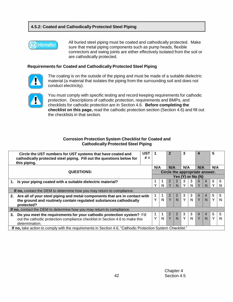
Chapter 4
Section 4.5 42
4.5.2: Coated and Cathodically Protected Steel Piping
All buried steel piping must be coated and cathodically protected. Make sure that metal piping components such as pump heads, flexible connectors and swing joints are either effectively isolated from the soil or are cathodically protected.
Requirements for Coated and Cathodically Protected Steel Piping
The coating is on the outside of the piping and must be made of a suitable dielectric material (a material that isolates the piping from the surrounding soil and does not conduct electricity).
You must comply with specific testing and record keeping requirements for cathodic protection. Descriptions of cathodic protection, requirements and BMPs, and checklists for cathodic protection are in Section 4.6. Before completing the checklist on this page, read the cathodic protection section (Section 4.6) and fill out the checklists in that section.
Corrosion Protection System Checklist for Coated and Cathodically Protected Steel Piping
Circle the UST numbers for UST systems that have coated and cathodically protected steel piping. Fill out the questions below for this piping.
UST # =
1 2 3 4 5
QUESTIONS:
N/A N/A N/A N/A N/A
Circle the appropriate answer.
Yes (Y) or No (N)
1. Is your piping coated with a suitable dielectric material? 1 Y
1 N
2 Y
2 N
3 Y
3 N
4 Y
4 N
5 Y
5 N
If no, contact the DEM to determine how you may return to compliance.
2. Are all of your steel piping and metal components that are in contact with the ground and routinely contain regulated substances cathodically protected?
1 Y
1 N
2 Y
2 N
3 Y
3 N
4 Y
4 N
5 Y
5 N
If no, contact the DEM to determine how you may return to compliance.
3. Do you meet the requirements for your cathodic protection system? Fill out the cathodic protection compliance checklist in Section 4.6 to make this determination.
1 Y
1 N
2 Y
2 N
3 Y
3 N
4 Y
4 N
5 Y
5 N
If no, take action to comply with the requirements in Section 4.6, “Cathodic Protection System Checklist.”

Chapter 4
Section 4.5 43
4.5.3: Cathodically Protected Metal Piping (Other than Steel Piping)
All buried metal piping in contact with soil must be cathodically protected. Make sure that metal piping components such as pump heads, flexible connectors and swing joints are either effectively isolated from the soil or are cathodically protected.
Requirements for Cathodically Protected Metal Piping
For any metal piping in contact with the ground that uses cathodic protection without any coating for corrosion protection, installation of that UST system must have begun on or before May 8, 1985. [If you have a coated and cathodically protected steel piping run, go to Section 4.5.2.]
You must comply with specific testing and record keeping requirements for cathodic protection. Descriptions of cathodic protection, requirements and BMPs, and checklists for cathodic protection are in Section 4.6. Before completing the checklist on the next page, read the cathodic protection section and fill out the checklists in that section.
Keep records of your cathodic protection installation. These records may be useful in determining whether your piping is in compliance with the corrosion protection requirements.
Corrosion Protection System Checklist for Cathodically Protected Metal Piping
Circle the UST numbers for UST systems that have cathodically protected metal piping. Fill out the questions below for this piping.
UST # =
1 2 3 4 5
QUESTIONS:
N/A N/A N/A N/A N/A
Circle the appropriate answer.
Yes (Y) or No (N)
1. Did the installation for this piping begin on or before May 8, 1985? 1 Y
1 N
2 Y
2 N
3 Y
3 N
4 Y
4 N
5 Y
5 N
If no, then to return to compliance: Any metal piping that is in contact with the ground where installation began after May 8, 1985 that is not coated with a suitable dielectric material does not meet the corrosion protection requirements. Submit an Application to the DEM to replace your piping.
2. Are all of your metal piping and metal components that are in contact with the ground and routinely contain regulated substances cathodically protected?
1 Y
1 N
2 Y
2 N
3 Y
3 N
4 Y
4 N
5 Y
5 N
If no, contact the DEM to determine how you may return to compliance.
3. Do you meet the requirements for your cathodic protection system? To answer “Yes” here, you must be in compliance with all cathodic protection requirements in Section 4.6.
1 Y
1 N
2 Y
2 N
3 Y
3 N
4 Y
4 N
5 Y
5 N
If no, you must take action to comply with the requirements in Section 4.6, “Cathodic Protection System Checklist.”

Chapter 4
Section 4.5 44
4.5.4: Metal Piping – No Additional Corrosion Protection
Metal piping with no additional corrosion protection that is in contact with the ground and routinely contains regulated substances is not allowed under DEM
underground storage tank regulations. However, piping for UST systems storing heating oil that is consumed on-site solely for heating purposes is exempted from this requirement if the tank system was installed prior to July 21, 1992.
If you have regulated metal piping without additional corrosion protection that is in contact with the ground, you must notify DEM immediately and submit a proposal to either replace the piping or permanently close the UST system.
Summary of Compliance with Piping Corrosion Protection
Make sure you read and complete the checklists in the appropriate corrosion protection for piping sections for all of your piping that is in contact with the ground and routinely contains
regulated substances before answering the question below.
Summary of Compliance with Piping Corrosion Protection
ANSWER THE FOLLOWING QUESTION:
YES
NO
Does all of your piping that is in contact with the ground and routinely contains regulated substances meet corrosion protection requirements? To answer YES here, you must be able to answer yes to all applicable previous questions for each type of piping at your facility.
List all of your tanks that have piping that does not meet the corrosion protection requirement.
Tank ID Substance
If you answered no, fill out a Return to Compliance Plan and submit it with your Certification of Com
A Return to Compliance Plan can be found in the accompanying Forms Booklet.
Pliance forms.

Chapter 4
Section 4.6 45
Section 4.6: Cathodic Protection If your UST system contains fuel oil that is consumed on-site solely for heating
purposes, you are exempt from cathodic protection operation and maintenance requirements.
Cathodic protection is one option for meeting the corrosion protection requirements of metal UST components that are in contact with the ground and
routinely contain regulated substances and are often buried. Components of your UST system that may have cathodic protection include: metal tanks, piping, and ancillary equipment such as turbine pump heads, flexible connectors, and swing joints.
Impressed Current Systems
An impressed current system uses a rectifier (an electrical device for converting alternating current into direct current) to provide direct current through anodes to the metal tank, piping, or other underground components to achieve corrosion protection. The diagram below illustrates impressed current cathodic protection.
How to tell if you have an impressed current system: You should have an electrical rectifier located somewhere at your facility.
Sample Impressed Current System Diagram
Example Rectifier
Galvanic (or Sacrificial) Anode Systems A galvanic (or sacrificial) anode system uses anodes that are buried and attached to metal UST components for corrosion protection. The anode is more electrically active and will sacrifice itself (corrode) to protect the metal component from corrosion. A sample picture of an anode attached to a tank is shown on the next page.

Chapter 4
Section 4.6 46
How to tell if you have a galvanic anode system: It is more difficult to tell if you have a galvanic anode system because you typically cannot see the anodes and there is no rectifier. The anodes are attached to the underground component they are protecting and are buried. These anodes are usually installed on tanks at the factory (such as on the sti-P3® tank) and can be installed on piping and other underground metal components in the field. Ways to help you determine whether you have a galvanic system are to look at any installation paperwork you might have or to contact the contractor who installed the UST and/or cathodic protection system.
Sample Galvanic (or sacrificial) anode
Requirements and Best Management Practices for Cathodic Protection
Your cathodic protection system must operate continuously to protect the metal components of your UST system that are in direct contact with the ground. • If your cathodic protection system is disconnected or turned off, your
underground UST system components are not protected from corrosion. - Never turn off your rectifier. - Never disconnect a galvanic anode.
• Note that contractors may have to turn off or disconnect your cathodic protection for short periods during repairs.
All cathodic protection systems that are field-installed must be designed by a corrosion expert. Field-installed means that the cathodic protection system was not installed on the tank when the tank or piping was in the factory. An example of a tank that has a factory installed cathodic protection system is the sti-P3® tank.
A corrosion expert must meet specific qualifications. That person must be either: 1. Certified by NACE as a Corrosion Specialist or Cathodic Protection Specialist, or 2. A registered Professional Engineer that has certification or licensing that includes
education and experience in corrosion control of buried or submerged metal piping systems and metal tanks.
A code of practice must be followed when adding a cathodic protection system to your UST system.
You must have your cathodic protection system tested by a qualified cathodic protection tester within 6 months of installation and then at least every 2 years for an impressed system, and every 3 years for a sacrificial anode system. In addition, if you have any repairs conducted to your cathodically protected UST system, or if any maintenance or construction in the area of the structure occurs, you must have a cathodic protection test conducted within 6 months of that repair.

Chapter 4
Section 4.6 47
• You must keep all records of the operation, repair, and testing of the cathodic protection system for 3 years beyond the operational life of the facility. A sample cathodic protection test record is provided for you in Appendix D.
• If your cathodic protection system does not pass the test, have your cathodic protection system evaluated and fixed by a corrosion expert within 30 days and a
report must be submitted to the DEM.
A cathodic protection tester is a person who can demonstrate an understanding of the principles of all common types of cathodic protection systems as applied to buried or submerged metal piping and tank systems.
If you have an impressed current cathodic protection system, you must inspect the rectifier at least every 60 days to make sure that it is on and operating properly. • You must keep all records of these checks for 3 years beyond the operational life
of the facility. A sample impressed current inspection record keeping form is provided for you in Appendix E.
• If your rectifier is not operating within the normal values, contact a corrosion expert to evaluate and fix your cathodic protection system within 30 days.
Keep all paperwork related to your cathodic protection system.
The person who installed your impressed current system should have provided you with paperwork to indicate what the normal operating voltage and amperage values are for your cathodic protection system. If you do not have values for the normal operating voltage and amperage, contact the person who installed the system and obtain that information. Record the amperage and voltage readings and compare them to the normal operating values during each inspection.
Have cathodic protection tests conducted more frequently. The more often you have these tests conducted, the more likely you are to detect cathodic protection problems before releases occur.
Perform inspections of your rectifier more frequently than the 60 day requirement. The more often you inspect the rectifier, the quicker you can detect problems with your cathodic protection system.

Chapter 4
Section 4.6 48
Cathodic Protection System Checklist
Circle the UST numbers that have cathodic
protection and answer the questions below.
UST # =
1
2
3
4
5
Note: If your buried tank and piping components do not have
cathodic protection, then circle N/A (not applicable) for that
UST system. You do not need to answer questions for that
UST.
QUESTIONS:
N/A
N/A
N/A
N/A
N/A
1. What type of cathodic protection system do you have for the
tank of this UST system?
(In the space provided, enter: IC for impressed current, GAL for galvanic, BOTH for both impressed current and galvanic anodes)
2. What type of cathodic protection system do you have for the
piping of this UST system?
(In the space provided, enter: IC for impressed current, GAL for galvanic, BOTH for both impressed current and galvanic anodes)
3. Enter the date or dates of installation for your cathodic
protection system (mm/dd/yy).
4. Does your cathodic protection system operate
continuously?
1
Y
1
N
2
Y
2
N
3
Y
3
N
4
Y
4
N
5
Y
5
N
Answer yes here if you never disconnect your galvanic (sacrificial) anodes and you never turn off your
rectifier or if the only time this occurs is for short periods when a contractor works on your cathodic
protection system.
If no, contact the DEM to determine how to return to compliance.
5. Was your cathodic protection system either designed by a
corrosion expert or installed at the factory?
1
Y
1
N
2
Y
2
N
3
Y
3
N
4
Y
4
N
5
Y
5
N
If no, then to return to compliance:
1. Have a corrosion expert evaluate your existing cathodic protection system. 2. If the design is not adequate, take the necessary steps to have your cathodic protection fixed. 3. Keep a record of the evaluation and repairs. 4. Contact the DEM to determine any further actions necessary to return to compliance.
6. Did you have your cathodic protection system tested within
6 months of installation, at least every 2 years for an
impressed current system, or 3 years for a sacrificial anode
system, and within 6 months following any repairs to your
cathodically protected UST system, or within 6 months of any
maintenance or construction in the area of the UST system?
1
Y
1
N
2
Y
2
N
3
Y
3
N
4
Y
4
N
5
Y
5
N
If no, have a cathodic protection test conducted by a qualified cathodic protection tester as soon as possible. Contact the DEM to determine any further actions necessary to return to compliance.

Chapter 4
Section 4.6 49
Circle the UST numbers that have cathodic
protection and answer the questions below.
UST # =
1
2
3
4
5
Note: If your buried tank and piping components do not have
cathodic protection, then circle N/A (not applicable) for that
UST system. You do not need to answer questions for that
UST.
QUESTIONS
N/A
N/A
N/A
N/A
N/A
7. Do you have records of your cathodic protection tests? Answer yes here if one of the following apply:
1
Y
1
N
2
Y
2
N
3
Y
3
N
4
Y
4
N
5
Y
5
N
1. You have records of all cathodic protection tests as described in this section.
2. You have no records and your cathodic protection system was installed less than 6 months ago.
Enter the date of your most recent test (mm/dd/yy).
If no, contact the person who performed your cathodic protection tests and obtain records of your cathodic protection testing.
8. Did your most recent cathodic protection test pass?
1
Y
1
N
2
Y
2
N
3
Y
3
N
4
Y
4
N
5
Y
5
N
If no, have a corrosion expert evaluate your cathodic protection system and fix any problems as soon as possible. Also have a cathodic protection test conducted within 6 months of the repair and make sure the cathodic protection system passes the test.
Questions 9 – 11 are for cathodic protection systems with rectifiers only (Impressed Current
Systems). Skip these questions if you only have galvanic (sacrificial) anodes.
9. Do you inspect your rectifier at least every 60 days?
1
Y
1
N
2
Y
2
N
3
Y
3
N
4
Y
4
N
5
Y
5
N
If no, begin inspecting your rectifier at least every 60 days by recording amperage and voltage readings on your rectifier and comparing those readings with the normal operating values.
10. Do you have records of your rectifier inspections? Answer yes here if one of the following apply:
1
Y
1
N
2
Y
2
N
3
Y
3
N
4
Y
4
N
5
Y
5
N
1. You have records of all the rectifier inspections that are required as described in this section.
2. You have at least 2 records and your cathodic protection system was installed less than 6 months ago.
3. You have at least 1 record and your cathodic protection system was installed less than 4 months ago.
4. You have no records yet and your cathodic protection system was installed less than 2 months ago.
Enter the date of your most recent inspection (mm/dd/yy).
If no, begin keeping records of your rectifier inspection.
11. Did your most recent cathodic protection inspection results
fall within the amperage and voltage ranges established by the
corrosion expert? If you do not have voltage and amperage
ranges established by the corrosion expert, call the person who installed your cathodic protection system and get those values
1
Y
1
N
2
Y
2
N
3
Y
3
N
4
Y
4
N
5
Y
5
N
If no, have a corrosion expert evaluate your cathodic protection system and fix any problems as soon
as possible. Also have a cathodic protection test conducted within 6 months of the repair.

Chapter 4
Section 4.7 50
50
Section 4.7: Leak Detection for Tanks
If your UST system contains fuel oil that is consumed on-site solely for
heating purposes, you are not required to have leak detection.
Leak detection (also called release detection) requirements for single-walled
tanks include Automatic Tank Gauging (ATG), Tightness Testing, and
Inventory Control. For tanks with secondary containment, or double-walled
tanks, leak detection requirements include Continuous Interstitial
Monitoring and interstitial tightness testing.
If you have a Waste oil or motor oil tank, then you must comply with one of the
following leak detection requirements:
If the waste oil or motor oil tank is single-walled and less than or equal to
2,000 gallons, you must conduct either:
1. Automatic tank gauging (0.2 gph monthly leak test required) and tank
tightness testing at 5-year intervals, or if the tank has been installed for
more than 20 years, tank tightness testing every 2 years, or annual
tightness testing if the tank has been installed for a period of thirty (30)
years); or
2. Annual tank tightness testing and inventory control modified for a
waste oil or motor oil tank (See Section 4.7.5).
If the waste oil or motor oil tank is single-walled and greater than 2,000
gallons, you must conduct:
1. Automatic tank gauging (0.2 gph monthly leak test required) and tank
tightness testing at 5-year intervals, or if the tank has been installed for
more than 20 years, tank tightness testing every 2 years, or annual
tightness testing if the tank has been installed for a period of thirty (30)
years).
If the waste oil or motor oil tank is double-walled, you must have:
1. Continuous Interstitial Monitoring.
2. An interstitial tightness test when the UST has been installed for 30 years, and every 2 years thereafter.
If you have a Diesel Generator UST, then you must comply with all of
the leak detection requirements for a diesel tank, except for inventory
control. Diesel generator USTs are not required to conduct inventory
control. The requirements for single-walled and double-walled diesel
generator UST are different:
If the diesel generator tank is single-walled, you must:

Chapter 4
Section 4.7 51
51
1. Install and operate an approved automatic tank gauging system
2. Perform a tightness test once every 2 years
If the diesel generator tank is double-walled, you must perform:
1. Continuous interstitial monitoring
2. An interstitial tightness test when the UST is 30 years old and every
2 years thereafter
General Requirements and Best Management Practices for ALL Tank Leak Detection
Methods
You are required to test and conduct system checks on your leak detection equipment. The following tests are required to be conducted annually:
• Automatic Tank Gauge System Test
• Continuous Interstitial Monitoring System Test • Tank Tightness Testing for single-walled USTs (double-walled tanks installed for
a period of 20 years must perform an interstitial tightness test every 2 years)
The following tests/checks are required to be conducted monthly:
• Automatic Tank Gauge System Check to ensure it is operating effectively • Automatic Tank Gauge System Leak Test (for single-walled USTs)
• Reconcile your Inventory You are required to record your inventory daily (not required for double-walled UST).
Your release detection must be installed, calibrated, operated, and maintained
according to the manufacturer’s instructions.
The following information/documentation must be kept for 3 years beyond the life of
the facility: • annual leak detection device test results
• tank/piping tightness test results • all repair documentation
The following must be kept for 3 years:
• maintenance/inventory records • strip chart and manual recordings for continuous monitoring
• results of all monthly system checks • shear valve annual checks
If you ever suspect or confirm a release, you must take appropriate action and, if
necessary, report the release. Refer to Section 4.9 for information on what to do.
Never ignore leak detection alarms or failed leak detection tests. Treat them
as suspected leaks!
If you have hazardous substance tanks (as defined under CERCLA), you must have
double-walled tanks and use interstitial monitoring for release detection unless you
have obtained a waiver from the DEM.
All leak monitoring devices shall not be shut off or deactivated at any time except for
repair; any deactivation must be reported to the DEM. All monitoring devices shall

Chapter 4
Section 4.7 52
52
To determine requirements and BMPs for release detection of your tank(s), do the following:
1. Identify the type(s) of release detection you use for your tanks. Check the
appropriate boxes in the table below.
Different tanks at your facility may use different types of leak
detection. Make sure to select the appropriate type of leak detection
for each tank at your facility.
You may have more than one type of leak detection for a tank at your
facility. For the purposes of determining your compliance, you should
check only the method(s) of leak detection you are using to comply with
the release detection for tanks portion of the UST regulations. If you use
multiple types of leak detection for a single tank, then you need to meet
the requirements for each type of release detection you checked.
2. For each type of leak detection you checked, go to the appropriate section and read
and fill out the appropriate checklist(s). You may need to go to more than one checklist
– each leak detection type has a separate checklist.
employ an audible alarm and a visual indicator, which shall be located as to be heard
and seen by the owner/operator or other personnel during normal working hours.
Keep all schedules of required calibration and maintenance provided by the
equipment manufacturer.
Periodically have a qualified UST contractor, such as the vendor who installed your
release detection system, service all the system components according to the
manufacturer’s service instructions. • Components can wear out and must be checked periodically. Many vendors
recommend or require this maintenance activity at least once annually.
Make sure your vendor or installer provides you with the information and training
necessary to make sure your release detection equipment works effectively to
detect leaks. If you don’t know how your system works, you will fail inspections and
may find yourself with violations and penalties. Worse, you may discover that you
have had a leak and may have to pay for extensive cleanup of a contaminated site
and for damages caused to others. It is your responsibility to know how to operate
all your release detection devices properly so that you meet regulatory
requirements and protect the environment.
Make sure employees who run, monitor, or maintain the release detection
system are aware of correct operating procedures. Develop and maintain
regular training programs for all employees.

Chapter 4
Section 4.7 53
53
What Type(s) Leak Detection Do You Use for Your Tank(s)? Go to these sections for
UST Number: 1 2 3 4 5
compliance checklists
Automatic Tank Gauging (ATG) Section 4.7.1
Interstitial Monitoring for Double-Walled Tanks Section 4.7.2
Tank Tightness testing Section 4.7.3
Inventory Control
Inventory Control for a Waste Oil Tank Section 4.7.4
Section 4.7.5
Check here if your tank contains a hazardous substance. Section 4.7.2
If you have an UST system that contains a hazardous substance (one common example is
antifreeze), check the last row of the table below for that UST.
Information and
If your tank leak detection is not listed above, contact the DEM to determine what you must do.
If you know the type(s) of leak detection you have, skip the description information
below and proceed as instructed in the table above. Otherwise, take the following
steps to figure out what is at your facility:
• Read the descriptions below of the different tank leak detection types. Look through your old
records to see if they match any of the names in the descriptions.
• Contact the contractor who installed your leak detection system.
Leak Detection Descriptions
Automatic Tank Gauging (ATG) – An ATG system consists of a probe permanently installed in a
tank and wired to a monitor to provide information such as fuel level and temperature. You
should have an ATG monitor mounted somewhere at your facility. ATG systems automatically
calculate the changes in fuel volume that can indicate a leaking tank and can be set to alarm
when there is a suspected problem with your tank.
Sample ATG Monitor Sample ATG Monitor

Chapter 4
Section 4.7 54
54
Double-Walled Tanks with Interstitial Monitoring – Secondary containment is an additional
barrier between the portion of an UST system that contains fuel and the outside environment.
Secondary containment is provided by the outer tank wall of a double-walled system.
Hazardous substance tanks must be double-walled with interstitial monitoring or you
must obtain a waiver from the DEM. The area between the inner and outer barriers is called
the interstitial space (or annular space). You must have interstitial monitoring ports on the
pavement at your facility. Electronic probes in the interstitial space are connected to and
monitored by electronic equipment (such as an automatic tank gauge).
Inventory Control – This method involves measuring the contents of the tank and recording the
amount of fuel pumped each day and reconciling that data with measurements and records of
fuel delivery. Typically, a measuring stick or an ATG is used to take the measurements.
Sample Part of a Measuring Stick
Tank Tightness Testing – This is a tank testing method that is capable of determining whether or not an underground storage tank, line, or system is leaking, as defined by NFPA 329, “Handling Releases of Flammable and Combustible Liquids and Gases.” The test is capable of accurately detecting a tank or a tank and line leak of 0.1 gallons per hour, adjusted for all variables, with a probability of detection of no less than 95 percent and a probability of false detection of no more than 5 percent. The test method must be approved by the DEM prior to use, follow the manufacturer’s protocol, and be conducted by persons who are licensed by the DEM.

Chapter 4
Section 4.7 55
55
4.7.1: Automatic Tank Gauging (ATG)
ATG systems automatically calculate the
changes in fuel volume that can indicate a
leaking tank. ATG is not required for tanks
upgraded by lining or cathodic protection
for the first 10 years after the upgrade.
Sample ATG
Requirements and Best Management Practices for Automatic Tank Gauging (ATG)
Systems
LEAK DETECTION TEST
You are required to use your ATG system to test for leaks at least once every Month (for single-walled USTs).
• Remember to test each tank.
• Make sure you are properly testing the portion of the tank that routinely contains
regulated substances.
• Make sure that the amount of fuel in your tank is sufficient to run the ATG leak
test. The tank must contain a minimum amount of fuel to perform a valid leak
detection test.
• One source for determining that minimum amount is the performance
certification for your leak detection equipment.
SYSTEM CHECK
Your ATG system is required to be tested on a monthly basis to ensure that they are
operating according to the manufacturer’s specifications.
• Read your owner’s manual, run the appropriate tests, and see if your ATG
system is set up and working properly.
• Most ATG systems have a “test” or “self-diagnosis” mode that may run these
checks.
All ATG systems must be inspected, calibrated, and tested annually by a qualified
contractor to insure proper operation.

Circle the UST numbers for tanks that use ATGs.
UST # =
1
2
3
4
5
QUESTIONS:
N/A
N/A
N/A
N/A
N/A
Circle the appropriate answer
Cicle the appropriate answer
Yes (Y) or No (N)
1. Do you use your ATG to check each tank for leaks/releases
at least once every month? Don’t forget that you also need to
have sufficient fuel in each tank for a valid test.
1
Y
1
N
2
Y
2
N
3
Y
3
N
4
Y
4
N
5
Y
5
N
If no, begin using your ATG to check each tank for releases at least once every month.
2. Do you have records of your last 36 months of leak
detection tests? Appendix F contains a sample record keeping
form.
1
Y
1
N
2
Y
2
N
3
Y
3
N
4
Y
4
N
5
Y
5
N
If no, you may be able to obtain historical records of leak tests from your ATG. Consult your owner’s
manual to determine how to do this. Otherwise, begin keeping records of release detection testing.
3. Do you have records of your last 36 months of ATG system
checks to make sure it was working properly?
1
Y
1
N
2
Y
2
N
3
Y
3
N
4
Y
4
N
5
Y
5
N
If no, begin performing monthly system checks of your ATG system.
4. Do you have records of the required annual calibration,
inspection and test by a UST contractor for the last 3 years?
Enter the date of the most recent test. mm/dd/yy
1
Y
1
N
2
Y
2
N
3
Y
3
N
4
Y
4
N
5
Y
5
N
If no, contact the person who did the work and obtain these records.
All records pertaining to the equipment manufacturer, warranties, maintenance
requirements, repairs, and testing shall be maintained on-site for the life of the
system or at an alternative location approved by the Director of the DEM in writing.
Test your tanks more frequently in order to catch leaks sooner and reduce cleanup
costs and problems.
Periodically have a qualified UST contractor, such as the vendor who installed your
ATG, service all the ATG system components according to the manufacturer’s
service instructions. Many vendors recommend or require this maintenance activity
at least once annually.
Checklist for Automatic Tank Gauging
Chapter 4
56 Section 4.7

Chapter 4
Section 4.7 57
4.7.2: Interstitial Monitoring for Double-Walled Tanks
Double-walled tanks have an additional barrier between the portion of an UST
system that contains regulated substances and the outside environment.
Secondary containment is provided by the outer tank wall of a double-
walled system. The area between the inner and outer walls is called the
interstitial space or annular space and can be monitored to catch problems
before regulated substances reach the environment. Hazardous substance
tanks must be double-walled with interstitial monitoring or you must
obtain waiver from the DEM.
Interstitial monitoring systems must be designed, constructed, and installed to
detect a leak from any part of the tank that routinely contains fuel. For
double-walled tanks, the test method must be able to detect a release
through the inner wall of the double-walled tank.
Requirements and Best Management Practices for Double-Walled Tanks with Interstitial
Monitoring
All leak monitoring devices shall not be shut off or deactivated at any time except for
repair and must be reported to the DEM. All monitoring devices shall employ an
audible alarm and a visual indicator, which shall be located as to be heard and seen
by the owner/operator or other personnel during normal working hours.
SYSTEM CHECK
Test your interstitial monitoring system monthly to ensure it is operating effectively.
• Read your owner’s manual, run the appropriate tests, and see if your interstitial
monitoring system is set up and working properly.
• Most interstitial monitoring systems have a “test” or “self diagnosis” mode that
may run these checks.
Have a qualified UST contractor inspect, calibrate, and test your interstitial monitoring
system annually.
You should frequently test your interstitial monitoring system to make sure it is
working properly.
Periodically have a qualified UST contractor, such as the vendor who installed your
electronic interstitial monitoring system, service all the system components
according to the manufacturer’s service instructions.
Testing more often than monthly can catch leaks sooner and reduce cleanup costs
and problems.

Chapter 4
Section 4.7 58
Circle the UST numbers for tanks that use
interstitial monitoring.
UST # =
1
2
3
4
5
QUESTIONS:
N/A
N/A
N/A
N/A
N/A
Circle the appropriate answer
le the appropriate answer
Yes (Y) or No (N)
1. Do you continuously use interstitial monitoring to check
each tank for leaks/releases.
1
Y
1
N
2
Y
2
N
3
Y
3
N
4
Y
4
N
5
Y
5
N
If no, contact the DEM to determine how to return to compliance.
2. Do you have records of monthly interstitial monitoring
system checks for the past 36 months?
Appendix F contains a sample record keeping form.
1
Y
1
N
2
Y
2
N
3
Y
3
N
4
Y
4
N
5
Y
5
N
If no, begin conducting monthly checks of your interstitial monitoring system and maintain records of
these checks.
3. Do you have all records of maintenance and repair of your
interstitial monitoring system conducted in the last 3 years?
1
Y
1
N
2
Y
2
N
3
Y
3
N
4
Y
4
N
5
Y
5
N
If no, contact the person who did the work and obtain the records.
4. Do you have records of the required annual inspection,
calibration, and test by a UST contractor for the last 3 years?
Enter the date of the most recent test. MM/DD/YY
1
Y
1
N
2
Y
2
N
3
Y
3
N
4
Y
4
N
5
Y
5
N
If no, contact the person who did the testing and obtain the records.
Checklist for Interstitial Monitoring of Double-Walled Tanks

Chapter 4
Section 4.7 59
4.7.3: Tightness Testing for Single-Walled Tanks
Requirements and Best Management Practices for Tank Tightness Testing
You must perform tank tightness tests on all single-walled tanks.
All failed tests must be immediately reported to the DEM. Tightness tests for single-walled USTs must be performed annually. Tightness tests must be conducted by a trained tester licensed by the DEM.
• Make sure that the method of tank tightness testing is approved by the DEM. • Keep the results of all tightness tests for 3 years beyond the life of the facility.
Checklist for Tank Tightness Testing
Circle the UST numbers for tanks that use tank
tightness testing.
UST # =
1
2
3
4
5
QUESTIONS:
N/A
N/A
N/A
N/A
N/A
Circle the appropriate answer
le the a
ppropriate answer
Yes (Y) or No (N)
If you have a single-walled UST:
Do you have results of a tank tightness test conducted
within the past year?
Enter the date of your most recent test: mm/dd/yy
1
Y
1
N
2
Y
2
N
3
Y
3
N
4
Y
4
N
5
Y
5
N
If no, have a tightness test conducted and keep the record. If you had a tightness test conducted but do not
have the record, contact the tightness testing vendor to obtain a record.

Chapter 4
Section 4.7 60
4.7.4: Tank Tightness Testing for Double-Walled Tanks
Requirements and Best Management Practices for Tank Tightness Testing
You must perform tightness test on the interstitial space between the tank’s walls when the tank has been installed for a period of twenty years, and once every two years thereafter.
Interstitial space tightness testing is applicable for testing the dry annular space only.
The test results must be submitted to the Department within 30 calendar days of test completion for passing tests and 7 calendar days for failed tests.
All failed tests must be immediately reported to the DEM and promptly investigated in accordance with the RI DEM UST regulations.
Tightness tests must be conducted by a trained tester licensed by the DEM.
• Make sure that the method of tank tightness testing is approved by the DEM. • Keep the results of all tightness tests for 3 years beyond the life of the facility.

Chapter 4
Section 4.7 61
4.7.4.1: Exemption for Double-walled Brine Interstitial Tanks
Double-walled USTs with a brine solution or other inert liquid in the interstitial space are not required to have an interstitial space tightness test performed and instead must continuously monitor for a change in fluid level in the reservoir and interstice.
Checklist for Tank Interstitial Space Tightness Testing
Circle the UST numbers for double-walled tanks
with a dry interstitial space.
Tightness testing.
UST # =
1
2
3
4
5
QUESTIONS:
N/A
N/A
N/A
N/A
N/A
Circ
le the a
ppropriate answer
Yes (Y) or No (N)
Tank does not have a brine solution or other inert liquid in
the interstitial space and the tank was installed 20 years
ago or more.
Do you have passing results of a test for tightness on the
interstitial space of the tank’s walls performed when the tank has
been installed for 20 years and every 2 years thereafter?
Enter the date of your most recent test: mm/dd/yy
1
Y
1
N
2
Y
2
N
3
Y
3
N
4
Y
4
N
5
Y
5
N
If no, have a tightness test conducted and keep the record. If you had a tightness test conducted,
but do not have the record, contact the tightness testing vendor to obtain a record.
Enter the date of your most recent test: mm/dd/yy Enter the name of company that conducted the test
1
Y
1
N
2
Y
2
N
3
Y
3
N
4
Y
4
N
5
Y
5
N
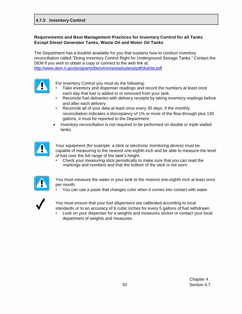
Chapter 4
Section 4.7 62
4.7.5 Inventory Control
Requirements and Best Management Practices for Inventory Control for all Tanks
Except Diesel Generator Tanks, Waste Oil and Motor Oil Tanks
The Department has a booklet available for you that explains how to conduct inventory
reconciliation called “Doing Inventory Control Right for Underground Storage Tanks.” Contact the
DEM if you wish to obtain a copy or connect to the web link at:
http://www.dem.ri.gov/programs/benviron/assist/usterp/pdf/doitrite.pdf
For Inventory Control you must do the following: • Take inventory and dispenser readings and record the numbers at least once
each day that fuel is added to or removed from your tank. • Reconcile fuel deliveries with delivery receipts by taking inventory readings before
and after each delivery. • Reconcile all of your data at least once every 30 days. If the monthly
reconciliation indicates a discrepancy of 1% or more of the flow-through plus 130
gallons, it must be reported to the Department.
• Inventory reconciliation is not required to be performed on double or triple walled
tanks.
Your equipment (for example: a stick or electronic monitoring device) must be
capable of measuring to the nearest one-eighth inch and be able to measure the level
of fuel over the full range of the tank’s height. • Check your measuring stick periodically to make sure that you can read the
markings and numbers and that the bottom of the stick is not worn.
You must measure the water in your tank to the nearest one-eighth inch at least once
per month.
• You can use a paste that changes color when it comes into contact with water.
You must ensure that your fuel dispensers are calibrated according to local
standards or to an accuracy of 6 cubic inches for every 5 gallons of fuel withdrawn. • Look on your dispenser for a weights and measures sticker or contact your local
department of weights and measures.

Chapter 4
Section 4.7 63
Checklist for Inventory Control
Circle the UST numbers for tanks that use
inventory control.
UST # =
1
2
3
4
5
QUESTIONS:
N/A
N/A
N/A
N/A
N/A
Circle the appropriate answer
Yes (Y) or No (N)
1. Do you perform inventory control properly? Appendix G
contains sample inventory worksheets. A sample manual tank
gauging record can be found in Appendix H.
1
Y
1
N
2
Y
2
N
3
Y
3
N
4
Y
4
N
5
Y
5
N
This includes: 1. Taking inventory and dispenser readings at least once each day that fuel is added
to or removed from your tank.
2. Reconciling fuel deliveries with delivery receipts by taking inventory readings before
and after each delivery.
3. Reconciling all of your data at least once every 30 days.
4. Calculation of 1% flow- through plus 130 gallons.
If no, begin performing proper inventory control.
2. Do you have records for, at minimum, the last 36 months
of inventory control (including water measurements)? A
sample inventory control worksheet is provided in Appendix G.
1
Y
1
N
2
Y
2
N
3
Y
3
N
4
Y
4
N
5
Y
5
N
If no, begin keeping records of inventory control and water measurements.
3. Is the measuring equipment used capable of measuring
to the nearest one-eighth inch over the entire height of the
tank?
1
Y
1
N
2
Y
2
N
3
Y
3
N
4
Y
4
N
5
Y
5
N
If no, get equipment (for example, a stick) that meets these requirements.
4. Do you measure the water in each of your tanks at least
once every 30 days to the nearest one-eighth inch?
1
Y
1
N
2
Y
2
N
3
Y
3
N
4
Y
4
N
5
Y
5
N
If no, begin taking water readings of each tank at least once every 30 days.
ys.

Chapter 4
Section 4.7 64
4.7.6 Inventory Control for Single-Walled Waste Oil and Motor Oil Tanks Less Than 2,000 Gallons
Requirements and Best Management Practices for Inventory Control for single-walled
waste oil and motor oil Tanks 2,000 gallons or less
The Department has a booklet available for you to keep that explains how to conduct inventory
reconciliation for waste oil and motor oil tanks. Contact the DEM if you wish to obtain a copy.
For Inventory Control for single-walled waste oil and motor oil tanks 2,000
gallons or less, you must do the following:
• Once each week, take the tank out of service for 36 hours and perform liquid level
measurements before and after this period. The difference in volume must be 10
gallons or less for tanks up to 550 gallons, 13 gallons or less for tanks between
551 and 1,000 gallons, and 26 gallons or less for tanks between 1,001 and 2,000
gallons. • Once a month, average the four weekly changes in tank volume (taking into
consideration positive and negative numbers). This average is required to be 5
gallons or less for tanks up to 550 gallons, 7 gallons or less for tanks between
551 and 1,000 gallons, and 13 gallons or less for tanks between 1,001 and 2,000
gallons. • If any weekly or monthly change exceeds the allowable amount, then a leak is
suspected and the Department must be contacted immediately.
Your stick must be capable of measuring to the nearest one-eighth inch and be able
to measure the level of fuel over the full range of the tank’s height. • Check your measuring stick periodically to make sure that you can read the
markings and numbers and that the bottom of the stick is not worn.
You must measure the water in your tank to the nearest one-eighth inch at least once
per month.
• You can use a paste that changes color when it comes into contact with water.

Chapter 4
Section 4.7 65
Checklist for Inventory Control for Single-Walled Waste Oil and Motor Oil Tanks that are
2,000 gallons or less
Circle the UST number of the waste oil or
motor oil tank using inventory
control.
UST # =
1
2
3
4
5
QUESTIONS:
N/A
N/A
N/A
N/A
N/A
Circle the appropriate answer
Yes (Y) or No (N)
1. Do you perform inventory control properly? Appendix G
contains a sample inventory control worksheet. A sample manual
tank gauging record can be found in Appendix H.
1
Y
1
N
2
Y
2
N
3
Y
3
N
4
Y
4
N
5
Y
5
N
This includes: 1. Once a week take tank out of service for 36 hours.
2. Take liquid measurements before and after the 36 hour shut down.
3. Reconciling your 4 weeks of data once every 30 days.
If no, begin performing proper inventory control.
2. Do you have records for, at minimum, the last 36 months
of inventory control (including water measurements)? A
sample inventory control worksheet is provided in Appendix G.
1
Y
1
N
2
Y
2
N
3
Y
3
N
4
Y
4
N
5
Y
5
N
If no, begin keeping records of inventory control and water measurements.
3. Is the measuring equipment capable of measuring to the
nearest one-eighth inch over the entire height of the tank?
1
Y
1
N
2
Y
2
N
3
Y
3
N
4
Y
4
N
5
Y
5
N
If no, get equipment (for example, a stick) that meets these requirements.
4. Do you measure the water in each of your tanks at least
once every 30 days to the nearest one-eighth inch?
1
Y
1
N
2
Y
2
N
3
Y
3
N
4
Y
4
N
5
Y
5
N
If no, begin taking water readings of each tank at least once every 30 days.
ys.

Chapter 4
Section 4.7 66
Summary of Compliance with Release Detection for Tanks
Make sure you read and complete the checklists in the appropriate release detection sections
for all of your tanks before answering the questions below.
Summary of Compliance with Release Detection for Tanks
ANSWER THE FOLLOWING QUESTION: YES NO
1.Are all of your tanks in compliance with release detection requirements?
To answer YES here, you must be able to answer yes to all applicable questions for
each type of tank release detection at your facility. If you have a hazardous
substance tank please read the information below this question.
List all tanks that do not meet Release Detection requirements.
Tank ID Substance
If you answered no, fill out a Return to Compliance plan and submit it with your certification
of compliance. A Return to Compliance plan can be found in the accompanying forms
booklet.
If you have tanks that contain a hazardous substance listed on the CERCLA list of
hazardous substances (an example would be a tank that contains antifreeze), you must
meet one of the following for each of these tanks:
1. You must have a double-walled tank with interstitial monitoring (see Section 4.7.2)
or
2. You must have a waiver from the DEM.

Chapter 4
Section 4.8 67
What Type(s) of Piping Do You Have at Your Facility? Go to these sections for
UST Number: 1 2 3 4 5
compliance checklists Pressurized (with some piping underground) Section 4.8.1 Suction (with some piping underground) Section 4.8.2
Gravity (with some piping underground) No Requirements
No Underground Piping No Requirements
No Piping No Requirements
Section 4.8: Leak Detection for Piping If your UST system contains fuel oil that is consumed on-site solely for heating purposes you are not required to have leak protection for your piping.
There are pressurized, suction, and gravity piping delivery systems for piping that could be used with USTs. In addition, piping could either be above or
below ground and either single or double walled. There are line leak detection requirements for underground pressurized and suction piping. The leak detection requirements are different depending on the type of piping delivery system. Do not include fill pipes as part of your piping.
To determine requirements and BMPs for leak detection of your piping, do the following:
1. Identify the type(s) of piping you have at your facility. Check the appropriate boxes in the table below.
Different piping runs at your facility may use different types of fuel delivery systems. Make sure to select the appropriate type of fuel delivery system for each piping run at your facility.
Note: If all piping associated with an UST system is aboveground, then that piping has no requirements for leak detection.
2. For each type of piping you check in the table below, go to the appropriate section and
read and fill out the appropriate checklist(s) for piping release detection. You may need to go to more than one checklist.
Information and
If you do not know the type(s) of piping you have, take the following steps to figure out
what is at your facility: • Read the descriptions below of the different types of fuel delivery systems for piping. • Look through your old records to see if they match any of the names in the descriptions. • Contact the contractor who installed your piping system. • Contact your service contractor/environmental consultant for assistance.

Chapter 4
Section 4.8 68
Fuel Delivery System Descriptions
Pressurized fuel delivery pushes fuel from the tank to the dispenser through piping by using a submersible turbine pump (STP) located inside the tank. Usually there is a STP head in a sump above the tank. These sumps are often covered with a lid and may also have a sump cover under the lid.
Sample STP Head in a Sump on Top of a Tank
Sample STP Head in a Sump on Top of a Tank
Sample Lid and Sump Cover
Suction fuel delivery pulls fuel from the tank to the dispenser through the piping by using a suction pump located at the dispenser. You should be able to tell if you have suction piping by looking for a suction pump (you may see pulleys and belts) inside the dispenser. Also, there will not be a pump in a sump above the tank.
Gravity feed fuel delivery has no pump and relies on the downward slope of the piping to transport fuel from the tank to the dispenser.
Example of a Suction Pump
Inside a Dispenser

Chapter 4
Section 4.8 69
4.8.1 Pressurized Piping
Each pressurized piping run must have an automatic Line Leak Detector (LLD)
installed. You must meet specific requirements for your LLDs. See Section 4.8.1.1.
Along with a LLD, each pressurized piping must have one of the following:
• interstitial monitoring – to use this method, your piping must be double-walled
and you must be monitoring the interstitial space continuously for releases.
• annual line tightness test – If you have single-walled piping, you must have a
line tightness test conducted at least annually. See Section 4.8.3 for information and checklists for line tightness testing.
Contact the DEM if you do not use one of these methods.
If you have interstitial monitoring (Section 4.7.2), the requirements are the same for both tanks and piping. In addition, you must ensure the following for interstitial monitoring for piping:
• Sensors are typically located in the piping collection sump areas for interstitial monitoring. These sumps must be tight and free of leaks for piping interstitial monitoring to operate correctly.
• Piping should slope to the sump containing the monitoring probe.
• Check to see that sensors are located near the bottom of the sump so that they activate quickly when a release occurs.
• Sensors must be at least 1 inch below the lowest penetration fitting in the sump .
A test for tightness on the interstitial space of double-walled piping shall be performed when the piping system has been installed for a period of twenty years, and once every 2 years thereafter.
. Pressurized piping must be equipped with an emergency shut-off valve designed to close automatically in the event of impact or fire exposure. The automatic closing feature of the valve must be checked yearly by manually tripping the hold-open linkage. Records must be kept of this inspection check.
. Single-walled piping systems must be permanently closed by December 22, 2017 or within 32 years of the date of installation, whichever is later.
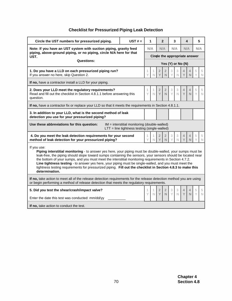
Chapter 4
Section 4.8 70
Circle the UST numbers for pressurized piping.
UST # =
1
2
3
4
5
Note: If you have an UST system with suction piping, gravity feed
piping, above-ground piping, or no piping, circle N/A here for that
UST.
Questions:
N/A
N/A
N/A
N/A
N/A
Circle the appropriate answer
le the a
ppropri
ate ans
wer
Yes (Y) or No (N)
1. Do you have a LLD on each pressurized piping run? If you answer no here, skip Question 2.
1
Y
1
N
2
Y
2
N
3
Y
3
N
4
Y
4
N
5
Y
5
N
If no, have a contractor install a LLD for your piping.
2. Does your LLD meet the regulatory requirements? Read and fill out the checklist in Section 4.8.1.1 before answering this question.
1
Y
1
N
2
Y
2
N
3
Y
3
N
4
Y
4
N
5
Y
5
N
If no, have a contractor fix or replace your LLD so that it meets the requirements in Section 4.8.1.1.
3. In addition to your LLD, what is the second method of leak
detection you use for your pressurized piping?
Use these abbreviations for this question: IM = interstitial monitoring (double-walled) LTT = line tightness testing (single-walled)
4. Do you meet the leak detection requirements for your second
method of leak detection for your pressurized piping?
1
Y
1
N
2
Y
2
N
3
Y
3
N
4
Y
4
N
5
Y
5
N
If you use:
Piping interstitial monitoring - to answer yes here, your piping must be double-walled, your sumps must be leak-free, the piping should slope toward sumps containing the sensors, your sensors should be located near the bottom of your sumps, and you must meet the interstitial monitoring requirements in Section 4.7.2.
Line tightness testing - to answer yes here, your piping must be single-walled, and you must meet the
tightness testing requirements for pressurized piping. Fill out the checklist in Section 4.8.3 to make this
determination.
If no, take action to meet all of the release detection requirements for the release detection method you are using or begin performing a method of release detection that meets the regulatory requirements.
5. Did you test the shear/crash/impact valve?
Enter the date this test was conducted: mm/dd/yy
1
Y
1
N
2
Y
2
N
3
Y
3
N
4
Y
4
N
5
Y
5
N
If no, take action to conduct the test.
Checklist for Pressurized Piping Leak Detection
c

Chapter 4
Section 4.8 71
4.8.1.1 Automatic Line Leak Detectors (LLDs)
Automatic LLDs are devices installed in the piping run and are designed to detect a catastrophic release from pressurized piping. Typically, they are located on the submersible turbine pump (STP) head in the sump above your tank.
There are two types of automatic LLDs:
Sample LLD
• Mechanical LLDs are mechanically operated pressure valves that test for piping leaks each time the pump is turned on.
• Electronic LLDs have an electronic detection
Sample STP Head with LLD
element that connects to an electronic control panel (such as an ATG system) and continuously monitors for piping releases.
Note: An electronic LLD may also be capable of conducting a line tightness test. Check with the DEM to see if this option applies to you.
Pressurized piping must have a LLD installed that can detect a release of 3 gallons per hour at a line pressure of 10 pounds per square inch within one hour.
When a leak is detected, automatic LLDs must either: • shut off fuel flow; or • restrict fuel flow.
You must test each LLD at least once every year. The test must be performed according to the manufacturer’s requirements and procedures by trained, qualified personnel. • You must keep records of these annual tests for 3 years beyond the operational
life of the facility.
You must maintain all records of maintenance or repair to your LLD for a period of 3 years beyond the operational life of the facility. Operation of a pressurized piping system with a defective or missing line leak detector is prohibited.
Frequently test your automatic LLDs according to the manufacturer’s instructions to make sure they are working properly.
Make sure that your LLD is designed to operate with the type of fuel your UST system stores. For example, some LLDs are designed to work with gasoline, while others are intended to work with diesel.

Chapter 4
Section 4.8
72
Checklist for Automatic Line Leak Detectors
Circle the UST numbers for tanks that
use tank tightness testing.
UST#=
1
2
3
4
5
Questions: QUESTIONS:
N/A
N/A
N/A
N/A
N/A
Do you have record indicating that your LLD has been tested annually?
Y / N Y / N Y / N Y / N Y / N
Enter the date of your most recent LLD test (mm/dd/yy)
Company that conducted LLD test
If no, either find the records, obtain the records from the person who conducted the tests, or have a test conducted. If a test is conducted, make sure each LLD passes the test and keep records of the results for 3 years beyond the operational life of the facility. If a LLD fails a functionality test, have a trained person repair or replace the LLD. Do you have records of passing LLD tests conducted
annually for the last 3 years? Y / N Y / N Y / N Y / N Y / N
If no, contact the person who did the work and obtain these records.
4 . 8 . 2 S u c t i o n P i p i n g
If you have suction piping, you must use one of the following leak detection methods for each piping run:
Double-Walled Suction Piping
• Interstitial monitoring – You must be monitoring the interstitial space continuously for releases.
• Secondary containment piping line interstitial space tightness test – A test for tightness on the interstitial space shall be performed when the piping system has been installed for a period of twenty years, and once every 2 years thereafter.
Single-Walled Suction Piping for “U.S.” system (check valve is located at the tank)
• Line tightness test – You must have a line tightness test conducted every 12 months. This method is described in Section 4.8.3.
• Single-walled piping systems must be permanently closed by December 22, 2017 or within 32 years of the date of installation, whichever is later.
Single-Walled Suction Piping for “European” or “safe suction” system (check valve is located at the base of the dispensing unit or pump) • Line tightness test – You must have a line tightness test conducted every
12 months. This method is described in Section 4.8.3.
• Single-walled piping systems must be permanently closed by December 22, 2017
or within 32 years of the date of installation, whichever is later.
If you have interstitial monitoring (Section 4.7.2), the requirements are the same for both tanks and piping. In addition, you must ensure the following for interstitial monitoring for piping:

Chapter 4
Section 4.8
73
• Sensors are typically located in the piping collection sump areas for interstitial monitoring. These sumps must be tight and free of leaks for piping interstitial monitoring to operate correctly. • Piping should slope to the sump containing the monitoring probe. • Check to see that probes are located 1 inch below the lowest penetration
fitting or entry boot so that they activate quickly when a release occurs. • Secondary piping test boot must be disconnected.
Suction piping systems must be equipped with a check valve located underneath the dispensing unit or at the tank.
Checklist for Suction Piping Leak Detection
Circle the UST numbers for suctioned piping.
UST # =
1
2
3
4
5
Note: If you have an UST system with pressurized piping or no
piping, circle N/A here for that UST.
Questions:
N/A
N/A
N/A
N/A
N/A
Circle the appropriate answer
le the a
ppropri
ate ans
wer
Yes (Y) or No (N)
1. What method of leak detection do you use for your suction piping?
Use these abbreviations for this question: IM = interstitial monitoring (double-walled)
LTT = line tightness testing (single- walled)
2. Do you meet the leak detection requirements for your suction piping?
If you use:
Piping interstitial monitoring – to answer yes here, your sumps must be leak-free, the piping needs to slope toward sumps containing the sensors, your sensors must be located 1 inch below the lowest fitting, and you must meet the interstitial monitoring requirements in Section 4.7.2. Line tightness testing – to answer yes here, you must meet
the tightness testing requirements for suction piping. Fill out
the checklist in Section 4.8.3 to make this determination.
1
Y
1
N
2
Y
2
N
3
Y
3
N
4
Y
4
N
5
Y
5
N
If no, begin performing a method of release detection that meets the requirements for that release detection method. 3. Do you have a check valve under the dispensing unit
or at the tank?
1
Y
1
N
2
Y
2
N
3
Y
3
N
4
Y
4
N
5
Y
5
N
If no, contact the DEM to determine how you may return to compliance.

Chapter 4
Section 4.8
74
4.8.3 Leak Detection: Line Tightness Testing for Single-Wall Piping
A periodic line tightness test must be used to meet leak detection requirements for your single-walled piping. Line tightness testing may be performed by either a trained tester or by using a permanently installed electronic system. Line tightness testing must be able to detect a 0.1 gallon per hour leak rate at 1.5 times the operating pressure of the piping.
You must keep results of tightness testing for 3 years beyond the operational life of the facility. • For pressurized and suction piping, testing is required every 12 months. If you use a permanently installed electronic system, it must be inspected, calibrated, and tested on a yearly basis. You must keep records of these annual tests.
Tightness tests must be conducted by a trained tester licensed by the DEM. • Make sure that the method of tightness testing is approved by the DEM. • Keep the results of all tightness tests for 3 years beyond the life of the facility.
If you use a permanently installed electronic system, periodically have a trained contractor, such as the vendor who installed the system, service that system according to the manufacturer’s instructions.
Checklist for Single-Walled Piping Tightness Testing
Circle the UST numbers for piping that uses line tightness testing.
UST # =
1
2
3
4
5
Questions:
N/A
N/A
N/A
N/A
N/A
Circle the appropriate answer
le the a ppropri ate ans wer
Yes (Y) or No (N)
1a. Do you have a record of a passing test for your most recent line tightness test?
Enter the date of most recent test: mm/dd/yy
If no, either find the record, obtain the record from the person who conducted the test, or have a test conducted.
1b. Was your last tightness test conducted within the past year?
1
Y
1
N
2
Y
2
N
3
Y
3
N
4
Y
4
N
5
Y
5
N
If no, have a tightness test conducted, make sure each piping run passes the test, and keep records of tightness testing. If a tightness test ever fails, your piping may be leaking. Report the problem to the DEM and take action to fix the problem.
2. What type of piping do you have for your tanks?
Use these abbreviations for this question: PR = Pressurized piping SU= Suction piping

Chapter 4
Section 4.8
75
4.8.4 Leak Detection: Line Tightness Testing for Double-Wall Piping
Requirements for Double-Walled Piping Tightness Testing (Suction or Pressurized)
In addition to interstitial or annual space monitoring, you must perform a tightness test on the interstitial space when the piping system has been installed for a period of twenty years, and once every two years thereafter.
The test results must be submitted to the Department within 30 calendar days of test completion for passing tests and 7 calendar days for failed tests.
All inconclusive or failed tests must be immediately reported to the DEM and promptly investigated in accordance with the RI DEM UST regulations.
Tightness tests must be conducted by a trained tester licensed by the DEM.
Make sure that the method of piping tightness testing is approved by the DEM. Keep the results of all tightness tests for 3 years beyond the life of the facility.
Checklist for Double-Walled Piping Tightness Test
Circle the UST numbers for tanks that use
tank tightness testing.
UST#=
1
2
3
4
5
Questions: QUESTI
ONS:
N/A
N/A
N/A
N/A
N/A
If your piping is double-walled (pressurized or suction):
Put an “x” in box and circle the appropriate answer –
Yes (Y) or No (N). □ □ □ □ □
Is an interstitial space electronic monitoring system
installed? Y / N Y / N Y / N Y / N Y / N
Is the interstitial monitoring system continuously operating to
check for leaks? Y / N Y / N Y / N Y / N Y / N
If Double-walled piping system was installed 20 years
ago or more: Do you have passing results of a test for tightness on
The interstitial space of the piping’s walls performed
when the piping system had been installed for 20 years
and every 2 years thereafter?
Every 2 years thereafter?
□ □ □ □ □
Y / N Y / N Y / N Y / N Y / N
Date of most recent tightness test Company that conducted tightness test If no, have a tightness test conducted and keep the record. If you had a tightness test conducted, but do not have the record, contact the tightness testing vendor to obtain a record.
I

Chapter 4
Section 4.8
76
Summary of Compliance with Piping Leak Detection
ANSWER THE FOLLOWING QUESTION:
YES
NO
1. Does all of your underground piping meet Leak detection requirements? To answer YES here, you must be able to answer yes to all applicable questions for
each type of piping at your facility. If you have piping that contains a hazardous substance read the information below this question.
If you answered no, fill out a Return to Compliance Plan and submit it with your Certification of Compliance forms. A Return to Compliance Plan can be found in the accompanying Forms Booklet.
Summary of Compliance with Piping Leak Detection
If you have piping that contains a hazardous substance listed on the CERCLA list of hazardous substances (an example would be a tank that contains antifreeze), you must meet one of the following for each of these piping runs:
1. You must have secondarily contained piping with interstitial monitoring. This is necessary for
both pressurized and suction piping,
or 2. You must have a waiver from the DEM.

Chapter 4
Section 4.9 77
Section 4.9: What to Do for Suspected or Confirmed Releases
Personnel at your facility should be fully prepared to respond to releases before they may occur. In addition, everyone needs to know what to do when release detection methods indicate a suspected or confirmed release.
You must respond to and report suspected or confirmed releases when they occur. If you think you may have a release or your release detection indicates a suspected release, you need to take the following steps, as appropriate. Never ignore leak detection alarms or failed leak detection tests; treat them as suspected leaks.
Step 1. Stop the Release • Take immediate action to prevent the release of more fuel. • Turn off the power to the dispenser and “bag” the nozzle. • Make sure you know where your emergency shutoff switch is located. • If necessary, empty the tank, without further contaminating the site. You may need the
assistance of your supplier or distributor.
Step 2. Call For Help
Contact your local fire or emergency response authority. Make sure you have these crucial telephone numbers prominently posted where you and your employees can easily see them.
Step 3. Contain the Spill or Overfill Contain, absorb, and clean up any surface spills or overfills. You should keep enough absorbent material at your facility to contain a spill or overfill of regulated substances until emergency response personnel can respond to the incident.
The suggested supplies include, but are not limited to, the following:
• Containment devices, such as containment booms, dikes, and pillows • Absorbent material, such as kitty litter, chopped corn cob, sand, and sawdust. Be sure you
properly dispose of used absorbent materials • Mats or other material capable of keeping spill or overfill out of nearby storm drains • Spark-free flash light • Spark-free shovel • Buckets • Reels of “caution tape,” traffic cones, and warning signs • Personal protective and safety gear

Chapter 4
Section 4.9 78
Step 4. Identify Any Hazards Identify any fire, explosion, or vapor hazards and take action to neutralize these hazards.
Step 5. Report to Authorities All persons shall immediately report all confirmed and suspected leaks or releases from UST systems to:
• The appropriate local fire official • The DEM at (401) 222-2797 • The DEM 24-hour Emergency Response Hotline at (401) 222-3070 • The local public water supplier in the event that a spill occurs in a public supply watershed
or in a wellhead protection area for community water supply wells.
Keep a list of emergency contacts and make sure everyone at your UST facility is familiar with the list of contacts. Appendix C contains a blank list for names and phone numbers of important contacts. Fill out this information for your facility so that you will know who to call in the event of an emergency. Remove this page from the manual, copy it, fill it out, and post it in a prominent place at your facility.
Summary of Compliance with Suspected or Confirmed Releases
ANSWER THE FOLLOWING QUESTIONS:
YES
NO
Did you appropriately respond to and report all suspected or confirmed releases? This includes responding to a suspected problem due to a failed release
detection result. If you did not have a release, answer YES to this question.
If you answered no, fill out a Return to Compliance Plan and submit it with your Certification of Compliance forms.
A Return to Compliance Plan can be found in the accompanying Forms Booklet.

Chapter 4
Section 4.10 79
Section 4.10: Financial Responsibility
To be in compliance, you must demonstrate financial responsibility (FR) – the
ability to pay for cleanup or third-party liability compensation – for all of your regulated underground storage tank systems that store regulated substances with the following exceptions.
These tanks do not require FR:
• Tanks storing fuel that is consumed on-site solely for heating
• Farm and residential tanks of 1,100 gallons or less capacity storing motor fuel which is not for resale
• Tanks storing hazardous waste and regulated substances (with the exception of waste oil USTs)
• Tanks owned by state, federal, or municipal government entities whose debts and liabilities are the debts and liabilities of a state or the United States`
This section provides a general explanation of the FR requirements. For detailed information on FR, see the Office of Underground Storage Tank’s web site at http://www.epa.gov/swerust1/ustsystm/finresp.htm.
Requirements for Financial Responsibility
You must have the appropriate FR mechanism(s), • amount of coverage, • scope of coverage, and • certification.
Each of these components is discussed on the pages that follow.
Financial Responsibility: Mechanisms
Directions for Completing the Financial Responsibility Section.
Step 1. Read this section to determine the requirements you must meet for FR.
Step 2. Complete the checklist for FR for your facility.
Step 3. Complete the “Summary of Compliance with Financial Responsibility Requirements” question on the bottom of the last page of this section.

Chapter 4
Section 4.10 80
You must have an appropriate FR mechanism at your facility. The following mechanisms may be used to comply with the FR requirements. You may use one or a combination of these mechanisms:
A. The Rhode Island Underground Storage Tank Financial Responsibility Fund is a mechanism for demonstrating FR for UST systems subject to FR requirements. The Fund operates as a reimbursement program for expenses related to environmental cleanup and third party compensation costs. To be eligible, facilities must be in compliance with the UST regulations and must incur a $20,000 deductible expense. For more information, see the Fund’s website as http://www.dem.ri.gov/programs/ustreview/
B. A financial test of self-insurance – A firm with a tangible net worth of at least $10 million may demonstrate FR by passing one of the two financial tests listed in the federal regulations.
C. A corporate guarantee – You may secure a corporate guarantee from another eligible firm. The provider of the guarantee has to pass one of the financial tests listed in the regulations.
D. Insurance coverage – You may buy insurance from an insurer or a risk retention group.
E. A surety bond – You may obtain surety bond, which is a guarantee by a surety company that it will satisfy FR obligations if the owner or operator does not.
F. A letter of credit – You may obtain a letter of credit, which obligates the issuer to provide funding for corrective action and third-party compensation.
G. A trust fund – You may set up a fully-funded trust fund administered by a third-party to pay for corrective action and third-party compensation.
H. Other DEM authorized methods – You may use additional methods of coverage (e.g., certificate of deposit) authorized in Rhode Island. Contact the DEM UST program to find out if this can apply to you.
If you are a local government, there are four additional compliance methods that you can use to comply with the FR requirements:
I. A bond rating test – A local government may demonstrate (or guarantee) FR by
passing a bond rating test.
J. A financial test – A local government may demonstrate (or guarantee) FR by passing a financial test.
K. A guarantee – A local government may obtain a guarantee from another local government or the state.
L. A dedicated fund – A local government may demonstrate (or guarantee) FR by establishing a fund.
You may also use one or a combination of mechanisms to meet your FR obligations. Combinations may be used to cover:
• Different sets of tanks – Tanks in one state may be covered by a state fund, while tanks in another state may be covered by insurance.
• Different scopes of coverage – Owner may use state fund to cover corrective action obligations and a letter of credit to cover third party liability obligations.
• Different dollar amounts of coverage – Owner may have a letter of credit for the first $20,000 (the deductible amount) and state fund coverage for the rest.

Chapter 4
Section 4.10 81
Financial Responsibility Requirements for: Amount of Coverage
Your FR mechanism (or combination of mechanisms) must provide the appropriate amount of coverage. The text and table below describe the appropriate coverage.
The amount of coverage required varies by the type of tank owner or operator and the number of tanks owned or operated. There are two general types of coverage required: per occurrence and annual aggregate.
• Per occurrence means the amount of money that must be available to pay the costs for
each occurrence of a leaking UST. The amount of per occurrence coverage required depends on the type of facility and, in some cases, on the amount of throughput at the facility.
• Annual aggregate means the total amount of FR available to cover all obligations that might
occur in one year. The amount of annual aggregate coverage required depends on the number of tanks that are owned or operated.
The amount of coverage required is provided in the table below.
REQUIRED COVERAGE OF FINANCIAL RESPONSIBILITY
Group Of UST Owners and Operators Per Occurrence Amount Aggregate Amount
Group 1: Regulated substance producers, refiners, or marketers
$1 million
$1 million (for 100 or fewer tanks)
or $ 2 million
(for more than 100 tanks)
Group 2: Non-marketers $500,000 (if throughput is 10,000
gallons monthly or less) OR
$1 million (if throughput is more than 10,000 gallons monthly)
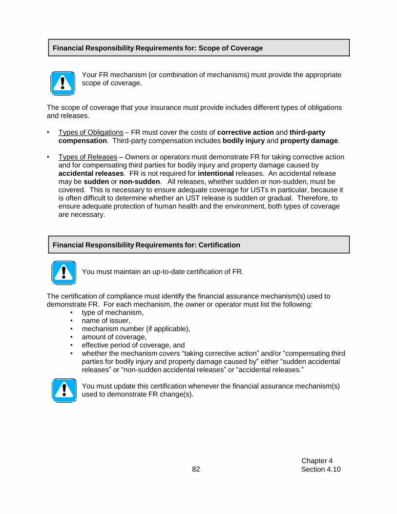
Chapter 4
Section 4.10 82
Financial Responsibility Requirements for: Scope of Coverage
Your FR mechanism (or combination of mechanisms) must provide the appropriate scope of coverage.
The scope of coverage that your insurance must provide includes different types of obligations and releases.
• Types of Obligations – FR must cover the costs of corrective action and third-party
compensation. Third-party compensation includes bodily injury and property damage. • Types of Releases – Owners or operators must demonstrate FR for taking corrective action
and for compensating third parties for bodily injury and property damage caused by accidental releases. FR is not required for intentional releases. An accidental release may be sudden or non-sudden. All releases, whether sudden or non-sudden, must be covered. This is necessary to ensure adequate coverage for USTs in particular, because it is often difficult to determine whether an UST release is sudden or gradual. Therefore, to ensure adequate protection of human health and the environment, both types of coverage are necessary.
Financial Responsibility Requirements for: Certification
You must maintain an up-to-date certification of FR.
The certification of compliance must identify the financial assurance mechanism(s) used to demonstrate FR. For each mechanism, the owner or operator must list the following:
• type of mechanism, • name of issuer, • mechanism number (if applicable), • amount of coverage, • effective period of coverage, and • whether the mechanism covers “taking corrective action” and/or “compensating third
parties for bodily injury and property damage caused by” either “sudden accidental releases” or “non-sudden accidental releases” or “accidental releases.”
You must update this certification whenever the financial assurance mechanism(s) used to demonstrate FR change(s).

Chapter 4
Section 4.10 83
Financial Responsibility Requirements for: Records and Reporting
You must maintain the appropriate records.
• In addition to the certification of FR, you must keep evidence of all financial assurance mechanisms used.
• You must maintain the evidence of all financial assurance at the UST site or the place of work. Records maintained off-site must be made available upon request of the DEM.
• In all cases, you must maintain a copy of documentation for your FR mechanism as worded in the regulations. Depending upon the mechanism used, various other documentation must be maintained as well.
You must submit appropriate FR documentation to the DEM in the following circumstances:
• Within 30 days after you identify a release from an UST system. • If you fail to obtain alternate coverage when required. • At any time, as requested by the implementing agency.
Checklist for Financial Responsibility for your Facility
Answer the following questions:
Yes
No
1. Do you have an appropriate FR mechanism or combination of mechanisms?
List the FR mechanism(s) that you use at your facility. You may list more than one.
If no, then to return to compliance: Obtain one or more FR mechanism(s).
2. Does your FR mechanism (or combination of mechanisms) provide the appropriate amount of coverage?
If no, then to return to compliance: Obtain the appropriate amount of coverage for FR.
3. Does your FR mechanism (or combination of mechanisms) provide the appropriate scope of coverage?
If no, then to return to compliance: Obtain the appropriate scope of coverage for FR.
4. Do you have a current certificate of FR?
If no, then to return to compliance: Complete a certificate as worded in the Federal Regulations Section 280.111(b)11.
5. Do you have all of your documentation for your FR mechanism (or combination of mechanisms), as specified in the Federal Regulations?
If no, then to return to compliance: Obtain the properly worded documentation.
6. Do you keep all of your FR records at your UST site or at your off-site place of business?
If no, then to return to compliance: Obtain the appropriate records and begin keeping them at your UST site or at your off-site place of business.
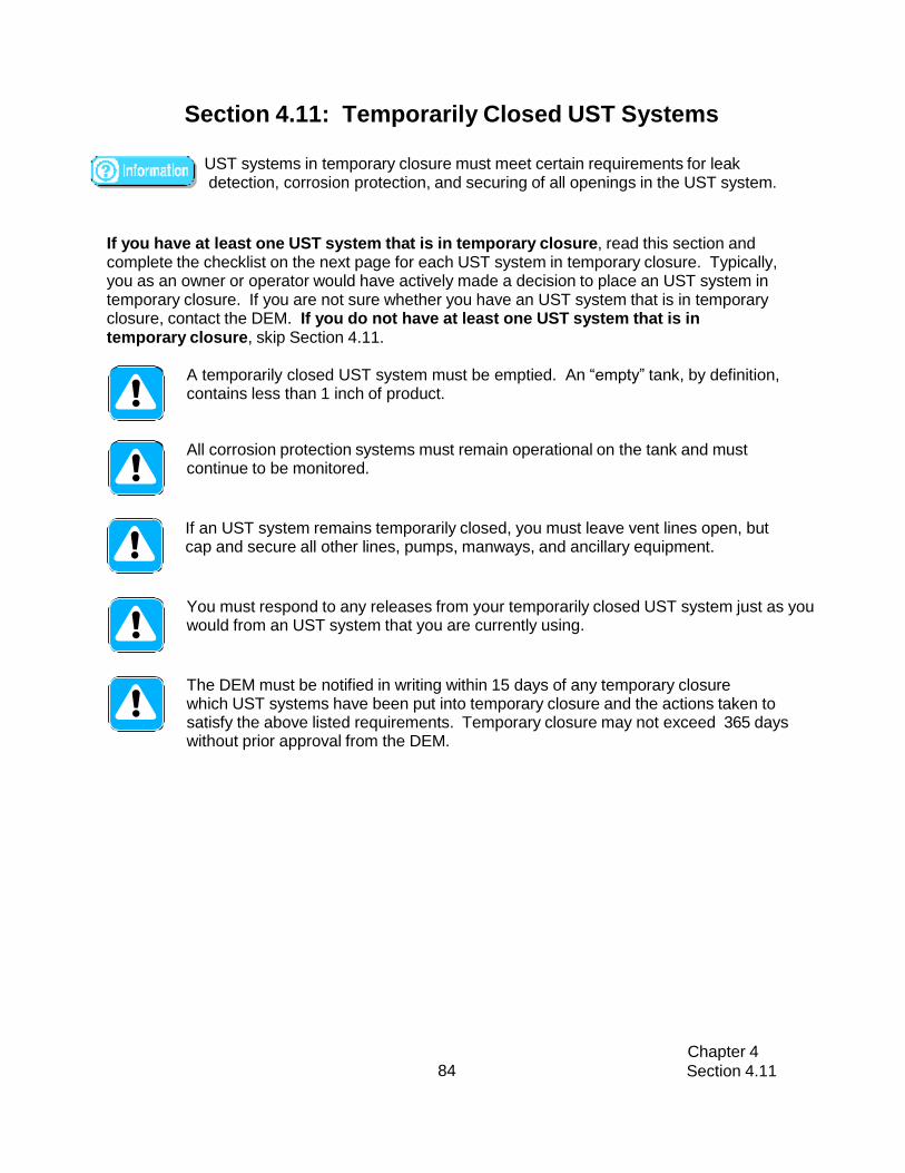
Chapter 4
Section 4.11 84
Section 4.11: Temporarily Closed UST Systems
UST systems in temporary closure must meet certain requirements for leak detection, corrosion protection, and securing of all openings in the UST system.
If you have at least one UST system that is in temporary closure, read this section and complete the checklist on the next page for each UST system in temporary closure. Typically, you as an owner or operator would have actively made a decision to place an UST system in temporary closure. If you are not sure whether you have an UST system that is in temporary closure, contact the DEM. If you do not have at least one UST system that is in temporary closure, skip Section 4.11.
A temporarily closed UST system must be emptied. An “empty” tank, by definition, contains less than 1 inch of product.
All corrosion protection systems must remain operational on the tank and must continue to be monitored.
If an UST system remains temporarily closed, you must leave vent lines open, but cap and secure all other lines, pumps, manways, and ancillary equipment.
You must respond to any releases from your temporarily closed UST system just as you would from an UST system that you are currently using.
The DEM must be notified in writing within 15 days of any temporary closure which UST systems have been put into temporary closure and the actions taken to satisfy the above listed requirements. Temporary closure may not exceed 365 days without prior approval from the DEM.

Chapter 4 Section 4.11 85
Checklist for USTs in Temporary Closure
Circle the UST numbers for tanks in temporary closure.
UST # =
1
2
3
4
5
Questions:
N/A
N/A
N/A
N/A
N/A
Circle the appropriate answer
e the a
ppropr
iate an
swer
Yes (Y) or No (N)
1. Does your temporarily closed UST system contain less than 1 inch of product?
1 Y
1 N
2 Y
2 N
3 Y
3 N
4 Y
4 N
5 Y
5 N
Answer all of the questions for each UST system that you answered NO to this question. You may skip Question 2 for each UST system that you answered YES to this question.
2. Does your temporarily closed UST system meet all the appropriate requirements for release detection in Section 4.7?
1 Y
1 N
2 Y
2 N
3 Y
3 N
4 Y
4 N
5 Y
5 N
If no, either empty the UST or ensure that your UST system meets the appropriate leak detection requirements.
3. Does your temporarily closed UST system meet the requirements for corrosion protection described in Section 4.4?
1 Y
1 N
2 Y
2 N
3 Y
3 N
4 Y
4 N
5 Y
5 N
If no, ensure that your UST system meets the appropriate corrosion protection requirements.
4. Are the vent lines open on your temporarily closed UST system?
1 Y
1 N
2 Y
2 N
3 Y
3 N
4 Y
4 N
5 Y
5 N
If no, open the vent lines.
5. For an UST system in temporary closure, have you capped all lines (except vent lines), pumps, manways, and ancillary equipment on that UST system?
1 Y
1 N
2 Y
2 N
3 Y
3 N
4 Y
4 N
5 Y
5 N
If no, cap all lines (except vent lines), pumps, manways, and ancillary equipment on the temporarily closed UST system.
Y equipment on the temporarily

Chapter 4 Section 4.12 86
Section 4.12: Groundwater Monitoring Wells and Tank Pad
Observation Wells
Groundwater monitoring wells and tank pad observation wells are similar in construction but differ in use. Whereas groundwater monitoring wells are used to detect the presence of regulated substances at the groundwater surface or below, an observation well is used in determining the elevation of the water table.
Groundwater monitoring wells are installed outside the tank excavation in locations that ensure the detection of a potential release from any portion of an UST system. Groundwater monitoring wells are installed as a result of environmental/remediation concerns (to measure the size of spills and the extent/progress of clean-ups). They also may be required for new or replacement UST systems located in environmentally sensitive areas.
Tank pad observation wells are located inside the tank excavation and extend one to two feet below the bottom of the tank. Pad wells are used in situations where knowledge of the water table elevation may be necessary (in tightness testing calculations, for example).
Both types of wells can provide a pathway for the movement of pollutants and contaminants into the water table, and for this reason their proper design, installation, and maintenance are critical.
4.12.1 Construction Standards and Maintenance Requirements
Monitoring wells and pad wells that are finished at ground level:
• Shall be equipped with a labeled and tamper-resistant cover. Labels shall identify them as being groundwater monitoring or observation wells. (Clearly marking the manhole cover with a black equilateral triangle on a white background can serve this purpose.)
• Shall be fitted with a locking gripper cap or plug.
• Cannot be screened to the top, to prevent surface water from infiltrating the wells.
• Shall be maintained to assure the prevention of pollutants from entering into the well. The water in groundwater monitoring wells is required to be bailed and evaluated at least annually.
When required as part of a site investigation at an UST facility, groundwater monitoring wells shall be gauged and sampled on a specified schedule (depending on the extent of contamination) and under the guidance of the RI DEM Leaking Underground Storage Tank Program.

Chapter 4 Section 4.12 87
Wells that are no longer used to gather information on geologic or groundwater properties shall be permanently abandoned in accordance with the RI DEM Rules and Regulations for Groundwater Quality. When groundwater monitoring wells are installed as a condition of approval for
new or replacement UST systems, the following apply:
• Written records of all well check observations are to be maintained as permanent records.
• All owners/operators must promptly investigate and report any evidence of free product in accordance with the RI DEM UST regulations.
Checklist for Groundwater Monitoring Wells & Tank Pad Observation Wells
GROUNDWATER MONITORING WELLS & TANK PAD OBSERVATION WELLS
Number of groundwater monitoring wells at the facility
Number of tank pad observation wells at the facility
Is each well labeled to identify it as a groundwater monitoring well or a tank pad observation
well? Y / N
Is each well equipped with a road box and gripper cap? Y / N
Is each well equipped with a pipe that is NOT screened to the top? Y / N
Is each well cap closed tightly and locked? Y / N
Is the area surrounding the well cap dry and free of standing water? Y / N
Do you have records of groundwater monitoring well checks for the past 3 years? Y / N
If you answered no to any of the questions, fill out a Return-to-Compliance Plan and submit it with your Certification of Compliance form. A Return to Compliance Plan can be found in the accompanying forms booklet.

Chapter 4 Section 4.13 Section 4.14
88
Section 4.13: Mandatory Deadline for Permanent Closure of Single-Walled UST Systems (Tanks and/or Piping)
With the exception of USTs that contain fuel oil that is consumed on-site solely for heating purposes, as well as holding tanks that serve floor drains or other piping outlets, all existing tank and piping systems without secondary containment shall be permanently closed as follows:
• Single-walled tanks and/or piping installed before May 8, 1985 must be permanently closed by December 22, 2017.
• Single-walled tanks and/or piping installed between May 8, 1985 and July 20, 1992 must be permanently closed within 32 years of the date of installation.
Section 4.14: Delivery Prohibition
The Director shall classify all USTs located at a facility as ineligible for delivery, deposit, or acceptance of regulated substances or hazardous materials, after providing written notice and within seven (7) days of determining that one or more underground storage tanks at the facility has one or more of the following violations:
• Failure to have the required spill prevention equipment installed
• Failure to have the required overfill prevention equipment installed
• Failure to have the required leak detection equipment installed
• Failure to have the required corrosion protection equipment installed
The Director may classify all USTs located at a facility as ineligible for delivery, deposit, or acceptance of regulated substances or hazardous materials, if the owner/operator fails to complete corrective action and submit documentation within 60 days following written notice from the Department of one or more of the following violations:
• Failure to properly operate and/or maintain leak detection equipment, perform tank or pipeline tightness testing, and/or compile inventory control records
• Failure to properly operate and/or maintain spill protection, overfill prevention, or corrosion protection equipment
• Failure to maintain Financial Responsibility and the Regulations promulgated under the “Rhode Island Underground Storage Tank Financial Responsibility Act”
• Failure to register or maintain registration including payment of all required fees; or
• Failure to obtain or maintain required certification for Class A, Class B and/or Class C operator(s)

Chapter 4 Section 4.14 89
Upon classification of an UST system as ineligible for delivery, deposit, or acceptance of regulated substances or hazardous materials, the Department shall determine and record the inventory of regulated substances or hazardous materials remaining in each of the USTs located at the facility and a red tag shall be affixed by the Department to the fill pipe(s) of all USTs located at the facility. The tag or device must be:
• Located on the fill pipe of the UST;
• Affixed in a manner that it is easily and immediately visible to the product deliverer; and
• Affixed in manner that it cannot be removed and reattached without obvious visual evidence.
No owner, operator, product deliverer or other person shall deliver, deposit, or accept regulated substances or hazardous materials into an UST which has a red tag affixed to the fill pipe.
USTs that are not brought into compliance, including submission of all required notification and documentation to the Department within 30 days after a red tag has been affixed, shall be immediately placed into temporary closure. USTs that are not brought into compliance, including submission of all required notification and documentation to the Department within 180 days after a red tag has been affixed, shall be immediately permanently closed.

Chapter 4 Section 4.15 90
Section 4.15: Operator Training
According to EPA 40 CFR 280, an UST operator is any person in control of or having responsibility for the daily operation of the UST system.
Effective August 1, 2012, all UST facilities shall have operators that are trained and certified according to the requirements of the RI DEM Rules and Regulations For Underground Storage Facilities Used For Regulated Substances and Hazardous Materials. All facilities shall have three classes of operators: A, B, and C. After August 1, 2012, all new Class A and Class B operators shall be trained and certified within 30 days of assuming responsibility for an UST facility.
Class A Operator Description: The Class A operator is an individual who has the primary statutory and regulatory responsibility for maintenance and operation of the UST facility. This individual shall be trained to have an understanding of the statutory and regulatory requirements that relate to the permitting of the facility, including: financial responsibility; spill containment; overfill protection; release detection; corrosion protection; emergency response; product compatibility; notification requirements; release and suspected release reporting; temporary and permanent closure requirements; reporting and recordkeeping requirements; and operator training requirements.
General Requirements for a Class A operator: • Ensure proper operation and maintenance of the UST system. • Ensure proper record keeping. • Ensure records can be made available to the Department during inspections or
upon request. • Ensure a proper response to emergencies caused by releases or spills from UST
systems. • Make financial responsibility documents available upon request to the
Department. • Ensure all UST registration fees are paid to date. • Ensure that the facility has a certified Class B and a trained Class C operator(s). • Ensure that the Class C that the Class C operators are trained to respond to
emergencies caused by releases or spills from the UST system. • Notify the Department of changes to designated Class A and B operators at a
UST facility and submit updated forms as necessary. • Be immediately available for consultation by telephone when the facility is
operating. • Be on-site within 24 hours of a request to respond to the facility by emergency
response personnel or the Department, or within a timeframe approved by the Department.
• Complete an on-site inspection every month and complete the Department monthly inspection checklist (this may also be conducted by a Class B operator). This inspection must include:

Chapter 4 Section 4.15 91
o Investigating unusual operating conditions o Verifying that all containment basins are clean, empty, and in good
condition o Ensuring that the overfill prevention device is present and operational
Class B Operator Description: The Class B operator is an individual who shall implement the daily on-site operation and maintenance of an UST system(s). This individual shall be trained to have a practical and regulatory understanding of the components of an UST system and its proper operation, including: spill containment; overfill prevention; release detection; corrosion protection; emergency response; and product compatibility.
General Requirements for a Class B operator:
• Ensure that all applicable sections in the DEM UST regulations are met including, but not limited to; spill containment, overfill prevention, leak detection (including inventory control), corrosion protection, and UST system testing.
• Notify the Department of changes to designated Class A and Class B operators at a UST facility and submit updated forms as necessary.
• Ensure that the Class C operators are trained to respond to emergencies caused by releases or spills from the UST system.
• Maintain the list of trained Class C operators with training dates and names of the Class A and/or Class B operator who provided the training.
• Be available for consultation by telephone when the facility is operating.
• Be available within four hours of a request to respond to the facility by emergency response personnel or the Department, or within a timeframe approved by the Department. Ensure that someone is designated to be on site for compliance inspections.
• Complete an on-site inspection every month and complete the Department monthly inspection checklist (this may also be conducted by a Class A operator). This inspection must include:
o Investigating unusual operating conditions o Verifying that all containment basins are clean, empty, and in good
condition o Ensuring that the overfill prevention device is present and operational
Class C Operator Description: The Class C operator is an individual who is an employee and is, generally, the first line of response to events indicating emergency conditions. This individual shall be trained to recognize and respond to emergencies caused by releases or spills from the UST system, and be familiar with the facility layout and with reading alarm enunciator panels.
General Requirements for Class C operators:
• Class C operators must be trained prior to assuming the responsibilities of a Class C operator.
• Be present at the facility during all operating hours.
• Control or monitor the dispensing or sale of regulated substances from the UST system.
• Properly respond to alarms or releases.

Chapter 4 Section 4.15 92
• Notify the Class A or Class B operator and appropriate emergency responders when there is a spill or other emergency.
• Be knowledgeable about and have access to the location of UST facility records.
4.15.1 Operator Training and Certification
“Operator Training” is a program mandated by the Federal Government, which provides individuals with knowledge essential to UST operation, and ensures:
• Knowledge regarding the operation and maintenance of underground storage tank systems.
• The proper response to alarms and emergencies caused by spills or releases from an UST system.
• The presence of trained and certified operators at all UST sites.
All A and B operators must pass an International Code Council (ICC) exam approved by the Department. Certification as a result of passing this exam will be good for five (5) years provided the facility remains in compliance with the regulations.
• A copy of this certification must be submitted to the Department with the appropriate registration form for Class A and Class B operators to remain in compliance.
Class C operators must be trained every two (2) years, by a Class A or B operator. Class C operators must be trained before assuming the role designated by the owner.
Facilities that do not normally have employees on-site (e.g., state / municipal unmanned fueling facilities) must have a sign posted that lists both the name and telephone number of the Class A operator, the Class B operator, the facility owner/ operator, 911, and local emergency responders, and advises persons to call these numbers in the event of a spill or other emergency. This sign must be posted so that if an emergency occurs the person fueling the vehicle or filling the USTs can read it.
Before operating without having a Class C operator present during all operating hours, these facilities must be approved by the DEM in writing. These facilities must still have trained A, B and C operators. A designated person(s) must be available to respond to emergencies when the owner or operator is contacted.
Any other questions pertaining to UST operator certification may be directed to Raymond Taylor at 401-222-2797 x7705 or e-mail at [email protected].

Chapter 4 Section 4.15 93
4.15.1.1 Retraining and Re-Certification
If a facility is not in compliance with these regulations at the time of a Department or EPA conducted UST compliance inspection, then the Class A and/or Class B operators are required to be retrained and re-certified within 60 days as specified below:
• Class A operators shall be retrained and re-certified if any facility for which they provide oversight is determined by the Department to be significantly out of compliance with the requirements of these regulations for which a Class A operator is responsible
• Class B operators shall be retrained and re-certified if any facility for which they provide oversight is determined by the Department to be significantly out of compliance with the requirements of these regulations for which a Class B operator is responsible
• Class A and B operators that require retraining shall be retrained and re-certified within 30 days of the date of the Department’s letter of non-compliance and shall submit a copy of the recertification to the Department immediately.
4.15.2 Walk-Through Inspections and Maintenance
Class A or Class B operators are responsible for performing a walk-through inspection at least once a month to make sure the essential equipment is working properly, there is no deterioration of rubberized components, and there are release response supplies on hand. When performing a walk-through inspection the following should be checked:
• Release detection system (ATG monitor)
• Spill buckets
• Overfill Alarm (if there is one on site)
• Impressed Current Cathodic Protection System (if there is one on site)
• Fill and monitoring ports
• Spill and overfill response supplies
In addition, good UST site management should also include a quick visual check of the following:
• STP pumps and piping sumps
• Dispenser hoses, nozzles, and breakaways
• Under dispenser plumbing and containment
• Monitoring well labeling and maintenance
• Verify emergency contact numbers are current, posted, and everyone at the UST facility is familiar with the list of contacts
Chapter 4 Section 4.15 94
The Class A or B operator must complete a monthly inspection form as part of the walk-through inspection. (A copy of the monthly inspection checklist can be found in Appendix K.) Results of these inspections shall remain on file at the facility for three (3) years and be made available at the time of a Department inspection.
Periodic inspections should focus on storage system components that operate in difficult environments, have moving parts, or are subject to abuse. Factors that may influence the frequency of inspections include monthly throughput, climatic conditions, sensitivity of the environment adjacent to the storage system, applicable environmental rules and regulations, manufacturer’s recommendations, experience with component performance, or following a customer’s complaint of slow-flowing fuel or complaints concerning a nozzle shutoff failure.
4.15.3 Record Keeping
The following documents must be maintained by UST operators according to the RI DEM UST regulations:
• Records of UST system repairs for the remaining operating life of the UST
• Records of operation of corrosion protection equipment
• Results of site investigations and remedial response activities
• Records of compliance with leak detection requirements
• Results of sampling, testing, or monitoring
• Equipment warranties and manufacturer’s checklists

Chapter 5
Section 5.1
95
Chapter 5: Stage I Vapor Recovery Systems
Section 5.1: Stage I Vapor Recovery
5.1.1 Overview – Stage I
Stage I refers to the control of vapors during the transfer of gasoline from the cargo tank to the gasoline dispensing facility. Stage I vapor recovery systems control emissions during delivery and storage of gasoline at the gasoline dispensing facility.
Gasoline is delivered by cargo tank truck from a bulk terminal to a stationary storage tank at a gasoline dispensing facility. During gasoline delivery, emissions are controlled by diverting the displaced gasoline vapor from the storage tank into the tanker compartment of the vehicle unloading gasoline. The captured vapor is then transported back to the terminal for processing by condensation, adsorption or incineration.
Vapor recovery is a control strategy developed to collect vapors generated during the transfer of gasoline in the marketing and distribution process. Vapors are created due to the high volatility of gasoline at atmospheric conditions; there is a strong tendency for gasoline to evaporate. When liquid evaporates in a closed system, molecules in the vapor state have a tendency to strike and condense on the surface of the liquid. At a point when the rates of evaporation and condensation are equal, a state of equilibrium is achieved. When a system is in equilibrium the concentration of vapor is highest near the surface of the liquid and decreases with the height above the surface. The pressure exerted by vapor in equilibrium with its liquid is referred to as vapor pressure.
Gasoline at a dispensing facility may be stored in either underground or aboveground storage tanks. Most commonly, the storage tanks are underground, with gasoline being unloaded by gravity.
Types of systems used are:
• Dual, or two-point system – the filling and vapor recovery provisions on the storage tank consist of two attachment points (one for liquid delivery and one for vapor return to the truck), which is the most commonly found system
• Coaxial, or single point system – the filling and vapor recovery provisions consist of a single attachment point.
Both systems must provide a liquid and vapor tight seal during delivery, and at all other times.
Stage I vapor recovery requires that vapors be collected in the cargo tank as product is delivered into the underground storage tank. Most gasoline dispensing facilities have more than one underground storage tank to store the different grades of gasoline that are sold. Each underground storage tank or manifolded storage tanks have fittings for gasoline delivery and vapor recovery.
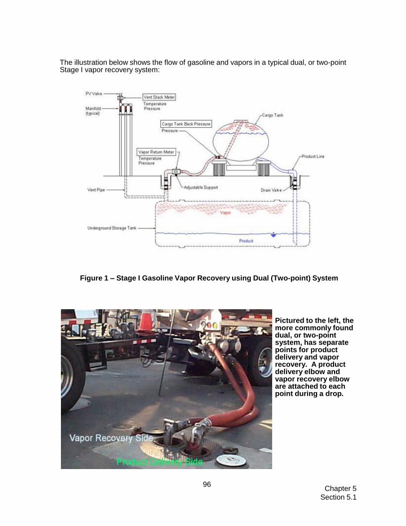
Chapter 5
Section 5.1
96
The illustration below shows the flow of gasoline and vapors in a typical dual, or two-point Stage I vapor recovery system:
Figure 1 – Stage I Gasoline Vapor Recovery using Dual (Two-point) System
Pictured to the left, the more commonly found dual, or two-point system, has separate points for product delivery and vapor recovery. A product delivery elbow and vapor recovery elbow are attached to each point during a drop.

Chapter 5
Section 5.1
97
As shown on the previous page, the Stage 1 dual, or two-point vapor recovery system, consists of two separate spill containment boxes: one for gasoline delivery and the other for vapor collection. Product is delivered using one elbow, and vapor recovered through another elbow. A cross section of a dual system is shown in the illustration below:
Figure 2 – Stage I Dual (or two-point) Vapor Recovery System
In the dual system, gasoline is delivered to the facility’s stationary storage tank, and displaced gasoline vapor is recovered through a riser pipe on the tank.
Gasoline is delivered through a submerged drop tube, while the vapor is forced up a riser pipe from the vapor space (i.e. ullage – free space above liquid product in the gasoline storage tank). The dual system for underground tanks is enclosed in a manhole that is raised slightly above the surrounding pavement, in order to minimize the infiltration of surface water. Each riser pipe is encased in a spill container (i.e., spill bucket), and fitted with an adaptor and dust cap. Many of the gasoline spill buckets contain a valve through which accumulated gasoline can be drained back into the storage tank manually.
A Stage I coaxial (or single-point) system, which may be found on older gasoline dispensing facilities, utilizes a single containment box for the delivery of gasoline, and for the recovery of vapors. Product is delivered and vapor recovered using the same elbow. A cross section of a coaxial system is shown in the illustration on the following page:

Chapter 5
Section 5.1
98
Figure 3 – Typical Stage I Coaxial Vapor Recovery System
The picture to the left shows a coaxial, or single- point system. Concentric tubing from the UST allows for recovery of vapors via one pipe, as product is delivered via the other. Product is delivered and vapor recovered using the same elbow.
Chapter 5
Section 5.1
99
5.1.2 Rhode Island Regulations
Stage I Vapor Recovery is addressed in the DEM “Title 250, Chapter 120, Subchapter 5, Part
11 - Petroleum Liquids Marketing And Storage”. The complete regulation is posted on the
RI Secretary of State website at: https://rules.sos.ri.gov/regulations/part/250-120-05-11
5.1.3 Requirements
As of December 25, 2013, the requirements for Stage I and Stage II vapor recovery systems in the Rhode Island Department of Environmental Management’s (RI DEM’s) 250-120-05-11 have changed. The most important changes are listed below.
• All GDFs shall be equipped with a CARB-certified Enhanced Vapor Recovery (EVR) Stage I pressure-vacuum (PV) vent valve.
• All GDFs, except for facilities with co-axial tank systems, shall be equipped with CARB-certified EVR Stage I rotatable product and vapor adaptors.
• All GDFs that begin operation or install a fuel storage tank on or after December 25, 2013 must have a CARB-certified EVR Stage I vapor control system or a Stage I vapor control system made up of EVR parts when the facility starts-up following that installation.
• After December 25, 2013, any part of a Stage I system that is replaced must be replaced with a CARB-certified EVR Stage I part. Stage I parts that are not working properly must be replaced immediately.
• By December 25, 2020, all GDFs must have installed a CARB-certified EVR Stage I system or a Stage I system made up of EVR components.
• Aboveground storage tanks are exempt from the requirement to install a rotatable product adaptor or another EVR Stage I part if that installation is not technically feasible.
• A stainless steel UL-approved spill container that is not attached to the Stage I system may be used in the place of an EVR spill container.
• GDFs that do not have Stage II systems must visually inspect their Stage I systems weekly and must perform the following tests of the Stage I system at least once every twelve months:
o A Pressure Decay 2-inch Test (CARB TP-201.3)
o A Vapor Tie Test (CARB TP-201.3C)
o A Pressure/Vacuum Vent Valve Test (CARB TP-201.1E)
o A Static Torque Rotatable Adaptor Test (CARB TP-201.1B) for GDFs with EVR rotatable product adaptors and/or vapor adaptors, and
o For GDFs with a Stage I EVR system, either a Leak Rate of Drop Tube/Drain Valve Assembly Test (CARB TP-201.1C) or a Leak Rate of

Chapter 5
Section 5.1
100
Drop Tube/Overfill Prevention Devices Test (CARB TP-201.1D)
o GDFs must notify RI DEM of the date that testing will be conducted at least seven (7) days before testing and must certify in writing within fifteen (15) days of the test that testing has been completed. The certification must be signed by the owner or operator of the facility and must include a list of Stage I EVR components operating at the facility and the results of the tests listed above. Test results must be signed and certified as accurate by the person who conducted the tests.
5.1.3.1 Exemptions
The Stage I Vapor Recovery requirements apply to all gasoline dispensing facilities except the following:
• Stationary gasoline storage vessels of less than 550 gallons capacity used exclusively for the fueling of implements of husbandry, provided the containers are equipped with submerged fill pipes
• Stationary storage vessels located at a gasoline dispensing facility with a capacity of less than 2,000 gallons, which is in place before July 1, 1979
• Any stationary storage vessels located at a gasoline dispensing facility with a capacity of 250 gallons or less which is installed after the effective date of January 10, 2019,
• Any gasoline dispensing facility that is solely serviced by account trucks owned or under the control of bulk gasoline plants that are exempt from the Bulk Gasoline Plants section of Part 11 (250-120-05-11).
5.1.3.2 Control Systems
Except in situations as noted above, no person may transfer or allow the transfer of gasoline from any delivery vessel into any stationary storage vessel, unless the stationary storage vessel is equipped with a submerged fill pipe, and the vapors displaced from the storage vessel during filling are processed by a vapor control system. The vapor control system shall be subject to the following conditions:
1. All vapor connections and lines on the storage tank shall be equipped with
closures that seal upon disconnect,
2. The vapor line from the gasoline storage tank to the gasoline cargo tank shall be vapor-tight, as defined in Part 11.5(A)(24).
3. The Stage I vapor control system shall be designed such that the pressure in the tank does not exceed eighteen (18) inches water pressure or 5.9 inches water vacuum during product transfer,
4. The vapor recovery and product adaptors and the method of connection with the delivery elbow shall be designed so as to prevent the over-tightening or loosening of fittings during normal delivery operations.
5. If a gauge well separate from the fill tube is used, it shall be provided with a submerged drop tube that extends the same distance from the bottom of the storage tank as specified in Part 11.

Chapter 5
Section 5.1
101
6. Liquid fill connections shall be equipped with vapor-tight caps.
5.1.3.3 Gasoline Storage Vessel (Tank) Requirements Gasoline Delivery Vessel (Cargo Tank) Requirements
The Gasoline Delivery Cargo Tank is subject to the conditions outlined below:
1. The delivery cargo tank must be designed and maintained to be vapor tight at all times, and
2. The vapor-laden delivery vessel may be re-filled only at: a. Bulk gasoline terminals complying with the section of Part 11
pertaining to Bulk Gasoline Terminals b. Bulk gasoline plants complying with the section of Part 11
pertaining to Bulk Gasoline Plants
Each owner of a gasoline storage vessel (tank) and gasoline delivery vessel (cargo tank) shall:
1. Purchase and install all necessary control systems and make all necessary
process modifications to comply with vapor control system and delivery cargo tank requirements described above
2. Provide instructions to the operator of the gasoline dispensing facility utilizing a
Stage I vapor control system as required in Part 11 describing necessary maintenance operations and procedures for prompt notification of the owner in case of any malfunctions of the control system, and
3. Repair, replace or modify any worn out or malfunctioning component or element of design
5.1.3.4 Operators of Gasoline Dispensing Facilities
Operators of gasoline dispensing facilities with required vapor recovery systems must:
1. Maintain and operate the control system in accordance with the specifications
and the operating and maintenance procedures specified by the owner of the vapor control system, and
2. Conduct Weekly Visual Inspections of the Stage I system components, and
3. Notify the owner of the vapor control system of any scheduled maintenance or malfunction requiring replacement or repair of major components in the system

Chapter 5
Section 5.1
102
5.1.3.5 Records
Written weekly Stage I inspection records must be maintained and kept at the facility for a period of five (5) years.
Maintain the following records for a period of five (5) years, and should be accessible for review by representatives of the Department or the EPA on request: 1. The dates and results of weekly visual inspections;
2. The dates and results of tests performed outlined in section 5.1.3. or
11.9.2(G)(2) of Part 11,
3. Identification of Stage I vapor control system components that are replaced, the replacement components installed, and dates of such replacements, and
4. Gasoline throughput quantities.
5.1.3.6 Compliance & Compliance Test Methods
Facilities subject to Stage I vapor recovery requirements are referred to 250-120-05- Part 11, 11.9.2(G)(1-5) for Compliance and Compliance Test Methods requirements.
5.1.4 Stage I Weekly Inspection Information
Weekly inspections of Stage I vapor recovery systems must be conducted, as required by Part 11 (11.9.2.G) The vapor recovery system information that follows is provided to assist owners and operators with properly identifying components of their systems,and completing the required weekly visual checks. The items that need to be inspected:
• Fill/drybreak caps – check to assure caps are fully intact and operational, sealing properly, have no cracks or damage
• All gaskets – check to assure that all gaskets in caps and drop tubes are intact, have no cracks
• Drybreaks (vapor recovery adaptors) – check to assure that drybreaks are intact and providing a tight, uniform seal, and that rubber gaskets are sealing properly and not damaged,
• Fills and Adapters – check to assure that all adaptors are tight on the riser
• Spill containment plungers – check to assure that all are intact, with no vapor emissions found.
• Drop tubes – check to assure that they are installed in all gasoline tanks.
• Drop tubes – check to assure that they are intact, in the proper position, not dented.
The regulation requires that weekly inspections are conducted and that written weekly

Chapter 5
Section 5.1
103
inspection records be kept at the facility for a period of five (5) years.
5.1.5 Stage I Vapor Recovery Components
All components and replacements parts of the Stage I Vapor Recovery System must be certified by the California Air Resources Board (CARB).
The Phase I Vapor Recovery System typically consists of the following components:
• Spill Containment Box – containment manhole, usually equipped with a drain
valve, installed to and around the storage tank product riser pipe
• Riser – 3” or 4 “ diameter pipe mounted to the top of the UST, with each riser fitted with an adaptor and dust cap
• Adaptor (Coupler) – a fitting on each riser pipe inside a spill container, allows a leak- proof seal with the delivery elbow of the cargo tank.
• Drop Tube – fill pipe through which product is delivered into a storage tank from a cargo tank
• Dust Cap – a cover, with a gasket, that seals the top of either a Stage I fill adapter or a Stage I drybreak/poppet
• Drain Valves – valves located at the bottom of a spill container to drain accumulated liquid into the UST
• Dry Break (Poppet) – a spring-loaded valve that prevents vapor from escaping through the vapor recovery riser pipe opening of a storage tank
• Pressure/Vacuum (PV) Relief Valves – dual purpose valves that automatically prevent excessive positive or negative pressure in the tank or pipe to which it is connected
• Overfill Protection Device – a device, added to a storage tank, to prevent overfilling and spillage during a fuel drop by a cargo tank
The image to the left shows the location of some Phase I Vapor Recovery System Components
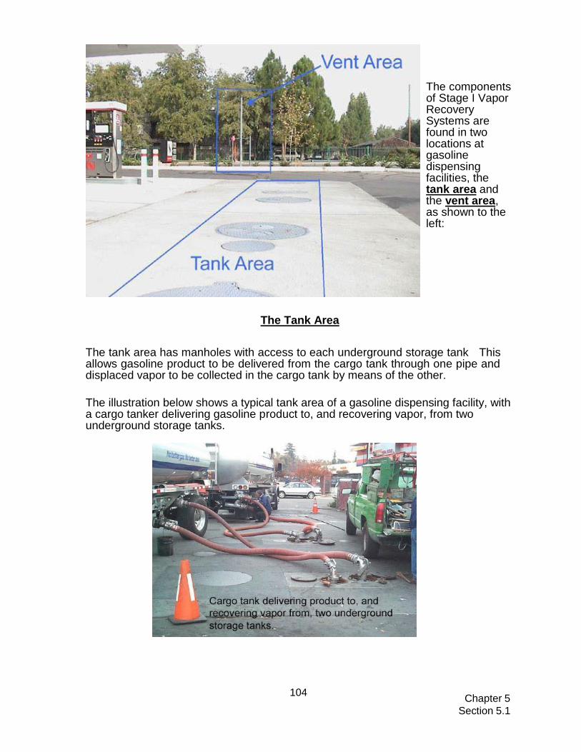
Chapter 5
Section 5.1
104
The components of Stage I Vapor Recovery Systems are found in two locations at gasoline dispensing facilities, the tank area and the vent area, as shown to the left:
The Tank Area The tank area has manholes with access to each underground storage tank This allows gasoline product to be delivered from the cargo tank through one pipe and displaced vapor to be collected in the cargo tank by means of the other.
The illustration below shows a typical tank area of a gasoline dispensing facility, with a cargo tanker delivering gasoline product to, and recovering vapor, from two underground storage tanks.

Chapter 5
Section 5.1
105
The illustration below shows both product delivery and vapor recovery sides of a tank, with some of the components labeled. In the dual, two point system, as shown in the illustration, the manhole above the underground storage tank contains two tank risers. One riser is for delivering product from the cargo tank to the underground tank. The other riser, which includes the vapor recovery adapter (drybreak), is for delivering displaced vapor from the underground tank back to the cargo tank.
Stage I Product Delivery
The schematic to the left shows the product delivery piping.
Product is delivered to the UST from the cargo tank via a submerged pipe called a drop tube.
The drop tube is guided into the UST by the tank riser pipe.

Chapter 5
Section 5.1
106
The Vent Area
Storage tanks have vent pipes equipped with pressure/vacuum (P/V) relief valves. P/V valves are designed to open at specified positive and negative pressures, so that the tank is protected from physical damage or permanent deformation caused by routine increases in internal pressure or vacuum. They also provide a safeguard in the event any pipes become blocked or inoperable. Additionally, the P/V valve setting on the tank vent is such that it acts as a flow control device that preferentially allows displaced vapors to pass to the tanker compartment during a drop.
Tanks need to breathe because of volume fluctuations due to temperature changes, barometric pressure changes, and variations in the vapor/liquid ratio during refueling. When the internal pressure exceeds the valve design setting, the valve opens to vent the excess pressure to the atmosphere. When the vacuum exceeds the design setting, the valve opens to allow air to flow into the tank and relieve the excess vacuum condition.
The vent area contains one to three product vent lines, usually one vent for each underground storage tank. Each vent line must be capped with a pressure/vacuum relief (P/V) valve, as shown in the illustration below on the right, or manifolded with other lines below ground, or as shown in the illustration on the left.
Thanks to California Air Resources Board, Stationary Source Division, Compliance Assistance Program Vapor Recovery Interactive CD, August 2002; CARB Interactive CD w/ Stage I & II
Questions about Stage I/II requirements should be addressed to Brianna Seltzer at
(401)222-2808, ext. 2427 or by e-mail at [email protected].

A-1
Appendix A: For More Information This section identifies UST program contacts and other resources that can help answer your questions and provide you with information about good UST management.
State Regulatory Agency Information RI DEM RI DEM Office of Waste Management Office of Customer & Technical Assistance 235 Promenade Street 235 Promenade Street Providence, RI 02908 Providence, RI 02908 (401) 222-2797 (401) 222-6822
WEB SITE: www.dem.ri.gov
Internet Resources
Government Links • U.S. Environmental Protection Agency’s Office of Underground Storage Tanks
Home Page: http://www.epa.gov/oust. To go directly to the compliance assistance section of the Home page go to: http://www.epa.gov/swerust1/cmplastc/index.htm. To go directly to EPA’s listing of publications, go to: http://www.epa.gov/swerust1/pubs/index.htm.
Professional And Trade Association Links • American Petroleum Institute (API): http://.api.org/ • American Society of Testing and Materials (ASTM):
http://www.astm.org/index.html • Fiberglass Tank and Pipe Institute (FTPI): http://www.fiberglasstankandpipe.com • NACE International – The Corrosion Society: http://.nace.org/ • National Fire Protection Association (NFPA) : http://.nfpa.org • Petroleum Equipment Institute (PEI): http://.pei.org • Steel Tank Institute (STI): http://.steeltank.com/ • Underwriters Laboratories (UL): http://www.ul.com
Free Informative Publications Available The publications listed on the next pages are free and available from the U.S. Environmental Protection Agency (EPA). You can access these publications via EPA’s website or you can call, write to, or fax EPA. You can download, read, or order documents from http://www.epa.gov/swerust1/pubs/index.htm. To order free copies or ask questions, call EPA’s toll-free RCRA/Superfund Hotline at 800-424-9346 or call EPA’s publication distributor’s toll- free number at 800-490-9198 or fax 513-489-8695. You can also write and ask for free publications by addressing your request to EPA’s publication distributor: National Service Center for Environmental Publications (NSCEP), Box 42419, Cincinnati, OH 45242. Fax-on- Demand allows you to call 202-651-2098 on your fax to access over 220 UST documents.
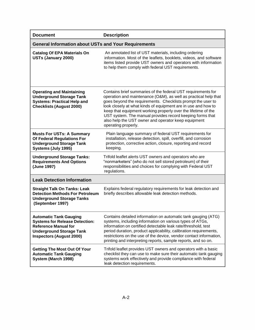
A-2
Document Description
General Information about USTs and Your Requirements
Catalog Of EPA Materials On An annotated list of UST materials, including ordering
USTs (January 2000) information. Most of the leaflets, booklets, videos, and software items listed provide UST owners and operators with information to help them comply with federal UST requirements.
Operating and Maintaining Contains brief summaries of the federal UST requirements for
Underground Storage Tank operation and maintenance (O&M), as well as practical help that
Systems: Practical Help and goes beyond the requirements. Checklists prompt the user to
Checklists (August 2000) look closely at what kinds of equipment are in use and how to keep that equipment working properly over the lifetime of the UST system. The manual provides record keeping forms that also help the UST owner and operator keep equipment operating properly.
Musts For USTs: A Summary Plain language summary of federal UST requirements for
Of Federal Regulations For installation, release detection, spill, overfill, and corrosion
Underground Storage Tank protection, corrective action, closure, reporting and record
Systems (July 1995) keeping.
Underground Storage Tanks: Trifold leaflet alerts UST owners and operators who are
Requirements And Options “nonmarketers” (who do not sell stored petroleum) of their
(June 1997) responsibilities and choices for complying with Federal UST regulations.
Leak Detection Information
Straight Talk On Tanks: Leak Explains federal regulatory requirements for leak detection and Detection Methods For Petroleum briefly describes allowable leak detection methods.
Underground Storage Tanks (September 1997)
Automatic Tank Gauging Contains detailed information on automatic tank gauging (ATG)
Systems for Release Detection: systems, including information on various types of ATGs,
Reference Manual for information on certified detectable leak rate/threshold, test
Underground Storage Tank period duration, product applicability, calibration requirements,
Inspectors (August 2000) restrictions on the use of the device, vendor contact information, printing and interpreting reports, sample reports, and so on.
Getting The Most Out Of Your Trifold leaflet provides UST owners and operators with a basic
Automatic Tank Gauging checklist they can use to make sure their automatic tank gauging
System (March 1998) systems work effectively and provide compliance with federal leak detection requirements.
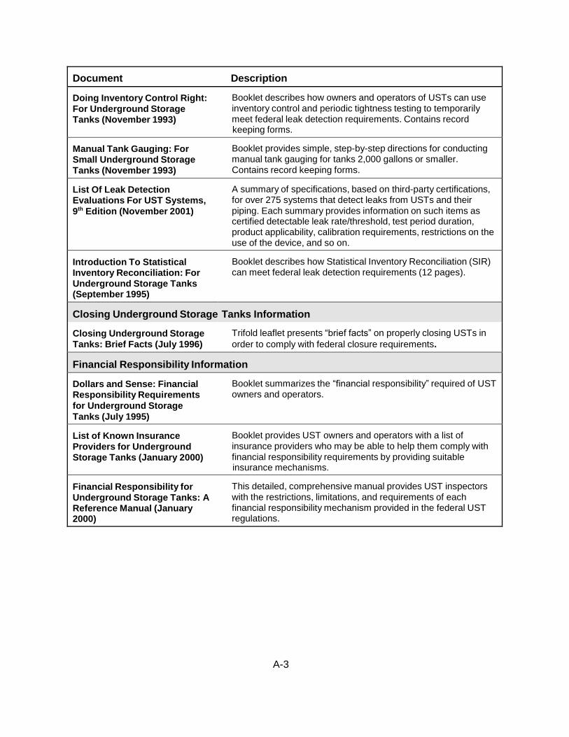
A-3
Document Description
Doing Inventory Control Right: Booklet describes how owners and operators of USTs can use
For Underground Storage inventory control and periodic tightness testing to temporarily
Tanks (November 1993) meet federal leak detection requirements. Contains record keeping forms.
Manual Tank Gauging: For Booklet provides simple, step-by-step directions for conducting Small Underground Storage manual tank gauging for tanks 2,000 gallons or smaller. Tanks (November 1993) Contains record keeping forms.
List Of Leak Detection A summary of specifications, based on third-party certifications, Evaluations For UST Systems, for over 275 systems that detect leaks from USTs and their
9th Edition (November 2001) piping. Each summary provides information on such items as certified detectable leak rate/threshold, test period duration, product applicability, calibration requirements, restrictions on the use of the device, and so on.
Introduction To Statistical Booklet describes how Statistical Inventory Reconciliation (SIR)
Inventory Reconciliation: For can meet federal leak detection requirements (12 pages).
Underground Storage Tanks (September 1995)
Closing Underground Storage
Tanks Information
Closing Underground Storage Trifold leaflet presents “brief facts” on properly closing USTs in Tanks: Brief Facts (July 1996) order to comply with federal closure requirements.
Financial Responsibility Information
ation
Dollars and Sense: Financial Booklet summarizes the “financial responsibility” required of UST Responsibility Requirements owners and operators.
for Underground Storage
Tanks (July 1995)
List of Known Insurance Booklet provides UST owners and operators with a list of
Providers for Underground insurance providers who may be able to help them comply with
Storage Tanks (January 2000) financial responsibility requirements by providing suitable insurance mechanisms.
Financial Responsibility for This detailed, comprehensive manual provides UST inspectors
Underground Storage Tanks: A with the restrictions, limitations, and requirements of each
Reference Manual (January financial responsibility mechanism provided in the federal UST 2000) regulations.

B-1
Appendix B: Sample Placards for Overfill Devices
DELIVERY PERSON — AVOID OVERFILLS
# An overfill alarm is used for overfill prevention at this facility.
# Do not tamper with this alarm in any attempt to defeat its purpose.
# When the tank is 90% full, the overfill alarm sounds and/or a light comes on or flashes.
# If you hear the alarm sound or see the light on or flashing,
STOP THE DELIVERY IMMEDIATELY!
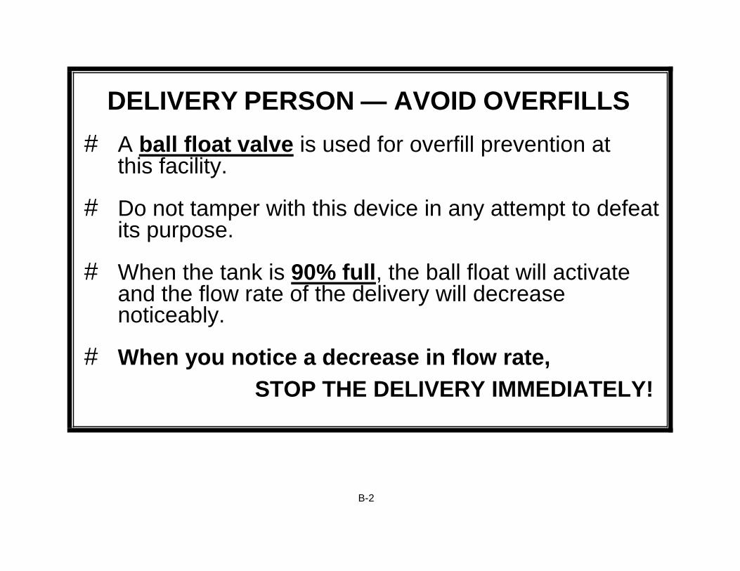
B-2
DELIVERY PERSON — AVOID OVERFILLS
# A ball float valve is used for overfill prevention at this facility.
# Do not tamper with this device in any attempt to defeat its purpose.
# When the tank is 90% full, the ball float will activate and the flow rate of the delivery will decrease noticeably.
# When you notice a decrease in flow rate,
STOP THE DELIVERY IMMEDIATELY!

B-3
DELIVERY PERSON — AVOID OVERFILLS
# An automatic shutoff device is used for overfill prevention at this facility.
# Do not tamper with this device in any attempt to defeat its purpose.
# When the tank is 95% full, the device will activate and slow down, and then stop, the delivery before the tank is overfilled.
# When the automatic shutoff device activates,
STOP THE DELIVERY IMMEDIATELY!

Appendix C: Sample Emergency Numbers List
Important Contact Information
Contact Name Phone #
(401) 222-2797
State UST Agency: Rhode Island DEM (or call the 24 hr Emergency Hotline at (401) 222-3070)
Local UST Agency:
Fire Department:
Ambulance:
Police Department:
Repair Contractor:
Other Contacts:
Release Response Checklist
‘ Stop the release: Take immediate action to prevent the release of more product. Turn off the power to the dispenser and “bag” the nozzle. Make sure you know where your emergency shutoff switch is located. Empty the tank, if necessary, without further contaminating the site.
‘ Contain the spill or overfill: Contain, absorb, and clean up any surface releases. Identify any fire,
explosion or vapor hazards and take action to neutralize these hazards.
‘ Call for help and to report suspected or confirmed releases: Contact your local fire emergency
response authority. Contact the DEM UST Section at (401) 222-2797 immediately. After hours releases may be reported to the DEM 24-hour Emergency Response Hotline at (401) 222-3070.
C-1
Appendix C

D-1
Appendix D: Cathodic Protection Testing Form (for use by a qualified cathodic protection tester)
TEST DATE: / / FACILITY NAME/ID:
NOTE: Provide site sketch as directed on the back of this page. Cathodic Protection (CP) Tester Information:
Name:
Phone Number:
Address:
Testing must be conducted by a qualified CP tester. Indicate your qualifications as a CP tester:
Identify which of the following testing situations applies:
Test required within 6 months of installation of CP system (installation date was / / )
Test required at least every 3 years after installation test noted above
Test required within 6 months of any repair activity – note repair activity and date below:
Indicate which industry standard you used to determine that the Cathodic Protection test criteria are
adequate:
Cathodic Protection Test Method Used (check one)
100 mV Cathodic Polarization Test
-850 mV Test (Circle 1 or 2 below)
1) Polarized Potential (“instant off”)
2) Potential with CP Applied, IR Drop Considered
Note: All readings taken must meet the -850 mV criteria to pass
Other Accepted Method (please describe):
Is the Cathodic Protection System working properly? Yes No (circle one) My signature below affirms that I have sufficient education and experience to be a cathodic protection tester; I am competent to perform the tests indicated above; and that the results on this form are a complete and truthful record of all testing at this location on the date shown.
CP Tester Signature: Date:
Site Sketch: Provide a rough sketch of the tanks and piping, the location of each CP test, and each voltage value obtained (use space below or attach separate drawing). Voltage readings through concrete or asphalt do not provide accurate readings and are

D-2
not acceptable. Perform sufficient testing to evaluate the entire UST system.
If CP System fails a test, you must have a corrosion expert fix the system. If your CP system does not meet the requirements for cathodic protection, you must have a corrosion expert investigate and fix the problem. A corrosion expert has additional training, skills, and certification beyond the corrosion tester who filled out the bulk of this form. A corrosion expert must be 1) accredited/certified by NACE International, the Corrosion Society, as a corrosion specialist or cathodic protection specialist, or 2) a registered professional engineer with certification or licensing in corrosion control. As long as you have the UST, be sure you keep a record that clearly documents what the corrosion expert did to fix your CP system.

Appendix E: Impressed Current 60 Day Inspection Form
FACILITY NAME:
AMP RANGE RECOMMENDED:
VOLTAGE RANGE RECOMMENDED:
Date
Your Name Voltage
Reading Amp
Reading Is Your System Running
Properly? (Yes/No)
• If the rectifier voltage and/or amperage output(s) are outside the recommended operating levels, contact a cathodic protection expert to address the problem.
• Never turn off your rectifier.
• KEEP THIS RECORD FOR AT LEAST 3 YEARS BEYOND THE OPERATIONAL LIFE OF
THE FACILITY
E-1

F-1
Appendix F: Sample 30-Day Leak Detection Monitoring Record (May be used for interstitial monitoring (IM) and automatic tank gauging (ATG))
LEAK DETECTION METHOD:
FACILITY NAME:
Date
Your Name
UST System (Tank & Piping) (Enter “N” for NO LEAK DETECTED or
“Y” for a SUSPECTED OR CONFIRMED RELEASE)
UST #
UST #
UST #
UST #
UST #
If your leak detection system suspects or confirms a release, take appropriate release response
actions. See Section 4.9 of the Workbook for appropriate actions.
KEEP THIS PIECE OF PAPER AND ANY ASSOCIATED PRINTOUTS ON FILE FOR AT LEAST 3
YEARS FROM THE DATE OF THE LAST ENTRY
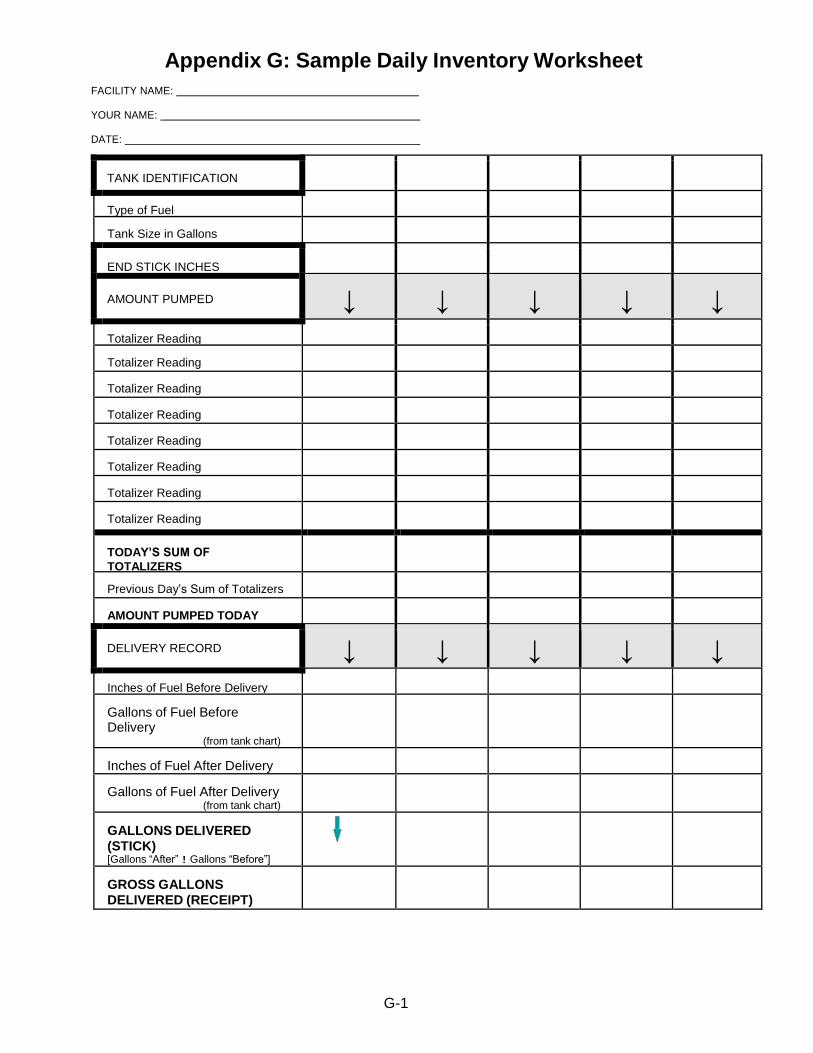
G-1
Appendix G: Sample Daily Inventory Worksheet
FACILITY NAME:
YOUR NAME:
DATE:
TANK IDENTIFICATION
Type of Fuel
Tank Size in Gallons
END STICK INCHES
AMOUNT PUMPED ↓ ↓ ↓ ↓ ↓
Totalizer Reading
Totalizer Reading
Totalizer Reading
Totalizer Reading
Totalizer Reading
Totalizer Reading
Totalizer Reading
Totalizer Reading
TODAY’S SUM OF
TOTALIZERS
Previous Day’s Sum of Totalizers
AMOUNT PUMPED TODAY
DELIVERY RECORD ↓ ↓ ↓ ↓ ↓
Inches of Fuel Before Delivery
Gallons of Fuel Before Delivery
(from tank chart)
Inches of Fuel After Delivery
Gallons of Fuel After Delivery (from tank chart)
GALLONS DELIVERED (STICK) [Gallons “After” ! Gallons “Before”]
GROSS GALLONS DELIVERED (RECEIPT)

DATE
START STICK INVENTORY
(GALLONS)
GALLONS
DELIVERED
GALLONS PUMPED
BOOK INVENTORY
(GALLONS)
END STICK INVENTORY
(INCHES) (GALLONS)
DAILY OVER (+) OR SHORT (!)
["End" ! "Book"]
INITIALS
1 (+) (-) (=) 2 (+) (-) (=) 3 (+) (-) (=) 4 (+) (-) (=) 5 (+) (-) (=) 6 (+) (-) (=) 7 (+) (-) (=) 8 (+) (-) (=) 9 (+) (-) (=) 7 (+) (-) (=) 8 (+) (-) (=) 9 (+) (-) (=)
10 (+) (-) (=) 11 (+) (-) (=) 12 (+) (-) (=) 13 (+) (-) (=) 14 (+) (-) (=) 15 (+) (-) (=) 16 (+) (-) (=) 17 (+) (-) (=) 18 (+) (-) (=) 19 (+) (-) (=) 20 (+) (-) (=) 21 (+) (-) (=) 22 (+) (-) (=) 23 (+) (-) (=) 24 (+) (-) (=) 25 (+) (-) (=) 26 (+) (-) (=) 27 (+) (-) (=) 28 (+) (-) (=) 29 (+) (-) (=) 30 (+) (-) (=) 31 (+) (-) (=)
TOTAL GALLONS OVER OR SHORT >
Sample Monthly Inventory Record
MONTH/YEAR : /
TANK IDENTIFICATION & TYPE OF FUEL:
FACILITY NAME:
DATE OF WATER CHECK:
LEVEL OF WATER (INCHES):
TOTAL GALLONS PUMPED >
LEAK CHECK: Compare these numbers Drop the last two digits
from the TOTAL GALLONS
PUMPED number and enter here: + 130 = gallons
Is the “TOTAL GALLONS OVER OR SHORT” LARGER than “LEAK CHECK” result? YES NO (circle one)
If your answer is “YES” for 2 MONTHS IN A ROW, notify the DEM immediately. KEEP THIS PIECE OF PAPER ON FILE FOR AT LEAST 3 YEARS
G-2

Tank Size
Minimum Duration
Of Test
Weekly Standard
(1 test)
Monthly Standard
(4-test average)
up to 550 gallons
36 hours
10 gallons
5 gallons
551-1,000 gallons (also requires
periodic tank tightness testing)
36 hours
13 gallons
7 gallons
1,001-2,000 gallons (also requires
periodic tank tightness testing)
36 hours
26 gallons
13 gallons
Start Test
(month, day,
and time)
First
Initial
Stick
Reading
Second
Initial
Stick
Reading
Average
Initial
Reading
Initial
Gallons
(convert
inches to
gallons)
[a]
End Test (month,
day, and time)
First End
Stick
Reading
Second
End
Stick
Reading
Average
End
Reading
End
Gallons
(convert
inches to
gallons)
[b]
Change
In Tank
Volume
In Gallons
+ or (—)
[a—b]
Tank
Passes Test
(circle
YES or NO)
Date: Time: AM/PM
Date: Time: AM/PM
Y N
Date: Time: AM/PM
Date: Time: AM/PM
Y N
Date: Time: AM/PM
Date: Time: AM/PM
Y N
Date: Time: AM/PM
Date: Time: AM/PM
Y N
To see how close you are to the monthly
standard, divide the sum of the 4 weekly
readings by 4 and enter result here >
Y N
Appendix H: Manual Tank Gauging Record for Waste Oil and Motor Oil Tanks Less Than 2000 Gallons
MONTH YEAR
TANK IDENTIFICATION:
PERSON COMPLETING FORM:
FACILITY NAME:
Circle your tank size, test duration, and weekly/monthly standards in the table below: FACILITY ID #
Compare your weekly readings and the monthly average of the 4 weekly
readings with the standards shown in the table on the left.
If the calculated change exceeds the weekly standard, the UST may be
leaking. Also, the monthly average of the 4 weekly test results must be
compared to the monthly standard in the same way.
If either the weekly or monthly standards have been exceeded, the UST
may be leaking. As soon as possible, call the DEM to report the suspected leak and get further instructions.
KEEP THIS PIECE OF PAPER ON FILE FOR AT LEAST 3 YEARS
H-1

Appendix I: Registration Form
I-1

I-2

I-3

I-4

Appendix J: Transfer of Certification of Registration This document must be filled out by the new owner
This document must be notarized
J-1

Appendix K: Operator’s Monthly Inspection Checklist


Spill Prevention and Overfill Prevention
Type Activity Minimum Frequency
Spill Prevention Keep Spill Bucket Free of Product, Water & Debris DDDDebrisandDebris
At all times
Overfill Alarm, Automatic Shutoff Device, Ball Float Valve, Vent Alarm
Inspect for Proper Operation Annually
Release Detection - Activities may vary on the type(s) of release detection you use
Release Detection Activity Minimum Frequency
Automatic Tank Gauging, and Interstitial Monitoring
Release Detection Monitoring Every 30 days
Inventory Control
Inventory Measurements Daily
Reconcile Daily Inventory Control Measurements Once per month
Check Tank for Water Once per month
Tank Tightness Test Every 2 years
Manual Tank Gauging
(for Waste Oil and
Motor USTs 2000
gallons capacity)
Inventory Measurements Weekly
Reconcile Weekly Manual Tank Gauge Tests Every 4 weeks
Tank Tightness Test (if required) Every Year
Line Leak Detector Test to Demonstrate Proper Function of Line Leak Detector
Every 12 months
Line Tightness Test Line Tightness Test - for pressurized piping Every 12 months
Line Tightness Test - for suction piping Every year
Interstitial Tightness Test Double-Walled Tanks and Double-Walled Piping Within 20 years of installation and every 2 years thereafter
For all Release Detection Periodic Calibration and Maintenance of Release Detection Equipment
Per Manufacturer’s Instructions
If you have Cathodic Protection - Activities vary depending on the type of cathodic protection hodic Protection - Activities vary depending on the type of cathodic protection
Cathodic Protection Activity Minimum Frequency
Impressed Current Rectifier Inspection- keep records for at least 3 years beyond the operational life of the facility
Every 60 days
For both Impressed Current and Galvanic (Sacrificial) Anodes
Cathodic Protection Test - performed by a qualified cathodic protection tester - keep records for at least 3 years beyond the operational life of the facility
Within 6 months of Installation
Every 2 years-impressed current system Every 3 years-sacrificial anode system
Within 6 months of any repairs to your UST system
If you have Internal Lining
Internal Lining
Activity
Minimum Frequency
Internally Lined Steel Tank
Internally Lined Tank Inspection – not required if combined with cathodic protection and tank passed an assessment before adding cathodic protection - recommend keeping a record of the inspection
Within 10 years of installation
Every 5 years thereafter
Appendix L: Typical Ongoing Testing Requirements for UST System (Keep the appropriate records of these tests!)
h