environmental management plan for wärtsilä power plants
TRANSCRIPT

Mikko Hautio
ENVIRONMENTAL MANAGEMENT
PLAN FOR WÄRTSILÄ POWER PLANTS
Tekniikka ja Liikenne
2010

1
FOREWORD
I started working full-time on my thesis in January 2010. Wärtsilä Power Plants
recruited me earlier in autumn 2009 to carry out an assignment, which would also
act as my final thesis for Vaasa University of Applied Sciences in study program
of Environmental Technology.
I would like to thank all Wärtsilä personnel for great help and Riitta Niemelä, who
was my supervisor representing the University. Especially I want to thank my
Wärtsilä supervisors Kaarina Mäkynen and Carl-Johan Måsala from Quality
Management department, who generated the original idea of this thesis and helped
me a lot along with my work.
Vaasa 24.3.2010
Mikko Hautio

2
VAASA UNIVERSITY OF APPLIED SCIENCES
Degree Programme of Environmental Technology
ABSTRACT
Author Mikko Hautio
Topic Environmental Management Plan for Wärtsilä Power Plants
Year 2010
Language English
Pages 65 + 3 Appendices
Name of Supervisor Riitta Niemelä The aim of this thesis is to provide a public environmental management plan for the Wärtsilä power plants, which covers its whole lifecycle. Environmental management plan includes general information about Wärtsilä’s environmental policy, training, responsibilities, instructions, description of the plant operations and the environmental impacts. The purpose of this project is to replace old templates and create a new dynamic revision, which can be utilized and modified in the future. The aim was also to point out differences between different power plant solutions and fuel types.
The thesis is divided into four main chapters: Construction, Commissioning, Operational and Decommissioning phase, which describes operations and impacts in each phase. The Operational and Decommissioning phases consist mainly of general instructions how the customer should run the plant in environmentally friendly way.
The thesis will be utilized and developed further in the Wärtsilä. The Environmental Management Plan will be united with new revision of health and safety handbook, transformed in the electrical form and finally uploaded in the Wärtsilä documentation system.
Keywords Environmental management plan, environmental impact, power plant, lifecycle
3
VAASAN AMMATTIKORKEAKOULU
Ympäristöteknologian koulutusohjelma
TIIVISTELMÄ
Tekijä Mikko Hautio
Opinnäytetyön nimi Environmental Management Plan for Wärtsilä Power Plants
Vuosi 2010
Kieli Englanti
Sivumäärä 65 + 3 liitettä
Ohjaaja Riitta Niemelä Tämän opinnäytetyön tavoitteena oli laatia Wärtsilän voimalaitoksille julkinen ympäristösuunnitelma, joka kattaisi laitoksen koko elinkaaren. Ympäristösuunnitelma sisältää Wärtsilän ympäristöpolitiikan, koulutuksen, vastuut, ohjeistuksen, kuvauksen laitoksen toiminnoista sekä mahdolliset ympäristövaikutukset. Työn tarkoituksena on korvata vanhat ajastaan jälkeenjääneet ympäristösuunnitelmat ja luoda uusi dynaaminen versio, jota voidaan hyödyntää ja muokata tulevaisuudessa omien tarpeiden mukaan. Tavoitteena oli myös osoittaa eroja eri laitos- ja polttoainetyyppien välillä.
Työ rakentuu neljästä pääkappaleesta: rakennus-, käyttöönotto-, toiminta-, ja purkuvaiheesta. Näistä kukin kuvaa toimintoja ja ympäristövaikutuksia laitoksen sen hetkisen elinkaaren kohdalla. Toiminta- ja purkuvaihe koostuvat pääasiassa yleisistä ohjeista asiakkaalle, kuinka voimalaitosta tulisi hoitaa mahdollisimman ympäristöystävällisellä tavalla.
Työtä tullaan jatkamaan ja käyttämään hyödyksi tulevaisuudessa Wärtsilässä. Ympäristösuunnitelma tullaan yhdistämään uuden työturvallisuuskäsikirjan kanssa yhdeksi kokonaisuudeksi ja siirtämää sähköiseen muotoon Wärtsilän dokumentinhallintajärjestelmään.
Asiasanat Ympäristösuunnitelma, ympäristövaikutus, voimalaitos, elinkaari
4
CONTENTS
1. INTRODUCTION 9
1.1. Research methods 10
1.2. Structure of this thesis 11
1.3. Purpose of environmental plan 11
1.4. Environmental management 12
1.4.1. Sustainable development 13
1.4.2. Life cycle assessment 14
1.4.3. ISO 14000 standards 15
1.4.3.1.ISO 14001 standard 15
2. WÄRTSILÄ 17
2.1. General information 17
2.2. Power plant types 17
2.2.1. Heavy- and light fuel power plants 18
2.2.2. Gas Power plants 19
3. CONSTRUCTION PHASE 20
3.1. General 20
3.1.1. Environmental policy 20
3.1.2. ISO standards 21
3.1.3. Training 22
3.1.4. Responsibilities 23

5
3.1.4.1. Construction manager 24
3.1.4.2. Site manager 24
3.1.4.3. Commissioning Manager 24
3.1.4.4. Section Manager 25
3.1.4.5. Health and Safety Officer 25
3.1.4.6. Section Supervisor 25
3.1.4.7. Workers 25
3.1.5. Reporting 26
3.1.6. Precautions 26
3.1.7. Risk analysis 26
3.2. Environmental aspects 26
3.2.1. General guidelines 27
3.2.2. Transporting and traffic 27
3.2.3. Hazardous material storing 27
3.2.4. Waste management 28
3.2.5. Emissions to air 29
3.2.6. Noise and vibration 29
3.2.7. Impact to landscape 29
3.2.8. Contaminated land and erosion 30
3.2.9. Dust 31
3.2.10. Drainage system 31

6
3.2.11. Oil and chemical spills 32
3.2.12. Physical hazards 33
3.2.13. Maintenance and inspection 33
3.2.14. Rehabilitation plan 33
3.2.15. Instructions for exceptional situations 33
3.2.16. In case of spilling 34
4. COMMISSIONING PHASE 36
4.1. General 36
4.2. Environmental aspects 36
4.2.1. Emissions to air 36
4.2.2. Noise 37
4.2.3. Oil Spills 37
4.2.4. Gas leaks 37
4.3. Facility 38
4.3.1. Unloading station 38
4.3.2. Tanks 39
4.3.3. Water treatment 40
4.3.3.1. Oily water collection with treatment unit 42
4.3.3.2. Oily water collection without treatment unit 45
4.3.4. Separator 45
4.3.5. Lubricating oil system 46

7
4.3.6. Cooling system 46
4.3.7. Pickling steel pipes 48
4.3.8. Flushing 48
5. OPERATIONAL PHASE 49
5.1. General 49
5.2. Environmental aspects 50
5.2.1. Ambient air quality 50
5.2.2. Waste management 52
5.3. Precautions, health and safety 53
5.4. Traffic 53
5.5. Site security 54
6. DECOMMISSIONING PHASE 55
6.1. General 55
6.2. Facilities 55
6.3. Environmental aspects 57
6.4. Short-term shutdown 58
6.5. Relocation 59
7. SUMMARY AND CONCLUSIONS 60
LITERATURE 62
APPENDICES 65
8
GLOSSARY
API 650 American Petroleum Institute standard for welded steel tanks for oil storage
Base load Generating power for continuous use
BAT Best available technology
EIA Environmental impact assessment
EN 12285 Workshop fabricated steel tanks standard
EMP Environmental management plan
HFO Heavy fuel oil
IDM Wärtsilä Integrated Management System
ISO The International Organization for Standardization
LFO Light fuel oil
LCA Life cycle assessment
NBR Nitrile butadiene rubber
NFPA 30 National Fire protection association (US) standard
9
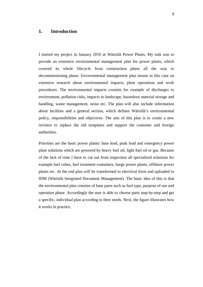
1. Introduction
I started my project in January 2010 at Wärtsilä Power Plants. My task was to
provide an extensive environmental management plan for power plants, which
covered its whole lifecycle from construction phase all the way to
decommissioning phase. Environmental management plan means in this case an
extensive research about environmental impacts, plant operations and work
procedures. The environmental impacts consists for example of discharges to
environment, pollution risks, impacts to landscape, hazardous material storage and
handling, waste management, noise etc. The plan will also include information
about facilities and a general section, which defines Wärtsilä’s environmental
policy, responsibilities and objectives. The aim of this plan is to create a new
revision to replace the old templates and support the customer and foreign
authorities.
Priorities are the basic power plants: base load, peak load and emergency power
plant solutions which are powered by heavy fuel oil, light fuel oil or gas. Because
of the lack of time I have to cut out from inspection all specialized solutions for
example fuel cubes, fuel treatment containers, barge power plants, offshore power
plants etc. At the end plan will be transformed to electrical form and uploaded to
IDM (Wärtsilä Integrated Document Management). The basic idea of this is that
the environmental plan consists of base parts such as fuel type, purpose of use and
operation phase. Accordingly the user is able to choose parts step-by-step and get
a specific, individual plan according to their needs. Next, the figure illustrates how
it works in practice.

10
Figure 1 Construction of EMP
1.1. Research methods
In the beginning we sketched with my supervisors’ the main viewpoints for the
project and decided what kind of power plants we want to emphasize in this work.
After when the task was defined I started to familiarize myself with the IDM,
which is the documentation system of company. I used during the research many
different technical handbooks from Wärtsilä database and utilized them in my
work. Another source of my work was World Bank Group’s Environmental,
Health and Safety guidelines (30th of April 2007), which is recognized worldwide
as minimum requirement for environmental plans. The Environmental, Health and
Safety Guidelines is a technical reference document with general and industry-
specific examples of Good International Industry Practice. The Guidelines contain
the performance levels and measures that are normally acceptable to International
Finance Corporation and are generally considered to be achievable in new
facilities at reasonable costs by existing technology. It contains information on
cross-cutting environmental, health, and safety issues potentially applicable to all
industry sectors. I also made several interviews with Wärtsilä engineers and site
managers. /10/
11
1.2. Structure of this thesis
This thesis consists of seven chapters. The first chapter consists of the general
information about thesis, purpose of the work and theory about environmental
management. The second chapter introduces Wärtsilä and Power Plants. The
chapters 3-6 consist of my research and comprise the Environmental Management
plan for power plant projects. I divided my work in the four parts: construction,
commissioning, operational and decommissioning phase. The construction
chapter defines Wärtsilä’s environmental policy and includes general information
about environmental systems, responsibilities and training. This part will also
specify the environmental impacts caused by construction works and some
general guidelines. The commissioning chapter introduces how the every section
of facility works and I tried to bring out some detailed information about the
process which helps to define environmental impacts. The operational- and
decommissioning chapters will give information about Wärtsilä Services
operations and gives some general guidelines how to act environmentally friendly
way after when Wärtsilä has left the site and handed plant over to the customer.
The last chapter presents conclusions and summary of thesis and some future
prospects how the EMP will be utilized in Wärtsilä.
1.3. Purpose of environmental plan
Kentucky Division of Compliance Assistance (DCA) defines environmental plan
as: “EMP describes the processes that an organization will follow to maximize its
compliance and minimize harm to the environment.” /12/ Provincial Government
of the Western Cape: Department of Environmental Affairs and Development
planning defines EMP as “An environmental management tool is used to ensure
that undue or reasonably avoidable adverse impacts of the construction, operation
and decommissioning of a project are prevented; and that the positive benefits of
the projects are enhanced.” /16/ In summary, its purpose is to reduce adverse
impact to sensitive environmental resources and to minimize disturbance for
neighborhood.

12
An EMP is sometimes even referred as pollution prevention plan because often
the main focus of plan is preventing certain pollutions. It might be also a useful
tool for companies to help address a variety of environmental issues such as
managing air emissions. EMP has also similar features with normal life cycle
analysis, because EMP should also include life cycle aspects for continual
improvements to assist best practice in environmental management. This project is
a good example of this kind of manner of plan. Health and safety issues are also
stated in EMP and these have to cover all prescribed legal requirements. It might
also serve own personnel on environmental issues such as guiding personnel in
organization towards certain objectives and increase safety issues. EMP should
also define exact roles and responsibilities for supervisors inside organization and
point out clearly required inspections and maintenance in practice. In the end
EMP should be reviewed occasionally to ensure it reflects the current situation. In
an ideal world EMP should continuously improve. The review of EMP should
include at least these things: any significant changes to activities or legislation,
result of inspection and maintenance programs and public complaints. Nowadays
environmental issues have gained a big role in business and importance of good
EMPs has grown vastly. Companies with good product and ecological footprint
will be succeeded, because customers require high quality products and services,
but they also expect environmental friendly products. /2/ /8/
1.4. Environmental management
Environmental management system is the company response to the growing
concern about the state of environmental impacts caused by company activities.
Environmental management systems can be seen as extension of the quality
management systems, which were developed in the 1980’s. The environmental
management system is the basis for the actions that the company takes to manage
its environmental effects. The environmental management system aims to
following goals:
- Minimizing environmental-, health and safety impacts and risks.
- Reduce pollutions and resource consumption.

13
- Develop more environmental efficient products in the future.
Environmental management includes an environmental policy of the company,
environmental assessments, environmental objectives, environmental programs
and environmental auditing. The environmental policy states company’s
commitment to improve its environmental performance and strategies. The
environmental assessments are divided to assessments for the company, product
and process. Environmental objectives express in which way the company is
intending to develop in the future. Environmental program means implementation
of environmental standards such as ISO 14001. /18/
The benefits of the environmental systems are first of all reducing the
environmental impacts and hazards but in the long run it will contribute
economical growth also. The environmental friendly image of the company will
improve the public image and raise asset value. It also ensures meeting the
tightening environmental requirements in the future.
1.4.1. Sustainable development
Sustainable development is defined usually according Brundtland Commission
(1987) “Enabling development that meets today’s needs without prejudicing the
ability of future generations to meet their own needs”/14/. As the world moves
through the twenty-first century, it faces an important challenge to protect and
preserve the earth’s resources to ensure healthy environment for the future
generations. Over the last several decades of environmental policy, the focus has
been to achieve environmental quality by reducing pollutions to a level that is
acceptable to society. In the late 1980’s policymakers realized that decision
making should be driven towards a much broader goal: sustainable development.
In 1992 in Earth Summit in Rio de Janeiro nations outlined guidelines how to act
in line with sustainable development, which contributes both: global
environmental protection and economic development in the long run. /14/
Regulations of economic activity have changed a lot of evolution of
environmental policies around the world, where command-and-control approach
14
has developed a new problem. The end-of-pipe regulations are not adequate
methods to control long-term implications of environmental damage and
furthermore this approach does not full-fill entire objective of sustainable
development. The comprehensive goal of sustainable development requires
changes in attitudes how society make market decisions. The challenge is to
achieve economic prosperity but change market activity so that natural resources
and environment are protected. /18/
The sustainable development is an ambitious goal. The broader goal of sustainable
development aims towards to industrial ecology concept, where entire life cycle of
the product, including all the materials and energy flows should be considered in
efforts to improve the environment. The primary purpose of industrial ecology is
to promote the use of recycled wastes from one industrial process as inputs in
another. It also supports optimal materials flows, which means efficient use of
materials and energy in production. On the other hand more familiar approach to
achieving sustainable development is pollution prevention. Pollution prevention
refers to initiatives that reduce or eliminates waste rather than deal with them at
the end of product cycle. Although the aims are different above, pollution
prevention and industrial ecology shares a common view that end-of-pipe policy
controls are not sufficient for achieving goals. In the end a quote from Albert
Einstein (1879-1955) condenses the whole message in a few words: “Intellectuals
solve problems, genuine prevent them.” /18/
1.4.2. Life cycle assessment
Industrial companies often calculate environmental impacts by using the life cycle
assessment (LCA). LCA is a process used to evaluate environmental load
associated with a product, process or activity. The process takes into account the
whole life cycle of the product, packages, processes and activities. It also includes
assessment of raw material production, manufacture and transporting. The process
begins by indentifying and quantifying energy and material usage and
environmental releases. The collected data is used to assess the impact of material
usage, energy consumption, and releases to environment. Furthermore the data
will be evaluated and modifications for the process can be implemented to achieve
15
environmental improvements. The benefit of this method is that environmental
improvements can be seen in seen in each step in the LCA process, which exposes
the hot spots from the process. For example the raw materials alone may be used
to identify opportunities for reducing emissions, energy and material use. In
summary LCA provides help to decision making to incorporate consideration of
energy and material use, transportation and disposal. LCA represents a detailed
framework of the products and benefits of the changes in the process can be easily
calculated, evaluated and combined with existing pollution control and prevention
approaches. /15/
1.4.3. ISO 14000 standards
The International Organization for Standardization (ISO) was established in 1947.
During its 50-year history ISO has published more than 3000 technical and non-
technical standards in all fields. The history of ISO 14000 began in 1990 with
creation of an organization of 50 business leaders with an interest in environment
and development issues. The ISO 14000 is a standard for environmental
management systems that is applicable to any business, regardless of size, location
or income. The aim of the standard is to minimize harmful environmental impacts
caused by business activities, for example decreasing the pollution and wastes to
achieve continual improvement of environmental performance. It is important to
underline that ISO 14000 standards are environmental management not
performance standards. That is why it focuses on the core element of an
environmental management without defining specific performance targets. The
ISO 14000 series also covers standards on environmental auditing, audit
procedures, auditor criteria, audit management, initial environmental reviews,
environmental site assessment, environmental labelling, performance evaluation
and life cycle assessment. /3/ /17/
1.4.3.1. ISO 14001 standard
ISO 14001 standard is probably the most well-known environmental management
system standard. The important distinction between ISO 14001 and ISO 14000 is
that ISO 14001 is the specification, describing the core elements for certification

16
or self-declaration of an environmental management system, while ISO 14000 is a
non certifiable guidance standard. The specification of ISO 14001 shares common
management system principles with the ISO 9000 series of quality standards and
the company might use an existing management system as a basis for
environmental management systems. The ISO 14001 standard defines
requirements for an environmental management system how to develop and
implement a policy and objectives, which takes into account legal and other
requirements and environmental impacts. According the scope of ISO 14001, the
standard is applicable to company who wishes to accomplish:
- Implement, maintain and improve an environmental management system
- Assure itself of conformance with its own environmental policy
- Demonstrate conformance to others
- Seek certification by an external organization
- Make a self determination and declaration of conformance with ISO 14001
The company has liberty to choose if they want to implement ISO 14001
throughout the entire organization, or only for specific units or activities. /17/

17
2. Wärtsilä
2.1. General information
Wärtsilä is a Finnish manufacturer of large diesel and gas engines for use in
powering ships and electricity generation. The company offers also operation and
maintenance services for the ship power and power plants. Wärtsilä has operations
in 160 locations in 70 countries and 19,000 employees around the world.
Headquarter is located in Helsinki, furthermore there are operations in Vaasa,
Turku, Raisio and Espoo. Mission and vision of Wärtsilä is to provide lifecycle
power solutions to enhance customers business, whilst creating better
technologies that benefit both the customer and the environment. Wärtsilä aims to
be the most valued business partner of its customer’s /20/
Figure 2 Areas of business in Wärtsilä /20/
2.2. Power plant types
Wärtsilä Power Plants is a leading supplier of power plants for decentralized
power generation. The solutions cover power plants for steady base load
operation. Balancing peak loads, emergency operations and covering the needs of
own energy production for example in cement, petroleum- and gas industry.

18
The assets in power plant market are strong and wide product range, a high
efficiency rate and fuel flexibility deliveries, all-inclusive turnkey packages, full
operations support and a distinctive product offering.
2.2.1. Heavy- and light fuel power plants
Wärtsilä oil power plants are suitable for stationary and floating base-load plants,
stand-by applications for decentralized power production and for emergency
plants. Oil power plants are powered by heavy-, light- crude fuel oil or bio fuels.
The product range comprises oil- and multi-fuelled power plants with outputs
ranging from 1 to 300 MW. Wärtsilä has delivered almost 4000 oil power plants
all over the world. Principal layout of oil power plant can be seen in figure 3
below. /28/
Figure 3 Oil Power Plant
19
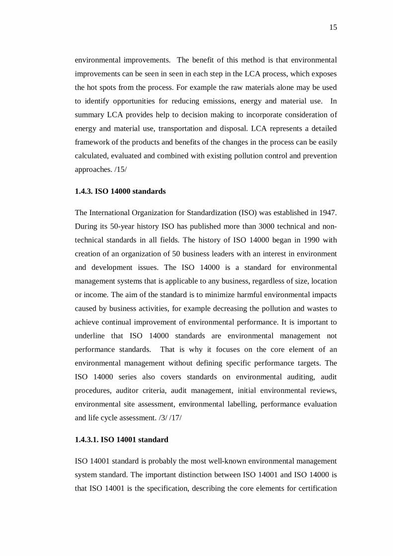
2.2.2. Gas Power plants
Wärtsilä gas power plants are designed for optimal performance in a wide variety
of decentralized power production applications such as stationary and floating
base-load plants, stand-by applications for decentralized power production and for
emergency plants. The gas engine plants are based on gas engine units. The
engines are designed for continuous operation on natural gas or in dual fuel mode
with gas and oil. They can run in island mode or parallel with the grid depending
on the operational demand. Wärtsilä has delivered close to 600 gas power plants
around the world. Principal layout of gas power plant can be seen in figure 4
below. /26/
Figure 4 Gas Power Plant

20
3. Construction Phase
From now on the chapters 3-6 consists of construction, commissioning,
operational and decommissioning phases, which comprises the Environmental
Management plan itself.
3.1. General
Wärtsilä has systematically worked for a long time to reduce the consumption of
energy and materials, lower various emissions and increase the recycling of waste.
The high efficiency, long life cycle and low emissions of Wärtsilä products helps
to reduce the consumption of natural resources and air pollution. Well-managed
environmental protection enhances business in all ways and allows society to
approve of and support Wärtsilä operations. The contribution of each and every
Wärtsilä employee is essential, as everything they do has an impact on both the
environment and the people around us.
Wärtsilä’s minimum requirement is compliance with the laws and regulations
related to environmental issues. It is Wärtsilä’s aim to cover the whole supply
chain and support our suppliers and customers in developing efficient procedures
for environmental management. Environmental performance is developed
according to the continuous improvement principles. The management of Wärtsilä
sets objectives and targets for environmental issues and regularly monitors how
these are achieved. The Environmental Management Plan complies with the
Wärtsilä’s policy and directives as well as ISO 14001 standard. /25/
3.1.1. Environmental policy
Wärtsilä considers environment protection to be one of its greatest responsibilities
and accordingly Wärtsilä undertakes to minimize the risk from hazards in all
aspects of its work and highlights the safe working procedures to protect the
property and natural environment. Power solutions of Wärtsilä are reliable, safe,
efficient and compliant with applicable legal requirements and regulations. The
21
end of official environmental declaration states that Wärtsilä’s skilled
organization acts as a responsible global citizen /22/
To achieve these aims of the Wärtsilä will:
1. Continually improve performance and reduce adverse environmental impact.
2. Provide where necessary adequate instructions, training and supervision of
work practices.
3. Ensure that necessary procedures to deal with emergencies and incidents are
known and that suitable and sufficient facilities are available at location.
4. Develop internal company standards for safe work procedures, health, and
environmental protection
5. Develop and maintain a safe work environment and system of work procedures
within the scope of legislative provisions, as far as is reasonably possible
Wärtsilä recognizes that achievement of an effective environmental management
program demands active and positive involvement of all levels of management,
and requires the full participation and support of all employees. Attitude is the key
factor and all employees are encouraged to develop a positive and continuing
concern for the environment by making environmental concerns a matter of
personal commitment. Each and every employee can make a significant
contribution. /25/
3.1.2. ISO standards
The environment and the sustainable development are important factors in the
business of Wärtsilä. Wärtsilä Finland has ISO 9001 certificate for quality
management systems, ISO 14001 certificate for environmental management and
OHSAS 18001 certificate for occupational health and safety management.

22
The List of Contents of Wärtsilä Finland Oy Environmental and Occupational
Health & Safety Manual is harmonized with standards ISO 14001 and OHSAS
18001.
According the ISO 14001-standard the focus of human resource development is to
improve Wärtsilä employee’s management skills, general skills and task- specific
skills. Each year the environmental and work safety team assesses the significance
of environmental and work safety aspects and risks in accordance with the risk
evaluation instructions. Based on this evaluation the significant environmental and
work safety aspects and risks are defined. After when the aspects and risks are
identified the team will prepare objectives and targets how to improve these issues
in the future and all actions will be documented and published. /39/
3.1.3. Training
Wärtsilä informs and educates personnel on environmental care and protection as
well as risk management within their areas of responsibility. Site person will be
given general environmental training. The training is carried out according to
Basic training instructions. Environmental training is given with the intention to
ensuring that each employee has general and specific environmental knowledge
and ability to act according to the EMP.
The contents of environmental training:
1. Basic education and training
2. Wärtsilä’s environmental policy
3. The main principles of the environmental system
4. Health and safety issues
5. Storage and handling chemicals
6. Waste and hazardous waste management
8. Instructions for emergency situations

23
9. Taking care of environment
Wärtsilä encourages its personnel to take full advantage by participating in other
orientations as well and also keeps record about given education. The new
workers will be given a compulsory orientation about management systems.
Visitor orientation:
In the beginning visitors shall be provided with required personal safety
equipments. The site visitors should be given a compulsory orientation about
health and safety, waste sorting and other general issues on the site. Visitors
should also sign an agreement, which states that they understand health and safety
regulations and are committed to obey these rules.
3.1.4. Responsibilities
Site organization at Wärtsilä construction site is responsible to ensure that the site
activities are performed in an environmentally responsible way. The following
figure illustrates the site hierarchy of Wärtsilä. In some big projects construction
manager might also be included in the site organization.
Figure 5 Site hierarchy of Wärtsilä

24
3.1.4.1.Construction manager
Construction manager observes and manages work on site. He is responsible for
following the safety policy and ensuring that every Wärtsilä’s employee on site
understand and comply with the policy and safety procedures. He communicates
with the Site manager, authorities, client, site personnel, subcontractors and other
project participants to make sure that the environmental incident prevention
instructions are followed.
3.1.4.2. Site manager
Site manager ensures that all employees, supervisors and subcontractors are
informed about environmental requirements, precautions and procedures. Site
manager should also implement the environmental protection and spill prevention
plan at site and make sure that oils, paints and chemicals, etc. are properly stored
transported, protected and handled to avoid spillages and safety risks to the site
personnel or property. He supervises that environmental incident prevention plan
is followed generally in all areas. He communicates with authorities, clients and
neighbors about the issues relating to construction site. In the end he assures that
demobilization activities have been properly taken care of by responsible persons
and all activities has been finalized according the site safety rules.
3.1.4.3. Commissioning Manager
Commissioning manager is the leader of the commissioning phase of power plant.
He ensures that all commissioning supervisors and subcontractors are informed of
environmental requirements, precautions, and procedures. He also assists in
implementing the environmental protection and spill prevention plan at site. He
supervises that all materials are properly stored, transported and protected to avoid
accidents and ensures that waste management plan is followed. After
commissioning phase he ensures that site has been cleared out properly before the
plant is handed over to the customer.

25
3.1.4.4. Section Manager
Section manager supervises his own area of operation and health and safety
issues. He also assists in implementing the environmental protection and spill
prevention plan at site. He supervises that oils, paints and chemicals, etc. are
properly stored transported, protected and handled to avoid any spillages or and
safety risks to the personnel or property.
3.1.4.5. Health and Safety Officer
Nominated safety supervisor will ensure that safety is carried out in daily
activities. Safety supervisor is responsible to ensure that all employees receive
adequate information, instructions and equipments according the safety
regulations of the project. Safety supervisor is responsible for the implementation
and co-ordination of the occupational health & safety manual and spill prevention
and control plan for the project. He maintains accident log recording all pertinent
accident information. He is also responsible for orientating of the safety rules and
regulations for new employees.
3.1.4.6. Section Supervisor
Specialized supervisor supervises his own area of operation and assists in
implementing the occupational health & safety manual, spill prevention and
control plan at site. He supervises also general issues such as waste management,
transportation, health and safety issues and general cleanliness of the site etc.
3.1.4.7. Workers
Subcontractors and their employees are committed to follow Wärtsilä’s safety
policy and are responsible for reporting accidents, injuries, hazards, failures of
tools and other issues of safety matters.
In summary all the site personnel are responsible for following the environmental,
health and safety instructions of Wärtsilä.

26
3.1.5. Reporting
All accidents, spills, near-miss and sickness situations shall be reported and
investigated properly. After the investigation, the preventive actions are
performed. According Wärtsiläs’s Occupational HSE handbook safety reports and
statistics will be collected once in a month as the 14001 standard requires. /27/
3.1.6. Precautions
Every power plant will have a specific emergency and evacuation plan in case of
natural catastrophes, which might occur in its area. For example if power plant is
located in area with high risk of earthquake or flood it will have a plan how to
operate and be evacuated in that situation. Plan should also include other possible
accident scenarios, such as fires, explosions, chemical spills etc. the primary
objectives are to save lives, avoid injuries and minimize damage to property
3.1.7. Risk analysis
Inspection of products has been evaluated and categorized according the ISO
14121-stadard and will be updated yearly. Risk analysis itself has been made
according the instructions of corporation.
Risk analysis is a tool for calculating probabilities of accidents at the site. The
risks have been evaluated with numbers from 0-5 depending how likely particular
risk is going to happen. So that number zero represents no risk and number 5
represents very high risk. According the calculations the most likely accidents to
happen at the site are: different kind of fires, for example ignition of oil or engine,
oil leakages from tank or engine, falling splashes outdoor tank or filling vessel,
different kind of crashes, for example truck or crane control error and high noise
levels caused by construction works. /32/
3.2. Environmental aspects
Usually a third party has drawn up for a power plant project an EIA
(Environmental Impact Analysis), which is a smaller-scale plan than EMP. It has
been made for identifying and assessing possible environmental impact associated

27
by the power plant. EIA is can be utilized when implementing a full-scale EMP.
Wärtsilä assumes that customer has taken all presumable environmental issues
into account in EIA already when choosing location of plant. That is why it is
justified that environmental permissions for power plant are in the first place on
customers responsibly.
3.2.1. General guidelines
In the beginning of construction works one general rule must be underlined to all
personnel: To keeping up general cleanliness all around the site. Personnel have to
maintain the tools, materials, equipments, vehicles and properties clean and in
order, and when tools are used them should be stored in order to safe location.
These principles concern all employees regardless one’s position in every phase
during the power plants lifecycle.
3.2.2. Transporting and traffic
During the construction period traffic and transports will increase substantially at
the site area, which increases air emissions, dust, noise and probabilities of
accidents. Hence speed limits and well organized traffic are required at the site
area. Special arrangements shall be done for refueling and maintenance vehicles.
They are allowed to drive along marked roads to specify unloading area only and
vehicle idling will be minimized preventing exhausting gas emissions. In order to
prevent oil spills all vehicles will be provided with the trip tray if they are found
to be leaking oil. In case of accident construction- and health and safety manager
will perform an extensive inspection, and make changes to prevent similar
accidents in the future.
3.2.3. Hazardous material storing
Hazardous materials and construction chemicals for example solvents, fuel,
cement additives and reactive chemicals will be stored in ventilated, separated,
isolated area and will be handled according to the material safety data sheets. All
the fittings, pipes and hoses etc. shall be also made from dedicated materials. All
refilled containers must be marked clearly, so that their identification will be easy.
28
All the hazardous material shall be stored indoor away from the direct sunlight
and heat. Storage area should be provided with proper spill sink to ensure that
spilled chemicals cannot reach regolith. Due to the reason that spilled hazardous
chemicals might cause contamination of land, health or fire risks. Spill kits should
be available in visible place on the site for cleaning up possible minor spills.
Regular inspection will be made by health and safety manager to prevent possible
accidents and maintain specific documentations of all hazardous materials at the
site.
3.2.4. Waste management
Global waste management plan aims to reduce generated waste and recycle.
Wärtsilä is committed to these regulations, which are united with its own
environmental policy. Waste management including sorting, hazardous waste,
transportation and disposal of waste will be done in accordance with existing rules
and regulations of local legislation. Wärtsilä practices good housekeeping and
operating practices, including inventory control to reduce the amount of waste
from materials that are out-of-date, off-specification, damaged or excess to plant
needs and try to recognize opportunities to return usable materials such as
containers.
The following waste will be generated during the construction:
- Waste associated with clearing the site, ground excavation and demolition
- General construction site waste: containers, wood, metal, etc.
- Dangerous waste: waste oils and polluted containers
- Ordinary waste: office and food waste etc.
Hazardous waste will be delivered to approved disposal site and shall store in a
manner that prevents contact between incompatible wastes and allows inspection
between containers for monitoring leaks or spills. Waste oil and chemicals will be
stored in isolated containers in a separate place. The storage area shall be provided

29
with proper fence and warning signs to prevent unauthorized accesses and
accidents.
3.2.5. Emissions to air
Exhaust gases from heavy trucks, oil tankers, and construction machinery will
pollute the atmosphere during construction phase. Also particular matter will be
produced due to construction and digging activities. This leads to fugitive dust
emissions and reduces air quality locally. Only way to reduce these emissions is to
avoid unnecessary traffic and idle running in the area.
3.2.6. Noise and vibration
Noise will be generated by plant and equipment associated with the construction
activities such as main civil works, piling vehicle movements etc. Construction
works will result in elevated noise levels on and close to the site. In some cases
noise levels might be very high caused by temporary noise peaks. Local residents
and authorities will be notified beforehand if it is considered necessary.
Based on British Standard 4142 survey of human response to noise, changes in
noise levels of 5 dB or less are unlikely to result in complains of nuisance, while
10 dB or more are likely to lead to complains. All vehicles and equipment should
be equipped with proper silencers and mufflers to reduce noise at the site. /5/
Construction works will also cause minor vibration to environment, which has not
significant impacts to neighborhood. According a British study that the nuisance
from ground vibration and building damage is unlikely to occur if the operation is
conducted at distances greater than 50 meters. Based on guideline for major
construction made by Victoria state of Australia says that Complains about air
vibrations from blasting have been received from people 100m away from the
activity. /6/ /9/
3.2.7. Impact to landscape
The facility construction works will have an adverse impact on the local landscape
character as a result of vehicle movements, construction activity and by the plant

30
itself. Wärtsilä will exercise care to the natural landscape and conduct
construction operations as to prevent any unnecessary destruction, scarring or
defacing of the natural surroundings in the vicinity of the work sites. This will
also include minimizing impact to flora and fauna. According to Wärtsilä
environmental policy all debris, spillages etc. should be removed and cleaned up
if possible. After completion of construction all temporary structures and roads
will be removed and rehabilitated as good as possible. Contractor should also
made disquisition about ground water issues to make sure that power plant will
not disturb hydrological cycle or contaminate ground water. Most of the cases
power plant does not have significant impacts to the quality and quantity of
ground water if the power plant is not situated in sensitive ground water area, and
if the contractor will dispose of its treated effluent within permissible limits of
regulations into wastewater carrying drain.
3.2.8. Contaminated land and erosion
Land is considered contaminated when it contains hazardous materials or oil
concentrations above background or naturally occurring levels. Construction
activities may pose the potential release of petroleum based products, such as
lubricants, hydraulic fluids, or fuels during their storage, transfer or use in
equipment. These are the main factors, which might cause contamination of land.
Trying to prevent these incidents Wärtsilä aims for using, impervious surfaces on
refueling areas and take extra care when transferring oil and hazardous fluids.
Before starting construction there has to be done a survey about the topography of
the area. The survey will identify critical areas for protection such as highly
erodible soils, steep slopes or bare areas and simulate presumable and maximum
rainfall. There is a risk that removed soil might cause faster erosion and can lead
to dust problem especially in desert locations. At the site sediment run-off should
be minimized by reducing storm water on the site. It will be done with efficient
storm water drainage system, which will be installed before any land disturbance
activities commence. Sediment mobilization and transports should also be
scheduled to avoid heavy rainfall periods. After construction of plant loose soil
will be removed or covered with vegetation to avoid particulate dispersion into
31
air. The excavated soil will be utilized for example in the leveling, grading and
pavement of the roads within the plant area.
3.2.9. Dust
Construction works can generate locally significant quantities of dust during
activities such as earthmoving operations on site, wind blow and traffic
movements. Wärtsilä aims to arrange adequate equipments for collecting or
preventing dust during the operations, for example roads will be provided with
adequate road drainage based on road with, surface material and maintain
artificial watering in sensitive areas.
3.2.10. Drainage system
Drainage system will be done accordance with local legislation. System will be
scaled up to be capable of dispersing maximum predicted rainfall, to ensure its
functionality in a storm. Sanitary wastewater might discharge in varying
quantities during construction. That is why adequate portable and permanent
sanitation facilities will be provided at the site. Contaminated water facilities will
be separated from rainfall drainage and if possible the sewage drainage will be
connected to municipal sewer system. Sludge will be collected and pumped to the
sludge tanks and will be treated either at the site or by some local company.
System will be designed to minimize continuous slopes where flowing water can
scour. To prevent scouring, drainage lines may need to be lined on velocity-
reducing structures, which reduces water velocity and prevents leakages of pipes.
One serious possible threat for environment is, if rain water and oil will be mixed
cause of leakage. That is why drainage system requires regular inspection all the
time.
32
3.2.11. Oil and chemical spills
Oil and chemical spills are one of the most likely accidents to happen in
construction phase. Spillages can come from construction equipment, motor
vehicles or temporary bulk oil storage areas. To prevent spillages adequate
equipments such as spill kits shall be kept on-site to deal with occurred spills. One
useful and relatively cheap method is to equip normal, empty shipping container
to an oil spill prevention container.
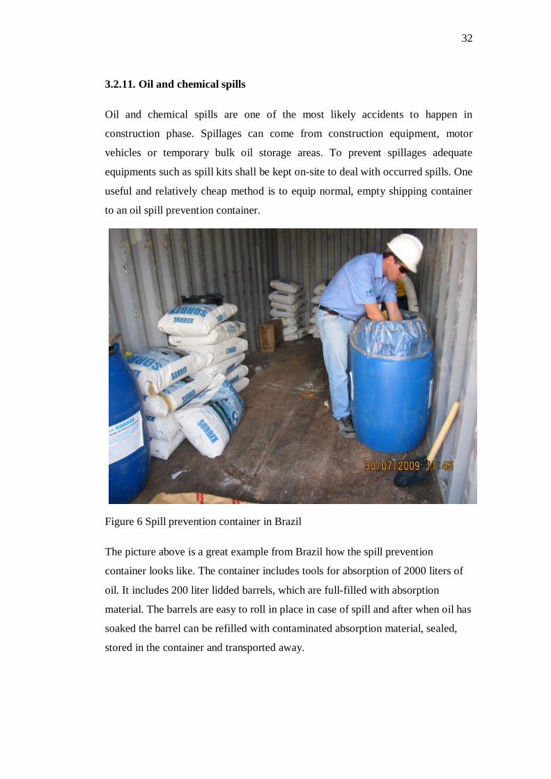
Figure 6 Spill prevention container in Brazil
The picture above is a great example from Brazil how the spill prevention
container looks like. The container includes tools for absorption of 2000 liters of
oil. It includes 200 liter lidded barrels, which are full-filled with absorption
material. The barrels are easy to roll in place in case of spill and after when oil has
soaked the barrel can be refilled with contaminated absorption material, sealed,
stored in the container and transported away.

33
3.2.12. Physical hazards
At construction phase there are lots of different kinds of physical hazards. For
example welding and hot works, working at heights, traffic and tools might cause
serious accidents. Wärtsilä is responsible for site’s health and safety and has
nominated officers to supervise these issues at the site. Health and safety issues
are also stated in the HSE handbook.
3.2.13. Maintenance and inspection
Ongoing surveillance is needed and required to ensure that the new risks are
identified as they rise. Aim of this plan is to be adjusted to ensure that any new
risks are adequately identified and managed.
3.2.14. Rehabilitation plan
Rehabilitation plan will be developed as soon as possible after design is finalized.
The site will be rehabilitated with above-mentioned methods so the impact on the
environment is minimal.
3.2.15. Instructions for exceptional situations
Exceptional situations refer to disturbances or accidents that may cause
exceptional emissions or effluents to the environment. Exceptional emissions or
effluents may be caused by damaged containers or pipes, problems in equipment
or machine operations, over-filling of containers, black-outs, neglected
maintenance or the human factor. Exceptional situations can also be planned, like
stopping and restarting of a process. Preventive measures must always be taken to
control exceptional situations. Preventive measures include, among others, the
following: identification of hazardous factors and situations, following prevention
procedures, training, orientation and information for employees and maintaining
of protection readiness
In case of accident or emergency situation plan of action is: Protect human life
and health in the first place. Secondly protect property and prevent environmental
damage. /24/

34
3.2.16. In case of spilling
All site personnel’s are responsible for taking all actions needed to prevent spills
at the site. In case of major spill it is mandatory to report as soon as possible after
discovery to the Construction Manager or Health and Safety Officer.
The following information has to be gathered as soon as possible after the spill
has been discovered and first reported: Seriousness of spill, estimation of the
quantity of released spill, location of the spill and proposed control methods and
actions. /36/
Procedures if spill incurs contamination of soil: Usually there are three general
approaches to cleaning up contaminated soil. At first Soil can be excavated from
the ground and be either treated or disposed, which is usually the best option in
case of oil spill. Soil can also be left in the ground and treated in place. This
procedure works usually when dealing with minor spills. Third option is to leave
the soil in the ground to prevent contamination from spreading, which is usually
done by placing a large plastic cover over the contaminated soil to prevent contact
with soil and rain water.
Treatment approaches can include: flushing contaminants out of the soil using
water, chemical solvents, destroying the contaminants by incineration or adding
material to the soil to encapsulate the contaminants and prevent them from
spreading.
The following general instructions shall be given to personnel if a spill occurs:
1. If possible try to stop outflow immediately. In case of fuel spill, the risk of fire
must be prevented if possible.
2. Inform the supervisor and other personnel and call assistance.
3. Remove vehicles and material from the risk zone
4. Arrange bund wall around the spillage with soil or sand to prevent liquid
spreading
35
5. Depending on consistency of liquid, spill can be covered with absorbent
material such as sawdust. Then let the oil/liquid be soaked and remove after few
hours. The method works for example with oil spills.
6. Contaminated materials and water shall be disposed with approved way and
ensure that further pollution is not caused during the cleaning works and
transportation.
After the cleaning of the spill it is necessary to restore and return all spill response
equipment. /7/
36
4. Commissioning Phase
4.1. General
The commissioning phase ensures that equipments are brought from mechanical
completion to a safe operational status. During and after commissioning phase the
number of personnel working at the site will be significantly reduced. Full site
commissioning works will involve the progressive testing of plant components,
units and system up to a full plant test run. Commissioning works involves
installation inspections and functional testing of each components, device and unit
to ensure safe operation, quality standards and contractual obligations. In
installation tests phase, civil, mechanical and electrical systems are checked and
started. In start-up phase each system performance is verified in predefined
sequence of tests. As the last phase of commissioning, each contractual
performance test is executed to demonstrate and prove to customer guaranteed
parameters. Depending on actual contract definitions of required performance, the
tests may include, for example: fuel consumption, electrical power output, heat
rate, lubrication oil consumption, and exhaust gas emissions levels etc.
Successfully tested and commissioned power plant will be handed over officially
to the customer. /23/
4.2. Environmental aspects
4.2.1. Emissions to air
Atmospheric emissions during commissioning period may be higher than normal
emissions due to the reason engines are driven with maximum capacity, however
these emissions will be temporary hence their impact will be minimal.
Atmospheric emissions comprise mainly carbon dioxide, oxides of nitrogen,
sulphur dioxide, carbon monoxide, particulate matters, and volatile organic
compounds.

37
4.2.2. Noise
Temporary noise peaks levels might be high during the commissioning phase.
One possible high level source of noise is pipe purging activities, where
compressed air is blew by high pressure through to pipe lines to remove
impurities from the system. Before the steam purging it is necessary to inform
neighborhood for disturbance and to ensure that all the persons in the vicinity of
the facility are provided with adequate hearing protection and given appropriate
warnings prior to event.
4.2.3. Oil Spills
Different kinds of oil spills might happen during the commissioning phase. The
common reasons for leaks is when starting the commissioning phase: valves are in
wrong position or loose, pipe connections are not tighten or malfunction in the
system, and due that reason spills to the environment might occur. Minor spills
can be easily avoided by following safety regulations. Procedures in case of oil
spills are the same as above.
4.2.4. Gas leaks
The gas power plant does not have any actual fuel tanks. The gas in conveyed
directly by pipes to the engine hall from the supplier. The only tanks in the area
are lubricating and service oil tanks, which are relatively small, compared to main
fuel tanks in oil power plant and thus the oil spills are rare. The gas powered
power plants are powered by natural gas, which consisting primarily of methane.
The gas itself is not toxic for human, but it could cause suffocation, head ache and
narcotic effects if inhaled big amounts. However the gas is easily flammable and
hence risks of explosion and fires are always present in case of leak. In the first
place all employees should be aware of basic conditions, which contribute ignition
of gas: adequate relation between air, amount of gas and an ignition source. Gas
leak can be detected by smell, noise and alarm from gas detector.

38
The following general instructions shall be given to personnel if a leak occurs:
1. If lives are not in danger try to shut down engine and gas supply. Closing the
gas supply main valve ensures that gas flow will stop.
2. Evacuate personnel and inform supervisors.
3. Try to ventilate the area as good as possible by opening doors, windows,
hatches etc. In case of fire, try to isolate area, which reduces the amount of
available oxygen.
- Avoid use of switches or electrical equipment to prevent sparks and other
sources of ignitions.
- Do not attempt to suffocate fire with water or extinguishers
After an accident or risk situation, safety supervisor shall write a report together
with plant managers to evaluate causes of the accident and make repairing actions
to prevent similar situation in the future.
4.3. Facility
4.3.1. Unloading station
The fuel unloading system contains pump units for unloading fuel from tankers or
fuel trucks to the storage tanks. When unloading fuel from the trucks or tankers
minor spills on the unloading area are common. Usually spills are caused by
leaking seals when connecting transfer hose to tanker or rupture on the delivery
hose. Drip cans should be placed under all connections to collect spills during
unloading and a safety barrier should be placed in front of the truck when
unloading fuel from the truck to prevent truck driving away while connections are
still in a place. Unloading area, especially HFO station must be roofed and
equipped with protecting ground layer to ensure that fuel cannot escape from area
to the environment. Used oily rags should be also removed immediately when
unloading is done and disposed according with waste disposal regulations. It is
very important when unloading fuel, there must be always at least one employee

39
in the vicinity of fueling area who is monitoring the pumping and is able to break
off pumping immediately if anything happens.
4.3.2. Tanks
Oil tanks are located in the vicinity of engine hall. The main purpose for the tanks
is to store and ensure the fuel reserve for the power plant. Tanks are usually built
according to the API 650 or EN 12285 standards and Fire protection has been
designed in compliance with NFPA 30. In some cases customer already has own
tanks, hence the customer is responsible that the tank area fulfils all required
safety regulations.
Heavy- and light fuel storage tanks will be located at approved plant yard. A
protection wall surrounds the area, which protects the rest of the area in case of oil
spill. The capacity of protection wall will be designed to be bigger than
volumetric capacity of the largest tank. The protection wall and oil tank area shall
be constructed with impermeable material to ensure that oil will not be able to
escape from the area. The valves and flange adaptors shall be oil resistant such as
nitrile butadiene rubber (NBR) when using rubber valves. The oil tanks have been
designed with sufficient buffering capacity into the tank for special situations.
Storage area will be enclosed by a security fence and be provided with proper
safety signs. These procedures will minimize substantially the risk of oil spills.
The quality of the fuel delivered has to be always in accordance with required
specification. The bad quality of HFO may lead to pump damage of filter
blockage, which might cause pump damages or oil spills. Impurities and water in
the fuel tank increases the risk of corrosion. That is why the tank must be drained
of water and settled impurities regularly. Another risk is too high fuel flow to the
tank during refilling, which causes overpressure and might even lead to tank
ruptures. Every project has unique specifications regarding these issues and as
long as the construction works and safety structures are done according the safety
regulations it is assumable that probability of accident is very small.

40
Venting fumes from the tank with source of ignition can cause the risk of flame;
to minimize this hazard the roof storage tank is equipped with ventilation hatch,
which releases the flammable vapors. Day and buffer tank has been equipped with
flame protectors, due to reason temperature of fuel, which has risen over its own
flash point. /33/ /37/
Figure 7 Tank area drainage system /37/
4.3.3. Water treatment
The purpose of water treatment system is to minimize the volume of water
contaminated with oil by keeping rain- and oily water unmixed. This is a problem
for drainage design, because the oily water from the bottom drainage of the fuel
oil tank have been able to enter to the area from where clean rain water are
collected. To keep pure rain water and oily drain water separate even in a storm
situation 0.5m height wall surrounds the tank drain pit. Minor amount of rain,
which drops directly to the tank drain pit, shall be led to oily water collection.
Principle layout can be seen above in Figure of tank area drainage system. When
installation of drainage system is completed, the first test drive is done by pure
water to ensure that system works properly and all valves are open.
The standard oily water treatment system for small plants consists only of oily
water collection and storage in a sludge tank. In this concept it is cheaper to
transport small amounts of oily water produced in the plant to appropriate disposal
site than to install treatment system. In bigger plants an oily water treatment unit
41
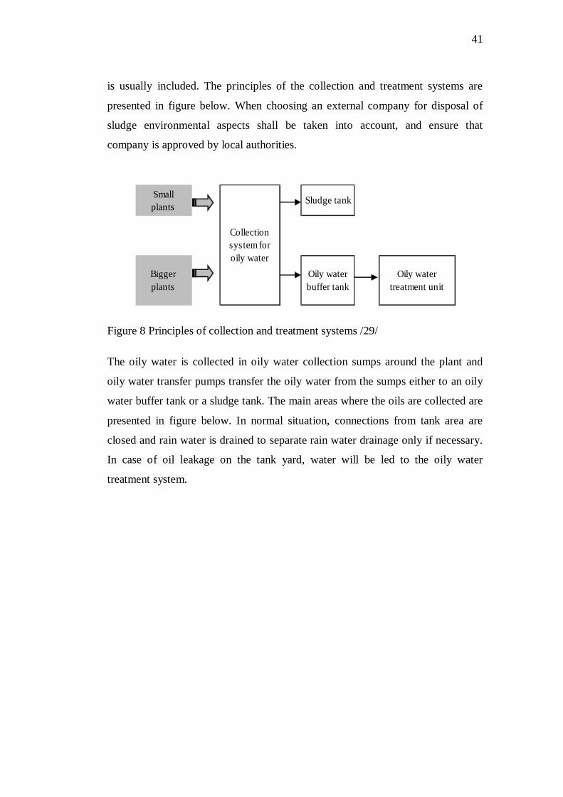
is usually included. The principles of the collection and treatment systems are
presented in figure below. When choosing an external company for disposal of
sludge environmental aspects shall be taken into account, and ensure that
company is approved by local authorities.
Figure 8 Principles of collection and treatment systems /29/
The oily water is collected in oily water collection sumps around the plant and
oily water transfer pumps transfer the oily water from the sumps either to an oily
water buffer tank or a sludge tank. The main areas where the oils are collected are
presented in figure below. In normal situation, connections from tank area are
closed and rain water is drained to separate rain water drainage only if necessary.
In case of oil leakage on the tank yard, water will be led to the oily water
treatment system.
Smallplants
Sludge tank
Biggerplants
Oily waterbuffer tank
Oily water treatment unit
Collectionsystem foroily water

42
4.3.3.1. Oily water collection with treatment unit
Figure 9 Diagram of oily water collection and treatment unit /29/
The oily water treatment is usually done by Senitec Oily Water Treatment Unit,
which is based on dissolved air flotation enhanced by chemical treatment, and
activated carbon filtration. Main contaminants of untreated wastewater are oil,
grease, suspended solids and metals.
The quality of treated water fulfills the World Bank requirements and can be
disposed to sewer. In the system there are three main chemicals, which are used in
the process:
- Coagulant: Aluminium chloride AlCl3 (pH < 2)
Aluminium is classified as hazardous according to the EU directives. It
irritates eyes, skin and may cause also irritation to the respiratory system.
If ingested seek medical attention immediately. In case of spill methods
for cleaning up are: Soak up with inert absorbent material and sweep up,
shovel into suitable containers for disposal and neutralize pH-value.
Spilled chemical will cause acidification of environment and waters
and due that reason flushing chemical into surface water, sewer or ground
water system is strictly forbidden. /31/

43
- Flocculant: Adipic-acid C6H10O4
Adipic-acid is not classified as hazardous. It may cause some slight skin,
eye and respiratory irritation. If ingested seek medical attention
immediately. In case of spill methods for cleaning up are: Sweep up
and shovel into suitable containers for disposal. Small spills can be
washed away with plenty of water. The chemical does not cause long-
term adverse impacts to environment /30/
- Sodium hydroxide NaOH
Sodium hydroxide is classified as hazardous. It causes skin burns and
serious eye damage and if ingested seek medical attention immediately.
NaOH shall not be allowed to enter drains of water courses, because it
causes an increase of pH in the aquatic environment. In case of spill area
shall be covered with sand, soil or other suitable material and collect.
After collection wash residues with plenty of water. /1/
Figure 10 The process diagram /38/
44
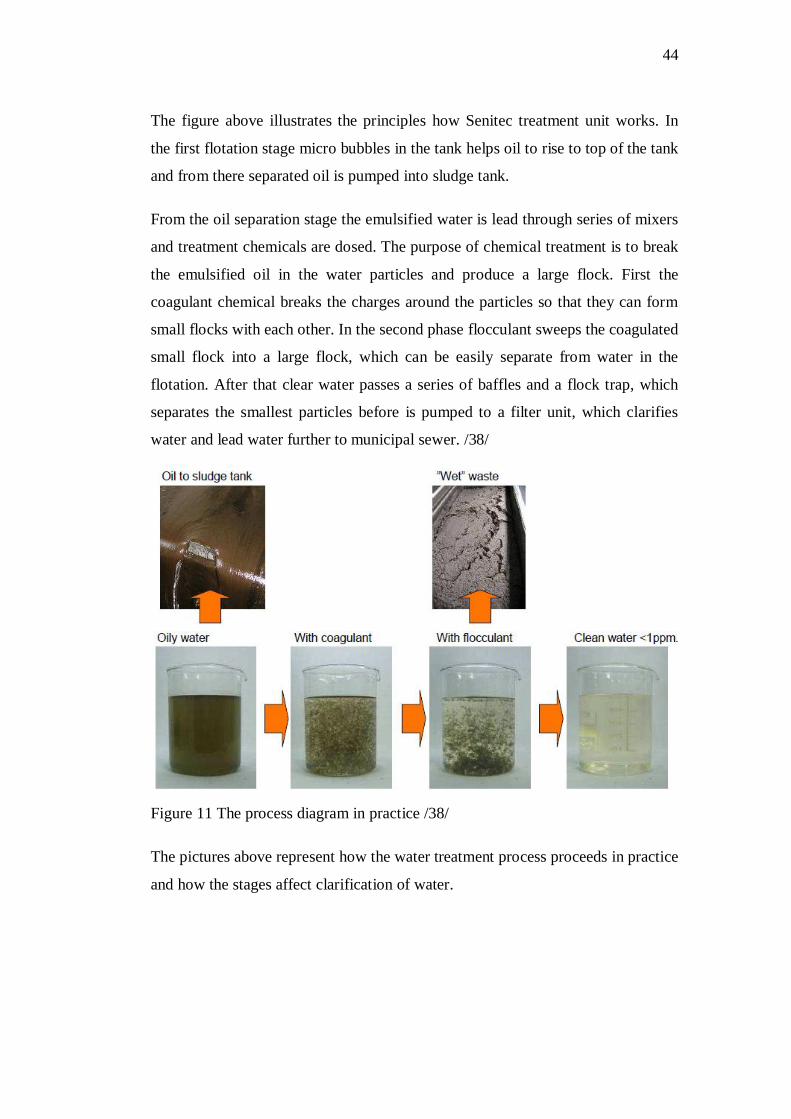
The figure above illustrates the principles how Senitec treatment unit works. In
the first flotation stage micro bubbles in the tank helps oil to rise to top of the tank
and from there separated oil is pumped into sludge tank.
From the oil separation stage the emulsified water is lead through series of mixers
and treatment chemicals are dosed. The purpose of chemical treatment is to break
the emulsified oil in the water particles and produce a large flock. First the
coagulant chemical breaks the charges around the particles so that they can form
small flocks with each other. In the second phase flocculant sweeps the coagulated
small flock into a large flock, which can be easily separate from water in the
flotation. After that clear water passes a series of baffles and a flock trap, which
separates the smallest particles before is pumped to a filter unit, which clarifies
water and lead water further to municipal sewer. /38/
Figure 11 The process diagram in practice /38/
The pictures above represent how the water treatment process proceeds in practice
and how the stages affect clarification of water.

45
4.3.3.2.Oily water collection without treatment unit
Figure 12 Diagram of oily water collection system /29/
The figure above represents water collection system without treatment unit. In this
system all generated waste liquids are stored in the sludge tank and transported to
treatment. The sludge tank is usually made of carbon steel and placed above the
ground. The tank is also equipped with instrumentation for monitoring the sludge
level and heating system. Environmental aspects are related to sludge tank for
example if an instrument failure causes overflow and due that reason sludge
escapes to the environment. However these accidents are very unlikely, if safety
instructions are followed.
Two important rules shall be underlined to the personnel:
-Normally closed valves shall be open only under supervision.
- Keep up general cleanliness especially in the tank yard to avoid drain
blockages
4.3.4. Separator
The separator unit maintains the quality of the fuel by removing water and solid
impurities. Malfunction in a separation unit may lead to overheating causing a

46
mechanical damage. Reason for malfunction might be for instance incorrectly
closed valves, fuel feed interruption or pump failure. Malfunction in the pressure
system might also damage separator. However probabilities of these accidents are
minimal. /33/
4.3.5. Lubricating oil system
Lubricating oil system is a vital part for an engine. Without a correct flow and
temperature of the lubricating oil engine will not work. The lubricant oil tanks
can also cause an overflow in case of malfunction of interceptors, which can lead
to oil spill to the environment. Procedures in case of spill are the same as
presented earlier.
4.3.6. Cooling system
The main purpose of cooling system is to remove generated heat from the engine
and keep the intake air receiver and lubricating oil temperature stable. Designed
cooling system is always project-specific. When planning the power plant cooling
system local ambient conditions and availability of water have to be taken into
account. Temperature as well as ambient humidity etc affects to the feasibility of
the different cooling methods.
Maintenance water tank is a vital part of the cooling water system, where the
cooling water from engine can be drained for the time of maintenance. Additive
chemicals for cooling water are also mixed in the tank. Main reason for mixing
additive chemicals with cooling water is to prevent corrosion and freezing in the
system. Used raw water must also fulfill following quality requirements:
pH min. 6.5
Hardness max 10 dH
Chlorides max. 80 mg/l
Sulphates max 150 mg/l

47
For locations where temperature goes below -0oC an anti-freeze chemical must be
added to the cooling water to prevent freezing. Usually this is done with ethylene
glycol C2H6O2, which is a toxic organic compound. Due to reason its harmful
impact to environment more environmental friendly alterative propylene glycol is
recommended to be used. Amount of anti-freeze chemical shall be minimized
especially when using ethylene glycol, because it cannot be drained in the storm
water pits or in the sludge system. The maximum allowed glycol content is 50
mass-percent of cooling water. Spills are unlikely happen, however if a spill
occurs outside of power hall or in the radiator area spilled liquids drains in the
storm water drainage but the assumable environmental impacts will be minimal if
liquid does not contain ethylene glycol. Maintenance water tank is another spot
where minor spills might occur especially during the refilling, however
environmental impacts in this case will be minimal also. If spill contains ethylene
glycol storm water valves shall be closed immediately. Procedures after spill shall
be to attempt collect spilled material with inert absorbent, for example with
sawdust or peat, and place in suitable, sealable containers. Contaminated area
must be flushed with large amounts of water and contact an approved waste hauler
for disposal of contaminated material. /13/ /21/
Figure 13 Diagram of typical cooling water system with radiator /21/

48
4.3.7. Pickling steel pipes
The commissioning process includes in installation testing phase also pickling and
flushing of pipes. Purpose of this is to remove impurities from the pipe system, for
example rust, slag, spatters and protect against corrosion. There are three different
pickling chemicals, which can be used in pickling works: citric acid, hydrochloric
acid and phosphoric acid. Wärtsilä recommends the use of citric acid as the first
choice in site conditions.
Safety rules must be underlined and followed: The pickling must be done outside
of the powerhouse, because of toxic fumes. If pickling is done with hydrochloric
or phosphoric acid then proper protection must be used: rubber gloves and boots,
protection glasses.etc. /19/
4.3.8. Flushing
Flushing will be done with flushing oil and the purpose of the flushing is to
remove all debris and foreign material from the pipelines, which could cause
damage to engines, or to auxiliary equipments. Flushing process must be done
under the supervision of commissioning manager and observe the system all the
time in case for possible oil leaks. /19/

49
5. Operational Phase
5.1. General
Wärtsilä offers different kind of agreements to the customers. In basic agreement
Wärtsilä leaves the site right after the plant has been commissioned and handed
over to the customer. In addition Wärtsilä Services offers different kind of
Operation and Maintenance agreements, which can cover partial or full time
maintenance support during the commercial operation phase. Wärtsilä service
agreement range cover: /34/
- Service agreements
Service agreements are designed to be tailored to customer’s exact needs,
letting customer choose from different levels of partnership, or a day-to-
day business relationship.
- Operation and Maintenance agreements
Operation and maintenance agreements typically mean that Wärtsilä
personnel take care of the operation of the power plant. Agreements
usually cover also overhauls at regular intervals, technical support during
major overhauls, maintenance reports and recommendations.
- Support agreements
Support agreements include extensive customized training and
development of site routines and assistance in planning different routines.
Agreement might also cover participation in site reporting and staff
management.
- Parts supply agreements
Parts supply agreements include supply of parts and materials to a
designated location with guarantee and information on upgrades.

50
- Reconditioning agreements
Reconditioning means restoring operational performance of older engines
and equipments. Usually the old parts are brought to the closest Wärtsilä
workshop where they will be dismantled and components replaced until
the engine has reached the required status. As a result the performance,
efficiency and reliability of the engine will probably raise and emissions
decrease because of product development and general improvements.
Reconditioning can also help to meet new environmental requirements,
reduce fuel and oil consumption and restore operational availability.
5.2. Environmental aspects
Wärtsilä encourages its customers to establish own environmental policy and
guidelines how to operate environmentally friendly way according the local
legislation. Operating according to the principles of sustainable development, will
also cut expenses in the long run and contribute life time of the power plant.
General cleanliness, which is the basis of good environmental way of action,
should emphasize to the personnel during the whole lifecycle of power plant.
5.2.1. Ambient air quality
Atmospheric emissions comprise mainly carbon dioxide, oxides of nitrogen,
sulphur dioxide, carbon monoxide, particulate matters and volatile organic
compounds. However when considering the entireness it is relevant to take into
account the local ambient air quality and how presumable air emissions will affect
on it, therefore the spot emissions from the stack only will not tell the absolute
truth of environmental impacts.
Wärtsilä will not take responsibly of air emissions, which are generated during the
operation phase. As mentioned before Wärtsilä assumes that customer has taken
all presumable environmental issues including air emissions into account already
when applying environmental licence to the plant.
The air emissions consist of:

51
- Sulphur Dioxide SO2
The sulphur dioxide is a toxic acid gas. SO2 and NOX are the main
factors of acid rain, which acids environment and harms
ecosystem. It has also direct effects to human health causing for
example respiratory illnesses. SO2 also causes formation of
microscopic aerosols, which according the latest knowledge
reduces the greenhouse effect.
- Oxides of Nitrogen NOX
Combusting produces oxides of nitrogen’s, of which NO2 is a
major product. NO2 is a toxic gas, even at relatively low
concentrations. Nitrogen oxides have harmful environmental
impacts, such as eutrophication of water systems, acid rains and
like SO2 it also forms microscopic aerosols in atmosphere, which
cools the climate. NOX compounds irritate also the lungs and
lower resistance to respiratory infection.
-Carbon Dioxide CO2
Carbon dioxide is a major greenhouse gas, which contributes the
climate change.
-Carbon Monoxide CO
Carbon monoxide is a colorless, odorless, tasteless and poisonous
gas produced primarily in incomplete burning. CO does not have
direct environmental effects but it is lethally toxic for human. Even
a short period of exposure can cause unconsciousness, which can
even lead to death.
-Particulate Matter PM10
52
Particulate matter is the general term used for a mixture of solid
particles. It includes aerosols, smoke, fumes, dust and ash.
Particulate matter has serious health effects. Long term contact has
been linked to several respiratory illnesses, for example asthma,
different kind of lung illnesses and even cancer.
- Volatile Organic Compounds
The volatile organic compounds are a common name for methane
and for other gaseous organic compounds. Non-methane VOC’s
forms in atmosphere troposphere ozone, which is greenhouse gas
as well along with methane.
5.2.2. Waste management
It is recommended that customer will establish own waste management plan,
which aims to prevent the amount of generated waste, encourages employees to
sort waste and emphasize importance of recycling. Plan should also include
regular monitoring program about consistency and amount of generated waste.
The record of solid and hazardous waste disposal form is attached in the end of
plan to the appendices, which can be utilized when implementing project specific
plan and record keeping.
Operational phase will typically generate:
Maintenance and industrial waste (wood, soiled rags, used filters, metal, plastic
etc.), office waste, containers and barrels (contaminated by oil or chemicals),
laboratory waste, used batteries, chemicals
Waste is recommended to be sorted and stored in special receptacles, which are
marked by different colors and written description to facilitate sorting. Usually
each color represents own waste class. Typically used colors are: red, brown, blue,
green, grey and white. Following sorting principles can be utilized as an example

53
guideline, because sorting must be done according the local legislation. Separate
receptacles should be provided for:
- Non-dangerous domestic waste (plastic, food scraps, boxes, small
articles, wrappings etc.)
- Hazardous waste (oily and greasy rags, used filters, batteries, chemicals,
contaminated containers etc.)
- Waste paper (clean paper, newspaper, magazines etc.)
- Waste metals
- Wood waste
- Used oil and chemical containers for contaminated liquids.
- Waste Glass
All generated waste should be handed over to the approved contractor, who is able
to safely recycle or decimate collected waste. Especially this goes for hazardous
waste, which can be very harmful for both environment and human health.
5.3. Precautions, health and safety
Wärtsilä highly recommends that customer obeys and continually maintain
established fire prevention and protection guidelines and other emergency plans.
Also health and safety handbook should be written and placed in visible place and
ensure that all workers are aware about written guidelines and committed to
follow them.
5.4. Traffic
In the operational phase traffic flow will probably decrease from construction
phase. However it is recommended to prepare traffic plan for the plant, which
includes for example: driving lines and directions, speed limits, routes for
refueling vehicles and safety issues.

54
5.5. Site security
Wärtsilä also highly recommends that site security issues will be ensured and
security plan for site be produced depending on the local circumstances and
legislation. It is recommend that plant should be surrounded by a security fence
designed to keep out all unauthorized persons and provided with security
lightning. Security guards should be on the duty 24 hours a day at the main gate
and depending on risk assessment more security posts might be considered. It is
recommended that the guards are also required to patrol around the plant
routinely. During the patrol the guard should be also responsible to report any
unusual events like spills, safety hazards, fires and vandalism etc. Also all
incoming vehicles should be registered at the gate when arriving and leaving. In
addition all suspicious packages, briefcases and bags should be opened for
inspection if necessary. It is recommended that personnel and visitors are required
to carry an identification card.

55
6. Decommissioning phase
6.1. General
After the operational phase when customer wants to run down facility the
decommissioning works will be done. Decommissioning is defined as the end of
the plant life or just a short-term shutdown. The aim of this phase is to minimize
impact to environment, contribute the sustainable development and generally
ensure safe dismantle of the used facility. The decommissioning works shall be
done in line with local regulatory requirements and according with BAT-
principles (best available technology) prevailing at the time. In practice this means
that whole site area including structures, engines equipments etc. are cleaned,
secured or demolished so that the plant will not pose a risk to public health or the
environment now or in the future. Power plant itself is a complex ensemble and
Wärtsilä advices its customers to contact Wärtsilä Services for assistance in
decommissioning activities.
6.2. Facilities
After when the plant has been shut down safely the dismantling works can be
executed. Basically this procedure means full scale closure and dismantling of
existing facilities. Wärtsilä encourages dismantling facilities in environmentally
friendly way by recycling materials, equipments and preventing and minimizing
contamination of surrounding environment. Before starting the dismantling works
some essential activities should be performed:
Make sure that fuel, oil and chemicals are unloaded and taken out from the
system. Pipes and should be flushed with pure water to remove hazardous liquids
from the system and exhume with care all underground pipes and tanks.
The facilities including structures, engine area, stacks etc. should be dismantled
according the health and safety regulations and consider the available re-using and
recycling possibilities. For example some materials might be re-used in other

56
sectors of economy such as in construction works, metal fabrication and energy
production etc. Before demolition it is important to check structures especially
engine hall in case of oil spills inside. If so, spillages should be cleaned before
demolition.
In addition Wärtsilä Services offers reconditioning agreements for engines, which
might be restored and re-sell and thus also benefit economically the owner. The
ditches should be re-filled with fresh soil after exhuming the pipes and
equipments to contribute natural rehabilitation. The operational and
decommissioning waste material should be treated, stored and transported with the
appropriate way. /4/
Dismantling of the facilities and demolishing of the constructions will generate
huge amount of waste. It will be also owner’s advantage to establish a waste
management plan for demolition waste. Systematical action will contribute
efficiency, recycling, health and safety, positive reputation of the company and in
the end cut waste disposal expenses.
Following types of waste is typically generated in demolition works. /11/
- Recyclable metallic waste
- Non-ferrous metals such as aluminium, copper, lead etc.
- Carbon and stainless steels from pipes, parts on equipments, doors,
steel wires, from radiators etc.
- Steel structures from buildings
- Building materials.
- Concrete waste
- Prefabricates and staircases, which might be suitable for re-use.
- Re-usable material for collection such as electric installation copper and
aluminum cables.

57
- Other waste
- Wood waste
- Glass waste and glass fibers from insulations
- Ceramic materials
- Plastic waste
- Other unsorted garbage from the demolition such as textiles, pasteboards,
non-recyclable cables, roof coverings etc.
- Hazardous materials
- Material contaminated by chemicals and oils
- Impregnated wood
- Batteries, fluorescents
- Asbestos material
- Liquid waste
- Oil, chemicals, cooling waters, sludge etc.
6.3. Environmental aspects
The biggest environmental threats during and after decommission phase are:
different oil and chemical spills, which may result contamination of land, erosion,
damage to natural landscape or biodiversity and contamination of ground water.
To prevent spills and other contaminations the same methods presented earlier can
be utilized. In some cases contaminated land in the area is referred as brown land,
which means that land has became contaminated already during the operational
phase. These so called brown lands should be treated or disposed also. When the
plant has been completely dismantled, the plant area should be restored as good as
possible by using the best available techniques prevailing at the time. The

58
rehabilitation works involves re-vegetation the area with fast growing species to
ensure fast natural landscaping and prevent soil from further damage through
erosion.
Figure 14 Dismantling power plant in Turkey, Sabodala Mining Company
6.4. Short-term shutdown
In some cases customer wants shutdown power plant for a temporary period of
time. When considering shutdown it is very important to know length of
shutdown and also take into account ambient conditions and make a specific plan
for every section of the power plant. These include shutdown, standby and
maintenance procedures during and after shutdown for generating set, auxiliaries
(fuel, lube oil, cooling, air, exhaust and water treatment systems), plant support
systems, electrical and control systems and civil issues. The significance of
investigation of actual ambient conditions (humidity, temperature, dust etc.) shall
be emphasized when choosing the methods for de-activating. Poorly prepared plan
may lead to serious damages to the engine and other equipments and thus cause
problems when re-activating the plant again. The shutdown requires also record
keeping and extensive documentation of all performed actions and logs. These
logs and documents provide vital information to re-activate safely the plant.
Wärtsilä highly recommends to contacting to Wärtsilä Services for assistance in
case of plant shutdown. /35/
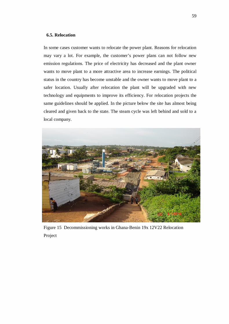
59
6.5. Relocation
In some cases customer wants to relocate the power plant. Reasons for relocation
may vary a lot. For example, the customer’s power plans can not follow new
emission regulations. The price of electricity has decreased and the plant owner
wants to move plant to a more attractive area to increase earnings. The political
status in the country has become unstable and the owner wants to move plant to a
safer location. Usually after relocation the plant will be upgraded with new
technology and equipments to improve its efficiency. For relocation projects the
same guidelines should be applied. In the picture below the site has almost being
cleared and given back to the state. The steam cycle was left behind and sold to a
local company.
Figure 15 Decommissioning works in Ghana-Benin 19x 12V22 Relocation
Project

60
7. Summary and Conclusions
The aim of the plan was to identify environmental aspects of different power plant
solutions and locations. During my research I found it very difficult to point out
differences between base load, peak load and emergency power plants. Due to
reason that this will document will be public it is important to point out, which
responsibilities are on Wärtsilä’s and customer’s responsibly. Especially this must
be emphasized when dealing with air and noise emissions. Wärtsilä will give, of
course typical emission rates but as a result of several interviews with Wärtsilä
engineers they convinced me that the spot emissions are not significant for our
environmental management plan, because usually the customer has taken these
issues into account already when applying the environmental license to power
plant. Wärtsilä can give only some general guidelines for operational and
decommissioning phase, because Wärtsilä cannot influence how customer runs
the plant after when it has officially handed away.
After all, in my opinion I succeeded well from the project and especially
construction and commissioning parts were successful. I think the structure and
content of my thesis is very logical, easy to follow and read. However one aim of
this project was to create a variable tool, where user can choose parts for the EMP
depending on plant type. In some point of research we realized with my
supervisors that this classification will be impossible, so we decided to
concentrate on general functions and environmental aspects of power plants.
I really enjoyed working with this project. The project taught me very much, I
literally went through all the basic operations of power plant and learned lots of
practical things, which I could never learn in the school. I think my weakness was
that I did not have earlier work experience in power plant sector and I had not
opportunity to visit real power plant and make observations by my own, so I had
to resort only to photos and interviews.

61
In the future my work in Wärtsilä will continue, and development of EMP will
continue as well. We had a thought to split my EMP into four pieces:
construction, commissioning, operation and decommissioning part, unite them
with new version of health and safety instructions. More information should be
gathered also and if possible to specify more differences between different plants.
In the end the final plan will be transformed to electrical form and programmed,
so that the user is able choose, which parts he wants in the EMP. The plan will be
also available for updates in the future and as stated in the introduction chapter the
EMP should continuously improve and follow the development.

62
LITERATURE
/1/ Akzo Nobel, Safety Data Sheet Sodium hybroxide [referenced 10.03.2010]. Available in Wärtsilä intranet.
/2/ Auckland Regional Council. A Guide to Developing an Environmental management Plan for ‘Industrial or Trade Activities’ in the Auckland Region August 2007 Version 7. [referenced 04.01.2010]. Available in www-form: <URL: http://www.arc.govt.nz/albany/fms/main/Documents/Environment/Pollution/EMP%20Guide.pdf>
/3/ Block, Marilyn R. 1997. Implementing ISO 14001. ASQC Quality Press Publication Catalog
/4/ British Energyplc, Fortum & TVO Oy etc, European Utility requirements for LWR Nuclear power plants 2003. Volume 2 Generic Nuclear Island Requirements, Chapter 16 Decommissioing, Revision D/03
/5/ British Standard 4142. Method for rating industrial noise affecting mixed residental and industrail areas. [referenced 25.01.2010]. Available in www-form: <URL: http://www.idox.cotswold.gov.uk/WAM14/doc/268029-Page6.pdf?extension=.pdf&page=6&id=268029&appid=0&contentType=application/pdf&location=VOLUME1>
/6/ D.J Transport and road research laboratory 1980. Ground vibrations from impact driving during road construction, Supplementary report p.544
/7/ Environmental Protection Agency. United States. Soil Contamination [referenced 27.01.2010]. Available in www-form: <URL: http://www.epa.gov/superfund/students/wastsite/soilspil.htm>
/8/ Environmental Protection Authority, Canberra, Australia 2009. Environmental Guidelines for Preparation of an Environmental Management Plan
/9/ Environment Protection Authority. Victoria, Australia 1996. Environmental Guidelines for Major Construction Sites. [referenced 21.01.2010]. Available in www-form: <URL: http://epanote2.epa.vic.gov.au/EPA/Publications.nsf/2f1c2625731746aa4a256ce90001cbb5/11a96b5fc29366764a2565fc0008e284/$FILE/480.pdf>
/10/ International Finance Corporation. World Bank Group. Environmental, Health and Safety General Guidelines 30th April 2007.
/11/ Jadrová vyrad’ovacia spolo nos , a.s Slovakia 2006, Environmental Impacts Assesment Report of V1 NPP Decommissioing [referenced 05.03.2010]. Available in www-form: <URL: http://www.ebrd.com/country/sector/nuclear/overview/funds/eianpp.pdf>

63
/12/ Kentucky Division of Compliance Assistance. Environmental Management Plans [referenced 29.12.2009]. Available in www-form: <URL: http://www.dca.ky.gov/kyexcel/Environmental+Management+Plans.htm>
/13/ Nalco Italia S.r.L. Certificate of analysis of ethylene glycol 2009 [referenced 17.02.2010]. Available in Wärtsilä intranet.
/14/ Nath, Bhaskar, Hens, Luc and Devust, Dimitri, 1996. Sustainable Development. VUB University Press
/15/ Pedersen Weidema, Bo 1993. Environmental Assement of Products. UETP-EEE, The Finnish Association of Graduate Engineers TEK.
/16/ Provincial Government of the Western Cape: Department of Environmental Affairs and Development Planning. Edition 1 June 2005. Guideline for Environmental Management Plans [referenced 29.12.2009]. Available in www-form: <URL: http://www.capegateway.gov.za/Text/2005/7/deadp_emp_guideline_june05_5.pdf>
/17/ Sayre, Don 1996. Inside ISO 14000: The Competitive Advantage of Environmental Management. St. Lucie Press
/18/ Thomas, Janet M. and Callan, Scott J. 2007. Environmental Economics: Applications, Policy and Theory. Bentley College
/19/ Wärtsilä. Cleaning and flushing of external piping [referenced 17.02.2010]. Available in Wärtsilä intranet.
/20/ Wärtsilä. Company overview [referenced 28.12.2009]. Available in www-form: <URL http://www.wartsila.com/,en,aboutus,0,generalcontent,57FDA3AE-A342-4D95-A732-D4C4D9B1A320,92D82833-AB87-4136-8EEB-57206C6F0DCF,,7000.htm>
/21/ Wärtsilä. Cooling water system [referenced 17.02.2010]. Available in Wärtsilä intranet.
/22/ Wärtsilä. Corporate Policy [referenced 05.01.2006]. Available in Wärtsilä intranet
/23/ Wärtsilä. Dome oilfield environmental impact assessment, The United Arab Emirates 2005.
/24/ Wärtsilä. EMS Working Instructions by Field Resources [referenced 26.01.2010]. Available in Wärtsilä intranet
/25/ Wärtsilä. Environmental policy [referenced 12.02.2010]. Available in Wärtsilä intranet

64
/26/ Wärtsilä. Gas Power Plants [referenced 01.03.2010]. Available in Wärtsilä intranet
/27/ Wärtsilä. Occupational Health & Safety and Environment guidelines for Construction and installation works [referenced 09.01.2006]. Available in Wärtsilä intranet
/28/ Wärtsilä. Oil Power Plants [referenced 01.03.2010]. Available in www-form: <URL: http://www.wartsila.com/,en,solutions,applicationdetail,application,2A68926D-351F-45E3-8DB0-EA231C542B75,C3A157E5-C923-42DB-87DB-64580D94BBDC,,4400.htm>
/29/ Wärtsilä. Oily water collection and treatment system [referenced 12.02.2010]. Available in Wärtsilä intranet.
/30/ Wärtsilä. Product Specification Adipic-acid [referenced 10.03.2010]. Available in Wärtsilä intranet.
/31/ Wärtsilä. Product Specification Aluminum chloride [referenced 10.03.2010]. Available in Wärtsilä intranet.
/32/ Wärtsilä. Risk analysis [referenced 21.01.2010]. Available in Wärtsilä intranet
/33/ Wärtsilä. Risk assessment report Ewekoro, Nigeria 2009 [referenced 02.02.2010]. Available in Wärtsilä intranet.
/34/ Wärtsilä. Service agreements [referenced 11.02.2010]. Available in www-form: <URL: http://www.wartsila.com/,en,productsservices,0,product,7969F5BA-FC3D-4C09-81CA-36EFF6874C21,334FFD40-EBC2-4AA7-BB83-106C47A7FAA6,,3100.htm>
/35/ Wärtsilä. Short Term Shutdown [Viitattu 02.03.2010]. Available in Wärtsilä intranet.
/36/ Wärtsilä. Spill Prevention and Control Plan [referenced 26.01.2010]. Available in Wärtsilä intranet.
/37/ Wärtsilä. Tank area drainage system [referenced 08.02.2010]. Available in Wärtsilä intranet.
/38/ Wärtsilä. The Process presentation [referenced 10.03.2010]. Available in Wärtsilä intranet
/39/ Wärtsilä. Ympäristö, työterveys- ja turvallisuuskäsikirja 26.03.2009 [referenced 01.03.2010]. Available in Wärtsilä intranet

65
APPENDICES
Appendix 1: Records of Solid Waste Disposal
Appendix 2: Det Norske Veritas, Management System Certificate
Appendix 3: Wärtsilä Policy for Quality, Health, Safety and Environment

66

67

68